1
•
•
•
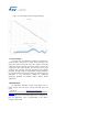
450mA, selectable) to make the system voltage rise
quickly up to a level that allows the system to wake up.
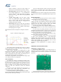
Fast-charge phase: When the battery voltage is above
the pre-charge threshold (VBAT > 3V), the STBCFG01
enters the fast-charge mode and increases the charging
current up to the IFAST value, which can be programmed
up to 1.25A.
Constant voltage phase: when the battery voltage
reaches the programmable floating voltage threshold
(VFLOAT, 3.60V to 4.70V in 20mV steps), the battery
voltage is kept constant and, as a consequence, the
charging current starts to decrease.
End of charge: during the CV phase when the charging
current reaches the termination current threshold (ITERM,
programmable from 50mA to 300mA in 25mA steps),
the charging process is stopped.
All the transitions between each phase are managed in a smooth
way.
Figure 2 - STBCFG01 charging cycle
The Over Voltage Protection (OVP) circuit protects the USB
port when the IC is providing power in boost mode. Output short
circuit protection and coil’s peak current protections are also
implemented.
In order to avoid excessive battery voltage drop in boost operation,
the OTG mode also features a programmable input average current
limit.
Battery Fuel Gauge
The voltage mode fuel gauge provides an accurate evaluation
of the Lithium-Ion battery’s state of charge.
At power-up, the fuel gauge algorithm uses the voltage
reading to provide a first evaluation of the SOC based on battery
modeling data. The evolution of voltage is then used to track the
changes of the SOC while cycling the battery. The external
software driver performs the temperature compensation.
The fuel gauge block can be adapted to different batteries.
Programmable parameters are used to tailor the algorithm to each
battery model.
In order to keep the optimal performance and avoid losing
information learned during battery cycling, the user is supposed to
save data contained in the device's volatile memory when power is
removed. The same data has to be restored at power-up.
The STBCFG01 also provides programmable alarms to notify
low battery voltage and low SOC conditions.
To enhance fuel-gauging accuracy with an error of 0.5% and
to reduce current consumption (25uA), a 14-bit Delta-Sigma
modulator using switched capacitors (SC) technique with fullydifferential input-output structure is implemented. The ADC also
reduces errors through state of art techniques such as nested
choppers and a digital moving average filter.
The device is fully programmable to be adapted to different
batteries.
STBCFG01's EVALUATION TOOLS
Other charger functions performed by the device are battery
detection and automatic recharge when battery voltage falls below
a threshold after the end of charge
Battery charger temperature and charging state are fully
monitored for fault conditions. In the event of battery over-voltage,
charger timers’ expiration, battery failure, and the condition of
battery voltage higher than input voltage, the charging process is
stopped and an interrupt signal can be generated.
The charger is stopped also in case of input under-voltage, input
over-voltage, and silicon over-temperature.
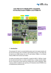
STBCFG01’s evaluation board
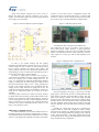
The STEVAL-ISB033V1 (Figure 3) provides full access to
STBCFG01’s functions and allows the user to quickly set-up an
evaluation bench to test the device performance in a real world
application.
Figure 3 - STEVAL-ISB033V1
OTG Architecture
The STBCFG01 features a bidirectional switching power
manager that can power an application and charge the battery using
the USB connector’s voltage as input source. Operating in reverse
mode, the same switching regulator can take power from the
battery to generate 5V on the USB connector and deliver up to
500mA for USB OTG applications without any additional
components.
The boost converter that implements the OTG function is a
peak current mode control with slope compensation. The
compensation network works at 2MHz or 3MHz.
A controlling technique of pulse width modulation (PWM)
mode and pulse frequency modulation (PFM) mode keeps the high
efficiency within width range of loading.
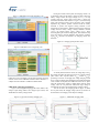
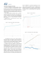
The board includes all passive components needed for proper
operation and provides several test points to monitor the device’s