1
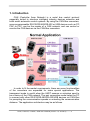
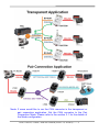
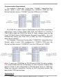
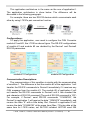
The UART to CAN Bus Converter (I-7530, I-7530T, I-7530-FT, I-7530A, I-7565, tM-7530) User’s Manual Warranty All products manufactured by ICP DAS are under warranty regarding defective materials for a period of one year from the date of delivery to the original purchaser. Warning ICP DAS assumes no liability for damages resulting from the use of this product. ICP DAS reserves the right to change this manual at any time without notice. The information furnished by ICP DAS is believed to be accurate and reliable. However, no responsibility is assumed by ICP DAS for its use, or for any infringements of patents or other rights of third parties resulting from its use. Copyright Copyright 2014 by ICP DAS. All rights are reserved. Trademark The names used for identification only may be registered trademarks of their respective companies. I-7530, I-7530-FT, I-7530A, I-7565 User’s Manual (Version 1.2, Jun/2014) -------- 1 Table of Contents 1. 2. 3. 4. Introduction .......................................................................................................... 3 1.1 Common Features of CAN Bus Converter ..................................... 6 1.1.1 Hardware .......................................................................................... 6 1.1.2 Software............................................................................................ 6 Specifications of the UART to CAN Bus Converters ......................................... 7 2.1 Specifications ................................................................................... 7 2.2 Pin Assignment................................................................................. 9 2.3 Block Diagram ................................................................................ 11 2.4 Wire Connection ............................................................................. 13 2.5 Terminator resistor ......................................................................... 15 2.5.1 Init/Normal DIP-Switch .................................................................... 17 2.5.2 LED Indication ................................................................................ 18 Software Utility ................................................................................................... 20 3.1 How to configure and test the CAN converters ........................... 21 Command list ..................................................................................................... 32 4.1 tIIILDD…[CHK]<CR> ....................................................................... 34 4.2 TIIIL[CHK]<CR> ............................................................................... 35 4.3 eIIIIIIIILDD…[CHK]<CR> ................................................................. 36 4.4 EIIIIIIIIL[CHK]<CR> ......................................................................... 37 4.5 S[CHK]<CR> .................................................................................... 38 4.6 C[CHK]<CR> ................................................................................... 40 4.7 P0BBDSPAE[CHK]<CR> ................................................................ 41 4.8 P1B [CHK]<CR> .............................................................................. 43 4.9 P2BBDSPAE[CHK]<CR> ................................................................ 44 4.10 P3SBCCCCCCCCMMMMMMMM [CHK]<CR> ............................... 46 4.11 RA[CHK]<CR> ................................................................................. 48 4.12 General Error code for all command............................................. 49 5. Troubleshooting ................................................................................................. 50 Appendix A: Cable selection .................................................................................... 51 Appendix B: Install I-7565 driver .............................................................................. 52 Appendix C: CAN Baud Rate Calculating................................................................ 58 Appendix D: Filter setting ......................................................................................... 63 Appendix E: Pair Connection ................................................................................... 64 I-7530, I-7530-FT, I-7530A, I-7565 User’s Manual (Version 1.2, Jun/2014) -------- 2 1. Introduction CAN (Controller Area Network) is a serial bus control protocol especially suited to structure intelligent industry devices networks and build smart automatic control systems. By using the CAN Bus converters, some programmable RS-232/RS-485/RS-422 or USB devices such as PC, PAC or PLC, can be the master of a CAN network, and can control or monitor the CAN devices via the CAN Bus converters. In order to fit the market requirements, there are some functionalities of the converters are expanded for some special applications. The transparent mode is useful when the UART sensors or actuators need to be a device of the CAN network. The pair connection mode helps the PC to connect with other RS-232/RS-485/RS-422/USB devices via CAN Bus for prompting the communication speeds or extending the communication distance. The application architecture may be as follows. I-7530, I-7530-FT, I-7530A, I-7565 User’s Manual (Version 1.2, Jun/2014) -------- 3 Node: If users would like to run the CAN converter in the transparent or pair connection application. Set the CAN converter to the Pair Connection Mode. Please refer to the section 3.1 for the details of the Mode configuration. I-7530, I-7530-FT, I-7530A, I-7565 User’s Manual (Version 1.2, Jun/2014) -------- 4 Here are the UART to CAN converters based on the different functionalities. I-7530: The RS-232 to CAN Bus converter with 9-pin D-sub connector. I-7530-FT: The Intelligent RS-232 to low speed fault tolerant CAN Bus converter. I-7530A: The Intelligent RS-232/485/422 to CAN Bus converter. I-7565: The USB (virtual COM port) to CAN Bus converter with 9-pin D-sub connector on the CAN side. tM-7530: The tiny-size RS-232 to CAN Bus converter with 3-pin spring type connector. Table: The Mail Difference between UART to CAN converters tM-7530 I-7530 I-7530A I-7565 I-7530-FT Interface RS-232 O O O X O RS-485 X X O X X RS-422 X X O X X USB X X X O X (Virtual COM) CAN Bus O O O O X (11898-2) CAN Bus X X X X O (11898-3) UART Baud Rate Max. (bps) 230400 115200 115200 921600 115200 CAN Baud Rate Max. (bps) 1000 k 1000 k 1000 k 1000 k 125 k Dimension Size Tiny Palm Palm Palm Palm I-7530, I-7530-FT, I-7530A, I-7565 User’s Manual (Version 1.2, Jun/2014) -------- 5 1.1 Common Features of CAN Bus Converter 1.1.1 Hardware NXP 82C250/TJA1042 CAN transceiver. Max. transmission distance over 1000 m based on CAN specification. Supports both CAN 2.0A and CAN 2.0B. Built-in a Dual-Watchdog function in the module. Provides RS-232/RS-422/RS-485/USB 2.0 communication interface. 1.1.2 Software Configuration by the software utility. Provides power, data flow and error LED indicator. Supports pair connection mode and transparent mode. Provides receive software buffer on CAN and UART side. Allows user-defined CAN baud rate. Supports user-defined end character on pair connection mode. Offers Listen Only Mode. Returns time stamp of the CAN messages. I-7530, I-7530-FT, I-7530A, I-7565 User’s Manual (Version 1.2, Jun/2014) -------- 6 2. Specifications of the UART to CAN Bus Converters 2.1 Specifications Item I-7530 I-7530T tM-7530 I-7530A I-7530A-MR I-7530-FT I-7565 CAN Interface Channel number 1 Spring type Connector 9-pin male D-Sub (CAN_L, CAN_H, N/A for others) connector Baud Rate (bps) 10 k ~ 1 Mbps DC-DC: 3000 VDC Isolation None photocoupler: 2500 Vrms DC-DC: 3000 VDC photocoupler: 2500 Vrms None Jumper-selected 120Ω terminator resistor Terminator Resistor 1 KΩ for CAN_H Jumper-selected and CAN_L 120Ω terminator resistor Specification ISO 11898-2 ISO 11898-3 ISO 11898-2 RS-232/USB Interface Connector 9-pin female D-Sub (TxD, RxD, RS-232 (TxD, RxD, GND), 9-pin female D- USB Type B GND, N/A for others) RS-485, RS-422 Sub (TxD, RxD, (Virtual COM) (Modbus slave functions GND, N/A for for the I-7530A-MR) others) 110 ~ 460800 110 ~ 115200 Baud Rate (bps) 110 ~ 230400 Data bit 5, 6, 7, 8 Stop bit 1, 2 Parity bit None, Odd, Even 110 ~ 115200 LED Round LED ON LED PWR LED ON LED ERR LED CAN LED ERR LED UART LED Power Protection Power reverse polarity protection, Over-voltage brown-out protection Power Consumption 1W Mechanism Installation DIN-Rail Dimensions 52mm x 86mm (W x L x H) x 32mm 1.5W 1W 72mm x 118mm x 33mm I-7530, I-7530-FT, I-7530A, I-7565 User’s Manual (Version 1.2, Jun/2014) -------- 7 110 ~ 921600 Environment Operating Temp. -25 ~ 75 ℃ Storage Temp. -30 ~ 80 ℃ Humidity 10 90% RH, non-condensing Note: 1. The CAN converters can’t handle the data reception and transmission of the RS-232 interface at the same time. That is to say that the full-duplex communication mode of RS-232 devices is not supported. 2. About more information of the I-7530A-MR, please refer to the web site as follows. http://www.icpdas.com/root/product/solutions/industrial_communication/fieldbus/can_bus/converter/i7530a-mr.html 3. Users need to Install the USB driver before using I-7565 for the first time. Please refer to Appendix B Install I-7565 Driver I-7530, I-7530-FT, I-7530A, I-7565 User’s Manual (Version 1.2, Jun/2014) -------- 8 2.2 Pin Assignment The UART connector for I-7530/I-7530FT/I-7530T/tM-7530: Table: RS-232 DB9 Female Connector (CN1) Terminal 3-wire RS-232 1 N/A 2 TXD 3 RXD 4 N/A 5 GND 6 N/A 7 N/A 8 N/A 9 N/A The UART connector for I-7530A: Table: RS-232/485/422 Connector (CN1) Terminal RS-232/485/422 1 (Y)DATA+ (RS-485) 2 (G)DATA- (RS-485) 3 N/A 4 Tx+ (RS-422) 5 Tx- (RS-422) 6 Rx+ (RS-422) 7 Rx- (RS-422) 8 N/A 9 RXD (RS-232) 10 TXD (RS-232) 11 (B)GND (RS-232) 12 N/A 13 +Vs (10 ~ 30 VDC Power) 14 (B)GND (Power) I-7530, I-7530-FT, I-7530A, I-7565 User’s Manual (Version 1.2, Jun/2014) -------- 9 (Y)DATA+ (G)DATA-- Tx+ TxRx+ Rx-- RXD TXD (B)GND -- +Vs (B)GND The CAN connector for I-7530/I-7530FT/I-7530T/I-7530A/I-7565: Table: CAN DB9 Male Connector (CN2) Terminal 2-wire or 3-wire CAN 1 N/A 2 CAN Low 3 CAN GND 4 N/A 5 CAN GND 6 N/A 7 CAN High 8 N/A 9 N/A The Power/CAN connector for tM-7530: Table: Power / CAN Connector (CN1/CN2) Terminal Power 1 +Vs (10 ~ 30 VDC Power) 2 GND (Power) 3 F.G. Terminal CAN 1 CAN_L 2 CAN_H 3 CAN_GND I-7530, I-7530-FT, I-7530A, I-7565 User’s Manual (Version 1.2, Jun/2014) -------- 10 2.3 Block Diagram The I-7530/I-7530T and tM-7530 provide CAN and RS-232 communication interfaces. The isolator is on the CAN side. The connector of the CAN port to the I-7530/I-7530T and tM-7530 are the D-Sub 9-pin male connector and the spring type connector respectively. Figure: The block diagram of the I-7530/I-7530T and tM-7530 The hardware profile of the I-7530-FT is the same as the I-7530/I7530T. The main difference between I-7530-FT and I-7530/I-7530T is followed CAN specification. The I-7530-FT is ISO 11898-3 device, which is also called low speed fault tolerance (LSFT) CAN device. There is no isolator on the I-7530-FT. Figure: The block diagram of the I-7530-FT The I-7530A provides four communication interfaces in one module. They are CAN, RS-232, RS-485 and RS-422 interfaces. Because the RS232, RS-485 and RS-422 are the same UART port, users can’t use them at the same time. The I-7530A also has isolator on the CAN side. Figure: The block diagram of the I-7530A I-7530, I-7530-FT, I-7530A, I-7565 User’s Manual (Version 1.2, Jun/2014) -------- 11 The I-7565 provides CAN and USB slave communication interfaces. On the USB interface, the I-7565 provides the virtual COM driver. Users can use the I-7565 instead of the I-7530 if the device only have USB host interface. The I-7565 is powered by the USB interface, it doesn’t need external power. The isolator of the I-7565 is on the CAN side. Figure: The block diagram of the I-7565 I-7530, I-7530-FT, I-7530A, I-7565 User’s Manual (Version 1.2, Jun/2014) -------- 12 2.4 Wire Connection The I-7530/I-7530T, I-7530-FT, and tM-7530 are RS-232 DCE devices, and uses the D-sub 9 pins female connector for the RS-232 interface. The following figure describes the wire connection between the PC and the modules. Figure: Connects the I-7530/I-7530T, I-7530-FT, or tM-7530 to the PC The I-7530A has one UART port with three kinds of interfaces. The following figure is the wire connection of the I-7530A to other UART device. When users use the RS-485 or RS-422 interface, it is strongly recommend to use twisted pair cable for the communication media. Figure: The UART wire connection to the I-7530A I-7530, I-7530-FT, I-7530A, I-7565 User’s Manual (Version 1.2, Jun/2014) -------- 13 The pin assignments of the CAN port (DB9 male) on the I-7530 series including I-7530, I-7530T, I-7530-FT, I-7530A, and I-7565 follows both the CANopen DS102 profile and the appendix C of the DeviceNet specifications. The wire connections are as follows. Figure: The CAN Bus wire connection to the I-7530 series The tM-7530 uses spring type connector on the CAN interface. The wire connection to the tM-7530 is below. Figure: The CAN Bus wire connection to the tM-7530 I-7530, I-7530-FT, I-7530A, I-7565 User’s Manual (Version 1.2, Jun/2014) -------- 14 2.5 Terminator resistor According to the ISO 11898 specifications, the ISO 11898-2 CAN Bus network must be terminated by two terminator resistors (120Ω) for proper operation, as shown in the below figure. If there are not only two terminator resistors or only have one terminator resistor on the CAN bus, the CAN network may be malfunction. About the terminator resistor of the I-7530-FT (follows the ISO 11898-3 specification), each I-7530-FT has its own terminator resistor. Users don’t need to take care about that. Figure: Terminator resistor for the ISO 11898-2 CAN network If users would like to enable or disable the terminator resistor inside the CAN converters, it is necessary to open the cover of the CAN converters and use jumper to do that. Here are the descriptions of how to enable or disable the terminator resistor of the CAN converters. Status JP3 position Enable (default) (Activate) Disable (Deactivate) Status JP4 position Enable (default) (Activate) Disable (Deactivate) I-7530, I-7530-FT, I-7530A, I-7565 User’s Manual (Version 1.2, Jun/2014) -------- 15 Status JP4 position Enable (default) (Activate) Disable (Deactivate) There is no terminator resistor in the tM-7530. Therefore, if users would like to use terminator resistor, it is necessary to wire a 120Ω resistance on the CAN bus, as following figure. I-7530, I-7530-FT, I-7530A, I-7565 User’s Manual (Version 1.2, Jun/2014) -------- 16 2.5.1 Init/Normal DIP-Switch The Init/Normal DIP-Switch is used to set the module run in the configuration mode or the operation mode. After users get the module, the configuration generally needs to be done first. Here is the description about the Configuration mode and the Operation mode. Configuration mode: This mode is used to set the UART or CAN communication parameters for baud rate, data format, filter, etc. After finishing the configuration, all of the parameters will be stored in the EEPROM of the CAN converters. Operation mode: This mode is used to convert the UART data and CAN messages with each other. Users can also use the UART commands to get module information or change some configuration of the UART or CAN parameters. Some of UART commands like “P2” and “P3” for changing the configuration in the normal mode will not be stored in the EEPROM. About the detail description, please refer to chapter 4 Command List. The DIP-switch position for different modules may be different. The DIP-switch of the I-7530/I-7530T, I-7530-FT, I-7530A, and I-7565 are on the back of the module, as following figure. The DIP-switch of the tM-7530 is in the bottom of the module. I-7530, I-7530-FT, I-7530A, I-7565 User’s Manual (Version 1.2, Jun/2014) -------- 17 Mode Position Normal Init 2.5.2 LED Indication Except the I-7530A-MR, all of the CAN converters provide 2 LED indicators. The ON LED is turned on when the module is running in Operation mode. If the module is in Configuration mode, the ON LED is flashed once per second. The ERR LED is used for indicating if the module is going wrong or not. If there is no error happened, the ERR LED is always turned off. If some error occurs, different CAN converters may have different behavior of the ERR LED. When the ERR LED is turned on or flashed, users can use the UART command string “S[CHK]<CR>” to get the details about the error. If the error is happened due to the overflow of the CAN or RS-232 software FIFO, users can use the UART command string “C[CHK]<CR>” to clear the error, or users may need to reboot the CAN converter for recovery. The position and behavior of the LED indicators to the I-7530/I-7530T, I-7530A, and I-7565 is as following figure. I-7530, I-7530-FT, I-7530A, I-7565 User’s Manual (Version 1.2, Jun/2014) -------- 18 LED Name ON LED ERR LED Condition Configuration Mode Operation Mode Some errors occurred LED Status Flashes once per second Turn on when no data needs to be send to CAN bus Flash once when sending a CAN message Always turned on The following figure shows the position and behavior of the LED indicators to the tM-7530. LED Name RUN LED ERR LED Condition Configuration Mode Operation Mode FIFO overflow CAN Bus Off CAN Error Passive Some errors occurred LED Status Flash once per second Turn on when no data needs to be send to CAN bus Flash once when sending a CAN or UART message Always turned on Flash Note: The tM-7530 provides 256 CAN frame FIFO, and 1000 CAN frame FIFO for other CAN converter. I-7530, I-7530-FT, I-7530A, I-7565 User’s Manual (Version 1.2, Jun/2014) -------- 19 3. Software Utility This section guide you how to configure the CAN converters and test them by using the VxCAN Utility. Users can free download the VxCAN Utility from the ICP DAS web site or get it from the ICP DAS fieldbus CD in the product package. Download & CD-ROM path: http://ftp.icpdas.com/pub/cd/fieldbus_cd/can/virtual_can/vxcan_utility/ CD:\fieldbus_cd\can\virtual_can\vxcan_utility\ The VxCAN Utility is based on the Virtual CAN technology which is developed by the ICP DAS and is used to integrate the CAN interfaces of the different CAN converters from the ICP DAS. All of the CAN interfaces found by the PC will be sequentially mapping to the virtual CAN ports by the Virtual CAN driver. Users just use the virtual CAN ports to develop their application, and don’t need to know what kind of CAN converter they use. It is very useful for transplanting the application to other platform with different CAN devices. Besides, the VxCAN Utility also provides the configuration interface for UART to CAN converters. Users can use this tool to configure the CAN converter, test the CAN devices, monitor the CAN network and analysis the CAN messages. For more information about the VxCAN Utility, please refer to the website or the VxCAN Utility’s manual : http://www.icpdas.com/root/product/solutions/industrial_communicatio n/fieldbus/can_bus/other/vxcan_driver.html Note: If users would like to use the old version utility tool of the CAN converter, please refer to the following path. http://ftp.icpdas.com/pub/cd/fieldbus_cd/can/converter/i7530/utility/old_version http://ftp.icpdas.com/pub/cd/fieldbus_cd/can/converter/i7530a/utility/old_version http://ftp.icpdas.com/pub/cd/fieldbus_cd/can/converter/i7565/utility/old_version I-7530, I-7530-FT, I-7530A, I-7565 User’s Manual (Version 1.2, Jun/2014) -------- 20 3.1 How to configure and test the CAN converters Configuration Interface: Step 1. Before powering on the CAN converters, users must set them to the Init mode. Users need to switch the Init/Normal DIPSwitch to Init position described in the section 2.5.1. Afterwards, power on the CAN converter and the Run LED indicator will be flashed once per second. Step 2. Connect the available COM port of the PC to the CAN converters, and execute the VxCAN Utility. Step 3. Click the button the PC. to search all CAN devices connected to Step 4. After finishing the search, the CAN converters (for example tM-7530 and I-7530) which are connecting to the PC or have connected to the PC will be list in the left side of the VxCAN Utility. If the tM-7530 is in Init mode, the VxCAN utility shows the “Init” information in the list. I-7530, I-7530-FT, I-7530A, I-7565 User’s Manual (Version 1.2, Jun/2014) -------- 21 Step 5. Click the tM-7530-Init in the list, the module configuration dialog is popped up. Different CAN converters may have the different information in the pop-up dialog. All of the settings in the module configuration dialog will be saved into the EEPROM of the module. The configuration is divided to three areas with different color. They are UART, Communication, and CAN configuration area. UART Configuration: * Baud rate: Set the UART baud rate. Different CAN converters have different max. UART baud rates. Users can select the proper UART baud for the CAN converters. * Data bit: Set the UART data bit. The CAN converters support 4 kinds of data bit configuration. * Stop bit: Set the UART stop bit. The CAN converters support 2 kinds of stop bit configuration. * Parity bit: Set the UART parity bit. The CAN converters support 3 kinds of parity bit configuration. I-7530, I-7530-FT, I-7530A, I-7565 User’s Manual (Version 1.2, Jun/2014) -------- 22 * Add Checksum: Set the CAN converters to enable or disable the checksum mechanism in the UART communication. If enable the checksum function, all UART strings from / to the tM-7530 must append two bytes of the checksum information. For checksum algorithm, please refer to the Node in the page 33. * Error Response: Set the CAN converters to enable or disable the error response mechanism in the UART communication. If enable the error response, the error code will be replied when users use the wrong UART command string to communicate with the CAN converters. * Timestamp Response: Set the CAN converters to enable or disable the timestamp response mechanism. If enable the timestamp response, the timestamp of each CAN message will be appended in the UART string when the CAN message are output from the UART interface of the CAN converter. This function may be invisible because it is not supported by the selected CAN converters. CAN Configuration: * CAN specification: Decide which CAN specification, CAN 2.0A (11-bits CAN ID) or CAN 2.0B (29-bits CAN ID), will be implemented. * CAN baud rate: Set the CAN baud rate. The CAN converters support several kinds of standard baud, such as 10K, 20K, 50K, 125K, 250K, 500K, 800K, 1000K, and 83.3K bps. If these baud rates don’t fit the users’ application, use user-defined CAN baud rate to configure the special CAN bauds. * User-defined CAN baud rate: If the user-defined CAN baud rate is used, users need to fill the value of the baud rate in the “Required Baud Rate” field and click the “Calculated” button to calculate the real value. If the real baud rate is not the same as the value in the “Required Baud Rate” filed, it means that the required baud rate can’t be reached because of the hardware limitation. The closest baud value will be implemented for instead. I-7530, I-7530-FT, I-7530A, I-7565 User’s Manual (Version 1.2, Jun/2014) -------- 23 If users want to get more information of the real baud rate, click the “Advanced” button. Users can select the proper parameters of the real baud rate for the applications. The field “Sample Point” means the percent of the sampling position of one bit data of the CAN message. The field “SJW” is the short for synchronization jump width. It is used to solve the problem of the phase shift between clock oscillators of different CAN devices. Generally, the sample point is set to close 87.5%, and the SJW is set to 1. * Set CAN ID Filter: Click the button to pop up the configuration dialog of the CAN ID filter. Users can use the acceptance code and acceptance mask to determine the accepted CAN messages by CAN message IDs. About how to calculate the Acceptance Code and the Acceptance Mask, please refer to the Appendix D. I-7530, I-7530-FT, I-7530A, I-7565 User’s Manual (Version 1.2, Jun/2014) -------- 24 Communication Configuration: It is used to set the communication mode of the CAN converters. In normal mode, the UART interface of the CAN converters only accept the command strings defined in the section 4. Any UART messages which don’t follow the command strings will be regard as wrong messages. When the CAN converters transfer the CAN messages to UART interface, the CAN messages are presented by the command strings. In pair connection mode, the CAN converters will transfer any UART message to the data field of the CAN messages whose message ID are fixed and predefined by the utility tool. It is useful for transparent applications or pair connection applications. The tM-7530 has an additional communication mode, “Listen Only” mode. In this mode, the tM-7530 can only receive the CAN messages and can’t send any CAN signal (include CAN Error Frame and the change of the ACK field) to the CAN network. Pair Connection Mode: When uses choose the Pair Connection in the Communication Mode, the pair connection configuration field will be presented. I-7530, I-7530-FT, I-7530A, I-7565 User’s Manual (Version 1.2, Jun/2014) -------- 25 * Fixed CAN ID: Set the fixed CAN ID for the transmitted UART data to the CAN network. Each CAN converter must have different configuration of the fixed CAN ID. If there are more than one CAN converter in the pair connection mode, the same fixed CAN ID will make the CAN ID conflict error while these CAN converter are transferring the UART data to the CAN message at the same time. * Response with CAN ID: Users can decide if the CAN ID needs to be transmitted with the UART data to the UART interface. In the pair connection application (see the picture of the section 1), the CAN ID always doesn’t need to be send to the UART interface. * End Characters of UART Commands: This function is used to set the end characters of the UART command received by the CAN converter. The UART data transferred from the CAN messages will not append the specific end characters. If the CAN converter gets the specific end characters from the UART interface, it is regarded as the end of the UART command, and the CAN converter will start to transfer the UART command to the CAN messages immediately. None: None end character is used. When the pair connection command timeout is reached or the UART buffer is full, the CAN converter will start to transfer the UART data to the CAN network. CR: Set the end character of the UART command to CR. The hexadecimal value of the ASCII code is ‘0x0D’. LF: Set the end character of the UART command to CR. The hexadecimal value of the ASCII code is ‘0x0A’. CR_LF: Set the end characters of the UART command to two characters, CR and LF. The hexadecimal value of the ASCII code is ‘0x0D’ and ‘0x0A’. LF_CR: Set the end characters of the UART command to two characters, LF and CR. The hexadecimal value of the ASCII code is ‘0x0A’ and ‘0x0D’. User-defined: This function allows users to define the special end characters, and is only supported by the tM7530. The UserDefined1 or UserDefined2 are used to configure one or two end characters. Take followings figure for example, select the item “User Defined2” and set the hexadecimal value of the end characters to be the 0x0D and 0x0A. When the CAN converter get the UART messages with end characters ‘0x0D’ and ‘0x0A’, it is regarded as the ending of the UART message. The CAN I-7530, I-7530-FT, I-7530A, I-7565 User’s Manual (Version 1.2, Jun/2014) -------- 26 converter will start to transfer the UART message to the CAN Bus. * Pair Connection Command Timeout: Only the tM-7530 and I-7530A-MR supports this function. The CAN timeout is used to decide the transformation timing of the CAN messages to the UART messages. After the CAN converter receives the CAN message, it will not transfer the CAN message to UART message until the time of the CAN timeout passes. If users would like to transfer the CAN message to UART messages immediately, set this value to 0. The function of the UART timeout is similar with the CAN timeout. It is decide the transformation timing of the UART messages to CAN messages. Only the configuration of the end characters of the UART message is none, the UART timeout is useful. After receiving one character from the UART interface, the CAN converter will not transfer the data until the time of the UART timeout passes. About details of the pair connection, please refer to the Appendix E for reference. Save and default value button: After finishing the configuration, users can click the button “Save All Setting” to save the configuration in to the EEPROM of the CAN converter. If users would like to recover the parameters to the factory default, click “Load Default Setting” button to recover all of the configuration parameters to be default value. Afterwards, I-7530, I-7530-FT, I-7530A, I-7565 User’s Manual (Version 1.2, Jun/2014) -------- 27 users can use the button “Save All Settings” to save the default parameters in to the EEPROM of the CAN converter. The default values of the parameters of the CAN converter are shown below. RS-232: RS-232 Baud rate = 115200/921600(for I-7565) Data Bit =8 Stop Bit =1 Parity = None Add Checksum = No Error Response = No TimeStamp Response = No CAN: CAN Specification = 2.0A CAN bus Baud rate = 125K Acceptance Code = 000 Acceptance Mask = 000 Communication: Mode: Normal I-7530, I-7530-FT, I-7530A, I-7565 User’s Manual (Version 1.2, Jun/2014) -------- 28 Test Interface: Step 1. Set the Init/Normal DIP switch of the CAN converter to normal mode, see the section 2.5.1. When the CAN module runs on the normal mode, the run LED indicator will be turned on. If the CAN converter sends or receives the CAN messages, the run LED will flash once per message. Step 2. Connect the COM port of PC to the CAN converter, and execute the VxCAN Utility. Step 3. Click the search button connected to the PC. to search all CAN converters Step 4. Afterwards, the searched CAN modules are listed in the left window of the VxCAN Utility I-7530, I-7530-FT, I-7530A, I-7565 User’s Manual (Version 1.2, Jun/2014) -------- 29 Step 5. Click the CAN port of the CAN converter to set the CAN parameters of the CAN converter. Check the “Active Port” and Click “Confirm” button to enable the CAN port of the CAN converter. The parameters set here are not stored in the EEPROM. If users would like to configure the other parameters expect the CAN parameters, please use Configuration interface of the VxCAN Utility to do that. Step 6. Click “Start” button to open test interface. Send Area Received Area The test interface is divided to two areas. One is for sending CAN messages, and the other is for reception. If users want to send CAN I-7530, I-7530-FT, I-7530A, I-7565 User’s Manual (Version 1.2, Jun/2014) -------- 30 message, fill the data into the corresponding field, and click “Send” button. If the CAN converter gets any CAN messages, they will be shown in received area automatically. About the details for the VxCAN Utility operation please refer to the users’ manual of the VxCAN Utility in the following web site. http://ftp.icpdas.com/pub/cd/fieldbus_cd/can/virtual_can/vxcan_utility/ I-7530, I-7530-FT, I-7530A, I-7565 User’s Manual (Version 1.2, Jun/2014) -------- 31 4.Command list For easy application, we provide 11 command strings to allow users to send and received commands and responses through the CAN Converter, like I-7530. It can cover most applications of different requests. The general formats of the commands for the CAN Converter modules are in ASCII data format and given below: Command Format: <Command>[CHK]<CR> <Command> : The RS-232/RS-485/RS-422/USB commands of the CAN Converter. [CHK] : 2-character checksum value. It is effective only if the checksum mechanism is set to enable. For checksum algorithm, please refer to the Node in the page 33. <CR> : All RS-232/RS-485/RS-422/USB commands of the CAN Converter must end with the character “<CR>” (The ASCII value is 13). The 11 command formats are given in the following table. More detailed information related to of the each command will be described in the following sub sections. Table: Command list table Command Description tIIILDD…[CHK]<CR> Send or receive a standard data frame. TIIIL[CHK]<CR> Send or receive a standard remote frame. eIIIIIIIILDD…[CHK]<CR> Send or receive an extended data frame. EIIIIIIIIL[CHK]<CR> Send or receive an extended remote frame. S[CHK]<CR> Read the status value of CAN Converter. C[CHK]<CR> Clear CAN Converter. FIFO error flag of overflow. I-7530, I-7530-FT, I-7530A, I-7565 User’s Manual (Version 1.2, Jun/2014) -------- 32 P0BBDSPAE[CHK]<CR> *Change the RS-232/RS-485/RS422/USB configuration and save it into EEPROM. P1B [CHK]<CR> *Change the CAN configuration and save it into EEPROM. P2BBDSPAE[CHK]<CR> Change the RS-232/RS-485/RS422/USB configuration and those parameter will not be saved.(only for firmware version 3.00 or more) P3SBCCCCCCCCMMMMMMMM Change the CAN configuration and [CHK]<CR> those parameters will not be saved. (only for firmware version 3.00 or more) RA[CHK]<CR> Reboot the CAN Converter module. * Note: This command will write parameters into EEPROM and the EEPROM is limited to 100,000 erase/write cycles. Checksum algorithm: The checksum [CHK] is 2-characters of the sum of the command message, from first character to the character before <CR>. When calculate checksum, the value of [CHK] is zero. For example: Command: Reboot the CAN Converter module, “RA[CHK]<CR>”. 1. Sum of the string = ‘R’ + ‘A’ = 52h + 41h = 93h. 2. Therefore the checksum is 93h and so [CHK]=”93”. 3. The command string with checksum =”RA93<CR>”. I-7530, I-7530-FT, I-7530A, I-7565 User’s Manual (Version 1.2, Jun/2014) -------- 33 4.1 tIIILDD…[CHK]<CR> Description: Send or receive a standard CAN data frame. Syntax: tIIILDD…[CHK]<CR> t III L DD… Represent a standard (2.0A) data frame. 11 bits Identifier (000~7FF) Data length (0~8) Input data frame value according to the data length (00~FF) Response: Valid command: No response Invalid command: ?<Error Code><CR> Note: It is necessary to enable the “Error Response” function in the CAN Converter Utility, in order to receive Syntax and/or communication error information at the host PC. Example: Command: t03F6112233445566<CR> Send a CAN message with a standard data frame. ID=03F, DLC=6, data1=11, data2=22, data3=33, data4=44, data5=55 and data6=66. I-7530, I-7530-FT, I-7530A, I-7565 User’s Manual (Version 1.2, Jun/2014) -------- 34 4.2 TIIIL[CHK]<CR> Description: Send or receive a standard CAN remote frame. Syntax: TIIIL[CHK]<CR> T III L Represents a standard (2.0A) remote frame. 11 bits Identifier (000~7FF) Data length (0~8) Response: Valid command: No response Invalid command: ?<Error Code><CR> Note: It is necessary to enable the “Error Response” function in the CAN Converter Utility, in order to receive Syntax and/or communication error information at the host PC. Example: Command: T2E88<CR> Send a CAN message with a standard remote frame. ID=2E8, DLC=8. I-7530, I-7530-FT, I-7530A, I-7565 User’s Manual (Version 1.2, Jun/2014) -------- 35 4.3 eIIIIIIIILDD…[CHK]<CR> Description: Send or receive an extended CAN data frame. Syntax: eIIIIIIIILDD…[CHK]<CR> e IIIIIIII L DD… Stands for the extended (2.0B) data frame. 29 bits Identifier (00000000~1FFFFFFF) Data length (0~8) Input data frame value according to the data length (00~FF) Response: Valid command: No response Invalid command: ?<Error Code><CR> Note: It is necessary to enable the “Error Response” function in the CAN Converter Utility, in order to receive Syntax and/or communication error information at the host PC. Example: Command: e1234567851122334455<CR> Send a CAN message with an extended data frame. ID=12345678, DLC=5, data1=11, data2=22, data3=33, data4=44 and data5=55. I-7530, I-7530-FT, I-7530A, I-7565 User’s Manual (Version 1.2, Jun/2014) -------- 36 4.4 EIIIIIIIIL[CHK]<CR> Description: Send or receive an extended CAN remote frame. Syntax: EIIIIIIIIL[CHK]<CR> E IIIIIIII L Stands for the extended (2.0B) CAN remote frame. 29 bits Identifier (00000000~1FFFFFFF) Data length (0~8) Response: Valid command: No response Invalid command: ?<Error Code><CR> Note: It is necessary to enable the “Error Response” function in the CAN Converter Utility, in order to receive Syntax and/or communication error information at the host PC. Example: Command: E010156786<CR> Send a CAN message with an extended remote frame. ID=01015678, DLC=6. I-7530, I-7530-FT, I-7530A, I-7565 User’s Manual (Version 1.2, Jun/2014) -------- 37 4.5 S[CHK]<CR> Description: Read the CAN Converter CAN Baud Rate and error flag message. Syntax: S[CHK]<CR> S Command character. Response: Valid Command: !CFFTTRRO[CHK]<CR> Invalid command: ?<Error Code>[CHK]<CR> ! Delimiter for valid command C current baud rate setting of CAN FF CAN register TT CAN transmit error counter RR CAN receive error counter O CAN or RS-232/RS-485/RS-422/USB FIFO Overflow flag Note: It is necessary to enable the “Error Response” function in the CAN Converter Utility, in order to receive Syntax and/or communication error information at the host PC. Furthermore, all response results are shown in the ASCII format. Users need to make an ASCII to hex format transformation in order to understand what the meaning is based on the following table. Table: CAN baud rate list AsciiToHex(C) Description 0 10K baud rate of CAN 1 20K baud rate of CAN 2 50K baud rate of CAN 3 100K baud rate of CAN 4 125K baud rate of CAN 5 250K baud rate of CAN 6 500K baud rate of CAN 7 800K baud rate of CAN 8 1000K baud rate of CAN 9 83.3K baud rate of CAN A User-defined baud rate of CAN I-7530, I-7530-FT, I-7530A, I-7565 User’s Manual (Version 1.2, Jun/2014) -------- 38 Table: CAN register list AsciiToHex(FF) Description Bit 7 Bus Off Mode Bit 6 Error Passive Mode Bit 5 Reserved Bit 4 I-7530 series: Overrun Buffer tM-7530: Reserved Bit 3 Stuff Error General Bit 2 CRC Error General Bit 1 Form Error General Bit 0 Acknowledgment Error General Table: CAN or RS-232/RS-485/RS-422/USB FIFO overflow flag list AsciiToHex(O) Description Bit 3 Reserved Bit 2 Reserved Bit 1 RS-232/RS-485/RS-422/USB FIFO Overflow Bit 0 CAN FIFO Overflow Example: Command: S<CR> Receive: !50000000<CR> Obtain some current information on the I-7530 module. The response will show the following results: CAN baud rate=250K, CAN register= normal, CAN transmit error counter=0, CAN receive error counter=0 and CAN/RS232 FIFO= normal. I-7530, I-7530-FT, I-7530A, I-7565 User’s Manual (Version 1.2, Jun/2014) -------- 39 4.6 C[CHK]<CR> Description: Clear the CAN Converter FIFO overflows error flag on the module. Syntax: C[CHK]<CR> C Command character. Response: Valid Command: No response. This will turn the ERR LED off after the ERR LED was turned on as a result of the CAN Converter FIFO overflow error flag. Invalid command: ?<Error Code>[CHK]<CR> Note: It is necessary to enable the “Error Response” function in the CAN Converter Utility, in order to receive Syntax and/or communication error information at the host PC. Example: Command: C<CR> I-7530, I-7530-FT, I-7530A, I-7565 User’s Manual (Version 1.2, Jun/2014) -------- 40 4.7 P0BBDSPAE[CHK]<CR> Description: Change the RS-232/RS-485/RS-422/USB configurations of the CAN Converter module. Module will be rebooted after saving these parameters into EPROM successfully. Syntax: P0BBDSPCE[CHK]<CR> P0 Command character BB RS-232/RS-485/RS-422/USB Baud rate D Data bit 0 = 5 bits Data formation 1 = 6 bits Data formation 2 = 7 bits Data formation 3 = 8 bits Data formation S Stop bit (0=1 stop bit, 1=2 stop bits) P Parity (0=None, 1=Odd, 2=Even) C Checksum (0=No, 1=Yes) E Error Response (0=No, 1=Yes); Table: RS-232/RS-485/RS-422/USB baud rate list BB Description 00 110 bps baud rate of RS-232 01 150 bps baud rate of RS-232 02 300 bps baud rate of RS-232 03 600 bps baud rate of RS-232 04 1200 bps baud rate of RS-232 05 2400 bps baud rate of RS-232 06 4800 bps baud rate of RS-232 07 9600 bps baud rate of RS-232 08 19200 bps baud rate of RS-232 09 38400 bps baud rate of RS-232 0A 57600 bps baud rate of RS-232 0B 115200 bps baud rate of RS-232 0C 230400 bps baud rate of RS-232, only for I-7565 and tM-7530 0D 460800 bps baud rate of RS-232, only for I-7565 0E 921600 bps baud rate of RS-232, only for I-7565 I-7530, I-7530-FT, I-7530A, I-7565 User’s Manual (Version 1.2, Jun/2014) -------- 41 Response: A valid command will let the module write the RS232/RS-485/RS-422/USB parameters into the EEPROM and then reboot the system. Invalid command: ?<Error Code><CR> Note: It is necessary to enable the “Error Response” function in the CAN Converter Utility, in order to receive Syntax and/or communication error information at the host PC. I-7565 supports only one 921600 baud rate on the firmware version 2.X or before. Example: Command: P00B30000<CR> Set the RS-232/RS-485/RS-422/USB baud rate=115.2K, data bit=8, stop bit=1, none parity, no checksum and No error responses into the CAN Converter module and then reboot the CAN Converter module. I-7530, I-7530-FT, I-7530A, I-7565 User’s Manual (Version 1.2, Jun/2014) -------- 42 4.8 P1B [CHK]<CR> Description: Change the CAN configuration of CAN Converter module. Module will be rebooted after saving these parameters into EEPROM successfully. Syntax: P1B[CHK]<CR> P1 B B 0 1 2 3 4 5 6 7 8 9 Command character CAN Baud rate Table: CAN baud rate list Description 10K baud rate of CAN 20K baud rate of CAN 50K baud rate of CAN 100K baud rate of CAN 125K baud rate of CAN 250K baud rate of CAN, I-7530-FT does not support 500K baud rate of CAN, I-7530-FT does not support 800K baud rate of CAN, I-7530-FT does not support 1000K baud rate of CAN, I-7530-FT does not support 83.3K baud rate of CAN, I-7530-FT does not support Response: A valid command will write the CAN configuration baud rate into the EEPROM and then reboot the module. Invalid command: ?<Error Code><CR> Note: It is necessary to enable the “Error Response” function in the CAN Converter Utility, in order to receive Syntax and/or communication error information at the host PC. This command does not support user-defined CAN baud rate function. Example: Command: P14<CR> Set the CAN baud rate=125K into the I-7530 module and then reboot the I-7530 module. I-7530, I-7530-FT, I-7530A, I-7565 User’s Manual (Version 1.2, Jun/2014) -------- 43 4.9 P2BBDSPAE[CHK]<CR> Description: Change and apply the RS-232/RS-485/RS-422/USB parameters. These parameters will not be saved. When the module is rebooted, the RS-232/RS-485/RS422/USB parameters will be recovered to the previous setting. Syntax: P2BBDSPCE[CHK]<CR> P2 BB D S P C E BB 00 01 02 03 04 05 06 07 08 09 0A 0B 0C Command character RS-232/RS-485/RS-422/USB Baud rate Data bit 0 = 5 bits Data formation 1 = 6 bits Data formation 2 = 7 bits Data formation 3 = 8 bits Data formation Stop bit (0=1 stop bit, 1=2 stop bits) Parity (0=None, 1=Odd, 2=Even) Checksum (0=No, 1=Yes) Error Response (0=No, 1=Yes); Table: RS-232/RS-485/RS-422/USB baud rate list Description 110 bps baud rate of RS-232 150 bps baud rate of RS-232 300 bps baud rate of RS-232 600 bps baud rate of RS-232 1200 bps baud rate of RS-232 2400 bps baud rate of RS-232 4800 bps baud rate of RS-232 9600 bps baud rate of RS-232 19200 bps baud rate of RS-232 38400 bps baud rate of RS-232 57600 bps baud rate of RS-232 115200 bps baud rate of RS-232 230400 bps baud rate of RS-232, only for I-7565 I-7530, I-7530-FT, I-7530A, I-7565 User’s Manual (Version 1.2, Jun/2014) -------- 44 0D 0E 460800 bps baud rate of RS-232, only for I-7565 921600 bps baud rate of RS-232, only for I-7565 Response: A valid command will let the module to apply the RS232/RS-485/RS- 422/USB configuration parameters. Invalid command: ?<Error Code><CR> Note: It is necessary to enable the “Error Response” function in the CAN Converter Utility, in order to receive Syntax and/or communication error information at the host PC. This function just supports firmware version 3.00 or more. Example: Command: P20B30000<CR> The module’s RS-232/RS-485/RS-422/USB configuration will be change to baud rate=115.2K, data bit=8, stop bit=1, none parity, no checksum and no error responses. When CAN Converter module was rebooted, the RS-232/RS-485/RS-422/USB parameter will be recovered to the previous setting. I-7530, I-7530-FT, I-7530A, I-7565 User’s Manual (Version 1.2, Jun/2014) -------- 45 4.10 P3SBCCCCCCCCMMMMMMMM [CHK]<CR> Description: Change the CAN configuration of CAN Converter module. This command will save the CAN configuration parameter into SRAM. When the module is rebooted, the CAN configuration will recover the previous setting. Syntax: P3SBCCCCCCCCMMMMMMMM[CHK]<CR> P3 S B CCCCCCCC MMMMMMM B 0 1 2 3 4 5 6 7 8 9 Command character CAN Specification 2.0A/2.0B CAN Baud rate CAN filter acceptance code CAN filter acceptance mask Table: CAN baud rate list Description 10K baud rate of CAN 20K baud rate of CAN 50K baud rate of CAN 100K baud rate of CAN 125K baud rate of CAN 250K baud rate of CAN, I-7530-FT does not support 500K baud rate of CAN, I-7530-FT does not support 800K baud rate of CAN, I-7530-FT does not support 1000K baud rate of CAN, I-7530-FT does not support 83.3K baud rate of CAN, I-7530-FT does not support Response: A valid command will let the module to apply the CAN configuration parameters. Invalid command: ?<Error Code><CR> Note: It is necessary to enable the “Error Response” function in the CAN Converter Utility, in order to receive Syntax and/or communication error information at the host PC. This command does not support user-defined CAN baud rate function. About CAN filter setting, please refer to section 3.2. I-7530, I-7530-FT, I-7530A, I-7565 User’s Manual (Version 1.2, Jun/2014) -------- 46 This function just supports above firmware version 3.00. Example: Command: P3040000000000000000<CR> Change the CAN baud rate=125K and acceptance code 0x00000000, acceptance mask 0x00000000 into the CAN Converter module. When CAN Converter module was rebooted, the CAN parameter will be recovered to the previous setting. I-7530, I-7530-FT, I-7530A, I-7565 User’s Manual (Version 1.2, Jun/2014) -------- 47 4.11 RA[CHK]<CR> Description: Reboot the CAN Converter module. If the module is displaying on but the CAN bus is off, users can use this command to reboot the module in order to allow it to work in order again. Syntax: RA[CHK]<CR> RA Command character Response: Valid command will reboot the CAN Converter module. Invalid command: ?<Error Code><CR> Note: It is necessary to enable the “Error Response” function in the CAN Converter Utility, in order to receive Syntax and/or communication error information at the host PC. Example: Command: RA<CR> The CAN Converter module will reboot after it had received this command. I-7530, I-7530-FT, I-7530A, I-7565 User’s Manual (Version 1.2, Jun/2014) -------- 48 4.12 General Error code for all command AsciiToHex (Error code) 1 2 3 4 5 Table: Error code table Description The head character of the command string is invalid. The length of the command string is invalid. The checksum of the command string is invalid. Reserved The RS-232/RS-485/RS-422/USB receiver is timeout. I-7530, I-7530-FT, I-7530A, I-7565 User’s Manual (Version 1.2, Jun/2014) -------- 49 5. Troubleshooting If the Error response function on the CAN Converter module is set to “Yes” (that means enable) via the CAN Converter Utility during the configuration period, the CAN Converter will send the error code to the RS-232/RS-485/RS-422/USB device of the host PC through the RS232/RS-485/RS-422/USB media when the CAN Converter produces an error message automatically during the operation mode. The meanings of these error codes are given below: Table: Error code table Error Description Possible causes & solutions code The RS-232/RS-485/RS-422/USB command string 1 Invalid header header is not “t”,”T”,”e”,”E”,”S”,”C”,”P0”, ”P1”, ”P2”, ”P3” nor “RA”. The data byte of the CAN Message does not match the data length of the CAN Message. For example: 2 Invalid length Error: t001512345<CR> Right: t00150102030405<CR> The checksum from the RS-232/RS-485/RS-422/USB command string does not matched with the checksum Invalid 3 calculated by the CAN Converter module. For example: checksum Error: t0012112209<CR> Right: t00121122FD<CR> The ASCII command strings are sent incomplete. For example: 5 Timeout Error: T0018 Right: T0018<CR> If the CAN Converter module’s CAN baud rate is not the same as the CAN baud rate on the CAN network, the ON LED on the CAN Converter module will be flash with a constant frequency because the CAN Converter module cannot send any CAN messages to the CAN network. Therefore, users will need to read the CAN Converter module status by using the command “S[CHK]<CR>”(in the section 4.5) to help users understand what is going in the module. In general, the following errors could occur: CAN media connection problem, terminal resistor problem, different baud rate configuration with CAN network and the like. I-7530, I-7530-FT, I-7530A, I-7565 User’s Manual (Version 1.2, Jun/2014) -------- 50 Appendix A: Cable selection The CAN bus is a Balanced (differential) 2-wire interface running over either a Shielded Twisted Pair (STP), Un-shielded Twisted Pair (UTP), or Ribbon cable. The CAN-L and CAN-H Wire start on one end of the total CAN network that a terminator of 120 Ohm is connected between CAN-L and CAN-H. The cable is connected from CAN node to CAN node, normally without or with short T connections. On the other end of the cable again a 120Ω(Ohm) terminator resistor is connected between the CAN lines. How to decide a cable type, cable length, and terminator depends on the baud rate in the CAN BUS network, please refer to the following table. Figure: Un-shielded Twisted Pair (UTP) Bus speed 50k bit/s at 1000m 100k bit/s at 500m 500k bit/s at 100m 1000k bit/s at 40m Table: Cable selection Cable Cable type resistance/m 0.75~0.8mm2 70 mOhm 18AWG 0.5~0.6 mm2 < 60 mOhm 20AWG 0.34~0.6mm2 22AWG, < 40 mOhm 20AWG 0.25~0.34mm2 23AWG, < 40 mOhm 22AWG Terminator Bus Length 150~300 600~1000m Ohm 150~300 300~600m Ohm 127 Ohm 40~300m 124 Ohm 0~40m Note: The AWG means a standard method used to measure wire. The numbering system works backwards from what people would think, the thicker (heavier) the wire, the lower the number. For example: a 24AWG wire is thicker/heavier than a 26AWG wire. I-7530, I-7530-FT, I-7530A, I-7565 User’s Manual (Version 1.2, Jun/2014) -------- 51 Appendix B: Install I-7565 driver This section will guide you on how to install the I-7565 converter under Windows XP, Windows 2000, Windows ME, and Windows 98 operating systems. (No support for WinNT). Download driver files from 1. Package CD:\CAN\Converter\i-7565\driver 2. http://ftp.icpdas.com/pub/cd/fieldbus_cd/can/converter/i-7565/driver/ The following steps will show how to install the device under Windows 2000. Basically, the procedures are also somewhat the same for other Windows operating systems. 1. Power on your computer and boot to Windows. 2. Locate the USB port of your computer and plug in the I-7565. 3. Windows will detect the new device and will initiate the Found New Hardware Wizard prompting you to install the software for the detected USB Device. Select to install from a list or specific location. Click Next to continue. 4. An “Install Hardware Device Drivers” window is shown. Click “Next” to initiate a search for a suitable driver for your device. I-7530, I-7530-FT, I-7530A, I-7565 User’s Manual (Version 1.2, Jun/2014) -------- 52 5. Select the “Specify a location” optional search locations. If the “CD-ROM drives” checkbox is selected, please insert the driver CD. Click “Next” to start the search. 6. If the “Specify a location” is selected, you much choose the correct path. Enter E:\CAN\Converter\I-7565\driver\win2k_xp(The ‘E’ is the Disk that Package CD put in). Click “OK” to start the search. I-7530, I-7530-FT, I-7530A, I-7565 User’s Manual (Version 1.2, Jun/2014) -------- 53 7. Once Windows finds the correct driver, click “Next” to install the driver. 8. Windows will then install the driver for the USB-to-Serial COM Port. Once installation is complete, Windows will notify you that it has finished installing the software. Click “Finish” to continue. I-7530, I-7530-FT, I-7530A, I-7565 User’s Manual (Version 1.2, Jun/2014) -------- 54 Note: When you finish the driver installation, please unplug the USB cable, and then plug the USB cable again. Verifying the Installation This section will show you on how to verify whether the I-7565 was properly installed. You will also need to determine the virtual COM port assignment made by Windows for the USB to CAN converter. Note: Before you connect the I-7565 for the first time, ensure that you do not attach any serial devices to the converter. You must only connect the I-7565 by itself. To verify whether the device is properly installed and determine the COM port assignment for the device: 1. Click “Start” “Settings” “Control Panel”, then double click on the “System” icon. Once the System Properties window is display, click on ” Hardware” tab and then click on the “Device Manager” button. Doubleclick on Ports (COM & LPT). If the device was correctly installed, you should now see the I-756X Converter device listing. This also means that Windows has assigned the device to the COM3 port. I-7530, I-7530-FT, I-7530A, I-7565 User’s Manual (Version 1.2, Jun/2014) -------- 55 2. If you need to reassign the virtual COM Port name to another Port number, you can double-click on the device (I-756X Converter) to view the properties. I-7530, I-7530-FT, I-7530A, I-7565 User’s Manual (Version 1.2, Jun/2014) -------- 56 3. Once you have verified that the device has been properly installed, you may now proceed to use the USB-to-CAN Converter to connect to CAN devices. Attach the CAN device to the CAN port of the adapter and then connect the USB connector to the USB port of your computer. Use the supplied driver for the serial device if needed. Uninstalling the Device Driver It is easy to uninstall the USB to Serial device driver: 1. Run the DRemover98_2K.exe Uninstall program which can be found on the Package CD, \CAN\Converter\I-7565\driver or at ftp://ftp.icpdas.com/pub/cd/can_cd/can/converter/i-7565/driver 2. The uninstall program will then prompt you whether you want to remove the utility program. Click “ OK “ to continue. 3. After the uninstall is complete, the program will prompt you to restart Windows. Click “Yes” to continue. 4. Windows will show a dialog box to notify you that the driver was removed successfully. Wait for Windows to restart your computer. I-7530, I-7530-FT, I-7530A, I-7565 User’s Manual (Version 1.2, Jun/2014) -------- 57 Appendix C: CAN Baud Rate Calculating This section will describe how to calculation CAN baud rate for I7530 series module, not including tM-7530, and using old version utility, CAN converter utility, to fill these parameters. The users can use user-defined CAN Baud rate by setting CAN Converter utility. There are four parameters for this function, please refer the below setting window. 1. Clock Mode: This parameter is means MCU clock. If the CAN Baud rate is less then 12k, this parameter value is “0”, others are “1”. 2. Bit Timing 1: This parameter is MCU’s bit timing register 1, please refer to the next page “Table: Bit Timing Register”. 3. Bit Timing 2: This parameter is MCU’s bit timing register 2, please refer to the next page “Table: Bit Timing Register”. 4. Bit Timing 3: This parameter is MCU’s bit timing register 3, please refer to the next page “Table: Bit Timing Register”. I-7530, I-7530-FT, I-7530A, I-7565 User’s Manual (Version 1.2, Jun/2014) -------- 58 How to fill those parameter: The Bit Timing register includes six kinds of parameter, BRP, SJW, PRS, PHS2, PHS1, and SMP. Please refer to the following table. Bit Bit 7 register Bit Timing 1 Bit Timing 2 Bit Timing 3 - Table: Bit Timing Register Bit 6 Bit 5 Bit 4 Bit 3 Bit 2 Bit 1 Bit 0 BRP5 BRP4 BRP3 BRP2 BRP1 BRP0 SJW1 SJW0 PRS2 PRS1 PRS0 PHS22 PHS21 PHS20 PHS12 PHS11 PHS10 SMP Figure: General structure of a bit period Generally, the register of SJW0, SWJ1 and SMP are always 0. One bit time consists of the time Tsyns, Tprs, Tphs1, and Tphs2, and can be divided into numbers of time slice (TQ) according to the system clock. The formula is shown below: Numbers of TQ = (System Clock) / (CAN Baud Rate) For example, when the CAN baud rate is 40 kbps, the numbers of TQ would be (20 MHz) / (40 Kbps) = 500. It means that the CAN converter can divided one bit time into 500 parts. The register PRS, PHS1, and PHS2 indicates the numbers of the time slice for Tprs, Tphs1, and Tphs2. I-7530, I-7530-FT, I-7530A, I-7565 User’s Manual (Version 1.2, Jun/2014) -------- 59 The formulas are shown below. Tprs = (PRS+1) * TQ Tphs1 = (PHS1+1)* TQ Tphs2 = (PHS2 +1)* TQ Because the Tsyns is defined to 1 TQ, therefore one bit time can be presented as below. Tbit = 1 TQ + (PRS+1) * TQ + (PHS1+1)* TQ +(PHS2 +1)* TQ And the sample point is defined below: Sample point = (Tsyns + Tprs + Tphs1) / (Tsyns + Tprs + Tphs1 + Tphs2) = (3 + PRS + PHS) / (4+PRS+PHS1+PHS2) Because the maximum value limitation of the register PRS, PHS1, and PHS2, the numbers of the Time Quantum always keeps in the range of 8 ~ 25. Therefore, users can use register BRP to scale it. For example, if set the BRP to 25 (the register value of the BRP is 24), the numbers of the Time Quantum is 500 / 25 = 20. Users can change the value of the PRS, PHS1, and PHS2 to adjust the required sample point. For example: If users want to set the CAN baud rate to “40K” by user-defined method and use the sample point 60%, set the clock mode to be 1 because the CAN Baud rate is more than 12K bps. When the Clock mode is 1, the MCU uses X2 mode and the system clock is 20MHz. Otherwise, the MCU uses X1 mode, and the system clock is 10MHz. The following steps will guide users to calculate the Bit Timing register step by step. 1. Calculate the numbers of the TQ: Numbers of the TQ = (System clock) / (CAN Baud Rate) = 20 M /40 k =500 I-7530, I-7530-FT, I-7530A, I-7565 User’s Manual (Version 1.2, Jun/2014) -------- 60 2. Adjust the numbers of the TQ by using the scale register, BRP. The TQ numbers always be in the range of 8 ~ 25. Here, numbers of the TQ of one bit time is scaled to 20, and the BRP would be as follows. 500 / 20 = 25 = (1+BRP) BRP = 24 3. Use sample point to decide the PRS, PHS1, and PHS2. Sample point = 60% = (3 + PRS + PHS1) / (4+PRS+PHS1+PHS2) Numbers of the TQ of one bit time = 20 = (4+PRS+PHS1+PHS2) “(3 + PRS + PHS1) = 12” can satisfy the sample point 60%. The PHS2 would be 7. If choose PRS = 2, then PHS1 =7. 4. Generally, the SJW and SMP are set to 0. The SMP is defined as below: => SMP = 0: once, at the sample point. => SMP = 1: three times, the threefold sampling of the bus is the sample point and twice over a distance of a 1/2 period of the Tscl. The result corresponds to the majority decision of the three values. According to the above calculation, the three Bit Time registers are as following: Bit Timing 1 register value is 0x30. Bit Timing 2 register value is 0x04. Bit Timing 3 register value is 0x7E. Then, the users can fill those parameter values as below: I-7530, I-7530-FT, I-7530A, I-7565 User’s Manual (Version 1.2, Jun/2014) -------- 61 Note: 1. After setting down, users must click “Calculate” button and calculate CAN Baud rate, otherwise CAN Converter utility could not save the parameter. 2. The function only supports on firmware version 3.00 or more, If the users do not know how to fill those parameter values, please feel free to contact us. I-7530, I-7530-FT, I-7530A, I-7565 User’s Manual (Version 1.2, Jun/2014) -------- 62 Appendix D: Filter setting The I-7530 series modules use acceptance code and acceptance mask for filter setting. The acceptance code and acceptance mask are used for filtering unnecessary CAN messages through RS-232/RS485/RS422/USB port. If users want to prevent the unnecessary CAN message through Re-conversions, they need to set the parameters of acceptance code and mask. Acceptance Code: The CAN ID bits that you want to get. Acceptance Mask: The CAN ID bits that you want to filter. In the acceptance code, the bit value ‘1’ means that you want to get this CAN ID bit. And in the acceptance mask, the bit value ‘1‘ means that you want to filter this CAN ID bit. For Examples: (1) If users want to get all the messages on the CAN bus, the setting must be as follow: In CAN 2.0A: Acceptance Code: Don’t care Acceptance Mask: 000 (2) If users want to get the message of CAN ID “123” (Hex) and filter all the other CAN message, the setting must be as follow: In CAN 2.0A: Acceptance Code: 123 (001 0010 0011 bit) Acceptance Mask: 7FF (111 1111 1111 bit) (3) If users want to get the message of CAN ID from “100” to “12F” (Hex) and filter all the other CAN message, the setting must be as follow: In CAN 2.0A: Acceptance Code: 10X (001 00XX XXXX bit) (X: don’t care) Acceptance Mask: 7C0 (111 1100 0000 bit) (4) The settings of CAN 2.0A and CAN 2.0B are the same. The different between CAN 2.0A and CAN 2.0B is the CAN ID bits. In CAN 2.0A: number of CAN ID bits is 11. In CAN 2.0B: number of CAN ID bits is 29. I-7530, I-7530-FT, I-7530A, I-7565 User’s Manual (Version 1.2, Jun/2014) -------- 63 Appendix E: Pair Connection The pair connection function usually needs two the same CAN Converter modules. For example, when these two I-7530s are in pair connection mode, all RS-232 commands transmitted from one of these two I-7530s will be put in the data field of CAN message. This CAN message will be transferred to RS-232 commands by another I-7530. The following section will show each condition for different pair connection configuration. Application 1: This application may be used in two general RS-232 devices which need to connect with each other, but the distance between is too large to communicate by using RS-232. Note: All of CAN Converter modules, like I-7530, I-7530-FT, I-7530A, I7565 have pair connection function. Using I-7565 with pair connection mode, it just supports RS-232 baud rate 115200 bps or less. Configurations: To apply this application, user need to configure the CAN Converter modules #1 and #2 as follows. The RS-232 configurations of CAN Converter modules #1 and #2 are decided by the Device1 and Device2 RS-232 parameters. module #1 Configuration module #2 Configuration I-7530, I-7530-FT, I-7530A, I-7565 User’s Manual (Version 1.2, Jun/2014) -------- 64 Communication Descriptions: For example, if there are 7 bytes data, “1234567”, transmitted from Device1 which is sent CAN messages by I-7530#1’s COM port, the Device2 will also receive “1234567” from the COM port of I-7530#2. The CAN ID in above figure is determined by the CAN specification selected by users. If users select CAN 2.0A, the CAN ID is 11-bit ID. If CAN 2.0B is used, the CAN ID is 29-bit ID. Here, assume users set the Fixed Tx CAN ID field of CAN Converter Device#1 to be 0x001 ( “0x” is for hexadecimal format) and CAN 2.0A is used, the CAN ID displayed in above figure is 0x001. For example, if there are 9 bytes data, “123456789”, transmitted from Device1 which is sent CAN messages by I-7530#1’s COM port, the Device2 will also receive “123456789” from the COM port of I-7530#2. Note: If users use 115200bps for RS-232 port of CAN Converter module, it is recommended that the configuration of CAN Converter module CAN baud is closed to the configuration of RS-232 baud, such as 125K bps. When you use pair connection function of CAN Converter module, the baud under 125K bps is proper. Application 2: I-7530, I-7530-FT, I-7530A, I-7565 User’s Manual (Version 1.2, Jun/2014) -------- 65 This application architecture is the same as the one of application1. The application architecture is show below. The difference will be discussed in the following paragraph. For example, there are two RS-232 devices which communicate each other by using I-7530’s pair connection function. Configurations: To apply this application, user need to configure the CAN Converter module #1 and #2, like I-7530 as above figure. The RS-232 configurations of module #1 and module #2 are decided by the Device1 and Device2 RS-232 parameters. module #1 Configuration module #2 Configuration Communication Descriptions: The communication of this condition is similar with the communication of condition 1. The difference is that the module #2 of the application 1 will transfer the RS-232 commands to Device2 immediately if it receives any CAN message from the module #1. The module #2 of application 2 will not transfer the RS-232 commands to Device2 until it has checked the end character of RS-232 command (The end of RS-232 command is ‘CR’). For example, if Device1 send RS-232 commands “123456789”, the Device2 in application 1 will receive the data “12345678” immediately, and receive the data “9” with a little delay. But, Device2 in application 2 will receive the data “123456789” at the same time (Max. 72 bytes data at the same time for I-7530 series, not tM-7530 included. tM-7530 used 256 I-7530, I-7530-FT, I-7530A, I-7565 User’s Manual (Version 1.2, Jun/2014) -------- 66 bytes data.). Application 3: This application may be used to construct a RS-232 device network via CAN bus. The architecture is shown below. Configurations: In order to apply this application, user need to configure the three CAN Converter modules #1, #2 and #3, like I-7530 as above figure. The RS-232 configurations of these three CAN Converter modules are decided by the RS-232 device they connect with. module #1 Configuration module #2 Configuration module #3 Configuration I-7530, I-7530-FT, I-7530A, I-7565 User’s Manual (Version 1.2, Jun/2014) -------- 67 Communication Descriptions: When Device1 want to transmit RS-232 commands “1234567” to Device2, the commands written to I-7530#1 by Device1 need to be “0021234567” because the Device1 is set to dynamic Tx CAN ID (Fixed Tx CAN ID is not checked). The first three bytes of “0021234567” is “002”, it means that the CAN ID is 0x002 when the I-7530#1 receives the RS232 commands from Device1 and transfers it to CAN message. Afterwards, this CAN message is only accepted by Device2 because the configurations of acceptance code and acceptance mask of Device2. Similarly, if Device1 wants to send RS-232 commands “1234567” to Device3, it needs to send “0031234567” RS-232 commands to I-7530#1. When the Device2 or Device3 respond the RS-232 commands “456789”, the CAN message will have CAN ID “0x002” and “0x003” because of the configurations of Fixed Tx CAN ID of I-7530#2 and I-7530#3. Because the I-7530#1 is set to Response with CAN ID, the Device1 will receive the RS-232 commands “002456789” or “003456789”. Therefore, Device1 can decide the target device which RS-232 commands will be sent to. Also, Device1 knows where the RS-232 commands come from. The general concept of transmitting data from Device1 to Device2 is shown below. Note: In pair connection mode, all RS-232/RS-485/RS-422/USB commands listed in section 4 are useless. When the RS-232/RS485/RS-422/USB or CAN buffer of CAN Converter is overflow. The ERR Led will be turned on for 300ms, and then CAN Converter will be reset by watchdog automatically. I-7530, I-7530-FT, I-7530A, I-7565 User’s Manual (Version 1.2, Jun/2014) -------- 68