1
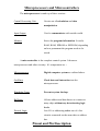
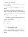
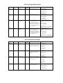
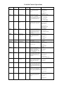
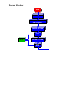
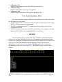
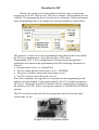
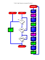
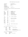
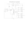
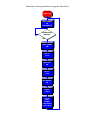
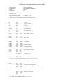
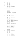
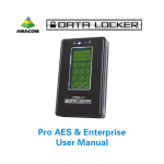
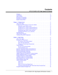
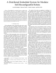
The Queen's University of Belfast
Dept. Electrical & Electronic Engineering
Programmable
Integrated
Controllers
from
Microchip
Written by :
Kieran McCormick
and
Mark Duncanson
(Electronics Workshop - Ashby Building)
Contents
1.
Introduction
2.
What is a PIC
3.
Development Flowchart
4.
Microprocessors & Microcontrollers
5.
Pinout & Pin description
6.
Commonly Used Commands
7.
More Advanced Commands
8.
Command List
• Byte-oriented instructions
• Bit-oriented instructions
• Variable/Control Operations
9.
Development of a Simple program
10.
From source code to Application
• MPASM (Microchip’s Assembler)
• MPSIM (Microchip’s Simulator)
• PROG84 (Software used to drive PIC programmer)
11.
Appendices
• (A) Example Applications
• (B) Book List
Introduction
The information Contained in this document has been put together to
provide a basic beginners guide to the Microchip’s Programmable Integrated
Controllers.
This is an introduction only, so not all features will be included. In this
document, we have based our work on the PIC16C84, as it is an EEPROM
enabling easy re-programming. Programming and re-programming is made very
simple with as little external hardware as possible. Most commands are common
to all the PICs, although, you should refer to Microchips Databook for finer
details
This document should enable the reader to write and test a simple program
and then program the PIC16C84 to carry out this operation.
What is the PIC
PIC stands for Programmable Integrated Controller, a complete
microcontroller built into an integrated circuit. It can be used for numerous
applications, where control is required, whether it be automated or manual.
Examples include Traffic Light Controllers and Car Indicator Timers.
The PIC can be programmed, on computer, using assembly language and
assembled using MPASM, Arizona Microchip’s PIC Assembler. This is to be
used to encode the PIC with a programmer connected to your printer port on the
computer. When the PIC is programmed, it should be able to control operations
external to the computer or programmer, on it’s own, providing all hardware is
correctly set up.
A simulator program for PICs is also available, MPSIM, which allows you
to single step programs while examining the registers and counter, etc., on the
screen. This is a vital tool for debugging your program and ensuring that you are
satisfied with it’s performance. Some PICs are not easily erasable, so it is cost
effective to test your program before pre-programming the PIC.
Development Flowchart
CONCEPT
Hardware
Design
Software
Design
Assemble
software
MPASM
Simulate
MPSIM
PIC in circuit
emulator
BUG FREE?
YES
Program PIC
PIC Programmer
Test in Circuit
NO
Microprocessors and Microcontrollers
The microprocessor is made up of three section:-
Central Processing Unit
Carries out all calculation and data
manipulation.
Input/Output
Used to communicate with outside world.
Memory
Stores the program information. It can be
RAM, ROM, EPROM or EEPROM, depending
on how permanent the program needs to be
stored.
A microcontroller is the complete control system. It houses a
microprocessor and other circuitry. It’s components are :-
Microprocessor
Digital computer system as outlined above.
Oscillator
Clock data and instruction into the
microprocessor.
Watchdog Timer
Prevents system latchup.
Buffering
Allows address and data busses to connect to
many chips without any deteriorating logic
levels.
Decode Logic
Lets I/O or addressing select one of a few
circuits connected on the same data or address
bus.
Pinout and Pin Description
Pin Names
Description
RA0 - RA3 -
Lower 4 bits of Port A, Bi-directional (TTL input level)
RA4/TOCK1
5th bit of Port A Open Collector Input/Output (Also
clock I/P to TMR0)
RB0/INT
Low bit of Port B, Bi-directional/Ext. Interrupt Input
(TTL input level)
RB1 - RB7
_____
MCLR/Vpp
Upper 7 bits of Port B, Bi-directional (TTL input level)
Vss
Supply Voltage
Vdd
Supply Ground
OSC1/CLKIN
Clock Input/Oscillator Connection
OSC2/CLKOUT
Oscillator Connection or Clock Out in RC mode (RC is
internal)
Master Clear(external reset). Must be kept HIGH for
normal operation
Commonly Used Commands
As with any programming language, you must learn commands and how to
use them properly. The full instruction set for PIC16C84 is on page 2-569 of
1994 Microchip Databook.
Each command line has it's Mnemonic, (the operation to be performed),
and in most cases operands, (which are the details of registers or data to be
processed.)
The standard commands allow you to manipulate data which may be from
memory locations, working register or literal data, (actual numbers in the
program). The ability to add and subtract, use logic (AND, OR and XOR), move
data between locations and call subroutines are all available.
First we will look at the registers and some of the operand types and what
they mean.
f
-
Register file address (0x00 to 0x7F).
'f' can be any of the memory address locations between 0x00 and 0x7F. It
can be given a tag or name by entering an equate line,
register name EQU register location
Then rather than having to use the location in commands you may quote the name
you have given the register.
W
-
Working register.
'W' is also known as the accumulator. It is an 8-bit register used for all
ALU operations. It is NOT part of the data memory.
k
-
Literal field, constant data or label.
'k' is used where a literal number is to be used in a command line. It also
represents the name of a label, which may be used in a subroutine. You can put a
label before a command line when typing it in, so it will then be in the left hand
side of the screen. It is good practice to use a TAB before each line, so that you
can easily see where labels are. You should also TAB your spaces in the Program
File Editor.
(Commonly Used Commands continued)
d
-
Destination select; If d=0, store result in W, d=1 store result in f.
'd' can only be '1' representing 'f' or '0' representing 'W'. After an operation
has been done, in most cases you have the option of storing the result in the 'W'
register or 'f' register, depending on where you want the result stored.
Ex. 1
Adding the contents of W, the working register, with f, the address of a
memory register which is 07H, leaving the result in the working register.
Before instruction
W = 0x08
Command to use
-
Label
ADDWF
f,d
Add W and f
Mnemonic
Operand
Data
Comments
TOTALREG
EQU
07H
This gives location 07H a tag or name
"TOTALREG" (TOTALREG=07H)
ADDWF
TOTALREG,0
After instruction
Ex. 2
-
f = 0x04
W = 0x0C
Adds 'f' to 'W' and because of the '0' after the
comma the result is stored in 'W'
f = 0x04
Calling a subroutine called DELAY from a different part of the program.
Command to use
-
Label Mnemonic
Operand
COUNT
CALL
.
.
.
DELAY MOVLW
MOVWF
LOOP DECFSZ
next
GOTO
RETURN
CALL
RETURN
EQU 08
Data
k
Call subroutine
Return from subroutine
Comments
Gives 08 the tag COUNT
DELAY
.
.
.
Looks for label DELAY anywhere in the program
FF
Puts FF into W register
COUNT
Puts contents of W into COUNT
COUNT,1
Decrements COUNT leaving result in COUNT (Skip
line if result is Zero)
LOOP
Loop back up to previous line LOOP
Return from subroutine to next instruction after CALL
DELAY
More Advanced Commands
Below there are some examples of the use of slightly more unusual
commands.
Ex.3
Use the AND command to identify common bits in two different memory registers 11H and
12H. The result is to be stored in memory register 13H.
The contents of one of the registers must be put in the W register so that the ANDWF
instruction can be used. Then use the destination for the result as '0' (W register), so as not to change
the original memory register. Assume the following contents of 11H and 12H.
Before Instructions
11H = A3
12H = 7C
(10100011)
(01111100)
AND Result expected
13H =
(00100000) or 20H
Label
Mnemonic
REG1
Operand
EQU
11H
Data
Comments
Name Register 11H with REG1
REG2
EQU
Register 12H with REG2
RESULT
EQU
MOVF
REG1,0
13H
12H
Name
Name Register 13H with RESULT
Moves contents of REG1 (A3) into W
register
(dest. is W indicated by Zero after comma)
ANDWF
REG2,0
Logic AND W reg. with REG2 (7C)
(dest. is W indicated by Zero after comma)
MOVWF
RESULT
contents into RESULT or loc. 13H
After Instructions
Moves W
11H = A3
12H = 7C
13H = 20H
Now let's look briefly at some other useful commands.
Instruction
RLF
Description
f,d
Example
RRF
f,d
Example
SWAPF
f,d
Example
Rotate left register f through carry to destination, d. To rotate within the
register f use the number 1 for d.
Before f = 11101101
carry = 0 After f = 11011010
carry = 1
Rotate right register f through carry to destination, d.
Before f = 11101101
carry = 0 After f = 01110110
carry = 1
Swaps halves of the 8 bit register f. Again d represents destination.
Before f = A7
After
f = 7A
Byte-oriented Instructions
Instruction
BCF
Syntax
BCF f,b
Description
Bit Clear f
Status
Affected
None
Action
Bit b in register f is reset to 0
Example
BCF FLAG_REG, 7
Before Instruction
FLAG_REG = 0xC7
BSF
BSF f,b
Bit Set f
None
Bit b in register f is reset to 1
After Instruction
FLAG_REG = 0x47
BSF FLAG_REG, 7
Before Instruction
FLAG_REG = 0x0A
BTFSC
BTFSC f,b
Bit Test,
Skip if Clear
None
If bit b in register f is 0 then the
next instruction is skipped.
If bit is 0 the next instruction,
fetched during current instruction
execution, is discarded and a NOP
is executed instead making this a
two cycle instruction
BTFSS
BTFSS f,b
Bit Test,
skip if Set
None
If bit b in register f is 1 then the
next instruction is skipped.
If bit is 1 the next instruction,
fetched during current instruction
execution, is discarded and a NOP
is executed instead making this a
two cycle instruction
After Instruction
FLAG_REG = 0x8A
HERE BTFSC FLAG, 1
FALSE GOTO PROCESS_CODE
TRUE...
Before Instruction
PC = address HERE
After Instruction
if FLAG<1> =0, PC =address TRUE
if FLAG<1> =1, PC =address FALSE
HERE BTFSS FLAG, 1
FALSE GOTO PROCESS_CODE
TRUE...
Before Instruction
PC = address HERE
After Instruction
if FLAG<1> =1, PC =address TRUE
if FLAG<1> =0, PC =address FALSE
Bit-oriented Instructions
Instruction
ADDWF
ANDLW
ANDWF
CLRF
Syntax
ADDWF f,d
ANDLW f,d
ANDWF f,d
CLRF f
Description
Add w to f
AND Variable and W
AND W and f
Clear f
Status
Affected
C, DC, Z
Z
Z
Z
Action
Add the contents of the W register
to register f. If d is 0 the result is
stored in the W register. If d is 1
the result is stored band in register
f.
The contents of the W registers are
ANDed with the 8-bit variable k.
The result is placed in the W
register
AND the W register with register f.
If d is 0 the result is stored in the
W register. If d is 1 the result is
stored back in register f.
The contents of register f are
cleared and the Z bit is set
Example
ADDWF FSR, 0
Before Instruction
W = 0x17
FSR = 0xC2
After Instruction
W = 0xD9
FSR = 0xC2
ANDLW 0x5F
Before Instruction
W = 0xA3
After Instruction
W = 0x03
ANDWF FSR, 1
Before Instruction
W = 0x17
FSR = 0xC2
After Instruction
W = 0x17
FSR = 0x02
CLRF FLAG_REG
Before Instruction
FLAG_REG = 0x5A
After Instruction
FLAG_REG = 0x00
Z=1
CLRW
CLRW
Clear W Register
Z
W register is cleared. Zero bit (Z)
is set.
CLRW
Before Instruction
W = 0x5A
COMF
DECF
DECFSZ
INCF
INCFSZ
COMF f,d
DECF f,d
DECFSZ
INCF f,d
INCFSZ f,d
Complement f
Decrement f
Decrement f,
skip if 0
Increment f
Increment f,
skip if 0
Z
Z
None
Z
None
The contents of register f are
complemented. If d is 0 the result
is stored in W. If d is 1 the result is
stored back in register f
Decrement register f. If d is 0 the
result is stored in the W register. If
d is 1 the result is stored back in
register f.
The contents of register f are
decremented. If d is 0 the result is
placed in the W register. If d is 1
the result is placed back in register
f.
If result is 0, the next instruction,
which is already fetched, is
discarded. A NOP is executed
instead making it a two-cycle
instruction
The contents of register f are
incremented. If d is 0 the result is
placed in the W register. If d is 1
the result is placed back in the
register f.
The contents of register f are
incremented. If d is 1 the result is
placed back in register f.
If the result is 0, the next
instruction, which is already
fetched is discarded. An NOP is
executed instead
IORWF
MOVF
MOVWF
IORWF f,d
MOVF f,d
MOVWF f
Inclusive OR W with
f
Move f
Move W to f
Z
Z
None
Inclusive OR the W register with
register f. If d is 0 the result is
stored in the W register. If d is 1
the result is stored back in register
f.
The contents of register f is moved
to destination d. If d=0 destination
is W register. If d=1, the
destination is file register f itself.
d=1 is useful to test a file register
since status flag Z is affected.
Move data from W register to
register f.
After Instruction
W = 0x00
Z=1
COMF f.d
Before Instruction
REG1 = 0x13
After Instruction
REG1 = 0x13
W = 0xEC
DECF f,d
Before Instruction
CNT = 0x01
Z=0
After Instruction
CNT = 0x0o
Z=1
HERE DECFSZ CNT, 1
GOTO LOOP
CONTINUE...
Before Instruction
PC = address HERE
After Instruction
if CNT = 0, PC = address CONTINUE
if CNT <> 0, PC = address HERE + 1
INCF CNT,1
Before Instruction
CNT = 0xFF
Z=0
After Instruction
CNT = 0x00
Z=1
HERE INCFSZ CNT, 1
GOTO LOOP
CONTINUE...
Before Instruction
PC = address HERE
After Instruction
CNT = CNT + 1
if CNT = 0, PC = address CONTINUE
if CNT <> 0, PC = address HERE + 1
IORWF RESULT, 0
Before Instruction
RESULT = 0x13
W = 0x91
After Instruction
RESULT = 0x13
W = 0x93
MOVF f,d
After Instruction
W = value in FSR register
MOVWF OPTION
Before Instruction
OPTION = 0xFF
W = 0x4F
NOP
NOP
No Operation
None
No operation
After Instruction
OPTION = 0x4F
W = 0x4F
NOP
RLF
RRF
SUBLW
RLF f,d
RRF f,d
SUBLW k
Rotate Left f
through carry
Rotate Right f
through carry
Subtract W from
Variable
C
C
C, DC, Z
The contents of register f are
rotated 1-bit to the left through the
Carry Flag. If d is 0 the result is
placed in the W register. If d is 1
the result is stored back in register
f.
The contents of register f are
rotated 1-bit to the right through the
Carry Flag. If d is 0 the result is
placed in the W register. If d is 1
the result is stored back in register f
The W register is subtracted (two’s
complement method) from the 8bit variable k. The result is placed
in the W register
RLF REG1, 0
Before Instruction
REG1 = 11100110
C=0
After Instruction
REG1 = 11100110
W = 11001100
C=1
RRF REG1, 0
Before Instruction
REG1 = 11100110
C=0
After Instruction
REG1 = 111001100
W = 01110011
C=1
SUBLW 0x02
Before Instruction
W=1
C=?
After Instruction
W=1
C = 1; result is positive.
SUBWF
SWAPF
XORWF
SUBWF f,d
SWAPF f,d
XORWF f,d
Subtract W from f
Swap f
Exclusive OR W
with f
C, DC, Z
None
Z
Subtract (two’s complement
method) the W register from
register. If d is 1 the result is stored
back in register f.
The upper and lower nibbles of
register f are exchanged. if d is 0
the result is placed in W register. If
d is 1 the result is placed in register
f.
Exclusive OR the contents of the
W register f. If d is 0 the result is
stored in the W register. If d is 0
the result is stored in the W
register. If d is 1 the result is stored
back in register f.
If result is negative C = 0
SUBWF REG1, 1
Before Instruction
REG1 = 0
W=1
C = 0; result is negative
After Instruction
REG1 = FF
W=1
C=0
SWAPF REG, 0
Before Instruction
REG = 0xA5
After Instruction
REG = 0xA5
W = 0xA5
XORWF REG, 1
Before Instruction
REG = 0xAF
W = 0xB5
After Instruction
REG = 0x1A
W = 0xB5
Variable/Control Operations
Instruction
ADDLW
CALL
CLRWDT
GOTO
IORLW
Syntax
ADDLW k
CALL k
CLRWDT
GOTO k
IORLW k
Description
Add Variable to W
Subroutine call
Clear Watchdog
Timer
Branch
Inclusive OR
Variable with W
Status
Affected
C, DC, Z
None
TO, PD
None
Z
MOVLW
MOVLW k
Move Variable to W
None
OPTION
OPTION
Load OPTION
register
None
RETFIE
RETLW
RETURN
RETFIE
RETLW k
RETURN
Return from Interrupt
Return Variable to W
Return from
Subroutine
None
None
None
SLEEP
SLEEP
SLEEP Mode
TO, PD
TRIS
TRIS f
Load TRIS register
None
XORLW
XORLW k
Exclusive OR
variable with W
Z
Action
The contents of the W register are
added to the 8-bit variable k and
the result is placed in the W
register.
Subroutine call. First, return
address (PC+1) is pushed on to the
stack. The 11-bit immediate
address is loaded into PC bits 0 to
10. The remaining upper bits of the
PC are loaded from PCLATH
(f03).
CLRWDT instruction resets
Watchdog Timer. It also resets the
prescaler of WDT. Status bits are
set
GOTO is an unconditional branch.
11-bit immediate value is loaded
into PC bits 0 to 10. Upper PC bits
are loaded from bits 3 and 4 of
PCLATH. GOTO is a two cycle
instruction
The contents of the W register are
OR’ed with the 8-bit variable k.
The result is placed in the W
register
The 8-bit variable k is loaded into
the W register
The contents of the W register is
loaded into the OPTION register.
This instruction is only supported
by the PIC16C84
Return from interrupt. Stack is
popped and Top Of Stack (TOS) is
loaded in PC. Interrupts are
enabled by setting the GIE bit
(INTCON register, bit 7). This is a
two cycle instruction
The W register is loaded with the
8-bit variable k. The PC is loaded
from the top of the stack - the
return address. This is a two cycle
instruction
Return from subroutine. The stack
is popped and the top of the stack
(TOS) is loaded into the program
counter. This is a two cycle
instruction.
SLEEP mode. Power down status
bit (PD) is cleared. Time-out status
bit (TO) is set. Watchdog Timer
and Prescaler are cleared. Processor
is put into SLEEP Mode with clock
stopped.
The contents of the W register is
loaded into the control register f,
where f = 5,6 or 7. This Instruction
is only supported by the PIC16C84.
The contents of the W register are
XOR’ed with the 8-bit variable k.
The result is placed in the W
register
Example
ADDLW 0x15
Before Instruction
W = 0x10
After Instruction
W = 0x25
HERE CALL THERE
Before Instruction
PC = address HERE
After Instruction
PC = address THERE
TOS = address HERE
CLRWDT
Before Instruction
WDT counter = ?
After Instruction
WDT counter = 0x00
WDT prescaler = 0
TO = 0; PD = 0
GOTO THERE
After Instruction
PC = address of THERE
IORLW 0x35
Before Instruction
W = 0x9A
After Instruction
W = 0xBF
MOVLW 0x5A
W = 0x5A
OPTION
Before Instruction
OPTION = ?
After Instruction
OPTION = W
RETFIE
After Interrupt
PC = TOS
GIE = 1
RETLW
Before Instruction
W = ?; PC = ?
After Instruction
W = k; PC = return address
RETURN
After Interrupt
PC = TOS
SLEEP
TRIS f
Before Instruction
f=?
After Instruction
f=W
XORLW 0xAF
Before Instruction
W = 0xB5
After Instruction
W = 0x1A
Development of a Simple Program
Now you can see how to develop a program from an idea.
Example
Two alternately flashing LED's are required for this simple program. The
delay between them changing is to be noticeable but not slow.
What things are needed to do this?
1.
Two separate Bits need to be assigned as outputs from the PIC.
2.
A delay of less than 1 second but more than 0.1 seconds is needed.
3.
LED A has to be HIGH and LED B has to be LOW, for one DELAY.
4.
LED B has to be HIGH and LED A has to be LOW, for one DELAY.
5.
Jump back to 3 and keep repeating.
What needs to be set up?
1.
PortB bits 0 and 1 can be setup as LED A and LED B respectively.
2.
The label PORTB can be put on Location 06H
3.
Real Time Clock Counter Register (RTCC) is at 01H
4.
Timer Counter, COUNT set to 00H
5.
TIME set to 00H
Program Flowchart
START
SETUP VARIABLES
SET PORT B AS OUTPUT
AND CLEAR PORT
ON LEDA / OFF LEDB
CALL
DELAY
DELAY
OFF LEDA / ON LEDB
CALL
DELAY
Program
; Alternating LEDs routine - Filename:
; Stephen Waddington
;Set variables
PORTB
RTCC
COUNT
TIME
EQU
EQU
EQU
06H
01H
EQU
08H
;
;
00H
;
ledonoff.asm
PORTB is register 6
PIC RTCC timer register
;
Timer counter
Timer period
; Initialisation routine
INIT
ORG
TRIS
CLRF
00H
PORTB
PORTB
;
;
;
Store program at location 00H
Set PORTB as outputs
Clear PORTB
; Main program
MAIN MOVLW
MOVWF
CALL
MOVLW
MOVWF
CALL
GOTO
B'00000001'
PORTB
DELAY
B'00000010'
PORTB
DELAY
MAIN
;
Set LEDA on, LEDB off
;
;
Hold LEDA on for .256ms
Set LEDB on, LEDA off
;
Hold LEDB on for .256ms
; Delay routine
DELAY CLRWDT
MOVLW
MOVWF
CLRF
LONG BTFSC
GOTO
GOTO
JUMP CLRF
DECFSZ
;
Clear Watchdog timer
TIME
COUNT
RTCC
RTCC,7
JUMP
LONG
RTCC
COUNT,F
;
;
;
;
;
;
;
;
;
;
Clear RTCC register
Test RTCC bit 7(128 x 256us = 32.768us)
If RTCC bit 7 set goto JUMP
If RTCC bit 7 not set then loop until set
If RTCC bit 7 set then clear RTCC
Decrement COUNT by 1 until zero
(32ms x 8 = 0.256s)
Loop LONG if COUNT <> zero
Return to call location
On RESET goto INIT
GOTO
RETURN
RESET GOTO
END
LONG
INIT
From Source Code to Application
Once you have written the program code for your application it will need to be
tested and possibly debugged. This can be done in one of three ways
• In Circuit Emulator (ICE)
• Software Simulation
• Download to PIC
In Circuit Emulator (ICE)
This is a device which plugs into your target circuit and is controlled by the
computer and allows real-time testing of the program code. This method carries a
cost as in most cases a different ICE is needed for the different families of the
PIC and the ICEs start at about approx. £500
Example For An In Circuit Emulator
Software Simulation
MicroChip have produced MPSIM which enables PIC code to be emulated
by a PC and various program variables, interrupts, and ports to be monitored.
Download to PIC
The final method is to download the code to the PIC that is intended for
final use. This method is the most commonly used as you can try the code in the
target circuit in real-time without the expense of an ICE.
Assembling the Code
Before you can test the code it has to be assembled from its ASCII format
file to a hexadecimal format which can be simulated or downloaded. An In
Circuit Emulator may need hexadecimal code but some types will work with just
the ASCII format code.
There are various assemblers available. The most common is MPASM
which is provided by MicroChip, this is needed to create code for MPSIM and
various download software. Another assembler produced by MicroChip is
MPALC which is required by some download programs.
MPASM
MPASM is a DOS based program that accepts source code in a standard
ASCII format and allows the user to select the required output format on screen.
It also has a reasonable level of error reporting for when things inevitably don’t
go right first time. MPASM’s main screen looks as follows:
Use of MPASM
1. Enter the name of the source file (Code in ASCII Format) i.e. [ledonoff.asm]
2. Select type of processor i.e. PIC16C84
3. Select the Hex output format i.e. INHX8M (The assembler is able to create
four different Hex output formats, depending on the format required by the
PIC programmer.)
4. By default the assembler is set to output an Error file and Listing file so to
start the assembler simply press [F10]
The assembler returns a series of statistics relating to the length of the length of
the assembled code as well as the number of warning and error messages. If the
code contains any bugs it will not run when downloaded to the PIC. Errors
reported in either the List or Error files. The creates two other in addition to the
list and error files. These are as follows:
• <filename>.asm
Default source code file
• <filename>.lst
Default output extension for listing files generated from the assembler
• <filename>.err
Default output extension from MPASM for error details.
• <filename>.hex
Default output code for porting to target PIC
• <filename>.cod
Default output extension for the symbol and debug file.
In Circuit Emulator (ICE)
In circuit emulators operate differently depending on the make and model
but the basic use is the same:
1. A lead from the ICE is connected to the IC socket on the target circuit where
the PIC will be going once programmed.
2. The ICE is connected to the PC, in most cases this is done via the serial
communication port.
3. The ICE software is then run on the PC which takes your program code and
makes the ICE run like the programmed PIC in real time.
MPSIM
Like the MicroChip assembler MPASM, MPSIM is DOS based and as
such, is not very user friendly. It uses a set of proprietary instructions to both
initialise the simulator environment and run an actual simulation. It’s almost as if
you need to learn an additional software language before you can run a
simulation. For this reason, the majority of people tend to test software by
downloading it directly to the target PIC. The MPSIM main screen looks as
follows:
MPSIM is supplied with a comprehensive user manual in an ASCII format text
file.
Download to PIC
Whether for testing or for final production the last stage is to place the
program on to the PIC ready for use. There are a number of programming devices
available. The programming device consists of two elements, a software program
and a programming board. An example of a software program is shown below:
The software is used to drive the programming board which in most cases holds
the PIC for programming in a zero insertion force (ZIF) socket.
Programming a PIC is Very straightforward. Having load the programmer
application and connected the programming board the following information is
selected.
• Program source code. (i.e. ledonoff.hex)
• The file format that the source code is in (i.e. INHX8M)
• The type of oscillator being used on the target circuit
• The PICs software fuses that need to be set
Once this is complete, the target device is mounted on the programming board
and the code downloaded. It takes approximately 20 to 30 seconds to program a
PIC device. During this time the PC transfers the hex code and fuse selections to
the memory of the PIC, before verifying the contents of all EPROM or EEPROM
memory.
The PIC can now be removed from the programmer and placed in the target
circuit ready for use.
Example Of a PIC Programmer Board
Appendix (A)
Example Applications
Traffic Light Sequencer
This traffic light sequencer could be used as part of a model railway set or with
slight modification be scaled up for roadside use.
The basic unit steps through its sequence either manually or at a fixed speed. For
home use, the speed of 5 seconds between step is probably adequate. In the auto
mode, the lights continually sequence. The manual mode changes the lights from
one direction of traffic flow to the other enabling the standard ‘road work’
operation or a 4 way junction.
To enable the design to be used commercially, a variable time control could be
added to change the duration between changeover sequences. The design would
then run on a 16C71, 73 or 74 and the various time settings in an analog form
could be read and converted to actual times within the software.
The light sequence is set in the software and follows the standard “Red - Yellow
- Green - Green & Yellow - Red” pattern. Modification of the software for 3 way
junctions can easily made by increasing the number of blocks of light patterns
with their associated delays.
Traffic Light Sequencer (program flowchart)
INITALISE
PORTS & RTCC
RED1=0
GRN1=1
DLY1
DELAY
CALL
DELAY
YEL1=1
GRN2=0
YEL2=1
YES
AUTO
?
CALL
DLY1
NO
DELAY
5S
STEP
PRESS
NO
YEL1=0
RED1=0
GRN1=1
RED2=1
YES
CALL
DELAY
STEP
RELEASED
NO
GRN1=0
YEL1=1
YEL2=1
YES
CALL
DLY1
RETLW 0
YEL1=1
YEL2=0
RED2=0
CALL
DLY1
Traffic Light Sequencer (source code)
; WRITTEN BY
; COPYRIGHT
; DATE
; ITERATION
; FILE SAVED AS
; FOR PIC16C54
; 4.00 MHz RESONATOR.
; INSTRUCTION CLOCK
NIGEL GARDNER
BLUEBIRD ELECTRONICS
21/2/95
1.0
TRAF1.ASM
1.00 MHz T= 1uS
; SOFTWARE WRITTEN FOR USE WITH PROJECT BOARD FROM BLUEBIRD
; ELECTRONICS.
; ***** EQUATES *****
RTCC
PC
STATUS
CARRY
DCARRY
PDOWN
WATDOG
FSR
Z
EQU
EQU
EQU
EQU
EQU
EQU
EQU
EQU
EQU
1
2
3
0
1
3
4
4
2
; COUNTER
; PROGRAM COUNTER
; STATUS REGISTER
; CARRY BIT
; DIGIT CARRY BIT
; POWER DOWN BIT
; WATCHDOG TIMEOUT BIT
; FILE SELECT REGISTER
TIME
EQU
.156
; 156 * 64mS = 10 SECONDS
PORTA
AUTO
STEP
EQU
EQU
EQU
5
0
1
; MANUAL AUTO SWITCH
; SEQUENCE STEP SWITCH
PORTB
RED1
YEL1
GREEN1
RED2
YEL2
GREEN2
EQU
EQU
EQU
EQU
EQU
EQU
EQU
6
0
1
2
3
4
5
COUNT
EQU
0BH
ORG
00
; SET A OF LIGHTS
; SET B OF LIGHTS
; GENERAL PURPOSE COUNTER
; *********** INITALISE PORTS AND RTCC *************
INIT
MOVLW
TRIS
CLRF
MOVLW
TRIS
MOVLW
OPTION
00H
PORTB
PORTB
0FH
PORTA
B'00000111'
; PORT B AS OUTPUTS
; PORT A AS INPUTS
; RTCC PRE-SCALAR /256
; 256uS PER COUNT INTERNAL CLOCK
; ********* PROGRAM BEGINS HERE **********************
MAIN BSF
BSF
MOVLW
CALL
PORTB,RED1
PORTB,GREEN2
TIME
; DELAY TIME
DELAY
BSF
BCF
BSF
MOVLW
CALL
PORTB,YEL1
PORTB,GREEN2
PORTB,YEL2
TIME
; DELAY TIME
DELAY
BCF
BCF
BSF
BSF
MOVLW
CALL
PORTB,YEL1
PORTB,RED1
PORTB,GREEN1
PORTB,RED2
TIME
; DELAY TIME
DELAY
BCF
BSF
BSF
MOVLW
CALL
PORTB,GREEN1
PORTB,YEL1
PORTB,YEL2
TIME
; DELAY TIME
DELAY
BCF
BCF
BCF
GOTO
PORTB,YEL1
PORTB,YEL2
PORTB,RED2
MAIN
; TEST HERE TO SEE IF MANUAL MODE OR DELAY IF AUTOMATIC
DELAY BTFSC
GOTO
LP1
BTFSC
GOTO
LP2
BTFSS
GOTO
RETLW
PORTA,AUTO
DLY1
PORTA,STEP
DELAY
PORTA,STEP
LP2
0
; TEST FOR AUTO SWITCH ON
; AUTOMATIC MODE
; IF MANUAL MODE, THEN WAIT FOR
; BUTTON PRESS BUT CHECK IF AUTO
; AND THEN RELEASE BEFORE CONTINUING
; TO NEXT SEQUENCE
; LONG DELAY 64mS * VALUE IN W REGISTER
DLY1
CLRF
MOVWF
LONG2 BTFSC
GOTO
GOTO
RTCC
COUNT
RTCC,7
JMP1
LONG2
JMP1
CLRF
DECFSZ
GOTO
RETLW
RTCC
COUNT,F
LONG2
0
; YES, SO CLEAR RTCC
; DECREMENT, UNTIL ZERO
ORG
GOTO
END
1FFH
INIT
; RESET VECTOR FOR C54
; USE THIS REGISTER TEMPORARILY
; TEST RTCC BIT 7 64*256uS = 64mS
; LOOP UNTIL BIT IS SET
Traffic Light Sequencer (circuit diagram)
Pedestrian Crossing Simulator
This code is similar to the traffic light sequencer in that it follows the sequence f
change from one set of lights to another. However, the addition of sound and
flash operation enables this design to become a fully working product with
minimal change.
The sounder shown in the diagram is a small loudspeaker. The warning tone
frequency is set within the software.
Modification to the design could be to include a delay between cycles to allow
sensible traffic flow or the provision of a vehicle sensor to allow faster response
times when no vehicles are present.
Pedestrian Crossing Simulator (program flowchart)
INITALISE
TRAF GREEN
ON
PED RED ON
NO
PEDESTRIAN
WAITING
YES
TRAF AMBER
ON
DELAY
1.47 S
TRAF RED
ON
DELAY
1.15 S
PED GREEN
ON
BLEEP
5 SECS
FLASH
TRAF
AMBER
PED GREEN
FOR 7 SECS
Pedestrian Crossing Simulator (source code)
; WRITTEN BY
; COPYRIGHT
; DATE
; ITERATION
; FILE SAVED AS
; FOR PIC16C54
; 4.00 MHz RESONATOR.
; INSTRUCTION CLOCK
NIGEL GARDNER
BLUEBIRD ELECTRONICS
2/8/95
1.0
PED1.ASM
1.00 MHz T= 1uS
; Software will run with project board from Bluebird Electronics
; ***** equates *****
rtcc
pc
status
carry
dcarry
pdown
watdog
fsr
z
equ
equ
equ
equ
equ
equ
equ
equ
equ
1
2
3
0
1
3
4
4
2
; counter
; program counter
; status register
; carry bit
; digit carry bit
; power down bit
; watchdog timeout bit
; file select register
time2
equ
.200
; 200*512us = 0.1024S
porta
#define
equ
go
5
porta,0 ; start button
portb
#define
#define
#define
#define
#define
#define
equ
red1
yel1
grn1
red2
grn2
buzz
6
portb,0 ; traffic lights
portb,1
portb,2
portb,3 ; pedestrian lights
portb,4
portb,7 ; buzzer for warning
count
sound
flash
equ
equ
equ
0ch
0dh
0eh
list p=16c54
org
; general purpose counter
; processor type
00
; ******************* subroutines *************************
; ********* long delay 32ms * value in w register *********
delay1
long2
jmp1
clrf
movwf
btfsc
goto
goto
rtcc
count
rtcc,7
jmp1
long2
clrf
decfsz
goto
retlw
rtcc
; yes, so clear rtcc
count,f ; decrement, until zero
long2
0
; use this register temporarily
; test rtcc bit 7 (128*256us = 32.768ms)
; loop until bit is set
; ***** delay with sounder of 1.95KHz ************
delay2
dly2
long3
jmp2
movlw
clrf
movwf
bsf
btfsc
goto
goto
bcf
clrf
decfsz
goto
retlw
time2
rtcc
count
buzz
rtcc,1
jmp2
long3
buzz
rtcc
count,f
long3-1
0
; load timer
; use this register temporarily
; test rtcc bit 1 (2*256us = 512us)
; loop until bit is set
; yes, so clear rtcc
; decrement, until zero
; *********** initalise ports and rtcc *************
init
clrf
movlw
tris
movlw
tris
movlw
option
portb ; clear port
00h
portb ; port b as outputs
0fh
porta
; port a as inputs
b'00000111'
; rtcc pre-scalar /256
; 256us per count internal clock
; ********* program begins here **********************
main
bleep
get_off
bsf
bcf
bsf
bcf
btfsc
goto
bcf
bsf
movlw
call
bsf
bcf
movlw
call
bcf
bsf
movlw
movwf
grn1
red1
red2
grn2
go
$-1
grn1
yel1
.45
delay1
red1
yel1
.35
delay1
red2
grn2
.30
sound
; traffic on green
movfw
call
movlw
call
decfsz
goto
sound
delay2
2
delay1
sound,f
bleep
; reload for next bleep
; 0.1S tone burst
; delay time
; 65mS quiet period
; count down time
; make sound again
; pedestrian on red
; loop for start button
; traffic on amber
; delay time (1.47S)
; traffic on red - wait for them to stop
; delay time (1.15S)
; pedestrian on green
; tone bursts approx 5 secs
movlw .9
movwf flash
; flash for approx 7 secs
movfw
movlw
call
bcf
bcf
bcf
movlw
call
bsf
bsf
; reload for next time
; 0.393S off
flash
.12
delay1
red1
yel1
grn2
.12
delay1
yel1
grn2
; turn off traffic red
; 0.39S on
; flash traffic amber
; flash pedestrian green
decfsz
goto
bcf
goto
flash,f
get_off
yel1
main
; count down
; get off xing
; turn off traffic amber
; go again
org
goto
1ffh
init
; reset vector for c54
end
Pedestrian Crossing Simulator (circuit diagram)
Book List
MicroChip DataBooks available from Electronics Store Rm. 10.4 (PIC Related)
• A Beginners Guide to the Microchip PIC (Nigel Gardner)
• PIC Cookbook - Vol. 1 (Nigel Gardner + Peter Birnie)
• PIC16/17 Microcontroller Databook
• Embedded Control Databook 1994/95