1
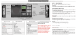
PROFESSIONAL LED BOOSTER USER MANUAL
BL-02
KEEP THIS MANUAL FOR FUTURE NEEDS
-1-
XM406-V1.0.1-NR
Thank you for your patronage. We are confident that our excellent products and service can
satisfy you. For your own safety, please read this user manual carefully before installing the
device.
In order to install , operate, and maintain the lighting safety and correctly. We suggest that the
installation and operation should be done by the verified technician and follow the instruction
strictly.
CAUTION!
Unplug mains lead before opening the housing.
1.INTRODUCTION:
Unpack the device. Inside the box you should find:
1. Manual
Please check carefully that there is no damage caused by transportation. Should there be any,
consult your dealer and don’t install this device.
BL-02 is a versatile function devices, which can receive and deal with two kinds of different
signals , than it follows DMX512 signal amplifier output. Signal input from the A, B two signal
port, can transpose to the 8 separate output ports or 4 a group, two sets of output ports 512
standard signal channel, but also have the the function of strengthen and amplifiy signal, each
output signal is independent , each of them has a separate source of information to provide a
signal without disturbing each other, each signal output port can be used alone or be used in
combination, even if a signal output port failure will not affect the normal use of the other output
port. BL-02 have three-pin and 5 pin Caron two models as per Caron. customers can buy with
their own use requirements.
-1-
XM406-V1.0.1-NR
2.Overview
1) Fuse
2) Power supply
3) Display
4) Indicator A
5) Indicator B
6)
Menu-button
7) Up-button
8) Enter-button
9) Down-button
10)A DMX in
11)B DMX in
12)DMX out
3.SAFETY INSTRUCTIONS
3.1) Important safety warns
This device has left the factory in perfect condition. In order to maintain this condition and to
ensure a safe operation, it is absolutely necessary for the user to follow the safety instructions
and warning notes written in this user manual.
Important:
Damages caused by the disregard of this user manual are not subject to warranty. The
dealer will not accept liability for any resulting defects or problems.
The electric connection must carry out by qualified person.
Make sure that the available voltage is not higher than stated at the end of this manual.
Make sure the power cord is never crimped or damaged by sharp edges. If this would be the case,
replacement of the cable must be done by an authorized dealer.
Always disconnect from the mains, when the device is not in use or before cleaning it. Only
handle the power cord by the plug. Never pull out the plug by tugging the power cord.
Please be aware that damages caused by manual modifications to the device are not
subject to warranty. Keep away from children and non-professionals.
-2-
XM406-V1.0.1-NR
3.2)GENERAL GUIDELINES
This fixture is only allowed to be operated with the max alternating current which stated in the
technical specifications in the last page of this manual.
Lighting effects are not designed for permanent operation. Consistent operation breaks may
ensure that the device will serve you for a long time without defects.
Do not shake the device.Avoid brute force when installing or operating the device.
While choosing the installation-spot, please make sure that the device is not exposed to extreme
heat, dust.
Operate the device only after having familiarized with its functions. Do not permit operation by
persons not qualified for operating the device. Most damages are the result of unprofessional
operation.
Please use the original packaging if the device is to be transported.
For safety reasons, please be aware that all modifications on the device are forbidden.
If this device will be operated in any way different to the one described in this manual, the
product may suffer damages and the guarantee becomes void. Furthermore, any other operation
may lead to short-circuit, burns, electric shock, lamp explosion, crash, etc.
For safty, plese turn to the authorised person for the maintaining in certain period. The wrong
installation or operation would be danger.
CAUTION!
Before taking into operation for the first time,
the installation has to be approved by an expert.
4.DMX-512 connection
Input the signal source to A, B, input ports and connect to the 8 output ports as per output needs
or selection mode , take note when input the two signal indicator which corresponding to the
input ports shows the input signal is stable or not, in order to avoid the output signaleffect.
-3-
XM406-V1.0.1-NR
5.Control Board
The Control Board offers several features: you can simply set the starting menu or make a reset.
[Menu]:Press this key to enter into edit mode. Press this key under the edit mode if you want to return to
previous menu. it will exit from edit mode 60 seconds after the last keypress
[UP]:Screen will flash when pressing this key in normal mode, the adress value will increasing. Keep
pressing this key, the address value will increase rapidly. it will exit from flash 60 seconds after the last
keypress. Press this key under edit mode, you can choose the function you want from the buttom up in the
menu.
[DOWN]:Screen will flash when pressing this key in normal mode, the adress value will idecreasing. Keep
pressing this key, the address value will decrease rapidly. it will exit from flash 60 seconds after the last
keypress. Press this key under edit mode, you can choose the function you want from the top down in the
menu.
[ENTER]:This key is functionless when in normal mode. Press this key under the edit mode, it will enter into
next menu.
Function
Mode
Set Dmx Address
Set Mode
Information
Product Info
Personality
A001~AXXX
No function,Split A->8, Split A->8 (hold),
Split 2->4, Split 2->4 (hold), Shifter A->4+4,
Merger HTP, Merger Shift, A backuped by B, B
backuped by A
Triton Blue
DMX Repeater
DMX address setting
Setup mode(0~9)
Product information
Software Version
Ver1.0.1……
Software version of
each IC
Reset Default
ON/OFF
Restore factory set.
Default settings shaded
1.FUNCTION MODE
1)Set DMX Address
With this function, you can adjust the desired DMX-address via the Control Board.
1. Access the main menu.
2. Tap the <Up/Down>button until“Set DMX Address”is displayed.
3. Press ENTER, the display will show “Set DMX Address”.
4. Tap the <Up/Down>button,the display will show “A001~AXXX”
5. Press ENTER to confirm or press <MODE/ESC> to return to the main menu.
2)Set Mode
1. Access the main menu.
2. Tap the <Up/Down>button until“Set Mode”is displayed.
3. Press ENTER, the display will show “Set Mode”.
4. The display show “Split A->8 (hold)”,Press <Up/Down>, the display will show
other.
5. Press ENTER to confirm or press <MODE/ESC> to return to the main menu.
-4-
XM406-V1.0.1-NR
2.Information
1)Product Info
1. Access the main menu.
2. Tap the <Up/Down>button until“Product Info”is displayed.
3. Press ENTER, the display will show “Product Info”.
4. The display show “Terbly BL-02”,Press <Up/Down>, the display will show “DMX
Repeater”.
5. Press ENTER to confirm or press <MODE/ESC> to return to the main menu.
2)Software Version Software version
With this function, you can display the software version of the device.
1.Tap <MODE/ESC>button,access the main menu,Tap the <Up/Down>button until
“Information”is displayed. Press ENTER, the display will show “Information”.
2.Press <Up/Down>, the display will show “Software version”.
3.Press< ENTER>, the display will show “Software version”.
4.The display show “Ver 1.0……”.
5.Press <ENTER> to confirm or press <MODE/ESC> to return to the main menu.
3. PERSONALITY
1) Restore Default
With this function, you can select restore factory set for ON or OFF, the default is OFF.
1.Tap <MODE/ESC>button,access the main menu,Tap the <Up/Down>button until
“Personality”is displayed. Press ENTER, the display will show “Personality”.
2.Press <Up/Down>, the display will show “Restore Default”.
3.Press< ENTER>, the display will show “Restore Default”.
4.The display show “OFF”,Press <Up/Down>, the display will show “ON”.
5.Press <ENTER> to confirm or press <MODE/ESC> to return to the main menu.
6、Operation model manual
1.No function: port 1~ 8 output 0
2.Split the A-> 8: A port for the signal input, do not use the B port; port 1~ 8 for signal output; when the input
signal have an error occurs, the port 1~ 8 output 0;
3.The Split A-> 8 (hold): function same with the Split A-> 8; when the input signal have an error occurs, ports
1 ~8 to keep the normal output
4.Split 2 -> 4: A port for the signal input, the corresponding port 1 ~ 4 for the signal output, when the A port
input signal have an error occurs, the port 1~ 4 outputs the 0B port
for signal input, the corresponding port 5 ~8 for the signal output; when the B port input signal have an error
occurs, the port 5~ 8 output 0;
5.Split 2 -> 4 (hold): function same with the Split 2 -> 4; when the input signal have an error occurs, ports 1
~8 to keep the normal output;
6.Shifter A, -> 4 +4: A ports for signal input, do not use the B port; port 1 ~ 4 output the original signal
directly, port 5 ~8 outputs the shift signal (the address value ‘s channel as the first channel output,the channel
-5-
XM406-V1.0.1-NR
after that follow same.
7.Merger HTP,: port 1~8 to port A and B in the same channel, the large value treat as a signal output;
8.Merger Shift: port 1 ~8 output ports A and B’s combined signal, the channel before the address value which
corresponding to the A port-channel is output, the channel begin the address value output the first channel of B
port, the channel after that follow same.
9.A, backuped by B: Port A signal output priority,
signal backup output for port B
10. B, backuped by A :signal B output priority signal backup output for Port A
11.Signal Indicator A, B, corresponding to indicates the port A, B, signal reception. When the signal light is
not on or flashing, indicating that the port no signal or poor reception; indicator lights stability, said signal
reception.
7.CLEANING AND MAINTENANCE
The following points have to be considered during the inspection:
1) All screws for installing the devices or parts of the device have to be tightly connected and
must not be corroded.
2) There must not be any deformations on the housing, color lenses, fixations and installation
spots (ceiling, suspension, trussing).
3) Mechanically moved parts must not show any traces of wearing and must not rotate with
unbalances.
4) The electric power supply cables must not show any damage, material fatigue or sediments.
Further instructions depending on the installation spot and usage have to be adhered by a skilled
installer and any safety problems have to be removed.
8.TECHNICAL SPECIFICATIONS
Power supply:AC 100-240V.50/60Hz;
Power consumption:10W
Net weight:2.2kgs
Gross weight:3kgs
Packing dimensions: 54x27x8cm
Remark: errors and omissions for every information given in this manual excepted. All
information is subject to change without prior notice.
-6-
XM406-V1.0.1-NR