
1
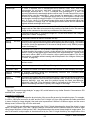
TETX, TETY, TETZ: Tolerance on element tilts
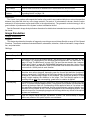
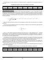
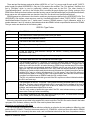
TETX, TETY, and TETZ are used to analyze tilts of either a surface or a lens group about the X, Y, or Z axes,
respectively. The two surface numbers defined by Int1 and Int2 indicate the beginning and ending surfaces of a
lens group. The min and max values are the tipping angles in degrees.
These tolerances require ZEMAX to insert a coordinate break surface before and after the lens group, and to
use a dummy surface at the end of the group to return to the front vertex. The entire group may then be pivoted
about a point as a unit. For this reason, TETX/Y/Z should not be used when the range of surfaces defined includes
a coordinate break which is related to a following coordinate break outside the surface range controlled by the
TETX/Y/Z by pickup solves. The hazard is if the two resulting tilt ranges overlap, then the position of the elements
may not be what is intended. If you require this capability, see the discussion on TUTX, TUTY, and TUTZ.
TETX and TETY may also be used to model tilt of single surfaces, sometimes called "wedge", like TSTX and
TSTY. TETX and TETY will work for surfaces of any type, including Standard surfaces and non-Standard
surfaces, while TSTX and TSTY only work for Standard surfaces. To tilt a single surface using TETX or TETY,
set Int1 and Int2 to the same surface number.
TETX and TETY by default pivot about the front vertex of a lens group, however it is often advantageous to
pivot about some other point. For example, well-designed lens mounts will pivot about the nodal point of a lens
to maintain focus during alignment. This case is easily modeled by ZEMAX through the use of a dummy surface
at the nodal point. Change the starting surf (Int1) to be at the nodal point dummy surface, and the pivoting will be
about that point. The first surface may be located anywhere with respect to the rest of the lens group; and so the
tilt may be about any point.
TETX, TETY, and TETZ operands may be nested. For example it is possible to analyze the tilt of one surface
group defined by surfaces 5 through 20; while simultaneously analyzing tilts of elements defined by surfaces 58, 8-12, 14-20, etc. This capability can simulate the alignment errors of elements within an assembly, as well as
the alignment error of the assembly as a whole. The nesting rules are fully described in the section “Nesting rules
for Monte Carlo analysis” on page 569.
TOFF: Tolerance off (can be used for comments)
This operand is a place holder that has no affect on the tolerance analysis. The TOFF operand may be used
to enter comments.
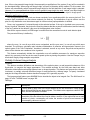
TUDX, TUDY, TUTX, TUTY, TUTZ: Tolerance on user defined tilts and decenters
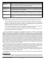
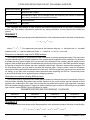
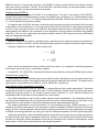
These five tolerances, TUDX, TUDY, TUTX, TUTY, and TUTZ, are used for more general user defined tilts
and decenters. The names are mnemonics for Tolerance User Decenter/Tilt X, Y, and Z. These are very similar
to the TEDX, TEDY, TETX, and TETY tolerances. The difference is that ZEMAX does not automatically insert the
required coordinate break surfaces to achieve the specified decenters and tilts in the tolerances. To use the
TUDX, TUDY, TUTX, TUTY, and TUTZ commands, you must have already defined the surface specified by Int1
to be a coordinate break surface. Normally, but not always, there will be a second coordinate break later in the
Lens Data Editor that has a pickup solve on the toleranced parameter. The pickup solve may be positive or
negative, as the case warrants. This permits some complex pivoting and decentering about arbitrary points, with
a certain finesse required. Min and max are in lens units for TUDX and TUDY, and in degrees for TUTX, TUTY,
and TUTZ, just like the coordinate break surface.
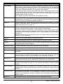
TNPS, TNPA, TNMA: Tolerances on non-sequential data
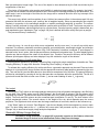
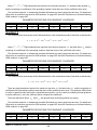
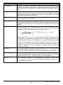
TNPS defines tolerances on Non-Sequential Component (NSC) data. Three integer parameters are required:
the NSC surface number (use 1 if the program mode is NSC), the object number, and a code. The code is 1, 2,
or 3 for the object’s X, Y, or Z position, respectively; the code is 4, 5, or 6 for the X-Tilt, Y-Tilt, or Z-Tilt, respectively.
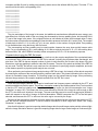
TNPA defines tolerances on NSC parameter data. The surface and object integers are defined in the same
way as for TNPS; the third integer is for the parameter number. See “NSC Objects” on page 481 for a detailed
explanation of what parameter numbers are used by which object types.
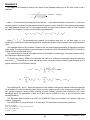
TNMA defines tolerances on the index Nd and Abbe Vd of NSC material data. Three integer parameters are
required: the NSC surface number (use 1 if the program mode is NSC), the object number, and a code. The code
is 1 or 2 for the material Nd and Vd values, respectively. When using TNMA, the change in the material index is
computed exactly as for the sequential glass offset solve, as described in “Glass: Offset” on page 478.
Chapter 19: TOLERANCING
554












































































































































































































































![Guida di SYNC™ HD - akmedia.[bleep]digidesign.](http://vs1.manualzilla.com/store/data/006124188_1-822f431325888ec14269d9216e9ac6fc-150x150.png)