1
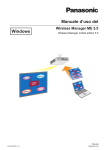
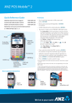
Valco Instruments Co. Inc.
Serial Valve Interface
Instruction Manual
svi.P65
Rev. 7/08
Printed in USA
North America, South America, and Australia/Oceania contact:
®
Valco Instruments Co. Inc.
tel: 800 367-8424
fax: 713 688-8106
[email protected]
Europe, Asia, and Africa contact:
®
VICI AG International
tel: + 41 41 925-6200
fax: + 41 41 925-6201
[email protected]
This page intentionally left blank for printing purposes
Table of Contents
General Description .............................................................................................. 1
Installation ............................................................................................................ 2
SVI Setup ...................................................................................................... 2
Interfacing the SVI to a PC ............................................................................ 3
Electric Actuator Connections ........................................................................ 4
Two Position Air Actuator Connections ........................................................... 5
SVI Control of Other Electrical Devices ......................................................... 5
Communicating with the SVI using VCom ............................................................. 7
Transmitted Command Types ......................................................................... 8
Transmitted Command Syntax ....................................................................... 8
Multiple Device Mode Commands .................................................................10
Responses Received from the SVI ............................................................... 11
Technical Drawings .............................................................................................. 12
Warranty ............................................................................................................. 17
This page intentionally left blank for printing purposes
1
General Description
The Valco Serial Valve Interface (SVI) is a device that converts commands
from a computer, via a serial port, into positional control for our two position
and multiposition valve actuators. Each SVI can control up to four air or
electrically actuated two position valves and two electrically actuated
multiposition valves. The SVI has two serial port connections (one male,
one female) which allow daisy-chaining of up to eight SVI’s on a single serial
communication port. In addition to controlling valves, the SVI can be used to
control other devices which require logic level BCD or single line inputs.
The SVI is a packaged unit which includes an external 12 VDC 200 MA wallmount power supply. There is no need to open the computer to connect the
SVI, because its DB-9 to DB-9 RS-232 cable connects to any available serial
port on the back of the computer. It also includes an interface cable for
Valco two position actuators, and two 20-pin IDC connectors for installation
on the interface cable which comes as part of the multiposition standard
electric actuator. For air actuated valves, optional interface cables are
available for the Valco Digital Valve Interface (DVI), which converts electrical
signals to pneumatic pulses. (Valco product number I-22239).
While the SVI can be operated by virtually any computer with an RS-232
port, the software supplied with this package is written for PC’s. The SVI is
supplied with Vcom software.
2
Installation
The Serial Valve Interface can be easily installed by the user with the
following items as supplied with the SVI:
• One wall-mount power supply
• One RS-232 cable, to interface the SVI to any PC/AT compatible serial
communications port with a DB-9 connector
Serial Valve Interface
Power supply
• One two-position interface cable for connecting up to four two-position
electric actuators or Digital Valve Interfaces for use with air actuators
• Two 20-pin IDC connectors, to adapt the external interface cables supplied
with Valco multiposition electric actuators for use with the SVI
• One CD with Vcom software.
RS-232 cable
NOTE: The jumpers referred to several times in the installation instructions
are small plastic connectors on the circuit boards which can be easily pulled
off and reinstalled on different pins.
SVI Setup
Two position
interface cable
20-pin IDC
connector
Valco Instruments Co. Inc.
The SVI can operate in one of two different modes, determined by the
position of the jumper on connector CO14 on the SVI main board during
power up. In the Option 1 position (the factory setting) the Single Device
Mode is selected; in the Option 2 position, the Multiple Device Mode is
selected. See Drawing 22110, page 14 for a complete list of the SVI jumper
options and the factory settings.
Single Device Mode
The single device mode, which is the factory-preset mode, requires a
dedicated Serial Communications Port on the host computer for each SVI.
Three optional baud rates can be selected by jumpers on the SVI main
board, with a factory setting of 9600 baud. See Drawing 22110, page 14.
Multiple Device Mode
Software CD
The multiple device mode allows up to eight SVIs to be daisy-chained from a
single serial communications port on the host computer. (Figure 1) In this
mode the SVI has a fixed 9600 baud rate. Connector CO11 on the SVI main
board selects an ID of 0 to 7 which is used to distinguish each device. (Each
SVI in the daisy chain must have a different ID.) The communications board
connector CO14 jumper must be changed to the PASS THRU position for all
SVIs on the daisy chain except for the last device, which should be set to
the END MODULE position to properly terminate the daisy-chain. See
Drawing 22110, page 14 for a complete list of the SVI jumper options.
Installation
3
CAUTION: For proper startup, make sure that all the
jumper settings in the SVI are correct, and that all external devices have been disconnected or are turned off
before applying power to the SVI.
Figure 1: SVIs daisy-chained to a single host computer
Interfacing the SVI to a PC
The SVI has two communication port connectors labeled “COM 1” and “COM
2”. The RS-232 cable provided connects the COM 1 connector on the SVI to
the serial port connector on the PC. If the computer serial port connector is
a DB-25 connector, then a DB-25 FEMALE to DB-9 MALE adapter connector
or cable is required. Most computer or electronic stores carry this adapter.
The RS-232 cable with Male and Female DB-9 connectors must be wired
“straight through”, or pin to pin; i.e., Pin 2 to Pin 2, Pin 3 to Pin 3, etc.
Only Pins 2, 3, and 5 are used by the SVI; they are functionally defined
as TRANSMIT, RECEIVE, and GROUND, respectively, from the SVI
perspective.
TWO POSITION
ELECTRIC ACTUATORS
INTERFACE CABLES
SUPPLIED WITH
MULTIPOSITION
ELECTRIC ACTUATORS
MULTIPOSITION
ELECTRIC ACTUATORS
HOST COMPUTER
TWO POSITION
INTERFACE CABLE
ANSLEY
CONNECTORS
RS-232 INTERFACE CABLE
Figure 2: SVI interconnection diagram
Installation
4
Electric Actuator Connections
Standard Two Position Electric Actuators
To connect the SVI to a two position standard electric actuator, use the two
position interface cable. Plug one end of this cable into the connector on the
top of the SVI which is labeled V1 V2 V3 V4. The other end of the cable has
four Molex connectors which are addressed by the SVI as V1 through V4.
These Molex connectors plug directly into the remote switching cable on the
back of Valco’s standard two position electric actuators.
Any Valco two position standard electric actuator with a serial number above
19000 allows the option of positive dual-position feedback to the SVI.
To enable this feature:
1. Unplug the actuator. Use a pair of pliers to compress and remove the
cable strain relief devices from the back of the actuator cover. Remove
them from the cables to allow the cables to travel freely through the holes
in the cover.
2. Remove the four phillips screws which secure the actuator cover.
(One must be accessed through a hole in the black mounting bracket)
3. Slide the cover back far enough to allow access to the small dipswitch
on the board next to the connectors for the manual switching cable, and
change the position of the switch.
4. Put the cover back in position, replace the four screws, and reinstall the
strain relief devices.
In this mode, the clear wire carries a logic high when the actuator is in
Position A (LOAD): the white wire carries a high when it’s in Position B
(INJECT).
Microelectric Two Position Actuators
Microelectric two position actuators have a built-in serial port, and
therefore do not require the SVI for serial port control. However, they
can be connected to an SVI if you are upgrading a system from standard
electric actuators and don’t want to change the existing SVI software.
Cable I-23196 adapts any of the Molex connectors (V1 through V4) on
cable I-22041 to the digital input port on a two position microelectric actuator.
If only two position microelectric actuators are to be used, then optional
cable I-23783, which provides four direct connections to the SVI, can be
substituted for cable I-22041.
Standard Multiposition Electric Actuators
Each standard multiposition electric actuator is shipped with an external
interface cable. This cable has an IDC 20-wire connector on one end, with
the other end unfinished to allow user-selected termination. To connect the
multiposition actuator to the SVI, install an IDC 20-wire connector on the
unfinished end. Plug one end of the cable into the multiposition electric
actuator and the other end into the connector on the SVI labeled either V5
or V6. Two multiposition valves may be used simultaneously.
Installation
5
Two Position Air Actuator Connections
The SVI can be used to control up to four Valco two position air-actuated
valves by connecting the SVI to the Valco Digital Valve Interface (DVI). The
two position electric actuator cable can be adapted to control a DVI using
this procedure:
1. Use a wire cutter to remove the plastic Molex connector from the SVI
connecting cable.
2. With a wire stripper, remove insulation from the red, blue, and black
wires in each of the DVI ribbon cables and the corresponding SVI ribbon
cable.
3. Use solder or crimp-on connectors to join the DVI ribbon cable to the SVI
ribbon cable as shown in the table below.
Valve
V1
V2
V3
V4
Signal
SVI wire color
DVI wire color
Pos A
Pos B
ground
Pos A
Pos B
ground
Pos A
Pos B
ground
Pos A
Pos B
ground
yellow
green
brown
yellow
green
brown
yellow
green
brown
yellow
green
brown
black
blue
red
black
blue
red
black
blue
red
black
blue
red
SVI Control of Other Electrical Devices
NOTE: The following information is not intended for users unfamiliar with low
power digital circuitry and proper isolation techniques.
The V1 PosA output on the SVI has special capabilities. While all other
two position outputs are transistor devices with 30 volt 50 milliamp (open
collector) outputs, the YELLOW wire (pin 4 of the Molex connector) on the
V1 output is a relay contact closure to ground. It can be used to drive loads
of up to 48 volts at 1/2 amp.
Additionally, the ground reference brown wire (pin 3 of the Molex) can be
jumpered on CO12 on the SVI main board for a 12 VDC output which is
sufficient to power small solenoids or other devices of up to 100 ma continuous current. (Or 200 ma on short duty cycle applications.) See Drawing
22110, page 14 for detailed information.
Installation
6
CAUTION: When the SVI Valve 1 output is jumpered for
12 VDC output, remove the plastic Molex connector
from the SVI cable to insure that damage will not result
from an accidental connection to a Valco two position
electric actuator or DVI.
Before using the valve outputs to drive any load in excess of 12 VDC, the
jumper on connector CO13 must be changed to the OFF position. This
effectively removes the internal 12 volt diode clamp on the two position
valve outputs, and requires the installation of external reverse diode clamping on all inductive loads driven by these outputs.
The two position valve outputs have a jumper-setable option which allows
for the output signal to be continous or to be de-asserted following an
actuation command. When this “timeout” is enabled the signal is asserted
for 150 milliseconds, unless the valve is configured to require feedback. In
that case, the signal will assert until the feedback is received, to a maximum
of four seconds. After four seconds, a positioning error will be indicated.
The SVI as received from the factory has all the outputs set for the timeout
option. If a valve output is to be used to control something other than a
Valco actuator, it may be desireable to disable the timeout function by
arranging the jumpers as indicated in Drawing 22110, page 14.
CAUTION: All outputs from the SVI are internally referenced to a common ground; therefore, all external loads
should be electrically isolated from high voltage power
sources for maximum personal safety and proper equipment operation and protection.
7
Communicating with the SVI using Vcom
Vcom is a simple serial port utility that can be used to send a sequence of
text strings at timed intervals. The times and associated text strings are
stored in method (.mth) files. It is also possible to send individual strings,
entered using the keyboard, and view any reply.
1. Selecting a serial port
Open a serial port by selecting Utility > Com.Port from the menu.
The next time the program is run, the selected serial port will be opened
automatically.
2. Creating a new file
If you are creating a new method file, select File > New from the menu.
Enter the times and the command strings into the edit box in the method
window as described in “Editing a file,” below.
3. Opening a file
If you wish to run an existing method file, open it my selecting File > Open
from the menu.
4. Editing a file
If the newly opened file needs to be edited, click the “Edit” checkbox to enter
the edit mode.
Entering a time
Times are entered in the hour:minute:second format, using any non-numeric
separator.
For example:
20
= 20 seconds into the method run
2.10
= 2 minutes and 10 seconds into the run
1;30.4
= 1 hour, 30 minutes, and 4 seconds
01:30:04 = 1 hour, 30 minutes, and 4 seconds
It is not necessary to enter the times in order. They will be put in order when
you exit the edit mode.
Entering a command
The command is entered after the corresponding time, separated from the
time by a space or tab. Commands are discussed in the next section.
For example:
20 V1A
2.10 V1B
1;30.4 V68
Instructs the SVI to move valve 1 to Position A at
20 seconds into the method run
Instructs the SVI to move valve 1 to Position B at
2 minutes and 10 seconds into the method run
Instructs the SVI to move valve 6 to Position 8 at
1 hour, 30 minutes, and 4 seconds into the method run
Communicating with the SVI using Vcom
8
Transmitted Command Types
The following is a list of the command letters for the types of commands
available for controlling the SVI. Each letter represents a specific function
the SVI will perform. The commands are sub-divided into two groups:
commands directed to specific valves, and commands directed to the SVI.
Commands for Specific Valves
V Indicates a Valve positional command. It is used to direct the SVI to
move a valve to an indicated position.
S Indicates a valve Status request. It tells the SVI to transmit the current
position of the indicated valve to the host.
L Indicates a valve command to Limit the number of positions to which the
SVI will rotate a multiposition valve.
F Indicates a command to check valve status after a positioning command
is completed and to provide Feedback as to the functional success or
failure of the command.
N Indicates a command to igNore valve status after the execution of a valve
positioning command.
Commands for the SVI
R Represents a command to the SVI to Reset, or perform a re-initialization
of the device. It is equivalent to turning the power off and back on again.
E Represents an Echo control command to the SVI. The echoing of
position arrival (closed loop feedback) of all valves on an SVI can be
deactivated or reactivated using this command.
/? Causes a command list to be echoed to the serial port.
Transmitted Command Syntax
For the purpose of learning the transmitted command syntax, it is easier to
consider only SVIs in the single device mode. It is also helpful to divide the
commands into three groups: commands with a command letter, a valve
number, and a valve position (three variables); commands with a command
letter and a valve number (two variables); and commands with fixed syntax
(no variables).
No spaces are allowed between any portion of a single
command.
Command Letter/Valve Number/Position
In these commands, valve numbers 1 through 6 are used, depending on the
valve to be addressed. For two position valves (1 through 4), the position
variables are A and B. (L for Load and I for inject may be substituted for A
and B, but this creates the potential for confusion between Limit and Load.)
Communicating with the SVI using Vcom
9
For multiposition valves (5 and 6), positioning is defined using the numbers 1
through 16, limited by the number of positions of the valve. (If an invalid
valve position request is sent, a response of BCMD appears, indicating a
command which cannot be executed.)
Examples
Command:
V1A
Instructs the SVI to move valve 1 to Position A.
The first variable is the command letter, which indicates that
this is a Valve positioning command. The second variable
directs the command to valve 1, while the third instructs the
SVI to move it to Position A. This command would function
equally well as V1L.
Command:
L512
Instructs the SVI to ignore any command which would move valve 5
to any position past position 12.
The command letter indicates that this is a request for a position
Limit, which is directed, as the second variable indicates, to valve 5.
The third variable sets that limit at Position 12.
Command:
V68
Instructs the SVI to move valve 6 to Position 8.
The first variable indicates that this is another example of a Valve
positioning command. The second variable directs the command to
valve 6, which is a multiposition valve. This means that the positional variable must be numerical: A or B will not work. In this
example, Position 8 is selected. (A zero may precede a single digit
positional command, so this command would also work as V608.)
Command Letter/Valve Number
In these commands, valve numbers 1 to 6 are again used, depending on the
valve to be addressed.
Examples
Command:
S1
Requests the SVI to transmit to the host the current sensed status
of valve 1. If the valve status cannot be read, it will return an error
status. (See page 10)
Command:
F2
Requests the SVI to verify all attempts to position valve 2, and to
provide serial port status feedback to the host.
Command:
N3
Requests the SVI to ignore the status feedback on valve 3 following
any actuation command.
Command:
L5
Requests the SVI to transmit to the host the current limits set for
valve 5. NOTE: This command is only valid for the multiposition
actuators, on valves 5 and 6.
Communicating with the SVI Using Vcom
10
Fixed Syntax Commands
These commands are used only with the fixed syntax as they are listed
below. There are no valve or position variables.
Command:
R
Initiates a RESET procedure. Once initiated, the device requires up
to four seconds before it responds with a reset acknowledgment.
Command:
EON
Initiates ECHO ON. After the receipt of this command, the SVI will
echo a serial port response to all valve positioning commands.
Command:
EOF
Initiates ECHO OFF. After the receipt of this command, the SVI will
only echo a serial port response for valve functions which are
configured for feedback and fail to complete a positional command.
Multiple Device Mode Commands
All commands transmitted to any SVI set for the Multiple Device Mode must
be prefaced by the ID of that SVI. Otherwise the syntax conventions
exactly parallel those illustrated in the previous examples. The ID is selected on CO11 as described in the section “Multiple Device Mode”, on
page 2.
Examples
Command:
7V510
Instructs SVI 7 to turn valve 5 to Position 10.
The first variable, “7”, is the SVI ID. The second variable is the
command letter, which tells the SVI that this is a Valve positioning
command. The third character is the valve number, telling the SVI
that valve 5 is to be controlled. The last two characters represent
the position to which the valve will be turned.
Command:
2V3A
Instructs SVI 2 to turn valve 3 to Position A.
In this example, the ID is 2. The command letter indicates that this
is another Valve positioning command, for valve number 3. The
position variable indicates that the valve will be turned to Position A.
This command would function equally well as 2V3L.
Command:
0S1
Requests SVI 0 to give the current position status of valve 1.
The first variable indicates that the device which has an ID of 0 is
being addressed. The S is the command letter for Status request,
and the 1 indicates that valve 1 is to be queried. There is no
positional information needed as this command is a query for
current valve positional status.
Communicating with the SVI using Vcom
11
Responses Received from the SVI
The SVI transmits responses to host commands or to perceived changes
in valve status. It also echoes commands which are not directed towards
itself. While the syntax of the response is identical to that of the transmitted
command, the content may differ. This permits differentiation of critical
responses from echoed commands.
The SVI responses are listed below:
RST
This response always follows an SVI reset. The reset can be the
result of a power failure, or the receipt of the R command from the
host.
EON
This is the SVI’s response to the identical command from the host.
It indicates that all commands to the SVI will generate a serial port
response.
EOF
This is the SVI’s response to the identical command from the host.
It indicates the SVI will generate a serial port response only to
bad commands, or positioning commands to valves configured
for feedback which fail to indicate successful positioning.
BCMD This is the SVI’s response to host commands which are directed
to the device, but cannot be executed. An example might be a
numeric positional command sent to a 2 position valve, or a
positional command to a multiposition valve which exceeds its
set limit, etc.
S
This letter represents a status response. It may be preceded by
the device ID depending on the Mode setting. It in turn always
precedes one of the following: (1) a valve number and the sensed
position, (2) an error indication (represented by the letter E) which
results from as invalid position sense, or (3) a motion indication
(represented by the letter M) which results from the sensing of the
run line asserted on the multiposition valves.
This response is initiated by a status request or a valve positioning
command (if the echo is enabled) from the host. If feedback is not
required, the response following a valve command will reflect the
attempted position rather than a sensed status.
L
This letter represents a limit command response, and follows a limit
request or a limit set command. It may be preceded by a device ID,
but is always followed by a multiposition valve number (5 or 6) and
the last limit position set for that valve.
Remember, all the responses above may be preceded by the SVI ID
number.
12
Technical Drawings
Cable assembly for two position actuators ........................ Drawing 22041
Page 13
Jumper settings ................................................................ Drawing 22110
Page 14
Adaptor cable, SVI to two pos. microelectric actuator ....... Drawing 23196
Page 15
Adaptor cable, SVI to multipos. microelectric actuator ...... Drawing 23236
Page 16
(CONTACT CLOSURE)
(CONTACT CLOSURE)
(COMMON)
(LOAD)
(INJECT)
(CONTACT CLOSURE)
(CONTACT CLOSURE)
(COMMON)
(LOAD)
(INJECT)
1 GRY
2 VIO
3 BLU
4 WHT
5 BLK
6 N/C
1 ORN
2 RED
3 BRN
4 YEL
5 GRN
6 N/C
4
5
6
3
6
1
5
3
2
4
6
1
5
3
2
4
1
6
3
2
5
MALE MOLEX PINS
#02-06-2132
(20 EACH)
I-T02062132
6 PIN MOLEX CONNECTOR
#03-06-2061
(4 EACH)
I-T03062061
(CONTACT CLOSURE)
(CONTACT CLOSURE)
(COMMON)
(LOAD)
(INJECT)
1 ORN
2 RED
3 BRN
4 YEL
5 GRN
6 N/C
4
NOTCH
1
1
1
1
2
2
2
2
3
3
3
3
4
4
4
4
REAR VIEW OF CONNECTOR
6
1
5
2
3
(CONTACT CLOSURE)
(CONTACT CLOSURE)
(COMMON)
(LOAD)
(INJECT)
2
4
PIN #
1
1 GRY
2 VIO
3 BLU
4 WHT
5 BLK
6 N/C
BRN
REVISIONS
DESCRIPTION
DATE
12OCT95
INITIATED
JDURR
22041
FILE NAME
CHECKED
DESIGNED
DJM
DRAWN
APPROVED
SVI
SUB-DIR
12/4/87
DATE
TOLERANCES UNLESS
63
OTHERWISE SPECIFIED
FRACTIONS
ANGLES
DEC.
.X.1
1/64"
1
.XX.01
.XXX.005
B
SIZE
USA PROJECTION
SCALE
OF
I-22041
SHEET
22041
DRAWING NO.
2 POS INTERFACE SVI
CABLE ASSY.
Valco Instruments Co., Inc.
THIS DOCUMENT AND THE INFORMATION WHICH IT CONTAINS SHALL NOT BE USED, EXPLOITED
OR SOLD, AND SHALL NOT BE REVEALED OR DISCLOSED TO OTHERS WITHOUT THE EXPRESSED
WRITTEN PERMISSION OF VALCO. THIS DOCUMENT SHALL REMAIN THE PROPERTY OF VALCO
AND SHALL BE RETURNED UPON DEMAND.
STRAIN RELIEF
#609-2031
I-T6092031
20 PIN IDC CONNECTOR
#609-2030
I-T6092030
CHG REF. GREEN TO COMMON ECN# 2816
20 PIN FLAT CABLE
6'-0" LONG
I-W-R/20
A
LTR
Technical Drawings
13
J2 & J3
OPTION 2
OPTION 1
OPTION SELECT
FOR CO11
CO14
OPEN COLLECTOR
12V OUTPUT
VALVE 1
MODE SELECT
CO12
ON
J4
Z1
SO3
C5
CO12
Q3
R1
R2
R3
C10
LED1
Z8
SKT8
+
+
SO1
C15
C12
C14
SKT1
Z1
C13
Z5
Z6
RN3
Z7
RN2
CO6
CO5
X1
SKT4
Z4
FACTORY SETTING
NOT USED
NOT JUMPERED
JUMPERED
SKT7
SKT6
SKT5
SCH-22038
AS-22037
SKT3
AW-247 REV.J
BD-22036
Z3
RN1
LEGEND
RLY1
CO4
Z2 SKT2
C6
CO13
R5
CO11
C8
C7
C9
SO2
J5-J8
SO4
OPTION 2
300
1200
9600
9600
BAUD RATE
VALVES 2-4
TIME-OUT
ENABLED
ID7
ID6
ID5
ID4
ID3
ID2
ID1
ID0
ID
NO
TIME-OUT
ENABLED
NO
TIME-OUT
ENABLED
VALVE 1
TIME-OUT
ENABLED
VALVES 1-4
TIME-OUT
ENABLED
VALVES 1-4
TIME-OUT
ENABLED
V1-4 TIME-OUT CONTROL
OPTION 1
CO11
B
REVISIONS
ECN #4122 UPDATE FOR REV. J PCBS
C21
+
+
CO10
+
+
CO1
C2
+
C3
Q1
CO2
MADE IN U.S.A. BY
VALCO INSTRUMENTS
CO15
SO6
END MODULE
PASS THRU
INITIATED
BOB S.
I-22110
FILE NAME
CHECKED
R SIMPSON
DESIGNED
RSS
DRAWN
APPROVED
SVI
SUB-DIR
01/04/91
DATE
TOLERANCES UNLESS
63
OTHERWISE SPECIFIED
FRACTIONS
DEC.
ANGLES
.X.1
1/64"
1
.XX.01
.XXX.005
B
SIZE
USA PROJECTION
---
SCALE
OF
I-22110
SHEET
22110
DRAWING NO.
SVI JUMPER SETTINGS
Valco Instruments Co., Inc.
THIS DOCUMENT AND THE INFORMATION WHICH IT CONTAINS SHALL NOT BE USED, EXPLOITED
OR SOLD, AND SHALL NOT BE REVEALED OR DISCLOSED TO OTHERS WITHOUT THE EXPRESSED
WRITTEN PERMISSION OF VALCO. THIS DOCUMENT SHALL REMAIN THE PROPERTY OF VALCO
AND SHALL BE RETURNED UPON DEMAND.
(NO JUMPERS)
C1 +
AW-247 REV.J
BD-22036
AS-22037
SCH-22038
D1
R6
DATE
06\02\98
(COMM BOARD)
POWER SUPPLY
TX RC V+ V-
+
C20
J1
C16
C17
CO15
Z9/SKT9
CO8
+
SO5
CO9
PASS LOOP
BD-22036
AS-22037
SCH-22038
AW-247 REV.J
COMM BOARD
1
OFF
CO3
CO7
CO14
C19
MAIN BOARD
MADE IN U.S.A. BY VALCO INSTR.
DESCRIPTION
1
CO13
RN4
C18
INTERNAL
DIODE
CLAMP TO 12 VDC
R4
MADE IN U.S.A. BY VALCO INSTRUMENTS
LTR
Technical Drawings
14
Technical Drawings
15
LTR
A
DESCRIPTION
DATE
NEW DWG ECN# 2801
10/06/95
INITIATED
J.DURR
1'
BLACK OR GREEN WIRE PIN#: 1
3
2 5
1 4
BLACK OR GREEN
GRAY OR ORANGE
BLUE OR BROWN
WHITE OR YELLOW
VIOLET OR RED
NOTE:
RIP 1 PIECE OF 20 CONDUCTOR
RIBBON CABLE INTO 4 PIECES
5 WIRES EACH FOR BOTH COLOR SETS
AMP PIN#
MOLEX PIN#
1=BLACK OR GREEN
1=WHITE OR YELLOW
2=N/C
2=GRAY OR ORANGE
3=WHITE OR YELLOW
3=BLACK OR GREEN
4=GRAY OR ORANGE
4=BLUE OR BROWN
5=VIOLET OR RED
5=VIOLET OR RED
6=BLUE OR BROWN
6=N/C
7,8,9,10=N/C
ITEM
1
2
3
4
5
DESCRIPTION
SHELL, 10 POSITION .1" AMP
CONN 6 PIN MALE MOLEX
VALCO#
I-T102241-8
I-T03061062
CABLE, RIBBON, 20 COND. 28 GAUGE
TERMINAL, FEMALE, MOLEX
PIN: CONTACT, AMP
I-W-R/20
I-T02061132
I-T187756-6
QTY.
1
1
1
5
5
THIS DOCUMENT AND THE INFORMATION WHICH IT CONTAINS SHALL NOT BE USED, EXPLOITED OR SOLD, AND SHALL NOT BE REVEALED OR DISCLOSED TO OTHERS
WITHOUT THE EXPRESSED WRITTEN PERMISSION OF VALCO. THIS DOCUMENT SHALL REMAIN THE PROPERTY OF VALCO AND SHALL BE RETURNED UPON DEMAND.
USA
FILE NAME
23196
SUB-DIR
SVI
SCALE
SHEET
APPROVED
DATE
DRAWN
BRIAN BOGUE
DESIGNED
10/06/95
1:1
OF
A
TOLERANCES UNLESS
63
OTHERWISE SPECIFIED
ANGLES
FRACTIONS DEC.
O
.X.1
+-1/64"
+- 1
.XX.01
.XXX.005
DRAWING NO.
23196
Valco Instruments Co., Inc.
ADAPTOR CABLE
SVI TO 2POS MICRO
I-23196
5
6
BROWN PIN#: 1
2
7
4'.0"
1
BROWN PIN#: 1
8
3
4
ITEM
1
2
3
4
5
6
7
8
T6092030
PIN
N/C
N/C
N/C
N/C
N/C
N/C
N/C
5
N/C
9
N/C
13
N/C
ORANGE
WHITE
GREEN
COLOR
DATE
01/12/96
APPROVED
RED
BLUE
BROWN
ORANGE
YELLOW
BROWN
YELLOW
BLACK
COLOR
RED
JDURR
QTY
2
2
1
1
1
1
.5
.25
T6092030
PIN
12
N/C
11
14
10
N/C
4
N/C
3
N/C
2
6
1
VALCO#
I-W-R/20
I-W-R/26
I-T6092030
I-T6092031
I-T6092630
I-T6092631
I-STUBE.062
I-STUBE.500
T6092630
PIN COLOR
YELLOW
14
GREEN
15
BLUE
16
VIOLET
17
GRAY
18
WHITE
19
BLACK
20
BROWN
21
RED
22
ORANGE
23
YELLOW
24
GREEN
25
BLUE
26
DESCRIPTION
CABLE: RIBBON, 20 COND. 28 GAUGE
CABLE: RIBBON, 26 COND. 28 GAUGE
CONN: 20 PIN CABLE ANSLEY #6092030
CONN: STRAIN RELIEF 20 PIN ANSLEY
CONN: 26 PIN CABLE ANSLEY #6092630
CONN: STRAIN RELIEF, 26 PIN ANSLEY
TUBING, HEAT SHRINK 1/16" ID CLEAR
TUBING, HEAT SHRINK 1/2" ID.
NEW DWG ECN# 2989
REVISIONS
DESCRIPTION
23236
FILE NAME
CHECKED
DESIGNED
BRIAN BOGUE
DRAWN
APPROVED
SVI
SUB-DIR
01/12/96
DATE
TOLERANCES UNLESS
63
OTHERWISE SPECIFIED
FRACTIONS
DEC.
ANGLES
.X.1
1/64"
1
.XX.01
.XXX.005
B
SIZE
USA PROJECTION
SCALE
OF
I-23236
SHEET
23236
DRAWING NO.
INTERFACE SVI TO EMT/EMH
CABLE ASSY:
Valco Instruments Co., Inc.
THIS DOCUMENT AND THE INFORMATION WHICH IT CONTAINS SHALL NOT BE USED, EXPLOITED
OR SOLD, AND SHALL NOT BE REVEALED OR DISCLOSED TO OTHERS WITHOUT THE EXPRESSED
WRITTEN PERMISSION OF VALCO. THIS DOCUMENT SHALL REMAIN THE PROPERTY OF VALCO
AND SHALL BE RETURNED UPON DEMAND.
T6092630
PIN COLOR
1
BROWN
2
RED
3
ORANGE
4
YELLOW
5
GREEN
6
BLUE
7
VIOLET
8
GRAY
9
WHITE
10
BLACK
11
BROWN
12
RED
13
ORANGE
A
LTR
Technical Drawings
16
17
Warranty
This Limited Warranty gives the Buyer specific legal rights, and a Buyer
may also have other rights that vary from state to state. For a period of 365
calendar days from the date of shipment, Valco Instruments Company, Inc.
(hereinafter Seller) warrants the goods to be free from defect in material
and workmanship to the original purchaser. During the warranty period,
Seller agrees to repair or replace defective and/or nonconforming goods or
parts without charge for material or labor, or, at the Seller’s option, demand
return of the goods and tender repayment of the price. Buyer’s exclusive
remedy is repair or replacement of defective and nonconforming goods, or,
at Seller’s option, the repayment of the price.
Seller excludes and disclaims any liability for lost profits, personal
injury, interruption of service, or for consequential incidental or
special damages arising out of, resuiting from, or relating in any
manner to these goods
This Limited Warranty does not cover defects, damage, or nonconformity
resulting from abuse, misuse, neglect, lack of reasonable care, modification,
or the attachment of improper devices to the goods. This Limited Warranty
does not cover expendable items. This warranty is VOID when repairs are
performed by a nonauthorized service center or representative. For information about authorized service centers or representatives, write Customer
Repairs, Valco Instruments Company, Inc, P.O. Box 55603, Houston, Texas
77255, or phone (713) 688-9345. At Seller’s option, repairs or replacements will be made on site or at the factory. If repairs or replacements are
to be made at the factory, Buyer shall return the goods prepaid and bear all
the risks of loss until delivered to the factory. If Seller returns the goods,
they will be delivered prepaid and Seller will bear all risks of loss until
delivery to Buyer. Buyer and Seller agree that this Limited Warranty shall
be governed by and construed in accordance with the laws of the State of
Texas.
The warranties contained in this agreement are in lieu of all
other warranties expressed or implied, including the warranties
of merchantability and fitness for a particular purpose.
This Limited Warranty supercedes all prior proposals or representations oral
or written and constitutes the entire understanding regarding the warranties
made by Seller to Buyer. This Limited Warranty may not be expanded or
modified except in writing signed by the parties hereto.