1
Korenix JetNet 6524G Series
24-Port Gigabit Stackable
Layer 3 Managed Ethernet Switch
User Manual
Version 1.3, Jan. 2010
www.korenix.com
Korenix Technology Co., Ltd.
Layer 3 Stackable Switch
CONTENTS
1
Introduction ................................................................................................................ 24
1.1
Switch Description .............................................................................................. 24
1.2
Features ............................................................................................................. 24
1.3
Front-Panel Components ................................................................................... 25
1.4
LED Indicators .................................................................................................... 25
1.5
Rear Panel Description ...................................................................................... 25
1.6
Management Options ......................................................................................... 26
1.7
Web-based Management Interface .................................................................... 26
1.8
Command Line Console Interface Through the Serial Port or Telnet ................. 27
1.9
SNMP-Based Management ................................................................................ 27
1.10
Model Name & Packaging .................................................................................. 28
2
Installation and Quick Startup .................................................................................... 29
2.1
Package Contents .............................................................................................. 29
2.2
Switch Installation ............................................................................................... 29
2.3
Installing the Switch in a Rack ............................................................................ 29
2.4
Stacking the Switches ........................................................................................ 30
2.5
Quick Starting the Switch ................................................................................... 31
2.6
System Information Setup .................................................................................. 31
3
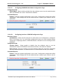
2.6.1
Quick Start up Software Version Information ................................................. 32
2.6.2
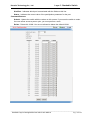
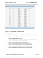
Quick Start up Physical Port Data ................................................................. 32
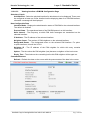
2.6.3
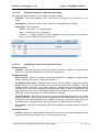
Quick Start up User Account Management .................................................... 33
2.6.4
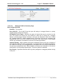
Quick Start up IP Address .............................................................................. 33
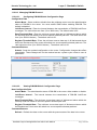
2.6.5
Quick Start up Uploading from Switch to Out-of-Band PC (Only XMODEM) 35
2.6.6
Quick Start up Downloading from Out-of-Band PC to Switch (Only XMODEM)
35
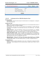
2.6.7
Quick Start up Downloading from TFTP Server............................................. 36
2.6.8
Quick Start up Factory Defaults ..................................................................... 36
2.6.9
Connecting Devices to the Switch ................................................................. 36
Console and Telnet Administration Interface ............................................................. 38
3.1
Local Console Management ............................................................................... 38
3.2
Set Up your Switch Using Console Access ........................................................ 38
3.3
Set Up your Switch Using Telnet Access ............................................................ 39
4
Web-Based Management Interface ........................................................................... 40
4.1
Overview ............................................................................................................ 40
4.2
How to log in ....................................................................................................... 40
_____________________________________________________________________________
Stackable Layer 3 Managed Ethernet Switch User Manual
Page: 3/661
Korenix Technology Co., Ltd.
4.3
5
Layer 3 Stackable Switch
Web-Based Management Menu ......................................................................... 41
Command Line Interface Structure and Mode-based CLI ......................................... 47
5.1
CLI Command Format ........................................................................................ 47
5.2
CLI Mode-based Topology.................................................................................. 47
6
Switching Commands ................................................................................................ 50
6.1
6.2
System Information and Statistics commands .................................................... 50
6.1.1
show arp ........................................................................................................ 50
6.1.2
show calendar ............................................................................................... 50
6.1.3
show eventlog................................................................................................ 51
6.1.4
show running-config ...................................................................................... 51
6.1.5
show sysinfo .................................................................................................. 52
6.1.6
show hardware .............................................................................................. 53
6.1.7
show loginsession ......................................................................................... 54
Device Configuration Commands ....................................................................... 54
6.2.1
Interface......................................................................................................... 55
6.2.1.1
show interface status ......................................................................... 55
6.2.1.2
show interface counters ..................................................................... 55
6.2.1.3
show interface switch......................................................................... 61
6.2.1.4
interface ............................................................................................. 62
6.2.1.5
speed-duplex ..................................................................................... 62
6.2.1.6
negotiate ............................................................................................ 63
6.2.1.7
capabilities ......................................................................................... 64
6.2.1.8
storm-control flowcontrol.................................................................... 65
6.2.1.9
shutdown ........................................................................................... 66
6.2.2
L2 MAC Address and Multicast Forwarding Database Tables ....................... 67
6.2.2.1
show mac-addr-table ......................................................................... 67
6.2.2.2
show mac-address-table gmrp .......................................................... 68
6.2.2.3
show mac-address-table igmpsnooping ............................................ 69
6.2.2.4
show mac-address-table multicast .................................................... 70
6.2.2.5
show mac-address-table stats ........................................................... 71
6.2.2.6
show mac-address-table agetime ...................................................... 71
6.2.2.7
mac-address-table aging-time ........................................................... 72
6.2.3
VLAN Management ....................................................................................... 72
6.2.3.1
show vlan ........................................................................................... 72
6.2.3.2
show vlan id ....................................................................................... 73
6.2.3.3
show protocol group .......................................................................... 74
6.2.3.4
show interface switchport .................................................................. 74
_____________________________________________________________________________
Stackable Layer 3 Managed Ethernet Switch User Manual
Page: 4/661
Korenix Technology Co., Ltd.
Layer 3 Stackable Switch
6.2.3.5
vlan database .................................................................................... 75
6.2.3.6
vlan .................................................................................................... 76
6.2.3.7
vlan name .......................................................................................... 76
6.2.3.8
vlan makestatic .................................................................................. 77
6.2.3.9
protocol group .................................................................................... 77
6.2.3.10
switchport acceptable-frame-type ...................................................... 78
6.2.3.11
switchport ingress-filtering ................................................................. 79
6.2.3.12
switchport native vlan ........................................................................ 80
6.2.3.13
switchport allowed vlan ...................................................................... 81
6.2.3.14
switchport tagging .............................................................................. 82
6.2.3.15
switchport priority ............................................................................... 83
6.2.3.16
switchport protocol group................................................................... 84
6.2.3.17
switchport forbidden vlan ................................................................... 87
6.2.4
GVRP and Bridge Extension ......................................................................... 87
6.2.4.1
show bridge-ext ................................................................................. 87
6.2.4.2
show gvrp configuration ..................................................................... 88
6.2.4.3
show gmrp configuration.................................................................... 89
6.2.4.4
show garp configuration..................................................................... 90
6.2.4.5
bridge-ext gvrp ................................................................................... 90
6.2.4.6
bridge-ext gmrp.................................................................................. 91
6.2.4.7
switchport gvrp................................................................................... 91
6.2.4.8
switchport gmrp ................................................................................. 92
6.2.4.9
garp timer........................................................................................... 94
6.2.5
IGMP Snooping ............................................................................................. 97
6.2.5.1
Show Commands .............................................................................. 97
6.2.5.2
Configuration Commands ................................................................ 100
6.2.6
Port Channel................................................................................................ 109
6.2.6.1
show port-channel ........................................................................... 109
6.2.6.2
port-channel ..................................................................................... 111
6.2.6.3
port-channel adminmode all ............................................................ 111
6.2.6.4
port-channel staticcapability ............................................................ 112
6.2.6.5
port-channel linktrap ........................................................................ 112
6.2.6.6
port-channel name ........................................................................... 113
6.2.6.7
adminmode ...................................................................................... 113
6.2.6.8
lacp .................................................................................................. 114
6.2.6.9
channel-group .................................................................................. 115
6.2.6.10
delete-channel-group ....................................................................... 115
_____________________________________________________________________________
Stackable Layer 3 Managed Ethernet Switch User Manual
Page: 5/661
Korenix Technology Co., Ltd.
6.2.7
Storm Control............................................................................................... 116
6.2.7.1
show storm-control .......................................................................... 116
6.2.7.2
storm-control broadcast ................................................................... 118
6.2.7.3
storm-control multicast..................................................................... 119
6.2.7.4
storm-control unicast ....................................................................... 120
6.2.7.5
switchport broadcast packet-rate ..................................................... 121
6.2.7.6
switchport multicast packet-rate ...................................................... 122
6.2.7.7
switchport unicast packet-rate ......................................................... 123
6.2.8
L2 Priority .................................................................................................... 124
6.2.8.1
show queue cos-map....................................................................... 124
6.2.8.2
queue cos-map ................................................................................ 125
6.2.9
6.3
Layer 3 Stackable Switch
Port Mirror.................................................................................................... 125
6.2.9.1
show port-monitor session ............................................................... 125
6.2.9.2
port-monitor session ........................................................................ 126
6.2.9.3
port-monitor session mode .............................................................. 127
Management Commands ................................................................................. 127
6.3.1
Network Commands .................................................................................... 127
6.3.1.1
show ip interface .............................................................................. 127
6.3.1.2
show ip filter ..................................................................................... 128
6.3.1.3
show ip ipv6 ..................................................................................... 129
6.3.1.4
mtu ................................................................................................... 129
6.3.1.5
interface vlan ................................................................................... 130
6.3.1.6
ip address ........................................................................................ 130
6.3.1.7
ip default-gateway............................................................................ 131
6.3.1.8
ip address protocol .......................................................................... 131
6.3.1.9
ip filter .............................................................................................. 132
6.3.1.10
ip ipv6 .............................................................................................. 133
6.3.2
Serial Interface Commands ......................................................................... 134
6.3.2.1
show line console ............................................................................ 134
6.3.2.2
line console ...................................................................................... 135
6.3.2.3
baudrate........................................................................................... 135
6.3.2.4
exec-timeout .................................................................................... 135
6.3.2.5
password-threshold ......................................................................... 136
6.3.2.6
silent-time ........................................................................................ 136
6.3.3
Telnet Session Commands .......................................................................... 137
6.3.3.1
telnet ................................................................................................ 137
6.3.3.2
show line vty .................................................................................... 138
_____________________________________________________________________________
Stackable Layer 3 Managed Ethernet Switch User Manual
Page: 6/661
Korenix Technology Co., Ltd.
Layer 3 Stackable Switch
6.3.3.3
line vty.............................................................................................. 138
6.3.3.4
exec-timeout .................................................................................... 139
6.3.3.5
password-threshold ......................................................................... 139
6.3.3.6
maxsessions .................................................................................... 140
6.3.3.7
sessions ........................................................................................... 140
6.3.3.8
telnet sessions ................................................................................. 141
6.3.3.9
telnet maxsessions .......................................................................... 141
6.3.3.10
telnet exec-timeout .......................................................................... 142
6.3.3.11
show telnet....................................................................................... 143
6.3.4
SNMP Server Commands ........................................................................... 143
6.3.4.1
show snmp....................................................................................... 143
6.3.4.2
show trapflags.................................................................................. 144
6.3.4.3
snmp-server sysname ..................................................................... 145
6.3.4.4
snmp-server location ....................................................................... 145
6.3.4.5
snmp-server contact ........................................................................ 146
6.3.4.6
snmp-server community .................................................................. 146
6.3.4.7
snmp-server host ............................................................................. 149
6.3.4.8
snmp-server enable traps ................................................................ 150
6.3.5
SNMP Trap Commands ............................................................................... 153
6.3.5.1
show snmptrap ................................................................................ 153
6.3.5.2
snmp trap link-status ........................................................................ 153
6.3.5.3
snmptrap <name> <ipaddr> ............................................................ 155
6.3.5.4
snmptrap ipaddr ............................................................................... 155
6.3.5.5
snmptrap mode ................................................................................ 156
6.3.6
HTTP commands......................................................................................... 156
6.3.6.1
show ip http...................................................................................... 156
6.3.6.2
ip javamode ..................................................................................... 157
6.3.6.3
ip http port ........................................................................................ 157
6.3.6.4
ip http server .................................................................................... 158
6.3.6.5
ip http secure-port ............................................................................ 159
6.3.6.6
ip http secure-server ........................................................................ 159
6.3.6.7
ip http secure-protocol ..................................................................... 159
6.3.7
Secure Shell (SSH) Commands .................................................................. 160
6.3.7.1
show ip ssh ...................................................................................... 160
6.3.7.2
ip ssh ............................................................................................... 161
6.3.7.3
ip ssh protocol.................................................................................. 161
6.3.7.4
ip ssh maxsessions.......................................................................... 162
_____________________________________________________________________________
Stackable Layer 3 Managed Ethernet Switch User Manual
Page: 7/661
Korenix Technology Co., Ltd.
6.3.7.5
6.3.8
DHCP Client Commands ............................................................................. 163
ip dhcp restart .................................................................................. 163
6.3.8.2
ip dhcp client-identifier ..................................................................... 163
DHCP Relay Commands ............................................................................. 164
6.3.9.1
Show bootpdhcprelay ...................................................................... 164
6.3.9.2
Bootpdhcprelay maxhopcount ......................................................... 165
6.3.9.3
Bootpdhcprelay serverip .................................................................. 165
Spanning Tree Commands ............................................................................... 166
6.4.1
Show Commands ........................................................................................ 166
6.4.1.1
show spanning-tree ......................................................................... 166
6.4.1.2
show spanning-tree interface ........................................................... 167
6.4.1.3
show spanning-tree vlan .................................................................. 168
6.4.1.4
show spanning-tree mst ................................................................... 169
6.4.1.5
show spanning-tree summary .......................................................... 172
6.4.1.6
show spanning-tree brief ................................................................. 173
6.4.2
6.5
ip ssh timeout................................................................................... 162
6.3.8.1
6.3.9
6.4
Layer 3 Stackable Switch
Configuration Commands ............................................................................ 173
6.4.2.1
spanning-tree ................................................................................... 173
6.4.2.2
spanning-tree protocol-migration ..................................................... 174
6.4.2.3
spanning-tree configuration ............................................................. 174
6.4.2.4
spanning-tree mode ......................................................................... 175
6.4.2.5
spanning-tree forward-time .............................................................. 176
6.4.2.6
spanning-tree hello-time .................................................................. 177
6.4.2.7
spanning-tree max-age .................................................................... 177
6.4.2.8
spanning-tree max-hops .................................................................. 178
6.4.2.9
spanning-tree mst ............................................................................ 178
6.4.2.10
spanning-tree port mode .................................................................. 182
6.4.2.11
spanning-tree edgeport.................................................................... 183
System Log Management Commands ............................................................. 183
6.5.1
Show Commands ........................................................................................ 183
6.5.1.1
show logging .................................................................................... 184
6.5.2
show logging buffered ................................................................................. 184
6.5.3
show logging traplog.................................................................................... 185
6.5.3.1
6.5.4
show logging hosts .......................................................................... 185
Configuration Commands ............................................................................ 186
6.5.4.1
logging buffered ............................................................................... 186
6.5.4.2
logging console ................................................................................ 187
_____________________________________________________________________________
Stackable Layer 3 Managed Ethernet Switch User Manual
Page: 8/661
Korenix Technology Co., Ltd.
6.6
6.7
6.5.4.3
logging host ..................................................................................... 188
6.5.4.4
logging syslog .................................................................................. 189
6.5.4.5
clear logging buffered ...................................................................... 190
Script Management Commands ....................................................................... 190
6.6.1
script apply .................................................................................................. 190
6.6.2
script delete ................................................................................................. 191
6.6.3
script list....................................................................................................... 191
6.6.4
script show................................................................................................... 192
User Account Management Commands ........................................................... 192
6.7.1
Show Commands ........................................................................................ 193
6.7.1.1
6.7.2
6.8
Layer 3 Stackable Switch
show users....................................................................................... 193
Configuration Commands ............................................................................ 193
6.7.2.1
username ......................................................................................... 193
6.7.2.2
username snmpv3 authentication .................................................... 194
6.7.2.3
username snmpv3 encryption.......................................................... 195
Security Commands ......................................................................................... 196
6.8.1
Show Commands ........................................................................................ 196
6.8.1.1
show users authentication ............................................................... 196
6.8.1.2
show authentication ......................................................................... 196
6.8.1.3
show authentication users ............................................................... 197
6.8.1.4
show dot1x....................................................................................... 197
6.8.1.5
show dot1x detail ............................................................................. 198
6.8.1.6
show dot1x statistics ........................................................................ 199
6.8.1.7
show dot1x summary ....................................................................... 200
6.8.1.8
show dot1x users ............................................................................. 201
6.8.1.9
show radius-servers......................................................................... 201
6.8.1.10
show radius...................................................................................... 202
6.8.1.11
show radius accounting ................................................................... 202
6.8.1.12
show radius statistics ....................................................................... 203
6.8.1.13
show tacacs ..................................................................................... 204
6.8.1.14
show port-security............................................................................ 205
6.8.2
Configuration Commands ............................................................................ 208
6.8.2.1
authentication login .......................................................................... 208
6.8.2.2
username defaultlogin ..................................................................... 209
6.8.2.3
username login ................................................................................ 209
6.8.3
Dot1x Configuration Commands ................................................................. 210
6.8.3.1
dot1x initialize .................................................................................. 210
_____________________________________________________________________________
Stackable Layer 3 Managed Ethernet Switch User Manual
Page: 9/661
Korenix Technology Co., Ltd.
6.8.3.2
dot1x default-login ........................................................................... 210
6.8.3.3
dot1x login ....................................................................................... 211
6.8.3.4
dot1x system-auth-control ............................................................... 211
6.8.3.5
dot1x user ........................................................................................ 212
6.8.3.6
dot1x port-control ............................................................................. 212
6.8.3.7
dot1x max-req .................................................................................. 214
6.8.3.8
dot1x re-authentication .................................................................... 214
6.8.3.9
dot1x re-reauthenticate .................................................................... 215
6.8.3.10
dot1x timeout ................................................................................... 215
6.8.4
Radius Configuration Commands................................................................ 216
6.8.4.1
radius accounting mode................................................................... 216
6.8.4.2
radius-server host ............................................................................ 217
6.8.4.3
radius-sever key .............................................................................. 218
6.8.4.4
radius-server retransmit ................................................................... 218
6.8.4.5
radius-server timeout ....................................................................... 219
6.8.4.6
radius-server msgauth ..................................................................... 220
6.8.4.7
radius-server primary ....................................................................... 220
6.8.5
TACACS Configuration Commands ............................................................ 221
6.8.5.1
tacacs .............................................................................................. 221
6.8.5.2
tacacs mode .................................................................................... 221
6.8.5.3
tacacs server-ip ............................................................................... 222
6.8.5.4
tacacs port ....................................................................................... 222
6.8.5.5
tacacs key ........................................................................................ 223
6.8.5.6
tacacs retry ...................................................................................... 223
6.8.5.7
tacacs timeout.................................................................................. 224
6.8.6
6.9
Layer 3 Stackable Switch
Port Security Configuration Commands ...................................................... 224
6.8.6.1
port-security ..................................................................................... 224
6.8.6.2
port-security max-dynamic............................................................... 225
6.8.6.3
port-security max-static .................................................................... 225
6.8.6.4
port-security mac-address ............................................................... 226
6.8.6.5
port-security mac-address move ..................................................... 227
CDP (Cisco Discovery Protocol) Commands ................................................... 227
6.9.1
Show Commands ........................................................................................ 227
6.9.1.1
show cdp.......................................................................................... 227
6.9.1.2
show cdp neighbors ......................................................................... 228
6.9.1.3
show cdp traffic ................................................................................ 229
6.9.2
Configuration Commands ............................................................................ 229
_____________________________________________________________________________
Stackable Layer 3 Managed Ethernet Switch User Manual
Page: 10/661
Korenix Technology Co., Ltd.
6.10
Layer 3 Stackable Switch
6.9.2.1
cdp ................................................................................................... 229
6.9.2.2
cdp run ............................................................................................. 230
6.9.2.3
cdp timer .......................................................................................... 230
6.9.2.4
cdp holdtime .................................................................................... 231
SNTP (Simple Network Time Protocol) Commands ......................................... 231
6.10.1 Show Commands ........................................................................................ 232
6.10.1.1
show sntp......................................................................................... 232
6.10.2 Configuration Commands ............................................................................ 233
6.11
6.10.2.1
sntp broadcast client poll-interval .................................................... 233
6.10.2.2
sntp client mode............................................................................... 234
6.10.2.3
sntp client port ................................................................................. 235
6.10.2.4
sntp unicast client poll-interval ......................................................... 235
6.10.2.5
sntp unicast client poll-timeout......................................................... 236
6.10.2.6
sntp unicast client poll-retry ............................................................. 236
6.10.2.7
sntp server ....................................................................................... 237
6.10.2.8
sntp clock timezone ......................................................................... 237
System Utilities ................................................................................................. 238
6.11.1 clear ............................................................................................................. 238
6.11.1.1
clear arp ........................................................................................... 238
6.11.1.2
clear traplog ..................................................................................... 239
6.11.1.3
clear eventlog .................................................................................. 239
6.11.1.4
clear logging buffered ...................................................................... 239
6.11.1.5
clear config ...................................................................................... 240
6.11.1.6
clear pass ........................................................................................ 240
6.11.1.7
clear counters .................................................................................. 241
6.11.1.8
clear dns counter ............................................................................. 241
6.11.1.9
clear dns cache................................................................................ 242
6.11.1.10 clear cdp .......................................................................................... 242
6.11.1.11 clear vlan ......................................................................................... 242
6.11.1.12 enable passwd ................................................................................. 243
6.11.1.13 clear igmp snooping......................................................................... 243
6.11.1.14 clear port-channel ............................................................................ 244
6.11.1.15 clear ip filter ..................................................................................... 244
6.11.1.16 clear dot1x statistics ........................................................................ 244
6.11.1.17 clear radius statistics ....................................................................... 245
6.11.1.18 clear tacacs...................................................................................... 245
6.11.2 copy ............................................................................................................. 246
_____________________________________________________________________________
Stackable Layer 3 Managed Ethernet Switch User Manual
Page: 11/661
Korenix Technology Co., Ltd.
Layer 3 Stackable Switch
6.11.3 delete ........................................................................................................... 248
6.11.4 dir................................................................................................................. 249
6.11.5 whichboot .................................................................................................... 249
6.11.6 boot-system ................................................................................................. 250
6.11.7 ping .............................................................................................................. 250
6.11.8 traceroute .................................................................................................... 251
6.11.9 logging cli-command.................................................................................... 252
6.11.10 calendar set ................................................................................................. 252
6.11.11 reload........................................................................................................... 253
6.11.12 configure ...................................................................................................... 253
6.11.13 disconnect ................................................................................................... 254
6.11.14 hostname ..................................................................................................... 254
6.11.15 quit ............................................................................................................... 255
6.12
Differentiated Service Command...................................................................... 255
6.12.1 General Commands .................................................................................... 256
6.12.1.1
diffserv ............................................................................................. 256
6.12.1.2
no diffserv ........................................................................................ 257
6.12.2 Class Commands ........................................................................................ 257
6.12.2.1
class-map ........................................................................................ 258
6.12.2.2
no class-map ................................................................................... 258
6.12.2.3
class-map rename ........................................................................... 259
6.12.2.4
match any ........................................................................................ 259
6.12.2.5
match class-map.............................................................................. 260
6.12.2.6
no match class-map......................................................................... 260
6.12.2.7
match dstip ...................................................................................... 261
6.12.2.8
match dstl4port ................................................................................ 261
6.12.2.9
match ip dscp................................................................................... 262
6.12.2.10 match ip precedence ....................................................................... 262
6.12.2.11 match ip tos ..................................................................................... 263
6.12.2.12 match protocol ................................................................................. 264
6.12.2.13 match srcip ...................................................................................... 264
6.12.2.14 match srcl4port ................................................................................ 265
6.12.3 Policy Commands........................................................................................ 265
6.12.3.1
assign-queue ................................................................................... 266
6.12.3.2
drop.................................................................................................. 266
6.12.3.3
redirect ............................................................................................. 267
6.12.3.4
conform-color ................................................................................... 267
_____________________________________________________________________________
Stackable Layer 3 Managed Ethernet Switch User Manual
Page: 12/661
Korenix Technology Co., Ltd.
Layer 3 Stackable Switch
6.12.3.5
mark cos .......................................................................................... 268
6.12.3.6
class................................................................................................. 268
6.12.3.7
no class............................................................................................ 269
6.12.3.8
mark ip-dscp .................................................................................... 269
6.12.3.9
mark ip-precedence ......................................................................... 269
6.12.3.10 police-simple .................................................................................... 270
6.12.3.11 policy-map ....................................................................................... 271
6.12.3.12 policy-map rename .......................................................................... 271
6.12.4 Service Commands ..................................................................................... 271
6.12.4.1
service-policy ................................................................................... 272
6.12.4.2
no service-policy .............................................................................. 273
6.12.5 Show Commands ........................................................................................ 273
6.13
6.12.5.1
show class-map ............................................................................... 273
6.12.5.2
show diffserv .................................................................................... 275
6.12.5.3
show policy-map .............................................................................. 275
6.12.5.4
show diffserv service ....................................................................... 277
6.12.5.5
show diffserv service brief ............................................................... 278
6.12.5.6
show policy-map interface ............................................................... 278
6.12.5.7
show service-policy.......................................................................... 280
ACL Command ................................................................................................. 280
6.13.1 Show Commands ........................................................................................ 280
6.13.1.1
show mac access-lists ..................................................................... 280
6.13.1.2
show mac access-lists ..................................................................... 281
6.13.1.3
show ip access-lists ......................................................................... 282
6.13.1.4
show access-lists interface .............................................................. 283
6.13.2 Configuration Commands ............................................................................ 283
6.14
6.13.2.1
mac access-list extended ................................................................ 283
6.13.2.2
mac access-list extended ................................................................ 284
6.13.2.3
mac access-list ................................................................................ 284
6.13.2.4
mac access-group in........................................................................ 285
6.13.2.5
access-list ........................................................................................ 286
6.13.2.6
no access-list ................................................................................... 287
6.13.2.7
ip access-group ............................................................................... 287
CoS (Class of Service) Command ................................................................... 288
6.14.1 Show Commands ........................................................................................ 288
6.14.1.1
show queue cos-map....................................................................... 288
6.14.1.2
show queue ip-precedence-mapping............................................... 288
_____________________________________________________________________________
Stackable Layer 3 Managed Ethernet Switch User Manual
Page: 13/661
Korenix Technology Co., Ltd.
Layer 3 Stackable Switch
6.14.1.3
show queue trust ............................................................................. 289
6.14.1.4
show queue cos-queue.................................................................... 290
6.14.2 Configuration Commands ............................................................................ 291
6.15
6.14.2.1
queue cos-map ................................................................................ 291
6.14.2.2
queue ip-precedence-mapping ........................................................ 292
6.14.2.3
queue trust ....................................................................................... 293
6.14.2.4
queue cos-queue min-bandwidth ..................................................... 294
6.14.2.5
queue cos-queue strict .................................................................... 295
6.14.2.6
queue cos-queue traffic-shape ........................................................ 296
LLDP (Link Layer Discovery Protocol) Commands .......................................... 298
6.15.1 Show Commands ........................................................................................ 298
7
6.15.1.1
show lldp .......................................................................................... 298
6.15.1.2
show lldp interface ........................................................................... 298
6.15.1.3
show lldp statistics ........................................................................... 299
6.15.1.4
show lldp remote-device .................................................................. 300
6.15.1.5
show lldp remote-device detail ........................................................ 300
6.15.1.6
show lldp local-device ...................................................................... 301
6.15.1.7
show lldp local-device detail ............................................................ 302
Routing Commands ................................................................................................. 303
7.1
Address Resolution Protocol (ARP) Commands .............................................. 303
7.1.1
7.1.1.1
show ip arp ...................................................................................... 303
7.1.1.2
show ip arp brief .............................................................................. 304
7.1.1.3
show ip arp static ............................................................................. 304
7.1.2
7.2
Show Commands ........................................................................................ 303
Configuration Commands ............................................................................ 305
7.1.2.1
arp.................................................................................................... 305
7.1.2.2
ip proxy-arp ...................................................................................... 305
7.1.2.3
arp cachesize................................................................................... 306
7.1.2.4
arp dynamicrenew ........................................................................... 306
7.1.2.5
arp purge ......................................................................................... 306
7.1.2.6
arp resptime ..................................................................................... 307
7.1.2.7
arp retries......................................................................................... 307
7.1.2.8
arp timeout ....................................................................................... 307
7.1.2.9
clear arp-cache ................................................................................ 308
IP Routing Commands ..................................................................................... 308
7.2.1
Show Commands ........................................................................................ 308
7.2.1.1
show ip brief..................................................................................... 308
_____________________________________________________________________________
Stackable Layer 3 Managed Ethernet Switch User Manual
Page: 14/661
Korenix Technology Co., Ltd.
7.2.1.2
show ip interface port....................................................................... 309
7.2.1.3
show ip interface brief ...................................................................... 310
7.2.1.4
show ip route ................................................................................... 310
7.2.1.5
show ip route bestroutes.................................................................. 311
7.2.1.6
show ip route entry .......................................................................... 311
7.2.1.7
show ip route precedence................................................................ 312
7.2.1.8
show ip traffic ................................................................................... 313
7.2.2
7.3
Layer 3 Stackable Switch
Configuration Commands ............................................................................ 313
7.2.2.1
routing .............................................................................................. 313
7.2.2.2
ip routing .......................................................................................... 314
7.2.2.3
ip address ........................................................................................ 314
7.2.2.4
ip route ............................................................................................. 314
7.2.2.5
ip route default-next-hop .................................................................. 315
7.2.2.6
ip route precedence ......................................................................... 315
7.2.2.7
ip forwarding .................................................................................... 316
7.2.2.8
ip directed-broadcast ....................................................................... 316
7.2.2.9
ip mtu ............................................................................................... 317
7.2.2.10
encapsulation................................................................................... 317
Open Shortest Path First (OSPF) Commands ................................................. 318
7.3.1
Show Commands ........................................................................................ 318
7.3.1.1
show ip ospf ..................................................................................... 318
7.3.1.2
show ip ospf area ............................................................................. 319
7.3.1.3
show ip ospf database ..................................................................... 320
7.3.1.4
show ip ospf interface ...................................................................... 320
7.3.1.5
show ip ospf interface brief .............................................................. 321
7.3.1.6
show ip ospf interface stats.............................................................. 322
7.3.1.7
show ip ospf neighbor ...................................................................... 322
7.3.1.8
show ip ospf neighbor brief .............................................................. 324
7.3.1.9
show ip ospf range ........................................................................... 324
7.3.1.10
show ip ospf stub table .................................................................... 325
7.3.1.11
show ip ospf virtual-link .................................................................... 326
7.3.1.12
show ip ospf virtual-link brief ............................................................ 326
7.3.2
Configuration Commands ............................................................................ 327
7.3.2.1
enable .............................................................................................. 327
7.3.2.2
no area............................................................................................. 328
7.3.2.3
ip ospf .............................................................................................. 328
7.3.2.4
1583compatibility ............................................................................. 328
_____________________________________________________________________________
Stackable Layer 3 Managed Ethernet Switch User Manual
Page: 15/661
Korenix Technology Co., Ltd.
7.4
Layer 3 Stackable Switch
7.3.2.5
area default-cost .............................................................................. 329
7.3.2.6
area nssa ......................................................................................... 329
7.3.2.7
area nssa default-info-originate ....................................................... 330
7.3.2.8
area nssa no-redistribute ................................................................. 330
7.3.2.9
area nssa no-summary .................................................................... 331
7.3.2.10
area nssa translator-role .................................................................. 331
7.3.2.11
area nssa translator-stab-intv .......................................................... 332
7.3.2.12
area range ....................................................................................... 332
7.3.2.13
area stub .......................................................................................... 333
7.3.2.14
area stub summarylsa ..................................................................... 333
7.3.2.15
area virtual-link authentication ......................................................... 334
7.3.2.16
area virtual-link dead-interval........................................................... 335
7.3.2.17
area virtual-link hello-interval ........................................................... 335
7.3.2.18
area virtual-link retransmit-interval................................................... 336
7.3.2.19
area virtual-link transmit-delay ......................................................... 336
7.3.2.20
default-information originate ............................................................ 337
7.3.2.21
default-metric ................................................................................... 337
7.3.2.22
distance ospf .................................................................................... 338
7.3.2.23
distribute-list out............................................................................... 339
7.3.2.24
exit-overflow-interval ........................................................................ 339
7.3.2.25
external-lsdb-limit............................................................................. 340
7.3.2.26
ip ospf areaid ................................................................................... 340
7.3.2.27
ip ospf authentication ....................................................................... 341
7.3.2.28
ip ospf cost....................................................................................... 342
7.3.2.29
ip ospf dead-interval ........................................................................ 342
7.3.2.30
ip ospf hello -interval ........................................................................ 343
7.3.2.31
ip ospf priority .................................................................................. 343
7.3.2.32
ip ospf retransmit-interval ................................................................ 344
7.3.2.33
ip ospf transmit-delay ....................................................................... 344
7.3.2.34
ip ospf mtu-ignore ............................................................................ 345
7.3.2.35
router-id ........................................................................................... 346
7.3.2.36
redistribute ....................................................................................... 346
7.3.2.37
maximum-paths ............................................................................... 347
Bootp/DHCP Relay Commands ....................................................................... 347
7.4.1
show bootpdhcprelay................................................................................... 347
7.4.2
bootpdhcprelay cidoptmode ........................................................................ 348
7.4.3
bootpdhcprelay enable ................................................................................ 348
_____________________________________________________________________________
Stackable Layer 3 Managed Ethernet Switch User Manual
Page: 16/661
Korenix Technology Co., Ltd.
7.5
7.4.4
bootpdhcprelay maxhopcount ..................................................................... 349
7.4.5
bootpdhcprelay minwaittime ........................................................................ 349
7.4.6
bootpdhcprelay serverip .............................................................................. 350
7.4.7
ip dhcp restart .............................................................................................. 350
7.4.8
ip dhcp client-identifier ................................................................................. 350
Domain Name Server Relay Commands ......................................................... 351
7.5.1
Show Commands ........................................................................................ 351
7.5.1.1
show hosts ....................................................................................... 351
7.5.1.2
show dns.......................................................................................... 351
7.5.1.3
show dns cache ............................................................................... 352
7.5.2
7.6
Layer 3 Stackable Switch
Configuration Commands ............................................................................ 353
7.5.2.1
ip hosts ............................................................................................ 353
7.5.2.2
clear hosts ....................................................................................... 353
7.5.2.3
ip domain-name ............................................................................... 354
7.5.2.4
ip domain-list.................................................................................... 354
7.5.2.5
ip name-server ................................................................................. 355
7.5.2.6
ip domain-lookup ............................................................................. 355
7.5.2.7
clear domain-list............................................................................... 356
7.5.2.8
clear dns .......................................................................................... 356
7.5.2.9
clear dns cache................................................................................ 357
7.5.2.10
clear dns counter ............................................................................. 357
Routing Information Protocol (RIP) Commands ............................................... 357
7.6.1
Show Commands ........................................................................................ 358
7.6.1.1
show ip rip........................................................................................ 358
7.6.1.2
show ip rip interface ......................................................................... 358
7.6.1.3
show ip rip interface brief ................................................................. 359
7.6.2
Configuration Commands ............................................................................ 360
7.6.2.1
enable rip ......................................................................................... 360
7.6.2.2
ip rip ................................................................................................. 360
7.6.2.3
auto-summary .................................................................................. 361
7.6.2.4
default-information originate ............................................................ 361
7.6.2.5
default-metric ................................................................................... 362
7.6.2.6
distance rip ...................................................................................... 362
7.6.2.7
hostrouteaccept ............................................................................... 363
7.6.2.8
split-horizon ..................................................................................... 363
7.6.2.9
distribute-list..................................................................................... 364
7.6.2.10
redistribute ....................................................................................... 365
_____________________________________________________________________________
Stackable Layer 3 Managed Ethernet Switch User Manual
Page: 17/661
Korenix Technology Co., Ltd.
7.7
7.8
7.9
7.6.2.11
ip rip authentication.......................................................................... 365
7.6.2.12
ip rip receive version ........................................................................ 366
7.6.2.13
ip rip send version............................................................................ 367
Router Discovery Protocol Commands ............................................................ 367
7.7.1
show ip irdp ................................................................................................. 367
7.7.2
ip irdp ........................................................................................................... 368
7.7.3
ip irdp broadcast .......................................................................................... 368
7.7.4
ip irdp holdtime ............................................................................................ 369
7.7.5
ip irdp maxadvertinterval ............................................................................. 369
7.7.6
ip irdp minadvertinterval .............................................................................. 370
7.7.7
ip irdp preference......................................................................................... 370
VLAN Routing Commands ............................................................................... 371
7.8.1
show ip vlan ................................................................................................. 371
7.8.2
vlan routing .................................................................................................. 371
Virtual Router Redundancy Protocol (VRRP) Commands ............................... 372
7.9.1
Show Commands ........................................................................................ 372
7.9.1.1
show ip vrrp ..................................................................................... 372
7.9.1.2
show ip vrrp brief ............................................................................. 372
7.9.1.3
show ip vrrp interface....................................................................... 373
7.9.1.4
show ip vrrp interface stats .............................................................. 374
7.9.2
8
Layer 3 Stackable Switch
Configuration Commands ............................................................................ 375
7.9.2.1
ip vrrp ............................................................................................... 375
7.9.2.2
ip vrrp ip ........................................................................................... 376
7.9.2.3
ip vrrp mode ..................................................................................... 376
7.9.2.4
ip vrrp authentication ....................................................................... 377
7.9.2.5
ip vrrp preempt................................................................................. 377
7.9.2.6
ip vrrp priority ................................................................................... 378
7.9.2.7
ip vrrp timers advertise .................................................................... 378
IP Multicast Commands ........................................................................................... 379
8.1
Distance Vector Multicast Routing Protocol (DVMRP) Commands .................. 379
8.1.1
Show Commands ........................................................................................ 379
8.1.1.1
show ip dvmrp.................................................................................. 379
8.1.1.2
show ip dvmrp interface ................................................................... 379
8.1.1.3
show ip dvmrp neighbor................................................................... 380
8.1.1.4
show ip dvmrp nexthop .................................................................... 381
8.1.1.5
show ip dvmrp prune ....................................................................... 381
8.1.1.6
show ip dvmrp route ........................................................................ 382
_____________________________________________________________________________
Stackable Layer 3 Managed Ethernet Switch User Manual
Page: 18/661
Korenix Technology Co., Ltd.
8.1.2
8.2
Configuration Commands ............................................................................ 382
8.1.2.1
ip dvmrp ........................................................................................... 382
8.1.2.2
ip dvmrp metric ................................................................................ 383
Internet Group Management Protocol (IGMP) Commands .............................. 383
8.2.1
Show Commands ........................................................................................ 383
8.2.1.1
show ip igmp .................................................................................... 383
8.2.1.2
show ip igmp groups ........................................................................ 384
8.2.1.3
show ip igmp interface ..................................................................... 385
8.2.1.4
show ip igmp interface membership ................................................ 386
8.2.1.5
show ip igmp interface stats ............................................................ 387
8.2.2
8.3
Layer 3 Stackable Switch
Configuration Commands ............................................................................ 387
8.2.2.1
ip igmp ............................................................................................. 387
8.2.2.2
ip igmp version................................................................................. 388
8.2.2.3
ip igmp last-member-query-count .................................................... 388
8.2.2.4
ip igmp last-member-query-interval ................................................. 389
8.2.2.5
ip igmp query-interval ...................................................................... 389
8.2.2.6
ip igmp query-max-response-time ................................................... 390
8.2.2.7
ip igmp robustness........................................................................... 390
8.2.2.8
ip igmp startup-query-count ............................................................. 391
8.2.2.9
ip igmp startup-query-interval .......................................................... 391
Multicast Commands ........................................................................................ 392
8.3.1
Show Commands ........................................................................................ 392
8.3.1.1
show ip mcast .................................................................................. 392
8.3.1.2
show ip mcast boundary .................................................................. 393
8.3.1.3
show ip mcast interface ................................................................... 393
8.3.1.4
show ip mcast mroute ...................................................................... 394
8.3.1.5
show mrinfo ..................................................................................... 397
8.3.1.6
show mstat ....................................................................................... 397
8.3.1.7
show mtrace .................................................................................... 398
8.3.2
Configuration Commands ............................................................................ 398
8.3.2.1
ip multicast ....................................................................................... 399
8.3.2.2
ip multicast staticroute ..................................................................... 399
8.3.2.3
no ip mcast mroute .......................................................................... 400
8.3.2.4
ip mcast boundary ........................................................................... 401
8.3.2.5
ip multicast ttl-threshold ................................................................... 401
8.3.2.6
mrinfo ............................................................................................... 402
8.3.2.7
mstat ................................................................................................ 402
_____________________________________________________________________________
Stackable Layer 3 Managed Ethernet Switch User Manual
Page: 19/661
Korenix Technology Co., Ltd.
8.4
8.3.2.8
mtrace .............................................................................................. 403
8.3.2.9
disable ip multicast mdebug mtrace ................................................ 404
Protocol Independent Multicast – Dense Mode (PIM-DM) Commands ............ 404
8.4.1
show ip pimdm ................................................................................. 404
8.4.1.2
show ip pimdm interface .................................................................. 405
8.4.1.3
show ip pimdm interface stats ......................................................... 406
8.4.1.4
show ip pimdm neighbor .................................................................. 406
Configuration Commands ............................................................................ 407
8.4.2.1
ip pimdm .......................................................................................... 407
8.4.2.2
ip pimdm mode ................................................................................ 407
8.4.2.3
ip pimdm query-interval ................................................................... 408
Protocol Independent Multicast – Sparse Mode (PIM-SM) Commands ........... 408
8.5.1
Show Commands ........................................................................................ 408
8.5.1.1
show ip pimsm ................................................................................. 408
8.5.1.2
show ip pimsm componenttable ...................................................... 409
8.5.1.3
show ip pimsm interface .................................................................. 410
8.5.1.4
show ip pimsm interface stats .......................................................... 410
8.5.1.5
show ip pimsm neighbor .................................................................. 411
8.5.1.6
show ip pimsm rp ............................................................................. 412
8.5.1.7
show ip pimsm rphash ..................................................................... 413
8.5.1.8
show ip pimsm staticrp .................................................................... 413
8.5.2
9
Show Commands ........................................................................................ 404
8.4.1.1
8.4.2
8.5
Layer 3 Stackable Switch
Configuration Commands ............................................................................ 414
8.5.2.1
ip pimsm .......................................................................................... 414
8.5.2.2
ip pimsm message-interval .............................................................. 414
8.5.2.3
ip pimsm register-rate-limit .............................................................. 415
8.5.2.4
ip pimsm spt-threshold..................................................................... 415
8.5.2.5
ip pimsm staticrp .............................................................................. 416
8.5.2.6
ip pimsm mode ................................................................................ 416
8.5.2.7
ip pimsm query-interval .................................................................... 417
8.5.2.8
ip pimsm cbsrpreference ................................................................. 417
8.5.2.9
ip pimsm cbsrhashmasklength ........................................................ 418
8.5.2.10
ip pimsm crppreference ................................................................... 418
Rapid Super Ring Member Mode Commands ......................................................... 420
9.1
Global Configuration ......................................................................................... 420
9.2
Rapid Super Ring Configuration ....................................................................... 420
9.3
Rapid Super Ring Summary ............................................................................. 421
_____________________________________________________________________________
Stackable Layer 3 Managed Ethernet Switch User Manual
Page: 20/661
Korenix Technology Co., Ltd.
10
Layer 3 Stackable Switch
Stacking Commands ................................................................................................ 422
10.1
show switch ...................................................................................................... 422
10.2
show supported switchtype .............................................................................. 423
10.3
switch provision ................................................................................................ 424
10.4
switch priority .................................................................................................... 424
10.5
switch renumber ............................................................................................... 425
10.6
switch movemanagement ................................................................................. 425
10.7
archive copy-sw ................................................................................................ 426
10.8
archive download-sw ........................................................................................ 427
10.9
reload ............................................................................................................... 427
10.10
session ............................................................................................................. 428
11
Web-Based Management Interface ......................................................................... 429
11.1
Overview .......................................................................................................... 429
11.2
Main Menu ........................................................................................................ 430
11.2.1 System Menu............................................................................................... 430
11.2.1.1
View ARP Cache ............................................................................. 430
11.2.1.2
Viewing Inventory Information ......................................................... 430
11.2.1.3
Configuring Management Session and Network Parameters .......... 432
11.2.1.4
Defining Forwarding Database ........................................................ 442
11.2.1.5
Viewing Logs ................................................................................... 444
11.2.1.6
Managing Switch Interface .............................................................. 449
11.2.1.7
Defining SNMP ................................................................................ 455
11.2.1.8
Viewing Statistics ............................................................................. 458
11.2.1.9
Managing System Utilities ............................................................... 468
11.2.1.10 Defining Trap Manager .................................................................... 475
11.2.1.11 Configuring SNTP ............................................................................ 477
11.2.1.12 Defining DHCP Client ...................................................................... 484
11.2.2 Switching Menu ........................................................................................... 485
11.2.2.1
Managing Port-based VLAN ............................................................ 485
11.2.2.2
Managing Protocol-based VLAN ..................................................... 490
11.2.2.3
Defining GARP ................................................................................ 492
11.2.2.4
Managing IGMP Snooping ............................................................... 495
11.2.2.5
Managing Port-Channel ................................................................... 503
11.2.2.6
Viewing Multicast Forwarding Database .......................................... 506
11.2.2.7
Managing Spanning Tree ................................................................. 509
11.2.2.8
Defining 802.1p priority .................................................................... 517
11.2.2.9
Managing Port Security ................................................................... 518
_____________________________________________________________________________
Stackable Layer 3 Managed Ethernet Switch User Manual
Page: 21/661
Korenix Technology Co., Ltd.
Layer 3 Stackable Switch
11.2.2.10 Managing LLDP (Link Layer Discovery Protocol) ............................ 521
11.2.3 Routing Menu .............................................................................................. 527
11.2.3.1
Managing ARP Table ....................................................................... 527
11.2.3.2
Managing IP Interfaces .................................................................... 529
11.2.3.3
Managing OSPF .............................................................................. 535
11.2.3.4
Managing BOOTP/DHCP Relay Agent ............................................ 556
11.2.3.5
Managing DNS Relay ...................................................................... 558
11.2.3.6
Managing Routing Information Protocol (RIP) ................................. 562
11.2.3.7
Managing Router Discovery ............................................................ 569
11.2.3.8
Managing Route Table ..................................................................... 571
11.2.3.9
Managing VLAN Routing ................................................................. 576
11.2.3.10 Managing VRRP .............................................................................. 578
11.2.4 Security Menu.............................................................................................. 583
11.2.4.1
Managing Access Control (802.1x) .................................................. 583
11.2.4.2
Managing RADIUS .......................................................................... 592
11.2.4.3
Defining TACACS Configuration ...................................................... 598
11.2.4.4
Defining IP Filter Configuration ........................................................ 599
11.2.4.5
Defining Secure Http Configuration ................................................. 600
11.2.4.6
Defining Secure Shell Configuration ................................................ 601
11.2.5 QOS Menu................................................................................................... 602
11.2.5.1
Managing Access Control Lists ........................................................ 602
11.2.5.2
Managing Differentiated Services .................................................... 611
11.2.5.3
Configuring Diffserv Wizard Page .................................................... 618
11.2.5.4
Managing Class of Service .............................................................. 619
11.2.6 IP Multicast Menu ........................................................................................ 624
11.2.6.1
Managing DVMRP Protocol ............................................................. 624
11.2.6.2
Managing IGMP Protocol ................................................................. 629
11.2.6.3
Defining Multicast Configuration ...................................................... 635
11.2.6.4
Configuring Multicast Mdebug ......................................................... 640
11.2.6.5
Managing PIM-DM Protocol............................................................. 644
11.2.6.6
Managing PIM-SM Protocol ............................................................. 647
11.2.7 Rapid Super Ring Menu .............................................................................. 652
11.2.7.1
Global Configuration ........................................................................ 652
11.2.7.2
Rapid Super Ring Configuration ...................................................... 653
11.2.7.3
Rapid Super Ring Summary ............................................................ 653
11.2.8 Stacking Menu ............................................................................................. 654
11.2.8.1
Configuring Stack Unit ..................................................................... 654
_____________________________________________________________________________
Stackable Layer 3 Managed Ethernet Switch User Manual
Page: 22/661
Korenix Technology Co., Ltd.
Layer 3 Stackable Switch
11.2.8.2
Downloading Runtime Image to Stack Members ............................. 656
11.2.8.3
Viewing Stack Summary Information ............................................... 657
11.2.8.4
Viewing Stack Port Summary Information........................................ 657
11.2.8.5
Viewing Stack Port Counters Information ........................................ 658
11.2.8.6
Viewing Stack Port Counters Detail Information .............................. 659
_____________________________________________________________________________
Stackable Layer 3 Managed Ethernet Switch User Manual
Page: 23/661
Korenix Technology Co., Ltd.
Layer 3 Stackable Switch
1 Introduction
1.1 Switch Description
The JetNet 6524G is a 19-inch Gigabit Stackable Layer 3 Managed Switch, equipped with 24
10/100/1000 Base-TX ports and 4 Gigabit SFP combo ports delivering maximum throughput
and flexibility for high-density and ultra high-speed connection. With stacking cable installation,
up to 8 units can be stacked together, allowing building a single-IP manageable device and
simultaneously providing 40G backplane across full duplex stacking links. The flexible interface
design allows JetNet 6524G to provide up to 192 Gigabit ports per stack and 384G bandwidth
for building intelligent largescale networks.
In addition to the 90-264VAC power-based JetNet 6524G model, Korenix provides the JetNet
6524GDC series, which support 24V or 48V power inputs and feature a FAN-less design with
-40~65℃oC wide operating temperature for severe industrial applications..
1.2 Features
•
Supports 24 10/100/1000BASE-T RJ45 Ethernet ports
•
4 built-in combination 1000BASE-T/SFP ports
•
2 10G backplane for stacking up to 8 units with 192 ports and 384G bandwidth
•
Supports IP, VLAN & Multicast routing
•
IP Routing protocol supports RIP v1 / v2, OSPF v1/v2
•
Supports L3 Multicast, PIM-DM and PIM-SM, DVMRP, IGMP v1/v2/v3
•
Virtual Redundant Router Protocol (VRRP) for gateway redundancy
•
Supports LLDP and JetView Pro i2NMS for network auto topology visualization and
efficient group management
•
Multiple Super Ring member mode
•
802.1s Multiple Spanning Tree Protocol and 802.1w RSTP for network redundancy
•
Supports 512 VLANs, GVRP/GMRP, protocol VLAN
•
802.3ad LACP, up to 6 trunk groups, unicast and multicast load balance
•
Supports L2 / L3 / L4 ACL (access control list)
•
IEEE 802.1x Port-Based Authentication, RADIUS and TACACS client, SSH, SSL, TLS,
Port binding
•
FAN-less design with -40~65℃ wide operating temperature (JetNet 6524G-DC)
_____________________________________________________________________________
Stackable Layer 3 Managed Ethernet Switch User Manual
Page: 24/661
Korenix Technology Co., Ltd.
Layer 3 Stackable Switch
1.3 Front-Panel Components
The front panel of the Switch consists of LED indicators, Gigabit Ethernet ports and four
SFP (Mini-GBIC) Combo ports.
Figure 1-1. Front Panel View of the switch
Comprehensive LED indicators display the status of the startup Self test/Power, Status (of
the stacking master) and the port Link/Activity.
1.4 LED Indicators
The LED indicators of the front panel include Power, Console, and Ethernet Port
Link/Act.status. A bank of 24 LEDs (2 for each port) indicates link, activity status, and
connection speed for each port.
In the Real panel, the LEDs indicate the Stacking status. A band of 8 ports (4 for each
stacking port) indicates Status, RX, TX, Link of the 2 stacking ports.
1.5 Rear Panel Description
The rear panel of the Switch contains an AC power connector or DC power connector, a
RS-232 console port, the connector for the two stacking ports. An RS-232 DCE console port is
for setting up and managing the Switch via a connection to a console terminal or PC using a
terminal emulation program. The default baud rate is 115,200, N, 8, 1.
Figure 1-2. Rear panel view of the switch, JetNet 6524G
The AC power connector is a standard three-pronged connector that supports the power
cord. Plug the female connector of the provided power cord into this socket, and the male side
of the cord into a power outlet. The Switch automatically adjusts its power setting to any supply
voltage in the range from 100 ~ 240 VAC at 50 ~ 60 Hz.
The stacking connector is a standard CX4 type with 10G full duplex transmission
capability. There are Status, TX, RX and Link LED to indicate the status. See detail description
at Ch2.4.
DC Power Input apply to the JetNet 6524G-DC
_____________________________________________________________________________
Stackable Layer 3 Managed Ethernet Switch User Manual
Page: 25/661
Korenix Technology Co., Ltd.
Layer 3 Stackable Switch
Follow below steps to wire JetNet 6524G-DC redundant DC power inputs. The power
range support 24V(18-36VDC) or 48V(36-72V) DC input. Choose the power input model
you prefered.
1.
Insert positive and negative wires into V+ and Vcontacts respectively of the terminal block connector
2.
Tighten the wire-clamp screws to prevent DC wires
from being loosened.
3.
Power 1 and Power 2 support power redundancy and
polarity reverse protection functions.
4.
Positive and negative power system inputs are both
accepted, but Power 1 and Power 2 must apply the
same mode.
Note 1: It is a good practice to turn off input and load power, and to unplug power terminal
block before making wire connections. Otherwise, your screwdriver blade can inadvertently
short your terminal connections to the grounded enclosure.
Note 2: The range of the suitable DC electric wire is from 12 to 24 AWG.
1.6 Management Options
The system may be managed out-of-band through the console port on the rear panel or
in-band using Telnet, a Web Browser, or SNMP.
1.7 Web-based Management Interface
After you have successfully installed the Switch, you can configure the Switch, monitor the
LED panel, and display statistics graphically using a Web browser, such as Netscape
Navigator (version 6.2 and higher) or Microsoft® Internet Explorer (version 5.0).
The default IP address before configuring is 192.168.2.1. User Name is admin, no
default password is requested.
After configured the layer 3 vitual interfaces, you can assign primary IP and second IP
addresses to the interface, this is known as default gateway of the lower hosts. The lower hosts
in each subnet can access the interface by the default gateway IP address.
The default IP address is only available in layer 2 mode, the layer 2 mode means there is
no any configured layer 3 virtual interface. After configured the layer 3 vitual interface, the
default IP address is changed to the assigned primary/second IP address of the interface.
NOTE: To access the Switch through a Web browser, the computer running the Web browser
must have IP-based network access to the Switch. It is not suggested multiple user’s access to
the web browser. The performance of web display would be affected.
_____________________________________________________________________________
Stackable Layer 3 Managed Ethernet Switch User Manual
Page: 26/661
Korenix Technology Co., Ltd.
Layer 3 Stackable Switch
Warning: Since the lower hosts under the layer 3 interface can access the switch by
default gateway IP address. Please remember to change the user name and password
in your first login. Otherwise, the users can easily access the management interface and
change the settings. It obeys the common security concern.
1.8 Command Line Console Interface Through the Serial Port or Telnet
You can also connect a computer or terminal to the serial console port or use Telnet to
access the Switch. The command-line-driven interface provides complete access to all switch
management features.
1.9 SNMP-Based Management
You can manage the Switch with an SNMP-compatible console program. The Switch
supports SNMP version 1.0, version 2.0, and version 3.0. The SNMP agent decodes the
incoming SNMP messages and responds to requests with MIB objects stored in the database.
The SNMP agent updates the MIB objects to generate statistics The Switch supports a
comprehensive set of MIB extensions:
• RFC1643 Ether-like MIB
• RFC1493 Bridge
• RFC 2819 RMON
• RFC2233 Interface MIB
• RFC2571 (SNMP Frameworks)
• RFC2572 (Message Processing for SNMP)
• RFC2573 (SNMP Applications)
• RFC2576 (Coexistence between SNMPs)
• RFC2618 (Radius-Auth-Client-MIB)
• RFC2620 (Radius-Acc-Client-MIB)
• RFC 1724 (RIPv2-MIB)
• RFC 1850 (OSPF-MIB)
• RFC 1850 (OSPF-TRAP-MIB)
• RFC 2787 (VRRP-MIB)
• RFC 3289 - DIFFSERV-DSCP-TC
• RFC 3289 - DIFFSERV-MIB
• QOS-DIFFSERV-EXTENSIONS-MIB
• QOS-DIFFSERV-PRIVATE-MIB
• RFC2674 802.1p
• RFC 2932 (IPMROUTE-MIB)
ROUTING-MIB
• MGMD-MIB
• RFC 2934 PIM-MIB
• DVMRP-STD-MIB
_____________________________________________________________________________
Stackable Layer 3 Managed Ethernet Switch User Manual
Page: 27/661
Korenix Technology Co., Ltd.
Layer 3 Stackable Switch
• IANA-RTPROTO-MIB
• MULTICAST-MIB
1.10 Model Name & Packaging
JetNet 6524G 24-Port Gigabit Stackable Layer 3 Managed Ethernet Switch
Includes:
JetNet 6524G (without SFP transceivers)
Rack Mount Kit
Document CD
AC Power Cord
JetNet 6524G-DC24 24-Port Gigabit Stackable Layer 3 Managed Ethernet Switch, 24VDC
Power input
Includes:
JetNet 6524G-DC24 (without SFP transceivers)
Rack Mount Kit
Document CD
JetNet 6524G-DC48 24-Port Gigabit Stackable Layer 3 Managed Ethernet Switch, 48VDC
Power input
Includes:
JetNet 6524G-DC48 (without SFP transceivers)
Rack Mount Kit
Document CD
JNSC-CX405M-S: JetNet CX4 Stacking Cable, Length : 0.5M, Screw Type
JNSC-CX410M-S: JetNet CX4 Stacking Cable, Length : 1.0M, Screw Type
_____________________________________________________________________________
Stackable Layer 3 Managed Ethernet Switch User Manual
Page: 28/661
Korenix Technology Co., Ltd.
Layer 3 Stackable Switch
2 Installation and Quick Startup
2.1 Package Contents
Before you begin installing the Switch, confirm that your package contains the following items:
• One JetNet 6524G Switch
• Mounting kit: 2 mounting brackets and screws
• One AC power cord
• Console Cable
• CD-ROM with User’s Guide and CLI Reference
2.2 Switch Installation
Installing the Switch Without the Rack
1. Install the Switch on a level surface that can safely support the weight of the Switch and its
attached cables. The Switch must have adequate space for ventilation and for accessing cable
connectors.
2. Set the Switch on a flat surface and check for proper ventilation. Allow at least 5 cm (2
inches) on each side of the Switch and 15 cm (6 inches) at the back for the power cable.
3. Attach the rubber feet on the marked locations on the bottom of the chassis.
The rubber feet are recommended to keep the unit from slipping.
2.3 Installing the Switch in a Rack
You can install the Switch in most standard 19-inch (48.3-cm) racks. Refer to the illustrations
below.
1. Use the supplied screws to attach a mounting bracket to each side of the Switch.
2. Align the holes in the mounting bracket with the holes in the rack.
3. Insert and tighten two screws through each of the mounting brackets.
Note 1: When installing multiple switches, mount them in the rack one below the other. It’s requested to
reserve 0.5U-1U free space for multiple switches installing. This is important to disperse the heat
generated by the switch.
Note 2: Temperature: Check if the rack environment temperature conforms to the specified operating
temperature range.
Note 3: Mechanical Loading: Do no place any equipment on top of the switch
_____________________________________________________________________________
Stackable Layer 3 Managed Ethernet Switch User Manual
Page: 29/661
Korenix Technology Co., Ltd.
Layer 3 Stackable Switch
2.4 Stacking the Switches
A total of 8 switches can be put into a single stack. Stacked JetNet 6524G Switches can be
assigned a single IP address using the switch's management software. The stack can then be
treated as a single manageable unit with one IP address.
1. Make sure all switches in the stack are powered off.
2. Connect switches through the HighGig ports in the backplane.
_____________________________________________________________________________
Stackable Layer 3 Managed Ethernet Switch User Manual
Page: 30/661
Korenix Technology Co., Ltd.
Layer 3 Stackable Switch
3. Power on the switches.
4. The Link LED in the rear panel indicates the link status of the stacking port.
Fig. 2-4: Cabling three JetNet 6524G switches.
Note: Korenix provide the stacking cable for purchasement. When the volume of the stack is
under 4, the JNSC-CX405M-S, 50cm stacking cable is enough. When the volume is above 4,
additional one JNSC=CX401M-S, 100cm stacking cable is required for the connection from the
unit 1 to the last unit.
2.5 Quick Starting the Switch
1. In-band connectivity allows access to the JetNet 6524G Switch locally or from a remote
workstation. The device must be configured with IP information (IP address, subnet mask, and
default gateway).
2. Turn the Power ON.
3. Allow the device to load the software until the login prompt appears. The device initial state
is called the default mode.
4. When the prompt asks for operator login, do the following:
• Type the word admin in the login area. Since a number of the Quick Setup commands
require administrator account rights, KORENIX suggests logging into an administrator
account.
• Do not enter a password because there is no password in the default mode.
• Press the <Enter> key
• The CLI Privileged EXEC mode prompt will be displayed.
• Use “configure” to switch to the Global Config mode from Privileged EXEC.
• Use “exit” to return to the previous mode.
2.6 System Information Setup
_____________________________________________________________________________
Stackable Layer 3 Managed Ethernet Switch User Manual
Page: 31/661
Korenix Technology Co., Ltd.
2.6.1
Layer 3 Stackable Switch
Quick Start up Software Version Information
Table 2-1. Quick Start up Software Version Information
Command
show hardware
Details
Allows the user to see the HW & SW
version the device contains
System Description - switch's model
name
show switch
2.6.2
Burned in MAC address - MAC address
assigned to this switch CPU
Quick Start up Physical Port Data
Table 2-2. Quick Start up Physical Port
Command
show Interface status
{ <unit/slot/port> | all}
Details
Displays the Ports
unit/slot/port
Type - Indicates if the port is a special
type of port
Admin Mode - Selects the Port Control
Administration State
Physical Mode - Selects the desired port
speed and duplex mode
Physical Status - Indicates the port speed
and duplex mode
Link Status - Indicates whether the link is
up or down
Link Trap - Determines whether or not to
send a trap when link status changes
LACP Mode - Displays whether LACP is
enabled or disabled on this port
Flow Mode - Indicates the status of flow
control on this port
Cap. Status - Indicates the
capabilities during auto-negotiation
port
_____________________________________________________________________________
Stackable Layer 3 Managed Ethernet Switch User Manual
Page: 32/661
Korenix Technology Co., Ltd.
2.6.3
Layer 3 Stackable Switch
Quick Start up User Account Management
Table 2-3. Quick Start up User Account Management
Command
show users
Details
Displays all users that are allowed to
access the switch
User Access Mode - Shows whether the
user is able to change parameters on the
switch (Read/Write) or is only able to view
(Read Only).
As a factory default, admin has
Read/Write access and guest has Read
Only access. There can only be one
Read/Write user and up to 5 Read Only
users.
show loginsession
Displays all login session information
username <username> {passwd | Allows the user to set passwords or
change passwords needed to login
nopasswd}
A prompt will appear after the command is
entered requesting the old password. In
the absence of an old password leave the
area blank. The operator must press enter
to execute the command.
The system then prompts the user for a
new password then a prompt to confirm
the new password. If the new password
and the confirmed password match a
message will be displayed.
The user password should not be more
than eight characters in length.
copy running-config
startup-config [filename]
This will save passwords and all other
changes to the device.
If you do not save config, all
configurations will be lost when a power
cycle is performed on the switch or when
the switch is reset.
2.6.4
Quick Start up IP Address
_____________________________________________________________________________
Stackable Layer 3 Managed Ethernet Switch User Manual
Page: 33/661
Korenix Technology Co., Ltd.
Layer 3 Stackable Switch
To view the network parameters the operator can access the device by the following three
methods.
• Simple Network Management Protocol - SNMP
• Telnet
• Web Browser
Table 2-4. Quick Start up IP Address
Command
show ip interface
Details
Displays the Network Configurations
IP Address - IP Address of the interface
Default IP is 192.168.2.1
Subnet Mask - IP Subnet Mask for the
interface
Default is 255.255.255.0
Default Gateway - The default Gateway
for this interface
Default value is 0.0.0.0
Burned in MAC Address - The Burned in
MAC
Address
used
for
inband
connectivity
Network Configurations Protocol Current Indicates which network protocol is being
used
Default is none
Management VLAN ID - Specifies VLAN
id without configured any layer 3 vitual
interface. After configured layer 3
interface, the management VLAN ID is
not available.
Web
Mode
Indicates
HTTP/Web is enabled.
whether
Java Mode - Indicates whether java
mode is enabled.
ip address
(Config)#interface vlan 1
(if-vlan 1)#ip address <ipaddr>
<netmask>
(if-vlan 1)#exit
(Config)#ip default-gateway <gateway>
IP Address range
255.255.255.255
from
0.0.0.0
to
Subnet Mask range from 0.0.0.0 to
255.255.255.255
_____________________________________________________________________________
Stackable Layer 3 Managed Ethernet Switch User Manual
Page: 34/661
Korenix Technology Co., Ltd.
Layer 3 Stackable Switch
Gateway Address range from 0.0.0.0 to
255.255.255.255
Displays all
information
2.6.5
of
the
login
session
Quick Start up Uploading from Switch to Out-of-Band PC (Only XMODEM)
Table 2-5. Quick Start up Uploading from Switch to Out-of-Band PC (XMODEM)
Command
Details
copy startup-config <filename>
This starts the upload and displays the
xmodem
mode of uploading and the type of upload
it is and confirms the upload is taking
place.
For example:
If the user is using HyperTerminal, the
user must specify where the file is going
to be received by the pc.
2.6.6
Quick Start up Downloading from Out-of-Band PC to Switch (Only XMODEM)
Table 2-6 Quick Start up Downloading from Out-of-Band PC to Switch
Command
copy xmodem startup-config
<filename>
Details
Sets the download datatype to be an
image or config file.
The URL must be specified as: xmodem:
filepath/ filename
For example:
If the user is using HyperTerminal, the
user must specify which file is to be sent
to the switch. The Switch will restart
automatically once the code has been
downloaded.
_____________________________________________________________________________
Stackable Layer 3 Managed Ethernet Switch User Manual
Page: 35/661
Korenix Technology Co., Ltd.
2.6.7
Layer 3 Stackable Switch
Quick Start up Downloading from TFTP Server
Before starting a TFTP server download, the operator must complete the Quick Start up
for the IPAddress.
Table 2-7 Quick Start up Downloading from TFTP Server
Command
copy <url> startup-config
<filename>
Details
Sets the download datatype to be an
image or config file.
The URL must be specified
tftp://ipAddr/filepath/fileName.
as:
The startup-config option downloads the
config file using tftp and image option
downloads the code file.
2.6.8
Quick Start up Factory Defaults
Table 2-8 Quick Start up Factory Defaults
Command
Details
clear config
Enter yes when the prompt pops up to
clear all the configurations made to the
switch.
copy running-config
Enter yes when the prompt pops up that
asks if you want to save the
configurations made to the switch.
startup-config [filename]
reload
Enter yes when the prompt pops up that
asks if you want to reset the system.
You can reset the switch or cold boot the
switch; both work effectively.
2.6.9
Connecting Devices to the Switch
_____________________________________________________________________________
Stackable Layer 3 Managed Ethernet Switch User Manual
Page: 36/661
Korenix Technology Co., Ltd.
Layer 3 Stackable Switch
After assigning IP addresses to the Switch, you can connect devices to the Switch.
To connect a device to an SFP transceiver port:
1. Use your cabling requirements to select an appropriate SFP transceiver type.
2. Insert the SFP transceiver (sold separately) into the SFP transceiver slot.
3. Use the appropriate network cabling to connect a device to the connectors on the SFP
transceiver.
_____________________________________________________________________________
Stackable Layer 3 Managed Ethernet Switch User Manual
Page: 37/661
Korenix Technology Co., Ltd.
Layer 3 Stackable Switch
3 Console and Telnet Administration Interface
This chapter discusses many of the features used to manage the Switch, and explains
many concepts and important points regarding these features. Configuring the Switch to
implement these concepts is discussed in detail in chapter 6.
3.1 Local Console Management
Local console management involves the administration of the Switch via a direct
connection to the RS-232 DCE console port. This is an Out-of-band connection, meaning that it
is on a different circuit than normal network communications, and thus works even when the
network is down.
The local console management connection involves a terminal or PC running terminal
emulation software to operate the Switch’s built-in console program (see Chapter 6). Using the
console program, a network administrator can manage, control, and monitor many functions of
the Switch. Hardware components in the Switch allow it to be an active part of a manageable
network. These components include a CPU, memory for data storage, other related hardware,
and SNMP agent firmware. Activities on the Switch can be monitored with these components,
while the Switch can be manipulated to carry out specific tasks.
3.2 Set Up your Switch Using Console Access
Out-of-band management requires connecting a terminal, such as a VT-100 or a PC
running a terminal-emulation program (such as HyperTerminal, which is automatically installed
with Microsoft Windows) to the RS-232 DCE console port of the Switch. Switch management
using the RS-232 DCE console port is called Local Console Management to differentiate it
from management done via management platforms, such as DView or HP OpenView.
Make sure the terminal or PC you are using to make this connection is configured to
match these settings. If you are having problems making this connection on a PC, make sure
the emulation is set to VT-100 or ANSI. If you still don’t see anything, try pressing <Ctrl> + r to
refresh the screen.
First-time configuration must be carried out through a console, that is, either (a) a
VT100-type serial data terminal, or (b) a computer running communications software set to
emulate a VT100. The console must be connected to the Diagnostics port. This is an RS-232
port with a 9-socket D-shell connector and DCE-type wiring. Make the connection as follows:
1. Obtain suitable cabling for the connection.
You can use a null-modem RS-232 cable or an ordinary RS-232 cable and a null-modem
adapter. One end of the cable (or cable/adapter combination) must have a 9-pin D-shell
connector suitable for the Diagnostics port; the other end must have a connector suitable
for the console’s serial communications port.
2. Power down the devices, attach the cable (or cable/adapter combination) to the correct
ports, and restore power.
3. Set the console to use the following communication parameters for your terminal:
. The console port is set for the following configuration:
. Baud rate: 115,200
_____________________________________________________________________________
Stackable Layer 3 Managed Ethernet Switch User Manual
Page: 38/661
Korenix Technology Co., Ltd.
Layer 3 Stackable Switch
. Data width: 8 bits
. Parity: none
. Stop bits: 1
. Flow Control none
A typical console connection is illustrated below:
Figure 3-1: Console Setting Environment
3.3 Set Up your Switch Using Telnet Access
Once you have set an IP address for your Switch, you can use a Telnet program (in a
VT-100 compatible terminal mode) to access and control the Switch. Most of the screens are
identical, whether accessed from the console port or from a Telnet interface.
_____________________________________________________________________________
Stackable Layer 3 Managed Ethernet Switch User Manual
Page: 39/661
Korenix Technology Co., Ltd.
Layer 3 Stackable Switch
4 Web-Based Management Interface
4.1 Overview
The Korenix JetNet 6524G provides a built-in browser interface that lets you configure and
manage it remotely using a standard Web browser such as Microsoft Internet Explorer 5.0 or
later or Netscape Navigator 6.0 or later. This interface also allows for system monitoring and
management of the switch. The ‘help’ page covers many of the basic functions and features of
the switch and its Web interface. When you configure the switch for the first time from the
console, you can assign an IP address and subnet mask to the switch. Thereafter, you can
access the switch’s Web interface directly using your Web browser by entering the switch’s IP
address into the address bar. In this way, you can use your Web browser to manage the switch
from a central location, just as if you were directly connected to the switch’s console port.
Figure 4-1 shows this management method.
Figure 4-1: Web Management Method
4.2 How to log in
The Korenix JetNet 6524G can be configured remotely from Microsoft Internet Explorer
(version 5.0 or above), or Netscape Navigator (version 4.78 or above).
1. Determine the IP address of your managed switch.
2. Open your Web browser.
3. Log in to the managed switch using whatever IP address the unit is currently configured with.
Use the default user name of admin and default of no password, or whatever LAN address and
password you have set up.
A login window opens:
Click the Login link.
A user name and password dialog box opens.
_____________________________________________________________________________
Stackable Layer 3 Managed Ethernet Switch User Manual
Page: 40/661
Korenix Technology Co., Ltd.
Layer 3 Stackable Switch
Figure 4-2: Login screen for the Managed Switch
4. Type the default user name of admin and default of no password, or whatever password you
have set up.
Once you have entered your access point name, your Web browser automatically finds the
JetNet 6524G Series Switch and display the home page, as shown below.
4.3 Web-Based Management Menu
Figure 4-3: System Information page
_____________________________________________________________________________
Stackable Layer 3 Managed Ethernet Switch User Manual
Page: 41/661
Korenix Technology Co., Ltd.
Layer 3 Stackable Switch
This above page displays system information, such as:
Click the icon then you can see the rear panel of the switch.
• System Description
• System Name
• System Location
• System Contact
• IP Address
• System Object ID (OID)
• System Up Time
• Supported SNMP MIBs
Menus
The Web-based interface enables navigation through several menus. The main navigation
menu is on the left of every page and contains the screens that let you access all the
commands and statistics the switch provides.
Main Menus
• System
• Switching
• Routing
• Security
• QoS
• IP Multicast
• Rapid Super Ring
• Stacking
Secondary Menus
The Secondary Menus under the Main Menu contain a host of options that you can use to
configure your switch. The online help contains a detailed description of the features on each
screen. You can click the ‘help’ or the question mark at the top right of each screen to view the
_____________________________________________________________________________
Stackable Layer 3 Managed Ethernet Switch User Manual
Page: 42/661
Korenix Technology Co., Ltd.
Layer 3 Stackable Switch
help menu topics.
The Secondary Menus are detailed below, with cross-references to the sections in this
manual that contain the corresponding command descriptions.
System
• ARP Cache — see “show arp”
• Inventory — see “show hardware”
• Configuration — see “Management Commands and Device Configuration Commands”
• Forwarding Database — see “Device Configuration Commands’ L2MAC Address”
• Logs — see “System Information and Statistics Commands”
• Port — see “Device Configuration Commands’ Interface”
• SNMP — see “SNMP Server Commands and SNMP Trap Commands”
• Statistics — see “show interface counters”
• System Utilities — see “System Utilities”
• Trap Manager — see “show traplog and SNMP Trap Commands”
• SNTP — see “SNTP Commands”
• DHCP Client — see “DHCP Client Commands”
Switching
• VLAN — see “VLAN Management Commands”
• Protocol-based VLAN — see “VLAN Management Commands”
• GARP — see “GVRP and Bridge Extension Commands”
• IGMP Snooping — see “IGMP Snooping Commands”
• Port Channel — see “Port Channel Commands”
• Multicast Forwarding DataBase — see “L2 MAC Address and Multicast Forwarding Database
Tables Commands”
• Spanning Tree — see “Spanning Tree Commands”
• Class of Service — see “L2 Priority Commands”
• Port Security — see “Port Security Configuration Commands”
Routing
• ARP — see “Address Resolution Protocol (ARP) Commands”
• IP — see “IP Routing Commands”
• OSPF — see “Open Shortest Path First (OSPF) Commands”
• BOOTP/DHCP Relay Agent — see “BOOTP/DHCP Relay Commands”
• DNS Relay — see “Domain Name Server Relay Commands”
• RIP — see “Routing Information Protocol (RIP) Commands”
• Router Discovery — see “Router Discovery Protocol Commands”
• Router — see “IP Routing Commands”
• VLAN Routing — see “VLAN Routing Commands”
• VRRP — see “Virtual Router Redundancy Protocol (VRRP) Commands”
Security
• Port Access Control — see “Dot1x Configuration Commands”
• RADIUS — see “Radius Configuration Commands”
• TACACS — see “TACACS Configuration Commands”
• IP Filter — see “Network Commands”
• Secure HTTP — see “HTTP Commands”
• Secure Shell — see “Secure Shell (SSH) Commands”
_____________________________________________________________________________
Stackable Layer 3 Managed Ethernet Switch User Manual
Page: 43/661
Korenix Technology Co., Ltd.
Layer 3 Stackable Switch
QoS
• ACL — see “ACL Commands”
• Diffserv — see “Differentiated Services Commands”
• Class of Service see "Class of Service Commands"
IP Multicast
• DVMRP — see “DVMRP Commands”
• IGMP — see “IGMP Commands”
• Multicast — see “Multicast Commands”
• MDebug — see “Multicast Commands”
• PIM-DM — see “PIM-DM Commands”
• PIM-SM — see “PIM-SM Commands”
Rapid Super Ring
• Global Configuration — see “Rapid Super Ring Commands”
• Rapid Super Ring Configuration — see “Rapid Super Ring Commands”
• Rapid Super Ring Summary — see “Rapid Super Ring Commands”
Stacking
• Unit Configuration — see “Stacking Commands”
• Archive Copy — see “Stacking Commands”
• Stack Summary — see “Stacking Commands”
• Stack Port Summary — see “Stacking Commands”
• Stack Port Counters — see “Stacking Commands”
• Stack Port Counters Detail — see “Stacking Commands”
System-Wide Popup Menus
The JetNet 6524G Switch also provides several popup menus.
_____________________________________________________________________________
Stackable Layer 3 Managed Ethernet Switch User Manual
Page: 44/661
Korenix Technology Co., Ltd.
Layer 3 Stackable Switch
Figure 4-5: Switch popup menus
You can also access the main navigation menu by right clicking on the image of the switch and
browsing to the menu you want to use.
Port-Specific Popup Menus
The JetNet 6524G also provides several popup menus for each port.
_____________________________________________________________________________
Stackable Layer 3 Managed Ethernet Switch User Manual
Page: 45/661
Korenix Technology Co., Ltd.
Layer 3 Stackable Switch
Figure 4-6: Switch popup menus
You can access a port-specific popup menu by right clicking on the port in the image of the
switch and browsing to the menu you want to use.
_____________________________________________________________________________
Stackable Layer 3 Managed Ethernet Switch User Manual
Page: 46/661
Korenix Technology Co., Ltd.
Layer 3 Stackable Switch
5 Command Line Interface Structure and Mode-based CLI
The Command Line Interface (CLI) syntax, conventions, and terminology are described in
this section. Each CLI command is illustrated using the structure outlined below.
5.1 CLI Command Format
Commands are followed by values, parameters, or both.
Example 1
IP address <ipaddr> <netmask> [<gateway>]
• Ip address is the command name.
• <ipaddr> <netmask> are the required values for the command.
• [<gateway>] is the optional value for the command.
Example 2
snmp-server host <loc>
• snmp-server location is the command name.
• <loc> is the required parameter for the command.
Example 3
clear vlan
• clear vlan is the command name.
Command
The text in bold, non-italic font must be typed exactly as shown.
5.2 CLI Mode-based Topology
Parameters
Parameters are order dependent.
The text in bold italics should be replaced with a name or number. To use spaces as part of a
name parameter, enclose it in double quotes like this: "System Name with Spaces".
Parameters may be mandatory values, optional values, choices, or a combination.
– <parameter>. The <> angle brackets indicate that a mandatory parameter must be
entered in place of the brackets and text inside them.
– [parameter]. The [] square brackets indicate that an optional parameter may be entered
in place of the brackets and text inside them.
– choice1 | choice2. The | indicates that only one of the parameters should be entered.
The {} curly braces indicate that a parameter must be chosen from
the list of choices.
_____________________________________________________________________________
Stackable Layer 3 Managed Ethernet Switch User Manual
Page: 47/661
Korenix Technology Co., Ltd.
Layer 3 Stackable Switch
Values
ipaddr This parameter is a valid IP address, made up of four decimal bytes ranging from 0 to
255. The default for all IP parameters consists of zeros (that is, 0.0.0.0). The interface IP
address of 0.0.0.0 is invalid.
macaddr The MAC address format is six hexadecimal numbers separated by colons, for
example 00:06:29:32:81:40.
areaid Area IDs may be entered in dotted-decimal notation (for example, 0.0.0.1). An area ID
of 0.0.0.0 is reserved for the backbone. Area IDs have the same form as IP addresses, but are
distinct from IP addresses. The IP network number of the sub-netted network may be used for
the area ID.
routerid The value of <router id> must be entered in 4-digit dotted-decimal notation (for
example, 0.0.0.1). A router ID of 0.0.0.0 is invalid.
unit/slot/port This parameter denotes a valid unit number, slot number, and a valid port
number. For example, 1/0/1 represents unit number 1, slot number 0 and port number 1. The
<unit/slot/port> field is composed of a valid slot number and a valid port number separated by a
forward slash (/).
logical unit/slot/port This parameter denotes a logical unit number, logical slot number, and
logical port number assigned. This is applicable in the case of a port-channel (LAG). The
operator can use the logical unit number, logical slot number, and the logical port number to
configure the port-channel.
Conventions
Network addresses are used to define a link to a remote host, workstation, or network.
Network addresses are shown using the following syntax:
Table 5-1. Network Address Syntax
Address Type
IPAddr
MacAddr
Format
A.B.C.D
YY:YY:YY:YY:YY:YY
Range
0.0.0.0 to 255.255.255.255
hexidecimal digit pairs
Double quotation marks such as "System Name with Spaces" set off user defined strings.
If the operator wishes to use spaces as part of a name parameter then it must be enclosed in
double quotation marks.
Empty strings (““) are not valid user defined strings. Command completion finishes
spelling the command when enough letters of a command are typed to uniquely identify the
command word. The command may be executed by typing <enter> (command abbreviation) or
the command word may be completed by typing the <tab> or <space bar> (command
_____________________________________________________________________________
Stackable Layer 3 Managed Ethernet Switch User Manual
Page: 48/661
Korenix Technology Co., Ltd.
Layer 3 Stackable Switch
completion).
The value 'Err' designates that the requested value was not internally accessible. This
should never happen and indicates that there is a case in the software that is not handled
correctly.
The value of '-----' designates that the value is unknown.
Annotations
The CLI allows the user to type single-line annotations at the command prompt for use
when writing test or configuration scripts and for better readability. The exclamation point (‘!’)
character flags the beginning of a comment. The comment flag character can begin a word
anywhere on the command line and all input following this character is ignored. Any command
line that begins with the character ‘!’ is recognized as a comment line and ignored by the
parser.
Some examples are provided below:
! Script file for displaying the ip interface
! Display information about interfaces
show ip interface 1/0/1 !Displays the information about the first interface
! Display information about the next interface
show ip interface 1/0/2
! End of the script file
_____________________________________________________________________________
Stackable Layer 3 Managed Ethernet Switch User Manual
Page: 49/661
Korenix Technology Co., Ltd.
Layer 3 Stackable Switch
6 Switching Commands
6.1 System Information and Statistics commands
6.1.1
show arp
This command displays connectivity between the switch and other devices. The Address
Resolution Protocol (ARP) cache identifies the MAC addresses of the IP stations
communicating with the switch.
Syntax
show arp
Default Setting
None
Command Mode
Privileged Exec
Display Message
MAC Address: A unicast MAC address for which the switch has forwarding and/or filtering
information. The format is 6 two-digit hexadecimal numbers that are separated by colons. For
example: 00:23:45:67:89:AB
IP Address: The IP address assigned to each interface.
Interface: Valid slot number and a valid port number.
6.1.2
show calendar
This command displays the system clock.
Syntax
show calendar
Default Setting
_____________________________________________________________________________
Stackable Layer 3 Managed Ethernet Switch User Manual
Page: 50/661
Korenix Technology Co., Ltd.
Layer 3 Stackable Switch
None
Command Mode
Privileged Exec
Display Message
Current Time displays system time
6.1.3
show eventlog
This command displays the event log, which contains error messages from the system, in the
Primary Management System or in the specified unit. The event log is not cleared on a system
reset.
Syntax
show eventlog [unit]
unit - The unit number of the remote system. The range is 1 to 8.
Default Setting
None
Command Mode
Privileged Exec
Display Message
File: The file in which the event originated.
Line: The line number of the event.
Task Id: The task ID of the event.
Code: The event code.
Time: The time this event occurred.
Note: Event log information is retained across a switch reset.
6.1.4
show running-config
_____________________________________________________________________________
Stackable Layer 3 Managed Ethernet Switch User Manual
Page: 51/661
Korenix Technology Co., Ltd.
Layer 3 Stackable Switch
This command is used to display/capture the current setting of different protocol packages
supported on switch. This command displays/captures only commands with
settings/configurations with values that differ from the default value. The output is displayed in
script format, which can be used to configure another switch with the same configuration.
When a script name is provided, the output is redirected to a configuration script. The option
[all] will also enable the display/capture of all commands with settings/configurations that
include values that are same as the default values. If the optional <scriptname> is provided
with a file name extension of “.scr”, the output will be redirected to a script file.
Syntax
show running-config [all] [<scriptname>]
[all] - enable the display/capture of all commands with settings/configurations that include
values that are same as the default values.
<scriptname> - redirect the output to the file <scriptname>.
Default Setting
None
Command Mode
Privileged Exec
6.1.5
show sysinfo
This command displays switch brief information and MIBs supported.
Syntax
show sysinfo
Default Setting
None
Command Mode
Privileged Exec
Display Message
System Description: The text used to identify this switch.
System Name: The name used to identify the switch.
System Location: The text used to identify the location of the switch. May be up to 31
alpha-numeric characters. The factory default is blank.
_____________________________________________________________________________
Stackable Layer 3 Managed Ethernet Switch User Manual
Page: 52/661
Korenix Technology Co., Ltd.
Layer 3 Stackable Switch
System Contact: The text used to identify a contact person for this switch. May be up to 31
alphanumeric characters. The factory default is blank.
System Object ID: The manufacturing ID.
System Up Time: The time in days, hours and minutes since the last switch reboot.
MIBs Supported: A list of MIBs supported by this agent.
6.1.6
show hardware
This command displays inventory information for the switch.
Syntax
show hardware
Default Setting
None
Command Mode
Privileged Exec
Display Message
System Description: Text used to identify the product name of this switch.
Machine Type: Specifies the machine model as defined by the Vital Product Data.
Machine Model: Specifies the machine model as defined by the Vital Product Data.
Serial Number: The unique box serial number for this switch.
Label Revision Number: The label revision serial number of this switch is used for
manufacturing purposes.
Part Number: Manufacturing part number.
Hardware Version: The hardware version of this switch. It is divided into four parts. The first
byte is the major version and the second byte represents the minor version.
Loader Version: The release version maintenance number of the loader code currently
running on the switch. For example, if the release was 1, the version was 2, and the
maintenance number was 4, the format would be '1.2.4'.
Boot Rom Version: The release version maintenance number of the boot ROM code
currently running on the switch. For example, if the release was 1, the version was 2, and the
maintenance number was 4, the format would be '1.2.4'.
Operating Code Version: The release version maintenance number of the code currently
running on the switch. For example, if the release was 1, the version was 2, and the
maintenance number was 4, the format would be '1.2.4'.
Switch x:
Now temperature: The temperature of switch x.
Fan 1 Status: Status of Fan1. It could be active or inactive.
Fan 2 Status: Status of Fan2. It could be active or inactive.
Note: The following information are shown when you plug in GBIC modules
Switch x GBIC y:
_____________________________________________________________________________
Stackable Layer 3 Managed Ethernet Switch User Manual
Page: 53/661
Korenix Technology Co., Ltd.
Layer 3 Stackable Switch
Gigabit Ethernet Compliance Codes: Transceiver’s compliance codes.
Vendor Name: The SFP transceiver vendor name shall be the full name of the corporation,
a commonly accepted abbreviation of the name of the corporation, the SCSI company code
for the corporation, or the stock exchange code for the corporation.
Vendor Part Number: Part number provided by SFP transceiver vendor.
Vendor Serial Number: Serial number provided by vendor.
Vendor Revision Number: Revision level for part number provided by vendor.
Vendor Manufacturing Date: The vendor’s manufacturing date.
Additional Packages: This displays the additional packages that are incorporated into this
system.
6.1.7
show loginsession
This command displays current telnet and serial port connections to the switch.
Syntax
show loginsession
Default Setting
None
Command Mode
Privileged Exec
Display Message
ID: Login Session ID
User Name: The name the user will use to login using the serial port or Telnet. A new user
may be added to the switch by entering a name in a blank entry. The user name may be up
to 8 characters, and is not case sensitive. Two users are included as the factory default,
admin, and guest.
Connection From: IP address of the telnet client machine or EIA-232 for the serial port
connection.
Idle Time: Time this session has been idle.
Session Time: Total time this session has been connected.
Session Type: Shows the type of session: telnet, serial or SSH.
6.2 Device Configuration Commands
_____________________________________________________________________________
Stackable Layer 3 Managed Ethernet Switch User Manual
Page: 54/661
Korenix Technology Co., Ltd.
6.2.1
Layer 3 Stackable Switch
Interface
6.2.1.1
show interface status
This command displays the Port monitoring information for the system.
Syntax
show interface status {<unit/slot/port> | all}
<unit/slot/port> - is the desired interface number.
all - This parameter displays information for all interfaces.
Default Setting
None
Command Mode
Privileged Exec
Display Message
Intf: The physical slot and physical port.
Type: If not blank, this field indicates that this port is a special type of port. The possible
values are:
Source - This port is a monitoring port.
PC Mbr - This port is a member of a port-channel (LAG).
Dest - This port is a probe port.
Admin Mode: Selects the Port control administration state. The port must be enabled in
order for it to be allowed into the network. – It may be enabled or disabled. The factory
default is enabled.
Physical Mode: Selects the desired port speed and duplex mode. If auto-negotiation
support is selected, then the duplex mode and speed will be set from the auto-negotiation
process. Note that the port's maximum capability (full duplex -100M) will be advertised.
Otherwise, this object will determine the port's duplex mode and transmission rate. The
factory default is Auto.
Physical Status: Indicates the port speed and duplex mode.
Link Status: Indicates whether the Link is up or down.
Link Trap: This object determines whether to send a trap when link status changes. The
factory default is enabled.
LACP Mode: Displays whether LACP is enabled or disabled on this port.
Flow Mode: Displays flow control mode.
Capabilities Status: Displays interface capabilities.
6.2.1.2
show interface counters
_____________________________________________________________________________
Stackable Layer 3 Managed Ethernet Switch User Manual
Page: 55/661
Korenix Technology Co., Ltd.
Layer 3 Stackable Switch
This command displays a summary of statistics for a specific interface or all interfaces.
Syntax
show interface counters {<unit/slot/port> | all}
<unit/slot/port> - is the desired interface number.
all - This command displays statistics information for all interfaces.
Default Setting
None
Command Mode
Privileged Exec
Display Message
The display parameters when the argument is '<unit/slot/port>' are as follows:
Packets Received Without Error: The total number of packets (including broadcast
packets and multicast packets) received by the processor.
Packets Received With Error: The number of inbound packets that contained errors
preventing them from being deliverable to a higher-layer protocol.
Broadcast Packets Received: The total number of packets received that were directed to
the broadcast address. Note that this does not include multicast packets.
Packets Transmitted Without Error: The total number of packets transmitted out of the
interface.
Transmit Packets Errors: The number of outbound packets that could not be transmitted
because of errors.
Collisions Frames: The best estimate of the total number of collisions on this Ethernet
segment.
Time Since Counters Last Cleared: The elapsed time, in days, hours, minutes, and
seconds since the statistics for this port were last cleared.
The display parameters when the argument is 'all' are as follows:
Interface: The physical slot and physical port or the logical slot and logical port.
Summary: The summation of the statistics of all ports.
Packets Received Without Error: The total number of packets (including broadcast
packets and multicast packets) received.
Packets Received With Error: The number of inbound packets that contained errors
preventing them from being deliverable to a higher-layer protocol.
Broadcast Packets Received: The total number of packets received that were directed to
the broadcast address. Note that this does not include multicast packets.
Packets Transmitted Without Error: The total number of packets transmitted.
Transmit Packets Errors: The number of outbound packets that could not be transmitted
because of errors.
Collisions Frames: The best estimate of the total number of collisions on this Ethernet
_____________________________________________________________________________
Stackable Layer 3 Managed Ethernet Switch User Manual
Page: 56/661
Korenix Technology Co., Ltd.
Layer 3 Stackable Switch
segment.
This command displays detailed statistics for a specific port or for all CPU traffic based upon
the argument.
Syntax
show interface counters detailed {<unit/slot/port> | switchport}
<unit/slot/port> - is the desired interface number.
switchport - This parameter specifies whole switch or all interfaces.
Default Setting
None
Command Mode
Privileged Exec
Display Message
The display parameters when the argument is ' <unit/slot/port>' are as follows:
Total Packets Received (Octets): The total number of octets of data (including those in
bad packets) received on the network (excluding framing bits but including FCS octets).
This object can be used as a reasonable estimate of Ethernet utilization. If greater
precision is desired, the etherStatsPkts and etherStatsOctets objects should be sampled
before and after a common interval. The result of this equation is the value Utilization
which is the percent utilization of the Ethernet segment on a scale of 0 to 100 percent.
Packets Received 64 Octets: The total number of packets (including bad packets)
received that were 64 octets in length (excluding framing bits but including FCS octets).
Packets Received 65-127 Octets: The total number of packets (including bad packets)
received that were between 65 and 127 octets in length inclusive (excluding framing bits
but including FCS octets).
Packets Received 128-255 Octets: The total number of packets (including bad packets)
received that were between 128 and 255 octets in length inclusive (excluding framing bits
but including FCS octets).
Packets Received 256-511 Octets: The total number of packets (including bad packets)
received that were between 256 and 511 octets in length inclusive (excluding framing bits
but including FCS octets).
Packets Received 512-1023 Octets: The total number of packets (including bad packets)
received that were between 512 and 1023 octets in length inclusive (excluding framing bits
but including FCS octets).
Packets Received 1024-1518 Octets: The total number of packets (including bad
packets) received that were between 1024 and 1518 octets in length inclusive (excluding
framing bits but including FCS octets).
Packets Received > 1522 Octets: The total number of packets received that were longer
than 1522 octets (excluding framing bits, but including FCS octets) and were otherwise
well formed.
_____________________________________________________________________________
Stackable Layer 3 Managed Ethernet Switch User Manual
Page: 57/661
Korenix Technology Co., Ltd.
Layer 3 Stackable Switch
Packets RX and TX 64 Octets: The total number of packets (including bad packets)
received that were 64 octets in length (excluding framing bits but including FCS octets).
Packets RX and TX 65-127 Octets: The total number of packets (including bad packets)
received that were between 65 and 127 octets in length inclusive (excluding framing bits
but including FCS octets).
Packets RX and TX 128-255 Octets: The total number of packets (including bad packets)
received that were between 128 and 255 octets in length inclusive (excluding framing bits
but including FCS octets).
Packets RX and TX 256-511 Octets: The total number of packets (including bad packets)
received that were between 256 and 511 octets in length inclusive (excluding framing bits
but including FCS octets).
Packets RX and TX 512-1023 Octets: The total number of packets (including bad
packets) received that were between 512 and 1023 octets in length inclusive (excluding
framing bits but including FCS octets).
Packets RX and TX 1024-1518 Octets: The total number of packets (including bad
packets) received that were between 1024 and 1518 octets in length inclusive (excluding
framing bits but including FCS octets).
Packets RX and TX 1519-1522 Octets: The total number of packets (including bad
packets) received that were between 1519 and 1522 octets in length inclusive (excluding
framing bits but including FCS octets).
Packets RX and TX 1523-2047 Octets: The total number of packets (including bad
packets) received that were between 1523 and 2047 octets in length inclusive (excluding
framing bits but including FCS octets).
Packets RX and TX 2048-4095 Octets: The total number of packets (including bad
packets) received that were between 2048 and 4095 octets in length inclusive (excluding
framing bits but including FCS octets).
Packets RX and TX 4096-9216 Octets: The total number of packets (including bad
packets) received that were between 4096 and 9216 octets in length inclusive (excluding
framing bits but including FCS octets).
Total Packets Received Without Errors
Unicast Packets Received: The number of subnetwork-unicast packets delivered to a
higher-layer protocol.
Multicast Packets Received: The total number of good packets received that were
directed to a multicast address. Note that this number does not include packets directed to
the broadcast address.
Broadcast Packets Received: The total number of good packets received that were
directed to the broadcast address. Note that this does not include multicast packets.
Total Packets Received with MAC Errors
Jabbers Received: The total number of packets received that were longer than 1518
octets (excluding framing bits, but including FCS octets), and had either a bad FCS with an
integral number of octets (FCS Error) or a bad FCS with a non-integral number of octets
(Alignment Error). Note that this definition of jabber is different than the definition in
IEEE-802.3 section 8.2.1.5 (10BASE5) and section 10.3.1.4 (10BASE2). These
documents define jabber as the condition where any packet exceeds 20 ms. The allowed
range to detect jabber is between 20 ms and 150 ms.
Undersize Received: The total number of packets received that were less than 64 octets
in length with GOOD CRC(excluding framing bits but including FCS octets).
Fragments Received: The total number of packets received that were less than 64 octets
in length with ERROR CRC(excluding framing bits but including FCS octets).
Alignment Errors: The total number of packets received that had a length (excluding
framing bits, but including FCS octets) of between 64 and 1518 octets, inclusive, but had a
_____________________________________________________________________________
Stackable Layer 3 Managed Ethernet Switch User Manual
Page: 58/661
Korenix Technology Co., Ltd.
Layer 3 Stackable Switch
bad FCS with a non-integral number of octets.
FCS Errors: The total number of packets received that had a length (excluding framing
bits, but including FCS octets) of between 64 and 1518 octets, inclusive, but had a bad
FCS with an integral number of octets
Overruns: The total number of frames discarded as this port was overloaded with
incoming packets, and could not keep up with the inflow.
Total Packets Transmitted (Octets)
Packets Transmitted 64 Octets: The total number of packets (including bad packets)
received that were 64 octets in length (excluding framing bits but including FCS octets).
Packets Transmitted 65-127 Octets: The total number of packets (including bad packets)
received that were between 65 and 127 octets in length inclusive (excluding framing bits
but including FCS octets).
Packets Transmitted 128-255 Octets: The total number of packets (including bad
packets) received that were between 128 and 255 octets in length inclusive (excluding
framing bits but including FCS octets).
Packets Transmitted 256-511 Octets: The total number of packets (including bad
packets) received that were between 256 and 511 octets in length inclusive (excluding
framing bits but including FCS octets).
Packets Transmitted 512-1023 Octets: The total number of packets (including bad
packets) received that were between 512 and 1023 octets in length inclusive (excluding
framing bits but including FCS octets).
Packets Transmitted 1024-1518 Octets: The total number of packets (including bad
packets) received that were between 1024 and 1518 octets in length inclusive (excluding
framing bits but including FCS octets).
Packets Transmitted 1519-1522 Octets: The total number of packets (including bad
packets) received that were between 1519 and 1522 octets in length inclusive (excluding
framing bits but including FCS octets).
Max Info: The maximum size of the Info (non-MAC) field that this port will receive or
transmit.
Total Packets Transmitted Successfully
Unicast Packets Transmitted: The total number of packets that higher-level protocols
requested be transmitted to a subnetwork-unicast address, including those that were
discarded or not sent.
Multicast Packets Transmitted: The total number of packets that higher-level protocols
requested be transmitted to a Multicast address, including those that were discarded or
not sent.
Broadcast Packets Transmitted: The total number of packets that higher-level protocols
requested be transmitted to the Broadcast address, including those that were discarded or
not sent.
Total Transmit Errors
FCS Errors: The total number of packets transmitted that had a length (excluding framing
bits, but including FCS octets) of between 64 and 1518 octets, inclusive, but had a bad
FCS with an integral number of octets
Tx Oversized: The total number of frames that exceeded the max permitted frame size.
This counter has a max increment rate of 815 counts per sec. at 10 Mb/s.
Underrun Errors: The total number of frames discarded because the transmit FIFO buffer
became empty during frame transmission.
Total Transmited Packets Discards
Single Collision Frames: A count of the number of successfully transmitted frames on a
particular interface for which transmission is inhibited by exactly one collision.
_____________________________________________________________________________
Stackable Layer 3 Managed Ethernet Switch User Manual
Page: 59/661
Korenix Technology Co., Ltd.
Layer 3 Stackable Switch
Multiple Collision Frames: A count of the number of successfully transmitted frames on
a particular interface for which transmission is inhibited by more than one collision.
Excessive Collisions: A count of frames for which transmission on a particular interface
fails due to excessive collisions.
GVRP PDUs Received: The count of GVRP PDUs received in the GARP layer.
GVRP PDUs Transmitted: The count of GVRP PDUs transmitted from the GARP layer.
GVRP Failed and Registrations: The number of times attempted GVRP registrations could
not be completed.
GMRP PDUs received: The count of GMRP PDUs received in the GARP layer.
GMRP PDUs Transmitted: The count of GMRP PDUs transmitted from the GARP layer.
GMRP Failed Registrations: The number of times attempted GMRP registrations could not
be completed.
STP BPDUs Transmitted: Spanning Tree Protocol Bridge Protocol Data Units sent.
STP BPDUs Received: Spanning Tree Protocol Bridge Protocol Data Units received.
RSTP BPDUs Transmitted: Rapid Spanning Tree Protocol Bridge Protocol Data Units sent.
RSTP BPDUs Received: Rapid Spanning Tree Protocol Bridge Protocol Data Units
received.
MSTP BPDUs Transmitted: Multiple Spanning Tree Protocol Bridge Protocol Data Units
sent.
MSTP BPDUs Received: Multiple Spanning Tree Protocol Bridge Protocol Data Units
received.
EAPOL Frames Received: The number of valid EAPOL frames of any type that have been
received by this authenticator.
EAPOL Frames Transmitted: The number of EAPOL frames of any type that have been
transmitted by this authenticator.
Time Since Counters Last Cleared: The elapsed time, in days, hours, minutes, and
seconds since the statistics for this port were last cleared.
The display parameters when the argument is ‘switchport’ are as follows:
Total Packets Received (Octets): The total number of octets of data received by the
processor (excluding framing bits but including FCS octets).
Packets Received Without Error: The total number of packets (including broadcast
packets and multicast packets) received by the processor.
Unicast Packets Received: The number of subnetwork-unicast packets delivered to a
higher-layer protocol.
Multicast Packets Received: The total number of packets received that were directed to a
multicast address. Note that this number does not include packets directed to the broadcast
address.
Broadcast Packets Received: The total number of packets received that were directed to
the broadcast address. Note that this does not include multicast packets.
Receive Packets Discarded: The number of inbound packets which were chosen to be
discarded even though no errors had been detected to prevent their being deliverable to a
higher-layer protocol. A possible reason for discarding a packet could be to free up buffer
space.
Octets Transmitted: The total number of octets transmitted out of the interface, including
framing characters.
Packets Transmitted without Errors: The total number of packets transmitted out of the
interface.
Unicast Packets Transmitted: The total number of packets that higher-level protocols
_____________________________________________________________________________
Stackable Layer 3 Managed Ethernet Switch User Manual
Page: 60/661
Korenix Technology Co., Ltd.
Layer 3 Stackable Switch
requested be transmitted to a subnetwork-unicast address, including those that were
discarded or not sent.
Multicast Packets Transmitted: The total number of packets that higher-level protocols
requested be transmitted to a Multicast address, including those that were discarded or not
sent.
Broadcast Packets Transmitted: The total number of packets that higher-level protocols
requested be transmitted to the Broadcast address, including those that were discarded or
not sent.
Transmit Packets Discarded: The number of outbound packets which were chosen to be
discarded even though no errors had been detected to prevent their being deliverable to a
higher-layer protocol. A possible reason for discarding a packet could be to free up buffer
space.
Most Address Entries Ever Used: The highest number of Forwarding Database Address
Table entries that have been learned by this switch since the most recent reboot.
Address Entries Currently in Use: The number of Learned and static entries in the
Forwarding Database Address Table for this switch.
Maximum VLAN Entries: The maximum number of Virtual LANs (VLANs) allowed on this
switch.
Most VLAN Entries Ever Used: The largest number of VLANs that have been active on this
switch since the last reboot.
Static VLAN Entries: The number of presently active VLAN entries on this switch that have
been created statically.
Dynamic VLAN Entries: The number of presently active VLAN entries on this switch that
have been created by GVRP registration.
VLAN Deletes: The number of VLANs on this switch that have been created and then
deleted since the last reboot.
Time Since Counters Last Cleared: The elapsed time, in days, hours, minutes, and
seconds, since the statistics for this switch were last cleared.
6.2.1.3
show interface switch
This command displays a summary of statistics for all CPU traffic.
Syntax
show interface switch
Default Setting
None
Command Mode
Privileged Exec
Display Message
Packets Received Without Error: The total number of packets (including broadcast
_____________________________________________________________________________
Stackable Layer 3 Managed Ethernet Switch User Manual
Page: 61/661
Korenix Technology Co., Ltd.
Layer 3 Stackable Switch
packets and multicast packets) received by the processor.
Broadcast Packets Received: The total number of packets received that were directed to
the broadcast address. Note that this does not include multicast packets.
Packets Received With Error: The number of inbound packets that contained errors
preventing them from being deliverable to a higher-layer protocol.
Packets Transmitted Without Error: The total number of packets transmitted out of the
interface.
Broadcast Packets Transmitted: The total number of packets that higher-level protocols
requested to be transmitted to the Broadcast address, including those that were discarded or
not sent.
Transmit Packet Errors: The number of outbound packets that could not be transmitted
because of errors.
Address Entries Currently In Use: The total number of Forwarding Database Address
Table entries now active on the switch, including learned and static entries.
VLAN Entries Currently In Use: The number of VLAN entries presently occupying the
VLAN table.
Time Since Counters Last Cleared: The elapsed time, in days, hours, minutes, and
seconds since the statistics for this switch were last cleared.
6.2.1.4
interface
This command is used to enter Interface configuration mode.
Syntax
interface <unit/slot/port>
<unit/slot/port> - is the desired interface number.
Default Setting
None
Command Mode
Global Config
6.2.1.5
speed-duplex
This command is used to set the speed and duplex mode for the interface.
Syntax
_____________________________________________________________________________
Stackable Layer 3 Managed Ethernet Switch User Manual
Page: 62/661
Korenix Technology Co., Ltd.
Layer 3 Stackable Switch
speed-duplex {10 | 100} {full-duplex | half-duplex}
100 - 100BASE-T
10 - 10BASE-T
full-duplex - Full duplex
half-duplex - Half duplex
Default Setting
None
Command Mode
Interface Config
This command is used to set the speed and duplex mode for all interfaces.
Syntax
Speed-duplex all {10 | 100} {full-duplex | half-duplex}
100 - 100BASE-T
10 - 10BASE-T
full - duplex - Full duplex
half - duplex - Half duplex
all - This command represents all interfaces.
Default Setting
None
Command Mode
Global Config
6.2.1.6
negotiate
This command enables automatic negotiation on a port. The default value is enabled.
Syntax
_____________________________________________________________________________
Stackable Layer 3 Managed Ethernet Switch User Manual
Page: 63/661
Korenix Technology Co., Ltd.
Layer 3 Stackable Switch
negotiate
no negotiate
no - This command disables automatic negotiation on a port.
Default Setting
Enable
Command Mode
Interface Config
This command enables automatic negotiation on all interfaces. The default value is enabled.
Syntax
negotiate all
no negotiate all
all - This command represents all interfaces.
no - This command disables automatic negotiation on all interfaces.
Default Setting
Enable
Command Mode
Global Config
6.2.1.7
capabilities
This command is used to set the capabilities on specific interface.
Syntax
capabilities {{10 | 100 } {full-duplex | half-duplex}} | {1000 full-duplex }
_____________________________________________________________________________
Stackable Layer 3 Managed Ethernet Switch User Manual
Page: 64/661
Korenix Technology Co., Ltd.
Layer 3 Stackable Switch
no capabilities {{10 | 100 } {full-duplex | half-duplex}} | {1000 full-duplex }
10 - 10BASE-T
100 - 100BASE-T
1000 - 1000BASE-T
full-duplex - Full duplex
half-duplex - Half duplex
no - This command removes the advertised capability with using parameter.
Default Setting
10 half-duplex, 10 full-duplex, 100 half-duplex, 100 full-duplex, and 1000 full-duplex
Command Mode
Interface Config
This command is used to set the capabilities on all interfaces.
Syntax
capabilities all {{10 | 100} {full-duplex | half-duplex}} | {1000 full-duplex }
no capabilities all {{10 | 100} {full-duplex | half-duplex}} | {1000 full-duplex }
10 - 10BASE-T
100 - 100BASE-T
1000 - 1000BASE-T
full-duplex - Full duplex
half-duplex - Half duplex
all - This command represents all interfaces.
no - This command removes the advertised capability with using parameter
Default Setting
10 half-duplex, 10 full-duplex, 100 half-duplex, 100 full-duplex, and 1000 full-duplex
Command Mode
Global Config
6.2.1.8
storm-control flowcontrol
This command enables 802.3x flow control for the switch.
_____________________________________________________________________________
Stackable Layer 3 Managed Ethernet Switch User Manual
Page: 65/661
Korenix Technology Co., Ltd.
Layer 3 Stackable Switch
Note: This command only applies to full-duplex mode ports.
Syntax
storm-control flowcontrol
no storm-control flowcontrol
no - This command disables 802.3x flow control for the switch.
Default Setting
Disabled
Command Mode
Global Config
This command enables 802.3x flow control for the specific interface.
Note: This command only applies to full-duplex mode ports.
Syntax
storm-control flowcontrol
no storm-control flowcontrol
no - This command disables 802.3x flow control for the specific interface.
Default Setting
Disabled
Command Mode
Interface Config
6.2.1.9
shutdown
This command is used to disable a port.
_____________________________________________________________________________
Stackable Layer 3 Managed Ethernet Switch User Manual
Page: 66/661
Korenix Technology Co., Ltd.
Layer 3 Stackable Switch
Syntax
shutdown
no shutdown
no - This command enables a port.
Default Setting
Enabled
Command Mode
Interface Config
This command is used to disable all ports.
Syntax
shutdown all
no shutdown all
all - This command represents all ports.
no - This command enables all ports.
Default Setting
Enabled
Command Mode
Global Config
6.2.2
6.2.2.1
L2 MAC Address and Multicast Forwarding Database Tables
show mac-addr-table
This command displays the forwarding database entries. If the command is entered with no
parameter, the entire table is displayed. This is the same as entering the optional all parameter.
_____________________________________________________________________________
Stackable Layer 3 Managed Ethernet Switch User Manual
Page: 67/661
Korenix Technology Co., Ltd.
Layer 3 Stackable Switch
Alternatively, the administrator can enter a MAC Address to display the table entry for the
requested MAC address and all entries following the requested MAC address.
Syntax
show mac-addr-table [{<macaddr> |all}]
<macaddr> - enter a MAC Address to display the table entry for the requested MAC
address.
all – this command displays the entire table.
Default Setting
None
Command Mode
Privileged Exec
Display Message
Mac Address: A unicast MAC address for which the switch has forwarding and/or filtering
information. The format is 6 or 8 two-digit hexadecimal numbers that are separated by
colons, for example 01:23:45:67:89:AB. In an IVL system the MAC address will be displayed
as 8 bytes. In an SVL system, the MAC address will be displayed as 6 bytes. Note: This
software version only supports IVL systems.
Interface: The port on which this L2 MAC address was learned.
if Index: This object indicates the if Index of the interface table entry associated with this
port.
Status: The status of this entry.
The meanings of the values are:
Static: The value of the corresponding instance was added by the system or a user when
a static MAC filter was defined. It cannot be relearned.
Learned: The value of the corresponding instance was learned by observing the source
MAC addresses of incoming traffic, and is currently in use.
Management: The value of the corresponding instance (system MAC address) is also the
value of an existing instance of dot1dStaticAddress. It is identified with interface 3/1 and is
currently used when enabling VLANs for routing.
Self: The value of the corresponding instance is the address of one of the switch’s
physical interfaces (the system’s own MAC address).
GMRP Learned: The value of the corresponding instance was learned via GMRP and
applies to Multicast.
Other: The value of the corresponding instance does not fall into one of the other
categories.
6.2.2.2
show mac-address-table gmrp
This command displays the GARP Multicast Registration Protocol (GMRP) entries in the
_____________________________________________________________________________
Stackable Layer 3 Managed Ethernet Switch User Manual
Page: 68/661
Korenix Technology Co., Ltd.
Layer 3 Stackable Switch
Multicast Forwarding Database (MFDB) table.
Syntax
show mac-address-table gmrp
Default Setting
None
Command Mode
Privileged Exec
Display Message
Mac Address: A unicast MAC address for which the switch has forwarding and/or filtering
information. The format is 6 or 8 two-digit hexadecimal numbers that are separated by
colons, for example 01:23:45:67:89:AB. In an IVL system the MAC address will be displayed
as 8 bytes. In an SVL system, the MAC address will be displayed as 6 bytes. Note: This
software version only supports IVL systems.
Type: This displays the type of the entry. Static entries are those that are configured by the
end user. Dynamic entries are added to the table as a result of a learning process or
protocol.
Description: The text description of this multicast table entry.
Interfaces: The list of interfaces that are designated for forwarding (Fwd:) and filtering (Flt:).
6.2.2.3
show mac-address-table igmpsnooping
This command displays the IGMP Snooping entries in the Multicast Forwarding Database
(MFDB) table.
Syntax
show mac-address-table igmpsnooping
Default Setting
None
Command Mode
Privileged Exec
Display Message
Mac Address: A unicast MAC address for which the switch has forwarding and/or filtering
information. The format is 6 or 8 two-digit hexadecimal numbers that are separated by
colons, for example 01:23:45:67:89:AB. In an IVL system the MAC address will be displayed
_____________________________________________________________________________
Stackable Layer 3 Managed Ethernet Switch User Manual
Page: 69/661
Korenix Technology Co., Ltd.
Layer 3 Stackable Switch
as 8 bytes. In an SVL system, the MAC address will be displayed as 6 bytes. Note: This
software version only supports IVL systems.
Type: This displays the type of the entry. Static entries are those that are configured by the
end user. Dynamic entries are added to the table as a result of a learning process or
protocol.
Description: The text description of this multicast table entry.
Interfaces: The list of interfaces that are designated for forwarding (Fwd:) and filtering (Flt:).
6.2.2.4
show mac-address-table multicast
This command displays the MFDB information. If the command is entered with no parameter,
the entire table is displayed. This is the same as entering the all parameter. The user can
display the table entry for one MAC Address by specifying the MAC address as an optional
parameter.
Syntax
show mac-address-table multicast {<macaddr> <vlanid> | all }
<macaddr> - enter a MAC Address to display the table entry for the requested MAC
address
<vlanid> - VLAN ID (Range: 1 – 3965)
all – This command displays the entire table.
Default Setting
None
Command Mode
Privileged Exec
Display Message
Mac Address: A unicast MAC address for which the switch has forwarding and/or filtering
information. The format is 6 or 8 two-digit hexadecimal numbers that are separated by
colons, for example 01:23:45:67:89:AB. In an IVL system the MAC address will be displayed
as 8 bytes. In an SVL system, the MAC address will be displayed as 6 bytes. Note: This
software version only supports IVL systems.
Type: This displays the type of the entry. Static entries are those that are configured by the
end user. Dynamic entries are added to the table as a result of a learning process or
protocol.
Source: The component that is responsible for this entry in the Multicast Forwarding
Database. Possible values are IGMP Snooping, GMRP, and Static Filtering.
Description: The text description of this multicast table entry.
Interfaces: The list of interfaces that are designated for forwarding (Fwd:) and filtering (Flt:).
_____________________________________________________________________________
Stackable Layer 3 Managed Ethernet Switch User Manual
Page: 70/661
Korenix Technology Co., Ltd.
Layer 3 Stackable Switch
Forwarding Interfaces: The resultant forwarding list is derived from combining all the
component’s forwarding interfaces and removing the interfaces that are listed as the static
filtering interfaces.
6.2.2.5
show mac-address-table stats
This command displays the MFDB statistics.
Syntax
show mac-address-table stats
Default Setting
None
Command Mode
Privileged Exec
Display Message
Max MFDB Table Entries: This displays the total number of entries that can possibly be in
the MFDB.
Most MFDB Entries Since Last Reset: This displays the largest number of entries that
have been present in the Multicast Forwarding Database table. This value is also known as
the MFDB high-water mark.
Current Entries: This displays the current number of entries in the Multicast Forwarding
Database table.
6.2.2.6
show mac-address-table agetime
This command displays the forwarding database address aging timeout.
Syntax
show mac-address-table agetime
Default Setting
None
Command Mode
Privileged Exec
_____________________________________________________________________________
Stackable Layer 3 Managed Ethernet Switch User Manual
Page: 71/661
Korenix Technology Co., Ltd.
Layer 3 Stackable Switch
Display Message
Address Aging Timout: This displays the total number of seconds for Forwarding Database
table.
6.2.2.7
mac-address-table aging-time
This command configures the forwarding database address aging timeout in seconds.
Syntax
mac-address-table aging-time <10-1000000>
no mac-address-table aging-time <10-1000000>
<10-1000000> - aging-time (Range: 10-1000000) in seconds
no - This command sets the forwarding database address aging timeout to 300 seconds.
Default Setting
300
Command Mode
Global Config
6.2.3
VLAN Management
6.2.3.1
show vlan
This command displays brief information on a list of all configured VLANs.
Syntax
show vlan
Default Setting
None
Command Mode
Privileged Exec
_____________________________________________________________________________
Stackable Layer 3 Managed Ethernet Switch User Manual
Page: 72/661
Korenix Technology Co., Ltd.
Layer 3 Stackable Switch
Display Message
VLAN ID: There is a VLAN Identifier (vlanid) associated with each VLAN. The range of the
VLAN ID is 1 to 3965.
VLAN Name: A string associated with this VLAN as a convenience. It can be up to 16
alphanumeric characters, including blanks. The default is blank. VLAN ID 1 is always named
`Default`. This field is optional.
VLAN Type: Type of VLAN, which can be Default, (VLAN ID = 1), can be static (one that is
configured and permanently defined), or Dynamic (one that is created by GVRP registration).
Interface(s): Indicates by slot id and port number which port belongs to this VLAN.
6.2.3.2
show vlan id
This command displays detailed information, including interface information, for a specific
VLAN.
Syntax
show vlan {id <vlanid> | name <vlanname>}
<vlanid> - VLAN ID (Range: 1 – 3965)
<vlanname> - vlan name (up to 16 alphanumeric characters)
Default Setting
None
Command Mode
Privileged Exec
Display Message
VLAN ID: There is a VLAN Identifier (VID) associated with each VLAN. The range of the
VLAN ID is 1 to 3965.
VLAN Name: A string associated with this VLAN as a convenience. It can be up to 16
alphanumeric characters, including blanks. The default is blank. VLAN ID 1 is always named
`Default`. This field is optional.
VLAN Type: Type of VLAN, which can be Default, (VLAN ID = 1), can be static (one that is
configured and permanently defined), or Dynamic (one that is created by GVRP registration).
Unit/slot/port: Indicates by slot id and port number which port is controlled by the fields on
this line.
It is possible to set the parameters for all ports by using the selectors on the top line.
Current: Determines the degree of participation of this port in this VLAN. The permissible
values are:
Include: This port is always a member of this VLAN. This is equivalent to registration fixed
in the IEEE 802.1Q standard.
Exclude: This port is never a member of this VLAN. This is equivalent to registration
forbidden in the IEEE 802.1Q standard.
Autodetect: Specifies to allow the port to be dynamically registered in this VLAN via
_____________________________________________________________________________
Stackable Layer 3 Managed Ethernet Switch User Manual
Page: 73/661
Korenix Technology Co., Ltd.
Layer 3 Stackable Switch
GVRP. The port will not participate in this VLAN unless a join request is received on this
port. This is equivalent to registration normal in the IEEE 802.1Q standard.
Configured: Determines the configured degree of participation of this port in this VLAN. The
permissible values are:
Include: This port is always a member of this VLAN. This is equivalent to registration fixed
in the IEEE 802.1Q standard.
Exclude: This port is never a member of this VLAN. This is equivalent to registration
forbidden in the IEEE 802.1Q standard.
Autodetect: Specifies to allow the port to be dynamically registered in this VLAN via
GVRP. The port will not participate in this VLAN unless a join request is received on this
port. This is equivalent to registration normal in the IEEE 802.1Q standard.
Tagging: Select the tagging behavior for this port in this VLAN.
Tagged: Specifies to transmit traffic for this VLAN as tagged frames.
Untagged: Specifies to transmit traffic for this VLAN as untagged frames.
6.2.3.3
show protocol group
This command displays the Protocol-Based VLAN information for either the entire system, or
for the indicated Group.
Syntax
show protocol group {<group-name> | all}
<group-name> - The group name of an entry in the Protocol-based VLAN table.
all – Displays the entire table.
Default Setting
None
Command Mode
Privileged Exec
Display Message
Group Name: This field displays the group name of an entry in the Protocol-based VLAN
table.
Group ID: This field displays the group identifier of the protocol group.
Protocol(s): This field indicates the type of protocol(s) for this group.
VLAN: This field indicates the VLAN associated with this Protocol Group.
Interface(s): This field lists the unit/slot/port interface(s) that are associated with this
Protocol Group.
6.2.3.4
show interface switchport
_____________________________________________________________________________
Stackable Layer 3 Managed Ethernet Switch User Manual
Page: 74/661
Korenix Technology Co., Ltd.
Layer 3 Stackable Switch
This command displays VLAN port information.
Syntax
show interface switchport {<unit/slot/port> | all}
<unit/slot/port> - Interface number.
all – Display the entire table.
Default Setting
None
Command Mode
Privileged Exec
Display Message
Unit/slot/port: Indicates by slot id and port number which port is controlled by the fields on
this line. It is possible to set the parameters for all ports by using the selectors on the top line.
Port VLAN ID: The VLAN ID that this port will assign to untagged frames or priority tagged
frames received on this port. The value must be for an existing VLAN. The factory default is
1.
Acceptable Frame Types: Specifies the types of frames that may be received on this port.
The options are 'VLAN only' and 'Admit All'. When set to 'VLAN only', untagged frames or
priority tagged frames received on this port are discarded. When set to 'Admit All', untagged
frames or priority tagged frames received on this port are accepted and assigned the value
of the Port VLAN ID for this port. With either option, VLAN tagged frames are forwarded in
accordance to the 802.1Q VLAN specification.
Ingress Filtering: May be enabled or disabled. When enabled, the frame is discarded if this
port is not a member of the VLAN with which this frame is associated. In a tagged frame, the
VLAN is identified by the VLAN ID in the tag. In an untagged frame, the VLAN is the Port
VLAN ID specified for the port that received this frame. When disabled, all frames are
forwarded in accordance with the 802.1Q VLAN bridge specification. The factory default is
disabled.
GVRP: May be enabled or disabled.
Default Priority: The 802.1p priority assigned to untagged packets arriving on the port.
6.2.3.5
vlan database
This command is used to enter VLAN Interface configuration mode
Syntax
vlan database
Default Setting
_____________________________________________________________________________
Stackable Layer 3 Managed Ethernet Switch User Manual
Page: 75/661
Korenix Technology Co., Ltd.
Layer 3 Stackable Switch
None
Command Mode
Global Config
6.2.3.6
vlan
This command creates a new VLAN and assigns it an ID. The ID is a valid VLAN identification
number (ID 1 is reserved for the default VLAN). VLAN range is 2-3965.
Syntax
vlan <vlanid> [<name>]
no vlan <vlanid>
<vlanid> - VLAN ID (Range: 2 –3965).
<name> - Configure an optional VLAN Name (a character string of 1 to 32 alphanumeric
characters).
no - This command deletes an existing VLAN. The ID is a valid VLAN identification
number (ID 1 is reserved for the default VLAN). VLAN range is 2-3965.
Default Setting
None
Command Mode
VLAN database
6.2.3.7
vlan name
This command changes the name of a VLAN. The name is an alphanumeric string of up to 32
characters, and the ID is a valid VLAN identification number. ID range is 1- 3965.
Syntax
vlan name <vlanid> <newname>
no vlan name <vlanid>
<vlanid> - VLAN ID (Range: 1 –3965).
<newname> - Configure a new VLAN Name (up to 16 alphanumeric characters).
no - This command sets the name of a VLAN to a blank string. The VLAN ID is a valid
_____________________________________________________________________________
Stackable Layer 3 Managed Ethernet Switch User Manual
Page: 76/661
Korenix Technology Co., Ltd.
Layer 3 Stackable Switch
VLAN identification number. ID range is 1-3965.
Default Setting
The name for VLAN ID 1 is always Default. The name for other VLANs is defaulted to a blank
string.
Command Mode
VLAN database
6.2.3.8
vlan makestatic
This command changes a dynamically created VLAN (one that is created by GVRP registration)
to a static VLAN (one that is permanently configured and defined). The ID is a valid VLAN
identification number. VLAN range is 2-3965.
Syntax
vlan makestatic <vlanid>
<vlanid> - VLAN ID (Range: 2 –3965).
Default Setting
None
Command Mode
VLAN database
6.2.3.9
protocol group
This command attaches a <vlanid> to the protocol-based VLAN identified by <group-name>. A
group may only be associated with one VLAN at a time, however the VLAN association can be
changed.
Syntax
protocol group <group-name> <vlanid>
no protocol group <group-name> <vlanid>
<vlanid> - VLAN ID (Range: 1 –3965).
_____________________________________________________________________________
Stackable Layer 3 Managed Ethernet Switch User Manual
Page: 77/661
Korenix Technology Co., Ltd.
Layer 3 Stackable Switch
<group-name> - a VLAN Group Name (a character string of 1 to 16 characters).
no - This command removes the <vlanid> from this protocol-based VLAN group that is
identified by this <group-name>.
Default Setting
None
Command Mode
VLAN database
6.2.3.10 switchport acceptable-frame-type
This command sets the frame acceptance mode per interface. For VLAN Only mode, untagged
frames or priority frames received on this interface are discarded. For Admit All mode,
untagged frames or priority frames received on this interface are accepted and assigned the
value of the interface VLAN ID for this port. With either option, VLAN tagged frames are
forwarded in accordance with the IEEE 802.1Q VLAN Specification.
Syntax
switchport acceptable-frame-type {tagged | all}
no switchport acceptable-frame-type {tagged | all}
tagged - VLAN only mode.
all - Admit all mode.
no - This command sets the frame acceptance mode per interface to Admit All. For Admit
All mode, untagged frames or priority frames received on this interface are accepted and
assigned the value of the interface VLAN ID for this port. With either option, VLAN tagged
frames are forwarded in accordance with the IEEE 802.1Q VLAN Specification.
Default Setting
Admit all
Command Mode
Interface Config
This command sets the frame acceptance mode for all interfaces. For VLAN Only mode,
untagged frames or priority frames received on this interface are discarded. For Admit All mode,
untagged frames or priority frames received on this interface are accepted and assigned the
value of the interface VLAN ID for this port. With either option, VLAN tagged frames are
forwarded in accordance with the IEEE 802.1Q VLAN Specification.
_____________________________________________________________________________
Stackable Layer 3 Managed Ethernet Switch User Manual
Page: 78/661
Korenix Technology Co., Ltd.
Layer 3 Stackable Switch
Syntax
switchport acceptable-frame-type all {tagged | all}
no switchport acceptable-frame-type all {tagged | all}
tagged - VLAN only mode.
all – One is for Admit all mode. The other one is for all interfaces.
no - This command sets the frame acceptance mode for all interfaces to Admit All. For
Admit All mode, untagged frames or priority frames received on this interface are accepted
and assigned the value of the interface VLAN ID for this port. With either option, VLAN
tagged frames are forwarded in accordance with the IEEE 802.1Q VLAN Specification.
Default Setting
Admit all
Command Mode
Global Config
6.2.3.11 switchport ingress-filtering
This command enables ingress filtering. If ingress filtering is disabled, frames received with
VLAN IDs that do not match the VLAN membership of the receiving interface are admitted and
forwarded to ports that are members of that VLAN.
Syntax
switchport ingress-filtering
no switchport ingress-filtering
no - This command disables ingress filtering. If ingress filtering is disabled, frames
received with VLAN IDs that do not match the VLAN membership of the receiving interface
are admitted and forwarded to ports that are members of that VLAN.
Default Setting
Disabled
Command Mode
Interface Config
_____________________________________________________________________________
Stackable Layer 3 Managed Ethernet Switch User Manual
Page: 79/661
Korenix Technology Co., Ltd.
Layer 3 Stackable Switch
This command enables ingress filtering for all ports. If ingress filtering is disabled, frames
received with VLAN IDs that do not match the VLAN membership of the receiving interface are
admitted and forwarded to ports that are members of that VLAN.
Syntax
switchport ingress-filtering all
no switchport ingress-filtering all
all - All interfaces.
no - This command disables ingress filtering for all ports. If ingress filtering is disabled,
frames received with VLAN IDs that do not match the VLAN membership of the receiving
interface are admitted and forwarded to ports that are members of that VLAN.
Default Setting
Disabled
Command Mode
Global Config
6.2.3.12 switchport native vlan
This command changes the VLAN ID per interface.
Syntax
switchport native vlan <vlanid>
no switchport native vlan <vlanid>
<vlanid> - VLAN ID (Range: 1 –3965).
no - This command sets the VLAN ID per interface to 1.
Default Setting
1
Command Mode
Interface Config
_____________________________________________________________________________
Stackable Layer 3 Managed Ethernet Switch User Manual
Page: 80/661
Korenix Technology Co., Ltd.
Layer 3 Stackable Switch
This command changes the VLAN ID for all interfaces.
Syntax
switchport native vlan all <vlanid>
<vlanid> - VLAN ID (Range: 1 –3965).
all - All interfaces.
no - This command sets the VLAN ID for all interfaces to 1.
Default Setting
1
Command Mode
Global Config
6.2.3.13 switchport allowed vlan
This command configures the degree of participation for a specific interface in a VLAN. The ID
is a valid VLAN identification number, and the interface is a valid interface number.
Syntax
switchport allowed vlan {add [tagged | untagged] | remove} <vlanid>
<vlanid> - VLAN ID (Range: 1 –3965).
add - The interface is always a member of this VLAN. This is equivalent to registration
fixed.
tagged - All frames transmitted for this VLAN will be tagged.
untagged - All frames transmitted for this VLAN will be untagged.
remove - The interface is removed from the member of this VLAN. This is equivalent to
registration forbidden.
Default Setting
None
Command Mode
Interface Config
_____________________________________________________________________________
Stackable Layer 3 Managed Ethernet Switch User Manual
Page: 81/661
Korenix Technology Co., Ltd.
Layer 3 Stackable Switch
This command configures the degree of participation for all interfaces in a VLAN. The ID is a
valid VLAN identification number.
Syntax
switchport allowed vlan {add {tagged | untagged} | remove} all <vlanid>
<vlanid> - VLAN ID (Range: 1 –3965).
all - All interfaces.
add - The interface is always a member of this VLAN. This is equivalent to registration
fixed.
tagged - all frames transmitted for this VLAN will be tagged.
untagged - all frames transmitted for this VLAN will be untagged.
remove - The interface is removed from the member of this VLAN. This is equivalent to
registration forbidden.
Default Setting
None
Command Mode
Global Config
6.2.3.14 switchport tagging
This command configures the tagging behavior for a specific interface in a VLAN to enable. If
tagging is enabled, traffic is transmitted as tagged frames. If tagging is disabled, traffic is
transmitted as untagged frames. The ID is a valid VLAN identification number.
Syntax
switchport tagging <vlanid>
no switchport tagging <vlanid>
<vlanid> - VLAN ID (Range: 1 –3965).
no - This command configures the tagging behavior for a specific interface in a VLAN to
disabled. If tagging is disabled, traffic is transmitted as untagged frames. The ID is a valid
VLAN identification number.
_____________________________________________________________________________
Stackable Layer 3 Managed Ethernet Switch User Manual
Page: 82/661
Korenix Technology Co., Ltd.
Layer 3 Stackable Switch
Default Setting
Disabled
Command Mode
Interface Config
This command configures the tagging behavior for all interfaces in a VLAN to be enabled. If
tagging is enabled, traffic is transmitted as tagged frames. If tagging is disabled, traffic is
transmitted as untagged frames. The ID is a valid VLAN identification number.
Syntax
switchport tagging all <vlanid>
<vlanid> - VLAN ID (Range: 1 –3965).
all - All interfaces
no - This command configures the tagging behavior for all interfaces in a VLAN to disabled.
If tagging is disabled, traffic is transmitted as untagged frames. The ID is a valid VLAN
identification number.
Default Setting
Disabled
Command Mode
Global Config
6.2.3.15 switchport priority
This command configures the default 802.1p port priority assigned for untagged packets for a
specific interface.
Syntax
switchport priority <0-7>
<0-7> - The range for the priority is 0 - 7.
_____________________________________________________________________________
Stackable Layer 3 Managed Ethernet Switch User Manual
Page: 83/661
Korenix Technology Co., Ltd.
Layer 3 Stackable Switch
Default Setting
0
Command Mode
Interface Config
This command configures the port priority assigned for untagged packets for all ports presently
plugged into the device. Any subsequent per port configuration will override this configuration
setting.
Syntax
switchport priority all <0-7>
<0-7> - The range for the priority is 0-7.
all – All interfaces
Default Setting
0
Command Mode
Global Config
6.2.3.16 switchport protocol group
This command adds the physical <unit/slot/port> interface to the protocol-based VLAN
identified by <group-name>. A group may have more than one interface associated with it.
Each interface and protocol combination can only be associated with one group. If adding an
interface to a group causes any conflicts with protocols currently associated with the group, this
command will fail, and the interface(s) will not be added to the group.
Syntax
switchport protocol group <group-name>
no switchport protocol group <group-name>
<group-name> - a VLAN Group Name (a character string of 1 to 16 characters).
_____________________________________________________________________________
Stackable Layer 3 Managed Ethernet Switch User Manual
Page: 84/661
Korenix Technology Co., Ltd.
Layer 3 Stackable Switch
no - This command removes the interface from this protocol-based VLAN group that is
identified by this <group-name>.
Default Setting
None
Command Mode
Interface Config
This command adds a protocol-based VLAN group to the system. The <group-name> is a
character string of 1 to 16 characters. When it is created, the protocol group will be assigned a
unique number that will be used to identify the group in subsequent commands.
Syntax
switchport protocol group <group-name>
no switchport protocol group <group-name>
<group-name> - a VLAN Group Name (a character string of 1 to 16 characters).
no - This command removes the protocol-based VLAN group that is identified by this
<group-name>.
Default Setting
None
Command Mode
Global Config
This command adds all physical interfaces to the protocol-based VLAN identified by
<group-name>. A group may have more than one interface associated with it. Each interface
and protocol combination can only be associated with one group. If adding an interface to a
group causes any conflicts with protocols currently associated with the group, this command
will fail, and the interface(s) will not be added to the group.
_____________________________________________________________________________
Stackable Layer 3 Managed Ethernet Switch User Manual
Page: 85/661
Korenix Technology Co., Ltd.
Layer 3 Stackable Switch
Syntax
switchport protocol group all <group-name>
no switchport protocol group all <group-name>
<group-name> - a VLAN Group Name (a character string of 1 to 16 characters).
all - All interfaces.
no - This command removes all interfaces from this protocol-based VLAN group that is
identified by this <group-name>.
Default Setting
None
Command Mode
Global Config
This command adds the <protocol> to the protocol-based VLAN identified by <group-name>. A
group may have more than one protocol associated with it. Each interface and protocol
combination can only be associated with one group. If adding a protocol to a group causes any
conflicts with interfaces currently associated with the group, this command will fail, and the
protocol will not be added to the group. The possible values for protocol are ip, arp, and ipx.
Syntax
switchport protocol group add protocol <group-name> {ip | arp | ipx}
no switchport protocol group add protocol <group-name> {ip | arp | ipx}
<group-name> - a VLAN Group Name (a character string of 1 to 16 characters).
ip - IP protocol.
arp - ARP protocol.
ipx - IPX protocol.
no - This command removes the <protocol> from this protocol-based VLAN group that is
identified by this <group-name>. The possible values for protocol are ip, arp, and ipx.
Default Setting
None
_____________________________________________________________________________
Stackable Layer 3 Managed Ethernet Switch User Manual
Page: 86/661
Korenix Technology Co., Ltd.
Layer 3 Stackable Switch
Command Mode
Global Config
6.2.3.17 switchport forbidden vlan
This command used to configure forbidden VLANs.
Syntax
switchport forbidden vlan {add | remove} <vlanid>
no switchport forbidden
<vlanid> - VLAN ID (Range: 1 –3965).
add - VLAND ID to add.
remove - VLAND ID to remove.
no - Remove the list of forbidden VLANs.
Default Setting
None
Command Mode
Interface Config
6.2.4
GVRP and Bridge Extension
6.2.4.1
show bridge-ext
This command displays Generic Attributes Registration Protocol (GARP) information.
Syntax
show bridge-ext
Default Setting
None
_____________________________________________________________________________
Stackable Layer 3 Managed Ethernet Switch User Manual
Page: 87/661
Korenix Technology Co., Ltd.
Layer 3 Stackable Switch
Command Mode
Privileged Exec
Display Message
GMRP Admin Mode: This displays the administrative mode of GARP Multicast Registration
Protocol (GMRP) for the system.
GVRP Admin Mode: This displays the administrative mode of GARP VLAN Registration
Protocol (GVRP) for the system.
6.2.4.2
show gvrp configuration
This command displays Generic Attributes Registration Protocol (GARP) information for one or
all interfaces.
Syntax
show gvrp configuration {<unit/slot/port> | all}
<unit/slot/port> - An interface number.
all - All interfaces.
Default Setting
None
Command Mode
Privileged Exec
Display Message
Interface: This displays the unit/slot/port of the interface that this row in the table describes.
Join Timer: Specifies the interval between the transmission of GARP PDUs registering (or
re-registering) membership for an attribute. Current attributes are a VLAN or multicast group.
There is an instance of this timer on a per-Port, per-GARP participant basis. Permissible
values are 10 to 100 centiseconds (0.1 to 1.0 seconds). The factory default is 20
centiseconds (0.2 seconds). The finest granularity of specification is 1 centisecond (0.01
seconds).
Leave Timer: Specifies the period of time to wait after receiving an unregister request for an
attribute before deleting the attribute. Current attributes are a VLAN or multicast group. This
may be considered a buffer time for another station to assert registration for the same
attribute in order to maintain uninterrupted service. There is an instance of this timer on a
per-Port, per-GARP participant basis. Permissible values are 20 to 600 centiseconds (0.2 to
6.0 seconds). The factory default is 60 centiseconds (0.6 seconds). The finest granularity of
specification is 1 centisecond (0.01 seconds).
LeaveAll Timer: This Leave All Time controls how frequently LeaveAll PDUs are generated.
A LeaveAll PDU indicates that all registrations will shortly be deregistered. Participants will
need to rejoin in order to maintain registration. There is an instance of this timer on a
_____________________________________________________________________________
Stackable Layer 3 Managed Ethernet Switch User Manual
Page: 88/661
Korenix Technology Co., Ltd.
Layer 3 Stackable Switch
per-Port, per-GARP participant basis. The Leave All Period Timer is set to a random value in
the range of LeaveAll- Time to 1.5*LeaveAllTime. Permissible values are 200 to 6000
centiseconds (2 to 60 seconds). The factory default is 1000 centiseconds (10 seconds). The
finest granularity of specification is 1 centisecond (0.01 seconds).
Port GVRP Mode: Indicates the GVRP administrative mode for the port. It may be enabled
or disabled. If this parameter is disabled, Join Time, Leave Time, and Leave All Time have
no effect. The factory default is disabled.
6.2.4.3
show gmrp configuration
This command displays Generic Attributes Registration Protocol (GARP) information for one or
All interfaces.
Syntax
show gmrp configuration {<unit/slot/port> | all}
<unit/slot/port> - An interface number.
all - All interfaces.
Default Setting
None
Command Mode
Privileged Exec
Display Message
Interface: This displays the unit/slot/port of the interface that this row in the table describes.
Join Timer: Specifies the interval between the transmission of GARP PDUs registering (or
re-registering) membership for an attribute. Current attributes are a VLAN or multicast group.
There is an instance of this timer on a per-Port, per-GARP participant basis. Permissible
values are 10 to 100 centiseconds (0.1 to 1.0 seconds). The factory default is 20
centiseconds (0.2 seconds). The finest granularity of specification is 1 centisecond (0.01
seconds).
Leave Timer: Specifies the period of time to wait after receiving an unregister request for an
attribute before deleting the attribute. Current attributes are a VLAN or multicast group. This
may be considered a buffer time for another station to assert registration for the same
attribute in order to maintain uninterrupted service. There is an instance of this timer on a
per-Port, per-GARP participant basis. Permissible values are 20 to 600 centiseconds (0.2 to
6.0 seconds). The factory default is 60 centiseconds (0.6 seconds). The finest granularity of
specification is 1 centisecond (0.01 seconds).
LeaveAll Timer: This Leave All Time controls how frequently LeaveAll PDUs are generated.
A LeaveAll PDU indicates that all registrations will shortly be deregistered. Participants will
need to rejoin in order to maintain registration. There is an instance of this timer on a
per-Port, per-GARP participant basis. The Leave All Period Timer is set to a random value in
_____________________________________________________________________________
Stackable Layer 3 Managed Ethernet Switch User Manual
Page: 89/661
Korenix Technology Co., Ltd.
Layer 3 Stackable Switch
the range of LeaveAll- Time to 1.5*LeaveAllTime. Permissible values are 200 to 6000
centiseconds (2 to 60 seconds). The factory default is 1000 centiseconds (10 seconds). The
finest granularity of specification is 1 centisecond (0.01 seconds).
Port GMRP Mode: Indicates the GMRP administrative mode for the port. It may be enabled
or disabled. If this parameter is disabled, Join Time, Leave Time, and Leave All Time have
no effect. The factory default is disabled.
6.2.4.4
show garp configuration
This command displays GMRP and GVRP configuration information for one or all interfaces.
Syntax
show garp configuration {<unit/slot/port> | all}
<unit/slot/port> - An interface number.
all - All interfaces.
Default Setting
None
Command Mode
Privileged Exec
Display Message
Interface: This displays the unit/slot/port of the interface that this row in the table describes.
GVRP Mode: Indicates the GVRP administrative mode for the port. It may be enabled or
disabled. If this parameter is disabled, Join Time, Leave Time, and Leave All Time have no
effect. The factory default is disabled.
GMRP Mode: Indicates the GMRP administrative mode for the port. It may be enabled or
disabled. If this parameter is disabled, Join Time, Leave Time, and Leave All Time have no
effect. The factory default is disabled.
6.2.4.5
bridge-ext gvrp
This command enables GVRP.
Syntax
_____________________________________________________________________________
Stackable Layer 3 Managed Ethernet Switch User Manual
Page: 90/661
Korenix Technology Co., Ltd.
Layer 3 Stackable Switch
bridge-ext gvrp
no bridge-ext gvrp
no - This command disables GVRP.
Default Setting
Disabled
Command Mode
Global Config
6.2.4.6
bridge-ext gmrp
This command enables GARP Multicast Registration Protocol (GMRP) on the system. The
default value is disabled.
Syntax
bridge-ext gmrp
no bridge-ext gmrp
no - This command disables GARP Multicast Registration Protocol (GMRP) on the
system.
Default Setting
Disabled
Command Mode
Global Config
6.2.4.7
switchport gvrp
This command enables GVRP (GARP VLAN Registration Protocol) for a specific port.
Syntax
_____________________________________________________________________________
Stackable Layer 3 Managed Ethernet Switch User Manual
Page: 91/661
Korenix Technology Co., Ltd.
Layer 3 Stackable Switch
switchport gvrp
no switchport gvrp
no - This command disables GVRP (GARP VLAN Registration Protocol) for a specific port.
If GVRP is disabled, Join Time, Leave Time, and Leave All Time have no effect.
Default Setting
Disabled
Command Mode
Interface Config
This command enables GVRP (GARP VLAN Registration Protocol) for all ports.
Syntax
switchport gvrp all
no switchport gvrp all
all - All interfaces.
no - This command disables GVRP (GARP VLAN Registration Protocol) for all ports. If
GVRP is disabled, Join Time, Leave Time, and Leave All Time have no effect.
Default Setting
Disabled
Command Mode
Global Config
6.2.4.8
switchport gmrp
This command enables GMRP Multicast Registration Protocol on a selected interface. If an
interface which has GMRP enabled is enabled for routing or is enlisted as a member of a
port-channel (LAG), GMRP functionality will be disabled on that interface. GMRP functionality
will subsequently be re-enabled if routing is disabled or port-channel (LAG) membership is
removed from an interface that has GMRP enabled.
_____________________________________________________________________________
Stackable Layer 3 Managed Ethernet Switch User Manual
Page: 92/661
Korenix Technology Co., Ltd.
Layer 3 Stackable Switch
Syntax
switchport gmrp
no switchport gmrp
no - This command disables GMRP Multicast Registration Protocol on a selected interface.
If an interface which has GMRP enabled is enabled for routing or is enlisted as a member
of a port-channel (LAG), GMRP functionality will be disabled on that interface. GMRP
functionality will subsequently be re-enabled if routing is disabled or port-channel (LAG)
membership is removed from an interface that has GMRP enabled.
Default Setting
Disabled
Command Mode
Interface Config
This command enables GMRP Multicast Registration Protocol on all interfaces. If an interface
which has GMRP enabled is enabled for routing or is enlisted as a member of a port-channel
(LAG), GMRP functionality will be disabled on that interface. GMRP functionality will
subsequently be re-enabled if routing is disabled and port-channel (LAG) membership is
removed from an interface that has GMRP enabled.
Syntax
switchport gmrp all
no switchport gmrp all
all - All interfaces.
no - This command disables GMRP Multicast Registration Protocol on a selected
interface.
Default Setting
Disabled
Command Mode
Global Config
_____________________________________________________________________________
Stackable Layer 3 Managed Ethernet Switch User Manual
Page: 93/661
Korenix Technology Co., Ltd.
6.2.4.9
Layer 3 Stackable Switch
garp timer
This command sets the GVRP join time per port and per GARP. Join time is the interval
between the transmission of GARP Protocol Data Units (PDUs) registering (or re-registering)
membership for a VLAN or multicast group.
This command has an effect only when GVRP and GMRP are enabled. The time is from 10 to
100 (centiseconds).
Syntax
garp timer join <10-100>
no garp timer join
<10-100> - join time (Range: 10 – 100) in centiseconds.
no - This command sets the GVRP join time per port and per GARP to 20 centiseconds
(0.2 seconds). This command has an effect only when GVRP and GMRP are enabled.
Default Setting
20 centiseconds (0.2 seconds)
Command Mode
Interface Config
This command sets the GVRP join time for all ports and per GARP. Join time is the interval
between the transmission of GARP Protocol Data Units (PDUs) registering (or re-registering)
membership for a VLAN or multicast group.
This command has an effect only when GVRP and GMRP are enabled. The time is from 10 to
100 (centiseconds).
Syntax
garp timer join all < 10-100 >
no garp timer join all
<10-100> - join time (Range: 10 – 100) in centiseconds.
_____________________________________________________________________________
Stackable Layer 3 Managed Ethernet Switch User Manual
Page: 94/661
Korenix Technology Co., Ltd.
Layer 3 Stackable Switch
all - All interfaces.
no - This command sets the GVRP join time for all ports and per GARP to 20 centiseconds
(0.2 seconds). This command has an effect only when GVRP and GMRP are enabled.
Default Setting
20 centiseconds (0.2 seconds)
Command Mode
Global Config
This command sets the GVRP leave time per port. Leave time is the time to wait after receiving
an unregister request for a VLAN or a multicast group before deleting the VLAN entry. This can
be considered a buffer time for another station to assert registration for the same attribute in
order to maintain uninterrupted service. The time is from 20 to 600 (centiseconds).
Note: This command has an effect only when GVRP and GMRP are enabled.
Syntax
garp timer leave < 20-600 >
no garp timer leave
<20-600> - leave time (Range: 20 – 600) in centiseconds.
no - This command sets the GVRP leave time per port to 60 centiseconds (0.6 seconds).
Note: This command has an effect only when GVRP and GMRP are enabled.
Default Setting
60 centiseconds (0.6 seconds)
Command Mode
Interface Config
This command sets the GVRP leave time for all ports. Leave time is the time to wait after
receiving an unregister request for a VLAN or a multicast group before deleting the VLAN entry.
This can be considered a buffer time for another station to assert registration for the same
_____________________________________________________________________________
Stackable Layer 3 Managed Ethernet Switch User Manual
Page: 95/661
Korenix Technology Co., Ltd.
Layer 3 Stackable Switch
attribute in order to maintain uninterrupted service. The time is from 20 to 600 (centiseconds).
Note: This command has an effect only when GVRP and GMRP are enabled.
Syntax
garp timer leave all < 20-600 >
no garp timer leave all
<20-600> - leave time (Range: 20 – 600) in centiseconds.
all - All interfaces.
no - This command sets the GVRP leave time for all ports to the default 60 centiseconds
(0.6 seconds).
Note: This command has an effect only when GVRP and GMRP are enabled.
Default Setting
60 centiseconds (0.6 seconds)
Command Mode
Global Config
This command sets how frequently Leave All PDUs are generated per port. A Leave All PDU
indicates that all registrations will be unregistered. Participants would need to rejoin in order to
maintain registration. The value applies per port and per GARP participation. The time may
range from 200 to 6000 (centiseconds).
Note: This command has an effect only when GVRP and GMRP are enabled.
Syntax
garp timer leaveall < 200-6000 >
no garp timer leaveall
<200-6000> - leave time (Range: 200 – 6000) in centiseconds.
no - This command sets how frequently Leave All PDUs are generated per port to 1000
centiseconds (10 seconds).
Note: This command has an effect only when GVRP and GMRP are enabled.
_____________________________________________________________________________
Stackable Layer 3 Managed Ethernet Switch User Manual
Page: 96/661
Korenix Technology Co., Ltd.
Layer 3 Stackable Switch
Default Setting
1000 centiseconds (10 seconds)
Command Mode
Interface Config
This command sets how frequently Leave All PDUs are generated for all ports. A Leave All
PDU indicates that all registrations will be unregistered. Participants would need to rejoin in
order to maintain registration. The value applies per port and per GARP participation. The time
may range from 200 to 6000 (centiseconds).
Note: This command has an effect only when GVRP and GMRP are enabled.
Syntax
garp timer leaveall all < 200-6000 >
no garp timer leaveall all
<200-6000> - leave time (Range: 200 – 6000) in centiseconds.
all - All interfaces.
no - This command sets how frequently Leave All PDUs are generated for all ports to
1000 centiseconds (10 seconds).
Note: This command has an effect only when GVRP and GMRP are enabled.
Default Setting
1000 centiseconds (10 seconds)
Command Mode
Global Config
6.2.5
6.2.5.1
IGMP Snooping
Show Commands
_____________________________________________________________________________
Stackable Layer 3 Managed Ethernet Switch User Manual
Page: 97/661
Korenix Technology Co., Ltd.
Layer 3 Stackable Switch
6.2.5.1.1. show ip igmp snooping
This command displays IGMP Snooping information. Configured information is displayed
whether or not IGMP Snooping is enabled. Status information is only displayed when IGMP
Snooping is enabled.
Syntax
show ip igmp snooping
Default Setting
None
Command Mode
Privileged Exec
Display Message
Admin Mode: This indicates whether or not IGMP Snooping is active on the switch.
Multicast Control Frame Count: This displays the number of multicast control frames that
are processed by the CPU.
Interfaces Enabled for IGMP Snooping: This is the list of interfaces on which IGMP
Snooping is enabled.
Vlan Enabled for IGMP Snooping: This is the list of interfaces on which IGMP Snooping is
enabled.
6.2.5.1.2. show ip igmp snooping mrouter
This command displays information on statically configured and dynamically learned multicast
router ports or multicast router configuration.
Syntax
show ip igmp snooping mrouter [ { vlan <vlanid> | interface [unit/slot/port] } ]
<vlanid> - VLAN ID (Range: 1 – 3965).
unit/slot/port - The interface number.
Default Setting
None
Command Mode
_____________________________________________________________________________
Stackable Layer 3 Managed Ethernet Switch User Manual
Page: 98/661
Korenix Technology Co., Ltd.
Layer 3 Stackable Switch
Privileged Exec
Display Message
VLAN ID: This displays VLAN ID value.
Unit/Slot/Port: The interface number.
Multicast Router Attached: This displays if the interface is enabled as a multicast router
port.
6.2.5.1.3. show ip igmp snooping multicast
This command displays the known multicast address.
Syntax
show ip igmp snooping multicast [vlan <vlanid>] [static | dynamic]
<vlanid> - VLAN ID (Range: 1 – 3965).
static - Displays only the configured multicast entries.
dynamic - Displays only entries learned through IGMP snooping.
Default Setting
None
Command Mode
Privileged Exec
Display Message
VLAN: This displays VLAN ID value.
MAC Addr: This displays multicast group MAC addresses.
Type: This displays the type of multicast group (Dynamic/Static).
Member Port: This displays the number of ports of this vlan and multicast group.
6.2.5.1.4. show ip igmp snooping
This command displays IGMP Snooping information. Configured information is displayed
whether or not IGMP Snooping is enabled.
_____________________________________________________________________________
Stackable Layer 3 Managed Ethernet Switch User Manual
Page: 99/661
Korenix Technology Co., Ltd.
Layer 3 Stackable Switch
Syntax
show ip igmp snooping <1-3965>
<1-3965> - VLAN ID (Range: 1 – 3965).
Default Setting
None
Command Mode
Privileged Exec
Display Message
Vlan ID This is the list of VLANS on which IGMP Snooping is enabled.
IGMP Snooping Admin Mode This indicates whether or not IGMP Snooping is active on the
VLAN.
Fast Leave Mode This indicates whether or not IGMP Snooping Fast-leave is active on the
VLAN.
Group Membership Interval Time The Group Membership Interval time is the amount of
time in seconds that a switch will wait for a report from a particular group on a particular
interface, which is participating in the VLAN, before deleting the interface from the entry.This
value may be configured
Max Response Time This displays the amount of time the switch will wait after sending a
query on an interface, participating in the VLAN, because it did not receive a report for a
particular group on that interface. This value may be configured.
Multicast Router Expiration Time If a query is not received on an interface, participating in
the VLAN, within this amount of time, the interface is removed from the list of interfaces with
multicast routers attached. This value may be configured.
6.2.5.2
Configuration Commands
6.2.5.2.1. ip igmp snooping
This command enables IGMP Snooping on the system. The default value is disabled.
Syntax
ip igmp snooping
no igmp snooping
no - This command disables IGMP Snooping on the system.
_____________________________________________________________________________
Stackable Layer 3 Managed Ethernet Switch User Manual
Page: 100/661
Korenix Technology Co., Ltd.
Layer 3 Stackable Switch
Default Setting
Disabled
Command Mode
Global Config
6.2.5.2.2. ip igmp snooping groupmembershipinterval
This command sets the IGMP Group Membership Interval time on the system. The Group
Membership Interval time is the amount of time in seconds that a switch will wait for a report
from a particular group on a particular interface before deleting the interface from the entry.
This value must be greater than the IGMP Maximum Response time value. The range is 1 to
3600 seconds.
Syntax
ip igmp snooping groupmembershipinterval <2-3600>
no ip igmp snooping groupmembershipinterval
<2-3600> - interval time (Range: 2 – 3600) in seconds.
no - This command sets the IGMP Group Membership Interval time on the system to 260
seconds.
Default Setting
260 seconds
Command Mode
Global Config, Interface Config
6.2.5.2.3. ip igmp snooping interfacemode
This command enables IGMP Snooping on a selected interface. If an interface which has
IGMP Snooping enabled is enabled for routing or is enlisted as a member of a port-channel
(LAG), IGMP Snooping functionality will be disabled on that interface. IGMP Snooping
functionality will subsequently be re-enabled if routing is disabled or port-channel (LAG)
membership is removed from an interface that has IGMP Snooping enabled.
Syntax
ip igmp snooping interfacemode
no ip igmp snooping interfacemode
_____________________________________________________________________________
Stackable Layer 3 Managed Ethernet Switch User Manual
Page: 101/661
Korenix Technology Co., Ltd.
Layer 3 Stackable Switch
no - This command disables IGMP Snooping on a selected interface.
Default Setting
Disabled
Command Mode
Interface Config
This command enables IGMP Snooping on all interfaces. If an interface which has IGMP
Snooping enabled is enabled for routing or is enlisted as a member of a port-channel (LAG),
IGMP Snooping functionality will be disabled on that interface. IGMP Snooping functionality will
subsequently be re-enabled if routing is disabled or port-channel (LAG) membership is
removed from an interface that has IGMP Snooping enabled.
Syntax
ip igmp snooping interfacemode all
all - All interfaces.
no - This command disables IGMP Snooping on all interfaces.
Default Setting
Disabled
Command Mode
Global Config
6.2.5.2.4. ip igmp snooping mcrtrexpiretime
This command sets the Multicast Router Present Expiration time on the system. This is the
amount of time in seconds that a switch will wait for a query to be received on an interface
before the interface is removed from the list of interfaces with multicast routers attached. The
range is 0 to 3600 seconds. A value of 0 indicates an infinite timeout, that is, no expiration.
Syntax
ip igmp snooping mcrtrexpiretime <0-3600>
_____________________________________________________________________________
Stackable Layer 3 Managed Ethernet Switch User Manual
Page: 102/661
Korenix Technology Co., Ltd.
Layer 3 Stackable Switch
no ip igmp snooping mcrtrexpiretime
<0-3600> - Expiration time (Range: 0 – 3600).
no - This command sets the Multicast Router Present Expiration time on the system to 0.
A value of 0 indicates an infinite timeout, that is no expiration.
Default Setting
0
Command Mode
Global Config, Interface Config
6.2.5.2.5. ip igmp snooping max-response-time
This command sets the IGMP Maximum Response time on the system. The Maximum
Response time is the amount of time in seconds that a switch will wait after sending a query on
an interface because it did not receive a report for a particular group in that interface. This
value must be less than the IGMP Query Interval time value. The range is 1 to 3600 seconds.
Syntax
ip igmp snooping max-response-time <sec>
no ip igmp snooping max-response-time
<sec> - Max time (Range: 1 – 3599).
no - This command sets the IGMP Maximum Response time on the system to 10 seconds.
Default Setting
10 seconds
Command Mode
Global Config, Interface Config.
6.2.5.2.6. ip igmp snooping immediate-leave
This command enables or disables IGMP Snooping fast-leave admin mode on a selected
interface or on all interfaces. Enabling fastleave allows the switch to immediately remove the
layer 2 LAN interface from its forwarding table entry upon receiving an IGMP leave message
for that multicast group without first sending out MAC-based general queries to the interface(s).
Fast-leave admin mode should be enabled only on VLANs where only one host is connected to
each layer 2 LAN port, to prevent the inadverdent dropping of the other hosts that were
connected to the same layer 2 LAN port but were still interested in receiving multicast traffic
_____________________________________________________________________________
Stackable Layer 3 Managed Ethernet Switch User Manual
Page: 103/661
Korenix Technology Co., Ltd.
Layer 3 Stackable Switch
directed to that group. Also, fast-leave processing is supported only with IGMP version 2 hosts.
Syntax
ip igmp snooping immediate-leave
no ip igmp snooping immediate-leave
no - This command disables IGMP Snooping fast-leave admin mode.
Default Setting
Disabled
Command Mode
Global Config, Interface Config.
6.2.5.2.7. ip igmp snooping mrouter
This command configures a selected interface as a multicast router interface. When configured
as a multicast router interface, the interface is treated as a multicast router interface in all
VLANs.
Syntax
ip igmp snooping mrouter interface
no ip igmp snooping mrouter interface
no - This command disables the status of the interface as a statically configured multicast
router interface.
Default Setting
Disabled
Command Mode
_____________________________________________________________________________
Stackable Layer 3 Managed Ethernet Switch User Manual
Page: 104/661
Korenix Technology Co., Ltd.
Layer 3 Stackable Switch
Interface Config.
This command configures the VLAN ID(<vlanId>) that has the multicast router mode enabled.
Syntax
•ip igmp snooping mrouter <vlanId>
•no set igmp snooping mrouter <vlanId>
<vlanId> - VLAN ID.
no - This command disables the status of the interface as a statically configured multicast
router interface.
Default Setting
Disabled
Command Mode
Interface Config.
6.2.5.2.8. ip igmp snooping vlan static
This command is used to add a port to a multicast group.
Syntax
ip igmp snooping vlan <vlanid> static <macaddr> interface <unit/slot/port>
<vlanid> - VLAN ID (Range: 1 – 3965).
<macaddr> - Multicast group MAC address.
<unit/slot/port> - Interface number.
Default Setting
None
Command Mode
_____________________________________________________________________________
Stackable Layer 3 Managed Ethernet Switch User Manual
Page: 105/661
Korenix Technology Co., Ltd.
Layer 3 Stackable Switch
Global Config
Command Usage
The maximum number of static router ports that can be configured is 64.
6.2.5.2.9. set igmp
This command enables IGMP snooping on a particular VLAN, and in turn enabling IGMP
snooping on all interfaces participating in this VLAN.
Syntax
set igmp <1-3965>
no set igmp <1-3965>
<1-3965> - VLAN ID (Range: 1 – 3965).
no - This command disables IGMP snooping on a particular VLAN, and in turn disabling
IGMP snooping on all interfaces participating in this VLAN.
Default Setting
None
Command Mode
Vlan Database
6.2.5.2.10.
set igmp groupmembership-interval
This command sets the IGMP Group Membership Interval on a particular VLAN. The Group
Membership Interval time is the amount of time in seconds that a switch will wait for a report
from a particular group on a particular interface, which is participating in the VLAN, before
deleting the interface from the entry. This value must be greater than IGMP Maximum
Response time value. The range is 2 to 3600 seconds.
Syntax
set igmp groupmembership-interval <1-3965> <2-3600>
_____________________________________________________________________________
Stackable Layer 3 Managed Ethernet Switch User Manual
Page: 106/661
Korenix Technology Co., Ltd.
Layer 3 Stackable Switch
no set igmp groupmembershipinterval <1-3965>
<1-3965> - VLAN ID (Range: 1 – 3965).
<2-3600> -
The range of group membership interval time is 2 to 3600 seconds.
no - This command sets the IGMP Group Membership Interval time on a particular VLAN to
the default value.
Default Setting
260
Command Mode
Vlan Database
6.2.5.2.11.
set igmp maxresponse
This command sets the IGMP Maximum Response time on a particular VLAN. The Maximum
Response time is the amount of time in seconds that a switch will wait after sending a query on
an interface, which is participating in the VLAN, because it did not receive a report for a
particular group in that interface. This value must be less than the IGMP Query Interval time
value.
Syntax
set igmp maxresponse <1-3965> <1-3599>
no set igmp maxresponse <1-3965>
<1-3965> - VLAN ID (Range: 1 – 3965).
no - This command sets the IGMP maximum response time on a particular VLAN to the
default value.
Default Setting
10
Command Mode
Vlan Database
_____________________________________________________________________________
Stackable Layer 3 Managed Ethernet Switch User Manual
Page: 107/661
Korenix Technology Co., Ltd.
6.2.5.2.12.
Layer 3 Stackable Switch
set igmp mcrtexpiretime
This command sets the Multicast Router Present Expiration time on a particular VLAN. This is
the amount of time in seconds that a switch will wait for a query to be received on an interface,
which is participating in the VLAN, before the interface is removed from the list of interfaces
with multicast routers attached. The range is 0 to 3600 seconds. A value of 0 indicates an
infinite time-out, i.e. no expiration.
Syntax
set igmp mcrtexpiretime <1-3965> <0-3600>
no set igmp mcrtexpiretime <1-3965>
<1-3965> - VLAN ID (Range: 1 – 3965).
<0-3600> - The range of the Multicat Router Present Expire time is 0 to 3600 seconds.
no - This command sets the IGMP Multicast Router Present Expire time on a particular
VLAN to the default value.
Default Setting
10
Command Mode
Vlan Database
6.2.5.2.13.
set igmp fast-leave
This command enables or disables IGMP Snooping fast-leave admin mode on a selected
VLAN. Enabling fastleave allows the switch to immediately remove the layer 2 LAN interface,
participating in the VLAN, from its forwarding table entry upon receiving an IGMP leave
message for that multicast group without first sending out MAC-based general queries to the
interface. Fast-leave admin mode should be enabled only on VLANs where only one host is
connected to each layer 2 LAN port, to prevent the inadverdent dropping of the other hosts that
were connected to the same layer 2 LAN port but were still interested in receiving multicast
traffic directed to that group. Also, fast-leave processing is supported only with IGMP version 2
hosts.
Syntax
_____________________________________________________________________________
Stackable Layer 3 Managed Ethernet Switch User Manual
Page: 108/661
Korenix Technology Co., Ltd.
Layer 3 Stackable Switch
set igmp fast-leave <1-3965>
no set igmp fast-leave <1-3965>
<1-3965> - VLAN ID (Range: 1 – 3965).
no - This command disables IGMP Snooping fast-leave admin mode on a selected VLAN.
Default Setting
None
Command Mode
Vlan Database
6.2.6
Port Channel
6.2.6.1
show port-channel
This command displays the static capability of all port-channels (LAGs) on the device as well
as a summary of individual port-channels.
Syntax
show port-channel
Default Setting
None
Command Mode
Privileged Exec
Display Message
Static Capability: This field displays whether or not the device has static capability enabled.
For each port-channel the following information is displayed:
Logical Interface: The field displays logical slot and the logical port.
_____________________________________________________________________________
Stackable Layer 3 Managed Ethernet Switch User Manual
Page: 109/661
Korenix Technology Co., Ltd.
Layer 3 Stackable Switch
Port-Channel Name: This field displays the name of the port-channel.
Link State: This field indicates whether the link is up or down.
Mbr Ports: This field lists the ports that are members of this port-channel, in unit/slot/port
notation.
Active Ports: This field lists the ports that are actively participating in this port-channel.
This command displays an overview of all port-channels (LAGs) on the switch.
Syntax
show port-channel {<logical unit/slot/port> | all}
<logical unit/slot/port> - Port-Channel Interface number.
all – all Port-Channel interfaces.
Default Setting
None
Command Mode
Privileged Exec
Display Message
Log. Intf: The logical slot and the logical port.
Port-Channel Name: The name of this port-channel (LAG). You may enter any string of up
to 15 alphanumeric characters.
Link : Indicates whether the Link is up or down.
Admin Mode: May be enabled or disabled. The factory default is enabled.
Link Trap Mode: This object determines whether or not to send a trap when link status
changes. The factory default is enabled.
STP Mode: The Spanning Tree Protocol Administrative Mode associated with the port or
port channel (LAG). The possible values are:
Disable: Spanning tree is disabled for this port.
Enable: Spanning tree is enabled for this port. (Default Value)
Mbr Ports: A listing of the ports that are members of this port-channel (LAG), in unit/slot/port
notation. There can be a maximum of eight ports assigned to a given port-channel (LAG).
Port Speed: Speed of the port-channel port.
Type: This field displays the status designating whether a particular port-channel (LAG) is
statically or dynamically maintained. The possible values of this field are Static, indicating
that the port-channel is statically maintained; and Dynamic, indicating that the port-channel
is dynamically maintained.
Port Active: This field lists the ports that are actively participating in the port-channel (LAG).
_____________________________________________________________________________
Stackable Layer 3 Managed Ethernet Switch User Manual
Page: 110/661
Korenix Technology Co., Ltd.
6.2.6.2
Layer 3 Stackable Switch
port-channel
This command configures a new port-channel (LAG) and generates a logical slot and port
number for it. Display this number using the show port-channel.
Note: Before including a port in a port-channel, set the port physical mode. See speed
command.
Syntax
port-channel <name>
no port-channel {<logical unit/slot/port> | all}
<logical unit/slot/port> - Port-Channel Interface number.
<name> - Port-Channel name (up to 15 alphanumeric characters).
all - all Port-Channel interfaces.
no - This command removes that Port-Channel.
Default Setting
None
Command Mode
Global Config
Command Usage
1. Max number of port-channels could be created by user are 6 and Max. Number of
members for each port-channel are 8.
6.2.6.3
port-channel adminmode all
This command sets every configured port-channel with the same administrative mode setting.
Syntax
port-channel adminmode all
no port-channel adminmode all
no - This command disables a port-channel (LAG). The option all sets every configured
port-channel with the same administrative mode setting.
_____________________________________________________________________________
Stackable Layer 3 Managed Ethernet Switch User Manual
Page: 111/661
Korenix Technology Co., Ltd.
Layer 3 Stackable Switch
Default Setting
Enabled
Command Mode
Global Config
6.2.6.4
port-channel staticcapability
This command enables the support of port-channels (static link aggregations - LAGs) on the
device. By default, the static capability for all port-channels is disabled.
Syntax
port-channel staticcapability
no port-channel staticcapability
no - This command disables the support of static port-channels on this device.
Default Setting
Disabled
Command Mode
Global Config
6.2.6.5
port-channel linktrap
This command enables link trap notifications for the port-channel (LAG). The interface is a
logical slot and port for a configured port-channel. The option all sets every configured
port-channel with the same administrative mode setting.
Syntax
port-channel linktrap {<logical unit/slot/port> | all}
no port-channel linktrap {<logical unit/slot/port> | all}
<logical unit/slot/port> - Port-Channel Interface number.
_____________________________________________________________________________
Stackable Layer 3 Managed Ethernet Switch User Manual
Page: 112/661
Korenix Technology Co., Ltd.
Layer 3 Stackable Switch
all - all Port-Channel interfaces.
no - This command disables link trap notifications for the port-channel (LAG). The
interface is a logical slot and port for a configured port-channel. The option all sets every
configured port-channel with the same administrative mode setting.
Default Setting
Enabled
Command Mode
Global Config
6.2.6.6
port-channel name
This command defines a name for the port-channel (LAG). The interface is a logical slot and
port for a configured port-channel, and name is an alphanumeric string up to 15 characters.
This command is used to modify the name that was associated with the port-channel when it
was created.
Syntax
port-channel name {<logical unit/slot/port> | all} <name>
<logical unit/slot/port> - Port-Channel Interface number.
all - all Port-Channel interfaces.
<name> - Configured Port-Channel name (up to 15 characters).
Default Setting
None
Command Mode
Global Config
6.2.6.7
adminmode
This command enables a port-channel (LAG) members. The interface is a logical slot and port
for a configured port-channel.
_____________________________________________________________________________
Stackable Layer 3 Managed Ethernet Switch User Manual
Page: 113/661
Korenix Technology Co., Ltd.
Layer 3 Stackable Switch
Syntax
adminmode
no adminmode
no - This command disables a configured port-channel (LAG).
Default Setting
Enabled
Command Mode
Interface Config
6.2.6.8
lacp
This command enables Link Aggregation Control Protocol (LACP) on a port.
Syntax
lacp
no lacp
no - This command disables Link Aggregation Control Protocol (LACP) on a port.
Default Setting
Enabled
Command Mode
Interface Config
This command enables Link Aggregation Control Protocol (LACP) on all ports.
Syntax
_____________________________________________________________________________
Stackable Layer 3 Managed Ethernet Switch User Manual
Page: 114/661
Korenix Technology Co., Ltd.
Layer 3 Stackable Switch
lacp all
no lacp all
all - All interfaces.
no - This command disables Link Aggregation Control Protocol (LACP) on all ports.
Default Setting
Enabled
Command Mode
Global Config
6.2.6.9
channel-group
This command adds one port to the port-channel (LAG). The first interface is a logical slot and
port number of a configured port-channel.
Note: Before adding a port to a port-channel, set the physical mode of the port. See ‘speed’
command.
Syntax
channel-group <logical unit/slot/port>
<logical unit/slot/port> - Port-Channel Interface number.
Default Setting
None
Command Mode
Interface Config
Command Usage
1. The maximum number of members for each Port-Channel is 6.
6.2.6.10 delete-channel-group
_____________________________________________________________________________
Stackable Layer 3 Managed Ethernet Switch User Manual
Page: 115/661
Korenix Technology Co., Ltd.
Layer 3 Stackable Switch
This command deletes the port from the port-channel (LAG). The interface is a logical slot and
port number of a configured port-channel.
Syntax
delete-channel-group <logical unit/slot/port>
<logical unit/slot/port> - Port-Channel Interface number.
Default Setting
None
Command Mode
Interface Config
This command deletes all configured ports from the port-channel (LAG). The interface is a
logical slot and port number of a configured port-channel.
Syntax
delete-channel-group <logical unit/slot/port> all
<logical unit/slot/port> - Port-Channel Interface number.
all - All members for specific Port-Channel.
Default Setting
None
Command Mode
Global Config
6.2.7
6.2.7.1
Storm Control
show storm-control
This command is used to display broadcast storm control information.
_____________________________________________________________________________
Stackable Layer 3 Managed Ethernet Switch User Manual
Page: 116/661
Korenix Technology Co., Ltd.
Layer 3 Stackable Switch
Syntax
show storm-control broadcast
Default Setting
None
Command Mode
Privileged Exec
Display Message
Intf: Displays interface number.
Mode: Displays status of storm control broadcast.
Level: Displays level for storm control broadcast.
Rate: Displays rate for storm control broadcast.
This command is used to display multicast storm control information.
Syntax
show storm-control multicast
Default Setting
None
Command Mode
Privileged Exec
Display Message
Intf: Displays interface number.
Mode: Displays status of storm control multicast.
Level: Displays level for storm control multicast
Rate: Displays rate for storm control multicast.
_____________________________________________________________________________
Stackable Layer 3 Managed Ethernet Switch User Manual
Page: 117/661
Korenix Technology Co., Ltd.
Layer 3 Stackable Switch
This command is used to display unicast storm control information
Syntax
show storm-control unicast
Default Setting
None
Command Mode
Privileged Exec
Display Message
Intf: Displays interface number.
Mode: Displays status of storm control unicast.
Level: Displays level for storm control unicast
Rate: Displays rate for storm control unicast.
6.2.7.2
storm-control broadcast
This command enables broadcast storm recovery mode on the selected interface. If the mode
is enabled, broadcast storm recovery with high threshold is implemented. The threshold
implementation follows a percentage pattern. If the broadcast traffic on any Ethernet port
exceeds the high threshold percentage (as represented in “Broadcast Storm Recovery
Thresholds” table) of the link speed, the switch discards the broadcasts traffic until the
broadcast traffic returns to the threshold percentage or less. The full implementation is
depicted in the “Broadcast Storm Recovery Thresholds” table.
Syntax
storm-control broadcast
no storm-control broadcast
no - This command disables broadcast storm recovery mode on the selected interface.
The threshold implementation follows a percentage pattern. If the broadcast traffic on any
Ethernet port exceeds the high threshold percentage (as represented in “Broadcast Storm
Recovery Thresholds” table) of the link speed, the switch discards the broadcasts traffic
until the broadcast traffic returns to the threshold percentage or less. The full
implementation is depicted in the “Broadcast Storm Recovery Thresholds” table.
_____________________________________________________________________________
Stackable Layer 3 Managed Ethernet Switch User Manual
Page: 118/661
Korenix Technology Co., Ltd.
Layer 3 Stackable Switch
Default Setting
Disabled
Command Mode
Interface Config
This command enables broadcast storm recovery mode on all interfaces.
Syntax
storm-control broadcast
no storm-control broadcast
no - This command disables broadcast storm recovery mode on all interfaces.
Default Setting
Disabled
Command Mode
GlobaI Config
6.2.7.3
storm-control multicast
This command enables multicast storm recovery mode on the selected interface.
Syntax
storm-control multicast
no storm-control multicast
no - This command disables multicast storm recovery mode on the selected interface.
Default Setting
None
Command Mode
_____________________________________________________________________________
Stackable Layer 3 Managed Ethernet Switch User Manual
Page: 119/661
Korenix Technology Co., Ltd.
Layer 3 Stackable Switch
Interface Config
This command enables multicast storm recovery mode on all interfaces.
Syntax
storm-control multicast
no storm-control multicast
no - This command disables multicast storm recovery mode on all interfaces.
Default Setting
None
Command Mode
Global Config
6.2.7.4
storm-control unicast
This command enables unicast storm recovery mode on the selected interface.
Syntax
storm-control unicast
no storm-control unicast
no - This command disables unicast storm recovery mode on the selected interface.
Default Setting
None
Command Mode
Interface Config
_____________________________________________________________________________
Stackable Layer 3 Managed Ethernet Switch User Manual
Page: 120/661
Korenix Technology Co., Ltd.
Layer 3 Stackable Switch
This command enables unicast storm recovery mode on all interfaces.
Syntax
storm-control unicast
no storm-control unicast
no - This command disables unicast storm recovery mode on all interfaces.
Default Setting
None
Command Mode
Global Config
6.2.7.5
switchport broadcast packet-rate
This command will protect your network from broadcast storms by setting a threshold level for
broadcast traffic on each port.
Syntax
switchport broadcast packet-rate {1 | 2 | 3 | 4}
1 - Threshold level represents 64 pps (packet per second).
2 - Threshold level represents 128 pps (packet per second).
3 - Threshold level represents 256 pps (packet per second).
4 - Threshold level represents 512 pps (packet per second).
Default Setting
Level 4
Command Mode
Interface Config
_____________________________________________________________________________
Stackable Layer 3 Managed Ethernet Switch User Manual
Page: 121/661
Korenix Technology Co., Ltd.
Layer 3 Stackable Switch
This command will protect your network from broadcast storms by setting a threshold level for
broadcast traffic on all ports.
Syntax
switchport broadcast all packet-rate {1 | 2 | 3 | 4}
1 - Threshold level represents 64 pps (packet per second).
2 - Threshold level represents 128 pps (packet per second).
3 - Threshold level represents 256 pps (packet per second).
4 - Threshold level represents 512 pps (packet per second).
all - This command represents all interfaces.
Default Setting
Level 4
Command Mode
Global Config
6.2.7.6
switchport multicast packet-rate
This command will protect your network from multicast storms by setting a threshold level for
multicast traffic on each port.
Syntax
switchport multicast packet-rate {1 | 2 | 3 | 4}
1 - Threshold level represents 64 pps (packet per second).
2 - Threshold level represents 128 pps (packet per second).
3 - Threshold level represents 256 pps (packet per second).
4 - Threshold level represents 512 pps (packet per second).
Default Setting
Level 4
Command Mode
Interface Config
_____________________________________________________________________________
Stackable Layer 3 Managed Ethernet Switch User Manual
Page: 122/661
Korenix Technology Co., Ltd.
Layer 3 Stackable Switch
This command will protect your network from multicast storms by setting a threshold level for
multicast traffic on all ports.
Syntax
switchport multicast all packet-rate {1 | 2 | 3 | 4}
1 - Threshold level represents 64 pps (packet per second).
2 - Threshold level represents 128 pps (packet per second).
3 - Threshold level represents 256 pps (packet per second).
4 - Threshold level represents 512 pps (packet per second).
all - This command represents all interfaces.
Default Setting
Level 4
Command Mode
Global Config
6.2.7.7
switchport unicast packet-rate
This command will protect your network from unicast storms by setting a threshold level for
unicast traffic on each port.
Syntax
switchport unicast packet-rate {1 | 2 | 3 | 4}
1 - Threshold level represents 64 pps (packet per second).
2 - Threshold level represents 128 pps (packet per second).
3 - Threshold level represents 256 pps (packet per second).
4 - Threshold level represents 512 pps (packet per second).
Default Setting
Level 4
Command Mode
_____________________________________________________________________________
Stackable Layer 3 Managed Ethernet Switch User Manual
Page: 123/661
Korenix Technology Co., Ltd.
Layer 3 Stackable Switch
Interface Config
This command will protect your network from unicast storms by setting a threshold level for
unicast traffic on all ports.
Syntax
switchport unicast all packet-rate {1 | 2 | 3 | 4}
1 - Threshold level represents 64 pps (packet per second).
2 - Threshold level represents 128 pps (packet per second).
3 - Threshold level represents 256 pps (packet per second).
4 - Threshold level represents 512 pps (packet per second).
all - This command represents all interfaces.
Default Setting
Level 4
Command Mode
Global Config
6.2.8
L2 Priority
6.2.8.1
show queue cos-map
This command displays the class of service priority map on specific interface.
Syntax
show queue cos-map [<unit/slot/port>]
<unit/slot/port> - Interface number.
Default Setting
None
_____________________________________________________________________________
Stackable Layer 3 Managed Ethernet Switch User Manual
Page: 124/661
Korenix Technology Co., Ltd.
Layer 3 Stackable Switch
Command Mode
Privileged Exec
Display Message
User Priority: Displays the 802.1p priority to be mapped.
Traffic Class: Displays internal traffic class to map the corresponding 802.1p priority.
6.2.8.2
queue cos-map
This command is used to assign class of service (CoS) value to the CoS priority queue.
Syntax
queue cos-map <priority> <queue-id>
no queue cos-map
<queue-id> - The queue id of the CoS priority queue (Range: 0 - 7 ).
<priority> - The CoS value that is mapped to the queue id (Range: 0 - 7 ).
no - Sets the CoS map to the default values.
Default Setting
priority
queue
0
1
1
0
2
0
3
1
4
2
5
2
6
3
7
3
Command Mode
Interface Config
6.2.9
6.2.9.1
Port Mirror
show port-monitor session
_____________________________________________________________________________
Stackable Layer 3 Managed Ethernet Switch User Manual
Page: 125/661
Korenix Technology Co., Ltd.
Layer 3 Stackable Switch
This command displays the Port monitoring information for the specified session.
Syntax
show port-monitor session <SessionNum>
Default Setting
None
Command Mode
Privileged Exec
Display Message
Session ID: indicates the session ID.
Admin Mode: indicates whether the Port Monitoring feature is enabled or disabled. The
possible values are enabled and disabled.
Probe Port: is the unit/slot/port that is configured as the probe port. If this value has not
been configured, 'Not Configured' will be displayed.
Mirrored Port: is the unit/slot/port that is configured as the monitored port. If this value has
not been configured, 'Not Configured' will be displayed.
6.2.9.2
port-monitor session
This command configures a probe (destination) port or a mirrored (source) port for a monitor
session (port monitoring). Users can add more than one mirrored port for a monitor session.
Syntax
port-monitor session <session-id> {(source | destination) interface <unit/slot/port> }
no port-monitor session <session-id> { source | destination}
<unit/slot/port> - Interface number.
no - This command removes the probe port or the mirrored port from a monitor session
(port monitoring).
Default Setting
None
Command Mode
Global Config
_____________________________________________________________________________
Stackable Layer 3 Managed Ethernet Switch User Manual
Page: 126/661
Korenix Technology Co., Ltd.
Layer 3 Stackable Switch
This command removes all configured probe ports and mirrored port.
Syntax
no port-monitor
Default Setting
None
Command Mode
Global Config
6.2.9.3
port-monitor session mode
This command configures the administration mode of port-monitoring function for a monitor
session.
Syntax
port-monitor session <session-id> mode
no port-monitor session <session-id> mode
<session-id> - Session ID.
no - This command disables port-monitoring function for a monitor session.
6.3 Management Commands
6.3.1
6.3.1.1
Network Commands
show ip interface
This command displays configuration settings associated with the switch's network interface.
_____________________________________________________________________________
Stackable Layer 3 Managed Ethernet Switch User Manual
Page: 127/661
Korenix Technology Co., Ltd.
Layer 3 Stackable Switch
The network interface is the logical interface used for in-band connectivity with the switch via
any of the switch's front panel ports. The configuration parameters associated with the switch's
network interface do not affect the configuration of the front panel ports through which traffic is
switched or routed.
Syntax
show ip interface
Default Setting
None
Command Mode
Privileged Exec
Display Message
IP Address: The IP address of the interface. The factory default value is 0.0.0.0
Subnet Mask: The IP subnet mask for this interface. The factory default value is 0.0.0.0
Default Gateway: The default gateway for this IP interface. The factory default value is
0.0.0.0
Burned In MAC Address: The burned in MAC address used for in-band connectivity.
Network Configuration Protocol Current: Indicates which network protocol is being used.
The options are bootp | dhcp | none.
DHCP Client Identifier TEXT: DCHP client identifier for this switch.
Management VLAN ID: Specifies the management VLAN ID.
Web Mode: Specifies whether the switch may be accessed from a Web browser. The factory
default is enabled.
Web Port: This field is used to set the HTTP Port Number. The value must be in the range of
1 to 65535. Port 80 is the default value.
Java Mode: Specifies if the switch should allow access to the Java applet in the header
frame. Enabled means the applet can be viewed. The factory default is disabled.
6.3.1.2
show ip filter
This command displays management IP filter status and all designated management stations.
Syntax
show ip filter
Default Setting
None
Command Mode
_____________________________________________________________________________
Stackable Layer 3 Managed Ethernet Switch User Manual
Page: 128/661
Korenix Technology Co., Ltd.
Layer 3 Stackable Switch
Privileged Exec
Display Message
Index: The index of stations.
IP Address: The IP address of stations that are allowed to make configuration changes to
the Switch.
6.3.1.3
show ip ipv6
This command displays the IPv6 forwarding status of all ports.
Syntax
show ip ipv6
Default Setting
None
Command Mode
Privileged Exec
Display Message
Intf: Interface number
Type: Status of each interface for IPv6.
6.3.1.4
mtu
This command sets the maximum transmission unit (MTU) size (in bytes) for physical and
port-channel (LAG) interfaces. For the standard implementation, the range of <1518-9216> is a
valid integer between 1518-9216.
Syntax
mtu <1518-9216>
no mtu
<1518-9216> - Max frame size (Range: 1518 - 9216).
no - This command sets the default maximum transmission unit (MTU) size (in bytes) for
the interface.
_____________________________________________________________________________
Stackable Layer 3 Managed Ethernet Switch User Manual
Page: 129/661
Korenix Technology Co., Ltd.
Layer 3 Stackable Switch
Default Setting
1518
Command Mode
Interface Config
6.3.1.5
interface vlan
This command is used to enter Interface-vlan configuration mode.
Syntax
interface vlan <vlanid>
<vlanid> - VLAN ID (Range: 1 - 3965).
Default Setting
None
Command Mode
Global Config
6.3.1.6
ip address
This command sets the IP Address, and subnet mask. The IP Address and the gateway must
be on the same subnet.
Syntax
ip address <ipaddr> <netmask>
no ip address
<ipaddr> - IP address
<netmask> - Subnet Mask
no - Restore the default IP address and Subnet Mask
_____________________________________________________________________________
Stackable Layer 3 Managed Ethernet Switch User Manual
Page: 130/661
Korenix Technology Co., Ltd.
Layer 3 Stackable Switch
Default Setting
IP address: 0.0.0.0
Subnet Mask: 0.0.0.0
Command Mode
Interface-Vlan Config
Command Usage
Once the IP address is set, the VLAN ID’s value will be assigned to management VLAN.
6.3.1.7
ip default-gateway
This command sets the IP Address of the default gateway.
Syntax
ip default-gateway <gateway>
no ip default-gateway
< gateway > - IP address of the default gateway
no - Restore the default IP address of the default gateway
Default Setting
IP address: 0.0.0.0
Command Mode
Global Config
6.3.1.8
ip address protocol
This command specifies the network configuration protocol to be used. If you modify this value,
the change is effective immediately.
Syntax
_____________________________________________________________________________
Stackable Layer 3 Managed Ethernet Switch User Manual
Page: 131/661
Korenix Technology Co., Ltd.
Layer 3 Stackable Switch
ip address protocol {bootp | dhcp | none}
<bootp> - Obtains IP address from BOOTP.
<dhcp> - Obtains IP address from DHCP.
<none> - Obtains IP address by setting configuration.
Default Setting
None
Command Mode
Interface-Vlan Config
6.3.1.9
ip filter
This command is used to enable the IP filter function.
Syntax
ip filter
no ip filter
no – Disable ip filter.
Default Setting
Disabled
Command Mode
Global Config
This command is used to set an IP address to be a filter.
Syntax
ip filter <ipaddr>
no ip filter <ipaddr>
_____________________________________________________________________________
Stackable Layer 3 Managed Ethernet Switch User Manual
Page: 132/661
Korenix Technology Co., Ltd.
Layer 3 Stackable Switch
<ipaddr> - Configure a IP address to be a filter.
No - Remove this filter IP address.
Default Setting
None
Command Mode
Global Config
6.3.1.10 ip ipv6
This command is used to enable the Ipv6 function on specific interface.
Syntax
ip ipv6
no ip ipv6
no - disable IPv6.
Default Setting
Enabled
Command Mode
Interface Config
This command is used to enable the Ipv6 function on all interfaces.
Syntax
ip ipv6 all
no ip ipv6 all
all - All interfaces.
_____________________________________________________________________________
Stackable Layer 3 Managed Ethernet Switch User Manual
Page: 133/661
Korenix Technology Co., Ltd.
Layer 3 Stackable Switch
no - disable IPv6.
Default Setting
Enabled
Command Mode
Global Config
6.3.2
Serial Interface Commands
6.3.2.1
show line console
This command displays serial communication settings for the switch.
Syntax
show line console
Default Setting
None
Command Mode
Privileged Exec
Display Message
Serial Port Login Timeout (minutes): Specifies the time, in minutes, of inactivity on a
Serial port connection, after which the Switch will close the connection. Any numeric value
between 0 and 160 is allowed, the factory default is 5. A value of 0 disables the timeout.
Baud Rate: The default baud rate at which the serial port will try to connect. The available
values are 1200, 2400, 4800, 9600, 19200, 38400, 57600, and 115200 bauds.
Character Size: The number of bits in a character. The number of bits is always 8.
Flow Control: Whether Hardware Flow-Control is enabled or disabled. Hardware Flow
Control is always disabled.
Stop Bits: The number of Stop bits per character. The number of Stop bits is always 1.
Parity: The Parity Method used on the Serial Port. The Parity Method is always None.
Password Threshold: When the logon attempt threshold is reached on the console port, the
system interface becomes silent for a specified amount of time before allowing the next
logon attempt. (Use the silent time command to set this interval.) When this threshold is
reached for Telnet, the Telnet logon interface closes.
Silent Time (sec): Use this command to set the amount of time the management console is
inaccessible after the number of unsuccessful logon attempts exceeds the threshold set by
the password threshold command.
_____________________________________________________________________________
Stackable Layer 3 Managed Ethernet Switch User Manual
Page: 134/661
Korenix Technology Co., Ltd.
6.3.2.2
Layer 3 Stackable Switch
line console
This command is used to enter Line configuration mode
Syntax
line console
Default Setting
None
Command Mode
Global Config
6.3.2.3
baudrate
This command specifies the communication rate of the terminal interface. The supported rates
are 1200, 2400, 4800, 9600, 19200, 38400, 57600, 115200.
Syntax
baudrate {1200 | 2400 | 4800 | 9600 | 19200 | 38400 | 57600 | 115200}
no baudrate
no - This command sets the communication rate of the terminal interface to 115200.
Default Setting
115200
Command Mode
Line Config
6.3.2.4
exec-timeout
This command specifies the maximum connect time (in minutes) without console activity. A
value of 0 indicates that a console can be connected indefinitely. The time range is 0 to 160.
_____________________________________________________________________________
Stackable Layer 3 Managed Ethernet Switch User Manual
Page: 135/661
Korenix Technology Co., Ltd.
Layer 3 Stackable Switch
Syntax
exec-timeout <0-160>
<0-160> - max connect time (Range: 0 -160).
no - This command sets the maximum connect time (in minutes) without console activity to
5.
Default Setting
5
Command Mode
Line Config
6.3.2.5
password-threshold
This command is used to set the password instruction threshold limiting the number of failed
login attempts.
Syntax
password-threshold <0-120>
no password-threshold
<threshold> - max threshold (Range: 0 - 120).
no - This command sets the maximum value to the default.
Default Setting
3
Command Mode
Line Config
6.3.2.6
silent-time
This command uses to set the amount of time the management console is inaccessible after
the number of unsuccessful logon tries exceeds the threshold value.
_____________________________________________________________________________
Stackable Layer 3 Managed Ethernet Switch User Manual
Page: 136/661
Korenix Technology Co., Ltd.
Layer 3 Stackable Switch
Syntax
silent-time <0-65535>
<0-65535> - silent time (Range: 0 - 65535) in seconds.
no - This command sets the maximum value to the default.
Default Setting
0
Command Mode
Line Config
6.3.3
Telnet Session Commands
6.3.3.1
telnet
This command establishes a new outbound telnet connection to a remote host.
Syntax
telnet <host> [port] [debug] [line] [echo]
<host> - A hostname or a valid IP address.
[port] - A valid decimal integer in the range of 0 to 65535, where the default value is 23.
[debug] - Display current enabled telnet options.
[line] - Set the outbound telnet operational mode as ‘linemode’, where by default, the
operational mode is ‘character mode’.
[echo] - Enable local echo.
Default Setting
None
Command Mode
Privileged Exec
_____________________________________________________________________________
Stackable Layer 3 Managed Ethernet Switch User Manual
Page: 137/661
Korenix Technology Co., Ltd.
6.3.3.2
Layer 3 Stackable Switch
show line vty
This command displays telnet settings.
Syntax
show line vty
Default Setting
None
Command Mode
Privileged Exec
Display Message
Remote Connection Login Timeout (minutes): This object indicates the number of
minutes a remote connection session is allowed to remain inactive before being logged off. A
zero means there will be no timeout. May be specified as a number from 0 to 160. The
factory default is 5.
Maximum Number of Remote Connection Sessions: This object indicates the number of
simultaneous remote connection sessions allowed. The factory default is 5.
Allow New Telnet Sessions: Indicates that new telnet sessions will not be allowed when
set to no. The factory default value is yes.
Password Threshold: When the logon attempt threshold is reached on the console port, the
system interface becomes silent for a specified amount of time before allowing the next
logon attempt. (Use the silent time command to set this interval.) When this threshold is
reached for Telnet, the Telnet logon interface closes.
6.3.3.3
line vty
This command is used to enter vty (Telnet) configuration mode.
Syntax
line vty
Default Setting
None
Command Mode
Global Config
_____________________________________________________________________________
Stackable Layer 3 Managed Ethernet Switch User Manual
Page: 138/661
Korenix Technology Co., Ltd.
6.3.3.4
Layer 3 Stackable Switch
exec-timeout
This command sets the remote connection session timeout value, in minutes. A session is
active as long as the session has been idle for the value set. A value of 0 indicates that a
session remains active indefinitely. The time is a decimal value from 0 to 160.
Note: Changing the timeout value for active sessions does not become effective until the
session is reaccessed. Any keystroke will also activate the new timeout duration.
Syntax
exec-timeout <1-160>
no exec-timeout
<sec> - max connect time (Range: 1 -160).
no - This command sets the remote connection session timeout value, in minutes, to the
default.
Note: Changing the timeout value for active sessions does not become effective until the
session is reaccessed. Any keystroke will also activate the new timeout duration.
Default Setting
5
Command Mode
Telnet Config
6.3.3.5
password-threshold
This command is used to set the password instruction threshold limited for the number of failed
login attempts.
Syntax
password-threshold <0-120>
no password-threshold
<threshold> - max threshold (Range: 0 - 120).
no - This command sets the maximum value to the default.
_____________________________________________________________________________
Stackable Layer 3 Managed Ethernet Switch User Manual
Page: 139/661
Korenix Technology Co., Ltd.
Layer 3 Stackable Switch
Default Setting
3
Command Mode
Telnet Config
6.3.3.6
maxsessions
This command specifies the maximum number of remote connection sessions that can be
established. A value of 0 indicates that no remote connection can be established. The range is
0 to 5.
Syntax
maxsessions <0-5>
no maxsessions
<0-5> - max sessions (Range: 0 - 5).
no - This command sets the maximum value to be 5.
Default Setting
5
Command Mode
Telnet Config
6.3.3.7
sessions
This command regulates new telnet sessions. If sessions are enabled, new telnet sessions can
be established until there are no more sessions available. If sessions are disabled, no new
telnet sessions are established. An established session remains active until the session is
ended or an abnormal network error ends it.
Syntax
sessions
no sessions
_____________________________________________________________________________
Stackable Layer 3 Managed Ethernet Switch User Manual
Page: 140/661
Korenix Technology Co., Ltd.
Layer 3 Stackable Switch
no - This command disables telnet sessions. If sessions are disabled, no new telnet
sessions are established.
Default Setting
Enabled
Command Mode
Telnet Config
6.3.3.8
telnet sessions
This command regulates new outbound telnet connections. If enabled, new outbound telnet
sessions can be established until it reaches the maximum number of simultaneous outbound
telnet sessions allowed. If disabled, no new outbound telnet session can be established. An
established session remains active until the session is ended or an abnormal network error
ends it.
Syntax
telnet sessions
no telnet sessions
no - This command disables new outbound telnet connections. If disabled, no new
outbound telnet connection can be established.
Default Setting
Enabled
Command Mode
Global Config
6.3.3.9
telnet maxsessions
This command specifies the maximum number of simultaneous outbound telnet sessions. A
value of 0 indicates that no outbound telnet session can be established.
_____________________________________________________________________________
Stackable Layer 3 Managed Ethernet Switch User Manual
Page: 141/661
Korenix Technology Co., Ltd.
Layer 3 Stackable Switch
Syntax
telnet maxsessions <0-5>
no maxsessions
<0-5> - max sessions (Range: 0 - 5).
no - This command sets the maximum value to be 5.
Default Setting
5
Command Mode
Global Config
6.3.3.10 telnet exec-timeout
This command sets the outbound telnet session timeout value in minute.
Note: Changing the timeout value for active sessions does not become effective until the
session is reaccessed. Any keystroke will also activate the new timeout duration.
Syntax
telnet exec-timeout <1-160>
no telnet exec-timeout
<1-160> - max connect time (Range: 1 -160).
no - This command sets the remote connection session timeout value, in minutes, to the
default.
Note: Changing the timeout value for active sessions does not become effective until the
session is reaccessed. Any keystroke will also activate the new timeout duration.
Default Setting
5
Command Mode
Global Config
_____________________________________________________________________________
Stackable Layer 3 Managed Ethernet Switch User Manual
Page: 142/661
Korenix Technology Co., Ltd.
Layer 3 Stackable Switch
6.3.3.11 show telnet
This command displays the current outbound telnet settings.
Syntax
show telnet
Default Setting
None
Command Mode
User Exec, Privileged Exec
Display Message
Outbound Telnet Login Timeout (in minutes) Indicates the number of minutes an outbound
telnet session is allowed to remain inactive before being logged off. A value of 0, which is the
default, results in no timeout.
Maximum Number of Outbound Telnet Sessions Indicates the number of simultaneous
outbound telnet connections allowed.
Allow New Outbound Telnet Sessions Indicates whether outbound telnet sessions will be
allowed.
6.3.4
6.3.4.1
SNMP Server Commands
show snmp
This command displays SNMP community information.
Six communities are supported. You can add, change, or delete communities. The switch does
not have to be reset for changes to take effect.
The SNMP agent of the switch complies with SNMP versions 1, 2c, and 3 (for more about the
SNMP specification, see the SNMP RFCs). The SNMP agent sends traps through TCP/IP to
an external SNMP manager based on the SNMP configuration (the trap receiver and other
SNMP community parameters).
_____________________________________________________________________________
Stackable Layer 3 Managed Ethernet Switch User Manual
Page: 143/661
Korenix Technology Co., Ltd.
Layer 3 Stackable Switch
Syntax
show snmp
Default Setting
None
Command Mode
Privileged Exec
Display Message
SNMP Community Name: The community string to which this entry grants access. A valid
entry is a case-sensitive alphanumeric string of up to 16 characters. Each row of this table
must contain a unique community name.
Client IP Address: An IP address (or portion thereof) from which this device will accept
SNMP packets with the associated community. The requesting entity's IP address is ANDed
with the Subnet Mask before being compared to the IP Address. Note: that if the Subnet
Mask is set to 0.0.0.0, an IP Address of 0.0.0.0 matches all IP addresses. The default value
is 0.0.0.0
Client IP Mask: A mask to be ANDed with the requesting entity's IP address before
comparison with IP Address. If the result matches with the IP Address then the address is an
authenticated IP address. For example, if the IP Address = 9.47.128.0 and the
corresponding Subnet Mask = 255.255.255.0, a range of incoming IP addresses would
match. That is, the incoming IP Address could equal 9.47.128.0 - 9.47.128.255. The default
value is 0.0.0.0.
Access Mode: The access level for this community string.
Status: The status of this community access entry.
6.3.4.2
show trapflags
This command displays trap conditions. Configure which traps the switch should generate by
enabling or disabling the trap condition. If a trap condition is enabled and the condition is
detected, the switch's SNMP agent sends the trap to all enabled trap receivers. The switch
does not have to be reset to implement the changes. Cold and warm start traps are always
generated and cannot be disabled.
Syntax
show trapflags
Default Setting
None
Command Mode
_____________________________________________________________________________
Stackable Layer 3 Managed Ethernet Switch User Manual
Page: 144/661
Korenix Technology Co., Ltd.
Layer 3 Stackable Switch
Privileged Exec
Display Message
Authentication Flag: May be enabled or disabled. The factory default is enabled. Indicates
whether authentication failure traps will be sent.
Link Up/Down Flag: May be enabled or disabled. The factory default is enabled. Indicates
whether link status traps will be sent.
Multiple Users Flag: May be enabled or disabled. The factory default is enabled. Indicates
whether a trap will be sent when the same user ID is logged into the switch more than once
at the same time (either via telnet or serial port).
Spanning Tree Flag: May be enabled or disabled. The factory default is enabled. Indicates
whether spanning tree traps will be sent.
DVMRP Traps May be enabled or disabled. The factory default is disabled. Indicates
whether DVMRP traps will be sent.
OSPF Traps May be enabled or disabled. The factory default is disabled. Indicates whether
OSPF traps will be sent.
PIM Traps May be enabled or disabled. The factory default is disabled. Indicates whether
PIM traps will be sent.
6.3.4.3
snmp-server sysname
This command sets the name of the switch. The range for name is from 1 to 31 alphanumeric
characters.
Syntax
snmp-server sysname <name>
<name> - Range is from 1 to 31 alphanumeric characters.
Default Setting
None
Command Mode
Global Config
6.3.4.4
snmp-server location
This command sets the physical location of the switch. The range for name is from 1 to 31
alphanumeric characters.
_____________________________________________________________________________
Stackable Layer 3 Managed Ethernet Switch User Manual
Page: 145/661
Korenix Technology Co., Ltd.
Layer 3 Stackable Switch
Syntax
snmp-server location <loc>
<loc> - range is from 1 to 31 alphanumeric characters.
Default Setting
None
Command Mode
Global Config
6.3.4.5
snmp-server contact
This command sets the organization responsible for the network. The range for contact is from
1 to 31 alphanumeric characters.
Syntax
snmp-server contact <con>
<con> - Range is from 1 to 31 alphanumeric characters.
Default Setting
None
Command Mode
Global Config
6.3.4.6
snmp-server community
This command adds (and names) a new SNMP community. A community name is a name
associated with the switch and with a set of SNMP managers that manage it with a specified
privilege level. The length of the name can be up to 16 case-sensitive characters.
Note: Community names in the SNMP community table must be unique. If you make multiple
entries using the same community name, the first entry is kept and processed and all duplicate
_____________________________________________________________________________
Stackable Layer 3 Managed Ethernet Switch User Manual
Page: 146/661
Korenix Technology Co., Ltd.
Layer 3 Stackable Switch
entries are ignored.
Syntax
snmp-server community <name>
no snmp-server community <name>
<name> - community name (up to 16 case-sensitive characters).
no - This command removes this community name from the table. The name is the
community name to be deleted.
Default Setting
Two default community names: public and private. You can replace these default community
names with unique identifiers for each community. The default values for the remaining four
community names are blank.
Command Mode
Global Config
This command activates an SNMP community. If a community is enabled, an SNMP manager
associated with this community manages the switch according to its access right. If the
community is disabled, no SNMP requests using this community are accepted. In this case the
SNMP manager associated with this community cannot manage the switch until the Status is
changed back to Enable.
Syntax
snmp-server community mode <name>
no snmp-server community mode <name>
<name> - community name.
no - This command deactivates an SNMP community. If the community is disabled, no
SNMP requests using this community are accepted. In this case the SNMP manager
associated with this community cannot manage the switch until the Status is changed back
to Enable.
Default Setting
_____________________________________________________________________________
Stackable Layer 3 Managed Ethernet Switch User Manual
Page: 147/661
Korenix Technology Co., Ltd.
Layer 3 Stackable Switch
The default public and private communities are enabled by default. The four undefined
communities are disabled by default.
Command Mode
Global Config
This command sets a client IP mask for an SNMP community. The address is the associated
community SNMP packet sending address and is used along with the client IP address value to
denote a range of IP addresses from which SNMP clients may use that community to access
the device. A value of 255.255.255.255 will allow access from only one station, and will use
that machine's IP address for the client IP Address. A value of 0.0.0.0 will allow access from
any IP address. The name is the applicable community name.
Syntax
snmp-server community ipmask <ipmask> <name>
no snmp-server community ipmask <name>
<name> - community name.
<ipmask> - a client IP mask.
no - This command sets a client IP mask for an SNMP community to 0.0.0.0. The name is
the applicable community name. The community name may be up to 16 alphanumeric
characters.
Default Setting
0.0.0.0
Command Mode
Global Config
This command restricts access to switch information. The access mode is read-only (also
called public) or read/write (also called private).
Syntax
_____________________________________________________________________________
Stackable Layer 3 Managed Ethernet Switch User Manual
Page: 148/661
Korenix Technology Co., Ltd.
Layer 3 Stackable Switch
snmp-server community {ro | rw} <name>
<name> - community name.
<ro> - access mode is read-only.
<rw> - access mode is read/write.
Default Setting
None
Command Mode
Global Config
6.3.4.7
snmp-server host
This command sets a client IP address for an SNMP community. The address is the associated
community SNMP packet sending address and is used along with the client IP mask value to
denote a range of IP addresses from which SNMP clients may use that community to access
the device. A value of 0.0.0.0 allows access from any IP address. Otherwise, this value is
ANDed with the mask to determine the range of allowed client IP addresses. The name is the
applicable community name.
Syntax
snmp-server host <ipaddr> <name>
no snmp-server host <name>
<name> - community name.
<ipaddr> - a client IP address.
no - This command sets a client IP address for an SNMP community to 0.0.0.0. The name
is the applicable community name.
Default Setting
0.0.0.0
Command Mode
Global Config
_____________________________________________________________________________
Stackable Layer 3 Managed Ethernet Switch User Manual
Page: 149/661
Korenix Technology Co., Ltd.
6.3.4.8
Layer 3 Stackable Switch
snmp-server enable traps
This command enables the Authentication trap.
Syntax
snmp-server enable traps authentication
no snmp-server enable traps authentication
no - This command disables the Authentication trap.
Default Setting
Enabled
Command Mode
Global Config
This command enables the DVMRP trap.
Syntax
snmp-server enable traps dvmrp
no snmp-server enable traps dvmrp
no - This command disables the DVMRP trap.
Default Setting
Enabled
Command Mode
Global Config
This command enables Link Up/Down traps for the entire switch. When enabled, link traps are
sent only if the Link Trap flag setting associated with the port is enabled (see ‘snmp trap
link-status’ command).
Syntax
_____________________________________________________________________________
Stackable Layer 3 Managed Ethernet Switch User Manual
Page: 150/661
Korenix Technology Co., Ltd.
Layer 3 Stackable Switch
snmp-server enable traps linkmode
no snmp-server enable traps linkmode
no - This command disables Link Up/Down traps for the entire switch.
Default Setting
Enabled
Command Mode
Global Config
This command enables Multiple User traps. When the traps are enabled, a Multiple User Trap
is sent when a user logs in to the terminal interface (EIA 232 or telnet) and there is an existing
terminal interface session.
Syntax
snmp-server enable traps multiusers
no snmp-server enable traps multiusers
no - This command disables Multiple User trap.
Default Setting
Enabled
Command Mode
Global Config
This command enables OSPF traps.
Syntax
snmp-server enable traps ospf
no snmp-server enable traps ospf
no - This command disables OSPF trap.
_____________________________________________________________________________
Stackable Layer 3 Managed Ethernet Switch User Manual
Page: 151/661
Korenix Technology Co., Ltd.
Layer 3 Stackable Switch
Default Setting
Enabled
Command Mode
Global Config
This command enables PIM traps.
Syntax
snmp-server enable traps pim
no snmp-server enable traps pim
no - This command disables PIM trap.
Default Setting
Enabled
Command Mode
Global Config
This command enables the sending of new root traps and topology change notification traps.
Syntax
snmp-server enable traps stpmode
no snmp-server enable traps stpmode
no - This command disables the sending of new root traps and topology change
notification traps.
Default Setting
Enabled
Command Mode
Global Config
_____________________________________________________________________________
Stackable Layer 3 Managed Ethernet Switch User Manual
Page: 152/661
Korenix Technology Co., Ltd.
6.3.5
Layer 3 Stackable Switch
SNMP Trap Commands
6.3.5.1
show snmptrap
This command displays SNMP trap receivers. Trap messages are sent across a network to an
SNMP Network Manager. These messages alert the manager to events occurring within the
switch or on the network. Six trap receivers are simultaneously supported.
Syntax
show snmptrap
Default Setting
None
Command Mode
Privileged Exec
Display Message
SNMP Trap Name: The community string of the SNMP trap packet sent to the trap manager.
This may be up to 16 alphanumeric characters. This string is case sensitive.
IP Address: The IP address to receive SNMP traps from this device. Enter 4 numbers
between 0 and 255 separated by periods.
SNMP Version: The trap version to be used by the receiver.
SNMP v1 – Uses SNMP v1 to send traps to the receiver
SNMP v2 – Uses SNMP v2 to send traps to the receiver
Status: A pull down menu that indicates the receiver's status (enabled or disabled) and
allows the administrator/user to perform actions on this user entry:
Enable: send traps to the receiver
Disable: do not send traps to the receiver.
Delete: remove the table entry.
6.3.5.2
snmp trap link-status
This command enables link status traps by interface.
Note: This command is valid only when the Link Up/Down Flag is enabled. See ‘snmpserver
enable traps linkmode’ command.
Syntax
_____________________________________________________________________________
Stackable Layer 3 Managed Ethernet Switch User Manual
Page: 153/661
Korenix Technology Co., Ltd.
Layer 3 Stackable Switch
snmp trap link-status
no snmp trap link-status
no - This command disables link status traps by interface.
Note: This command is valid only when the Link Up/Down Flag is enabled. (See
‘snmpserver enable traps linkmode’ command.)
Default Setting
Disabled
Command Mode
Interface Config
This command enables link status traps for all interfaces.
Note: This command is valid only when the Link Up/Down Flag is enabled (See ‘snmpserver
enable traps linkmode’ command.)
Syntax
snmp trap link-status all
no snmp trap link-status all
all - All interfaces.
no - This command disables link status traps for all interfaces.
Note: This command is valid only when the Link Up/Down Flag is enabled (see
“snmpserver enable traps linkmode”).
Default Setting
Disabled
Command Mode
Global Config
_____________________________________________________________________________
Stackable Layer 3 Managed Ethernet Switch User Manual
Page: 154/661
Korenix Technology Co., Ltd.
6.3.5.3
Layer 3 Stackable Switch
snmptrap <name> <ipaddr>
This command adds an SNMP trap name. The maximum length of the name is 16
case-sensitive alphanumeric characters.
Syntax
snmptrap <name> <ipaddr>
no snmptrap <name> <ipaddr>
<name> - SNMP trap name (Range: up to 16 case-sensitive alphanumeric characters).
<ipaddr> - an IP address of the trap receiver.
no - This command deletes trap receivers for a community.
Default Setting
None
Command Mode
Global Config
6.3.5.4
snmptrap ipaddr
This command changes the IP address of the trap receiver for the specified community name.
The maximum length of name is 16 case-sensitive alphanumeric characters.
Note: IP addresses in the SNMP trap receiver table must be unique for the same community
name. If you make multiple entries using the same IP address and community name, the first
entry is retained and processed. All duplicate entries are ignored.
Syntax
snmptrap ipaddr <name> <ipaddr> <ipaddrnew>
<name> - SNMP trap name.
<ipaddr> - an original IP address.
<ipaddrnew> - a new IP address.
Default Setting
_____________________________________________________________________________
Stackable Layer 3 Managed Ethernet Switch User Manual
Page: 155/661
Korenix Technology Co., Ltd.
Layer 3 Stackable Switch
None
Command Mode
Global Config
6.3.5.5
snmptrap mode
This command activates or deactivates an SNMP trap. Enabled trap receivers are active (able
to receive traps). Disabled trap receivers are inactive (not able to receive traps).
Syntax
snmptrap mode <name> <ipaddr>
no snmptrap mode <name> <ipaddr>
<name> - SNMP trap name.
<ipadd> - an IP address.
no - This command deactivates an SNMP trap. Trap receivers are inactive (not able to
receive traps).
Default Setting
None
Command Mode
Global Config
6.3.6
HTTP commands
6.3.6.1
show ip http
This command displays the http settings for the switch.
Syntax
show ip http
_____________________________________________________________________________
Stackable Layer 3 Managed Ethernet Switch User Manual
Page: 156/661
Korenix Technology Co., Ltd.
Layer 3 Stackable Switch
Default Setting
None
Command Mode
Privileged Exec
Display Message
HTTP Mode (Unsecure): This field indicates whether the HTTP mode is enabled or
disabled.
HTTP Port: This field specifies the port configured for HTTP.
HTTP Mode (Secure): This field indicates whether the administrative mode of secure HTTP
is enabled or disabled.
Secure Port: This field specifies the port configured for SSLT.
Secure Protocol Level(s): The protocol level may have the values of SSL3, TSL1, or both
SSL3 and TSL1.
6.3.6.2
ip javamode
This command specifies whether the switch should allow access to the Java applet in the
header frame of the Web interface. When access is enabled, the Java applet can be viewed
from the Web interface. When access is disabled, the user cannot view the Java applet.
Syntax
ip javamode
no ip javamode
no - This command disallows access to the Java applet in the header frame of the Web
interface. When access is disabled, the user cannot view the Java applet.
Default Setting
Enabled
Command Mode
Global Config
6.3.6.3
ip http port
This command is used to set the http port where port can be 1-65535 and the default is port 80.
_____________________________________________________________________________
Stackable Layer 3 Managed Ethernet Switch User Manual
Page: 157/661
Korenix Technology Co., Ltd.
Layer 3 Stackable Switch
Syntax
ip http port <1-65535>
no ip http port
<1-65535> - HTTP Port value.
no - This command is used to reset the http port to the default value.
Default Setting
80
Command Mode
Global Config
6.3.6.4
ip http server
This command enables access to the switch through the Web interface. When access is
enabled, the user can login to the switch from the Web interface. When access is disabled, the
user cannot login to the switch's Web server.
Disabling the Web interface takes effect immediately. All interfaces are affected.
Syntax
ip http server
no ip http server
no - This command disables access to the switch through the Web interface. When
access is disabled, the user cannot login to the switch's Web server.
Default Setting
Enabled
Command Mode
Global Config
_____________________________________________________________________________
Stackable Layer 3 Managed Ethernet Switch User Manual
Page: 158/661
Korenix Technology Co., Ltd.
6.3.6.5
Layer 3 Stackable Switch
ip http secure-port
This command is used to set the SSLT port where port can be 1-65535 and the default is port
443.
Syntax
ip http secure-port <portid>
no ip http secure-port
<portid> - SSLT Port value.
no - This command is used to reset the SSLT port to the default value.
Default Setting
443
Command Mode
Global Config
6.3.6.6
ip http secure-server
This command is used to enable the secure socket layer for secure HTTP.
Syntax
ip http secure-server
no ip http secure-server
no - This command is used to disable the secure socket layer for secure HTTP.
Default Setting
Disabled
Command Mode
Global Config
6.3.6.7
ip http secure-protocol
_____________________________________________________________________________
Stackable Layer 3 Managed Ethernet Switch User Manual
Page: 159/661
Korenix Technology Co., Ltd.
Layer 3 Stackable Switch
This command is used to set protocol levels (versions). The protocol level can be set to TLS1,
SSL3 or to both TLS1 and SSL3.
Syntax
ip http secure-protocol <protocollevel1> [protocollevel2]
no ip http secure-protocol <protocollevel1> [protocollevel2]
<protocollevel1 - 2> - The protocol level can be set to TLS1, SSL3 or to both TLS1 and
SSL3.
no - This command is used to remove protocol levels (versions) for secure HTTP.
Default Setting
SSL3 and TLS1
Command Mode
Global Config
6.3.7
Secure Shell (SSH) Commands
6.3.7.1
show ip ssh
This command displays the SSH settings.
Syntax
show ip ssh
Default Setting
None
Command Mode
Privileged Exec
Display Message
Administrative Mode: This field indicates whether the administrative mode of SSH is
enabled or disabled.
Protocol Levels: The protocol level may have the values of version 1, version 2, or both
versions.
SSH Sessions Currently Active: This field specifies the current number of SSH
_____________________________________________________________________________
Stackable Layer 3 Managed Ethernet Switch User Manual
Page: 160/661
Korenix Technology Co., Ltd.
Layer 3 Stackable Switch
connections.
Max SSH Sessions Allowed: The maximum number of inbound SSH sessions allowed on
the switch.
SSH Timeout: This field is the inactive timeout value for incoming SSH sessions to the
switch.
6.3.7.2
ip ssh
This command is used to enable SSH.
Syntax
ip ssh
no ip ssh
no - This command is used to disable SSH.
Default Setting
Disabled
Command Mode
Global Config
6.3.7.3
ip ssh protocol
This command is used to set or remove protocol levels (or versions) for SSH. Either SSH1 (1),
SSH2 (2), or both SSH 1 and SSH 2 (1 and 2) can be set.
Syntax
ip ssh protocol <protocollevel1> [protocollevel2]
<protocollevel1 - 2> - The protocol level can be set to SSH1, SSH2 or to both SSH 1 and
SSH 2.
Default Setting
SSH1 and SSH2
_____________________________________________________________________________
Stackable Layer 3 Managed Ethernet Switch User Manual
Page: 161/661
Korenix Technology Co., Ltd.
Layer 3 Stackable Switch
Command Mode
Global Config
6.3.7.4
ip ssh maxsessions
This command specifies the maximum number of SSH connection sessions that can be
established. A value of 0 indicates that no ssh connection can be established. The range is 0 to
5.
Syntax
ip ssh maxsessions <0-5>
no ip ssh maxsessions
<0-5> - maximum number of sessions.
no - This command sets the maximum number of SSH connection sessions that can be
established to the default value.
Default Setting
SSH1 and SSH2
Command Mode
Global Config
6.3.7.5
ip ssh timeout
This command sets the SSH connection session timeout value, in minutes. A session is active
as long as the session has been idle for the value set. A value of 0 indicates that a session
remains active indefinitely. The time is a decimal value from 0 to 160. Changing the timeout
value for active sessions does not become effective until the session is reaccessed. Any
keystroke will also activate the new timeout duration.
Syntax
_____________________________________________________________________________
Stackable Layer 3 Managed Ethernet Switch User Manual
Page: 162/661
Korenix Technology Co., Ltd.
Layer 3 Stackable Switch
ip ssh timeout <1-160>
no ip ssh timeout
<1-160> - timeout interval in seconds.
no - This command sets the SSH connection session timeout value, in minutes, to the
default. Changing the timeout value for active sessions does not become effective until the
session is reaccessed. Any keystroke will also activate the new timeout duration.
Default Setting
5
Command Mode
Global Config
6.3.8
DHCP Client Commands
6.3.8.1
ip dhcp restart
This command is used to initiate a BOOTP or DCHP client request.
Syntax
ip dhcp restart
Default Setting
None
Command Mode
Global Config
6.3.8.2
ip dhcp client-identifier
This command is used to specify the DCHP client identifier for this switch. Use the no form to
restore to default value.
_____________________________________________________________________________
Stackable Layer 3 Managed Ethernet Switch User Manual
Page: 163/661
Korenix Technology Co., Ltd.
Layer 3 Stackable Switch
Syntax
ip dhcp client-identifier {text <text> | hex <hex>}
no ip dhcp client-identifier
<text> - A text string. (Range: 1-15 characters).
<hex> - The hexadecimal value (00:00:00:00:00:00).
no - This command is used to restore to default value.
Default Setting
System Burned In MAC Address
Command Mode
Global Config
6.3.9
DHCP Relay Commands
6.3.9.1
Show bootpdhcprelay
This command is used to display the DHCP relay agent configuration information on the
system.
Syntax
show bootpdhcprelay
Default Setting
None
Command Mode
Privileged Exec
Display Message
Maximum Hop Count - The maximum number of Hops a client request can go without being
discarded.
Minimum Wait Time (Seconds) - The Minimum time in seconds. This value will be
compared to the time stamp in the client's request packets, which should represent the time
since the client was powered up. Packets will only be forwarded when the time stamp
exceeds the minimum wait time.
_____________________________________________________________________________
Stackable Layer 3 Managed Ethernet Switch User Manual
Page: 164/661
Korenix Technology Co., Ltd.
Layer 3 Stackable Switch
Admin Mode - Administrative mode of the relay. When you select 'enable' BOOTP/DHCP
requests will be forwarded to the IP address you entered in the 'Server IP address' field.
Server IP Address - IP address of the BOOTP/DHCP server or the IP address of the next
BOOTP/DHCP Relay Agent.
Circuit Id Option Mode - This is the Relay agent option which can be either enabled or
disabled. When enabled Relay Agent options will be added to requests before they are
forwarded to the server and removed from replies before they are forwarded to clients.
Requests Received - The total number of BOOTP/DHCP requests received from all clients
since the last time the switch was reset.
Requests Relayed - The total number of BOOTP/DHCP requests forwarded to the server
since the last time the switch was reset.
Packets Discarded - The total number of BOOTP/DHCP packets discarded by this Relay
Agent since the last time the switch was reset.
6.3.9.2
Bootpdhcprelay maxhopcount
This command is used to set the maximum relay agent hops for BootP/DHCP Relay on the
system.
Syntax
bootpdhcprelay maxhopcount <1-16>
no bootpdhcprelay maxhopcount
<1-16> - maximum number of hops. (Range: 1-16).
no - This command is used to reset to the default value.
Default Setting
4
Command Mode
Global Config
6.3.9.3
Bootpdhcprelay serverip
_____________________________________________________________________________
Stackable Layer 3 Managed Ethernet Switch User Manual
Page: 165/661
Korenix Technology Co., Ltd.
Layer 3 Stackable Switch
This command is used to configure the server IP Address for BootP/DHCP Relay on the
system.
Syntax
bootpdhcprelay serverip <ipaddr>
no bootpdhcprelay serverip
<ipaddr> - A server IP address.
no - This command is used to reset to the default value.
Default Setting
IP 0.0.0.0
Command Mode
Global Config
6.4 Spanning Tree Commands
This section provides detailed explanation of the spanning tree commands. The commands are
divided into two functional groups:
z Show commands display spanning tree settings, statistics, and other information.
z Configuration Commands configure features and options of the switch. For every
configuration command there is a show command that displays the configuration
setting.
6.4.1
Show Commands
6.4.1.1
show spanning-tree
This command displays spanning tree settings for the common and internal spanning tree. The
following details are displayed.
Syntax
show spanning-tree
_____________________________________________________________________________
Stackable Layer 3 Managed Ethernet Switch User Manual
Page: 166/661
Korenix Technology Co., Ltd.
Layer 3 Stackable Switch
Default Setting
None
Command Mode
Privileged Exec
Display Message
Bridge Priority: Configured value.
Bridge Identifier: The MAC Address for the Bridge from which the Bridge Identifiers used by
the Spanning Tree Algorithm and Protocol.
Time Since Topology Change: In seconds.
Topology Change Count: Number of times changed.
Topology Change in progress: Boolean value of the Topology Change parameter for the
switch indicating if a topology change is in progress on any port assigned to the common and
internal spanning tree.
Designated Root: The Bridge Identifier of the Root Bridge for the spanning tree instance
identified by the MSTID.
Root Path Cost: Value of the Root Path Cost parameter for the common and internal
spanning tree.
Root Port Identifier: The Root Port for the spanning tree instance identified by the MSTID.
Bridge Max Age: Maximum message age.
Bridge Max Hops: The maximum number of hops for the spanning tree.
Bridge Forwarding Delay: A timeout value to be used by all Bridges in the Bridged LAN.
The value of Forward Delay is set by the Root.
Hello Time: The time interval between the generations of Configuration BPDUs.
Bridge Hold Time: Minimum time between transmissions of Configuration Bridge Protocol
Data Units (BPDUs).
CST Regional Root: The Bridge Identifier of the current CST Regional Root.
Regional Root Path Cost: The path cost to the regional root.
Associated FIDs: List of forwarding database identifiers currently associated with this
instance.
Associated VLANs: List of VLAN IDs currently associated with this instance.
6.4.1.2
show spanning-tree interface
This command displays the settings and parameters for a specific switch port within the
common and internal spanning tree. The <unit/slot/port> is the desired switch port. The
following details are displayed on execution of the command.
Syntax
show spanning-tree interface <unit/slot/port>
<unit/slot/port> - is the desired interface number.
_____________________________________________________________________________
Stackable Layer 3 Managed Ethernet Switch User Manual
Page: 167/661
Korenix Technology Co., Ltd.
Layer 3 Stackable Switch
Default Setting
None
Command Mode
Privileged Exec
Display Message
Port Mode: The administration mode of spanning tree.
Port Up Time Since Counters Last Cleared: Time since the port was reset, displayed in
days, hours, minutes, and seconds.
STP BPDUs Transmitted: Spanning Tree Protocol Bridge Protocol Data Units sent.
STP BPDUs Received: Spanning Tree Protocol Bridge Protocol Data Units received.
RST BPDUs Transmitted: Rapid Spanning Tree Protocol Bridge Protocol Data Units sent.
RST BPDUs Received: Rapid Spanning Tree Protocol Bridge Protocol Data Units received.
MSTP BPDUs Transmitted: Multiple Spanning Tree Protocol Bridge Protocol Data Units
sent.
MSTP BPDUs Received: Multiple Spanning Tree Protocol Bridge Protocol Data Units
received.
6.4.1.3
show spanning-tree vlan
This command displays the association between a VLAN and a multiple spanning tree instance.
The <1-3965> corresponds to an existing VLAN ID.
Syntax
show spanning-tree vlan <1-3965>
<vlanid> - VLAN ID (Range: 1 - 3965).
Default Setting
None
Command Mode
Privileged Exec
Display Message
VLAN Identifier: displays VLAN ID.
Associated Instance: Identifier for the associated multiple spanning tree instance or "CST"
if associated with the common and internal spanning tree.
_____________________________________________________________________________
Stackable Layer 3 Managed Ethernet Switch User Manual
Page: 168/661
Korenix Technology Co., Ltd.
6.4.1.4
Layer 3 Stackable Switch
show spanning-tree mst
This command displays settings and parameters for the specified multiple spanning tree
instance. The instance <0-4094> is a number that corresponds to the desired existing multiple
spanning tree instance ID. The following details are displayed.
Syntax
show spanning-tree mst detailed <0-4094>
<0-4094> - multiple spanning tree instance ID.
Default Setting
None
Command Mode
Privileged Exec
Display Message
MST Instance ID: The multiple spanning tree instance ID.
MST Bridge Priority: The bridge priority of current MST.
MST Bridge Identifier: The bridge ID of current MST.
Time Since Topology Change: In seconds.
Topology Change Count: Number of times the topology has changed for this multiple
spanning tree instance.
Topology Change in Progress: Value of the Topology Change parameter for the multiple
spanning tree instance.
Designated Root: Identifier of the Regional Root for this multiple spanning tree instance.
Root Path Cost: Path Cost to the Designated Root for this multiple spanning tree instance.
Root Port Identifier: Port to access the Designated Root for this multiple spanning tree
instance
Associated FIDs: List of forwarding database identifiers associated with this instance.
Associated VLANs: List of VLAN IDs associated with this instance.
This command displays summary information about all multiple spanning tree instances in the
switch. On execution, the following details are displayed.
Syntax
show spanning-tree mst summary
_____________________________________________________________________________
Stackable Layer 3 Managed Ethernet Switch User Manual
Page: 169/661
Korenix Technology Co., Ltd.
Layer 3 Stackable Switch
Default Setting
None
Command Mode
Privileged Exec
Display Message
MST Instance ID List: List of multiple spanning trees IDs currently configured.
For each MSTID: The multiple spanning tree instance ID.
Associated FIDs: List of forwarding database identifiers associated with this instance.
Associated VLANs: List of VLAN IDs associated with this instance.
This command displays the detailed settings and parameters for a specific switch port within a
particular multiple spanning tree instance. The instance <mstid> is a number that corresponds
to the desired existing multiple spanning tree instance. The <unit/slot/port> is the desired
switch port.
Syntax
show spanning-tree mst port detailed <0-4094> <unit/slot/port>
<0-4094> - multiple spanning tree instance ID.
<unit/slot/port> - is the desired interface number.
Default Setting
None
Command Mode
Privileged Exec
Display Message
MST Instance ID: The multiple spanning tree instance ID.
Port Identifier: The unique value to identify a port on that Bridge.
Port Priority: The priority of the port within the MST.
Port Forwarding State: Current spanning tree state of this port.
Port Role: Indicate the port role is root or designate.
Auto-calculate Port Path Cost: Indicate the port auto-calculate port path cost.
Port Path Cost: Configured value of the Internal Port Path Cost parameter.
Designated Root: The Identifier of the designated root for this port.
Designated Port Cost: Path Cost offered to the LAN by the Designated Port.
Designated Bridge: Bridge Identifier of the bridge with the Designated Port.
Designated Port Identifier: Port on the Designated Bridge that offers the lowest cost to the
_____________________________________________________________________________
Stackable Layer 3 Managed Ethernet Switch User Manual
Page: 170/661
Korenix Technology Co., Ltd.
Layer 3 Stackable Switch
LAN.
If 0 (defined as the default CIST ID) is passed as the <0-4094>, then this command displays
the settings and parameters for a specific switch port within the common and internal
spanning tree. The <unit/slot/port> is the desired switch port. In this case, the following are
displayed.
Port Identifier: The port identifier for this port within the CST.
Port Priority: The priority of the port within the CST.
Port Forwarding State: The forwarding state of the port within the CST.
Port Role: The role of the specified interface within the CST.
Auto-calculate Port Path Cost: Indicate the port auto-calculate port path cost
Auto-calculate External Port Path Cost - Displays whether the external path cost is
automatically calculated (Enabled) or not (Disabled). External Path cost will be calculated
based on the link speed of the port if the configured value for External Port Path Cost is zero.
External Port Path Cost - The External Path Cost of the specified port in the spanning tree.
Port Path Cost: The configured path cost for the specified interface.
Designated Root: Identifier of the designated root for this port within the CST.
Designated Port Cost: Path Cost offered to the LAN by the Designated Port.
Designated Bridge: The bridge containing the designated port.
Designated Port Identifier: Port on the Designated Bridge that offers the lowest cost to the
LAN.
Topology Change Acknowledgement: Value of flag in next Configuration Bridge Protocol
Data Unit (BPDU) transmission indicating if a topology change is in progress for this port.
Hello Time: The hello time in use for this port.
Edge Port: The configured value indicating if this port is an edge port.
Edge Port Status: The derived value of the edge port status. True if operating as an edge
port; false otherwise.
Point To Point MAC Status: Derived value indicating if this port is part of a point to point
link.
CST Regional Root: The regional root identifier in use for this port.
CST Port Cost: The configured path cost for this port.
This command displays the settings of one or all ports within the specified multiple spanning
tree instance. The parameter <0-4094> indicates a particular MST instance. The parameter
{<unit/slot/port> | all} indicates the desired switch port or all ports.
If 0 (defined as the default CIST ID) is passed as the <0-4094>, then the status summary is
displayed for one or all ports within the common and internal spanning tree.
Syntax
show spanning-tree mst port summary <0-4094> {<unit/slot/port> | all}
<0-4094> - multiple spanning tree instance ID.
_____________________________________________________________________________
Stackable Layer 3 Managed Ethernet Switch User Manual
Page: 171/661
Korenix Technology Co., Ltd.
Layer 3 Stackable Switch
<unit/slot/port> - is the desired interface number.
all - All interfaces.
Default Setting
None
Command Mode
Privileged Exec
Display Message
MST Instance ID: The MST instance associated with this port.
Interface: The interface being displayed.
STP Mode: Indicate STP mode.
Type: Currently not used.
STP State: The forwarding state of the port in the specified spanning tree instance.
Port Role: The role of the specified port within the spanning tree.
6.4.1.5
show spanning-tree summary
This command displays spanning tree settings and parameters for the switch. The following
details are displayed on execution of the command.
Syntax
show spanning-tree summary
Default Setting
None
Command Mode
Privileged Exec
Display Message
Spanning Tree Adminmode: Enabled or disabled.
Spanning Tree Version: Version of 802.1 currently supported (IEEE 802.1s, IEEE 802.1w,
or IEEE 802.1d) based upon the Force Protocol Version parameter.
Configuration Name: TConfigured name.
Configuration Revision Level: Configured value.
Configuration Digest Key: Calculated value.
Configuration Format Selector: Configured value.
MST Instances: List of all multiple spanning tree instances configured on the switch.
_____________________________________________________________________________
Stackable Layer 3 Managed Ethernet Switch User Manual
Page: 172/661
Korenix Technology Co., Ltd.
6.4.1.6
Layer 3 Stackable Switch
show spanning-tree brief
This command displays spanning tree settings for the bridge. In this case, the following details
are displayed.
Syntax
show spanning-tree brief
Default Setting
None
Command Mode
Privileged Exec
Display Message
Bridge Priority: Configured value.
Bridge Identifier: The bridge ID of current Spanning Tree.
Bridge Max Age: Configured value.
Bridge Hello Time: Configured value.
Bridge Forward Delay: Configured value.
Bridge Hold Time: Minimum time between transmission of Configuration Bridge Protocol
Data Units (BPDUs).
6.4.2
Configuration Commands
6.4.2.1
spanning-tree
This command sets the spanning-tree operational mode to be enabled.
Syntax
spanning-tree
no spanning-tree
no - This command sets the spanning-tree operational mode to be disabled. While
disabled, the spanning-tree configuration is retained and can be changed, but is not
activated.
Default Setting
Disabled
_____________________________________________________________________________
Stackable Layer 3 Managed Ethernet Switch User Manual
Page: 173/661
Korenix Technology Co., Ltd.
Layer 3 Stackable Switch
Command Mode
Global Config
6.4.2.2
spanning-tree protocol-migration
This command enables BPDU migration check on a given interface. The all option enables
BPDU migration check on all interfaces.
Syntax
spanning-tree protocol-migration {<unit/slot/port> | all}
no spanning-tree protocol-migration {<unit/slot/port> | all}
<unit/slot/port> - is the desired interface number.
all - All interfaces.
no - This command disables BPDU migration check on a given interface. The all option
disables BPDU migration check on all interfaces.
Default Setting
None
Command Mode
Global Config
6.4.2.3
spanning-tree configuration
This command sets the Configuration Identifier Name for use in identifying the configuration
that this switch is currently using. The <name> is a string of at most 32 alphanumeric
characters.
Syntax
spanning-tree configuration name <name>
no spanning-tree configuration name
<name> - is a string of at most 32 alphanumeric characters.
_____________________________________________________________________________
Stackable Layer 3 Managed Ethernet Switch User Manual
Page: 174/661
Korenix Technology Co., Ltd.
Layer 3 Stackable Switch
no - This command resets the Configuration Identifier Name to its default.
Default Setting
The base MAC address displayed using hexadecimal notation as specified in IEEE 802
standard.
Command Mode
Global Config
This command sets the Configuration Identifier Revision Level for use in identifying the
configuration that this switch is currently using. The Configuration Identifier Revision Level is a
number in the range of 0 to 65535.
Syntax
spanning-tree configuration revision <0-65535>
no spanning-tree configuration revision
<value> - Revision Level is a number in the range of 0 to 65535.
no - This command sets the Configuration Identifier Revision Level for use in identifying
the configuration that this switch is currently using to the default value, that is, 0.
Default Setting
0
Command Mode
Global Config
6.4.2.4
spanning-tree mode
This command sets the Force Protocol Version parameter to a new value. The Force Protocol
Version can be one of the following:
1. stp - ST BPDUs are transmitted rather than MST BPDUs (IEEE 802.1d functionality
supported)
2. rstp - RST BPDUs are transmitted rather than MST BPDUs (IEEE 802.1w
functionality supported)
_____________________________________________________________________________
Stackable Layer 3 Managed Ethernet Switch User Manual
Page: 175/661
Korenix Technology Co., Ltd.
3.
Layer 3 Stackable Switch
mstp - MST BPDUs are transmitted (IEEE 802.1s functionality supported)
Syntax
spanning-tree mode {stp | rstp | mstp}
no spanning-tree mode
no - This command sets the Force Protocol Version parameter to the default value, that is,
mstp.
Default Setting
mstp
Command Mode
Global Config
6.4.2.5
spanning-tree forward-time
This command sets the Bridge Forward Delay parameter to a new value for the common and
internal spanning tree. The forward-time value is in seconds within a range of 4 to 30, with the
value being greater than or equal to "(Bridge Max Age / 2) + 1".
Syntax
spanning-tree forward-time <4-30>
no spanning-tree forward-time
<4-30> - forward time value (Range: 4 – 30).
no - This command sets the Bridge Forward Delay parameter for the common and internal
spanning tree to the default value, that is, 15.
Default Setting
15
Command Mode
Global Config
_____________________________________________________________________________
Stackable Layer 3 Managed Ethernet Switch User Manual
Page: 176/661
Korenix Technology Co., Ltd.
6.4.2.6
Layer 3 Stackable Switch
spanning-tree hello-time
This command sets the Hello Time parameter to a new value for the common and internal
spanning tree. The hellotime value is in whole seconds within a range of 1 to 10 with the value
being less than or equal to "(Bridge Max Age / 2) - 1".
Syntax
spanning-tree hello-time <1-10>
no spanning-tree hello-time
<1-10> - hellotime value (Range: 1 – 10).
no - This command sets the Hello Time parameter for the common and internal spanning
tree to the default value, that is, 2.
Default Setting
2
Command Mode
Global Config
6.4.2.7
spanning-tree max-age
This command sets the Bridge Max Age parameter to a new value for the common and internal
spanning tree. The max-age value is in seconds within a range of 6 to 40, with the value being
less than or equal to "2 times (Bridge Forward Delay - 1)" and greater than or equal to “2 times
(Bridge Hello Time + 1)”.
Syntax
spanning-tree max-age <6-40>
no spanning-tree max-age
<6-40> - the Bridge Max Age value (Range: 6 – 40).
no - This command sets the Bridge Max Age parameter for the common and internal
spanning tree to the default value, that is, 20.
Default Setting
20
_____________________________________________________________________________
Stackable Layer 3 Managed Ethernet Switch User Manual
Page: 177/661
Korenix Technology Co., Ltd.
Layer 3 Stackable Switch
Command Mode
Global Config
6.4.2.8
spanning-tree max-hops
This command sets the MSTP Max Hops parameter to a new value for the common and
internal spanning tree. The max-hops value is in a range of 1 to 127.
Syntax
spanning-tree max-hops <1-127>
no spanning-tree max-hops
<1-127> - the Maximum hops value (Range: 1-127).
no - This command sets the Bridge Max Hops parameter for the common and internal
spanning tree to the default value.
Default Setting
20
Command Mode
Global Config
6.4.2.9
spanning-tree mst
This command adds a multiple spanning tree instance to the switch. The instance <1-3965> is
a number within a range of 1 to 3965 that corresponds to the new instance ID to be added. The
maximum number of multiple instances supported is 4.
Syntax
spanning-tree mst instance <1-4094>
no spanning-tree mst instance <1-4094>
_____________________________________________________________________________
Stackable Layer 3 Managed Ethernet Switch User Manual
Page: 178/661
Korenix Technology Co., Ltd.
Layer 3 Stackable Switch
<1-4094> - multiple spanning tree instance ID.
no - This command removes a multiple spanning tree instance from the switch and
reallocates all VLANs allocated to the deleted instance to the common and internal
spanning tree. The instance <1-3965> is a number that corresponds to the desired
existing multiple spanning tree instance to be removed.
Default Setting
None
Command Mode
Global Config
This command sets the bridge priority for a specific multiple spanning tree instance. The
instance <mstid> is a number that corresponds to the desired existing multiple spanning tree
instance. The priority value is a number within a range of 0 to 61440 in increments of 4096.
If 0 (defined as the default CIST ID) is passed as the <mstid>, then this command sets the
Bridge Priority parameter to a new value for the common and internal spanning tree. The
bridge priority value again is a number within a range of 0 to 61440. The twelve least significant
bits will be masked according to the 802.1s specification.
This will cause the priority to be rounded down to the next lower valid priority.
Syntax
spanning-tree mst priority <0-4094> <0-61440>
no spanning-tree mst priority <0-4094>
<0-4094> - multiple spanning tree instance ID.
<0-61440> - priority value (Range: 0 – 61440).
no - This command sets the bridge priority for a specific multiple spanning tree instance to
the default value, that is, 32768. The instance <0-4094> is a number that corresponds to
the desired existing multiple spanning tree instance.
If 0 (defined as the default CIST ID) is passed as the <0-4094>, then this command sets
the Bridge Priority parameter for the common and internal spanning tree to the default
value, that is, 32768.
Default Setting
32768
Command Mode
_____________________________________________________________________________
Stackable Layer 3 Managed Ethernet Switch User Manual
Page: 179/661
Korenix Technology Co., Ltd.
Layer 3 Stackable Switch
Global Config
This command adds an association between a multiple spanning tree instance and a VLAN.
The VLAN will no longer be associated with the common and internal spanning tree. The
instance <0-4094> is a number that corresponds to the desired existing multiple spanning tree
instance. The <1-3965> corresponds to an existing VLAN ID.
Syntax
spanning-tree mst vlan <0-4094> <1-3965>
no spanning-tree mst vlan <0-4094> <1-3965>
<0-4094> - multiple spanning tree instance ID.
<1-3965> - VLAN ID (Range: 1 – 3965).
no - This command removes an association between a multiple spanning tree instance
and a VLAN. The VLAN will again be associated with the common and internal spanning
tree. The instance <0-4094> is a number that corresponds to the desired existing multiple
spanning tree instance. The <1-3965> corresponds to an existing VLAN ID.
Default Setting
None
Command Mode
Global Config
This command sets the Path Cost or Port Priority for this port within the multiple spanning tree
instance or in the common and internal spanning tree. If the <0-4094> parameter corresponds
to an existing multiple spanning tree instance, then the configurations are done for that multiple
spanning tree instance. If however 0 (defined as the default CIST ID) is passed as the
<0-4094>, then the configurations are performed for the common and internal spanning tree
instance.
If the ‘cost’ token is specified, this command sets the path cost for this port within a multiple
spanning tree instance or the common and internal spanning tree instance, depending on the
<0-4094> parameter. The pathcost can be specified as a number in the range of 1 to
200000000 or auto. If "auto" is specified, the pathcost value will be set based on Link Speed.
_____________________________________________________________________________
Stackable Layer 3 Managed Ethernet Switch User Manual
Page: 180/661
Korenix Technology Co., Ltd.
Layer 3 Stackable Switch
Syntax
spanning-tree mst <0-4094> cost {<1-200000000> | auto}
no spanning-tree mst <0-4094> cost
<0-4094> - multiple spanning tree instance ID.
no - This command sets the Path Cost or Port Priority for this port within the multiple
spanning tree instance or in the common and internal spanning tree to the respective
default values. If the <0-4094> parameter corresponds to an existing multiple spanning
tree instance, then the configurations are done for that multiple spanning tree instance. If
however, 0 (defined as the default CIST ID) is passed as the <0-4094>, then the
configurations are performed for the common and internal spanning tree instance.
If the ‘cost’ token is specified, this command sets the path cost for this port within a
multiple spanning tree instance or the common and internal spanning tree instance,
depending on the <0-4094> parameter, to the default value, that is, a pathcost value
based on the Link Speed.
Default Setting
Cost : auto
Command Mode
Interface Config
This command sets the Path Cost or Port Priority for this port within the multiple spanning tree
instance or in the common and internal spanning tree. If the <0-4094> parameter corresponds
to an existing multiple spanning tree instance, then the configurations are done for that multiple
spanning tree instance. If however 0 (defined as the default CIST ID) is passed as the
<0-4094>, then the configurations are performed for the common and internal spanning tree
instance.
If the ‘port-priority’ token is specified, this command sets the priority for this port within a
specific multiple spanning tree instance or the common and internal spanning tree instance,
depending on the <0-4094> parameter. The port-priority value is a number in the range of 0 to
240 in increments of 16.
Syntax
spanning-tree mst <0-4094> port-priority <0-240>
no spanning-tree mst <0-4094> port-priority
_____________________________________________________________________________
Stackable Layer 3 Managed Ethernet Switch User Manual
Page: 181/661
Korenix Technology Co., Ltd.
Layer 3 Stackable Switch
<0-4094> - multiple spanning tree instance ID.
no - This command sets the Path Cost or Port Priority for this port within the multiple
spanning tree instance or in the common and internal spanning tree to the respective
default values. If the <0-4094> parameter corresponds to an existing multiple spanning
tree instance, then the configurations are done for that multiple spanning tree instance. If
however, 0 (defined as the default CIST ID) is passed as the <0-4094>, then the
configurations are performed for the common and internal spanning tree instance.
If the ‘port-priority’ token is specified, this command sets the priority for this port within a
specific multiple spanning tree instance or the common and internal spanning tree
instance, depending on the <0-4094> parameter, to the default value, that is, 128.
Default Setting
port-priorty : 128
Command Mode
Interface Config
6.4.2.10 spanning-tree port mode
This command sets the Administrative Switch Port State for this port to enabled.
Syntax
spanning-tree port mode
no spanning-tree port mode
no - This command sets the Administrative Switch Port State for this port to disabled.
Default Setting
Disabled
Command Mode
Interface Config
This command sets the Administrative Switch Port State for all ports to enabled.
_____________________________________________________________________________
Stackable Layer 3 Managed Ethernet Switch User Manual
Page: 182/661
Korenix Technology Co., Ltd.
Layer 3 Stackable Switch
Syntax
spanning-tree port mode all
no spanning-tree port mode all
all - All interfaces.
no - This command sets the Administrative Switch Port State for all ports to disabled.
Default Setting
Disabled
Command Mode
Global Config
6.4.2.11 spanning-tree edgeport
This command specifies that this port is an Edge Port within the common and internal spanning
tree. This will allow this port to transition to Forwarding State without delay.
Syntax
spanning-tree edgeport
no spanning-tree edgeport
no - This command specifies that this port is not an Edge Port within the common and
internal spanning tree.
Default Setting
None
Command Mode
Interface Config
6.5 System Log Management Commands
6.5.1
Show Commands
_____________________________________________________________________________
Stackable Layer 3 Managed Ethernet Switch User Manual
Page: 183/661
Korenix Technology Co., Ltd.
6.5.1.1
Layer 3 Stackable Switch
show logging
This command displays logging.
Syntax
show logging
Default Setting
None
Command Mode
Privileged Exec
Display Message
Logging Client Local Port The port on the collector/relay to which syslog messages are
sent
CLI Command Logging The mode for CLI command logging.
Console Logging The mode for console logging.
Console Logging Severity Filter The minimum severity to log to the console log. Messages
with an equal or lower numerical severity are logged.
Buffered Logging The mode for buffered logging.
Syslog Logging The mode for logging to configured syslog hosts. If set to disable logging
stops to all syslog hosts.
Log Messages Received The number of messages received by the log process. This
includes messages that are dropped or ignored
Log Messages Dropped The number of messages that could not be processed.
Log Messages Relayed The number of messages that are relayed.
Log Messages Ignored The number of messages that are ignored.
6.5.2
show logging buffered
This command displays the message log maintained by the switch. The message log contains
system trace information.
Syntax
show logging buffered
Default Setting
None
Command Mode
Privileged Exec
_____________________________________________________________________________
Stackable Layer 3 Managed Ethernet Switch User Manual
Page: 184/661
Korenix Technology Co., Ltd.
Layer 3 Stackable Switch
Display Message
Message: The message that has been logged.
Note: Message log information is not retained across a switch reset.
6.5.3
show logging traplog
This command displays the trap log maintained by the switch.
The trap log contains a maximum of 256 entries that wrap.
Syntax
show logging traplogs
Default Setting
None
Command Mode
Privileged Exec
Display Message
Number of Traps since last reset: The number of traps that have occurred since the last reset of
this device.
Trap Log Capacity: The maximum number of traps that could be stored in the switch.
Log: The sequence number of this trap.
System Up Time: The relative time since the last reboot of the switch at which this trap occurred.
Trap: The relevant information of this trap.
Note: Trap log information is not retained across a switch reset.
6.5.3.1
show logging hosts
This command displays all configured logging hosts.
Syntax
show logging hosts
_____________________________________________________________________________
Stackable Layer 3 Managed Ethernet Switch User Manual
Page: 185/661
Korenix Technology Co., Ltd.
Layer 3 Stackable Switch
Default Setting
None
Command Mode
Privileged Exec
Display Message
Index (used for deleting)
IP Address IP Address of the configured server.
Severity The minimum severity to log to the specified address.
Port Server Port Number.This is the port on the local host from which syslog messages are
sent.
Status The state of logging to configured syslog hosts. If the status is disable, no logging
occurs.
6.5.4
Configuration Commands
6.5.4.1
logging buffered
This command enables logging to in-memory log where up to 128 logs are kept.
Syntax
logging buffered
no logging buffered
no - This command disables logging to in-memory log.
Default Setting
None
Command Mode
Privileged Exec
This command enables wrapping of in-memory logging when full capacity reached. Otherwise
when full capacity is reached, logging stops.
_____________________________________________________________________________
Stackable Layer 3 Managed Ethernet Switch User Manual
Page: 186/661
Korenix Technology Co., Ltd.
Layer 3 Stackable Switch
Syntax
logging buffered wrap
no logging buffered wrap
no - This command disables wrapping of in-memory logging when full capacity reached.
Default Setting
None
Command Mode
Privileged Exec
6.5.4.2
logging console
This command enables logging to the console.
Syntax
logging console [<severitylevel> | <0-7>]
no logging console
[<severitylevel> | <0-7>] - The value is specified as either an integer from 0 to 7 or
symbolically through one of the following keywords: emergency (0), alert (1), critical (2),
error (3), warning (4), notice (5), informational (6), debug (7).
no - This command disables logging to the console.
Default Setting
None
Command Mode
Privileged Exec
_____________________________________________________________________________
Stackable Layer 3 Managed Ethernet Switch User Manual
Page: 187/661
Korenix Technology Co., Ltd.
6.5.4.3
Layer 3 Stackable Switch
logging host
This command enables logging to a host where up to eight hosts can be configured.
Syntax
logging host <hostaddress> [ <port>] [[<severitylevel> | <0-7>]]
<hostaddress> - IP address of the log server.
<port> - Port number.
[<severitylevel> | <0-7>] - The value is specified as either an integer from 0 to 7 or
symbolically through one of the following keywords: emergency (0), alert (1), critical (2),
error (3), warning (4), notice (5), informational (6), debug (7).
Default Setting
None
Command Mode
Privileged Exec
This command disables logging to hosts.
Syntax
logging host remove <hostindex>
< hostindex > - Index of the log server.
Default Setting
None
Command Mode
Privileged Exec
This command reconfigures the IP address of the log server.
_____________________________________________________________________________
Stackable Layer 3 Managed Ethernet Switch User Manual
Page: 188/661
Korenix Technology Co., Ltd.
Layer 3 Stackable Switch
Syntax
logging host reconfigure <hostindex> <hostaddress>
< hostindex > - Index of the log server.
<hostaddress> - New IP address of the log server.
Default Setting
None
Command Mode
Privileged Exec
6.5.4.4
logging syslog
This command enables syslog logging.
Syntax
logging syslog
no logging syslog
no - Disables syslog logging.
Default Setting
None
Command Mode
Privileged Exec
This command sets the local port number of the LOG client for logging messages.
.
_____________________________________________________________________________
Stackable Layer 3 Managed Ethernet Switch User Manual
Page: 189/661
Korenix Technology Co., Ltd.
Layer 3 Stackable Switch
Syntax
logging syslog port <portid>
no logging syslog port
no - Resets the local logging port to the default.
Default Setting
None
Command Mode
Privileged Exec
6.5.4.5
clear logging buffered
This command clears all in-memory log.
Syntax
clear logging buffered
Default Setting
None
Command Mode
Privileged Exec
6.6 Script Management Commands
6.6.1
script apply
_____________________________________________________________________________
Stackable Layer 3 Managed Ethernet Switch User Manual
Page: 190/661
Korenix Technology Co., Ltd.
Layer 3 Stackable Switch
This command applies the commands in the configuration script to the switch. The apply
command backs up the running configuration and then starts applying the commands in the
script file. Application of the commands stops at the first failure of a command.
Syntax
script apply <scriptname>
<scriptname> - The name of the script to be applied.
Default Setting
None
Command Mode
Privileged Exec
6.6.2
script delete
This command deletes a specified script or all the scripts presented in the switch.
Syntax
script delete {<scriptname> | all}
<scriptname> - The name of the script to be deleted.
all - Delete all scripts presented in the switch
Default Setting
None
Command Mode
Privileged Exec
6.6.3
script list
_____________________________________________________________________________
Stackable Layer 3 Managed Ethernet Switch User Manual
Page: 191/661
Korenix Technology Co., Ltd.
Layer 3 Stackable Switch
This command lists all scripts present on the switch as well as the total number of files present.
Syntax
script list
Default Setting
None
Command Mode
Privileged Exec
6.6.4
script show
This command displays the content of a script file.
Syntax
script show <scriptname>
<scriptname> - Name of the script file.
Default Setting
None
Command Mode
Privileged Exec
6.7 User Account Management Commands
_____________________________________________________________________________
Stackable Layer 3 Managed Ethernet Switch User Manual
Page: 192/661
Korenix Technology Co., Ltd.
6.7.1
Layer 3 Stackable Switch
Show Commands
6.7.1.1
show users
This command displays the configured user names and their settings. This command is only
available for users with readwrite privileges. The SNMPv3 fields will only be displayed if SNMP
is available on the system.
Syntax
show users
Default Setting
None
Command Mode
Privileged Exec
Display Message
User Name: The name the user will use to login using the serial port, Telnet or Web. A new
user may be added to the switch by entering a name in a blank entry. The user name may
be up to eight characters, and is not case sensitive. Two users are included as the factory
default, admin, and guest.
User Access Mode: Shows whether the operator is able to change parameters on the
switch (Read/Write) or is only able to view them (Read Only). As a factory default, admin has
Read/Write access and guest has Read Only access. There can only be one Read/Write
user and up to five Read Only users.
SNMPv3 AccessMode: This field displays the SNMPv3 Access Mode. If the value is set to
Read- Write, the SNMPv3 user will be able to set and retrieve parameters on the system. If
the value is set to ReadOnly, the SNMPv3 user will only be able to retrieve parameter
information. The SNMPv3 access mode may be different from the CLI and Web access
mode.
SNMPv3 Authentication: This field displays the authentication protocol to be used for the
specified login user.
SNMPv3 Encryption: This field displays the encryption protocol to be used for the specified
login user.
6.7.2
6.7.2.1
Configuration Commands
username
This command adds a new user (account) if space permits. The account <username> can be
up to eight characters in length. The name may be comprised of alphanumeric characters as
well as the dash (‘-’) and underscore (‘_’). The <username> is not case-sensitive.
Six user names can be defined.
_____________________________________________________________________________
Stackable Layer 3 Managed Ethernet Switch User Manual
Page: 193/661
Korenix Technology Co., Ltd.
Layer 3 Stackable Switch
This command changes the password of an existing operator. User password should not be
more than eight characters in length. If a user is authorized for authentication or encryption is
enabled, the password must be eight alphanumeric characters in length. The username and
password are not case-sensitive. When a password is changed, a prompt will ask for the
operator’s former password. If none, press enter.
Syntax
username <username> {password | nopassword}
no username <username>
<username> - is a new user name (Range: up to 8 characters).
no - This command removes a user name created before.
Note: The admin user account cannot be deleted.
nopassword - This command sets the password of an existing operator to blank. When a
password is changed, a prompt will ask for the operator's former password. If none, press
enter.
Default Setting
No password
Command Mode
Global Config
6.7.2.2
username snmpv3 authentication
This command specifies the authentication protocol to be used for the specified login user. The
valid authentication protocols are none, md5 or sha. If md5 or sha are specified, the user
login password will be used as the snmpv3 authentication password. The <username> is the
login user name for which the specified authentication protocol will be used.
Syntax
username snmpv3 authentication <username> {none | md5 | sha}
no username snmpv3 authentication <username>
<username> - is the login user name.
_____________________________________________________________________________
Stackable Layer 3 Managed Ethernet Switch User Manual
Page: 194/661
Korenix Technology Co., Ltd.
Layer 3 Stackable Switch
md5 - md5 authentication method.
sha - sha authentication method.
none - no use authentication method.
no - This command sets the authentication protocol to be used for the specified login user
to none. The <username> is the login user name for which the specified authentication
protocol will be used.
Default Setting
No authentication
Command Mode
Global Config
6.7.2.3
username snmpv3 encryption
This command specifies the encryption protocol and key to be used for the specified login user.
The valid encryption protocols are none or des. The des protocol requires a key, which can be
specified on the command line. The key may be up to 16 characters. If the des protocol is
specified but a key is not provided, the user will be prompted to enter the key. If none is
specified, a key must not be provided. The <username> is the login user name for which the
specified encryption protocol will be used.
Syntax
username snmpv3 encryption <username> {none | des [<key>]}
no username snmpv3 encryption <username>
<username> - is the login user name.
des - des encryption protocol.
none - no encryption protocol.
no - This command sets the encryption protocol to none. The <username> is the login
user name for which the specified encryption protocol will be used.
Default Setting
No encryption
Command Mode
Global Config
_____________________________________________________________________________
Stackable Layer 3 Managed Ethernet Switch User Manual
Page: 195/661
Korenix Technology Co., Ltd.
Layer 3 Stackable Switch
6.8 Security Commands
6.8.1
Show Commands
6.8.1.1
show users authentication
This command displays all users and all authentication login information. It also displays the
authentication login list assigned to the default user.
Syntax
show users authentication
Default Setting
None
Command Mode
Privileged Exec
Display Message
User: This field lists every user that has an authentication login list assigned.
System Login: This field displays the authentication login list assigned to the user for
system login.
802.1x: This field displays the authentication login list assigned to the user for 802.1x port
security.
6.8.1.2
show authentication
This command displays the ordered authentication methods for all authentication login lists.
Syntax
show authentication
Default Setting
None
Command Mode
Privileged Exec
Display Message
_____________________________________________________________________________
Stackable Layer 3 Managed Ethernet Switch User Manual
Page: 196/661
Korenix Technology Co., Ltd.
Layer 3 Stackable Switch
Authentication Login List: This displays the authentication login listname.
Method 1: This displays the first method in the specified authentication login list, if any.
Method 2: This displays the second method in the specified authentication login list, if any.
Method 3: This displays the third method in the specified authentication login list, if any.
6.8.1.3
show authentication users
This command displays information about the users assigned to the specified authentication
login list. If the login is assigned to non-configured users, the user “default” will appear in the
user column.
Syntax
show authentication users <listname>
<listname> - the authentication login listname.
Default Setting
None
Command Mode
Privileged Exec
Display Message
User Name: This field displays the user assigned to the specified authentication login list.
Component: This field displays the component (User or 802.1x) for which the authentication
login list is assigned.
6.8.1.4
show dot1x
This command is used to show the status of the dot1x Administrative mode.
Syntax
show dot1x
Default Setting
None
_____________________________________________________________________________
Stackable Layer 3 Managed Ethernet Switch User Manual
Page: 197/661
Korenix Technology Co., Ltd.
Layer 3 Stackable Switch
Command Mode
Privileged Exec
Display Message
Administrative mode: Indicates whether authentication control on the switch is enabled or
disabled.
6.8.1.5
show dot1x detail
This command is used to show a summary of the global dot1x configuration and the detailed
dot1x configuration for a specified port.
Syntax
show dot1x detail <unit/slot/port>
<unit/slot/port> - is the desired interface number.
Default Setting
None
Command Mode
Privileged Exec
Display Message
Port: The interface whose configuration is displayed
Protocol Version: The protocol version associated with this port. The only possible value is
1, corresponding to the first version of the dot1x specification.
PAE Capabilities: The port access entity (PAE) functionality of this port. Possible values are
Authenticator or Supplicant.
Authenticator PAE State: Current state of the authenticator PAE state machine. Possible
values are Initialize, Disconnected, Connecting, Authenticating, Authenticated, Aborting,
Held, ForceAuthorized, and ForceUnauthorized.
Backend Authentication State: Current state of the backend authentication state machine.
Possible values are Request, Response, Success, Fail, Timeout, Idle, and Initialize.
Quiet Period: The timer used by the authenticator state machine on this port to define
periods of time in which it will not attempt to acquire a supplicant. The value is expressed in
seconds and will be in the range of 0 to 65535.
Transmit Period: The timer used by the authenticator state machine on the specified port to
determine when to send an EAPOL EAP Request/Identity frame to the supplicant. The value
is expressed in seconds and will be in the range of 1 to 65535.
Supplicant Timeout: The timer used by the authenticator state machine on this port to
timeout the supplicant. The value is expressed in seconds and will be in the range of 1 to
65535.
Server Timeout: The timer used by the authenticator on this port to timeout the
_____________________________________________________________________________
Stackable Layer 3 Managed Ethernet Switch User Manual
Page: 198/661
Korenix Technology Co., Ltd.
Layer 3 Stackable Switch
authentication server. The value is expressed in seconds and will be in the range of 1 to
65535.
Maximum Requests: The maximum number of times the authenticator state machine on
this port will retransmit an EAPOL EAP Request/Identity before timing out the supplicant.
The value will be in the range of 1 to 10.
Reauthentication Period: The timer used by the authenticator state machine on this port to
determine when reauthentication of the supplicant takes place. The value is expressed in
seconds and will be in the range of 1 to 65535.
Reauthentication Enabled: Indicates if reauthentication is enabled on this port. Possible
values are True or False.
Key Transmission Enabled: Indicates if the key is transmitted to the supplicant for the
specified port. Possible values are True or False.
Control Direction: Indicates the control direction for the specified port or ports. Possible
values are both or in.
6.8.1.6
show dot1x statistics
This command is used to show a summary of the global dot1x configuration and the dot1x
statistics for a specified port.
Syntax
show dot1x statistics <unit/slot/port>
<unit/slot/port> - is the desired interface number.
Default Setting
None
Command Mode
Privileged Exec
Display Message
Port: The interface whose statistics are displayed.
EAPOL Frames Received: The number of valid EAPOL frames of any type that have been
received by this authenticator.
EAPOL Frames Transmitted: The number of EAPOL frames of any type that have been
transmitted by this authenticator.
EAPOL Start Frames Received: The number of EAPOL start frames that have been
received by this authenticator.
EAPOL Logoff Frames Received: The number of EAPOL logoff frames that have been
received by this authenticator.
Last EAPOL Frame Version: The protocol version number carried in the most recently
received EAPOL frame.
_____________________________________________________________________________
Stackable Layer 3 Managed Ethernet Switch User Manual
Page: 199/661
Korenix Technology Co., Ltd.
Layer 3 Stackable Switch
Last EAPOL Frame Source: The source MAC address carried in the most recently received
EAPOL frame.
EAP Response/Id Frames Received: The number of EAP response/identity frames that
have been received by this authenticator.
EAP Response Frames Received: The number of valid EAP response frames (other than
resp/id frames) that have been received by this authenticator.
EAP Request/Id Frames Transmitted: The number of EAP request/identity frames that
have been transmitted by this authenticator.
EAP Request Frames Transmitted: The number of EAP request frames (other than
request/identity frames) that have been transmitted by this authenticator.
Invalid EAPOL Frames Received: The number of EAPOL frames that have been received
by this authenticator in which the frame type is not recognized.
EAP Length Error Frames Received: The number of EAPOL frames that have been
received by this authenticator in which the frame type is not recognized.
6.8.1.7
show dot1x summary
This command is used to show a summary of the global dot1x configuration and summary
information of the dot1x configuration for a specified port or all ports.
Syntax
show dot1x summary {<unit/slot/port> | all}
<unit/slot/port> - is the desired interface number.
all - All interfaces.
Default Setting
None
Command Mode
Privileged Exec
Display Message
Interface: The interface whose configuration is displayed.
Control Mode: The configured control mode for this port. Possible values are
force-unauthorized / force-authorized / auto.
Operating Control Mode: The control mode under which this port is operating. Possible
values are authorized / unauthorized.
Reauthentication Enabled: Indicates whether re-authentication is enabled on this port.
Port Status: Indicates if the key is transmitted to the supplicant for the specified port.
_____________________________________________________________________________
Stackable Layer 3 Managed Ethernet Switch User Manual
Page: 200/661
Korenix Technology Co., Ltd.
6.8.1.8
Layer 3 Stackable Switch
show dot1x users
This command displays 802.1x port security user information for locally configured users.
Syntax
show dot1x users <unit/slot/port>
<unit/slot/port> - is the desired interface number.
Default Setting
None
Command Mode
Privileged Exec
Display Message
User: Users configured locally to have access to the specified port.
6.8.1.9
show radius-servers
This command is used to display items of the configured RADIUS servers.
Syntax
show radius-servers
Default Setting
None
Command Mode
Privileged Exec
Display Message
IP Address: IP Address of the configured RADIUS server
Port: The port in use by this server
Type: Primary or secondary
Secret Configured: Yes / No
Message Authenticator: The message authenticator attribute configured for the radius
server.
_____________________________________________________________________________
Stackable Layer 3 Managed Ethernet Switch User Manual
Page: 201/661
Korenix Technology Co., Ltd.
Layer 3 Stackable Switch
6.8.1.10 show radius
This command is used to display the various RADIUS configuration items for the switch.
Syntax
show radius
Default Setting
None
Command Mode
Privileged Exec
Display Message
Current Server IP Address: Indicates the configured server currently in use for
authentication
Number of configured servers: The configured IP address of the authentication server
Number of retransmits: The configured value of the maximum number of times a request
packet is retransmitted
Timeout Duration: The configured timeout value, in seconds, for request re-transmissions
RADIUS Accounting Mode: Disable or Enabled
6.8.1.11 show radius accounting
This command is used to display the configured RADIUS accounting mode, accounting server,
and the statistics for the configured accounting server.
Syntax
show radius accounting [statistics <ipaddr>]
<ipaddr> - is an IP Address.
Default Setting
None
Command Mode
Privileged Exec
_____________________________________________________________________________
Stackable Layer 3 Managed Ethernet Switch User Manual
Page: 202/661
Korenix Technology Co., Ltd.
Layer 3 Stackable Switch
Display Message
If the optional token 'statistics <ipaddr>' is not included, then only the accounting mode and
the RADIUS accounting server details are displayed.
RADIUS Accounting Mode: Enabled or disabled
IP Address: The configured IP address of the RADIUS accounting server
Port: The port in use by the RADIUS accounting server
Secret Configured: Yes or No
If the optional token 'statistics <ipaddr>' is included, the statistics for the configured RADIUS
accounting server are displayed. The IP address parameter must match that of a previously
configured RADIUS accounting server. The following information regarding the statistics of
the RADIUS accounting server is displayed.
RADIUS Accounting Server IP Address: IP Address of the configured RADIUS accounting
server
Round Trip Time: The time interval in centiseconds, between the most recent AccountingResponse and the Accounting-Request that matched it from the RADIUS accounting server.
Requests: The number of RADIUS Accounting-Request packets sent to this accounting
server. This number does not include retransmissions.
Retransmission: The number of RADIUS Accounting-Request packets retransmitted to this
RADIUS accounting server.
Responses: The number of RADIUS packets received on the accounting port from this
server.
Malformed Responses: The number of malformed RADIUS Accounting-Response packets
received from this server. Malformed packets include packets with an invalid length. Bad
authenticators and unknown types are not included as malformed accounting responses.
Bad Authenticators: The number of RADIUS Accounting-Response packets containing
invalid authenticators received from this accounting server.
Pending Requests: The number of RADIUS Accounting-Request packets sent to this
server that have not yet timed out or received a response.
Timeouts: The number of accounting timeouts to this server.
Unknown Types: The number of RADIUS packets of unknown types, which were received
from this server on the accounting port.
Packets Dropped: The number of RADIUS packets received from this server on the
accounting port and dropped for some other reason.
6.8.1.12 show radius statistics
This command is used to display the statistics for RADIUS or configured server. To show the
configured RADIUS server statistic, the IP Address specified must match that of a previously
configured RADIUS server. On execution, the following fields are displayed.
Syntax
show radius statistics [<ipaddr>]
_____________________________________________________________________________
Stackable Layer 3 Managed Ethernet Switch User Manual
Page: 203/661
Korenix Technology Co., Ltd.
Layer 3 Stackable Switch
<ipaddr> - is an IP Address.
Default Setting
None
Command Mode
Privileged Exec
Display Message
If an IP address is not specified then only the Invalid Server Addresses field is displayed.
Otherwise, the other listed fields are displayed.
Invalid Server Addresses: The number of RADIUS Access-Response packets received
from unknown addresses.
Server IP Address: The IP address of radius server.
Round Trip Time: The time interval, in hundredths of a second, between the most recent
Access-Reply/ Access-Challenge and the Access-Request that matched it from the RADIUS
authentication server.
Access Requests: The number of RADIUS Access-Request packets sent to this server.
This number does not include retransmissions.
Access Retransmission: The number of RADIUS Access-Request packets retransmitted to
this RADIUS authentication server.
Access Accepts: The number of RADIUS Access-Accept packets, including both valid and
invalid packets, which were received from this server.
Access Rejects: The number of RADIUS Access-Reject packets, including both valid and
invalid packets, which were received from this server.
Access Challenges: The number of RADIUS Access-Challenge packets, including both
valid and invalid packets, which were received from this server.
Malformed Access Responses: The number of malformed RADIUS Access-Response
packets received from this server. Malformed packets include packets with an invalid length.
Bad authenticators or signature attributes or unknown types are not included as malformed
access responses.
Bad Authenticators: The number of RADIUS Access-Response packets containing invalid
authenticators or signature attributes received from this server.
Pending Requests: The number of RADIUS Access-Request packets destined for this
server that have not yet timed out or received a response.
Timeouts: The number of authentication timeouts to this server.
Unknown Types: The number of RADIUS packets of unknown types, which were received
from this server on the authentication port.
Packets Dropped: The number of RADIUS packets received from this server on the
authentication port and dropped for some other reason.
6.8.1.13 show tacacs
This command display configured information of the TACACS.
_____________________________________________________________________________
Stackable Layer 3 Managed Ethernet Switch User Manual
Page: 204/661
Korenix Technology Co., Ltd.
Layer 3 Stackable Switch
Syntax
show tacacs
Default Setting
None
Command Mode
Privileged Exec
Display Message
Admin Mode: Displays TACACS administration mode.
Server 1 Port: TACACS packet port number
Server 1 Key: Secret Key between TACACS server and client
Server 1 IP: First TACACS Server IP address
Server 1 Timeout (sec): Timeout value in seconds while TACACS server has no response
Server 1 Retry: Retry count if TACACS server has no response
Server 1 Mode: Current TACACS server admin mode (disable, master or slave)
Server 2 Port: TACACS packet port number
Server 2 Key: Secret Key between TACACS server and client
Server 2 IP: Second TACACS Server IP address
Server 2 Timeout (sec): Timeout value in seconds while TACACS server has no response
Server 2 Retry: Retry count if TACACS server has no response
Server 2 Mode: Current TACACS server admin mode (disable, master or slave)
Server 3 Port: TACACS packet port number
Server 3 Key: Secret Key between TACACS server and client
Server 3 IP: Third TACACS Server IP address
Server 3 Timeout (sec): Timeout value in seconds while TACACS server has no response
Server 3 Retry: Retry count if TACACS server has no response
Server 3 Mode: Current TACACS server admin mode (disable, master or slave)
6.8.1.14 show port-security
This command shows the port-security settings for the entire system.
_____________________________________________________________________________
Stackable Layer 3 Managed Ethernet Switch User Manual
Page: 205/661
Korenix Technology Co., Ltd.
Layer 3 Stackable Switch
Syntax
show port-security
Default Setting
None
Command Mode
Privileged Exec
Display Message
Port Security Administration Mode: Port lock mode for the entire system.
This command shows the port-security settings for a particular interface or all interfaces.
Syntax
show port-security { <unit/slot/port> | all }
Default Setting
None
Command Mode
Privileged Exec
Display Message
Intf Interface Number.
Interface Admin Mode Port Locking mode for the Interface.
Dynamic Limit Maximum dynamically allocated MAC Addresses.
Static Limit Maximum statically allocated MAC Addresses.
Violation Trap Mode Whether violation traps are enabled.
This command shows the dynamically locked MAC addresses for port.
Syntax
show port-security dynamic <unit/slot/port>
Default Setting
_____________________________________________________________________________
Stackable Layer 3 Managed Ethernet Switch User Manual
Page: 206/661
Korenix Technology Co., Ltd.
Layer 3 Stackable Switch
None
Command Mode
Privileged Exec
Display Message
MAC address Dynamically locked MAC address.
This command shows the statically locked MAC addresses for port.
Syntax
show port-security static <unit/slot/port>
Default Setting
None
Command Mode
Privileged Exec
Display Message
MAC address Statically locked MAC address.
This command displays the source MAC address of the last packet that was discarded on a
locked port.
Syntax
show port-security violation <unit/slot/port>
Default Setting
None
Command Mode
Privileged Exec
Display Message
MAC address MAC address of discarded packet on locked ports.
_____________________________________________________________________________
Stackable Layer 3 Managed Ethernet Switch User Manual
Page: 207/661
Korenix Technology Co., Ltd.
6.8.2
Layer 3 Stackable Switch
Configuration Commands
6.8.2.1
authentication login
This command creates an authentication login list. The <listname> is up to 15 alphanumeric
characters and is not case sensitive. Up to 10 authentication login lists can be configured on
the switch. When a list is created, the authentication method “local” is set as the first method.
When the optional parameters “method1”, “method 2”, and/or “method 3” are used, an ordered
list of methods are set in the authentication login list. If the authentication login list does not
exist, a new authentication login list is first created and then the authentication methods are set
in the authentication login list. The maximum number of authentication login methods is three.
The possible method values are local, radius, reject, and tacacs.
The value of local indicates that the user’s locally stored ID and password are used for
authentication. The value of radius indicates that the user’s ID and password will be
authenticated using the RADIUS server. The value of reject indicates that the user is never
authenticated. The value of tacacs indicates that the user’s ID and password will be
authenticated using the TACACS.
To authenticate a user, the authentication methods in the user’s login will be attempted in order
until an authentication attempt succeeds or fails.
Note that the default login list included with the default configuration cannot be changed.
Syntax
authentication login <listname> [<method1>] [<method2>] [<method3>]
no authentication login <listname>
<listname> - creates an authentication login list (Range: up to 15 characters).
<method1 - 3> - The possible method values are local, radius, reject, and tacacs.
no - This command deletes the specified authentication login list. The attempt to delete
will fail if any of the following conditions are true:
1. The login list name is invalid or does not match an existing authentication login list
2. The specified authentication login list is assigned to any user or to the nonconfigured
user for any component.
3. The login list is the default login list included with the default configuration and was
not created using ‘config authentication login create’. The default login list cannot be
deleted.
Default Setting
None
_____________________________________________________________________________
Stackable Layer 3 Managed Ethernet Switch User Manual
Page: 208/661
Korenix Technology Co., Ltd.
Layer 3 Stackable Switch
Command Mode
Global Config
6.8.2.2
username defaultlogin
This command assigns the authentication login list to use for non-configured users when
attempting to log in to the system. This setting is overridden by the authentication login list
assigned to a specific user if the user is configured locally. If this value is not configured, users
will be authenticated using local authentication only.
Syntax
username defaultlogin <listname>
<listname> - an authentication login list.
Default Setting
None
Command Mode
Global Config
6.8.2.3
username login
This command assigns the specified authentication login list to the specified user for system
login. The <username> must be a configured <username> and the <listname> must be a
configured login list.
If the user is assigned a login list that requires remote authentication, all access to the interface
from all CLI, web, and telnet sessions will be blocked until the authentication is complete.
Note that the login list associated with the ‘admin’ user cannot be changed to prevent
accidental lockout from the switch.
Syntax
username login <user> <listname>
<user> - is the login user name.
_____________________________________________________________________________
Stackable Layer 3 Managed Ethernet Switch User Manual
Page: 209/661
Korenix Technology Co., Ltd.
Layer 3 Stackable Switch
<listname> - an authentication login list.
Default Setting
None
Command Mode
Global Config
6.8.3
Dot1x Configuration Commands
6.8.3.1
dot1x initialize
This command begins the initialization sequence on the specified port. This command is only
valid if the control mode for the specified port is 'auto'. If the control mode is not 'auto' an error
will be returned.
Syntax
dot1x initialize <unit/slot/port>
<unit/slot/port> - is the desired interface number.
Default Setting
None
Command Mode
Privileged Exec
6.8.3.2
dot1x default-login
This command assigns the authentication login list to use for non-configured users for 802.1x
port security. This setting is over-ridden by the authentication login list assigned to a specific
user if the user is configured locally. If this value is not configured, users will be authenticated
using local authentication only.
Syntax
_____________________________________________________________________________
Stackable Layer 3 Managed Ethernet Switch User Manual
Page: 210/661
Korenix Technology Co., Ltd.
Layer 3 Stackable Switch
dot1x defaultl-login <listname>
<listname> - an authentication login list.
Default Setting
None
Command Mode
Global Config
6.8.3.3
dot1x login
This command assigns the specified authentication login list to the specified user for 802.1x
port security. The <user> parameter must be a configured user and the <listname> parameter
must be a configured authentication login list.
Syntax
dot1x login <user> <listname>
<user> - is the login user name.
<listname> - an authentication login list.
Default Setting
None
Command Mode
Global Config
6.8.3.4
dot1x system-auth-control
This command is used to enable the dot1x authentication support on the switch. By default, the
authentication support is disabled. While disabled, the dot1x configuration is retained and can
be changed, but is not activated.
_____________________________________________________________________________
Stackable Layer 3 Managed Ethernet Switch User Manual
Page: 211/661
Korenix Technology Co., Ltd.
Layer 3 Stackable Switch
Syntax
dot1x system-auth-control
no dot1x system-auth-control
no - This command is used to disable the dot1x authentication support on the switch.
Default Setting
Disabled
Command Mode
Global Config
6.8.3.5
dot1x user
This command adds the specified user to the list of users with access to the specified port or all
ports. The <username> parameter must be a configured user.
Syntax
dot1x user <user> {<unit/slot/port> | all}
no dot1x user <user> {<unit/slot/port> | all}
<user> - Is the login user name.
<unit/slot/port> - Is the desired interface number.
all - All interfaces.
no - This command removes the user from the list of users with access to the specified
port or all ports.
Default Setting
None
Command Mode
Global Config
6.8.3.6
dot1x port-control
_____________________________________________________________________________
Stackable Layer 3 Managed Ethernet Switch User Manual
Page: 212/661
Korenix Technology Co., Ltd.
Layer 3 Stackable Switch
This command sets the authentication mode to be used on all ports. The control mode may be
one of the following.
force-unauthorized: The authenticator PAE unconditionally sets the controlled port to
unauthorized.
force-authorized: The authenticator PAE unconditionally sets the controlled port to
authorized.
auto: The authenticator PAE sets the controlled port mode to reflect the outcome of the
authentication exchanges between the supplicant, authenticator, and the authentication server.
Syntax
dot1x port-control all {auto | force-authorized | force-unauthorized}
no dot1x port-control all
all - All interfaces.
no - This command sets the authentication mode to be used on all ports to 'auto'.
Default Setting
auto
Command Mode
Global Config
This command sets the authentication mode to be used on the specified port. The control
mode may be one of the following.
force-unauthorized: The authenticator PAE unconditionally sets the controlled port to
unauthorized.
force-authorized: The authenticator PAE unconditionally sets the controlled port to
authorized.
auto: The authenticator PAE sets the controlled port mode to reflect the outcome of the
authentication exchanges between the supplicant, authenticator, and the authentication server.
Syntax
dot1x port-control {auto | force-authorized | force-unauthorized}
no dot1x port-control
no - This command sets the authentication mode to be used on the specified port to 'auto'.
Default Setting
_____________________________________________________________________________
Stackable Layer 3 Managed Ethernet Switch User Manual
Page: 213/661
Korenix Technology Co., Ltd.
Layer 3 Stackable Switch
auto
Command Mode
Interface Config
6.8.3.7
dot1x max-req
This command sets the maximum number of times the authenticator state machine on this port
will transmit an EAPOL EAP Request/Identity frame before timing out the supplicant. The
<1-10> value must be in the range 1 - 10.
Syntax
dot1x max-req <1-10>
no dot1x max-req
<1-10> - maximum number of times (Range: 1 – 10).
no - This command sets the maximum number of times the authenticator state machine
on this port will transmit an EAPOL EAP Request/Identity frame before timing out the
supplicant to the default value, that is, 2.
Default Setting
2
Command Mode
Interface Config
6.8.3.8
dot1x re-authentication
This command enables re-authentication of the supplicant for the specified port.
Syntax
dot1x re-authentication
no dot1x re-authentication
no - This command disables re-authentication of the supplicant for the specified port.
_____________________________________________________________________________
Stackable Layer 3 Managed Ethernet Switch User Manual
Page: 214/661
Korenix Technology Co., Ltd.
Layer 3 Stackable Switch
Default Setting
Disabled
Command Mode
Interface Config
6.8.3.9
dot1x re-reauthenticate
This command begins the re-authentication sequence on the specified port. This command is
only valid if the control mode for the specified port is 'auto'. If the control mode is not 'auto' an
error will be returned.
Syntax
dot1x re-authenticate <unit/slot/port>
<unit/slot/port> - is the desired interface number.
Default Setting
None
Command Mode
Privileged Exec
6.8.3.10 dot1x timeout
This command sets the value, in seconds, of the timer used by the authenticator state machine
on this port. Depending on the token used and the value (in seconds) passed; various timeout
configurable parameters are set. The following tokens are supported.
reauth-period: Sets the value, in seconds, of the timer used by the authenticator state
machine on this port to determine when re-authentication of the supplicant takes place. The
reauth-period must be a value in the range 1 - 65535.
quiet-period: Sets the value, in seconds, of the timer used by the authenticator state machine
on this port to define periods of time in which it will not attempt to acquire a supplicant. The
quiet-period must be a value in the range 0 - 65535.
_____________________________________________________________________________
Stackable Layer 3 Managed Ethernet Switch User Manual
Page: 215/661
Korenix Technology Co., Ltd.
Layer 3 Stackable Switch
tx-period: Sets the value, in seconds, of the timer used by the authenticator state machine on
this port to determine when to send an EAPOL EAP Request/Identity frame to the supplicant.
The quiet-period must be a value in the range 1 - 65535.
supp-timeout: Sets the value, in seconds, of the timer used by the authenticator state
machine on this port to timeout the supplicant. The supp-timeout must be a value in the range 1
- 65535.
server-timeout: Sets the value, in seconds, of the timer used by the authenticator state
machine on this port to timeout the authentication server. The supp-timeout must be a value in
the range 1 - 65535.
Syntax
dot1x timeout {quiet-period | reauth-period | server-timeout | supp-timeout | tx-period}
<seconds>
no dot1x timeout {quiet-period | reauth-period | server-timeout | supp-timeout |
tx-period}
<seconds> - Value in the range 0 – 65535.
no - This command sets the value, in seconds, of the timer used by the authenticator state
machine on this port to the default values. Depending on the token used, the
corresponding default values are set.
Default Setting
reauth-period: 3600 seconds
quiet-period: 60 seconds
tx-period: 30 seconds
supp-timeout: 30 seconds
server-timeout: 30 seconds
Command Mode
Interface Config
6.8.4
6.8.4.1
Radius Configuration Commands
radius accounting mode
This command is used to enable the RADIUS accounting function.
_____________________________________________________________________________
Stackable Layer 3 Managed Ethernet Switch User Manual
Page: 216/661
Korenix Technology Co., Ltd.
Layer 3 Stackable Switch
Syntax
radius accounting mode
no radius accounting mode
no - This command is used to set the RADIUS accounting function to the default value that is, the RADIUS accounting function is disabled.
Default Setting
Disabled
Command Mode
Global Config
6.8.4.2
radius-server host
This command is used to configure the RADIUS authentication and accounting server.
If the 'auth' token is used, the command configures the IP address to use to connect to a
RADIUS authentication server. Up to 3 servers can be configured per RADIUS client. If the
maximum number of configured servers is reached, the command will fail until one of the
servers is removed by executing the no form of the command. If the optional <port> parameter
is used, the command will configure the UDP port number to use to connect to the configured
RADIUS server. In order to configure the UDP port number, the IP address must match that of
a previously configured RADIUS authentication server. The port number must lie between 1 65535, with 1812 being the default value.
If the 'acct' token is used, the command configures the IP address to use for the RADIUS
accounting server. Only a single accounting server can be configured. If an accounting server
is currently configured, it must be removed from the configuration using the no form of the
command before this command succeeds. If the optional <port> parameter is used, the
command will configure the UDP port to use to connect to the RADIUS accounting server. The
IP address specified must match that of a previously configured accounting server. If a port is
already configured for the accounting server then the new port will replace the previously
configured value. The port must be a value in the range 1 - 65535, with 1813 being the default
value.
Syntax
radius-server host {acct | auth} <ipaddr> [port]
no radius-server host {acct | auth} <ipaddr>
<ipaddr> - is a IP address.
[port] - Port number (Range: 1 – 65535)
_____________________________________________________________________________
Stackable Layer 3 Managed Ethernet Switch User Manual
Page: 217/661
Korenix Technology Co., Ltd.
Layer 3 Stackable Switch
no - This command is used to remove the configured RADIUS authentication server or the
RADIUS accounting server. If the 'auth' token is used, the previously configured RADIUS
authentication server is removed from the configuration. Similarly, if the 'acct' token is
used, the previously configured RADIUS accounting server is removed from the
configuration. The <ipaddr> parameter must match the IP address of the previously
configured RADIUS authentication / accounting server.
Default Setting
None
Command Mode
Global Config
6.8.4.3
radius-sever key
This command is used to configure the shared secret between the RADIUS client and the
RADIUS accounting / authentication server. Depending on whether the 'auth' or 'acct' token is
used, the shared secret will be configured for the RADIUS authentication or RADIUS
accounting server. The IP address provided must match a previously configured server. When
this command is executed, the secret will be prompted. The secret must be an alphanumeric
value not exceeding 20 characters.
Syntax
radius-server key {acct | auth} <ipaddr>
<ipaddr> - is a IP address.
Default Setting
None
Command Mode
Global Config
6.8.4.4
radius-server retransmit
This command sets the maximum number of times a request packet is re-transmitted when no
_____________________________________________________________________________
Stackable Layer 3 Managed Ethernet Switch User Manual
Page: 218/661
Korenix Technology Co., Ltd.
Layer 3 Stackable Switch
response is received from the RADIUS server. The retries value is an integer in the range of 1
to 15.
Syntax
radius-server retransmit <retries>
no radius-server retransmit
<retries> - the maximum number of times (Range: 1 - 15).
no - This command sets the maximum number of times a request packet is re-transmitted,
when no response is received from the RADIUS server, to the default value, that is, 10.
Default Setting
10
Command Mode
Global Config
6.8.4.5
radius-server timeout
This command sets the timeout value (in seconds) after which a request must be retransmitted
to the RADIUS server if no response is received. The timeout value is an integer in the range of
1 to 30.
Syntax
radius-server timeout <seconds>
no radius-server timeout
<seconds> - the maximum timeout (Range: 1 - 30).
no - This command sets the timeout value (in seconds) after which a request must be
retransmitted to the RADIUS server if no response is received, to the default value, that is,
6.
Default Setting
6
Command Mode
Global Config
_____________________________________________________________________________
Stackable Layer 3 Managed Ethernet Switch User Manual
Page: 219/661
Korenix Technology Co., Ltd.
6.8.4.6
Layer 3 Stackable Switch
radius-server msgauth
This command enables the message authenticator attribute for a specified server.
Syntax
radius-server msgauth <ipaddr>
<ipaddr> - is a IP address.
Default Setting
None
Command Mode
Global Config
6.8.4.7
radius-server primary
This command is used to configure the primary RADIUS authentication server for this RADIUS
client. The primary server is the one that is used by default for handling RADIUS requests. The
remaining configured servers are only used if the primary server cannot be reached. A
maximum of three servers can be configured on each client. Only one of these servers can be
configured as the primary. If a primary server is already configured prior to this command being
executed, the server specified by the IP address specified used in this command will become
the new primary server. The IP address must match that of a previously configured RADIUS
authentication server.
Syntax
radius-server primary <ipaddr>
<ipaddr> - is a IP address.
Default Setting
None
Command Mode
_____________________________________________________________________________
Stackable Layer 3 Managed Ethernet Switch User Manual
Page: 220/661
Korenix Technology Co., Ltd.
Layer 3 Stackable Switch
Global Config
6.8.5
TACACS Configuration Commands
6.8.5.1
tacacs
This command is used to enable /disable the TACACS function.
Syntax
tacacs
no tacacs
no - This command is used to disable the TACACS function.
Default Setting
Disabled
Command Mode
Global Config
6.8.5.2
tacacs mode
This command is used to enable/select/disable the TACACS server administrative mode
Syntax
tacacs mode <1-3> {master | slave}
no tacacs mode <1-3>
<1-3> - The valid value of index is 1, 2, and 3.
no - This command is used to disable it.
Default Setting
Disabled
_____________________________________________________________________________
Stackable Layer 3 Managed Ethernet Switch User Manual
Page: 221/661
Korenix Technology Co., Ltd.
Layer 3 Stackable Switch
Command Mode
Global Config
6.8.5.3
tacacs server-ip
This command is used to configure the TACACS server IP address.
Syntax
tacacs server-ip <1-3> <ipaddr>
no tacacs server-ip <1-3>
<ipaddr> - An IP address.
<1-3> - The valid value of index is 1, 2, and 3.
no - This command is used to remove the TACACS server IP address.
Default Setting
IP 0.0.0.0
Command Mode
Global Config
6.8.5.4
tacacs port
This command is used to configure the TACACS server’s service port.
Syntax
tacacs port <1-3> <1-65535>
no tacacs port <1-3>
<1-65535> - service port (Range: 1 to 65535).
<1-3> - The valid value of index is 1, 2, and 3.
no - This command is used to reset port-id to the default value.
_____________________________________________________________________________
Stackable Layer 3 Managed Ethernet Switch User Manual
Page: 222/661
Korenix Technology Co., Ltd.
Layer 3 Stackable Switch
Default Setting
49
Command Mode
Global Config
6.8.5.5
tacacs key
This command is used to configure the TACACS server shared secret key.
Syntax
tacacs key <1-3>
no tacacs key <1-3>
Note that the length of the secret key is up to 32 characters.
<1-3> - The valid value of index is 1, 2, and 3.
no - This command is used to remove the TACACS server secret key.
Default Setting
None
Command Mode
Global Config
6.8.5.6
tacacs retry
This command is used to configure the TACACS packet retransmit times.
Syntax
tacacs retry <1-3> <1-9>
no tacacs retry <1-3>
<1-9> - retry times (Range: 1 to 9).
<1-3> - The valid value of index is 1, 2, and 3.
_____________________________________________________________________________
Stackable Layer 3 Managed Ethernet Switch User Manual
Page: 223/661
Korenix Technology Co., Ltd.
Layer 3 Stackable Switch
no - This command is used to reset retry value to the default value.
Default Setting
5
Command Mode
Global Config
6.8.5.7
tacacs timeout
This command is used to configure the TACACS request timeout of an instance.
Syntax
tacacs timeout <1-3> <1-255>
no tacacs timeout <1-3>
<1-255> - max timeout (Range: 1 to 255).
<1-3> - The valid value of index is 1, 2, and 3.
no - This command is used to reset the timeout value to the default value.
Default Setting
3
Command Mode
Global Config
6.8.6
Port Security Configuration Commands
6.8.6.1
port-security
This command enables port locking at the system level (Global Config) or port level (Interface
Config).
Syntax
_____________________________________________________________________________
Stackable Layer 3 Managed Ethernet Switch User Manual
Page: 224/661
Korenix Technology Co., Ltd.
Layer 3 Stackable Switch
port-security
no port-security
Default Setting
None
Command Mode
Global Config, Interface Config
6.8.6.2
port-security max-dynamic
This command sets the maximum of dynamically locked MAC addresses allowed on a specific
port.
Syntax
port-security max-dynamic [<0-600>]
no port-security max-dynamic
no - This command resets the maximum of dynamically locked MAC addresses allowed on
a specific port to its default value.
Default Setting
600
Command Mode
Interface Config
6.8.6.3
port-security max-static
This command sets the maximum number of statically locked MAC addresses allowed on a
specific port.
_____________________________________________________________________________
Stackable Layer 3 Managed Ethernet Switch User Manual
Page: 225/661
Korenix Technology Co., Ltd.
Layer 3 Stackable Switch
Syntax
port-security max-static [<0-20>]
no port-security max-static
no - This command resets the maximum number of statically locked MAC addresses
allowed on a specific port to its default value.
Default Setting
20
Command Mode
Interface Config
6.8.6.4
port-security mac-address
This command adds a MAC address to the list of statically locked MAC addresses.
Syntax
port-security mac-address <mac-addr> <1-3965>
no port-security mac-address <mac-addr> <1-3965>
<1-3965> VLAN ID
<mac-addr>
no - This command removes a MAC address from the list of statically locked MAC
addresses.
Default Setting
None
Command Mode
Interface Config
_____________________________________________________________________________
Stackable Layer 3 Managed Ethernet Switch User Manual
Page: 226/661
Korenix Technology Co., Ltd.
6.8.6.5
Layer 3 Stackable Switch
port-security mac-address move
This command converts dynamically locked MAC addresses to statically locked addresses.
Syntax
port-security mac-address move
Default Setting
None
Command Mode
Interface Config
6.9 CDP (Cisco Discovery Protocol) Commands
6.9.1
Show Commands
6.9.1.1
show cdp
This command displays the CDP configuration information.
Syntax
show cdp
_____________________________________________________________________________
Stackable Layer 3 Managed Ethernet Switch User Manual
Page: 227/661
Korenix Technology Co., Ltd.
Layer 3 Stackable Switch
Default Setting
None
Command Mode
Privileged Exec
Display Message
CDP Admin Mode: CDP enable or disable
CDP Holdtime (sec): The length of time a receiving device should hold the L2 Network
Switch CDP information before discarding it
CDP Transmit Interval (sec): A period of the L2 Network Switch to send CDP packet
Ports: Port number vs CDP status
CDP: CDP enable or disable
6.9.1.2
show cdp neighbors
This command displays the CDP neighbor information.
Syntax
show cdp neighbors
Default Setting
None
Command Mode
Privileged Exec
Display Message
Device Id: Identifies the device name in the form of a character string.
Local Interface: The CDP neighbor information receiving port.
Holdtime: The length of time a receiving device should hold CDP information before
discarding it.
Capability: Describes the device's functional capability in the form of a device type, for
example, a switch.
Platform: Describes the hardware platform name of the device, for example, Korenix the L2
Network Switch.
Port Id: Identifies the port on which the CDP packet is sent.
_____________________________________________________________________________
Stackable Layer 3 Managed Ethernet Switch User Manual
Page: 228/661
Korenix Technology Co., Ltd.
6.9.1.3
Layer 3 Stackable Switch
show cdp traffic
This command displays the CDP traffic counters information.
Syntax
show cdp traffic
Default Setting
None
Command Mode
Privileged Exec
Display Message
Incoming packet number: Received legal CDP packets number from neighbors.
Outgoing packet number: Transmitted CDP packets number from this device.
Error packet number: Received illegal CDP packets number from neighbors.
6.9.2
Configuration Commands
6.9.2.1
cdp
This command is used to enable CDP Admin Mode.
Syntax
cdp
no cdp
no - This command is used to disable CDP Admin Mode.
Default Setting
Enabled
Command Mode
Global Config
_____________________________________________________________________________
Stackable Layer 3 Managed Ethernet Switch User Manual
Page: 229/661
Korenix Technology Co., Ltd.
6.9.2.2
Layer 3 Stackable Switch
cdp run
This command is used to enable CDP on a specified interface.
Syntax
cdp run
no cdp run
no - This command is used to disable CDP on a specified interface.
Default Setting
Enabled
Command Mode
Interface Config
This command is used to enable CDP for all interfaces.
Syntax
cdp run all
no cdp run all
all - All interfaces.
no - This command is used to disable CDP for all interfaces.
Default Setting
Enabled
Command Mode
Global Config
6.9.2.3
cdp timer
_____________________________________________________________________________
Stackable Layer 3 Managed Ethernet Switch User Manual
Page: 230/661
Korenix Technology Co., Ltd.
Layer 3 Stackable Switch
This command is used to configure an interval time (seconds) of the sending CDP packet.
Syntax
cdp timer <5-254>
no cdp timer
<5-254> - interval time (Range: 5 – 254).
no - This command is used to reset the interval time to the default value.
Default Setting
60
Command Mode
Global Config
6.9.2.4
cdp holdtime
This command is used to configure the hold time (seconds) of CDP.
Syntax
cdp holdtime <10-255>
<10-255> - interval time (Range: 10 – 255).
no - This command is used to hold time to the default value.
Default Setting
180
Command Mode
Global Config
6.10 SNTP (Simple Network Time Protocol) Commands
_____________________________________________________________________________
Stackable Layer 3 Managed Ethernet Switch User Manual
Page: 231/661
Korenix Technology Co., Ltd.
Layer 3 Stackable Switch
6.10.1 Show Commands
6.10.1.1 show sntp
This command displays the current time and configuration settings for the SNTP client, and
indicates whether the local time has been properly updated.
Syntax
show sntp
Default Setting
None
Command Mode
Privileged Exec
Display Message
Last Update Time Time of last clock update.
Last Unicast Attempt Time Time of last transmit query (in unicast mode).
Last Attempt Status Status of the last SNTP request (in unicast mode) or unsolicited
message (in broadcast mode).
Broadcast Count Current number of unsolicited broadcast messages that have been
received and processed by the SNTP client since last reboot.
Time Zone Time zone configured.
This command displays SNTP client settings.
Syntax
show sntp client
Default Setting
None
Command Mode
Privileged Exec
Display Message
Client Supported Modes Supported SNTP Modes (Broadcast, Unicast, or Multicast).
SNTP Version The highest SNTP version the client supports.
Port SNTP Client Port
_____________________________________________________________________________
Stackable Layer 3 Managed Ethernet Switch User Manual
Page: 232/661
Korenix Technology Co., Ltd.
Layer 3 Stackable Switch
Client Mode: Configured SNTP Client Mode.
Unicast Poll Interval Poll interval value for SNTP clients in seconds as a power of two.
Poll Timeout (Seconds) Poll timeout value in seconds for SNTP clients.
Poll Retry Poll retry value for SNTP clients.
This command displays configured SNTP servers and SNTP server settings.
Syntax
show sntp server
Default Setting
None
Command Mode
Privileged Exec
Display Message
Server IP Address IP Address of configured SNTP Server
Server Type Address Type of Server.
Server Stratum Claimed stratum of the server for the last received valid packet.
Server Reference ID Reference clock identifier of the server for the last received valid
packet.
Server Mode SNTP Server mode.
Server Max Entries Total number of SNTP Servers allowed.
Server Current Entries Total number of SNTP configured.
For each configured server:
IP Address IP Address of configured SNTP Server.
Address Type Address Type of configured SNTP server.
Priority IP priority type of the configured server.
Version SNTP Version number of the server. The protocol version used to query the server
in unicast mode.
Port Server Port Number
Last Attempt Time Last server attempt time for the specified server.
Last Update Status Last server attempt status for the server.
Total Unicast Requests Number of requests to the server.
Failed Unicast Requests Number of failed requests from server.
6.10.2 Configuration Commands
6.10.2.1 sntp broadcast client poll-interval
This command will set the poll interval for SNTP broadcast clients in seconds as a power of two
_____________________________________________________________________________
Stackable Layer 3 Managed Ethernet Switch User Manual
Page: 233/661
Korenix Technology Co., Ltd.
Layer 3 Stackable Switch
where <poll-interval> can be a value from 6 to 16.
Syntax
sntp broadcast client poll-interval <6-10>
no sntp broadcast client poll-interval
<6-10> - The range is 6 to 16.
no - This command will reset the poll interval for SNTP broadcast client back to its default
value.
Default Setting
6
Command Mode
Global Config
6.10.2.2 sntp client mode
This command will enable Simple Network Time Protocol (SNTP) client mode and optionally
setting the mode to either broadcast, multicast, or unicast.
Syntax
sntp client mode [broadcast | unicast]
no sntp client mode
no - This command will disable Simple Network Time Protocol (SNTP) client mode.
Default Setting
None
Command Mode
_____________________________________________________________________________
Stackable Layer 3 Managed Ethernet Switch User Manual
Page: 234/661
Korenix Technology Co., Ltd.
Layer 3 Stackable Switch
Global Config
6.10.2.3 sntp client port
This command will set the SNTP client port id and polling interval in seconds.
Syntax
sntp client port <portid> [<6-10>]
no sntp client port
<portid> - SNTP client port id.
<6-10> - Polling interval. It's 2^(value) seconds where value is 6 to 10.
no - Resets the SNTP client port id.
Default Setting
The default portid is 123.
Command Mode
Global Config
6.10.2.4 sntp unicast client poll-interval
This command will set the poll interval for SNTP unicast clients in seconds.
Syntax
sntp unicast client poll-interval <6-10>
no sntp unicast client poll-interval
<6-10> - Polling interval. It's 2^(value) seconds where value is 6 to 10.
no - This command will reset the poll interval for SNTP unicast clients to its default value.
_____________________________________________________________________________
Stackable Layer 3 Managed Ethernet Switch User Manual
Page: 235/661
Korenix Technology Co., Ltd.
Layer 3 Stackable Switch
Default Setting
The default value is 6.
Command Mode
Global Config
6.10.2.5 sntp unicast client poll-timeout
This command will set the poll timeout for SNTP unicast clients in seconds.
Syntax
sntp unicast client poll-timeout <poll-timeout>
no sntp unicast client poll-timeout
< poll-timeout > - Polling timeout in seconds. The range is 1 to 30.
no - This command will reset the poll timeout for SNTP unicast clients to its default value.
Default Setting
The default value is 5.
Command Mode
Global Config
6.10.2.6 sntp unicast client poll-retry
This command will set the poll retry for SNTP unicast clients in seconds.
Syntax
sntp unicast client poll-retry <poll-retry>
no sntp unicast client poll-retry
_____________________________________________________________________________
Stackable Layer 3 Managed Ethernet Switch User Manual
Page: 236/661
Korenix Technology Co., Ltd.
Layer 3 Stackable Switch
< poll-retry> - Polling retry in seconds. The range is 0 to 10.
no - This command will reset the poll retry for SNTP unicast clients to its default value.
Default Setting
The default value is 1.
Command Mode
Global Config
6.10.2.7 sntp server
This command configures an SNTP server (with a maximum of three) where the server
address can be an ip address or a domain name and the address type either ipv4 or dns. The
optional priority can be a value of 1-3, the version is a value of 1-4, and the port id is a value of
1-65535.
Syntax
sntp server <ipaddress/domain-name> <addresstype> [<1-3> [<version> [<portid>]]]
no sntp server remove <ipaddress/domain-name>
< ipaddress/domain-name > - IP address of the SNTP server.
< addresstype > - The address type is ipv4 or dns.
<1-3> - The range is 1 to 3.
<version> - The range is 1 to 4.
<portid> - The range is 1 to 65535.
no - This command deletes an server from the configured SNTP servers.
Default Setting
None.
Command Mode
Global Config
6.10.2.8 sntp clock timezone
_____________________________________________________________________________
Stackable Layer 3 Managed Ethernet Switch User Manual
Page: 237/661
Korenix Technology Co., Ltd.
Layer 3 Stackable Switch
This command sets the time zone for the switch’s internal clock.
Syntax
sntp clock timezone <name> <0-12> <0-59> {before-utc | after-utc}
<name> - Name of the time zone, usually an acronym. (Range: 1-15 characters)
<0-12> - Number of hours before/after UTC. (Range: 0-12 hours)
<0-59> - Number of minutes before/after UTC. (Range: 0-59 minutes)
before-utc - Sets the local time zone before (east) of UTC.
after-utc - Sets the local time zone after (west) of UTC.
Default Setting
Taipei 08:00 After UTC
Command Mode
Global Config
6.11 System Utilities
6.11.1 clear
6.11.1.1 clear arp
This command causes all ARP entries of type dynamic to be removed from the ARP cache.
Syntax
clear arp
Default Setting
None
Command Mode
Privileged Exec
_____________________________________________________________________________
Stackable Layer 3 Managed Ethernet Switch User Manual
Page: 238/661
Korenix Technology Co., Ltd.
Layer 3 Stackable Switch
6.11.1.2 clear traplog
This command clears the trap log.
Syntax
clear traplog
Default Setting
None
Command Mode
Privileged Exec
6.11.1.3 clear eventlog
This command is used to clear the event log, which contains error messages from the system.
Syntax
clear eventlog
Default Setting
None
Command Mode
Privileged Exec
6.11.1.4 clear logging buffered
This command is used to clear the message log maintained by the switch. The message log
contains system trace information.
_____________________________________________________________________________
Stackable Layer 3 Managed Ethernet Switch User Manual
Page: 239/661
Korenix Technology Co., Ltd.
Layer 3 Stackable Switch
Syntax
clear logging buffered
Default Setting
None
Command Mode
Privileged Exec
6.11.1.5 clear config
This command resets the configuration to the factory defaults without powering off the switch.
The switch is automatically reset when this command is processed. You are prompted to
confirm that the reset should proceed.
Syntax
clear config
Default Setting
None
Command Mode
Privileged Exec
6.11.1.6 clear pass
This command resets all user passwords to the factory defaults without powering off the switch.
You are prompted to confirm that the password reset should proceed.
Syntax
clear pass
Default Setting
_____________________________________________________________________________
Stackable Layer 3 Managed Ethernet Switch User Manual
Page: 240/661
Korenix Technology Co., Ltd.
Layer 3 Stackable Switch
None
Command Mode
Privileged Exec
6.11.1.7 clear counters
This command clears the stats for a specified <unit/slot/port> or for all the ports or for the entire
switch based upon the argument.
Syntax
clear counters [<unit/slot/port> | all]
<unit/slot/port> - is the desired interface number.
all - All interfaces.
Default Setting
None
Command Mode
Privileged Exec
6.11.1.8 clear dns counter
This command clears the DNS statistics.
Syntax
clear dns counter
Default Setting
None
Command Mode
_____________________________________________________________________________
Stackable Layer 3 Managed Ethernet Switch User Manual
Page: 241/661
Korenix Technology Co., Ltd.
Layer 3 Stackable Switch
Privileged Exec
6.11.1.9 clear dns cache
This command clears all entries from the DNS cache.
Syntax
clear dns cache
Default Setting
None
Command Mode
Privileged Exec
6.11.1.10 clear cdp
This command is used to clear the CDP neighbors information and the CDP packet counters.
Syntax
clear cdp [traffic]
traffic - this command is used to clear the CDP packet counters.
Default Setting
None
Command Mode
Privileged Exec
6.11.1.11 clear vlan
This command resets VLAN configuration parameters to the factory defaults.
_____________________________________________________________________________
Stackable Layer 3 Managed Ethernet Switch User Manual
Page: 242/661
Korenix Technology Co., Ltd.
Layer 3 Stackable Switch
Syntax
clear vlan
Default Setting
None
Command Mode
Privileged Exec
6.11.1.12 enable passwd
This command changes Privileged EXEC password.
Syntax
enable passwd
Default Setting
None
Command Mode
Global Config.
6.11.1.13 clear igmp snooping
This command clears the tables managed by the IGMP Snooping function and will attempt to
delete these entries from the Multicast Forwarding Database.
Syntax
clear igmp snooping
Default Setting
None
Command Mode
Privileged Exec
_____________________________________________________________________________
Stackable Layer 3 Managed Ethernet Switch User Manual
Page: 243/661
Korenix Technology Co., Ltd.
Layer 3 Stackable Switch
6.11.1.14 clear port-channel
This command clears all port-channels (LAGs).
Syntax
clear port-channel
Default Setting
None
Command Mode
Privileged Exec
6.11.1.15 clear ip filter
This command is used to clear all ip filter entries.
Syntax
clear ip filter
Default Setting
None
Command Mode
Privileged Exec
6.11.1.16 clear dot1x statistics
This command resets the 802.1x statistics for the specified port or for all ports.
_____________________________________________________________________________
Stackable Layer 3 Managed Ethernet Switch User Manual
Page: 244/661
Korenix Technology Co., Ltd.
Layer 3 Stackable Switch
Syntax
clear dot1x statistics {all | <unit/slot/port>}
<unit/slot/port> - is the desired interface number.
all - All interfaces.
Default Setting
None
Command Mode
Privileged Exec
6.11.1.17 clear radius statistics
This command is used to clear all RADIUS statistics.
Syntax
clear radius statistics
Default Setting
None
Command Mode
Privileged Exec
6.11.1.18 clear tacacs
This command is used to clear TACACS configuration.
Syntax
clear tacacs
_____________________________________________________________________________
Stackable Layer 3 Managed Ethernet Switch User Manual
Page: 245/661
Korenix Technology Co., Ltd.
Layer 3 Stackable Switch
Default Setting
None
Command Mode
Privileged Exec
6.11.2 copy
This command uploads and downloads to/from the switch. Local URLs can be specified using
tftp or xmodem. The following can be specified as the source file for uploading from the switch:
startup config (startup-config), event log (eventlog), message log (msglog) and trap log
(traplog). A URL is specified for the destination.
The command can also be used to download the startup config or code image by
specifying the source as a URL and destination as startup-config or image respectively.
The command can be used to the save the running config to flash by specifying the source
as running-config and the destination as startup-config {filename}.
The command can also be used to download ssh key files as sshkey-rsa, sshkey-rsa2,
and sshkey-dsa and http secure-server certificates as sslpem-root, sslpem- server,
sslpem-dhweak, and sslpem-dhstrong.
Files upload to PC
Syntax
copy startup-config <sourcefilename> <url>
copy {errorlog | log | traplog} <url>
copy script <sourcefilename> <url>
where <url>={xmodem | tftp://ipaddr/path/file}
<sourcefilename> - The filename of a configuration file or a script file.
<url> - xmodem or tftp://ipaddr/path/file.
errorlog - event Log file.
log - message Log file.
traplog - trap Log file.
Default Setting
None
_____________________________________________________________________________
Stackable Layer 3 Managed Ethernet Switch User Manual
Page: 246/661
Korenix Technology Co., Ltd.
Layer 3 Stackable Switch
Command Mode
Privileged Exec
Files download from PC to board
Syntax
copy <url> startup-config <destfilename>
copy <url> image <destfilename>
copy <url> {sshkey-rsa1 | sshkey-rsa2 | sshkey-dsa}
copy <url> {sslpem-root | sslpem-server | sslpem-dhweak | sslpem-dhstrong}
copy <url> script <destfilename>
where <url>={xmodem | tftp://ipaddr/path/file}
<destfilename> - name of the image file or the script file.
<url> - xmodem or tftp://ipaddr/path/file.
sshkey-rsa1 - SSH RSA1 Key file.
sshkey-rsa2 - SSH RSA2 Key file.
sshkey-dsa - SSH DSA Key file.
sslpem-root - Secure Root PEM file.
sslpem-server - Secure Server PEM file.
sslpem-dhweak - Secure DH Weak PEM file.
sslpem-dhstrong - Secure DH Strong PEM file.
Default Setting
None
Command Mode
Privileged Exec
Write running configuration file into flash
_____________________________________________________________________________
Stackable Layer 3 Managed Ethernet Switch User Manual
Page: 247/661
Korenix Technology Co., Ltd.
Layer 3 Stackable Switch
Syntax
copy running-config startup-config [filename]
<filename> - name of the configuration file.
Default Setting
None
Command Mode
Privileged Exec
This command upload or download the pre-login banner file
Syntax
copy clibanner <url>
copy <url> clibanner
no clibanner
<url> - xmodem or tftp://ipaddr/path/file.
no - Delete CLI banner.
Default Setting
None
Command Mode
Privileged Exec
6.11.3 delete
This command is used to delete a configuration or image file.
Syntax
delete <filename>
<filename> - name of the configuration or image file.
_____________________________________________________________________________
Stackable Layer 3 Managed Ethernet Switch User Manual
Page: 248/661
Korenix Technology Co., Ltd.
Layer 3 Stackable Switch
Default Setting
None
Command Mode
Privileged Exec
6.11.4 dir
This command is used to display a list of files in Flash memory.
Syntax
dir [boot-rom | config | opcode [<filename>] ]
<filename> - name of the configuration or image file.
boot-rom - bootrom.
config - configuration file.
opcode - run time operation code.
Default Setting
None
Command Mode
Privileged Exec
Display Message
Column Heading
date
file name
file type
startup
size
Description
The date that the file was created.
The name of the file.
File types: Boot-Rom, Operation Code, and Config file.
Shows if this file is used when the system is started.
The length of the file in bytes.
6.11.5 whichboot
This command is used to display which files were booted when the system powered up.
_____________________________________________________________________________
Stackable Layer 3 Managed Ethernet Switch User Manual
Page: 249/661
Korenix Technology Co., Ltd.
Layer 3 Stackable Switch
Syntax
whichboot
Default Setting
None
Command Mode
Privileged Exec
6.11.6 boot-system
This command is used to specify the file or image used to start up the system.
Syntax
boot-system {boot-rom | config | opcode} <filename>
<filename> - name of the configuration or image file.
boot-rom - bootrom.
config - configuration file.
opcode - run time operation code.
Default Setting
None
Command Mode
Privileged Exec
6.11.7 ping
This command checks if another computer is on the network and listens for connections. To
use this command, configure the switch for network (in-band) connection (as described in the
FASTPATH 2402/ 4802 Hardware User Guide). The source and target devices must have the
ping utility enabled and running on top of TCP/IP. The switch can be pinged from any IP
workstation with which the switch is connected through the default VLAN (VLAN 1), as long as
_____________________________________________________________________________
Stackable Layer 3 Managed Ethernet Switch User Manual
Page: 250/661
Korenix Technology Co., Ltd.
Layer 3 Stackable Switch
there is a physical path between the switch and the workstation. The terminal interface sends,
three pings to the target station.
Syntax
ping <host>
<host> - A host name or an IP address.
Default Setting
None
Command Mode
Privileged Exec
Ping on changing parameter value
Syntax
ping <host> count <0-20000000> [size <32-512>]
ping <host> size <32-512> [count <0-20000000>]
<ipaddr> - an IP address.
<0-20000000> - number of pings (Range: 0 - 20000000). Note that 0 means infinite.
<size> - packet size (Range: 32 - 512).
Default Setting
Count = 5
Size = 32
Command Mode
Privileged Exec
6.11.8 traceroute
This command is used to discover the routes that packets actually take when traveling to their
destination through the network on a hop-by-hop basis. <ipaddr> should be a valid IP address.
[port] should be a valid decimal integer in the range of 0(zero) to 65535. The default value is
_____________________________________________________________________________
Stackable Layer 3 Managed Ethernet Switch User Manual
Page: 251/661
Korenix Technology Co., Ltd.
Layer 3 Stackable Switch
33434. The optional port parameter is the UDP port used as the destination of packets sent as
part of the traceroute. This port should be an unused port on the destination system.
Syntax
traceroute <host> [hops <1-255> [waittime <1-255>]]
traceroute <host> [waittime <1-255> [hops <1-255>]]
<host> - A host name or an IP address.
<1-255> - Time to wait for a response to a probe, in seconds.
<1-255> - The maximum time to live used in outgoing probe packets.
Default Setting
None
Command Mode
Privileged Exec
6.11.9 logging cli-command
This command enables the CLI command Logging feature. The Command Logging component
enables the switch to log all Command Line Interface (CLI) commands issued on the system.
Syntax
logging cli-command
Default Setting
None
Command Mode
Global Config
6.11.10
calendar set
This command is used to set the system clock.
_____________________________________________________________________________
Stackable Layer 3 Managed Ethernet Switch User Manual
Page: 252/661
Korenix Technology Co., Ltd.
Layer 3 Stackable Switch
Syntax
calendar set <hh:mm:ss> <1-31> <1-12> <2000-2099>
<hh:mm:ss> - hh in 24-hour format (Range: 0 - 23), mm (Range: 0 - 59), ss (Range: 0 59)
<1-31> - Day of month. (Range: 1 - 31).
<1-12> - Month. (Range: 1 - 12).
<2000-2099> - Year (4-digit). (Range: 2000 - 2099).
Default Setting
None
Command Mode
Privileged Exec
6.11.11
reload
This command resets the switch without powering it off. Reset means that all network
connections are terminated and the boot code executes. The switch uses the stored
configuration to initialize the switch. You are prompted to confirm that the reset should proceed.
A successful reset is indicated by the LEDs on the switch. Note that if users specified <unit>,
only the specified unit in the stack is reset.
Syntax
reload [slot <unit> ]
<unit> -
Reload the specified unit in the stack.
Default Setting
None
Command Mode
Privileged Exec
6.11.12
configure
_____________________________________________________________________________
Stackable Layer 3 Managed Ethernet Switch User Manual
Page: 253/661
Korenix Technology Co., Ltd.
Layer 3 Stackable Switch
This command is used to activate global configuration mode
Syntax
configure
Default Setting
None
Command Mode
Privileged Exec
6.11.13
disconnect
This command is used to close a telnet session.
Syntax
disconnect {<0-10> | all}
<0-11> - telnet session ID.
all - all telnet sessions.
Default Setting
None
Command Mode
Privileged Exec
6.11.14
hostname
This command is used to set the prompt string.
Syntax
hostname <prompt_string>
_____________________________________________________________________________
Stackable Layer 3 Managed Ethernet Switch User Manual
Page: 254/661
Korenix Technology Co., Ltd.
Layer 3 Stackable Switch
< prompt_string > - Prompt string.
Default Setting
Korenix
Command Mode
Privileged Exec
6.11.15
quit
This command is used to exit a CLI session.
Syntax
quit
Default Setting
None
Command Mode
Privileged Exec
6.12 Differentiated Service Command
Note: This Switching Command function can only be used on the QoS software version.
This chapter contains the CLI commands used for the QOS Differentiated Services (DiffServ)
package.
The user configures DiffServ in several stages by specifying:
1. Class
• creating and deleting classes
• defining match criteria for a class
Note: The only way to remove an individual match criterion from an existing class definition is
to delete the class and re-create it.
2. Policy
• creating and deleting policies
• associating classes with a policy
• defining policy statements for a policy/class combination
3. Service
• adding and removing a policy to/from a directional (that is, inbound, outbound)
interface
_____________________________________________________________________________
Stackable Layer 3 Managed Ethernet Switch User Manual
Page: 255/661
Korenix Technology Co., Ltd.
Layer 3 Stackable Switch
Packets are filtered and processed based on defined criteria. The filtering criteria are
defined by a class. The processing is defined by a policy's attributes. Policy attributes may be
defined on a per class instance basis, and it is these attributes that are applied when a match
occurs.
Packet processing begins by testing the match criteria for a packet. A policy is applied to a
packet when a class match within that policy is found.
Note that the type of class - all, any, or acl - has a bearing on the validity of match criteria
specified when defining the class. A class type of 'any' processes its match rules in an ordered
sequence; additional rules specified for such a class simply extend this list. A class type of ‘acl’
obtains its rule list by interpreting each ACL rule definition at the time the Diffserv class is
created. Differences arise when specifying match criteria for a class type 'all', since only one
value for each non-excluded match field is allowed within a class definition. If a field is already
specified for a class, all subsequent attempts to specify the same field fail, including the cases
where a field can be specified multiple ways through alternative formats. The exception to this
is when the 'exclude' option is specified, in which case this restriction does not apply to the
excluded fields.
The following class restrictions are imposed by the 7300 Series L3 Switch DiffServ
design:
• nested class support limited to:
• 'all' within 'all'
• no nested 'not' conditions
• no nested 'acl' class types
• each class contains at most one referenced class
• hierarchical service policies not supported in a class definition
• access list matched by reference only, and must be sole criterion in a class
• that is, ACL rules copied as class match criteria at time of class creation, with class
type 'any'
• implicit ACL 'deny all' rule also copied
• no nesting of class type 'acl'
Regarding nested classes, referred to here as class references, a given class definition
can contain at most one reference to another class, which can be combined with other match
criteria. The referenced class is truly a reference and not a copy, since additions to a
referenced class affect all classes that reference it. Changes to any class definition currently
referenced by any other class must result in valid class definitions for all derived classes
otherwise the change is rejected. A class reference may be removed from a class definition.
The user can display summary and detailed information for classes, policies, and services.
All configuration information is accessible via the CLI, Web, and SNMP user interfaces.
6.12.1 General Commands
The following characteristics are configurable for the platform as a whole.
6.12.1.1 diffserv
_____________________________________________________________________________
Stackable Layer 3 Managed Ethernet Switch User Manual
Page: 256/661
Korenix Technology Co., Ltd.
Layer 3 Stackable Switch
This command sets the DiffServ operational mode to active. While disabled, the DiffServ
configuration is retained and can be changed, but it is not activated. When enabled, Diffserv
services are activated.
Syntax
diffserv
Command Mode
Global Config
6.12.1.2 no diffserv
This command sets the DiffServ operational mode to inactive. While disabled, the DiffServ
configuration is retained and can be changed, but it is not activated. When enabled, Diffserv
services are activated.
Syntax
no diffserv
Command Mode
Global Config
6.12.2 Class Commands
The 'class' command set is used in DiffServ to define:
Traffic Classification specifies Behavior Aggregate (BA) based on DSCP, and MultiField (MF) classes of traffic (name, match criteria)
Service Levels specifies the BA forwarding classes / service levels. Conceptually,
DiffServ is a two-level hierarchy of classes: 1. Service/PHB, 2. Traffic Class
This set of commands consists of class creation/deletion and matching, with the class
match commands specifying layer 3, layer 2, and general match criteria. The class match
criteria are also known as class rules, with a class definition consisting of one or more rules to
identify the traffic belonging to the class. Note that once a class match criterion is created for a
class, it cannot be changed or deleted - the entire class must be deleted and re-created.
The CLI command root is class-map.
_____________________________________________________________________________
Stackable Layer 3 Managed Ethernet Switch User Manual
Page: 257/661
Korenix Technology Co., Ltd.
Layer 3 Stackable Switch
6.12.2.1 class-map
This command defines a new DiffServ class of type match-all, match-any or
match-access-group.
Syntax
class-map [ match-all ] <class-map-name>
<class-map-name> is a case sensitive alphanumeric string from 1 to 31 characters uniquely
identifying the class.
Note: The class name 'default' is reserved and must not be used here.
When used without any match condition, this command enters the class-map mode. The
<class-map-name> is the name of an existing DiffServ class.
Note: The class name 'default' is reserved and is not allowed here. The class type of match-all
indicates all of the individual match conditions must be true for a packet to be considered a
member of the class. The class type of match-access-group indicates the individual class
match criteria are evaluated based on an access list (ACL).
<aclid> is an integer specifying an existing ACL number (refer to the appropriate ACL
documentation for the valid ACL number range). A matchaccess-group class type copies its
set of match criteria from the current rule definition of the specified ACL number. All elements
of a single ACL Rule are treated by DiffServ as a grouped set, similar to class type all. For any
class, at least one class match condition must be specified for the class to be considered valid.
Note: The class match conditions are obtained from the referenced access list at the time of
class creation. Thus, any subsequent changes to the referenced ACL definition do not affect
the DiffServ class. To pick up the latest ACL definition, the DiffServ class must be deleted and
recreated. This command may be used without specifying a class type to enter the Class-Map
Config mode for an existing DiffServ class.
Note: The CLI mode is changed to Class-Map Config when this command is successfully
executed.
Command Mode
Global Config
6.12.2.2 no class-map
This command eliminates an existing DiffServ class.
Syntax
no class-map <class-map-name>
<class-map-name> is the name of an existing DiffServ class.
Note: The class name 'default' is reserved and is not allowed here. This command may be
_____________________________________________________________________________
Stackable Layer 3 Managed Ethernet Switch User Manual
Page: 258/661
Korenix Technology Co., Ltd.
Layer 3 Stackable Switch
issued at any time; if the class is currently referenced by one or more policies or by any other
class, this deletion attempt shall fail.
Command Mode
Global Config
6.12.2.3 class-map rename
This command changes the name of a DiffServ class.
Syntax
class-map rename <class-map-name> <new-class-map-name>
<class-map-name> is the name of an existing DiffServ class.
<new-class-map-name> is a case-sensitive alphanumeric string from 1 to 31 characters
uniquely identifying the class.
Note: The class name ‘default’ is reserved and must not be used here.
Default
None
Command Mode
Global Config
6.12.2.4 match any
This command adds to the specified class definition a match condition whereby all packets are
considered to belong to the class.
Syntax
match any
Default
None
Command Mode
Class-Map Config
_____________________________________________________________________________
Stackable Layer 3 Managed Ethernet Switch User Manual
Page: 259/661
Korenix Technology Co., Ltd.
Layer 3 Stackable Switch
6.12.2.5 match class-map
This command adds to the specified class definition the set of match conditions defined for
another class.
Syntax
match class-map <refclassname>
<refclassname> is the name of an existing DiffServ class whose match conditions are being
referenced by the specified class definition.
Note: There is no [not] option for this match command.
Default
None
Command Mode
Class-Map Config
Restrictions The class types of both <classname> and <refclassname> must be identical
(that is, any vs. any, or all vs. all). A class type of acl is not supported by this command.
Cannot specify <refclassname> the same as <classname> (that is, self-referencing of class
name not allowed). At most one other class may be referenced by a class. Any attempt to
delete the <refclassname> class while still referenced by any <classname> shall fail.
The combined match criteria of <classname> and <refclassname> must be an allowed
combination based on the class type. Any subsequent changes to the <refclassname> class
match criteria must maintain this validity, or the change attempt shall fail. The total number of
class rules formed by the complete reference class chain (includes both predecessor and
successor classes) must not exceed a platform-specific maximum. In some cases, each
removal of a refclass rule reduces the maximum number of available rules in the class
definition by one.
6.12.2.6 no match class-map
This command removes from the specified class definition the set of match conditions defined
for another class.
Syntax
no match class-map <refclassname>
<refclassname> is the name of an existing DiffServ class whose match conditions
are being referenced by the specified class definition.
_____________________________________________________________________________
Stackable Layer 3 Managed Ethernet Switch User Manual
Page: 260/661
Korenix Technology Co., Ltd.
Layer 3 Stackable Switch
Note: There is no [not] option for this match command.
Default
None
Command Mode
Class-Map Config
6.12.2.7 match dstip
This command adds to the specified class definition a match condition based on the
destination IP address of a packet.
Syntax
match dstip <ipaddr> <ipmask>
<ipaddr> specifies an IP address.
<ipmask> specifies an IP address bit mask; note that although similar to a standard subnet
mask, this bit mask need not be contiguous.
Default
None
Command Mode
Class-Map Config
6.12.2.8 match dstl4port
This command adds to the specified class definition a match condition based on the
destination layer 4 port of a packet using a single keyword or numeric notation or a numeric
range notation.
Syntax
match dstl4port {<portkey> | <0-65535>}
To specify the match condition as a single keyword, the value for <portkey> is one of the
supported port name keywords. The currently supported <portkey> values are: domain, echo,
ftp, ftpdata, http, smtp, snmp, telnet, tftp, www. Each of these translates into its equivalent
port number, which is used as both the start and end of a port range.
To specify the match condition using a numeric notation, one layer 4 port number is required.
_____________________________________________________________________________
Stackable Layer 3 Managed Ethernet Switch User Manual
Page: 261/661
Korenix Technology Co., Ltd.
Layer 3 Stackable Switch
The port number is an integer from 0 to 65535.
To specify the match condition using a numeric range notation, two layer 4 port numbers are
required and together they specify a contiguous port range. Each port number is an integer
from 0 to 65535, but with the added requirement that the second number be equal to or greater
than the first.
Default
None
Command Mode
Class-Map Config
6.12.2.9 match ip dscp
This command adds to the specified class definition a match condition based on the value of
the IP DiffServ Code Point (DSCP) field in a packet, which is defined as the high-order six bits
of the Service Type octet in the IP header (the low-order two bits are not checked).
Syntax
match ip dscp <value>
<dscpval> value is specified as either an integer from 0 to 63, or symbolically through one of
the following keywords: af11, af12, af13, af21, af22, af23, af31, af32, af33, af41, af42, af43,
be, cs0, cs1, cs2, cs3, cs4, cs5, cs6, cs7, ef.
Note: The ip dscp, ip precedence, and ip tos match conditions are alternative ways to specify a
match criterion for the same Service Type field in the IP header, but with a slightly different
user notation.
Note: To specify a match on all DSCP values, use the match [not] ip tos <tosbits> <tosmask>
command with <tosbits> set to 0 and <tosmask> set to 03 (hex).
Default
None
Command Mode
Class-Map Config
6.12.2.10 match ip precedence
This command adds to the specified class definition a match condition based on the value of
the IP Precedence field in a packet, which is defined as the high-order three bits of the Service
_____________________________________________________________________________
Stackable Layer 3 Managed Ethernet Switch User Manual
Page: 262/661
Korenix Technology Co., Ltd.
Layer 3 Stackable Switch
Type octet in the IP header (the low-order five bits are not checked). The precedence value is
an integer from 0 to 7.
Syntax
match ip precedence <0-7>
Note: The ip dscp, ip precedence, and ip tos match conditions are alternative ways to specify a
match criterion for the same Service Type field in the IP header, but with a slightly different
user notation.
Note: To specify a match on all Precedence values, use the match [not] ip tos <tosbits>
<tosmask> command with <tosbits> set to 0 and <tosmask> set to 1F (hex).
Default
None
Command Mode
Class-Map Config
6.12.2.11 match ip tos
This command adds to the specified class definition a match condition based on the value of
the IP TOS field in a packet, which is defined as all eight bits of the Service Type octet in the IP
header.
Syntax
match ip tos <tosbits> <tosmask>
<tosbits> is a two-digit hexadecimal number from 00 to ff.
<tosmask> is a two-digit hexadecimal number from 00 to ff.
The <tosmask> denotes the bit positions in <tosbits> that are used for comparison against
the IP TOS field in a packet. For example, to check for an IP TOS value having bits 7 and 5 set
and bit 1 clear, where bit 7 is most significant, use a <tosbits> value of a0 (hex) and a
<tosmask> of a2 (hex).
Note: The ip dscp, ip precedence, and ip tos match conditions are alternative ways to specify a
match criterion for the same Service Type field in the IP header, but with a slightly different
user notation.
Note: In essence, this the “free form” version of the IP DSCP/Precedence/TOS match
specification in that the user has complete control of specifying which bits of the IP Service
Type field are checked.
_____________________________________________________________________________
Stackable Layer 3 Managed Ethernet Switch User Manual
Page: 263/661
Korenix Technology Co., Ltd.
Layer 3 Stackable Switch
Default
None
Command Mode
Class-Map Config
6.12.2.12 match protocol
This command adds to the specified class definition a match condition based on the value of
the IP Protocol field in a packet using a single keyword notation or a numeric value notation.
Syntax
match protocol {<protocol-name> | <0-255>}
<protocol-name> is one of the supported protocol name keywords. The currently supported
values are: icmp, igmp, ip, tcp, udp. Note that a value of ip is interpreted to match all protocol
number values. To specify the match condition using a numeric value notation, the protocol
number is a standard value assigned by IANA and is interpreted as an integer from 0 to 255.
Note: This command does not validate the protocol number value against the current list
defined by IANA.
Default
None
Command Mode
Class-Map Config
6.12.2.13 match srcip
This command adds to the specified class definition a match condition based on the source IP
address of a packet.
Syntax
match srcip <ipaddr> <ipmask>
<ipaddr>
specifies an IP address.
<ipmask> specifies an IP address bit mask; note that although it resembles a standard
subnet mask, this bit mask need not be contiguous.
_____________________________________________________________________________
Stackable Layer 3 Managed Ethernet Switch User Manual
Page: 264/661
Korenix Technology Co., Ltd.
Layer 3 Stackable Switch
Default
None
Command Mode
Class-Map Config
6.12.2.14 match srcl4port
This command adds to the specified class definition a match condition based on the source
layer 4 port of a packet using a single keyword or numeric notation or a numeric range notation.
Syntax
match srcl4port {<portkey> | <0-65535>}
<portkey> is one of the supported port name keywords (listed below).
The currently supported <portkey> values are: domain, echo, ftp, ftpdata, http, smtp, snmp,
telnet, tftp, www. Each of these translates into its equivalent port number, which is used as
both the start and end of a port range.
To specify the match condition as a numeric value, one layer 4 port number is required. The
port number is an integer from 0 to 65535.
To specify the match condition as a range, two layer 4 port numbers are required and together
they specify a contiguous port range. Each port number is an integer from 0 to 65535, but with
the added requirement that the second number be equal to or greater than the first.
Default
None
Command Mode
Class-Map Config
6.12.3 Policy Commands
The 'policy' command set is used in DiffServ to define:
Traffic Conditioning Specify traffic conditioning actions (policing, marking, shaping) to
apply to traffic classes
Service Provisioning Specify bandwidth and queue depth management requirements of
service levels (EF, AF, etc.)
_____________________________________________________________________________
Stackable Layer 3 Managed Ethernet Switch User Manual
Page: 265/661
Korenix Technology Co., Ltd.
Layer 3 Stackable Switch
The policy commands are used to associate a traffic class, which was defined by the class
command set, with one or more QoS policy attributes. This association is then assigned to an
interface in a particular direction to form a service. The user specifies the policy name when the
policy is created.
The DiffServ CLI does not necessarily require that users associate only one traffic class to
one policy. In fact, multiple traffic classes can be associated with a single policy, each defining
a particular treatment for packets that match the class definition. When a packet satisfies the
conditions of more than one class, preference is based on the order in which the classes were
added to the policy, with the foremost class taking highest precedence.
This set of commands consists of policy creation/deletion, class addition/removal, and
individual policy attributes. Note that the only way to remove an individual policy attribute from
a class instance within a policy is to remove the class instance and re-add it to the policy. The
values associated with an existing policy attribute can be changed without removing the class
instance.
The CLI command root is policy-map.
6.12.3.1 assign-queue
This command modifies the queue id to which the associated traffic stream is assigned. The
queueid is an integer from 0 to n-1, where n is the number of egress queues supported by the
device.
Syntax
assign-queue <0-6>
<0-6> - Queue ID.
Command Mode
Policy-Class-Map Config
6.12.3.2 drop
This command specifies that all packets for the associated traffic stream are to be dropped at
ingress.
_____________________________________________________________________________
Stackable Layer 3 Managed Ethernet Switch User Manual
Page: 266/661
Korenix Technology Co., Ltd.
Layer 3 Stackable Switch
Syntax
drop
Command Mode
Policy-Class-Map Config
6.12.3.3 redirect
This command specifies that all incoming packets for the associated traffic stream are
redirected to a specific egress interface (physical port or port-channel).
Syntax
redirect <unit/slot/port>
Command Mode
Policy-Class-Map Config
6.12.3.4 conform-color
This command is used to enable color-aware traffic policing and define the conform-color class
maps used. Used in conjunction with the police command where the fields for the conform level
(for simple, single-rate, and two-rate policing) are specified. The <class-map-name> parameter
is the name of an existing Diffserv class map, where different ones must be used for the
conform and exceed colors.
_____________________________________________________________________________
Stackable Layer 3 Managed Ethernet Switch User Manual
Page: 267/661
Korenix Technology Co., Ltd.
Layer 3 Stackable Switch
Syntax
conform-color <class-map-name>
<class-map-name> - Name of an existing Diffserv class map, where different ones must
be used for the conform colors.
Command Mode
Policy-Class-Map Config
6.12.3.5 mark cos
This command marks all packets for the associated traffic stream with the specified class of
service value in the priority field of the 802.1p header. If the packet does not already contain
this header, one is inserted. The CoS value is an integer from 0 to 7.
Syntax
mark cos <0-7>
<0-7> - The range of COS value is 0 to 7.
Command Mode
Policy-Class-Map Config
Policy Type
In
6.12.3.6 class
This command creates an instance of a class definition within the specified policy for the
purpose of defining treatment of the traffic class through subsequent policy attribute
statements.
Syntax
_____________________________________________________________________________
Stackable Layer 3 Managed Ethernet Switch User Manual
Page: 268/661
Korenix Technology Co., Ltd.
Layer 3 Stackable Switch
class <classname>
<classname> is the name of an existing DiffServ class. Note that this command causes the
specified policy to create a reference to the class definition.
Command Mode
Policy-Class-Map Config
6.12.3.7 no class
This command deletes the instance of a particular class and its defined treatment from the
specified policy.
Syntax
no class <classname>
<classname> is the name of an existing DiffServ class. Note that this command removes the
reference to the class definition for the specified policy.
Command Mode
Policy-Class-Map Config
6.12.3.8 mark ip-dscp
This command marks all packets for the associated traffic stream with the specified IP DSCP
value.
Syntax
mark ip-dscp <value>
<value> is specified as either an integer from 0 to 63, or symbolically through one of the
following keywords: af11, af12, af13, af21, af22, af23, af31, af32, af33, af41, af42, af43, be,
cs0, cs1, cs2, cs3, cs4, cs5, cs6, cs7, ef.
Command Mode
Policy-Class-Map Config
Policy Type In
Incompatibilities Mark IP Precedence, Police (all forms)
6.12.3.9 mark ip-precedence
This command marks all packets for the associated traffic stream with the specified IP
_____________________________________________________________________________
Stackable Layer 3 Managed Ethernet Switch User Manual
Page: 269/661
Korenix Technology Co., Ltd.
Layer 3 Stackable Switch
Precedence value. The IP Precedence value is an integer from 0 to 7.
Syntax
mark ip-precedence <0-7>
Command Mode
Policy-Class-Map Config
Policy Type In
Incompatibilities Mark IP DSCP, Police (all forms)
6.12.3.10 police-simple
This command is used to establish the traffic policing style for the specified class.
Syntax
police-simple {<1-4294967295> <1-128> conform-action
{drop | set-cos-transmit <0-7> | set-prec-transmit <0-7> | set-dscp-transmit
<value> | transmit} [violate-action {drop | set-prectransmit <0-7> | set-dscp-transmit
<0-63> | transmit}]}
The simple form of the police command uses a single data rate and burst size, resulting in two
outcomes:
<conform-action & violate-action> The conforming data rate is specified in
kilobits-per-second (Kbps) and is an integer from 1 to 4294967295. The conforming burst size
is specified in kilobytes (KB) and is an integer from 1 to 128. For each outcome, the only
possible actions are drop, set-dscp-transmit, set-prec-transmit, or transmit. In this simple form
of the police command, the conform action defaults to transmit and the violate action defaults
to drop. These actions can be set with this command once the style has been configured.
<set-cos-transmit>, an priority value is required and is specified as an integer from 0-7.
<set-dscp-transmit> is required and is specified as either an integer from 0 to 63, or
symbolically through one of the following keywords: af11, af12, af13, af21, af22, af23, af31,
af32, af33, af41, af42, af43, be, cs0, cs1, cs2, cs3, cs4, cs5, cs6, cs7, ef.
<set-prec-transmit>, an IP Precedence value is required and is specified as an integer from
0-7.
Command Mode
Policy-Class-Map Config
Restrictions Only one style of police command, simple, is allowed for a given class instance in
a particular policy.
Policy Type In
Incompatibilities Mark COS, Mark IP DSCP, Mark IP Precedence
_____________________________________________________________________________
Stackable Layer 3 Managed Ethernet Switch User Manual
Page: 270/661
Korenix Technology Co., Ltd.
Layer 3 Stackable Switch
6.12.3.11 policy-map
This command establishes a new DiffServ policy. The <policyname> parameter is a
case-sensitive alphanumeric string from 1 to 31 characters uniquely identifying the policy. The
type of policy is specific to the inbound traffic direction as indicated by the in parameter.
Syntax
policy-map <policyname> [ in ]
no policy-map <policyname>
Command Mode
Global Config
Policy Type
In
6.12.3.12 policy-map rename
This command changes the name of a DiffServ policy. The <policyname> is the name of an
existing DiffServ class. The <newpolicyname> parameter is a case-sensitive alphanumeric
string from 1 to 31 characters uniquely identifying the policy.
Syntax
policy-map rename <policyname> <newpolicyname>
<policyname> - Old Policy name.
<newpolicyname> - New policy name.
Command Mode
Global Config
Policy Type In
6.12.4 Service Commands
The 'service' command set is used in DiffServ to define:
_____________________________________________________________________________
Stackable Layer 3 Managed Ethernet Switch User Manual
Page: 271/661
Korenix Technology Co., Ltd.
Layer 3 Stackable Switch
Traffic Conditioning Assign a DiffServ traffic conditioning policy (as specified by
the policy commands) to an interface in the incoming
direction.
Service Provisioning Assign a DiffServ service provisioning policy (as specified
by the policy commands) to an interface in the outgoing
direction
The service commands attach a defined policy to a directional interface. Only one policy
may be assigned at any one time to an interface in a particular direction. The policy type (in,
out) must match the interface direction to which it is attached.
This set of commands consists of service addition/removal.
The CLI command root is service-policy
6.12.4.1 service-policy
This command attaches a policy to an interface in a particular direction.
Syntax
service-policy in <policy-map-name>
The command can be used in the Interface Config mode to attach a policy to a specific
interface. Alternatively, the command can be used in the Global Config mode to attach this
policy to all system interfaces. The direction value is either in or out.
<policy-map-name> is the name of an existing DiffServ policy, whose type must match the
interface direction. Note that this command causes a service to create a reference to the policy.
Note: This command effectively enables DiffServ on an interface (in a particular direction).
There is no separate interface administrative 'mode' command for DiffServ.
Note: This command shall fail if any attributes within the policy definition exceed the
capabilities of the interface. Once a policy is successfully attached to an interface, any attempt
to change the policy definition such that it would result in a violation of said interface
capabilities shall cause the policy change attempt to fail.
Command Mode
Global Config (for all system interfaces)
Interface Config (for a specific interface)
Restrictions Only a single policy may be attached to a particular interface in a particular
direction at any one time.
_____________________________________________________________________________
Stackable Layer 3 Managed Ethernet Switch User Manual
Page: 272/661
Korenix Technology Co., Ltd.
Layer 3 Stackable Switch
6.12.4.2 no service-policy
This command detaches a policy from an interface in a particular direction.
Syntax
no service-policy in <policy-map-name>
The command can be used in the Interface Config mode to detach a policy from a specific
interface. Alternatively, the command can be used in the Global Config mode to detach this
policy from all system interfaces to which it is currently attached. The direction value is either in
or out.
<policy-map-name> is the name of an existing DiffServ policy. Note that this command
causes a service to remove its reference to the policy.
Note: This command effectively disables DiffServ on an interface (in a particular direction).
There is no separate interface administrative 'mode' command for DiffServ.
Command Mode
Global Config (for all system interfaces)
Interface Config (for a specific interface)
6.12.5 Show Commands
The 'show' command set is used in DiffServ to display configuration and status
information for:
• Classes
• Policies
• Services
This information can be displayed in either summary or detailed formats. The status
information is only shown when the DiffServ administrative mode is enabled; it is suppressed
otherwise. There is also a 'show' command for general DiffServ information that is available at
any time.
6.12.5.1 show class-map
This command displays all configuration information for the specified class.
Syntax
show class-map [<classname>]
_____________________________________________________________________________
Stackable Layer 3 Managed Ethernet Switch User Manual
Page: 273/661
Korenix Technology Co., Ltd.
Layer 3 Stackable Switch
<classname> is the name of an existing DiffServ class.
Default Setting
None
Command Mode
Privileged EXEC and User EXEC
Display Message
Class Name The name of this class.
Class Type The class type (all, any, or acl) indicating how the match criteria are evaluated for
this class. A class type of all means every match criterion defined for the class is evaluated
simultaneously they must all be true to indicate a class match. For a type of any each match
criterion is evaluated sequentially and only one need be true to indicate a class match. Class
type acl rules are evaluated in a hybrid manner, with those derived from each ACL Rule
grouped and evaluated simultaneously, while each such grouping is evaluated sequentially.
Match Criteria The Match Criteria fields will only be displayed if they have been configured.
They will be displayed in the order entered by the user. These are evaluated in accordance
with the class type. The possible Match Criteria fields are: Class of Service, Destination IP
Address, Destination Layer 4 Port, Destination MAC Address, Every, IP DSCP, IP Precedence,
IP TOS, Protocol Keyword, Reference Class, Source IP Address, Source Layer 4 Port, Source
MAC Address, and VLAN.
Values
This field displays the values of the Match Criteria.
Excluded This field indicates whether this Match Criteria is excluded. If the Class Name is
not specified, this command displays a list of all defined DiffServ classes. The following fields
are displayed:
Class Name The name of this class. (Note that the order in which classes are displayed is not
necessarily the same order in which they were created.)
Class Type The class type (all, any, or acl) indicating how the match criteria are evaluated for
this class. A class type of all means every match criterion defined for the class is evaluated
simultaneously they must all be true to indicate a class match. For a type of any each match
criterion is evaluated sequentially and only one need be true to indicate a class match. Class
type acl rules are evaluated in a hybrid manner, with those derived from each ACL Rule
grouped and evaluated simultaneously, while each such grouping is evaluated sequentially.
ACL Number The ACL number used to define the class match conditions at the time the class
was created. This field is only meaningful if the class type is acl. (Note that the contents of the
ACL may have changed since this class was created.)
Ref Class Name The name of an existing DiffServ class whose match conditions are being
referenced by the specified class definition.
_____________________________________________________________________________
Stackable Layer 3 Managed Ethernet Switch User Manual
Page: 274/661
Korenix Technology Co., Ltd.
Layer 3 Stackable Switch
6.12.5.2 show diffserv
This command displays the DiffServ General Status Group information, which includes
the current administrative mode setting as well as the current and maximum number of rows in
each of the main DiffServ private MIB tables.
Syntax
show diffserv
Default Setting
None
Command Mode
Privileged EXEC and User EXEC
Display Message
DiffServ Admin mode The current value of the DiffServ administrative mode.
Class Table Size Current/Max The current or maximum number of entries (rows) in the Class
Table.
Class Rule Table Size Current/Max The current or maximum number of entries (rows) in the
Class Rule Table.
Policy Table Size Current/Max The current or maximum number of entries (rows) in the
Policy Table.
Policy Instance Table Size Current/Max The current or maximum number of entries (rows) in
the Policy Instance Table.
Policy Attribute Table Size Current/Max The current or maximum number of entries (rows) in
the Policy Attribute Table.
Service Table Size Current/Max The current or maximum number of entries (rows) in the
Service Table.
6.12.5.3 show policy-map
This command displays all configuration information for the specified policy.
Syntax
show policy-map [<policy-map-name>]
<policy-map-name> is the name of an existing DiffServ policy.
Default Setting
None
Command Mode
_____________________________________________________________________________
Stackable Layer 3 Managed Ethernet Switch User Manual
Page: 275/661
Korenix Technology Co., Ltd.
Layer 3 Stackable Switch
Privileged EXEC
Display Message
Policy Name The name of this policy.
Policy Type The policy type, namely whether it is an inbound or outbound policy definition.
The following information is repeated for each class associated with this policy
(only those policy attributes actually configured are displayed):
Class Name The name of this class.
Mark CoS Denotes the class of service value that is set in the 802.1p header of outbound
packets. This is not displayed if the mark cos was not specified.
Mark IP DSCP Denotes the mark/re-mark value used as the DSCP for traffic matching this
class. This is not displayed if mark ip description is not specified using the police-two-rate
command, or if policing is in use for the class under this policy.
Mark IP Precedence Denotes the mark/re-mark value used as the IP Precedence for traffic
matching this class. This is not displayed if either mark DSCP or policing is in use for the class
under this policy.
Policing Style This field denotes the style of policing, if any, used simple.
Committed Rate (Kbps) This field displays the committed rate, used in simple policing,
single-rate policing, and two-rate policing.
Committed Burst Size (KB) This field displays the committed burst size, used in simple
policing.
Conform Action The current setting for the action taken on a packet considered to conform to
the policing parameters. This is not displayed if policing is not in use for the class under this
policy.
Conform COS Value This field shows the priority mark value if the conform action is markcos.
Conform DSCP Value This field shows the DSCP mark value if the conform action is
markdscp.
Conform IP Precedence Value This field shows the IP Precedence mark value if the conform
action is markprec.
Non-Conform Action The current setting for the action taken on a packet considered to not
conform to the policing parameters. This is not displayed if policing not in use for the class
under this policy.
Non-Conform DSCP Value This field displays the DSCP mark value if this action is markdscp.
Non-Conform IP Precedence Value This field displays the IP Precedence mark value if this
action is markprec.
_____________________________________________________________________________
Stackable Layer 3 Managed Ethernet Switch User Manual
Page: 276/661
Korenix Technology Co., Ltd.
Layer 3 Stackable Switch
Bandwidth This field displays the minimum amount of bandwidth reserved in either percent or
kilobits-per-second.
Policy Name The name of this policy. (Note that the order in which the policies are displayed is
not necessarily the same order in which they were created.)
Policy Type The policy type, namely whether it is an inbound or outbound policy definition.
Class Members List of all class names associated with this policy.
6.12.5.4 show diffserv service
This command displays policy service information for the specified interface and direction.
Syntax
show diffserv service <unit/slot/port> in
<unit/slot/port> specifies a valid slot number and port number for the system. The direction
parameter indicates the interface direction of interest.
Default Setting
None
Command Mode
Privileged EXEC
Display Message
DiffServ Admin Mode The current setting of the DiffServ administrative mode. An attached
policy is only in effect on an interface while DiffServ is in an enabled mode.
Interface The slot number and port number of the interface (unit/slot/port).
Direction The traffic direction of this interface service.
Operational Status The current operational status of this DiffServ service interface.
Policy Name The name of the policy attached to the interface in the indicated direction.
Policy Details Attached policy details, whose content is identical to that described for the show
policy-map <policymapname> command (content not repeated here for brevity).
_____________________________________________________________________________
Stackable Layer 3 Managed Ethernet Switch User Manual
Page: 277/661
Korenix Technology Co., Ltd.
Layer 3 Stackable Switch
6.12.5.5 show diffserv service brief
This command displays all interfaces in the system to which a DiffServ policy has been
attached. The direction parameter is optional; if specified, only services in the indicated
direction are shown.
Syntax
show diffserv service brief [ in ]
Default Setting
None
Command Mode
Privileged EXEC
Display Message
DiffServ Admin Mode The current setting of the DiffServ administrative mode. An attached
policy is only active on an interface while DiffServ is in an enabled mode.
The following information is repeated for interface and direction (only those
interfaces configured with an attached policy are shown):
Interface The slot number and port number of the interface (unit/slot/port).
Direction The traffic direction of this interface service.
OperStatus The current operational status of this DiffServ service interface.
Policy Name The name of the policy attached to the interface in the indicated direction.
6.12.5.6 show policy-map interface
This command displays policy-oriented statistics information for the specified interface and
direction.
Syntax
show policy-map interface <unit/slot/port> in
<unit/slot/port> specifies a valid slot number and port number for the system. The direction
parameter indicates the interface direction of interest.
Command Mode
Privileged EXEC
Display Message
_____________________________________________________________________________
Stackable Layer 3 Managed Ethernet Switch User Manual
Page: 278/661
Korenix Technology Co., Ltd.
Layer 3 Stackable Switch
Interface The slot number and port number of the interface (unit/slot/port).
Direction The traffic direction of this interface service, either in or out.
Operational Status The current operational status of this DiffServ service interface.
Policy Name The name of the policy attached to the interface in the indicated
direction.
Interface Offered Octets/Packets A cumulative count of the octets/packets offered to this
service interface in the specified direction before the defined DiffServ treatment is applied.
Interface Discarded Octets/Packets A cumulative count of the octets/packets discarded by
this service interface in the specified direction for any reason due to DiffServ treatment.
Interface Sent Octets/Packets A cumulative count of the octets/packets forwarded by this
service interface in the specified direction after the defined DiffServ treatment was applied. In
this case, forwarding means the traffic stream was passed to the next functional element in the
data path, such as the switching or routing function or an outbound link transmission element.
The following information is repeated for each class instance within this policy:
Class Name The name of this class instance.
In Offered Octets/Packets A count of the octets/packets offered to this class instance before
the defined DiffServ treatment is applied. Only displayed for the 'in' direction.
In Discarded Octets/Packets A count of the octets/packets discarded for this class instance
for any reason due to DiffServ treatment of the traffic class. Only displayed for the 'in' direction.
Tail Dropped Octets/Packets A count of the octets/packets discarded due to tail dropping
from a transmission queue, typically due to the effects of traffic shaping. These counts may not
be supported on all platforms. Only displayed for the 'out' direction.
Random Dropped Octets/Packets A count of the octets/packets discarded due to WRED
active queue depth management, typically due to the effects of traffic shaping. These counts
are only applicable for a class instance whose policy attributes includes random dropping, and
may not be supported on all platforms. Only displayed for the 'out' direction.
Shape Delayed Octets/Packets A count of the octets/packets that were delayed due to traffic
shaping. These counts are only applicable for a class instance whose policy attributes includes
shaping, and may not be supported on all platforms. Only displayed for the 'out' direction.
Sent Octets/Packets A count of the octets/packets forwarded for this class instance after the
defined DiffServ treatment was applied. In this case, forwarding means the traffic stream was
passed to the next functional element in the data path, such as the switching or routing function
or an outbound link transmission element. Only displayed for the 'out' direction.
Note: None of the counters listed here are guaranteed to be supported on all platforms. Only
supported counters are shown in the display output.
_____________________________________________________________________________
Stackable Layer 3 Managed Ethernet Switch User Manual
Page: 279/661
Korenix Technology Co., Ltd.
Layer 3 Stackable Switch
6.12.5.7 show service-policy
This command displays a summary of policy-oriented statistics information for all interfaces in
the specified direction. The direction parameter indicates the interface direction of interest. This
command enables or disables the route reflector client. A route reflector client relies on a route
reflector to re-advertise its routes to the entire AS. The possible values for this field are enable
and disable.
Syntax
show service-policy [in]
Command Mode
Privileged EXEC
Display Message
The following information is repeated for each interface and direction (only those
interfaces configured with an attached policy are shown):
Interface The slot number and port number of the interface (unit/slot/port).
Operational Status The current operational status of this DiffServ service interface.
Policy Name The name of the policy attached to the interface.
Note: None of the counters listed here are guaranteed to be supported on all platforms. Only
supported counters are shown in the display output.
6.13 ACL Command
6.13.1 Show Commands
6.13.1.1 show mac access-lists
This command displays a MAC access list and all of the rules that are defined for the ACL. The
<name> parameter is used to identify a specific MAC ACL to display.
Syntax
show mac access-list <name>
<name> ACL name which uniquely identifies the MAC ACL to display.
_____________________________________________________________________________
Stackable Layer 3 Managed Ethernet Switch User Manual
Page: 280/661
Korenix Technology Co., Ltd.
Layer 3 Stackable Switch
Default Setting
None
Command Mode
Privileged EXEC
Display Message
MAC ACL Name The name of the MAC ACL rule.
Rule Number The ordered rule number identifier defined within the ACL.
Action Displays the action associated with each rule. The possible values are Permit or
Deny.
Source MAC Address Displays the source MAC address for this rule.
Source MAC Mask Displays the source MAC mask for this rule.
Destination MAC Address Displays the destination MAC address for this rule.
Destination MAC Mask Displays the destination MAC mask for this rule.
Ethertype Displays the Ethertype keyword or custom value for this rule.
VLAN ID Displays the VLAN identifier value or range for this rule.
CoS Value Displays the COS (802.1p) value for this rule.
Secondary VLAN ID Displays the Secondary VLAN identifier value or range for this rule.
Secondary COS Displays the Secondary COS (802.1p) value for this rule.
Assign Queue Displays the queue identifier to which packets matching this rule are
assigned.
Redirect Interface Displays the unit/slot/port to which packets matching this rule are
forwarded.
6.13.1.2 show mac access-lists
This command displays a summary of all defined MAC access lists in the system.
Syntax
show mac access-list
Default Setting
None
Command Mode
Privileged EXEC
Display Message
_____________________________________________________________________________
Stackable Layer 3 Managed Ethernet Switch User Manual
Page: 281/661
Korenix Technology Co., Ltd.
Layer 3 Stackable Switch
Current number of all ACLs The number of user-configured rules defined for this ACL.
Maximum number of all ACLs The maximum number of ACL rules.
MAC ACL Name The name of the MAC ACL rule.
Rules The number of rule in this ACL.
Direction Denotes the direction in which this MAC ACL is attached to the set of interfaces
listed. The possible values are Inbound or Outbound.
Interfaces Displays the list of interfaces (unit/slot/port) to which this MAC ACL is attached
in a given direction.
6.13.1.3 show ip access-lists
This command displays an Access Control List (ACL) and all of the rules that are defined for
the ACL.
Syntax
show ip access-lists [<1-199>]
<1-199> is the number used to identify the ACL.
Default Setting
None
Command Mode
Privileged EXEC
Display Message
Current number of ACLs The number of user-configured rules defined for this ACL.
Maximum number of ACLs The maximum number of ACL rules.
ACL ID The identifier of this ACL.
Rule This displays the number identifier for each rule that is defined for the ACL.
Action This displays the action associated with each rule. The possible values are Permit or
Deny.
Match ALL Match all packets or not.
Protocol This displays the protocol to filter for this rule.
Source IP Address This displays the source IP address for this rule.
Source IP Mask This field displays the source IP Mask for this rule.
Source Ports This field displays the source port range for this rule.
Destination IP Address This displays the destination IP address for this rule.
Destination IP Mask This field displays the destination IP Mask for this rule.
Destination Ports This field displays the destination port range for this rule.
Service Type Field Match This field indicates whether an IP DSCP, IP Precedence, or IP
TOS match condition is specified for this rule.
Service Type Field Value This field indicates the value specified for the Service Type Field
_____________________________________________________________________________
Stackable Layer 3 Managed Ethernet Switch User Manual
Page: 282/661
Korenix Technology Co., Ltd.
Layer 3 Stackable Switch
Match (IP DSCP, IP Precedence, or IP TOS).
6.13.1.4 show access-lists interface
This command displays Access List information for a particular interface and the 'in' direction.
Syntax
show access-lists interface <unit/slot/port> in
<unit/slot/port> is the interface number.
Default Setting
None
Command Mode
Privileged EXEC
Display Message
ACL Type This displays ACL type is IP or MAC.
ACL ID This displays the ACL ID.
Sequence Number This indicates the order of this access list relative to other access lists
already assigned to this interface and direction. A lower number indicates higher precedence
order.
6.13.2 Configuration Commands
6.13.2.1 mac access-list extended
This command creates a MAC Access Control List (ACL) identified by <name>, consisting of
classification fields defined for the Layer 2 header of an Ethernet frame. The <name>
parameter is a case-sensitive alphanumeric string from 1 to 31 characters uniquely identifying
the MAC access list. If a MAC ACL by this name already exists, this command enters
Mac-Access-List config mode to allow updating the existing ACL.
Syntax
mac access-list extended <name>
_____________________________________________________________________________
Stackable Layer 3 Managed Ethernet Switch User Manual
Page: 283/661
Korenix Technology Co., Ltd.
Layer 3 Stackable Switch
no mac access-list extended <name>
<name> - It uniquely identifies the MAC access list.
Default Setting
None
Command Mode
Global Config
6.13.2.2 mac access-list extended
This command changes the name of a MAC Access Control List (ACL). The <name>
parameter is the name of an existing MAC ACL. The <newname> parameter is a
case-sensitive alphanumeric string from 1 to 31 characters uniquely identifying the MAC
access list. This command fails if a MAC ACL by the name <newname> already exists.
Syntax
mac access-list extended rename <name> <newname>
<name> - Old name which uniquely identifies the MAC access list.
<newname> - New name which uniquely identifies the MAC access list.
Default Setting
None
Command Mode
Global Config
6.13.2.3 mac access-list
This command creates a new rule for the current MAC access list. Each rule is appended to the
list of configured rules for the list. Note that an implicit 'deny all' MAC rule always terminates the
access list. Note: The 'no' form of this command is not supported, as the rules within an ACL
cannot be deleted individually. Rather, the entire ACL must be deleted and re-specified.
_____________________________________________________________________________
Stackable Layer 3 Managed Ethernet Switch User Manual
Page: 284/661
Korenix Technology Co., Ltd.
Layer 3 Stackable Switch
A rule may either deny or permit traffic according to the specified classification fields. At a
minimum, the source and destination MAC value and mask pairs must be specified, each of
which may be substituted using the keyword any to indicate a match on any value in that field.
The bpdu keyword may be specified for the destination MAC value/mask pair indicating a
well-known BPDU MAC value of 01-80-c2-xx-xx-xx (hex), where 'xx' indicates a don't care. The
remaining command parameters are all optional. The Ethertype may be specified as either a
keyword or a four-digit hexadecimal value from 0x0600-0xFFFF. The currently supported
<ethertypekey> values are: appletalk, arp, ibmsna, ipv4, ipv6, ipx, mplsmcast, mplsucast,
netbios, novell, pppoe, rarp. Each of these translates into its equivalent Ethertype value(s). The
assign-queue parameter allows specification of a particular hardware queue for handling traffic
that matches this rule. The allowed <queue-id> value is 0-(n-1), where n is the number of user
configurable queues available for the hardware platform. The redirect parameter allows the
traffic matching this rule to be forwarded to the specified <unit/slot/port>. The assign-queue
and redirect parameters are only valid for a 'permit' rule.
Syntax
{deny|permit} {{<srcmac> <srcmacmask} | any} {{<dstmac> <dstmacmask>}| any |
bpdu} [<ethertypekey> | <0x0600-0xFFFF>] [vlan {eq <1-3965>}] [cos <0-7>]
[assign-queue <0-6>] [redirect <unit/slot/port>]
Default Setting
None
Command Mode
Mac Access-list Config
6.13.2.4 mac access-group in
This command attaches a specific MAC Access Control List (ACL) identified by <name> to an
interface in a given direction. The <name> parameter must be the name of an exsiting MAC
ACL. An optional sequence number may be specified to indicate the order of this access list
relative to other access lists already assigned to this interface and direction. A lower number
indicates higher precedence order. If a sequence number is already in use for this interface
and direction, the specified access list replaces the currently attached access list using that
sequence number. If the sequence number is not specified for this command, a sequence
number that is one greater than the highest sequence number currently in use for this interface
and direction will be used. This command specified in 'Interface Config' mode only affects a
single interface, whereas the 'Global Config' mode setting is applied to all interfaces. The
'Interface Config' mode command is only available on platforms that support independent
per-port class of service queue configuration.
_____________________________________________________________________________
Stackable Layer 3 Managed Ethernet Switch User Manual
Page: 285/661
Korenix Technology Co., Ltd.
Layer 3 Stackable Switch
Syntax
mac access-group <name> in [<1-4294967295>]
no mac access-group <name> in
<no> - This command removes a MAC ACL identified by <name> from the interface in a
given direction.
Default Setting
None
Command Mode
Global Config, Interface Config
6.13.2.5 access-list
This command creates an Access Control List (ACL) that is identified by the parameter.
Syntax
access-list {( <1-99> {deny | permit} <srcip> <srcmask>)
| ( {<100-199> {deny | permit} {evry | {{icmp | igmp | ip | tcp | udp | <number>} <srcip>
<srcmask> [{eq {<portkey> | <portvalue>}}] <dstip> <dstmask> [{eq {<portkey> |
<portvalue>}}] [precedence <precedence>] [tos <tos> <tosmask>] [dscp <dscp>]}})}
<accesslistnumber>. The ACL number is an integer from 1 to 199. The range 1 to 99 is for
the normal ACL List and 100 to 199 is for the extended ACL List.
permit or deny. The ACL rule is created with two options. The protocol to filter for an ACL rule
is specified by giving the protocol to be used like icmp ,igmp ,ip ,tcp, udp. The command
specifies a source ip address and source mask for match condition of the ACL rule specified by
the srcip and srcmask parameters. The source layer 4 port match condition for the ACL rule
is specified by the port value parameter.
<portvalue> uses a single keyword notation and currently has the values of domain, echo,
ftp, ftpdata, http, smtp, snmp, telnet, tftp, and www. Each of these values translates into its
equivalent port number, which is used as both the start and end of a port range. The command
specifies a destination ip address and destination mask for match condition of the ACL rule
specified by the dstip and dstmask parameters. The command specifies the TOS for an ACL
rule depending on a match of precedence or DSCP values using the parameters tos, tosmask,
_____________________________________________________________________________
Stackable Layer 3 Managed Ethernet Switch User Manual
Page: 286/661
Korenix Technology Co., Ltd.
Layer 3 Stackable Switch
dscp.
Default Setting
None
Command Mode
Global Config
6.13.2.6 no access-list
This command deletes an ACL that is identified by the parameter <accesslistnumber> from the
system.
Syntax
no access-list {<1-99> | <100-199>}
Note: The ACL number is an integer from 1 to 199. The range 1 to 99 is for the normal ACL List
and 100 to 199 is for the extended ACL List.
Default Setting
None
Command Mode
Global Config
6.13.2.7 ip access-group
This command attaches a specified access-control list to an interface.
Syntax
ip access-group <1- 199> in [<1-4294967295>]
<1- 199> The identifier of this ACL.
<1-4294967295> The sequence number of this ACL.
Default Setting
None
_____________________________________________________________________________
Stackable Layer 3 Managed Ethernet Switch User Manual
Page: 287/661
Korenix Technology Co., Ltd.
Layer 3 Stackable Switch
Command Mode
Global Config, Interface Config
6.14 CoS (Class of Service) Command
6.14.1 Show Commands
6.14.1.1 show queue cos-map
This command displays the current Dot1p (802.1p) priority mapping to internal traffic classes
for a specific interface. The slot/port parameter is optional and is only valid on platforms that
support independent per-port class of service mappings. If specified, the 802.1p mapping table
of the interface is displayed. If omitted, the most recent global configuration settings are
displayed.
Syntax
show queue cos-map <unit/slot/port>
< unit/slot/port > The interface number.
Default Setting
None
Command Mode
Privileged EXEC, User EXEC
Display Message
The following information is repeated for each user priority.
User Priority The 802.1p user priority value.
Traffic Class The traffic class internal queue identifier to which the user priority value is
mapped.
6.14.1.2 show queue ip-precedence-mapping
This command displays the current IP Precedence mapping to internal traffic classes for a
specific interface. The slot/port parameter is optional and is only valid on platforms that support
_____________________________________________________________________________
Stackable Layer 3 Managed Ethernet Switch User Manual
Page: 288/661
Korenix Technology Co., Ltd.
Layer 3 Stackable Switch
independent per-port class of service mappings. If specified, the IP Precedence mapping table
of the interface is displayed. If omitted, the most recent global configuration settings are
displayed.
Syntax
show queue ip-precedence-mapping <unit/slot/port>
< unit/slot/port > The interface number.
Default Setting
None
Command Mode
Privileged EXEC, User EXEC
Display Message
The following information is repeated for each user priority.
IP Precedence The IP Precedence value.
Traffic Class The traffic class internal queue identifier to which the IP Precedence value is
mapped.
6.14.1.3 show queue trust
This command displays the current trust mode setting for a specific interface. The unit/slot/port
parameter is optional and is only valid on platforms that support independent per-port class of
service mappings. If specified, the port trust mode of the interface is displayed. If omitted, the
port trust mode of each interface in the system is shown. If the platform does not support
independent per-port class of service mappings, the output represents the system-wide port
trust mode used for all interfaces.
Syntax
show queue trust [<unit/slot/port>]
< unit/slot/port > The interface number.
_____________________________________________________________________________
Stackable Layer 3 Managed Ethernet Switch User Manual
Page: 289/661
Korenix Technology Co., Ltd.
Layer 3 Stackable Switch
Default Setting
None
Command Mode
Privileged EXEC, User EXEC
Display Message
Class of Service Trust Mode The trust mode of this interface.
Non-IP Traffic ClassThe traffic class used for non-IP traffic. This is only displayed when
the COS trust mode is set to either 'trust ip-dscp' or 'trust ip-precedence'.
Untrusted Traffic Class The traffic class used for all untrusted traffic. This is only
displayed when the COS trust mode is set to 'untrusted'.
6.14.1.4 show queue cos-queue
This command displays the class-of-service queue configuration for the specified interface.
The unit/slot/port parameter is optional and is only valid on platforms that support independent
per-port class of service mappings. If specified, the class-of-service queue configuration of the
interface is displayed. If omitted, the most recent global configuration settings are displayed.
Syntax
show queue cos-queue [<unit/slot/port>]
< unit/slot/port > The interface number.
Default Setting
None
Command Mode
Privileged EXEC
Display Message
Interface This displays the slot/port of the interface. If displaying the global configuration,
this output line is replaced with a Global Config indication.
Interface Shaping Rate The maximum transmission bandwidth limit for the interface as a
whole. It is independent of any per-queue maximum bandwidth value(s) in effect for the
interface. This is a configured value.
The following information is repeated for each queue on the interface.
Queue Id An interface supports n queues numbered 0 to (n-1). The specific n value is
_____________________________________________________________________________
Stackable Layer 3 Managed Ethernet Switch User Manual
Page: 290/661
Korenix Technology Co., Ltd.
Layer 3 Stackable Switch
platform dependent.
Minimum Bandwidth The minimum transmission bandwidth guarantee for the queue,
expressed as a percentage. A value of 0 means bandwidth is not guaranteed and the
queue operates using best-effort. This is a configured value.
Scheduler Type Indicates whether this queue is scheduled for transmission using a strict
priority or a weighted scheme. This is a configured value.
Queue Mgmt Type The queue depth management technique used for this queue, either
tail drop or weighted random early discard (WRED). This is a configured value.
6.14.2 Configuration Commands
6.14.2.1 queue cos-map
This command maps an 802.1p priority to an internal traffic class on a "per-port" basis.
Syntax
queue cos-map <0-7> <0-6>
no queue cos-map
< 0-7 > - The range of queue priority is 0 to 7.
< 0-6 > - The range of mapped traffic class is 0 to 6.
no - Reset to the default mapping of the queue priority and the mapped traffic class.
Default Setting
None
Command Mode
Interface Config.
This command maps an 802.1p priority to an internal traffic class for a device.
Syntax
queue cos-map all <0-7> <0-6>
no queue cos-map all
_____________________________________________________________________________
Stackable Layer 3 Managed Ethernet Switch User Manual
Page: 291/661
Korenix Technology Co., Ltd.
Layer 3 Stackable Switch
< 0-7 > - The range of queue priority is 0 to 7.
< 0-6 > - The range of mapped traffic class is 0 to 6.
no - Reset to the default mapping of the queue priority and the mapped traffic class.
Default Setting
None
Command Mode
Global Config.
6.14.2.2 queue ip-precedence-mapping
This command maps an IP precedence value to an internal traffic class on a "per-port" basis.
Syntax
queue ip-precedence-mapping <0-7> <0-6>
no queue ip-precedence-mapping
< 0-7 > - The range of IP precedence is 0 to 7.
< 0-6 > - The range of mapped traffic class is 0 to 6.
no - Reset to the default mapping of the IP precedence and the mapped traffic class.
Default Setting
None
Command Mode
Interface Config.
This command maps an IP precedence value to an internal traffic class for a device.
Syntax
queue ip-precedence-mapping all <0-7> <0-6>
_____________________________________________________________________________
Stackable Layer 3 Managed Ethernet Switch User Manual
Page: 292/661
Korenix Technology Co., Ltd.
Layer 3 Stackable Switch
no queue ip-precedence-mapping all
< 0-7 > - The range of IP precedence is 0 to 7.
< 0-6 > - The range of mapped traffic class is 0 to 6.
no - Reset to the default mapping of the IP precedence and the mapped traffic class.
Default Setting
None
Command Mode
Global Config.
6.14.2.3 queue trust
This command sets the class of service trust mode of an interface. The mode can be set to
trust one of the Dot1p (802.1p), IP Precedence.
Syntax
queue trust {dot1p | ip-precedence | ip-dscp}
no queue trust
no - This command sets the interface mode to untrusted.
Default Setting
None
Command Mode
Interface Config.
This command sets the class of service trust mode for all interfaces. The mode can be set to
trust one of the Dot1p (802.1p), IP Precedence.
_____________________________________________________________________________
Stackable Layer 3 Managed Ethernet Switch User Manual
Page: 293/661
Korenix Technology Co., Ltd.
Layer 3 Stackable Switch
Syntax
queue trust all {dot1p | ip-precedence | ip-dscp}
no queue trust all
no - This command sets the class of service trust mode to untrusted for all interfaces.
Default Setting
None
Command Mode
Global Config.
6.14.2.4 queue cos-queue min-bandwidth
This command specifies the minimum transmission bandwidth guarantee for each interface
queue.
Syntax
queue cos-queue min-bandwidth <bw-0> <bw-1> … <bw-6>
no queue cos-queue min-bandwidth
<bw-0> <bw-1> … <bw-6>- Each Valid range is (0 to 100) in increments of 5 and the
total sum is less than or equal to 100.
no - This command restores the default for each queue's minimum bandwidth value.
Default Setting
None
Command Mode
Interface Config.
_____________________________________________________________________________
Stackable Layer 3 Managed Ethernet Switch User Manual
Page: 294/661
Korenix Technology Co., Ltd.
Layer 3 Stackable Switch
This command specifies the minimum transmission bandwidth guarantee for each interface
queue in the device.
Syntax
queue cos-queue min-bandwidth all <bw-0> <bw-1> … <bw-6>
no queue cos-queue min-bandwidth all
<bw-0> <bw-1> … <bw-6>- Each Valid range is (0 to 100) in increments of 5 and the
total sum is less than or equal to 100.
no - This command restores the default for each queue's minimum bandwidth value in
the device.
Default Setting
None
Command Mode
Global Config.
6.14.2.5 queue cos-queue strict
This command activates the strict priority scheduler mode for each specified queue on a
"per-port" basis.
Syntax
queue cos-queue strict <queue-id-0> [<queue-id-1> … <queue-id-6>]
no queue cos-queue strict <queue-id-0> [<queue-id-1> … <queue-id-6>]
no - This command restores the default weighted scheduler mode for each specified
queue on a "per-port" basis.
_____________________________________________________________________________
Stackable Layer 3 Managed Ethernet Switch User Manual
Page: 295/661
Korenix Technology Co., Ltd.
Layer 3 Stackable Switch
Default Setting
None
Command Mode
Interface Config.
This command activates the strict priority scheduler mode for each specified queue on a
device.
Syntax
queue cos-queue strict all <queue-id-0> [<queue-id-1> … <queue-id-6>]
no queue cos-queue strict all <queue-id-0> [<queue-id-1> … <queue-id-6>]
no - This command restores the default weighted scheduler mode for each specified
queue on a device.
Default Setting
None
Command Mode
Global Config.
6.14.2.6 queue cos-queue traffic-shape
This command specifies the maximum transmission bandwidth limit for the interface as a whole.
Also known as rate shaping, this has the effect of smoothing temporary traffic bursts over time
so that the transmitted traffic rate is bounded.
Syntax
_____________________________________________________________________________
Stackable Layer 3 Managed Ethernet Switch User Manual
Page: 296/661
Korenix Technology Co., Ltd.
Layer 3 Stackable Switch
queue cos-queue traffic-shape <bw>
no queue cos-queue traffic-shape
<bw> - Valid range is (0 to 100) in increments 5.
no - This command restores the default shaping rate value.
Default Setting
None
Command Mode
Interface Config.
This command specifies the maximum transmission bandwidth limit for all interfaces. Also
known as rate shaping, this has the effect of smoothing temporary traffic bursts over time so
that the transmitted traffic rate is bounded.
Syntax
queue cos-queue traffic-shape all <bw>
no queue cos-queue traffic-shape all
<bw> - Valid range is (0 to 100) in increments 5.
no - This command restores the default shaping rate value for all interfaces.
Default Setting
None
Command Mode
Global Config.
_____________________________________________________________________________
Stackable Layer 3 Managed Ethernet Switch User Manual
Page: 297/661
Korenix Technology Co., Ltd.
Layer 3 Stackable Switch
6.15 LLDP (Link Layer Discovery Protocol) Commands
6.15.1 Show Commands
6.15.1.1 show lldp
This command uses to display a summary of the current LLDP configuration.
Syntax
show lldp
Default Setting
None
Command Mode
Privileged Exec
Display Message
Transmit Interval: Shows how frequently the system transmits local data LLDPDUs, in
seconds.
Transmit Hold Multiplier: Shows the multiplier on the transmit interval that sets the TTL in
local data LLDPDUs.
Re-initialization Delay: Shows the delay before re-initialization, in seconds.
Notification Interval: Shows how frequently the system sends remote data change
notifications, in seconds.
6.15.1.2 show lldp interface
This command uses to display a summary of the current LLDP configuration for a specific
interface or for all interfaces.
Syntax
show lldp interface {<unit/slot/port> | all}
< unit/slot/port> - Configs a specific interface.
Default Setting
None
_____________________________________________________________________________
Stackable Layer 3 Managed Ethernet Switch User Manual
Page: 298/661
Korenix Technology Co., Ltd.
Layer 3 Stackable Switch
Command Mode
Privileged Exec
Display Message
Interface: Shows the interface in a unit/slot/port format.
Link: Shows whether the link is up or down.
Transmit: Shows whether the interface transmits LLDPDUs.
Receive: Shows whether the interface receives LLDPDUs.
Notify: Shows whether the interface sends remote data change notifications.
TLVs: Shows whether the interface sends optional TLVs in the LLDPDUs. The TLV codes
can be 0 (Port Description), 1 (System Name), 2 (System Description), or 3 (System
Capability).
Mgmt: Shows whether the interface transmits system management address information in
the LLDPDUs.
6.15.1.3 show lldp statistics
This command uses to display the current LLDP traffic and remote table statistics for a specific
interface or for all interfaces.
Syntax
show lldp statistics {<unit/slot/port> | all}
<unit/slot/port> - Configs a specific interface.
Default Setting
None
Command Mode
Privileged Exec
Display Message
Last Update: Shows the amount of time since the last update to the remote table in days,
hours, minutes, and seconds.
Total Inserts: Total number of inserts to the remote data table.
Total Deletes: Total number of deletes from the remote data table.
Total Drops: Total number of times the complete remote data received was not inserted due
to insufficient resources.
Total Ageouts: Total number of times a complete remote data entry was deleted because
the Time to Live interval expired.
The table contains the following column headings:
Interface: Shows the interface in unit/slot/port format.
Transmit Total: Total number of LLDP packets transmitted on the port.
Receive Total: Total number of LLDP packets received on the port.
_____________________________________________________________________________
Stackable Layer 3 Managed Ethernet Switch User Manual
Page: 299/661
Korenix Technology Co., Ltd.
Layer 3 Stackable Switch
Discards: Total number of LLDP frames discarded on the port for any reason.
Errors: The number of invalid LLDP frames received on the port.
Ageouts: Total number of times a complete remote data entry was deleted for the port
because the Time to Live interval expired.
TVL Discards: Shows the number of TLVs discarded
TVL Unknowns: Total number of LLDP TLVs received on the port where the type value is in
the reserved range, and not recognized.
6.15.1.4 show lldp remote-device
This command uses to display summary information about remote devices that transmit
current LLDP data to the system. You can show information about LLDP remote data received
on all ports or on a specific port.
Syntax
show lldp remote-device {<unit/slot/port> | all}
<unit/slot/port> - Displays a specific interface.
Default Setting
None
Command Mode
Privileged Exec
Display Message
Local Interface: Identifies the interface that received the LLDPDU from the remote device.
Chassis ID: Shows the ID of the remote device.
Port ID: Shows the port number that transmitted the LLDPDU.
System Name: Shows the system name of the remote device.
6.15.1.5 show lldp remote-device detail
This command uses to display detailed information about remote devices that transmit current
LLDP data to an interface on the system.
Syntax
show lldp remote-device detail <unit/slot/port>
_____________________________________________________________________________
Stackable Layer 3 Managed Ethernet Switch User Manual
Page: 300/661
Korenix Technology Co., Ltd.
Layer 3 Stackable Switch
<unit/slot/port> - Displays a specific interface.
Default Setting
None
Command Mode
Privileged Exec
Display Message
Local Interface: Identifies the interface that received the LLDPDU from the remote device.
Chassis ID Subtype: Shows the type of identification used in the Chassis ID field.
Chassis ID: Identifies the chassis of the remote device.
Port ID Subtype: Identifies the type of port on the remote device.
Port ID: Shows the port number that transmitted the LLDPDU.
System Name: Shows the system name of the remote device.
System Description: Describes the remote system by identifying the system name and
versions of hardware, operating system, and networking software supported in the device.
Port Description: Describes the port in an alpha-numeric format. The port description is
configurable.
System Capabilities Supported: Indicates the primary function(s) of the device.
System Capabilities Enabled: Shows which of the supported system capabilities are
enabled.
Management Address: For each interface on the remote device with an LLDP agent, lists
the type of address the remote LLDP agent uses and specifies the address used to obtain
information related to the device.
Time To Live: Shows the amount of time (in seconds) the remote device's information
received in the LLDPDU should be treated as valid information.
6.15.1.6 show lldp local-device
This command uses to display summary information about the advertised LLDP local data.
This command can display summary information or detail for each interface.
Syntax
show lldp local-device {<unit/slot/port> | all}
<unit/slot/port> - Displays a specific interface.
Default Setting
None
Command Mode
_____________________________________________________________________________
Stackable Layer 3 Managed Ethernet Switch User Manual
Page: 301/661
Korenix Technology Co., Ltd.
Layer 3 Stackable Switch
Privileged Exec
Display Message
Interface: Identifies the interface in a unit/slot/port format.
Port ID: Shows the port ID associated with this interface.
Port Description: Shows the port description associated with the interface.
6.15.1.7 show lldp local-device detail
This command uses to display detailed information about the LLDP data a specific interface
transmits.
Syntax
show lldp local-device detail <unit/slot/port>
<unit/slot/port> - Displays a specific interface.
Default Setting
None
Command Mode
Privileged Exec
Display Message
Interface: Identifies the interface that sends the LLDPDU.
Chassis ID Subtype: Shows the type of identification used in the Chassis ID field.
Chassis ID: Identifies the chassis of the local device.
Port ID Subtype: Identifies the type of port on the local device.
Port ID: Shows the port number that transmitted the LLDPDU.
System Name: Shows the system name of the local device.
System Description: Describes the local system by identifying the system name and
versions of hardware, operating system, and networking software supported in the device.
Port Description: Describes the port in an alpha-numeric format.
System Capabilities Supported: Indicates the primary function(s) of the device.
System Capabilities Enabled: Shows which of the supported system capabilities are
enabled.
Management Address: Lists the type of address and the specific address the local LLDP
agent uses to send and receive information.
_____________________________________________________________________________
Stackable Layer 3 Managed Ethernet Switch User Manual
Page: 302/661
Korenix Technology Co., Ltd.
Layer 3 Stackable Switch
7 Routing Commands
7.1 Address Resolution Protocol (ARP) Commands
7.1.1
Show Commands
7.1.1.1
show ip arp
This command displays the Address Resolution Protocol (ARP) cache.
Syntax
show ip arp
Default Setting
None
Command Mode
Privileged Exec
Display Message
Age Time: Is the time it takes for an ARP entry to age out. This value was configured into the
unit. Age time is measured in seconds.
Response Time: Is the time it takes for an ARP request timeout. This value was configured
into the unit. Response time is measured in seconds.
Retries: Is the maximum number of times an ARP request is retried. This value was
configured into the unit.
Cache Size: Is the maximum number of entries in the ARP table. This value was configured
into the unit.
Dynamic renew mode: Displays whether the ARP component automatically attempts to
renew dynamic ARP entries when they aged out.
Total Entry Count Current/Peak: Field listing the total entries in the ARP table and the peak
entry count in the ARP table.
Static Entry Count Configured/Active/Max: Field listing configured static entry count,
active static entry count, and maximum static entry count in the ARP table.
The following are displayed for each ARP entry.
IP Address: Is the IP address of a device on a subnet attached to an existing routing
interface.
MAC Address: Is the hardware MAC address of that device.
Interface: Is the routing unit/slot/port associated with the device ARP entry
Type: Is the type that was configured into the unit. The possible values are Local, Gateway,
Dynamic and Static.
Age: This field displays the current age of the ARP entry since last refresh (in hh:mm:ss
format).
_____________________________________________________________________________
Stackable Layer 3 Managed Ethernet Switch User Manual
Page: 303/661
Korenix Technology Co., Ltd.
7.1.1.2
Layer 3 Stackable Switch
show ip arp brief
This command displays the brief Address Resolution Protocol (ARP) table information.
Syntax
show ip arp brief
Default Setting
None
Command Mode
Privileged Exec
Display Message
Age Time: Is the time it takes for an ARP entry to age out. This value was configured into the
unit. Age time is measured in seconds.
Response Time: Is the time it takes for an ARP request timeout. This value was configured
into the unit. Response time is measured in seconds.
Retries: Is the maximum number of times an ARP request is retried. This value was
configured into the unit.
Cache Size: Is the maximum number of entries in the ARP table. This value was configured
into the unit.
Dynamic renew mode: Displays whether the ARP component automatically attempts to
renew dynamic ARP entries when they aged out.
Total Entry Count Current/Peak: Field listing the total entries in the ARP table and the peak
entry count in the ARP table.
Static Entry Count Configured/Active/Max: Field listing the configured static entry count,
active static entry count, and maximum static entry count in the ARP table.
7.1.1.3
show ip arp static
This command displays the static Address Resolution Protocol (ARP) table information.
Syntax
show ip arp static
Default Setting
None
Command Mode
Privileged Exec
Display Message
IP address: Is the IP address of a device on a subnet attached to an existing routing
interface.
MAC address: Is the MAC address for that device.
_____________________________________________________________________________
Stackable Layer 3 Managed Ethernet Switch User Manual
Page: 304/661
Korenix Technology Co., Ltd.
7.1.2
Layer 3 Stackable Switch
Configuration Commands
7.1.2.1
arp
This command creates an ARP entry. The value for <ipaddress> is the IP address of a device
on a subnet attached to an existing routing interface. The value for <macaddress> is a unicast
MAC address for that device.
Syntax
arp <ipaddr> <macaddr>
no arp <ipaddr> <macaddr>
<ipaddr> - Is the IP address of a device on a subnet attached to an existing routing
interface.
<macaddr> - Is a MAC address for that device. The format is 6 two-digit hexadecimal
numbers that are separated by colons, for example, 00:06:29:32:81:40.
no - This command deletes an ARP entry.
Default Setting
None
Command Mode
Global Config
7.1.2.2
ip proxy-arp
This command enables proxy ARP on a router interface. Without proxy ARP, a device only
responds to an ARP request if the target IP address is an address configured on the interface
where the ARP request arrived. With proxy ARP, the device may also respond if the target IP
address is reachable. The device only responds if all next hops in its route to the destination
are through interfaces other than the interface that received the ARP request.
Syntax
ip proxy-arp
no ip proxy-arp
no - This command disables proxy ARP on a router interface.
Default Setting
Enabled
Command Mode
_____________________________________________________________________________
Stackable Layer 3 Managed Ethernet Switch User Manual
Page: 305/661
Korenix Technology Co., Ltd.
Layer 3 Stackable Switch
Interface Config
7.1.2.3
arp cachesize
This command configures the maximum number of entries in the ARP cache.
Syntax
arp cachesize <256-1920>
no arp cachesize
<256-1920> - The range of cache size is 256 to 1920.
no - This command configures the default ARP cache size.
Default Setting
The default cache size is 1920.
Command Mode
Global Config
7.1.2.4
arp dynamicrenew
This command enables ARP component to automatically renew ARP entries of type dynamic
when they age out.
Syntax
arp dynamicrenew
no arp dynamicrenew
no - This command disables ARP component from automatically renewing ARP entries
of type dynamic when they age out.
Default Setting
Enabled
Command Mode
Global Config
7.1.2.5
arp purge
This command causes the specified IP address to be removed from the ARP table. Only
entries of type dynamic or gateway are affected by this command.
Syntax
_____________________________________________________________________________
Stackable Layer 3 Managed Ethernet Switch User Manual
Page: 306/661
Korenix Technology Co., Ltd.
Layer 3 Stackable Switch
arp purge <ipaddr>
<ipaddr> - The IP address to be removed from the ARP table.
Default Setting
None
Command Mode
Privileged Exec
7.1.2.6
arp resptime
This command configures the ARP request response timeout.
Syntax
arp resptime <1-10>
no arp resptime
<1-10> - The range of default response time is 1 to 10 seconds.
no - This command configures the default response timeout time.
Default Setting
The default response time is 1.
Command Mode
Global Config
7.1.2.7
arp retries
This command configures the ARP count of maximum request for retries.
Syntax
arp retries <0-10>
no arp retries
<0-10> - The range of maximum request for retries is 0 to 10.
no - This command configures the default count of maximum request for retries.
Default Setting
The default value is 4.
Command Mode
Global Config
7.1.2.8
arp timeout
_____________________________________________________________________________
Stackable Layer 3 Managed Ethernet Switch User Manual
Page: 307/661
Korenix Technology Co., Ltd.
Layer 3 Stackable Switch
This command configures the ARP entry ageout time.
Syntax
arp timeout <15-21600>
no arp timeout
<15-21600> - Represents the IP ARP entry ageout time in seconds. The range is 15 to
21600 seconds.
no - This command configures the default ageout time for IP ARP entry.
Default Setting
The default value is 1200.
Command Mode
Global Config
7.1.2.9
clear arp-cache
This command causes all ARP entries of type dynamic to be removed form the ARP cache. If
the [gateway] parameter is specified, the dynamic entries of type gateway are purged as well.
Syntax
clear ip arp-cache [gateway | interface <unit/slot/port>]
Default Setting
None
Command Mode
Privileged Exec
7.2 IP Routing Commands
7.2.1
Show Commands
7.2.1.1
show ip brief
This command displays all the summary information of the IP.
Syntax
show ip brief
_____________________________________________________________________________
Stackable Layer 3 Managed Ethernet Switch User Manual
Page: 308/661
Korenix Technology Co., Ltd.
Layer 3 Stackable Switch
Default Setting
None
Command Mode
Privileged Exec, User Exec
Display Message
Default Time to Live: The computed TTL (Time to Live) of forwarding a packet from the local
router to the final destination.
Routing Mode: Show whether the routing mode is enabled or disabled.
IP Forwarding Mode: Disable or enable the forwarding of IP frames.
Maximum Next Hops: The maximum number of hops supported by this switch.
7.2.1.2
show ip interface port
This command displays all pertinent information about the IP interfaces.
Syntax
show ip interface port <unit/slot/port>
Default Setting
None
Command Mode
Privileged Exec, User Exec
Display Message
IP Address: Is an IP address representing the subnet configuration of the router interface.
Subnet Mask: Is a mask of the network and host portion of the IP address for the router
interface.
Routing Mode: Is the administrative mode of router interface participation. The possible
values are enable or disable.
Administrative Mode Is the administrative mode of the specified interface. The possible
values of this field are enable or disable. This value was configured into the unit.
Forward Net Directed Broadcasts: Displays whether forwarding of network-directed
broadcasts is enabled or disabled.
Active State: Displays whether the interface is active or inactive. An interface is considered
active if its link is up and it is in forwarding state.
Link Speed Data Rate: Is an integer representing the physical link data rate of the specified
interface. This is measured in Megabits per second (Mbps).
MAC Address: Is the physical address of the specified interface.
_____________________________________________________________________________
Stackable Layer 3 Managed Ethernet Switch User Manual
Page: 309/661
Korenix Technology Co., Ltd.
Layer 3 Stackable Switch
Encapsulation Type: Is the encapsulation type for the specified interface.
IP Mtu: Is the Maximum Transmission Unit size of the IP packet.
7.2.1.3
show ip interface brief
This command displays summary information about IP configuration settings for all ports in the
router.
Syntax
show ip interface brief
Default Setting
None
Command Mode
Privileged Exec, User Exec
Display Message
Interface: Valid unit, slot, and port number separated by forward slashes.
IP Address: The IP address of the routing interface.
IP Mask: The IP mask of the routing interface.
Netdir Bcast: Indicates if IP forwards net-directed broadcasts on this interface. Possible
values are Enable or Disable.
MultiCast Fwd: Indicates the multicast forwarding administrative mode on the interface.
Possible values are Enable or Disable.
7.2.1.4
show ip route
This command displays the entire route table.
Syntax
show ip route
Default Setting
None
Command Mode
Privileged Exec
Display Message
_____________________________________________________________________________
Stackable Layer 3 Managed Ethernet Switch User Manual
Page: 310/661
Korenix Technology Co., Ltd.
Layer 3 Stackable Switch
Total Number of Routes: The total number of routes.
for each next hop
Network Address: Is an IP address identifying the network on the specified interface.
Subnet Mask: Is a mask of the network and host portion of the IP address for the router
interface.
Protocol: Tells which protocol added the specified route. The possibilities are: local, static,
OSPF, or RIP
Next Hop Intf: The outgoing router interface to use when forwarding traffic to the next
destination.
Next Hop IP Address: The outgoing router IP address to use when forwarding traffic to the
next router (if any) in the path toward the destination.
7.2.1.5
show ip route bestroutes
This command displays router route table information for the best routes.
Syntax
show ip route bestroutes
Default Setting
None
Command Mode
Privileged Exec
Display Message
Total Number of Routes: The total number of routes.
Network Address: Is an IP route prefix for the destination.
Subnet Mask: Is a mask of the network and host portion of the IP address for the router
interface.
Protocol: Tells which protocol added the specified route. The possibilities are: local, static,
OSPF, or RIP.
for each next hop
Next Hop Intf: The outgoing router interface to use when forwarding traffic to the next
destination.
Next Hop IP Address: The outgoing router IP address to use when forwarding traffic to the
next router (if any) in the path toward the destination.
7.2.1.6
show ip route entry
This command displays the router route entry information.
_____________________________________________________________________________
Stackable Layer 3 Managed Ethernet Switch User Manual
Page: 311/661
Korenix Technology Co., Ltd.
Layer 3 Stackable Switch
Syntax
show ip route entry <networkaddress>
<networkaddress> - Is a valid network address identifying the network on the
specified interface.
Default Setting
None
Command Mode
Privileged Exec
Display Message
Network Address: Is a valid network address identifying the network on the specified
interface.
Subnet Mask: Is a mask of the network and host portion of the IP address for the attached
network.
Protocol: Tells which protocol added the specified route. The possibilities are: local, static,
OSPF, or RIP.
Total Number of Routes: The total number of routes.
for each next hop
Next Hop Intf: The outgoing router interface to use when forwarding traffic to the next
destination.
Next Hop IP Address: The outgoing router IP address to use when forwarding traffic to the
next router (if any) in the path toward the destination.
Preference: The preference value that is used for this route entry.
Metric: Specifies the metric for this route entry.
7.2.1.7
show ip route precedence
This command displays detailed information about the route preferences. Route preferences
are used in determining the best route. Lower router preference values are preferred over
higher router preference values.
Syntax
show ip route preferences
Default Setting
None
_____________________________________________________________________________
Stackable Layer 3 Managed Ethernet Switch User Manual
Page: 312/661
Korenix Technology Co., Ltd.
Layer 3 Stackable Switch
Command Mode
Privileged Exec, User Exec
Display Message
Local: This field displays the local route preference value.
Static: This field displays the static route preference value.
OSPF Intra: This field displays the OSPF intra route preference value.
OSPF Inter: This field displays the OSPF inter route preference value.
OSPF Ext T1: This field displays the OSPF Type-1 route preference value.
OSPF Ext T2: This field displays the OSPF Type-2 route preference value.
RIP: This field displays the RIP route preference value.
7.2.1.8
show ip traffic
This command displays IP statistical information. Refer to RFC 1213 for more information
about the fields that are displayed.
Syntax
show ip traffic
Default Setting
None
Command Mode
Privileged Exec, User Exec
7.2.2
Configuration Commands
7.2.2.1
routing
This command enables routing for an interface.
Syntax
routing
no routing
no - Disable routing for an interface.
Default Setting
_____________________________________________________________________________
Stackable Layer 3 Managed Ethernet Switch User Manual
Page: 313/661
Korenix Technology Co., Ltd.
Layer 3 Stackable Switch
Enabled
Command Mode
Interface Config
7.2.2.2
ip routing
This command enables the IP Router Admin Mode for the master switch.
Syntax
ip routing
no ip routing
no - Disable the IP Router Admin Mode for the master switch.
Default Setting
Enabled
Command Mode
Global Config
7.2.2.3
ip address
This command configures an IP address on an interface. The IP address may be a secondary
IP address.
Syntax
ip address <ipaddr> <subnet-mask> [secondary]
no ip address <ipaddr> <subnet-mask> [secondary]
<ipaddr> - IP address of the interface.
<subnet-mask> - Subnet mask of the interface.
[secondary] - It is a secondary IP address.
no - Delete an IP address from an interface.
Default Setting
None
Command Mode
Interface Config
7.2.2.4
ip route
_____________________________________________________________________________
Stackable Layer 3 Managed Ethernet Switch User Manual
Page: 314/661
Korenix Technology Co., Ltd.
Layer 3 Stackable Switch
This command configures a static route.
Syntax
ip route <networkaddr> <subnetmask> [ <nexthopip> [<1-255 >] ]
no ip route <networkaddr> <subnetmask> [ { <nexthopip> | <1-255 > } ]
<ipaddr> - A valid IP address .
<subnetmask> - A valid subnet mask.
<nexthopip> - IP address of the next hop router.
<1-255> - The precedence value of this route. The range is 1 to 255.
no - delete all next hops to a destination static route. If the optional <nextHopRtr>
parameter is designated, the next hop is deleted and if the optional precedence value is
designated, the precedence value of the static route is reset to its default value 1.
Default Setting
None
Command Mode
Global Config
7.2.2.5
ip route default-next-hop
This command configures the default route.
Syntax
ip route default-next-hop <nexthopip> [1-255]
<nexthopip> - IP address of the next hop router.
<1-255> - Precedence value of this route.
Default Setting
None
Command Mode
Global Config
7.2.2.6
ip route precedence
This command sets the default precedence for static routes. Lower route preference values are
preferred when determining the best route. The "ip route" and "ip default-next-hop" commands
_____________________________________________________________________________
Stackable Layer 3 Managed Ethernet Switch User Manual
Page: 315/661
Korenix Technology Co., Ltd.
Layer 3 Stackable Switch
allow you to optionally set the precedence of an individual static route. The default precedence
is used when no precedence is specified in these commands. Changing the default
precedence does not update the precedence of existing static routes, even if they were
assigned the original default precedence. The new default precedence will only be applied to
static routes created after invoking the "ip route precedence" command.
Syntax
ip route precedence <1-255>
<1-255> - Default precedence value of static routes. The range is 1 to 255.
Default Setting
The default precedence value is 1.
Command Mode
Global Config
7.2.2.7
ip forwarding
This command enables forwarding of IP frames.
Syntax
ip forwarding
no ip forwarding
no - Disable forwarding of IP frames.
Default Setting
Enabled
Command Mode
Global Config
7.2.2.8
ip directed-broadcast
This command enables the forwarding of network-directed broadcasts. When enabled, network
directed broadcasts are forwarded. When disabled they are dropped.
Syntax
_____________________________________________________________________________
Stackable Layer 3 Managed Ethernet Switch User Manual
Page: 316/661
Korenix Technology Co., Ltd.
Layer 3 Stackable Switch
ip directed-broadcast
no ip directed-broadcast
no - Drop network directed broadcast packets.
Default Setting
Enabled
Command Mode
Interface Config
7.2.2.9
ip mtu
This command sets the IP Maximum Transmission Unit (MTU) on a routing interface. The IP
MTU is the size of the largest IP packet that can be transmitted on the interface without
fragmentation.
Syntax
ip mtu <68-1500>
no ip mtu <68-1500>
<68-1500> - The IP MTU on a routing interface. The range is 68 to 1500.
no - Reset the ip mtu to the default value.
Default Setting
The default value is 1500.
Command Mode
Interface Config
7.2.2.10 encapsulation
This command configures the link layer encapsulation type for the packet.
Syntax
encapsulation {ethernet | snap}
ethernet - The link layer encapsulation type is ethernet.
snap - The link layer encapsulation type is SNAP.
_____________________________________________________________________________
Stackable Layer 3 Managed Ethernet Switch User Manual
Page: 317/661
Korenix Technology Co., Ltd.
Layer 3 Stackable Switch
Default Setting
The default value is ethernet.
Command Mode
Interface Config
Restrictions
Routed frames are always Ethernet encapsulated when a frame is routed to a VLAN.
7.3 Open Shortest Path First (OSPF) Commands
7.3.1
Show Commands
7.3.1.1
show ip ospf
This command displays information relevant to the OSPF router
Syntax
show ip ospf
Default Setting
None
Command Mode
Privileged Exec
Display Messages
Router ID Is a 32 bit integer in dotted decimal format identifying the router.
OSPF Admin Mode The administrative mode of OSPF in the router.
ASBR Mode Reflects whether the ASBR mode is enabled or disabled. Enable implies that
the router is an autonomous system border router. Router automatically becomes an ASBR
when it is configured to redistribute routes learned from other protocol. The possible
values for the ASBR status is enabled (if the router is configured to re-distribute routes learnt
by other protocols) or disabled (if the router is not configured for the same).
RFC 1583 Compatibility Reflects whether 1583 compatibility is enabled or disabled. This is
a configured value.
ABR Status Reflects the whether or not the router is an OSPF Area Border Router.
Exit Overflow Interval The number of seconds that, after entering OverflowState, a router
will attempt to leave OverflowState.
External LSA count The number of external (LS type 5) link-state advertisements in the
link-state database.
_____________________________________________________________________________
Stackable Layer 3 Managed Ethernet Switch User Manual
Page: 318/661
Korenix Technology Co., Ltd.
Layer 3 Stackable Switch
External LSA Checksum A number which represents the sum of the LS checksums of
external link-state advertisements contained in the link-state database.
New LSAs Originated The number of new link-state advertisements that have been
originated.
LSAs Received The number of link-state advertisements received determined to be new
instantiations.
External LSDB Limit The maximum number of non-default AS-external-LSAs entries that
can be stored in the link-state database.
Default-metric RDefault value for redistributed routes.
Default Route Advertise Enable or Disable Default Route Advertise.
Always Sets the router advertise 0.0.0.0/0.0.0.0 when set to "True".
Metric Specifies the metric of the default route. The valid values are (0 to 16777215).
Metric Type Metric type of the default route. The valid values are External Type 1 and
External Type 2.
Maximum Paths Maximum number of paths that OSPF can report for a given destination.
7.3.1.2
show ip ospf area
This command displays information relevant to the OSPF router
Syntax
show ip ospf area <areaid>
Default Setting
None
Command Mode
Privileged Exec, User Exec
Display Messages
AreaID Is the area id of the requested OSPF area.
Aging Interval Is a number representing the aging interval for this area.
External Routing Is a number representing the external routing capabilities for this area.
Spf Runs Is the number of times that the intra-area route table has been calculated using
this
area's link-state database.
Area Border Router Count The total number of area border routers reachable within this
area.
Area LSA Count Total number of link-state advertisements in this area's link-state database,
excluding AS external LSA's.
Area LSA Checksum A number representing the area LSA checksum for the specified
AreaID excluding the external (LS type 5) link-state advertisements.
Stub Mode Represents whether the specified Area is a stub area or not. The possible values
are enabled and disabled. This is a configured value.
Import Summary LSAs Enable to import LSAs into stub area.
_____________________________________________________________________________
Stackable Layer 3 Managed Ethernet Switch User Manual
Page: 319/661
Korenix Technology Co., Ltd.
7.3.1.3
Layer 3 Stackable Switch
show ip ospf database
This command displays the link state database. This command takes no options. The
information will only be displayed if OSPF is enabled.
Syntax
show ip ospf database
Default Setting
None
Command Mode
Privileged Exec, User Exec
Display Messages
Router ID Is a 32 bit dotted decimal number representing the LSDB interface.
Area ID Is the IP address identifying the router ID.
LSA Type The types are: router, network, ipnet sum, asbr sum, as external, group member,
tmp 1, tmp 2, opaque link, opaque area.
LS ID Is a number that "uniquely identifies an LSA that a router originates from all other
self originated LSA's of the same LS type."
Age Is a number representing the age of the link state advertisement in seconds.
Sequence Is a number that represents which LSA is more recent.
Checksum Is to total number LSA checksum.
Options This is an integer. It indicates that the LSA receives special handling during routing
calculations.
7.3.1.4
show ip ospf interface
This command displays the information for the IFO object or virtual interface tables.
Syntax
show ip ospf interface <unit/slot/port>
Default Setting
None
Command Mode
Privileged Exec, User Exec
Display Messages
IP Address Represents the IP address for the specified interface. This is a configured value.
_____________________________________________________________________________
Stackable Layer 3 Managed Ethernet Switch User Manual
Page: 320/661
Korenix Technology Co., Ltd.
Layer 3 Stackable Switch
Subnet Mask Is a mask of the network and host portion of the IP address for the OSPF
interface. This value was configured into the unit. This is a configured value.
OSPF Admin Mode States whether OSPF is enabled or disabled on a router interface. This
is a configured value.
OSPF Area ID Represents the OSPF Area Id for the specified interface. This is a configured
value.
Router Priority A number representing the OSPF Priority for the specified interface. This is a
configured value.
Retransmit Interval A number representing the OSPF Retransmit Interval for the specified
interface. This is a configured value.
Hello Interval A number representing the OSPF Hello Interval for the specified interface.
This is a configured value.
Dead Interval A number representing the OSPF Dead Interval for the specified interface.
This is a configured value.
LSA Ack Interval A number representing the OSPF LSA Acknowledgement Interval for the
specified interface.
IfTransit Delay Interval A number representing the OSPF Transit Delay for the specified
interface. This is a configured value.
Authentication Type The OSPF Authentication Type for the specified interface are: none,
simple, and encrypt. This is a configured value.
Metric Cost Is the cost of the ospf interface. This is a configured value.
OSPF Mtu-ignore Disables OSPF MTU mismatch detection on receiving packets. Default
value is Disable.
7.3.1.5
show ip ospf interface brief
This command displays brief information for the IFO object or virtual interface tables.
Syntax
show ip ospf interface brief
Default Setting
None
Command Mode
Privileged Exec, User Exec
Display Messages
Interface Valid unit, slot and port number separated by forward slashes.
Admin Mode States whether OSPF is enabled or disabled on a router interface. This is a
configured value.
Area ID Represents the OSPF Area Id for the specified interface. This is a configured value.
Router Priority A number representing the OSPF Priority for the specified interface. This is a
configured value.
Hello Interval A number representing the OSPF Hello Interval for the specified interface.
This is a configured value.
Dead Interval A number representing the OSPF Dead Interval for the specified interface.
This is a configured value.
_____________________________________________________________________________
Stackable Layer 3 Managed Ethernet Switch User Manual
Page: 321/661
Korenix Technology Co., Ltd.
Layer 3 Stackable Switch
Retrax Interval A number representing the OSPF Retransmit Interval for the specified
interface. This is a configured value.
Retrax Delay A number representing the OSPF Transit Delay for the specified interface. This
is a configured value.
LSAAck Interval A number representing the OSPF LSA Acknowledgement Interval for the
specified interface.
7.3.1.6
show ip ospf interface stats
This command displays the statistics for a specific interface.
Syntax
show ip ospf interface stats <unit/slot/port>
<unit/slot/port> - Interface number.
Default Setting
None
Command Mode
Privileged Exec, User Exec
Display Messages
OSPF Area ID The area id of this OSPF interface.
Spf Runs The number of times that the intra-area route table has been calculated using this
area's link-state database.
Area Border Router Count The total number of area border routers reachable within this
area. This is initially zero, and is calculated in each SPF pass.
AS Border Router Count The total number of Autonomous System border routers
reachable
within this area.
Area LSA Count The total number of link-state advertisements in this area's link-state
database, excluding AS External LSAs.
IP Address The IP address associated with this OSPF interface.
OSPF Interface Events The number of times the specified OSPF interface has changed its
state, or an error has occurred.
Virtual Events The number of state changes or errors that occurred on this virtual link.
Neighbor Events The number of times this neighbor relationship has changed state, or an
error has occurred.
External LSA Count The number of external (LS type 5) link-state advertisements in the
link-state database.
LSAs Received The number of LSAs received.
Originate New LSAs The number of LSAs originated.
7.3.1.7
show ip ospf neighbor
_____________________________________________________________________________
Stackable Layer 3 Managed Ethernet Switch User Manual
Page: 322/661
Korenix Technology Co., Ltd.
Layer 3 Stackable Switch
This command displays the OSPF neighbor table list. When a particular neighbor ID is
specified, detailed information about a neighbor is given. The information will only be displayed
if OSPF is enabled and the interface has a neighbor.
Syntax
show ip ospf neighbor <ipaddr> <unit/slot/port>
<ipaddr> - IP address of the neighbor.
<unit/slot/port> - Interface number.
Default Setting
None
Command Mode
Privileged Exec, User Exec
Display Messages
Interface Is the interface number.
Router Id Is a 4-digit dotted-decimal number identifying neighbor router.
Options An integer value that indicates the optional OSPF capabilities supported by the
neighbor. The neighbor's optional OSPF capabilities are also listed in its Hello packets.
This enables received Hello Packets to be rejected (i.e., neighbor relationships will
not even start to form) if there is a mismatch in certain crucial OSPF capabilities.
Router Priority Displays the OSPF priority for the specified interface. The priority of an
interface is a priority integer from 0 to 255. A value of '0' indicates that the router is not
eligible to become the designated router on this network.
State The types are:
Down- initial state of the neighbor conversation - no recent information has been received
from the neighbor.
Attempt - no recent information has been received from the neighbor but a more concerted
effort should be made to contact the neighbor.
Init - an Hello packet has recently been seen from the neighbor, but bi-directional
communication has not yet been established.
2 way - communication between the two routers is bi-directional.
Exchange start - the first step in creating an adjacency between the two neighboring routers,
the goal is to decide which router is the master and to decide upon the initial DD
sequence number.
Exchange - the router is describing its entire link state database by sending Database
Description packets to the neighbor.
Loading - Link State Request packets are sent to the neighbor asking for the more recent
LSAs that have been discovered (but not yet received) in the Exchange state.
Full - the neighboring routers are fully adjacent and they will now appear in router-LSAs and
network-LSAs.
Events The number of times this neighbor relationship has changed state, or an error has
occurred.
Permanence This variable displays the status of the entry, either dynamic or permanent.
This refers to how the neighbor became known.
Hellos Suppressed This indicates whether Hellos are being suppressed to the neighbor.
The types are enabled and disabled.
_____________________________________________________________________________
Stackable Layer 3 Managed Ethernet Switch User Manual
Page: 323/661
Korenix Technology Co., Ltd.
Layer 3 Stackable Switch
Retransmission Queue Length Is an integer representing the current length of the
retransmission queue of the specified neighbor router Id of the specified interface.
7.3.1.8
show ip ospf neighbor brief
This command displays the OSPF neighbor table list. When a particular neighbor ID is
specified, detailed information about a neighbor is given. The information will only be displayed
if OSPF is enabled.
Syntax
show ip ospf neighbor brief {<unit/slot/port> | all}
Default Setting
None
Command Mode
Privileged Exec, User Exec
Display Messages
Router ID A 4 digit dotted decimal number representing the neighbor interface.
IP Address An IP address representing the neighbor interface.
Neighbor Interface Index Is a unit/slot/port identifying the neighbor interface index.
State The types are:
Down- initial state of the neighbor conversation - no recent information has been received
from the neighbor.
Attempt - no recent information has been received from the neighbor but a more concerted
effort should be made to contact the neighbor.
Init - an Hello packet has recently been seen from the neighbor, but bi-directional
communication has not yet been established.
2 way - communication between the two routers is bi-directional.
Exchange start - the first step in creating an adjacency between the two neighboring routers,
the goal is to decide which router is the master and to decide upon the initial DD
sequence number.
Exchange - the router is describing its entire link state database by sending Database
Description packets to the neighbor.
Loading - Link State Request packets are sent to the neighbor asking for the more recent
LSAs that have been discovered (but not yet received) in the Exchange state.
Full - the neighboring routers are fully adjacent and they will now appear in router-LSAs and
network-LSAs.
7.3.1.9
show ip ospf range
This command displays information about the area ranges for the specified <areaid>. The
_____________________________________________________________________________
Stackable Layer 3 Managed Ethernet Switch User Manual
Page: 324/661
Korenix Technology Co., Ltd.
Layer 3 Stackable Switch
<areaid> identifies the OSPF area whose ranges are being displayed.
Syntax
show ip ospf range <areaid>
<areaid> - The area id of the requested OSPF area
Default Setting
None
Command Mode
Privileged Exec, User Exec
Display Messages
Area ID The area id of the requested OSPF area.
IP Address An IP Address which represents this area range.
Subnet Mask A valid subnet mask for this area range.
Lsdb Type The type of link advertisement associated with this area range.
Advertisement The status of the advertisement. Advertisement has two possible settings:
enabled or disabled.
7.3.1.10 show ip ospf stub table
This command displays the OSPF stub table. The information will only be displayed if OSPF is
initialized on the switch.
Syntax
show ip ospf stub table
Default Setting
None
Command Mode
Privileged Exec, User Exec
Display Messages
Area ID Is a 32-bit identifier for the created stub area.
Type of Service Is the type of service associated with the stub metric. FASTPATH only
supports Normal TOS.
_____________________________________________________________________________
Stackable Layer 3 Managed Ethernet Switch User Manual
Page: 325/661
Korenix Technology Co., Ltd.
Layer 3 Stackable Switch
Metric Val The metric value is applied based on the TOS. It defaults to the least metric of the
type of service among the interfaces to other areas. The OSPF cost for a route is a
function of the metric value.
Metric Type Is the type of metric advertised as the default route.
Import Summary LSA Controls the import of summary LSAs into stub areas.
7.3.1.11 show ip ospf virtual-link
This command displays the OSPF Virtual Interface information for a specific area and
neighbor.
Syntax
show ip ospf virtual-link <areaid> <neighbor>
<areaid> - Area ID.
<neighbor> - Neighbor's router ID.
Default Setting
None
Command Mode
Privileged Exec, User Exec
Display Messages
Area ID The area id of the requested OSPF area.
Neighbor Router ID The input neighbor Router ID.
Hello Interval The configured hello interval for the OSPF virtual interface.
Dead Interval The configured dead interval for the OSPF virtual interface.
Iftransit Delay Interval The configured transit delay for the OSPF virtual interface.
Retransmit Interval The configured retransmit interval for the OSPF virtual interface.
State The OSPF Interface States are: down, loopback, waiting, point-to-point, designated
router, and backup designated router. This is the state of the OSPF interface.
Metric The metric value.
Neighbor State The neighbor state.
Authentication Type The configured authentication type of the OSPF virtual interface.
7.3.1.12 show ip ospf virtual-link brief
This command displays the OSPF Virtual Interface information for all areas in the system.
_____________________________________________________________________________
Stackable Layer 3 Managed Ethernet Switch User Manual
Page: 326/661
Korenix Technology Co., Ltd.
Layer 3 Stackable Switch
Syntax
show ip ospf virtual-link brief
Default Setting
None
Command Mode
Privileged Exec, User Exec
Display Messages
Area Id Is the area id of the requested OSPF area.
Neighbor Is the neighbor interface of the OSPF virtual interface.
Hello Interval Is the configured hello interval for the OSPF virtual interface.
Dead Interval Is the configured dead interval for the OSPF virtual interface.
Retransmit Interval Is the configured retransmit interval for the OSPF virtual interface.
Transit Delay Is the configured transit delay for the OSPF virtual interface.
7.3.2
Configuration Commands
7.3.2.1
enable
This command resets the default administrative mode of OSPF in the router to active.
Syntax
enable
no enable
<no> - This command sets the administrative mode of OSPF in the router to inactive.
Default Setting
Enabled
Command Mode
Router OSPF Config
_____________________________________________________________________________
Stackable Layer 3 Managed Ethernet Switch User Manual
Page: 327/661
Korenix Technology Co., Ltd.
7.3.2.2
Layer 3 Stackable Switch
no area
This command removes an OSPF area.
Syntax
no area <areaid>
Default Setting
None
Command Mode
Router OSPF Config
7.3.2.3
ip ospf
This command enables OSPF on a router interface.
Syntax
ip ospf
no ip ospf
<no> - This command disables OSPF on a router interface.
Default Setting
Disabled
Command Mode
Interface Config
7.3.2.4
1583compatibility
This command enables OSPF 1583 compatibility. Note that if all OSPF routers in the routing
domain are capable of operating according to RFC 2328, OSPF 1583 compatibility mode
should be disabled.
_____________________________________________________________________________
Stackable Layer 3 Managed Ethernet Switch User Manual
Page: 328/661
Korenix Technology Co., Ltd.
Layer 3 Stackable Switch
Syntax
1583compatibility
no 1583compatibility
<no> - This command disables OSPF 1583 compatibility.
Default Setting
Enabled
Command Mode
Router OSPF Config
7.3.2.5
area default-cost
This command configures the monetary default cost for the stub area.
Syntax
area <areaid> default-cost <1-16777215>
<areaid> - Area ID
<1-16777215> - The default cost value. The range is 1 to 16777215.
Default Setting
None
Command Mode
Router OSPF Config
7.3.2.6
area nssa
This command configures the specified areaid to function as an NSSA.
Syntax
area <areaid> nssa
no area <areaid> nssa
_____________________________________________________________________________
Stackable Layer 3 Managed Ethernet Switch User Manual
Page: 329/661
Korenix Technology Co., Ltd.
Layer 3 Stackable Switch
<areaid> - Area ID.
<no> - This command disables nssa from the specified area id.
Default Setting
None
Command Mode
Router OSPF Config
7.3.2.7
area nssa default-info-originate
This command configures the metric value and type for the default route advertised into the
NSSA.
Syntax
area <areaid> nssa
non-comparable}]
default-info-originate
[<1-16777215>]
[{comparable
|
<areaid> - Area ID.
<1-16777215> - The metric of the default route. The range is 1 to 16777215.
comparable - It's NSSA-External 1.
non-comparable - It's NSSA-External 2.
Default Setting
None
Command Mode
Router OSPF Config
7.3.2.8
area nssa no-redistribute
This command configures the NSSA ABR so that learned external routes will not be
redistributed to the NSSA.
Syntax
area <areaid> nssa no-redistribute
<areaid> - Area ID.
_____________________________________________________________________________
Stackable Layer 3 Managed Ethernet Switch User Manual
Page: 330/661
Korenix Technology Co., Ltd.
Layer 3 Stackable Switch
Default Setting
None
Command Mode
Router OSPF Config
7.3.2.9
area nssa no-summary
This command configures the NSSA so that summary LSAs are not advertised into the NSSA
Syntax
area <areaid> nssa no- summary
<areaid> - Area ID.
Default Setting
None
Command Mode
Router OSPF Config
7.3.2.10
area nssa translator-role
This command configures the translator role of the NSSA.
Syntax
area <areaid> nssa translator-role {always | candidate}
<areaid> - Area ID.
always - A value of always will cause the router to assume the role of the translator when it
becomes a border router.
candidate - a value of candidate will cause the router to participate in the translator
election process when it attains border router status.
Default Setting
None
Command Mode
_____________________________________________________________________________
Stackable Layer 3 Managed Ethernet Switch User Manual
Page: 331/661
Korenix Technology Co., Ltd.
Layer 3 Stackable Switch
Router OSPF Config
7.3.2.11
area nssa translator-stab-intv
This command configures the translator stability interval of the NSSA. The <stabilityinterval> is
the period of time that an elected translator continues to perform its duties after it determines
that its translator status has been deposed by another router.
Syntax
area <areaid> nssa translator-stab-intv <0-3600>
<areaid> - Area ID.
<0-3600> - The range is 0 to 3600.
Default Setting
None
Command Mode
Router OSPF Config
7.3.2.12 area range
This command creates a specified area range for a specified NSSA.
Syntax
area <areaid> range <ipaddr> <subnetmask> {summarylink | nssaexternallink}
[advertise | not-advertise]
no area <areaid> range <ipaddr> <subnetmask>
<areaid> - Area ID.
<ipaddr> - IP Address.
<subnetmask> - The subnetmask.
summarylink - The lsdb type. The value is summarylink or nssaexternallink
nssaexternallink - The lsdb type. The value is summarylink or nssaexternallink
advertise - Allow advertising the specified area range.
not-advertise - Disallow advertising the specified area range.
<no> - This command deletes a specified area range.
_____________________________________________________________________________
Stackable Layer 3 Managed Ethernet Switch User Manual
Page: 332/661
Korenix Technology Co., Ltd.
Layer 3 Stackable Switch
Default Setting
None
Command Mode
Router OSPF Config
7.3.2.13 area stub
This command creates a stub area for the specified area ID. A stub area is characterized by
the fact that AS External LSAs are not propagated into the area. Removing AS External LSAs
and Summary LSAs can significantly reduce the link state database of routers within the stub
area.
Syntax
area <areaid> stub
no area <areaid> stub
<areaid> - Area ID.
<no> - This command deletes a stub area for the specified area ID.
Default Setting
None
Command Mode
Router OSPF Config
7.3.2.14
area stub summarylsa
This command configures the Summary LSA mode for the stub area identified by <areaid>.
The Summary LSA mode is configured as enabled.
Syntax
area <areaid> stub summarylsa
no area <areaid> stub summarylsa
_____________________________________________________________________________
Stackable Layer 3 Managed Ethernet Switch User Manual
Page: 333/661
Korenix Technology Co., Ltd.
Layer 3 Stackable Switch
<areaid> - Area ID.
<no> - This command configures the default Summary LSA mode for the specified stub
area.
Default Setting
Disabled
Command Mode
Router OSPF Config
7.3.2.15
area virtual-link authentication
This command configures the authentication type and key for the OSPF virtual interface
identified by <areaid> and <neighborid>.
Syntax
area <areaid> virtual-link <neighborid> authentication [{none | {simple <key>} |
{encrypt <key> <0-255>}}]
no area <areaid> virtual-link <neighborid> authentication
<areaid> - Area ID.
<neighbor> - Router ID of the neighbor.
none - No authentication.
<key> - The [key] is composed of standard displayable, non-control keystrokes from a
standard 101/102-key keyboard. The authentication key must be 8 bytes or less if the
authentication type is simple. If the type is encrypt, the key may be up to 256 bytes.
Unauthenticated interfaces do not need an authentication key.
<0-255> - Specifies the Key ID. The range is 0 to 255.
<no> - This command configures the default authentication type for the OSPF virtual
interface identified by <areaid> and <neighborid>.
Default Setting
The default authentication type is none.
Command Mode
Router OSPF Config
_____________________________________________________________________________
Stackable Layer 3 Managed Ethernet Switch User Manual
Page: 334/661
Korenix Technology Co., Ltd.
Layer 3 Stackable Switch
7.3.2.16 area virtual-link dead-interval
This command configures the dead interval for the OSPF virtual interface on the virtual
interface identified by <areaid> and <neighborid>.
Syntax
area <areaid> virtual-link <neighborid> dead-interval <1-65535>
no area <areaid> virtual-link <neighborid> dead-interval
<areaid> - Area ID.
<neighbor> - Router ID of the neighbor.
<1-65535> - The range of the dead interval is 1 to 65535.
<no> - This command deletes the OSPF virtual interface from the given interface, identified
by <areaid> and <neighborid>.
Default Setting
The default value of dead interval is 40 seconds.
Command Mode
Router OSPF Config
7.3.2.17
area virtual-link hello-interval
This command configures the hello interval for the OSPF virtual interface on the interface
identified by <areaid> and <neighborid>.
Syntax
area <areaid> virtual-link <neighborid> hello-interval <1-65535>
no area <areaid> virtual-link <neighborid> hello-interval
<areaid> - Area ID.
<neighborid> - Router ID of the neighbor.
<1-65535> - The range of the hello interval is 1 to 65535.
<no> - This command configures the default hello interval for the OSPF virtual interface on
the interface identified by <areaid> and <neighborid>.
Default Setting
_____________________________________________________________________________
Stackable Layer 3 Managed Ethernet Switch User Manual
Page: 335/661
Korenix Technology Co., Ltd.
Layer 3 Stackable Switch
The default value of hello interval is 10 seconds.
Command Mode
Router OSPF Config
7.3.2.18
area virtual-link retransmit-interval
This command configures the retransmit interval for the OSPF virtual interface on the interface
identified by <areaid> and <neighborid>.
Syntax
area <areaid> virtual-link <neighborid> retransmit-interval <0-3600>
no area <areaid> virtual-link <neighborid> retransmit-interval
<areaid> - Area ID.
<neighborid> - Router ID of the neighbor.
<0-3600> - The range of the retransmit interval is 0 to 3600.
<no> - This command configures the default retransmit interval for the OSPF virtual
interface on the interface identified by <areaid> and <neighborid>.
Default Setting
The default value of retransmit interval is 5 seconds.
Command Mode
Router OSPF Config
7.3.2.19 area virtual-link transmit-delay
This command configures the transmit delay for the OSPF virtual interface on the virtual
interface identified by <areaid> and <neighborid>.
Syntax
area <areaid> virtual-link <neighborid> transmit-delay <0-3600>
no area <areaid> virtual-link <neighborid> transmit-delay
<areaid> - Area ID.
<neighbor> - Router ID of the neighbor.
_____________________________________________________________________________
Stackable Layer 3 Managed Ethernet Switch User Manual
Page: 336/661
Korenix Technology Co., Ltd.
Layer 3 Stackable Switch
<0-3600> - The range of the transmit delay is 0 to 3600.
<no> - This command configures the default transmit delay for the OSPF virtual interface
on the virtual interface identified by <areaid> and <neighborid>.
Default Setting
The default value of hello interval is 1 second.
Command Mode
Router OSPF Config
7.3.2.20
default-information originate
This command is used to control the advertisement of default routes.
Syntax
default-information originate [always] [metric <1-16777215>] [metric-type {1 | 2}]
no default-information originate [metric] [metric-type]
[always] - Sets the router advertise 0.0.0.0/0.0.0.0.
metric - The range of the metric is 1 to 16777215.
metric type - The value of metric type is type 1 or type 2.
<no> - This command configures the default advertisement of default routes.
Default Setting
None
Command Mode
Router OSPF Config
7.3.2.21
default-metric
This command is used to set a default for the metric of distributed routes.
_____________________________________________________________________________
Stackable Layer 3 Managed Ethernet Switch User Manual
Page: 337/661
Korenix Technology Co., Ltd.
Layer 3 Stackable Switch
Syntax
default-metric <1-16777215>
no default-metric
<1-16777215> - The range of default metric is 1 to 16777215.
<no> - This command configures the default advertisement of default routes.
Default Setting
None
Command Mode
Router OSPF Config
7.3.2.22
distance ospf
This command sets the route preference value of OSPF in the router. Lower route preference
values are preferred when determining the best route. The type of OSPF can be intra, inter,
type-1, or type-2. The OSPF specification (RFC 2328) requires that preferences must be given
to the routes learned via OSPF in the following order: intra < inter < type-1 < type-2.
Syntax
distance ospf {intra | inter | type1 | type2} [<preference>]
no distance ospf {intra | inter | type1 | type2}
<preference> - The range for intra is 1 to 252. The range for inter is 2 to 253. The range
for type1 is 3 to 254. The range for type2 is 4 to 255.
<no> - This command sets the default route preference value of OSPF in the router.
Default Setting
The default preference value for intra is 8. The default preference value for inter is 10. The
default preference value for type 1 is 13. The default preference value for type 2 is 150.
Command Mode
Router OSPF Config
_____________________________________________________________________________
Stackable Layer 3 Managed Ethernet Switch User Manual
Page: 338/661
Korenix Technology Co., Ltd.
7.3.2.23
Layer 3 Stackable Switch
distribute-list out
This command is used to specify the access list to filter routes received from the source
protocol.
Syntax
distribute-list <1-199> out {rip | static | connected}
no distribute-list <1-199> out {rip | static | connected}
<1-199> - The range of default list id is 1 to 199.
<no> - This command is used to specify the access list to filter routes received from the
source protocol.
Default Setting
None
Command Mode
Router OSPF Config
7.3.2.24
exit-overflow-interval
This command configures the exit overflow interval for OSPF. It describes the number of
seconds after entering Overflow state that a router will wait before attempting to leave the
Overflow State. This allows the router to again originate non-default AS-external-LSAs. When
set to 0, the router will not leave Overflow State until restarted.
Syntax
exit-overflow-interval <0-2147483647>
no exit-overflow-interval
<0-2147483674> - The range of exit overflow interval for OSPF is 0 to 2147483674.
<no> - This command configures the default exit overflow interval for OSPF.
Default Setting
_____________________________________________________________________________
Stackable Layer 3 Managed Ethernet Switch User Manual
Page: 339/661
Korenix Technology Co., Ltd.
Layer 3 Stackable Switch
The default value of exit overflow interval for OSPF is 0.
Command Mode
Router OSPF Config
7.3.2.25
external-lsdb-limit
This command configures the external LSDB limit for OSPF. If the value is -1, then there is no
limit. When the number of non-default AS-external-LSAs in a router's link-state database
reaches the external LSDB limit, the router enters overflow state. The router never holds more
than the external LSDB limit non-default AS-external-LSAs in it database. The external LSDB
limit MUST be set identically in all routers attached to the OSPF backbone and/or any regular
OSPF area.
Syntax
external-lsdb-limit <-1-2147483647>
no external-lsdb-limit
<-1-2147483647> - The range of external LSDB limit for OSPF is -1 to 2147483674.
<no> - This command configures the default external LSDB limit for OSPF.
Default Setting
The default value of external LSDB limit for OSPF is -1.
Command Mode
Router OSPF Config
7.3.2.26 ip ospf areaid
This command sets the OSPF area to which the specified router interface belongs. Assigning
an area id, which does not exist on an interface, causes the area to be created with default
values.
Syntax
_____________________________________________________________________________
Stackable Layer 3 Managed Ethernet Switch User Manual
Page: 340/661
Korenix Technology Co., Ltd.
Layer 3 Stackable Switch
ip ospf areaid <areaid>
< areaid > - It is an IP address, formatted as a 4-digit dotted-decimal number that
uniquely identifies the area to which the interface connects.
Default Setting
None
Command Mode
Interface Config
7.3.2.27
ip ospf authentication
This command sets the OSPF Authentication Type and Key for the specified interface.
The value of <type> is either none, simple or encrypt. If the type is encrypt a <keyid> in the
range of 0 and 255 must be specified.
Syntax
ip ospf authentication {none | {simple <key>} | {encrypt <key> <keyid>}}
no ip ospf authentication
< key > - It is composed of standard displayable, non-control keystrokes from a Standard
101/102-key keyboard. The authentication key must be 8 bytes or less if the
authentication type is simple. If the type is encrypt, the key may be up to 256 bytes.
<keyid> - The range is 0 to 255.
Default Setting
The default authentication type is none. The default password key is not configured.
Unauthenticated interfaces do not need an authentication. The default keyid is not
configured.
Command Mode
Interface Config
_____________________________________________________________________________
Stackable Layer 3 Managed Ethernet Switch User Manual
Page: 341/661
Korenix Technology Co., Ltd.
7.3.2.28
Layer 3 Stackable Switch
ip ospf cost
This command configures the cost on an OSPF interface.
Syntax
ip ospf cost <1-65535>
no ip ospf cost
< 1-65535 > - The range of the cost is 1 to 65535.
<no> - This command configures the default cost on an OSPF interface.
Default Setting
The default cost value is 10.
Command Mode
Interface Config
7.3.2.29
ip ospf dead-interval
This command sets the OSPF dead interval for the specified interface.
Syntax
ip ospf dead-interval <1-2147483647>
no ip ospf dead-interval
< 1-2147483647> - It is a valid positive integer, which represents the length of time in
seconds that a router's Hello packets have not been seen before its neighbor routers
declare that the router is down. The value for the length of time must be the same for all
routers attached to a common network. This value should be some multiple of the Hello
Interval (i.e. 4).
<no> - This command sets the default OSPF dead interval for the specified interface.
_____________________________________________________________________________
Stackable Layer 3 Managed Ethernet Switch User Manual
Page: 342/661
Korenix Technology Co., Ltd.
Layer 3 Stackable Switch
Default Setting
The default dead interval is 40 seconds.
Command Mode
Interface Config
7.3.2.30
ip ospf hello -interval
This command sets the OSPF hello interval for the specified interface.
Syntax
ip ospf hello-interval <1-65535>
no ip ospf hello-interval
< 1-65535 > - Is a valid positive integer, which represents the length of time in seconds.
The value for the length of time must be the same for all routers attached to a network.
<no> - This command sets the default OSPF hello interval for the specified interface.
Default Setting
The default hello interval is 10 seconds.
Command Mode
Interface Config
7.3.2.31
ip ospf priority
This command sets the OSPF priority for the specified router interface
Syntax
ip ospf priority <0-255>
no ip ospf priority
< 0-255 > - The range of the priority value is 0 to 255. A value of '0' indicates that the
_____________________________________________________________________________
Stackable Layer 3 Managed Ethernet Switch User Manual
Page: 343/661
Korenix Technology Co., Ltd.
Layer 3 Stackable Switch
router is not eligible to become the designated router on this network.
<no> - This command sets the default OSPF priority for the specified interface.
Default Setting
The default priority value is 1. It is the highest router priority.
Command Mode
Interface Config
7.3.2.32 ip ospf retransmit-interval
This command sets the OSPF retransmit Interval for the specified interface. The retransmit
interval is specified in seconds.
Syntax
ip ospf retransmit-interval <0-3600>
no ip ospf retransmit-interval
< 0-3600 > - The value is the number of seconds between link-state advertisement
retransmissions for adjacencies belonging to this router interface. This value is also used
when retransmitting database and link-state request packets.
<no> - This command sets the default OSPF retransmit Interval for the specified
interface.
Default Setting
The default retransmit interval is 5 seconds.
Command Mode
Interface Config
7.3.2.33 ip ospf transmit-delay
This command sets the OSPF Transmit Delay for the specified interface. The transmit delay is
specified in seconds. In addition, it sets the estimated number of seconds it takes to transmit a
_____________________________________________________________________________
Stackable Layer 3 Managed Ethernet Switch User Manual
Page: 344/661
Korenix Technology Co., Ltd.
Layer 3 Stackable Switch
link state update packet over this interface.
Syntax
ip ospf transmit-delay <1-3600>
no ip ospf transmit-delay
< 1-3600 > - The range of transmit delay is 1 to 3600.
<no> - This command sets the default OSPF Transit Delay for the specified interface.
Default Setting
The default transmit delay is 1 second.
Command Mode
Interface Config
7.3.2.34 ip ospf mtu-ignore
This command disables OSPF maximum transmission unit (MTU) mismatch detection. OSPF
Database Description packets specify the size of the largest IP packet that can be sent without
fragmentation on the interface. When a router receives a Database Description packet, it
examines the MTU advertised by the neighbor. By default, if the MTU is larger than the router
can accept, the Database Description packet is rejected and the OSPF adjacency is not
established.
Syntax
ip ospf mtu-ignore
no ip ospf mtu-ignore
<no> - This command enables the OSPF MTU mismatch detection.
Default Setting
Enabled.
Command Mode
_____________________________________________________________________________
Stackable Layer 3 Managed Ethernet Switch User Manual
Page: 345/661
Korenix Technology Co., Ltd.
Layer 3 Stackable Switch
Interface Config
7.3.2.35 router-id
This command sets a 4-digit dotted-decimal number uniquely identifying the router ospf id.
Syntax
router-id <ipaddress>
< ipaddress > - IP Address.
Default Setting
None.
Command Mode
Router OSPF Config
7.3.2.36 redistribute
This command configures OSPF protocol to redistribute routes from the specified source
protocol/routers.
Syntax
redistribute {rip | static | connected} [metric <0-16777215>] [metric-type {1 | 2}] [tag
<0-4294967295>] [subnets]
no redistribute {rip | static | connected} [metric] [metric-type] [tag] [subnets]
<0-16777215> - The range of metric is 0 to 16777215.
<0-4294967295> - The range of tag is 0 to 4294967295.
Default Setting
_____________________________________________________________________________
Stackable Layer 3 Managed Ethernet Switch User Manual
Page: 346/661
Korenix Technology Co., Ltd.
Layer 3 Stackable Switch
The default value of metric is unspecified. The default value of metric type is 2. The default
value of tag is 0.
Command Mode
Router OSPF Config
7.3.2.37 maximum-paths
This command sets the number of paths that OSPF can report for a given destination where
<maxpaths> is platform dependent.
Syntax
maximum-paths <1-1>
no maximum-paths
< 1-1 > - The maximum number of paths that OSPF can report for a given destination.
The range of the value is 1 to 1.
Default Setting
The default value is 1.
Command Mode
Router OSPF Config.
7.4 Bootp/DHCP Relay Commands
7.4.1
show bootpdhcprelay
This command displays the BootP/DHCP Relay information.
Syntax
show bootpdhcprelay
Default Setting
_____________________________________________________________________________
Stackable Layer 3 Managed Ethernet Switch User Manual
Page: 347/661
Korenix Technology Co., Ltd.
Layer 3 Stackable Switch
None
Command Mode
Privileged Exec, User Exec
Display Message
Maximum Hop Count: Is the maximum allowable relay agent hops.
Minimum Wait Time (Seconds) Is the minimum wait time.
Admin Mode Represents whether relaying of requests is enabled or disabled.
Server IP Address Is the IP Address for the BootP/DHCP Relay server.
Circuit Id Option Mode Is the DHCP circuit Id option which may be enabled or disabled.
Requests Received Is the number of requests received.
Requests Relayed Is the number of requests relayed.
Packets Discarded Is the number of packets discarded.
7.4.2
bootpdhcprelay cidoptmode
This command enables the circuit ID option mode for BootP/DHCP Relay on the system.
Syntax
bootpdhcprelay cidoptmode
no bootpdhcprelay cidoptmode
Default Setting
Disabled
Command Mode
Global Config
7.4.3
bootpdhcprelay enable
This command enables the forwarding of relay requests for BootP/DHCP Relay on the system.
Syntax
bootpdhcprelay enable
no bootpdhcprelay enable
no - Disable the forwarding of relay requests for BootP/DHCP Relay on the system.
Default Setting
Disabled
_____________________________________________________________________________
Stackable Layer 3 Managed Ethernet Switch User Manual
Page: 348/661
Korenix Technology Co., Ltd.
Layer 3 Stackable Switch
Command Mode
Global Config
7.4.4
bootpdhcprelay maxhopcount
This command configures the maximum allowable relay agent hops for BootP/DHCP Relay on
the system.
Syntax
bootpdhcprelay maxhopcount <1-16>
no bootpdhcprelay maxhopcount
<count> - The range of maximum hop count is 1 to 16.
no - Set the maximum hop count to 4.
Default Setting
The default value is 4.
Command Mode
Global Config
7.4.5
bootpdhcprelay minwaittime
This command configures the minimum wait time in seconds for BootP/DHCP Relay on the
system. When the BOOTP relay agent receives a BOOTREQUEST message, it may use the
seconds-since-client-began-booting field of the request as a factor in deciding whether to relay
the request or not.
Syntax
bootpdhcprelay minwaittime <0-100>
no bootpdhcprelay minwaittime
<seconds> - The range of minimum wait time is 0 to 100.
no - Set the minimum wait time to 0 seconds.
Default Setting
The default value is 0.
Command Mode
Global Config
_____________________________________________________________________________
Stackable Layer 3 Managed Ethernet Switch User Manual
Page: 349/661
Korenix Technology Co., Ltd.
7.4.6
Layer 3 Stackable Switch
bootpdhcprelay serverip
This command configures the server IP Address for BootP/DHCP Relay on the system.
Syntax
bootpdhcprelay serverip <ipaddr>
no bootpdhcprelay serverip
<ipaddr> - The IP address of the BootP/DHCP server.
no - Clear the IP address of the BootP/DHCP server.
Default Setting
None
Command Mode
Global Config
7.4.7
ip dhcp restart
Submit a BootP or DHCP client request.
Syntax
ip dhcp restart
Default Setting
None
Command Mode
Global Config
7.4.8
ip dhcp client-identifier
This commands specifies the DHCP client identifier for the switch.
Syntax
ip dhcp client-identifier {text <text> | hex <hex>}
_____________________________________________________________________________
Stackable Layer 3 Managed Ethernet Switch User Manual
Page: 350/661
Korenix Technology Co., Ltd.
Layer 3 Stackable Switch
<text> - A text string which length is 1 to 15.
<hex> - A hex string which format is XX:XX:XX:XX:XX:XX (X is 0-9, A-F).
Default Setting
The default value for client-identifier is a text string "Korenix".
Command Mode
Global Config
7.5 Domain Name Server Relay Commands
7.5.1
Show Commands
7.5.1.1
show hosts
This command displays the static host name-to-address mapping table.
Syntax
show hosts
Default Setting
None
Command Mode
Privileged Exec
Display Message
Domain Name List: Domain Name.
IP Address: IP address of the Host.
7.5.1.2
show dns
This command displays the configuration of the DNS server.
Syntax
show dns
_____________________________________________________________________________
Stackable Layer 3 Managed Ethernet Switch User Manual
Page: 351/661
Korenix Technology Co., Ltd.
Layer 3 Stackable Switch
Default Setting
None
Command Mode
Privileged Exec
Display Message
Domain Lookup Status: Enable or disable the IP Domain Naming System (DNS)-based
host name-to-address translation function.
Default Domain Name: The default domain name that will be used for querying the IP
address of a host.
Domain Name List: A list of domain names that will be used for querying the IP address of a
host.
Name Server List: A list of domain name servers.
Request: Number of the DNS query packets been sent.
Response: Number of the DNS response packets been received.
7.5.1.3
show dns cache
This command displays all entries in the DNS cache table.
Syntax
show dns cache
Default Setting
None
Command Mode
Privileged Exec
Display Message
Domain Name List: Domain Name
IP Address: IP address of the corresponding domain name.
TTL: Time in seconds that this entry will remain in the DNS cache table
Flag: Indicates if this entry is reliable. A value of 8 is not as reliable as a value of 10.
_____________________________________________________________________________
Stackable Layer 3 Managed Ethernet Switch User Manual
Page: 352/661
Korenix Technology Co., Ltd.
7.5.2
Layer 3 Stackable Switch
Configuration Commands
7.5.2.1
ip hosts
This command creates a static entry in the DNS table that maps a host name to an IP address.
Syntax
ip host <name> <ipaddr>
no ip host <name>
<name> - Host name.
<ipaddr> - IP address of the host.
<no> - Remove the corresponding name to IP address mapping entry.
Default Setting
None
Command Mode
Privileged Exec
7.5.2.2
clear hosts
This command clears the entire static host name-to-address mapping table.
Syntax
clear hosts
Default Setting
None
Command Mode
Privileged Exec
_____________________________________________________________________________
Stackable Layer 3 Managed Ethernet Switch User Manual
Page: 353/661
Korenix Technology Co., Ltd.
7.5.2.3
Layer 3 Stackable Switch
ip domain-name
This command defines the default domain name to be appended to incomplete host names
(i.e., host names passed from a client are not formatted with dotted notation).
Syntax
ip domain-name <name>
no ip domain-name <name>
<name> - Default domain name used to complete unqualified host names. Do not
include the initial period that separates an unqualified name from the domain name.
(Range: 1-64 characters)
Default Setting
None
Command Mode
Privileged Exec
7.5.2.4
ip domain-list
This command defines the domain name that can be appended to incomplete host names (i.e.,
host names passed from a client are not formatted with dotted notation). The domain name
table can contain maximum 6 entries.
Syntax
ip domain-list <name>
no ip domain-list <name>
<name> - Default domain name used to complete unqualified host names. Do not include
the initial period that separates an unqualified name from the domain name. (Range: 1-64
characters)
Note - When an incomplete host name is received by the DNS server on this switch, it will
work through the domain name list, append each domain name in the list to the host
name, and check with the specified name servers for a match. If there is no domain name
list, the domain name specified with the "ip domain-name" command is used. If there is a
domain name list, the default domain name is not used.
_____________________________________________________________________________
Stackable Layer 3 Managed Ethernet Switch User Manual
Page: 354/661
Korenix Technology Co., Ltd.
Layer 3 Stackable Switch
Default Setting
None
Command Mode
Privileged Exec
7.5.2.5
ip name-server
This command specifies the address of one or more domain name servers to use for
name-to-address resolution. There are maximum 6 entries in the Domain Name Server Table.
Syntax
ip name-server <ipaddr>
no ip name-server <ipaddr>
< ipaddr > -
IP address of the Domain Name Servers.
<no> - Remove the corresponding Domain Name Server entry from the table.
Note - The listed name servers are queried in the specified sequence until a response is
received, or the end of the list is reached with no response.
Default Setting
None
Command Mode
Privileged Exec
7.5.2.6
ip domain-lookup
This command enables the IP Domain Naming System (DNS)-based host name-to-address
translation.
Syntax
ip domain-lookup
no ip domain-lookup
<no> - This command disables the IP Domain Naming System (DNS)-based host
name-to-address translation.
_____________________________________________________________________________
Stackable Layer 3 Managed Ethernet Switch User Manual
Page: 355/661
Korenix Technology Co., Ltd.
Layer 3 Stackable Switch
Default Setting
None
Command Mode
Privileged Exec
7.5.2.7
clear domain-list
This command clears all entries in the domain name list table.
Syntax
clear domain-list
Default Setting
None
Command Mode
Privileged Exec
7.5.2.8
clear dns
This command sets the DNS configuration to default value.
Syntax
clear dns
Default Setting
None
_____________________________________________________________________________
Stackable Layer 3 Managed Ethernet Switch User Manual
Page: 356/661
Korenix Technology Co., Ltd.
Layer 3 Stackable Switch
Command Mode
Privileged Exec
7.5.2.9
clear dns cache
This command clears all entries in the DNS cache table.
Syntax
clear dns cache
Default Setting
None
Command Mode
Privileged Exec
7.5.2.10 clear dns counter
This command clears the statistics of all entries in the DNS cache table.
Syntax
clear dns cache
Default Setting
None
Command Mode
Privileged Exec
7.6 Routing Information Protocol (RIP) Commands
_____________________________________________________________________________
Stackable Layer 3 Managed Ethernet Switch User Manual
Page: 357/661
Korenix Technology Co., Ltd.
7.6.1
Layer 3 Stackable Switch
Show Commands
7.6.1.1
show ip rip
This command displays information relevant to the RIP router.
Syntax
show ip rip
Default Setting
None
Command Mode
Privileged Exec
Display Message
RIP Admin Mode: Select enable or disable from the pulldown menu. If you select enable
RIP will be enabled for the switch. The default is disabled.
Split Horizon Mode: Select none, simple or poison reverse from the pulldown menu. Split
horizon is a technique for avoiding problems caused by including routes in updates sent to
the router from which the route was originally learned. The options are: None - no special
processing for this case. Simple - a route will not be included in updates sent to the router
from which it was learned. Poisoned reverse - a route will be included in updates sent to the
router from which it was learned, but the metric will be set to infinity. The default is simple
Auto Summary Mode: Select enable or disable from the pulldown menu. If you select
enable groups of adjacent routes will be summarized into single entries, in order to reduce
the total number of entries. The default is enabled.
Host Routes Accept Mode: Select enable or disable from the pulldown menu. If you select
enable the router will be accept host routes. The default is enabled.
Global Route Changes: The number of route changes made to the IP Route Database by
RIP. This does not include the refresh of a route's age.
Global queries: The number of responses sent to RIP queries from other systems. Default
Metric Sets a default for the metric of redistributed routes. This field displays the default
metric if one has already been set or blank if not configured earlier. The valid values are (1 to
15).
Default Metric: Sets a default for the metric of redistributed routes. This field displays the
default metric if one has already been set or blank if not configured earlier. The valid values
are (1 to 15).
Default Route Advertise: The default route.
7.6.1.2
show ip rip interface
This command displays information related to a particular RIP interface.
_____________________________________________________________________________
Stackable Layer 3 Managed Ethernet Switch User Manual
Page: 358/661
Korenix Technology Co., Ltd.
Layer 3 Stackable Switch
Syntax
show ip rip interface <unit/slot/port>
< unit/slot/port > - Interface number
Default Setting
None
Command Mode
Privileged Exec
Display Message
Interface: Valid unit, slot and port number separated by forward slashes. This is a
configured value.
IP Address: The IP source address used by the specified RIP interface. This is a configured
value.
Send version: The RIP version(s) used when sending updates on the specified interface.
The types are none, RIP-1, RIP-1c, and RIP-2. This is a configured value.
Receive version: The RIP version(s) allowed when receiving updates from the specified
interface. The types are none, RIP-1, RIP-2, Both. This is a configured value.
RIP Admin Mode: RIP administrative mode of router RIP operation; enable, disable it. This
is a configured value.
Link State: Indicates whether the RIP interface is up or down. This is a configured value.
Authentication Type: The RIP Authentication Type for the specified interface. The types
are none, simple, and encrypt. This is a configured value.
Authentication Key: 16 alpha-numeric characters for authentication key when uses simple
or encrypt authentication.
Authentication Key ID: It is a Key ID when uses MD5 encryption for RIP authentication.
Default Metric: A number which represents the metric used for default routes in RIP
updates originated on the specified interface. This is a configured value. The following
information will be invalid if the link state is down.
Bad Packets Received: The number of RIP response packets received by the RIP process
which were subsequently discarded for any reason.
Bad Routes Received: The number of routes contained in valid RIP packets that were
ignored for any reason.
Updates Sent: The number of triggered RIP updates actually sent on this interface.
7.6.1.3
show ip rip interface brief
This command displays general information for each RIP interface. For this command to
display successful results routing must be enabled per interface (i.e. ip rip).
Syntax
_____________________________________________________________________________
Stackable Layer 3 Managed Ethernet Switch User Manual
Page: 359/661
Korenix Technology Co., Ltd.
Layer 3 Stackable Switch
show ip rip interface brief
Default Setting
None
Command Mode
Privileged Exec
Display Message
Interfacet: Valid unit, slot and port number separated by forward slashes.
IP Address: The IP source address used by the specified RIP interface.
Send Version: The RIP version(s) used when sending updates on the specified interface.
The types are none, RIP-1, RIP-1c, RIP-2.
Receive Version: The RIP version(s) allowed when receiving updates from the specified
interface. The types are none, RIP-1, RIP-2, Both
RIP Mode: RIP administrative mode of router RIP operation; enable, disable it.
Link State: The mode of the interface (up or down).
7.6.2
Configuration Commands
7.6.2.1
enable rip
This command resets the default administrative mode of RIP in the router (active).
Syntax
enable
no enable
no - This command sets the administrative mode of RIP in the router to inactive.
Default Setting
Enable
Command Mode
Router RIP Config
7.6.2.2
ip rip
_____________________________________________________________________________
Stackable Layer 3 Managed Ethernet Switch User Manual
Page: 360/661
Korenix Technology Co., Ltd.
Layer 3 Stackable Switch
This command enables RIP on a router interface.
Syntax
Ip rip
no ip rip
no - This command disables RIP on a router interface.
Default Setting
Disabled
Command Mode
Interface Config
7.6.2.3
auto-summary
This command enables the RIP auto-summarization mode.
Syntax
auto-summary
no auto-summary
no - This command disables the RIP auto-summarization mode.
Default Setting
Disable
Command Mode
Router RIP Config
7.6.2.4
default-information originate
This command is used to set the advertisement of default routes.
_____________________________________________________________________________
Stackable Layer 3 Managed Ethernet Switch User Manual
Page: 361/661
Korenix Technology Co., Ltd.
Layer 3 Stackable Switch
Syntax
default-information originate
no default-information originate
no - This command is used to cancel the advertisement of default routes.
Default Setting
Not configured
Command Mode
Router RIP Config
7.6.2.5
default-metric
This command is used to set a default for the metric of distributed routes.
Syntax
default-metric <1-15>
no default-metric
<1 - 15> - a value for default-metric.
no - This command is used to reset the default metric of distributed routes to its default
value.
Default Setting
Not configured
Command Mode
Router RIP Config
7.6.2.6
distance rip
This command sets the route preference value of RIP in the router. Lower route preference
values are preferred when determining the best route.
_____________________________________________________________________________
Stackable Layer 3 Managed Ethernet Switch User Manual
Page: 362/661
Korenix Technology Co., Ltd.
Layer 3 Stackable Switch
Syntax
distance rip <1-255>
no distance rip
<1 - 255> - the value for distance.
no - This command sets the default route preference value of RIP in the router.
Default Setting
15
Command Mode
Router RIP Config
7.6.2.7
hostrouteaccept
This command enables the RIP hostroutesaccept mode.
Syntax
hostrouteaccept
no hostrouteaccept
no - This command disables the RIP hostroutesaccept mode.
Default Setting
Enable
Command Mode
Router RIP Config
7.6.2.8
split-horizon
This command sets the RIP split horizon mode. None mode will not use RIP split horizon
mode. Simple mode will be that a route is not advertised on the interface over which it is
_____________________________________________________________________________
Stackable Layer 3 Managed Ethernet Switch User Manual
Page: 363/661
Korenix Technology Co., Ltd.
Layer 3 Stackable Switch
learned. Poison mode will be that routes learned over this interface should be re-advertised
on the interface with a metric of infinity (16).
Syntax
split-horizon {none | simple | poison}
no split-horizon
none - This command sets without using RIP split horizon mode.
simple - This command sets to use simple split horizon mode.
poison - This command sets to use poison reverse mode.
no - This command cancel to set the RIP split horizon mode and sets none mode.
Default Setting
Simple
Command Mode
Router RIP Config
7.6.2.9
distribute-list
This command is used to specify the access list to filter routes received from the source
protocol. Source protocols have OSPF, Static, and Connected.
Syntax
distribute-list <1-199> out {ospf | static | connected}
no distribute-list <1-199> out {ospf | static | connected}
<1 - 199> - Access List ID value. The Access List filters the routes to be redistributed by
the source protocol.
no - This command is used to cancel the access list to filter routes received from the
source protocol.
Default Setting
0
Command Mode
_____________________________________________________________________________
Stackable Layer 3 Managed Ethernet Switch User Manual
Page: 364/661
Korenix Technology Co., Ltd.
Layer 3 Stackable Switch
Router RIP Config
7.6.2.10 redistribute
This command configures RIP protocol to redistribute routes from the specified source
protocol/routers. There are five possible match options. When you submit the command
redistribute ospf match <matchtype> the match-type or types specified are added to any match
types presently being redistributed. Internal routes are redistributed by default. Source
protocols have OSPF, Static, and Connetced. Match types will have internal, external 1,
external 2, nssa-external 1, and nssa-external 2.
Syntax
Format for OSPF as source protocol:
redistribute ospf [metric <1-15>] [match [internal] [external 1] [external 2]
[nssa-external 1] [nssa-external 2]]
Format for other source protocols:
redistribute {static | connected} [metric <1-15>]
no redistribute {ospf | static | connected} [metric] [match [internal] [external 1]
[external 2] [nssa-external 1] [nssa-external 2]]
<1 - 15> - a value for metric.
no - This command de-configures RIP protocol to redistribute routes from the specified
source protocol/routers.
Default Setting
Metric - not-configured
Match - internal
Command Mode
Router RIP Config
7.6.2.11 ip rip authentication
This command sets the RIP Version 2 Authentication Type and Key for the specified interface.
The value of <type> is either none, simple, or encrypt.
The value for authentication key [key] must be 16 bytes or less. The [key] is composed of
standard displayable, non-control keystrokes from a Standard 101/102-key keyboard. If the
value of <type> is encrypt, a keyid in the range of 0 and 255 must be specified.
_____________________________________________________________________________
Stackable Layer 3 Managed Ethernet Switch User Manual
Page: 365/661
Korenix Technology Co., Ltd.
Layer 3 Stackable Switch
Syntax
ip rip authentication {none | {simple <key>} | {encrypt <key> <keyid>}}
no ip rip authentication
none - This command uses no authentication.
simple - This command uses simple authentication for RIP authentication .
encrypt - This command uses MD5 encryption for RIP authentication.
<key> - 16 alpha-numeric characters to be used for authentication key.
<keyid> - a value in the range of 0 – 255 to be used for MD5 encryption.
no - This command sets the default RIP Version 2 Authentication Type.
Default Setting
None
Command Mode
Interface Config
7.6.2.12 ip rip receive version
This command configures the interface to allow RIP control packets of the specified version(s)
to be received.
The value for <mode> is one of: rip1 to receive only RIP version 1 formatted packets, rip2 for
RIP version 2, both to receive packets from either format, or none to not allow any RIP control
packets to be received
Syntax
ip rip receive version {rip1 | rip2 | both | none}
no ip rip receive version
no - This command configures the interface to allow RIP control packets of the default
version(s) to be received.
Default Setting
Both
_____________________________________________________________________________
Stackable Layer 3 Managed Ethernet Switch User Manual
Page: 366/661
Korenix Technology Co., Ltd.
Layer 3 Stackable Switch
Command Mode
Interface Config
7.6.2.13 ip rip send version
This command configures the interface to allow RIP control packets of the specified version to
be sent.
The value for <mode> is one of: rip1 to broadcast RIP version 1 formatted packets, rip1c (RIP
version 1 compatibility mode) which sends RIP version 2 formatted packets via broadcast, rip2
for sending RIP version 2 using multicast, or none to not allow any RIP control packets to be
sent.
Syntax
ip rip send version {rip1 | rip1c | rip2 | none}
no ip rip send version
no - This command configures the interface to allow RIP control packets of the default
version to be sent.
Default Setting
Rip2
Command Mode
Interface Config
7.7 Router Discovery Protocol Commands
7.7.1
show ip irdp
This commands displays the router discovery information for all interfaces, or a specified
interface.
Syntax
show ip irdp {unit/slot/port | all}
<unit/slot/port> - Show router discovery information for the specified interface.
_____________________________________________________________________________
Stackable Layer 3 Managed Ethernet Switch User Manual
Page: 367/661
Korenix Technology Co., Ltd.
Layer 3 Stackable Switch
<all> - Show router discovery information for all interfaces.
Default Setting
None
Command Mode
Privileged Exec, User Exec
Display Message
Ad Mode Displays the advertise mode which indicates whether router discovery is enabled
or disabled on this interface.
Advertise Address: Addresses to be used to advertise the router for the interface.
Max Int Displays the maximum advertise interval which is the maximum time allowed
between sending router advertisements from the interface in seconds.
Min Int Displays the minimum advertise interval which is the minimum time allowed
between sending router advertisements from the interface in seconds.
Hold Time Displays advertise holdtime which is the value of the holdtime field of the router
advertisement sent from the interface in seconds.
Preferences Displays the preference of the address as a default router address, relative to
other router addresses on the same subnet.
7.7.2
ip irdp
This command enables Router Discovery on an interface.
Syntax
ip irdp
no ip irdp
<no> - Disable Router Discovery on an interface.
Default Setting
Disabled
Command Mode
Interface Config
7.7.3
ip irdp broadcast
This command configures the address to be used to advertise the router for the interface.
Syntax
_____________________________________________________________________________
Stackable Layer 3 Managed Ethernet Switch User Manual
Page: 368/661
Korenix Technology Co., Ltd.
Layer 3 Stackable Switch
ip irdp broadcast
no ip irdp broadcast
broadcast - The address used is 255.255.255.255.
no - The address used is 224.0.0.1.
Default Setting
The default address is 224.0.0.1
Command Mode
Interface Config
7.7.4
ip irdp holdtime
This commands configures the value, in seconds, of the holdtime field of the router
advertisement sent from this interface.
Syntax
ip irdp holdtime < maxadvertinterval-9000 >
no ip irdp holdtime
< maxadvertinterval-9000 > The range is the maxadvertinterval to 9000 seconds.
no - This command configures the default value, in seconds, of the holdtime field of the
router advertisement sent from this interface.
Default Setting
The default value is 3* maxadvertinterval (600) =1800.
Command Mode
Global Config
7.7.5
ip irdp maxadvertinterval
This commands configures the maximum time, in seconds, allowed between sending router
advertisements from the interface.
Syntax
ip irdp maxadvertinterval < minadvertinterval-1800 >
no ip irdp maxadvertinterval
_____________________________________________________________________________
Stackable Layer 3 Managed Ethernet Switch User Manual
Page: 369/661
Korenix Technology Co., Ltd.
Layer 3 Stackable Switch
< minadvertinterval-1800 > - The range is 4 to 1800 seconds.
no - This command configures the default maximum time, in seconds.
Default Setting
The default value is 600.
Command Mode
Global Config
7.7.6
ip irdp minadvertinterval
This command configures the minimum time, in seconds, allowed between sending router
advertisements from the interface.
Syntax
ip irdp minadvertinterval < 3-maxadvertinterval>
no ip irdp minadvertinterval
< 3-maxadvertinterval> - The range is 3 to maxadvertinterval seconds.
no - This command sets the minimum time to 450.
Default Setting
The default value is 450.
Command Mode
Global Config
7.7.7
ip irdp preference
This command configures the preferability of the address as a default router address, relative
to other router addresses on the same subnet.
Syntax
ip irdp preference < -2147483648-2147483647>
no ip irdp preference
_____________________________________________________________________________
Stackable Layer 3 Managed Ethernet Switch User Manual
Page: 370/661
Korenix Technology Co., Ltd.
Layer 3 Stackable Switch
< -2147483648-2147483647> - The range is -2147483648 to 2147483647.
no - This command sets the preference to 0.
Default Setting
The default value is 0.
Command Mode
Global Config
7.8 VLAN Routing Commands
7.8.1
show ip vlan
This command displays the VLAN routing information for all VLANs with routing enabled in the
system.
Syntax
show ip vlan
Default Setting
None
Command Mode
Privileged Exec, User Exec
Display Message
MAC Address used by Routing VLANs Is the MAC Address associated with the internal
bridgerouter interface (IBRI). The same MAC Address is used by all VLAN routing interfaces.
It will be displayed above the per-VLAN information.
VLAN ID Is the identifier of the VLAN.
Logical Interface Indicates the logical unit/slot/port associated with the VLAN routing
interface.
IP Address Displays the IP Address associated with this VLAN.
Subnet Mask Indicates the subnet mask that is associated with this VLAN.
.
7.8.2
vlan routing
This command creates routing on a VLAN.
Syntax
_____________________________________________________________________________
Stackable Layer 3 Managed Ethernet Switch User Manual
Page: 371/661
Korenix Technology Co., Ltd.
Layer 3 Stackable Switch
vlan routing <vlanid>
no vlan routing <vlanid>
<vlanid> - The range is 1 to 3965.
no - Delete routing on a VLAN.
Default Setting
None
Command Mode
VLAN Database
7.9 Virtual Router Redundancy Protocol (VRRP) Commands
7.9.1
Show Commands
7.9.1.1
show ip vrrp
This command displays whether VRRP functionality is enabled or disabled. It also displays
some global parameters which are required for monitoring.
Syntax
show ip vrrp
Default Setting
None
Command Mode
Privileged Exec, User Exec
Display Message
Admin Mode Displays the administrative mode for VRRP functionality on the switch.
Router Checksum Errors Represents the total number of VRRP packets received with an
invalid VRRP checksum value.
Router Version Errors Represents the total number of VRRP packets received with
Unknown or unsupported version number.
Router VRID Errors Represents the total number of VRRP packets received with invalid
VRID for this virtual router.
7.9.1.2
show ip vrrp brief
_____________________________________________________________________________
Stackable Layer 3 Managed Ethernet Switch User Manual
Page: 372/661
Korenix Technology Co., Ltd.
Layer 3 Stackable Switch
This command displays information about each virtual router configured on the switch.
Syntax
show ip vrrp brief
Default Setting
None
Command Mode
Privileged Exec, User Exec
Display Message
Interface Valid unit, slot and port number separated by forward slashes.
VRID Represents the router ID of the virtual router.
IP Address Is the IP Address that was configured on the virtual router
Mode Represents whether the virtual router is enabled or disabled.
State Represents the state (Master/backup) of the virtual router.
7.9.1.3
show ip vrrp interface
This command displays all configuration information of a virtual router configured on a specific
interface. Note that the information will be displayed only when the IP address of the specific
interface is configured.
Syntax
show ip vrrp interface <unit/slot/port> [ <vrid>]
<unit/slot/port> - Valid unit, slot and port number separated by forward slashes.
<vrid> - Virtual router ID.
Default Setting
None
Command Mode
Privileged Exec, User Exec
Display Message
VRID Represents the router ID of the virtual router.
Primary IP Address This field represents the configured IP Address for the Virtual router.
VMAC address Represents the VMAC address of the specified router.
Authentication type Represents the authentication type for the specific virtual router.
Priority Represents the priority value for the specific virtual router.
Advertisement interval Represents the advertisement interval for the specific virtual router.
Pre-Empt Mode Is the preemption mode configured on the specified virtual router.
_____________________________________________________________________________
Stackable Layer 3 Managed Ethernet Switch User Manual
Page: 373/661
Korenix Technology Co., Ltd.
Layer 3 Stackable Switch
Administrative Mode Represents the status (Enable or Disable) of the specific router.
State Represents the state (Master/backup) of the specific virtual router
7.9.1.4
show ip vrrp interface stats
This command displays the statistical information about each virtual router configured on the
switch.
Syntax
show ip vrrp interface stats <unit/slot/port> [ <vrid>]
<unit/slot/port> - Valid unit, slot and port number separated by forward slashes.
<vrid> - Virtual router ID.
Default Setting
None
Command Mode
Privileged Exec, User Exec
Display Message
VRID Represents the router ID of the virtual router.
Uptime Is the time that the virtual router has been up, in days, hours, minutes and seconds.
Protocol Represents the protocol configured on the interface.
State Transitioned to Master Represents the total number of times virtual router state has
changed to MASTER.
Advertisement Received Represents the total number of VRRP advertisements received by
this virtual router.
Advertisement Interval Errors Represents the total number of VRRP advertisements
received for which advertisement interval is different than the configured value for this virtual
router.
Authentication Failure Represents the total number of VRRP packets received that don't
pass the authentication check.
IP TTL errors Represents the total number of VRRP packets received by the virtual router
with IP TTL (time to live) not equal to 255.
Zero Priority Packets Received Represents the total number of VRRP packets received by
virtual router with a priority of '0'.
Zero Priority Packets Sent Represents the total number of VRRP packets sent by the
virtual router with a priority of '0'
Invalid Type Packets Received Represents the total number of VRRP packets received by
the virtual router with invalid 'type' field.
Address List Errors Represents the total number of VRRP packets received for which
address list does not match the locally configured list for the virtual router.
Invalid Authentication Type Represents the total number of VRRP packets received with
unknown authentication type.
Authentication Type Mismatch Represents the total number of VRRP advertisements
received for which 'auth type' not equal to locally configured one for this virtual router.
Packet Length Errors Represents the total number of VRRP packets received with packet
length less than length of VRRP header.
_____________________________________________________________________________
Stackable Layer 3 Managed Ethernet Switch User Manual
Page: 374/661
Korenix Technology Co., Ltd.
7.9.2
Layer 3 Stackable Switch
Configuration Commands
7.9.2.1
ip vrrp
This command enables the administrative mode of VRRP in the router.
Syntax
ip vrrp
no ip vrrp
Default Setting
Disabled
Command Mode
Global Config
This command sets the virtual router ID on an interface for Virtual Router configuration in the
router.
Syntax
ip vrrp <1-255>
no ip vrrp <1-255>
<1-255> - The range of virtual router ID is 1 to 255.
<no> - This command removes all VRRP configuration details of the virtual router
configured on a specific interface.
Default Setting
None
Command Mode
Interface Config
_____________________________________________________________________________
Stackable Layer 3 Managed Ethernet Switch User Manual
Page: 375/661
Korenix Technology Co., Ltd.
7.9.2.2
Layer 3 Stackable Switch
ip vrrp ip
This commands also designates the configured virtual router IP address as a secondary IP
address on an interface.
Syntax
ip vrrp <1-255> ip <addr> [secondary]
no ip vrrp <1-255> ip <addr> [secondary]
<1-255> - The range of virtual router ID is 1 to 255.
<addr> - Secondary IP address of the router ID.
<no> - This command removes all VRRP configuration details of the virtual router
configured on a specific interface.
Default Setting
None
Command Mode
Interface Config
7.9.2.3
ip vrrp mode
This command enables the virtual router configured on the specified interface. Enabling the
status field starts a virtual router.
Syntax
ip vrrp <1-255> mode
no ip vrrp <1-255> mode
<1-255> - The range of virtual router ID is 1 to 255.
<no> - Disable the virtual router configured on the specified interface. Disabling the
status field stops a virtual router.
Default Setting
Disabled
Command Mode
Interface Config
_____________________________________________________________________________
Stackable Layer 3 Managed Ethernet Switch User Manual
Page: 376/661
Korenix Technology Co., Ltd.
7.9.2.4
Layer 3 Stackable Switch
ip vrrp authentication
This command sets the authorization details value for the virtual router configured on a
specified interface.
Syntax
ip vrrp <1-255> authentication <key>
no ip vrrp <1-255> authentication
<1-255> - The range of virtual router ID is 1 to 255.
<key> - A text password used for authentication.
<no> - This command sets the default authorization details value for the virtual router
configured on a specified interface.
Default Setting
no authentication
Command Mode
Interface Config
7.9.2.5
ip vrrp preempt
This command sets the preemption mode value for the virtual router configured on a specified
interface.
Syntax
ip vrrp <1-255> preempt
no ip vrrp <1-255> preempt
<1-255> - The range of virtual router ID is 1 to 255.
<no> - This command sets the default preemption mode value for the virtual router
configured on a specified interface.
Default Setting
Enabled
Command Mode
Interface Config
_____________________________________________________________________________
Stackable Layer 3 Managed Ethernet Switch User Manual
Page: 377/661
Korenix Technology Co., Ltd.
7.9.2.6
Layer 3 Stackable Switch
ip vrrp priority
This command sets the priority value for the virtual router configured on a specified interface.
Syntax
ip vrrp <1-255> priority <1-255>
no ip vrrp <1-255> priority
<1-255> - The range of virtual router ID is 1 to 255.
<1-254> - The range of priority is 1 to 255.
<no> - This command sets the default priority value for the virtual router configured on a
specified interface.
Default Setting
The default priority value is 100.
Command Mode
Interface Config
7.9.2.7
ip vrrp timers advertise
This command sets the advertisement value for a virtual router in seconds.
Syntax
ip vrrp <1-255> timers advertise <1-255>
ip vrrp <1-255> timers advertise
<1-255> - The range of virtual router ID is 1 to 255.
< 1-255 > - The range of advertisement interval is 1 to 255.
<no> - This command sets the default advertisement value for a virtual router.
.
Default Setting
The default value of advertisement interval is 1.
Command Mode
Interface Config
_____________________________________________________________________________
Stackable Layer 3 Managed Ethernet Switch User Manual
Page: 378/661
Korenix Technology Co., Ltd.
Layer 3 Stackable Switch
8 IP Multicast Commands
8.1 Distance Vector Multicast Routing Protocol (DVMRP) Commands
This section provides a detailed explanation of the DVMRP commands. The commands
are divided into the following different groups:
Show commands are used to display device settings, statistics and other information.
Configuration commands are used to configure features and options of the switch. For every
configuration command there is a show command that will display the configuration setting.
8.1.1
Show Commands
8.1.1.1
show ip dvmrp
This command displays the system-wide information for DVMRP
Syntax
show ip dvmrp
Default Setting
None
Command Mode
Privileged Exec
User EXEC
Admin Mode This field indicates whether DVMRP is enabled or disabled. This is a configured
value.
Display Message
Admin Mode Enable or disable DVMRP function.
Version This field indicates the version of DVMRP being used.
Total Number of Routes This field indicates the number of routes in the DVMRP routing table.
Reachable Routes This field indicates the number of entries in the routing table with
non-infinitemetrics. The following fields are displayed for each interface.
Unit/Slot/Port Valid unit, slot and port number separated by forward slashes.
Interface Mode This field indicates the mode of this interface. Possible values are Enabled
and Disabled.
State This field indicates the current state of DVMRP on this interface. Possible values are
Operational or Non-Operational.
8.1.1.2
show ip dvmrp interface
This command displays the interface information for DVMRP on the specified interface.
_____________________________________________________________________________
Stackable Layer 3 Managed Ethernet Switch User Manual
Page: 379/661
Korenix Technology Co., Ltd.
Layer 3 Stackable Switch
Syntax
show ip dvmrp interface <unit/slot/port>
Default Setting
None
Command Mode
Privileged Exec
User EXEC
Display Message
Interface Mode This field indicates whether DVMRP is enabled or disabled on the specified
interface. This is a configured value.
Interface Metric This field indicates the metric of this interface. This is a configured value.
Local Address This is the IP Address of the interface.
This Field is displayed only when DVMRP is operational on the interface.
Generation ID This is the Generation ID value for the interface. This is used by the
neighboring routers to detect that the DVMRP table should be resent.
The following fields are displayed only if DVMRP is enabled on this interface.
Received Bad Packets This is the number of invalid packets received.
Received Bad Routes This is the number of invalid routes received.
Sent Routes This is the number of routes that have been sent on this interface.
8.1.1.3
show ip dvmrp neighbor
This command displays the neighbor information for DVMRP.
Syntax
show ip dvmrp neighbor
Default Setting
None
Command Mode
Privileged Exec
User EXEC
Display Message
IfIndex This field displays the value of the interface used to reach the neighbor.
Nbr IP Addr This field indicates the IP Address of the DVMRP neighbor for which this entry
contains information.
State This field displays the state of the neighboring router. The possible value for this field
are ACTIVE or DOWN.
Up Time This field indicates the time since this neighboring router was learned.
Expiry Time This field indicates the time remaining for the neighbor to age out. This field is
not
_____________________________________________________________________________
Stackable Layer 3 Managed Ethernet Switch User Manual
Page: 380/661
Korenix Technology Co., Ltd.
Layer 3 Stackable Switch
applicable if the State is DOWN.
Generation ID This is the Generation ID value for the neighbor.
Major Version This shows the major version of DVMRP protocol of neighbor.
Minor Version This shows the minor version of DVMRP protocol of neighbor.
Capabilities This shows the capabilities of neighbor.
Received Routes This shows the number of routes received from the neighbor.
Rcvd Bad Pkts This field displays the number of invalid packets received from this neighbor.
Rcvd Bad Routes This field displays the number of correct packets received with invalid
routes.
8.1.1.4
show ip dvmrp nexthop
This command displays the next hop information on outgoing interfaces for routing multicast
datagrams.
Syntax
show ip dvmrp nexthop
Default Setting
None
Command Mode
Privileged Exec
User EXEC
Display Message
Source IP This field displays the sources for which this entry specifies a next hop on an
outgoing interface.
Source Mask This field displays the IP Mask for the sources for which this entry specifies a
next hop on an outgoing interface.
Next Hop Interface This field displays the interface in unit/slot/port format for the outgoing
interface for this next hop.
Type This field states whether the network is a LEAF or a BRANCH.
8.1.1.5
show ip dvmrp prune
This command displays the table listing the router’s upstream prune information.
Syntax
show ip dvmrp prune
Default Setting
None
Command Mode
Privileged Exec
_____________________________________________________________________________
Stackable Layer 3 Managed Ethernet Switch User Manual
Page: 381/661
Korenix Technology Co., Ltd.
Layer 3 Stackable Switch
User EXEC
Display Message
Group IP This field identifies the multicast Address that is pruned.
Source IP This field displays the IP Address of the source that has pruned.
Source Mask This field displays the network Mask for the prune source. It should be all 1s or
both the prune source and prune mask must match.
Expiry Time (secs) This field indicates the expiry time in seconds. This is the time remaining
for this prune to age out.
8.1.1.6
show ip dvmrp route
This command displays the multicast routing information for DVMRP.
Syntax
show ip dvmrp route
Default Setting
None
Command Mode
Privileged Exec
User EXEC
Display Message
Source Address This field displays the multicast address of the source group.
Source Mask This field displays the IP Mask for the source group.
Upstream Neighbor This field indicates the IP Address of the neighbor which is the source
for the packets for a specified multicast address.
Interface This field displays the interface used to receive the packets sent by the sources.
Metric This field displays the distance in hops to the source subnet. This field has a different
meaning than the Interface Metric field.
Expiry Time(secs) This field indicates the expiry time in seconds. This is the time remaining
for this route to age out.
Up Time(secs) This field indicates the time when a specified route was learnt, in seconds.
8.1.2
Configuration Commands
8.1.2.1
ip dvmrp
This command sets administrative mode of DVMRP in the router to active. IGMP must be
enabled before DVMRP can be enabled.
Syntax
ip dvmrp
no ip dvmrp
_____________________________________________________________________________
Stackable Layer 3 Managed Ethernet Switch User Manual
Page: 382/661
Korenix Technology Co., Ltd.
Layer 3 Stackable Switch
no - This command sets administrative mode of DVMRP in the router to inactive. IGMP
must be enabled before DVMRP can be enabled.
Default Setting
Disabled
Command Mode
Global Config
8.1.2.2
ip dvmrp metric
This command configures the metric for an interface. This value is used in the DVMRP
messages as the cost to reach this network.
Syntax
ip dvmrp metric <value>
no ip dvmrp metric <value>
<value> - This field has a range of 1 to 63.
no - This command resets the metric for an interface to the default value. This value is
used in the DVMRP messages as the cost to reach this network.
Default Setting
1
Command Mode
Interface Config
8.2 Internet Group Management Protocol (IGMP) Commands
This section provides a detailed explanation of the IGMP commands. The commands are
divided into the following different groups:
Show commands are used to display device settings, statistics and other information.
Configuration commands are used to configure features and options of the switch. For every
configuration command there is a show command that will display the configuration setting.
8.2.1
8.2.1.1
Show Commands
show ip igmp
_____________________________________________________________________________
Stackable Layer 3 Managed Ethernet Switch User Manual
Page: 383/661
Korenix Technology Co., Ltd.
Layer 3 Stackable Switch
This command displays the system-wide IGMP information.
Syntax
show ip igmp
Default Setting
None
Command Mode
Privileged Exec
User EXEC
Display Message
IGMP Admin Mode This field displays the administrative status of IGMP. This is a configured
value.
Interface Valid unit, slot and port number separated by forward slashes.
Interface Mode This field indicates whether IGMP is enabled or disabled on the interface.
This is a configured value.
Protocol State This field indicates the current state of IGMP on this interface. Possible
values are Operational or Non-Operational.
8.2.1.2
show ip igmp groups
This command displays the registered multicast groups on the interface. If “detail” is specified
this command displays the registered multicast groups on the interface in detail.
Syntax
show ip igmp groups <unit/slot/ports> [detail]
Default Setting
None
Command Mode
Privileged Exec
Display Message
IP Address This displays the IP address of the interface participating in the multicast group.
Subnet Mask This displays the subnet mask of the interface participating in the multicast
group.
Interface Mode This displays whether IGMP is enabled or disabled on this interface.
The following fields are not displayed if the interface is not enabled:
Querier Status This displays whether the interface has IGMP in Querier mode or
_____________________________________________________________________________
Stackable Layer 3 Managed Ethernet Switch User Manual
Page: 384/661
Korenix Technology Co., Ltd.
Layer 3 Stackable Switch
Non-Querier mode.
Groups This displays the list of multicast groups that are registered on this interface.
If detail is specified, the following fields are displayed:
Multicast IP Address This displays the IP Address of the registered multicast group on this
interface.
Last Reporter This displays the IP Address of the source of the last membership report
received for the specified multicast group address on this interface.
Up Time This displays the time elapsed since the entry was created for the specified
multicast group address on this interface.
Expiry Time This displays the amount of time remaining to remove this entry before it is
aged out.
Version1 Host Timer This displays the time remaining until the local router will assume that
there are no longer any IGMP version 1 multicast members on the IP subnet attached to this
interface. This could be an integer value or “-----” if there is no Version 1 host present.
Version2 Host Timer TThis displays the time remaining until the local router will assume that
there are no longer any IGMP version 2 multicast members on the IP subnet attached to this
interface.This could be an integer value or “-----” if there is no Version 2 host present.
Group Compatibilty Mode The group compatibility mode (v1, v2 or v3) for this group on the
specified interface.
8.2.1.3
show ip igmp interface
This command displays the IGMP information for the interface.
Syntax
show ip igmp interface <unit/slot/port>
Default Setting
None
Command Mode
Privileged Exec
User EXEC
Display Message
Unit/Slot/Port Valid unit, slot and port number separated by forward slashes.
IGMP Admin Mode This field displays the administrative status of IGMP. This is a configured
value.
Interface Mode This field indicates whether IGMP is enabled or disabled on the interface.
This is a configured value.
IGMP Version This field indicates the version of IGMP running on the interface. This value
can be configured to create a router capable of running either IGMP version 1 or 2.
Query Interval (secs)This field indicates the frequency at which IGMP Host-Query packets
are transmitted on this interface. This is a configured value.
Query Max Response Time (1/10 of a second)This field indicates the maximum query
response time advertised in IGMPv2 queries on this interface. This is a configured value.
Robustness This field displays the tuning for the expected packet loss on a subnet. If a
subnet is expected to be have a lot of loss, the Robustness variable may be increased for
that interface. This is a configured value.
_____________________________________________________________________________
Stackable Layer 3 Managed Ethernet Switch User Manual
Page: 385/661
Korenix Technology Co., Ltd.
Layer 3 Stackable Switch
Startup Query Interval (secs) This value indicates the interval between General Queries
sent by a Querier on startup. This is a configured value.
Startup Query Count This value is the number of Queries sent out on startup, separated by
the Startup Query Interval. This is a configured value.
Last Member Query Interval (1/10 of a second) This value indicates the Maximum
Response Time inserted into Group-Specific Queries sent in response to Leave Group
messages. This is a configured
value.
Last Member Query Count This value is the number of Group-Specific Queries sent before
the router assumes that there are no local members. This is a configured value.
8.2.1.4
show ip igmp interface membership
This command displays the list of interfaces that have registered in the multicast group.
Syntax
show ip igmp interface membership <multiipaddr> [detail]
Default Setting
None
Command Mode
Privileged Exec
User EXEC
Display Message
IInterface Valid unit, slot and port number separated by forward slashes.
Interface IP This displays the IP address of the interface participating in the multicast group.
State This displays whether the interface has IGMP in Querier mode or Non-Querier mode.
Group Compatibility Mode The group compatibility mode (v1, v2 or v3) for the specified
group on this interface.
Source Filter Mode The source filter mode (Include/Exclude) for the specified group on this
interface. This is “-----” for IGMPv1 and IGMPv2 Membership Reports.
If detail is specified, the following fields are displayed:
Interface Valid unit, slot and port number separated by forward slashes.
Group Compatibility Mode The group compatibility mode (v1, v2 or v3) for the specified
group on this interface.
Source Filter Mode The source filter mode (Include/Exclude) for the specified group on this
interface. This is “-----” for IGMPv1 and IGMPv2 Membership Reports.
Source Hosts This displays the list of unicast source IP Addresses in the group record of the
IGMPv3 Membership Report with the specified multicast group IP Address. This is “-----” for
IGMPv1 and IGMPv2 Membership Reports.
Expiry Time This displays the amount of time remaining to remove this entry before it is
aged out. This is “- ----” for IGMPv1 and IGMPv2 Membership Reports.
_____________________________________________________________________________
Stackable Layer 3 Managed Ethernet Switch User Manual
Page: 386/661
Korenix Technology Co., Ltd.
8.2.1.5
Layer 3 Stackable Switch
show ip igmp interface stats
This command displays the IGMP statistical information for the given interface. The statistics
are only displayed when the interface is enabled for IGMP.
Syntax
show ip igmp interface stats <unit/slot/port>
Default Setting
None
Command Mode
Privileged Exec
User EXEC
Display Message
Querier Status This field indicates the status of the IGMP router, whether it is running in
Querier mode or Non-Querier mode.
Querier IP Address This field displays the IP Address of the IGMP Querier on the IP subnet
to
which this interface is attached.
Querier Up Time This field indicates the time since the interface Querier was last changed.
Querier Expiry Time This field displays the amount of time remaining before the Other
Querier
Present Timer expires. If the local system is the querier, the value of this object is
zero.
Wrong Version Queries This field indicates the number of queries received whose IGMP
version does not match the IGMP version of the interface.
Number of Joins This field displays the number of times a group membership has been
added on this interface.
Number of Groups This field indicates the current number of membership entries for this
interface.
8.2.2
Configuration Commands
8.2.2.1
ip igmp
This command sets the administrative mode of IGMP in the router to active.
Syntax
ip igmp
_____________________________________________________________________________
Stackable Layer 3 Managed Ethernet Switch User Manual
Page: 387/661
Korenix Technology Co., Ltd.
Layer 3 Stackable Switch
no ip igmp
no - This command sets the administrative mode of IGMP in the router to inactive.
Default Setting
Disabled
Command Mode
Global Config
8.2.2.2
ip igmp version
This command configures the version of IGMP for an interface.
Syntax
ip igmp version {1 | 2 | 3}
no ip igmp version
no - This command resets the version of IGMP for this interface. The version is reset to the
default value.
Default Setting
3
Command Mode
Interface Config
8.2.2.3
ip igmp last-member-query-count
This command sets the number of Group-Specific Queries sent before the router assumes that
there are no local members on the interface.
Syntax
ip igmp last-member-query-count <1-20>
no ip igmp last-member-query-count
_____________________________________________________________________________
Stackable Layer 3 Managed Ethernet Switch User Manual
Page: 388/661
Korenix Technology Co., Ltd.
Layer 3 Stackable Switch
<1-20> - The range for <1-20> is 1 to 20.
no - This command resets the number of Group-Specific Queries to the default value.
Default Setting
Disabled
Command Mode
Interface Config
8.2.2.4
ip igmp last-member-query-interval
This command configures the Maximum Response Time being inserted into Group-Specific
Queries sent in response to Leave Group messages on the interface.
Syntax
ip igmp last-member-query-interval <0-255>
no ip igmp last-member-query-interval
<0-255> - The range for <0-255> is 0 to 255 tenths of a second.
no - This command resets the Maximum Response Time being inserted into
Group-Specific Queries sent in response to Leave Group messages on the interface to
the default value.
Default Setting
1 second
Command Mode
Interface Config
8.2.2.5
ip igmp query-interval
This command configures the query interval for the specified interface. This is the frequency at
which IGMP Host-Query packets are transmitted on this interface.
Syntax
ip igmp query-interval <1-3600>
no ip igmp query-interval
<1-3600> - The range for <1-3600> is 1 to 3600 seconds.
no - This command resets the query interval for the specified interface to the default
value. This is the frequency at which IGMP Host-Query packets are transmitted on this
interface.
_____________________________________________________________________________
Stackable Layer 3 Managed Ethernet Switch User Manual
Page: 389/661
Korenix Technology Co., Ltd.
Layer 3 Stackable Switch
.
Default Setting
125 seconds
Command Mode
Interface Config
8.2.2.6
ip igmp query-max-response-time
This command configures the maximum response time interval for the specified interface,
which is the maximum query response time advertised in IGMPv2 queries on this interface.The
time interval is specified in tenths of a second.
Syntax
ip igmp query-max-response-time <0-255>
no ip igmp query-max-response-time
<0-255> - The range for <0-255> is 0 to 255 tenths of a second.
no - This command resets the maximum response time interval for the specified interface,
which is the maximum query response time advertised in IGMPv2 queries on this
interface to the default value. The maximum response time interval is reset to the default
time.
Default Setting
100
Command Mode
Interface Config
8.2.2.7
ip igmp robustness
This command configures the robustness that allows tuning of the interface. The robustness is
the tuning for the expected packet loss on a subnet. If a subnet is expected to have a lot of loss,
the Robustness variable may be increased for the interface.
Syntax
ip igmp robustness
<1-255>
no ip igmp robustness
<1-255> - The range for <1-255> is 1 to 255.
no - This command sets the robustness value to default.
_____________________________________________________________________________
Stackable Layer 3 Managed Ethernet Switch User Manual
Page: 390/661
Korenix Technology Co., Ltd.
Layer 3 Stackable Switch
Default Setting
2
Command Mode
Interface Config
8.2.2.8
ip igmp startup-query-count
This command sets the number of Queries sent out on startup, separated by the Startup Query
Interval on the interface.
Syntax
ip igmp startup-query-count <1-20>
no ip igmp startup-query-count
<1-20> - The range for <1-20> is 1 to 20.
no - This command resets the number of Queries sent out on startup, separated by the
Startup Query Interval on the interface to the default value.
Default Setting
2
Command Mode
Interface Config
8.2.2.9
ip igmp startup-query-interval
This command sets the interval between General Queries sent by a Querier on startup on the
interface. The time interval value is in seconds.
Syntax
ip igmp startup-query-interval
<1-300>
no ip igmp startup-query-interval
<1-300> - The range for <1-300> is 1 to 300 seconds.
no - This command resets the interval between General Queries sent by a Querier on
startup on the interface to the default value.
_____________________________________________________________________________
Stackable Layer 3 Managed Ethernet Switch User Manual
Page: 391/661
Korenix Technology Co., Ltd.
Layer 3 Stackable Switch
Default Setting
31
Command Mode
Interface Config
8.3 Multicast Commands
8.3.1
Show Commands
8.3.1.1
show ip mcast
This command displays the system-wide multicast information
Syntax
show ip mcast
Default Setting
None
Command Mode
Privileged Exec
Display Message
Admin Mode: This field displays the administrative status of multicast. This is a configured
value.
Protocol State: This field indicates the current state of the multicast protocol. Possible
values are Operational or Non-Operational.
Table Max Size: This field displays the maximum number of entries allowed in the multicast
table.
Number Of Packets For Which Source Not Found: This displays the number of packets
for which the source is not found.
Number Of Packets For Which Group Not Found: This displays the number of packets for
which the group is not found.
Protocol: This field displays the multicast protocol running on the router. Possible values are
PIMDM, PIMSM, or DVMRP.
Forwarding Multicast Stream Entry Count: This field displays the number of entries in the
multicast table.
Highest Entry Count: This field displays the highest entry count in the multicast table.
_____________________________________________________________________________
Stackable Layer 3 Managed Ethernet Switch User Manual
Page: 392/661
Korenix Technology Co., Ltd.
8.3.1.2
Layer 3 Stackable Switch
show ip mcast boundary
This command displays all the configured administrative scoped multicast boundaries.
Syntax
show ip mcast boundary {<unit/slot/port> | all}
< unit/slot/port > - Interface number.
all - This command represents all interfaces.
Default Setting
None
Command Mode
Privileged Exec
Display Message
Interface: Valid unit, slot and port number separated by forward slashes.
Group IP: The group IP address.
Mask: The group IP mask.
8.3.1.3
show ip mcast interface
This command displays the multicast information for the specified interface.
Syntax
show ip mcast interface <unit/slot/port>
< unit/slot/port > - Interface number.
Default Setting
None
Command Mode
Privileged Exec
_____________________________________________________________________________
Stackable Layer 3 Managed Ethernet Switch User Manual
Page: 393/661
Korenix Technology Co., Ltd.
Layer 3 Stackable Switch
Display Message
Interface: Valid unit, slot and port number separated by forward slashes.
TTL: This field displays the time-to-live value for this interface.
8.3.1.4
show ip mcast mroute
This command displays a summary or all the details of the multicast table.
Syntax
show ip mcast mroute {detail | summary}
detail - displays the multicast routing table details.
summary - displays the multicast routing table summary.
Default Setting
None
Command Mode
Privileged Exec
Display Message
If the “detail” parameter is specified, the following fields are displayed:
Source IP: This field displays the IP address of the multicast data source.
Group IP: This field displays the IP address of the destination of the multicast packet.
Expiry Time (secs): This field displays the time of expiry of this entry in seconds.
Up Time (secs): This field displays the time elapsed since the entry was created in seconds.
RPF Neighbor: This field displays the IP address of the RPF neighbor.
Flags: This field displays the flags associated with this entry.
If the “summary” parameter is specified, the following fields are displayed:
Source IP: This field displays the IP address of the multicast data source.
Group IP: This field displays the IP address of the destination of the multicast packet.
Protocol: This field displays the multicast routing protocol by which this entry was created.
Incoming Interface: This field displays the interface on which the packet for this
source/group arrives.
Outgoing Interface List: This field displays the list of outgoing interfaces on which this
packet is forwarded.
This command displays the multicast configuration settings such as flags, timer settings,
incoming and outgoing interfaces, RPF neighboring routers, and expiration times of all the
entries in the multicast mroute table containing the given <groupipaddr>.
_____________________________________________________________________________
Stackable Layer 3 Managed Ethernet Switch User Manual
Page: 394/661
Korenix Technology Co., Ltd.
Layer 3 Stackable Switch
Syntax
show ip mcast mroute group <groupipaddr> {detail |summary}
< groupipaddr > - the IP Address of the destination of the multicast packet.
Default Setting
None
Command Mode
Privileged Exec
Display Message
If the detail parameter is specified the follow fields are displayed:
Source IP: This field displays the IP address of the multicast data source.
Group IP: This field displays the IP address of the destination of the multicast packet.
Expiry Time (secs): This field displays the time of expiry of this entry in seconds.
Up Time (secs): This field displays the time elapsed since the entry was created in seconds.
RPF Neighbor: This field displays the IP address of the RPF neighbor.
Flags: This field displays the flags associated with this entry.
If the summary parameter is specified the follow fields are displayed:
Source IP: This field displays the IP address of the multicast data source.
Group IP: This field displays the IP address of the destination of the multicast packet.
Protocol This field displays the multicast routing protocol by which this entry was created.
Incoming Interface: This field displays the interface on which the packet for this group
arrives.
Outgoing Interface List: This field displays the list of outgoing interfaces on which this
packet is forwarded.
This command displays the multicast configuration settings such as flags, timer settings,
incoming and outgoing interfaces, RPF neighboring routers, and expiration times of all the
entries in the multicast mroute table containing the given <sourceipaddr> or <sourceipaddr>
[<groupipaddr>] pair.
Syntax
show ip mcast mroute source <sourceipaddr> {summary | <groupipaddr>}
< sourceipaddr > - the IP Address of the multicast data source.
< groupipaddr > - the IP Address of the destination of the multicast packet.
_____________________________________________________________________________
Stackable Layer 3 Managed Ethernet Switch User Manual
Page: 395/661
Korenix Technology Co., Ltd.
Layer 3 Stackable Switch
Default Setting
None
Command Mode
Privileged Exec
Display Message
If the < groupipaddr > parameter is specified the follow fields are displayed:
Source IP: This field displays the IP address of the multicast data source.
Group IP: This field displays the IP address of the destination of the multicast packet.
Expiry Time (secs): This field displays the time of expiry of this entry in seconds.
Up Time (secs): This field displays the time elapsed since the entry was created in seconds.
RPF Neighbor: This field displays the IP address of the RPF neighbor.
Flags: This field displays the flags associated with this entry.
If the summary parameter is specified the follow fields are displayed:
Source IP: This field displays the IP address of the multicast data source.
Group IP: This field displays the IP address of the destination of the multicast packet.
Protocol: This field displays the multicast routing protocol by which this entry was created.
Incoming Interface: This field displays the interface on which the packet for this source
arrives.
Outgoing Interface List: This field displays the list of outgoing interfaces on which this
packet is forwarded.
This command displays all the static routes configured in the static mcast table if is specified or
displays the static route associated with the particular <sourceipaddr>.
Syntax
show ip mcast mroute static [<sourceipaddr>]
< sourceipaddr > - the IP Address of the multicast data source.
Default Setting
None
Command Mode
Privileged Exec
Display Message
Source IP: This field displays the IP address of the multicast packet source.
Source Mask: This field displays the mask applied to the IP address of the multicast packet
source.
RPF Address: This field displays the IP address to be used as RPF for the given source and
_____________________________________________________________________________
Stackable Layer 3 Managed Ethernet Switch User Manual
Page: 396/661
Korenix Technology Co., Ltd.
Layer 3 Stackable Switch
mask.
Metric: This field displays the metric value corresponding to the source address.
Interface: Valid unit, slot and port number separated by forward slashes.
8.3.1.5
show mrinfo
This command is used to display the neighbor information of a multicast-capable router from
the results buffer pool of the router subsequent to the execution/completion of a "mrinfo
[ipaddr]" command. The results subsequent to the completion of the latest "mrinfo" will be
available in the buffer pool after a maximum duration of two minutes after the completion of the
‘show mrinfo’ command. A subsequent issue ‘mrinfo’ will overwrite the contents of the buffer
pool with fresh results.
Syntax
show mrinfo
Default Setting
None
Command Mode
Privileged Exec
Display Message
Router Interface: The IP address of this neighbor.
Neighbor: The neighbor associated with the router interface.
Metric: The metric value associated with this neighbor.
TTL: The TTL threshold associated with this neighbor.
Flags: Status of the neighbor.
8.3.1.6
show mstat
This command is used to display the results of packet rate and loss information from the results
buffer pool of the router, subsequent to the execution/completion of a ‘mstat <source> [group]
[receiver]’ command. Within two minutes of the completion of the ‘mstat’ command, the results
will be available in the buffer pool. The next issuing of "mstat" would overwrite the buffer pool
with fresh results.
Syntax
show mstat
_____________________________________________________________________________
Stackable Layer 3 Managed Ethernet Switch User Manual
Page: 397/661
Korenix Technology Co., Ltd.
Layer 3 Stackable Switch
Default Setting
None
Command Mode
Privileged Exec
Display Message
8.3.1.7
show mtrace
This command is used to display results of multicast trace path from the results buffer pool of
the router, subsequent to the execution/completion of a "mtrace <source> [group] [receiver]"
command. The results subsequent to the completion of the "mtrace" will be available in the
buffer pool within 2 minutes and thereafter. A subsequent "mtrace" command would overwrite
the results in the buffer pool.
Syntax
show mtrace
Default Setting
None
Command Mode
Privileged Exec
Display Message
Hops Away From Destination: The ordering of intermediate routers between the source
and the destination.
Intermediate Router Address: The address of the intermediate router at the specified hop
distance.
Mcast Protocol In Use: The multicast routing protocol used for the out interface of the
specified intermediate router.
TTL Threshold: The Time-To-Live threshold of the out interface on the specified
intermediate router.
Time Elapsed Between Hops (msecs): The time between arrival at one intermediate router
to the arrival at the next.
8.3.2
Configuration Commands
_____________________________________________________________________________
Stackable Layer 3 Managed Ethernet Switch User Manual
Page: 398/661
Korenix Technology Co., Ltd.
8.3.2.1
Layer 3 Stackable Switch
ip multicast
This command sets the administrative mode of the IP multicast forwarder in the router to active.
For multicast routing to become operational, IGMP must be currently enabled. An error
message will be displayed on the CLI if multicast routing is enabled while IGMP is disabled.
However, the IP multicast mode configuration is stored in the multicast configuration file and is
automatically enabled once IGMP is enabled.
Syntax
ip multicast
no ip multicast
no - This command sets the administrative mode of the IP multicast forwarder in the router
to inactive . For multicast routing to become operational, IGMP must be currently enabled.
An error message will be displayed on the CLI if multicast routing is enabled while IGMP is
disabled. However, the IP multicast mode configuration is stored in the multicast
configuration file and is automatically enabled once IGMP is enabled.
Default Setting
Disbale
Command Mode
Global Config
8.3.2.2
ip multicast staticroute
This command creates a static route which is used to perform RPF checking in multicast
packet forwarding. The combination of the <sourceipaddr> and the <mask> fields specify the
network IP address of the multicast packet source. The <groupipaddr> is the IP address of the
next hop toward the source. The <metric> is the cost of the route entry for comparison with
other routes to the source network and is a value in the range of 0 and 255. The current
incoming interface is used for RPF checking for multicast packets matching this multicast static
route entry.
Syntax
ip multicast staticroute <sourceipaddr> <mask> <rpfipaddr> <0-255> <unit/slot/port>
no ip multicast staticroute <sourceipaddr>
< sourceipaddr > - the IP Address that identifies the multicast packet source for the entry
_____________________________________________________________________________
Stackable Layer 3 Managed Ethernet Switch User Manual
Page: 399/661
Korenix Technology Co., Ltd.
Layer 3 Stackable Switch
you are creating.
< mask > - the subnet mask to be applied to the Source IP address.
< rpfipaddr > - the IP address of the neighbor router on the path to the source.
< 0-255 > - the link state cost of the path to the multicast source. The range is 0 – 255.
< unit/slot/port > - the interface number.
no - This command deletes a static route in the static mcast table. The <sourceipaddr> is
the IP address of the multicast packet source.
Default Setting
None
Command Mode
Global Config
8.3.2.3
no ip mcast mroute
This command is used to clear entries in the mroute table. The all parameters is used to clear
all entries.
The source parameter is used to clear the routes in the mroute table entries containing the
specified <sourceipaddr> or <sourceipaddr> [groupipaddr] pair. The source address is the
source IP address of the multicast packet. The group address is the Group Destination IP
address of the multicast packet.
The group parameter is used to clear the routes in the mroute table entries containing the
specified <groupipaddr>. The group address is the Group Destination IP address of the
multicast packet.
Syntax
no ip mcast mroute {group <groupipaddr> | source <sourceipaddr> [<groupipaddr>] |
all}
< groupipaddr > - the IP address of the destination of the multicast packet.
< sourceipaddr > - the IP address of the multicast packet source.
all - This command is used to clear all entries.
Default Setting
None
Command Mode
_____________________________________________________________________________
Stackable Layer 3 Managed Ethernet Switch User Manual
Page: 400/661
Korenix Technology Co., Ltd.
Layer 3 Stackable Switch
Global Config
8.3.2.4
ip mcast boundary
This command adds an administrative scope multicast boundary specified by <groupipaddr>
and <mask> for which this multicast administrative boundary is applicable. <groupipaddr> is a
group IP address and <mask> is a group IP mask.
Syntax
ip mcast boundary <groupipaddr> <mask>
no ip mcast boundary <groupipaddr> <mask>
< groupipaddr > - the multicast group address for the start of the range of addresses to
be excluded. The address must be in the range of 239.0.0.0 through 239.255.255.255.
< mask > - mask to be applied to the multicast group address.
no - This command deletes an administrative scope multicast boundary specified by
<groupipaddr> and <mask> for which this multicast administrative boundary is applicable.
<groupipaddr> is a group IP address and <mask> is a group IP mask.
Default Setting
None
Command Mode
Interface Config
8.3.2.5
ip multicast ttl-threshold
This command applies the given <ttlthreshold> to a routing interface. The <ttlthreshold> is the
TTL threshold which is to be applied to the multicast Data packets which are to be forwarded
from the interface. The value for <ttlthreshold> has range from 0 to 255.
Syntax
ip multicast ttl-threshold <0 - 255>
no ip multicast ttl-threshold
_____________________________________________________________________________
Stackable Layer 3 Managed Ethernet Switch User Manual
Page: 401/661
Korenix Technology Co., Ltd.
Layer 3 Stackable Switch
< 0 - 255 > - the TTL threshold.
no - This command applies the default <ttlthreshold> to a routing interface. The
<ttlthreshold> is the TTL threshold which is to be applied to the multicast Data packets
which are to be forwarded from the interface.
Default Setting
1
Command Mode
Interface Config
8.3.2.6
mrinfo
This command is used to query the neighbor information of a multicast-capable router specified
by [<ipaddr>]. The default value is the IP address of the system at which the command is
issued. The mrinfo command can take up to 2 minutes to complete. Only one mrinfo command
may be in process at a time. The results of this command will be available in the results
bufferpool which can be displayed by using "show mrinfo".
Syntax
mrinfo [<ipaddr>]
<ipaddr> - the IP address of the multicast capable router.
Default Setting
None
Command Mode
Privileged Exec
8.3.2.7
mstat
This command is used to find the packet rate and loss information path from a source to a
receiver (unicast router id of the host running mstat). The results of this command will be
available in the results bufferpool which can be displayed by using "show mstat". If a debug
command is already in progress, a message is displayed and the new request fails.
The <source> is the IP Address of the remote multicast-capable source. The [<receiver>] is the
IP address of the receiver. The default value is the IP address of system at which the command
_____________________________________________________________________________
Stackable Layer 3 Managed Ethernet Switch User Manual
Page: 402/661
Korenix Technology Co., Ltd.
Layer 3 Stackable Switch
is issued. The [<group>] is a multicast address of the group to be displayed. Default value is
224.2.0.1
Syntax
mstat <source> [<group>] [<receiver>]
< source > - the IP address of the multicast data source.
<group> - the multicast address of the group to be traced. If you leave this field blank, the
multicast address 224.2.0.1 will be used. Valid addresses are 224.0.0.0 through
239.255.255.255.
< receiver > - the IP address of the host to which the mstat response will be sent by the
last hop router.
Default Setting
None
Command Mode
Privileged Exec
8.3.2.8
mtrace
This command is used to find the multicast path from a source to a receiver (unicast router ID
of the host running mtrace). A trace query is passed hop-by-hop along the reverse path from
the receiver to the source, collecting hop addresses, packet counts, and routing error
conditions along the path, and then the response is returned to the requestor. The results of
this command will be available in the results buffer pool which can be displayed by using "show
mtrace".
The <source> is the IP Address of the remote multicast-capable source. The [<destination>] is
the IP address of the receiver. The default value is the IP address of system at which the
command is issued. The [<group>] is the multicast address of the group to be displayed. The
default value is 224.2.0.1
If a debug command is already in execution, a message is displayed and the new request fails.
Syntax
mtrace <source> [<group>] [<destination>]
< source > - the IP address of the multicast data source.
< group > - the Multicast address of the group to be traced. If you do not enter a valid
address, multicast address 224.2.0.1 will be used. Valid addresses are 224.0.0.0 through
_____________________________________________________________________________
Stackable Layer 3 Managed Ethernet Switch User Manual
Page: 403/661
Korenix Technology Co., Ltd.
Layer 3 Stackable Switch
239.255.255.255.
< destination > - the IP address of the host to which the mtrace response will be sent by
the last hop router.
Default Setting
None
Command Mode
Privileged Exec
8.3.2.9
disable ip multicast mdebug mtrace
This command is used to disable the processing capability of mtrace query on this router. If the
mode is enabled, the mtrace queries received by the router are processed and forwarded
appropriately by the router. If the mode is disabled, this router does not respond to the mtrace
queries it receives from other router devices.
Syntax
disable ip multicast mdebug mtrace
no disable ip multicast mdebug mtrace
no - This command is used to enable the processing capability of mtrace query on this
router. If the mode is enabled, the mtrace queries received by the router are processed
and forwarded appropriately by the router. If the mode is disabled, this router does not
respond to the mtrace queries it receives from other router devices.
Default Setting
None
Command Mode
Global Config
8.4 Protocol Independent Multicast – Dense Mode (PIM-DM) Commands
8.4.1
8.4.1.1
Show Commands
show ip pimdm
_____________________________________________________________________________
Stackable Layer 3 Managed Ethernet Switch User Manual
Page: 404/661
Korenix Technology Co., Ltd.
Layer 3 Stackable Switch
This command displays the system-wide information for PIM-DM.
Syntax
show ip pimdm
Default Setting
None
Command Mode
Privileged Exec
Display Message
Admin Mode: This field indicates whether PIM-DM is enabled or disabled. This is a
configured value.
Interface: Valid unit, slot and port number separated by forward slashes.
Interface Mode: This field indicates whether PIM-DM is enabled or disabled on this interface.
This is a configured value.
Protocol State: This field indicates the current state of PIM-DM on this interface. Possible
values are Operational or Non-Operational.
8.4.1.2
show ip pimdm interface
This command displays the interface information for PIM-DM on the specified interface.
Syntax
show ip pimdm interface <unit/slot/port>
< unit/slot/port > - Interface number.
Default Setting
None
Command Mode
Privileged Exec
Display Message
Interface Mode: This field indicates whether PIM-DM is enabled or disabled on the specified
interface. This is a configured value.
Hello Interval (secs): This field indicates the frequency at which PIM hello messages are
transmitted on this interface. By default, the value is 30 seconds.
_____________________________________________________________________________
Stackable Layer 3 Managed Ethernet Switch User Manual
Page: 405/661
Korenix Technology Co., Ltd.
8.4.1.3
Layer 3 Stackable Switch
show ip pimdm interface stats
This command displays the statistical information for PIM-DM on the specified interface.
Syntax
show ip pimdm interface stats {<unit/slot/port> | all}
< unit/slot/port > - Interface number.
all - this command represents all interfaces.
Default Setting
None
Command Mode
Privileged Exec
Display Message
Interface: Valid unit, slot and port number separated by forward slashes.
IP Address: This field indicates the IP Address that represents the PIM-DM interface.
Nbr Count: This field displays the neighbor count for the PIM-DM interface.
Hello Interval: This field indicates the time interval between two hello messages sent from
the router on the given interface.
Designated Router: This indicates the IP Address of the Designated Router for this
interface.
8.4.1.4
show ip pimdm neighbor
This command displays the neighbor information for PIM-DM on the specified interface.
Syntax
show ip pimdm neighbor [<unit/slot/port> | all]
< unit/slot/port > - Interface number.
all - this command represents all interfaces.
_____________________________________________________________________________
Stackable Layer 3 Managed Ethernet Switch User Manual
Page: 406/661
Korenix Technology Co., Ltd.
Layer 3 Stackable Switch
Default Setting
None
Command Mode
Privileged Exec
Display Message
Neighbor Addr: This field displays the IP Address of the neighbor on an interface.
Interface: Valid unit, slot and port number separated by forward slashes.
Up Time: This field indicates the time since this neighbor has become active on this
interface.
Expiry Time: This field indicates the expiry time of the neighbor on this interface.
8.4.2
Configuration Commands
8.4.2.1
ip pimdm
This command enables the administrative mode of PIM-DM in the router.
Syntax
ip pimdm
no ip pimdm
no - This command disables the administrative mode of PIM-DM in the router. IGMP must
be enabled before PIM-DM can be enabled.
Default Setting
Disabled
Command Mode
Global Config
8.4.2.2
ip pimdm mode
This command sets administrative mode of PIM-DM on an interface to enabled.
Syntax
_____________________________________________________________________________
Stackable Layer 3 Managed Ethernet Switch User Manual
Page: 407/661
Korenix Technology Co., Ltd.
Layer 3 Stackable Switch
ip pimdm mode
no ip pimdm mode
no - This command sets administrative mode of PIM-DM on an interface to disabled.
Default Setting
Disabled
Command Mode
Interface Config
8.4.2.3
ip pimdm query-interval
This command configures the transmission frequency of hello messages between PIM enabled
neighbors. This field has a range of 10 to 3600 seconds.
Syntax
ip pimdm query-interval <10 - 3600>
no ip pimdm query-interval
<10 - 3600> - This is time interval in seconds.
no - This command resets the transmission frequency of hello messages between PIM
enabled neighbors to the default value.
Default Setting
30
Command Mode
Interface Config
8.5 Protocol Independent Multicast – Sparse Mode (PIM-SM) Commands
8.5.1
8.5.1.1
Show Commands
show ip pimsm
_____________________________________________________________________________
Stackable Layer 3 Managed Ethernet Switch User Manual
Page: 408/661
Korenix Technology Co., Ltd.
Layer 3 Stackable Switch
This command displays the system-wide information for PIM-SM.
Syntax
show ip pimsm
Default Setting
None
Command Mode
Privileged Exec
Display Message
Admin Mode: This field indicates whether PIM-SM is enabled or disabled. This is a
configured value.
Join/Prune Interval (secs): This field shows the interval at which periodic PIM-SM
Join/Prune messages are to be sent. This is a configured value.
Data Threshold Rate (Kbps): This field shows the data threshold rate for the PIM-SM router.
This is a configured value.
Register Threshold Rate (Kbps): This field indicates the threshold rate for the RP router to
switch to the shortest path. This is a configured value.
Interface: Valid unit, slot and port number separated by forward slashes.
Interface Mode: This field indicates whether PIM-SM is enabled or disabled on the interface.
This is a configured value.
Protocol State: This field indicates the current state of the PIM-SM protocol on the interface.
Possible values are Operational or Non-Operational.
8.5.1.2
show ip pimsm componenttable
This command displays the table containing objects specific to a PIM domain. One row exists
for each domain to which the router is connected.
Syntax
show ip pimsm componenttable
Default Setting
None
Command Mode
Privileged Exec
Display Message
_____________________________________________________________________________
Stackable Layer 3 Managed Ethernet Switch User Manual
Page: 409/661
Korenix Technology Co., Ltd.
Layer 3 Stackable Switch
Component Index: This field displays a number which uniquely identifies the component.
Component BSR Address: This field displays the IP address of the bootstrap router (BSR)
for the local PIM region.
Component BSR Expiry Time: This field displays the minimum time remaining before the
BSR in the local domain will be declared down.
Component CRP Hold Time: This field displays the hold time of the component when it is a
candidate.
8.5.1.3
show ip pimsm interface
This command displays the interface information for PIM-SM on the specified interface.
Syntax
show ip pimsm interface <unit/slot/port>
< unit/slot/port > - Interface number.
Default Setting
None
Command Mode
Privileged Exec
Display Message
Unit/Slot/Port: Valid unit, slot and port number separated by forward slashes.
IP Address: This field indicates the IP address of the specified interface.
Subnet Mask: This field indicates the Subnet Mask for the IP address of the PIM interface.
Mode: This field indicates whether PIM-SM is enabled or disabled on the specified interface.
This is a configured value. By default it is disabled.
Hello Interval: This field indicates the frequency at which PIM hello messages are
transmitted on this interface. This is a configured value. By default, the value is 30 seconds.
CBSR Preference: This field shows the preference value for the local interface as a
candidate bootstrap router. This is a configured value.
CRP Preference: This field shows the preference value as a candidate rendezvous point on
this interface.
CBSR Hash Mask Length: This field shows the hash mask length to be advertised in
bootstrap messages if this interface is elected as the bootstrap router. The value is used in
the hash algorithm for selecting the RP for a particular group.
8.5.1.4
show ip pimsm interface stats
_____________________________________________________________________________
Stackable Layer 3 Managed Ethernet Switch User Manual
Page: 410/661
Korenix Technology Co., Ltd.
Layer 3 Stackable Switch
This command displays the statistical information for PIM-SM on the specified interface.
Syntax
show ip pimsm interface stats {<unit/slot/port> | all}
< unit/slot/port > - Interface number.
all - this command represents all interfaces.
Default Setting
None
Command Mode
Privileged Exec
Display Message
Interface: Valid unit, slot and port number separated by forward slashes.
IP Address: This field indicates the IP Address that represents the PIM-SM interface.
Subnet Mask: This field indicates the Subnet Mask of this PIM-SM interface.
Designated Router: This indicates the IP Address of the Designated Router for this
interface.
Neighbor Count: This field displays the number of neighbors on the PIM-SM interface.
8.5.1.5
show ip pimsm neighbor
This command displays the neighbor information for PIM-SM on the specified interface.
Syntax
show ip pimsm neighbor [<unit/slot/port> | all]
< unit/slot/port > - Interface number.
all - this command represents all interfaces.
Default Setting
None
Command Mode
Privileged Exec
Display Message
_____________________________________________________________________________
Stackable Layer 3 Managed Ethernet Switch User Manual
Page: 411/661
Korenix Technology Co., Ltd.
Layer 3 Stackable Switch
Interface: Valid unit, slot and port number separated by forward slashes.
IP Address: This field displays the IP Address of the neighbor on an interface.
Up Time: This field indicates the time since this neighbor has become active on this
interface.
Expiry Time: This field indicates the expiry time of the neighbor on this interface.
8.5.1.6
show ip pimsm rp
This command displays the PIM information for candidate Rendezvous Points (RPs) for all IP
multicast groups or for the specific <group-address> <group-mask> provided in the command.
The information in the table is displayed for each IP multicast group.
Syntax
show ip pimsm rp {<group-address> <group-mask> | candidate | all}
< group-address > - the IP multicast group address.
< group-mask > - the multicast group address mask.
candidate - this command display PIM-SM candidate-RP table information.
all - this command display all group addresses.
Default Setting
None
Command Mode
Privileged Exec
Display Message
Group Address: This field specifies the IP multicast group address.
Group Mask: This field specifies the multicast group address subnet mask.
Address: This field displays the IP address of the Candidate-RP.
Hold Time: This field displays the hold time of a Candidate-RP.
Expiry Time: This field displays the minimum time remaining before the Candidate-RP will
be declared down.
Component: This field displays a number which uniquely identifies the component. Each
protocol instance connected to a separate domain should have a different index value.
If the “candidate” parameter is specified the follow fields are displayed:
Group Address: This field specifies the IP multicast group address.
Group Mask: This field specifies the multicast group address subnet mask.
Address: This field displays the IP address of the Candidate-RP.
_____________________________________________________________________________
Stackable Layer 3 Managed Ethernet Switch User Manual
Page: 412/661
Korenix Technology Co., Ltd.
8.5.1.7
Layer 3 Stackable Switch
show ip pimsm rphash
This command displays the RP router that will be selected from the set of active RP routers.
The RP router, for the group, is selected by using the hash algorithm defined in RFC 2362.
Syntax
show ip pimsm rphash <group-address>
< group-address > - the IP multicast group address.
Default Setting
None
Command Mode
Privileged Exec
Display Message
IP Address: This field displays the IP address of the RP.
Group Mask: This field displays the group mask for the group address.
8.5.1.8
show ip pimsm staticrp
This command displays the static RP information for the PIM-SM router.
Syntax
show ip pimsm staticrp
Default Setting
None
Command Mode
Privileged Exec
Display Message
Address: This field displays the IP address of the RP.
Group Address: This field displays the group address supported by the RP.
Group Mask: This field displays the group mask for the group address.
_____________________________________________________________________________
Stackable Layer 3 Managed Ethernet Switch User Manual
Page: 413/661
Korenix Technology Co., Ltd.
8.5.2
Layer 3 Stackable Switch
Configuration Commands
8.5.2.1
ip pimsm
This command sets administrative mode of PIM-SM multicast routing across the router to
enabled. IGMP must be enabled before PIM-SM can be enabled.
Syntax
ip pimsm
no ip pimsm
no - This command sets administrative mode of PIM-SM multicast routing across the
router to disabled. IGMP must be enabled before PIM-SM can be enabled.
Default Setting
Disbaled
Command Mode
Global Config
8.5.2.2
ip pimsm message-interval
This command is used to configure the global join/prune interval for PIM-SM router. The
join/prune interval is specified in seconds. This parameter can be configured to a value from 10
to 3600.
Syntax
ip pimsm message-interval <10 - 3600>
no ip pimsm message-interval
<10 - 3600> - This is time interval in seconds.
no - This command is used to reset the global join/prune interval for PIM-SM router to the
default value.
Default Setting
60
Command Mode
_____________________________________________________________________________
Stackable Layer 3 Managed Ethernet Switch User Manual
Page: 414/661
Korenix Technology Co., Ltd.
Layer 3 Stackable Switch
Global Config
8.5.2.3
ip pimsm register-rate-limit
This command is used to configure the Threshold rate for the RP router to switch to the
shortest path. The rate is specified in Kilobytes per second. The possible values are 0 to 2000.
Syntax
ip pimsm register-rate-limit <0 - 2000>
no ip pimsm register-rate-limit
<0 - 2000> - This is time interval in seconds.
no - This command is used to reset the Threshold rate for the RP router to switch to the
shortest path to the default value.
Default Setting
50
Command Mode
Global Config
8.5.2.4
ip pimsm spt-threshold
This command is used to configure the Threshold rate for the last-hop router to switch to the
shortest path. The rate is specified in Kilobytes per second. The possible values are 0 to 2000.
Syntax
ip pimsm spt-threshold <0 - 2000>
no ip pimsm spt-threshold
<0 - 2000> - This is time interval in seconds.
no - This command is used to reset the Threshold rate for the last-hop router to switch to
the shortest path to the default value.
Default Setting
_____________________________________________________________________________
Stackable Layer 3 Managed Ethernet Switch User Manual
Page: 415/661
Korenix Technology Co., Ltd.
Layer 3 Stackable Switch
50
Command Mode
Global Config
8.5.2.5
ip pimsm staticrp
This command is used to create RP IP address for the PIM-SM router. The parameter
<rp-address> is the IP address of the RP. The parameter <group-address> is the group
address supported by the RP. The parameter <group-mask> is the group mask for the group
address.
Syntax
ip pimsm staticrp <rp-address> <group-address> <group-mask>
no ip pimsm staticrp <rp-address> <group-address> <group-mask>
< rp-address > - the IP Address of the RP.
< group-address > - the group address supported by the RP.
< group-mask > - the group mask for the group address.
no - This command is used to delete RP IP address for the PIM-SM router. The parameter
<rp-address> is the IP address of the RP. The parameter <group-address> is the group
address supported by the RP. The parameter <group-mask> is the group mask for the
group address.
Default Setting
Disabled
Command Mode
Global Config
8.5.2.6
ip pimsm mode
This command sets administrative mode of PIM-SM multicast routing on a routing interface to
enable.
Syntax
ip pimsm mode
_____________________________________________________________________________
Stackable Layer 3 Managed Ethernet Switch User Manual
Page: 416/661
Korenix Technology Co., Ltd.
Layer 3 Stackable Switch
no ip pimsm mode
no - This command sets administrative mode of PIM-SM multicast routing on a routing
interface to disabled.
Default Setting
Disbaled
Command Mode
Interface Config
8.5.2.7
ip pimsm query-interval
This command configures the transmission frequency of hello messages in seconds between
PIM enabled neighbors. This field has a range of 10 to 3600 seconds.
Syntax
ip pimsm query-interval <10 - 3600>
no ip pimsm query-interval
<10 - 3600> - This is time interval in seconds.
no - This command resets the transmission frequency of hello messages between PIM
enabled neighbors to the default value.
Default Setting
30
Command Mode
Interface Config
8.5.2.8
ip pimsm cbsrpreference
This command is used to configure the CBSR preference for a particular PIM-SM interface.
The range of CBSR preference is –1 to 255.
Syntax
_____________________________________________________________________________
Stackable Layer 3 Managed Ethernet Switch User Manual
Page: 417/661
Korenix Technology Co., Ltd.
Layer 3 Stackable Switch
ip pimsm cbsrpreference <-1 - 255>
no ip pimsm cbsrpreference
<-1 - 255> - The preference value for the local interface.
no - This command is used to reset the CBSR preference for a particular PIM-SM
interface to the default value.
Default Setting
0
Command Mode
Interface Config
8.5.2.9
ip pimsm cbsrhashmasklength
This command is used to configure the CBSR hash mask length to be advertised in bootstrap
messages for a particular PIM-SM interface. This hash mask length will be used in the hash
algorithm for selecting the RP for a particular group. The valid range is 0 - 32. The default value
is 30.
Syntax
ip pimsm cbsrhashmasklength <0 - 32>
no ip pimsm cbsrhashmasklength
<0 - 32> - The CBSR hash mask length.
no - This command is used to reset the CBSR hash mask length for a particular PIM-SM
interface to the default value.
Default Setting
30
Command Mode
Interface Config
8.5.2.10 ip pimsm crppreference
This command is used to configure the Candidate Rendezvous Point (CRP) for a particular
_____________________________________________________________________________
Stackable Layer 3 Managed Ethernet Switch User Manual
Page: 418/661
Korenix Technology Co., Ltd.
Layer 3 Stackable Switch
PIM-SM interface. The valid values are from (-1 to 255), and the value of -1 is used to indicate
that the local interface is not a Candidate RP interface.
The active router interface, with the highest IP Address and crppreference greater than -1, is
chosen as the CRP for the router. The default value is 0.
In the CRP advertisements sent to the bootstrap router (BSR), the router interface advertises
itself as the CRP for the group range 224.0.0.0 mask 240.0.0.0.
Syntax
ip pimsm crppreference <-1 - 255>
no ip pimsm crppreference
<-1 - 255> - The preference value for the local interface.
no - This command is used to reset the Candidate Rendezvous Point (CRP) for a
particular PIM-SM interface to the default value.
Default Setting
0
Command Mode
Interface Config
_____________________________________________________________________________
Stackable Layer 3 Managed Ethernet Switch User Manual
Page: 419/661
9 Rapid Super Ring Member Mode Commands
Korenix JetNet 6524G supports part of the Multiple Super Ring (MSR) technology. Rapid
Super Ring is one of the MSR technology, apply to single Ring topology. The JetNet 6524G
can act as the member of the RSR, this is Rapid Super Ring Member mode. To enable this
mode, you should enable the global settings, assign the member ports, port 1 and port 2 to the
Ring. Currently, JetNet 6524G can act as member mode of single ring.
9.1 Global Configuration
This command configures the global setting of the Rapid Super Ring Member mode. This is the
first and Must command before enable the Rapid Super Ring Member mode.
Syntax
rapid-super-ring
no rapid-super-ring
rapid-super-ring - This is to enable the Rapid Super Ring Member mode
no - This command sets administrative mode of Rapid Super Ring Member mode to
disabled.
Default Setting
Disable
Command Mode
Global Config
9.2 Rapid Super Ring Configuration
This command configures the member ports of the Rapid Super Ring Member mode.
Syntax
rapid-super-ring enable
no rapid-super-ring enable
rapid-super-ring enable - This is to enable the Member port to specific port
Korenix Technology Co., Ltd.
Layer 3 Stackable Switch
no - This command sets administrative mode of Member port to disabled.
Default Setting
Disable
Command Mode
Interface Config
9.3 Rapid Super Ring Summary
This command configures the member ports of the Rapid Super Ring Member mode.
Syntax
show rapid-super-ring
show rapid-super-ring - This command display the summary information of the Rapid
Super Ring
Default Setting
None
Command Mode
Privileged Exec, User Exec, Session Mode
Display Message
Switch#: Switch rapid-super-ring
RSR Mode This field indicates the RSR member mode status.
RSR Ring ID This field indicates the RSR Ring ID leant from the RSR Hello packet
RSR Version This field indicates the Ring Version.
Ring State status This field indicates the status of the RSR ring.
Ring's RM MAC address
This field indicates the RM’s MAC address
RSR members on port
This field display the configured members of the RSR ring.
_____________________________________________________________________________
Stackable Layer 3 Managed Ethernet Switch User Manual
Page: 421/661
Korenix Technology Co., Ltd.
Layer 3 Stackable Switch
10 Stacking Commands
10.1 show switch
This command displays information about all units in the stack. If users run this command in
session mode, it only shows the information of the corresponding switch in that session.
Syntax
show switch [detail | stack-ports [counters [detailed]] ]
Default Setting
None
Command Mode
Privileged Exec, User Exec, Session Mode
Display Message
Switch#: Switch unit number in the stack.
Role: Switch Role in the stack. Possible values are Master, Slave, or Unassigned.
MAC Address: MAC address of the switch in the stack.
Priority: This field indicates the administrative management preference value assigned to
the switch. This preference value indicates how likely the switch is to be chosen as the
Primary Management Unit.
Current Status: This field displays the switch status. Possible values are Ready,
Unsupported, Code Mismatch, Config Mismatch, Present, or Not Present. Note that Ready
state means the switch in the stack is detected and the chips in the switch are successfully
initialized.
Stack port status: This field indicates the link status of the HighGig ports.
Link Speed (Gb/s): This field indicates the speed of the HighGig ports.
Configured Stack Mode: The field indicates stack or Ethernet. The value of NA means
users do not configure the stack mode.
Running Stack Mode: The field indicates stack or Ethernet.
Tx Data Rate Trasmit data rate in megabits per second on the stacking port.
Tx Error Rate Platform-specific number of transmit errors per second.
Tx Total Error Platform-specific number of total transmit errors since power-up.
Rx Data Rate Receive data rate in megabits per second on the stacking port.
Rx Error Rate Platform-specific number of receive errors per second.
Rx Total Errors Platform-specific number of total receive errors since power-up.
RBYT: Number of received bytes.
RPKT: Number of received packets.
TBYT: Number of transmitted bytes.
_____________________________________________________________________________
Stackable Layer 3 Managed Ethernet Switch User Manual
Page: 422/661
Korenix Technology Co., Ltd.
Layer 3 Stackable Switch
TPKT: Number of transmitted packets.
RFCS: Number of received FCS errors.
RFRG: Number of received packets which are undersize and FCS errors.
RJBR: Number of received packets which are oversize and FCS errors.
RUND: Number of received packets which are undersize and FCS are OK.
ROVR: Number of received packets which are oversize and FCS are OK.
TAGE: Number of packets which are aged out in MMU.
TABRT: Number of packets which are aborted
10.2 show supported switchtype
This commands displays information about all supported switch types.
Syntax
show supported switchtype [switchindex]
[switchindex] - This field displays the index into the database of supported switch types.
This index is used when preconfiguring a member to be added to the stack.
Default Setting
None
Command Mode
Privileged Exec, User Exec
Display Message
Switch Index (SID) This field displays the index into the database of supported switch types.
This index is used when preconfiguring a member to be added to the stack.
Switch Model ID This field displays the model identifier for the supported switch type.
Management Preference This field indicates the management preference value of the
switch type.
Switch Type This field displays the 32-bit numeric switch type for the supported switch.
Model Identifier This field displays the model identifier for the supported switch type.
Switch Description This field displays the description for the supported switch type.
Management Preference A two-byte field that indicates whether this unit is capable of
becoming the Management Unit. If the value is set to zero then the unit cannot support
Management Unit function. The higher value means that the unit is more desirable than
another unit with lower value for running the management function. The device manufacturer
sets this field.
_____________________________________________________________________________
Stackable Layer 3 Managed Ethernet Switch User Manual
Page: 423/661
Korenix Technology Co., Ltd.
Layer 3 Stackable Switch
10.3 switch provision
This command configures a switch.
Syntax
switch <unit> provision <type>
no switch <unit> provision
<unit> - Is the switch identifier of the switch to be added/removed from the stack.
<type> - Is the index into the database of the supported switch types, indicating the type
of the switch being preconfigured. The switch index is a 32-bit integer.
Note - Switch index can be obtained by executing the show supported switchtype
command in User Exec mode.
Default Setting
None
Command Mode
Global Config
10.4 switch priority
This command configures the ability of a switch to become the Primary Management Unit. The
switch with the highest priority value will be chosen to become the Primary Management Unit if
the active Primary Management Unit fails.
Syntax
switch <unit> priority <value>
no switch <unit> priority
<unit> - Is the switch identifier.
<value> - Is the preference parameter that allows users to specify, priority of one backup
switch over another. The range of <value> is (0 to 15), where 0 means the switch will not
_____________________________________________________________________________
Stackable Layer 3 Managed Ethernet Switch User Manual
Page: 424/661
Korenix Technology Co., Ltd.
Layer 3 Stackable Switch
become a management unit. Note that users can neither set management unit’s priority
value to 0 nor set the priority of a provision switch.
No – Set priority value to unassigned.
Default Setting
Unassigned.
Command Mode
Global Config
10.5 switch renumber
This command changes the switch identifier for a switch in the stack. Upon execution, the
switch will be configured with the configuration information for the new switch, if any. The old
switch configuration information will be retained, however the old switch will be operationally
unplugged.
Syntax
switch <oldunit> renumber <newunit>
< oldunit > - Is the current switch identifier on the switch whose identifier is to be changed.
< newunit > - Is the new switch identifier.
Default Setting
None.
Command Mode
Global Config
10.6 switch movemanagement
_____________________________________________________________________________
Stackable Layer 3 Managed Ethernet Switch User Manual
Page: 425/661
Korenix Technology Co., Ltd.
Layer 3 Stackable Switch
This command moves the Primary Management Unit functionality from one switch to another.
Upon execution, the entire stack (including all interfaces in the stack) will be unconfigured and
reconfigured with the configuration on the new Primary Management Unit.
Syntax
switch movemanagement <fromunit> <tounit>
< fromunit > - Is the switch identifier on the current Primary Management Unit.
< tounit > - Is the switch identifier on the new Primary Management Unit.
Note - After the reload is complete, all stack management capability must be performed on
the new Primary Management Unit. To preserve the current configuration across a stack
move, execute the copyconfig command before performing the stack move. A stack move
will cause all routes and layer 2 addresses to be lost. This command is executed on the
Primary Management Unit. The administrator is prompted to confirm the management
move.
Default Setting
None.
Command Mode
Global Config
10.7 archive copy-sw
This command replicates the code image file in the flash from the Primary Management Unit to
the other switch(es) in the stack. The code image is loaded on the destination system <unit>, if
specified, otherwise the code image is loaded on all switches in the stack. Switch(es) must be
reset for the new code to start running.
Syntax
archive copy-sw [destination-system <unit>]
_____________________________________________________________________________
Stackable Layer 3 Managed Ethernet Switch User Manual
Page: 426/661
Korenix Technology Co., Ltd.
Layer 3 Stackable Switch
< unit > - download the run time code to the specified switch ID.
Default Setting
None.
Command Mode
Privileged Exec
10.8 archive download-sw
This command downloads the code image file to the Primary Management switch and all slave
switches in the stack. The <url> is the location from which the code image file could be
downloaded.. The switch must be reset for the new code to start running.
Syntax
archive download-sw <url>
< url > - Specify the location from which the code image file could be downloaded.
Default Setting
None.
Command Mode
Privileged Exec
10.9 reload
This command resets the entire stack or the identified [unit]. The administrator is prompted to
confirm that the reset should proceed.
_____________________________________________________________________________
Stackable Layer 3 Managed Ethernet Switch User Manual
Page: 427/661
Korenix Technology Co., Ltd.
Layer 3 Stackable Switch
Syntax
reload [slot <unit>]
< unit > - Specify the switch to be reset.
Default Setting
None.
Command Mode
Privileged Exec
10.10
session
This command provides users to access a specific stack member. Users can show the
information of this switch in the stack.
Syntax
session <unit>
< unit > - Specify the switch to be access.
Default Setting
None.
Command Mode
Privileged Exec
_____________________________________________________________________________
Stackable Layer 3 Managed Ethernet Switch User Manual
Page: 428/661
Korenix Technology Co., Ltd.
Layer 3 Stackable Switch
11 Web-Based Management Interface
11.1 Overview
Your Layer 3 Network Switch provides a built-in browser software interface that lets you
configure and manage it remotely using a standard Web browser such as Microsoft Internet
Explorer or Netscape Navigator. This software interface also allows for system monitoring and
management of the Network Switch. When you configure this Network Switch for the first time
from the console, you have to assign an IP address and subnet mask to the Network Switch.
Thereafter, you can access the Network Switch’s Web software interface directly using your
Web browser by entering the switch’s IP address into the address bar. In this way, you can use
your Web browser to manage the Switch from any remote PC station, just as if you were
directly connected to the Network Switch’s console port.
The 7 menu options available are: System, Switching, Routing, Security, QOS, IP Multicast,
and Stacking.
1.
System Menu: This section provides information for configuring switch interface (port),
SNMP and trap manager, Ping, DHCP client, SNTP, system time, defining system
parameters including telnet session and console baud rate, etc, downloading switch
module software, and resetting the switch module, switch statistics and Layer 2 Mac
address.
2.
Switching Menu: This section provides users to configure switch Port-Based VLAN,
Protocol-Based VLAN, GARP, IGMP Snooping, Port Channel, Spanning Tree, and 802.1p
priority Mapping and port security.
3.
Routing Menu: This section provides users to configure OSPF, RIP, Router Discovery,
Static Route, VLAN Routing, VRRP, BOOTP/DHCP relay, and DNS relay.
4.
Security Menu: This section provides users to configure switch securities including
802.1x, Radius, TACACS, IP filter, Secure Http, and Secure Shell.
5.
QOS Menu: This section provides users to configure Access Control Lists, Differentiated
Service, and Class of Service.
6.
IP Multicast Menu: This section provides users to configure DVMRP, IGMP, Multicast,
PIM-DM, PIM-SM. It also provides information for a multicast distribution tree.
7.
Stacking Menu: This section provides users to configure the unit number and priority for
a switch in the stack and change the Primary Management Unit. It also provides
information for switches in the stack.
_____________________________________________________________________________
Stackable Layer 3 Managed Ethernet Switch User Manual
Page: 429/661
Korenix Technology Co., Ltd.
Layer 3 Stackable Switch
11.2 Main Menu
11.2.1 System Menu
11.2.1.1 View ARP Cache
The Address Resolution Protocol (ARP) dynamically maps physical (MAC) addresses to
Internet (IP) addresses. This panel displays the current contents of the ARP cache.
For each connection, the following information is displayed:
z
The physical (MAC) Address
z
The associated IP address
z
The identification of the port being used for the connection
11.2.1.2 Viewing Inventory Information
Use this panel to display the switch's Vital Product Data, stored in non-volatile memory at the
factory.
Non-Configurable Data
_____________________________________________________________________________
Stackable Layer 3 Managed Ethernet Switch User Manual
Page: 430/661
Korenix Technology Co., Ltd.
Layer 3 Stackable Switch
System Description - The product name of this switch.
Machine Type - The machine type of this switch.
Machine Model - The model within the machine type.
Serial Number - The unique box serial number for this switch.
Part Number - The manufacturing part number.
Base MAC Address - The burned-in universally administered MAC address of this switch.
Hardware Version - The hardware version of this switch. It is divided into four parts. The
first byte is the major version and the second byte represents the minor version.
Loader Version - The release-version maintenance number of the loader code currently
running on the switch. For example, if the release was 1, the version was 2, and the
maintenance number was 4, the format would be '1.2.4'.
Boot Rom Version - The release-version maintenance number of the boot rom code
currently running on the switch. For example, if the release was 1, the version was 2, and
the maintenance number was 4, the format would be '1.2.4'.
Label Revision Number - The label revision serial number of this switch is used for
manufacturing purpose.
Runtime Version - The release-version maintenance number of the code currently
running on the switch. For example, if the release was 1, the version was 2, and the
maintenance number was 4, the format would be '1.2.4'.
Operating System - The operating system currently running on the switch.
Network Processing Device - Identifies the network processor hardware.
Gigabit Ethernet Compliance Codes - Transceiver's compliance codes.
Vendor Name - The SFP transceiver vendor name shall be the full name of the
corporation, a commonly accepted abbreviation of the name of the corporation, the SCSI
company code for the corporation, or the stock exchange code for the corporation.
Vendor Part Number - Part number provided by SFP transceiver vendor.
Vendor Serial Number - Serial number provided by vendor.
Vendor Revision Number - Revision level for part number provided by vendor.
Vendor Manufacturing Date - Identifies the network processor hardware.
Temperature – The temperature of the switch
FAN 1 Status – The status of FAN 1. It is active or inactive.
FAN 2 Status – The status of FAN 2. It is active or inactive.
Additional Packages - A list of the optional software packages installed on the switch, if
any.
Command Buttons
Refresh - Updates the information on the page.
_____________________________________________________________________________
Stackable Layer 3 Managed Ethernet Switch User Manual
Page: 431/661
Korenix Technology Co., Ltd.
Layer 3 Stackable Switch
11.2.1.3 Configuring Management Session and Network Parameters
11.2.1.3.1.
Viewing System Description Page
Configurable Data
System Name - Enter the name you want to use to identify this switch. You may use up to
31 alpha-numeric characters. The factory default is blank.
System Location - Enter the location of this switch. You may use up to 31 alpha-numeric
characters. The factory default is blank.
_____________________________________________________________________________
Stackable Layer 3 Managed Ethernet Switch User Manual
Page: 432/661
Korenix Technology Co., Ltd.
Layer 3 Stackable Switch
System Contact - Enter the contact person for this switch. You may use up to 31
alpha-numeric characters. The factory default is blank.
Non-Configurable Data
System Description - The product name of this switch.
System Object ID - The base object ID for the switch's enterprise MIB.
System IP Address - The IP Address assigned to the network interface.
System Up time - The time in days, hours and minutes since the last switch reboot.
MIBs Supported - The list of MIBs supported by the management agent running on this
switch.
Command Buttons
Submit - Update the switch with the values on the screen. If you want the switch to retain the
new values across a power cycle you must perform a save.
_____________________________________________________________________________
Stackable Layer 3 Managed Ethernet Switch User Manual
Page: 433/661
Korenix Technology Co., Ltd.
11.2.1.3.2.
Layer 3 Stackable Switch
Configuring Network Connectivity Page
The network interface is the logical interface used for in-band connectivity with the switch via
any of the switch's front panel ports. The configuration parameters associated with the switch's
network interface do not affect the configuration of the front panel ports through which traffic is
switched or routed.
To access the switch over a network you must first configure it with IP information (IP address,
subnet mask, and default gateway). You can configure the IP information using any of the
following:
BOOTP
DHCP
Terminal interface via the EIA-232 port
Once you have established in-band connectivity, you can change the IP information using any
of the following:
Terminal interface via the EIA-232 port
Terminal interface via telnet
SNMP-based management
Web-based management
Configurable Data
IP Address - The IP address of the interface. The factory default value is 0.0.0.0
Subnet Mask - The IP subnet mask for the interface. The factory default value is 0.0.0.0
Default Gateway - The default gateway for the IP interface. The factory default value is
0.0.0.0
Network Configuration Protocol Current - Choose what the switch should do following
power-up: transmit a Bootp request, transmit a DHCP request, or do nothing (none). The
factory default is None.
You cannot make this choice for both the network configuration protocol and the service
port. You will only be given the choices for Bootp or DHCP here if the service port protocol
is configured to None.
Management VLAN ID - Specifies the management VLAN ID of the switch. It may be
configured to any value in the range of 1 - 4054. The management VLAN is used for
management of the switch. This field is configurable for administrative users and read-only
for other users.
Web Mode - Specify whether the switch may be accessed from a Web browser. If you
choose to enable web mode you will be able to manage the switch from a Web browser.
The factory default is enabled.
Java Mode - Enable or disable the java applet that displays a picture of the switch at the
top right of the screen. If you run the applet you will be able to click on the picture of the
switch to select configuration screens instead of using the navigation tree at the left side of
the screen. The factory default is enabled.
Web Port - This field is used to set the HTTP Port Number. The value must be in the range
of 1 to 65535. Port 80 is the default value. The currently configured value is shown when
_____________________________________________________________________________
Stackable Layer 3 Managed Ethernet Switch User Manual
Page: 434/661
Korenix Technology Co., Ltd.
Layer 3 Stackable Switch
the web page is displayed.
Non-Configurable Data
Burned-in MAC Address - The burned-in MAC address used for in-band connectivity if
you choose not to configure a locally administered address.
Command Buttons
Submit - Update the switch with the values on the screen. If you want the switch to retain
the new values across a power cycle you must perform a save.
11.2.1.3.3.
Configuring Telnet Session Page
Configurable Data
Telnet Session Timeout (minutes) - Specify how many minutes of inactivity should
occur on a telnet session before the session is logged off. You may enter any number
from 1 to 160. The factory default is 5.
Maximum Number of Telnet Sessions - Use the pulldown menu to select how many
simultaneous telnet sessions will be allowed. The maximum is 5, which is also the factory
default.
Allow New Telnet Sessions - If you set this to no, new telnet sessions will not be
allowed. The factory default is yes.
Password Threshold - When the logon attempt threshold is reached on the console port,
the system interface becomes silent for a specified amount of time before allowing the
next logon attempt. (Use the silent time command to set this interval.) When this
threshold is reached for Telnet, the Telnet logon interface closes. The default value is 3.
Command Buttons
Submit - Update the switch with the values on the screen. If you want the switch to retain
the new values across a power cycle you must perform a save.
_____________________________________________________________________________
Stackable Layer 3 Managed Ethernet Switch User Manual
Page: 435/661
Korenix Technology Co., Ltd.
11.2.1.3.4.
Layer 3 Stackable Switch
Configuring Outbound Telnet Client Configuration Page
Configurable Data
Admin Mode - Specifies if the Outbound Telnet service is Enabled or Disabled. Default
value is Enabled.
Maximum Sessions - Specifies the maximum number of Outbound Telnet Sessions
allowed. Default value is 5. Valid Range is (0 to 5).
Session Timeout - Specifies the Outbound Telnet login inactivity timeout. Default value
is 5. Valid Range is (1 to 160).
Command Buttons
Submit - Sends the updated configuration to the switch. Configuration changes take
effect immediately.
11.2.1.3.5.
Configuring Serial Port Page
Configurable Data
Serial Port Login Timeout (minutes) - Specify how many minutes of inactivity should
occur on a serial port connection before the switch closes the connection. Enter a number
between 0 and 160: the factory default is 5. Entering 0 disables the timeout.
Baud Rate (bps) - Select the default baud rate for the serial port connection from the
_____________________________________________________________________________
Stackable Layer 3 Managed Ethernet Switch User Manual
Page: 436/661
Korenix Technology Co., Ltd.
Layer 3 Stackable Switch
pull-down menu. You may choose from 1200, 2400, 4800, 9600, 19200, 38400, 57600,
and 115200 baud. The factory default is 9600 baud.
Password Threshold - When the logon attempt threshold is reached on the console port,
the system interface becomes silent for a specified amount of time before allowing the
next logon attempt. (Use the silent time command to set this interval.) When this threshold
is reached for Telnet, the Telnet logon interface closes. The default value is 3.
Silent Time (Sec) - Use this command to set the amount of time the management console
is inaccessible after the number of unsuccessful logon attempts exceeds the threshold set
by the password threshold command. The default value is 0.
Non-Configurable Data
Character Size (bits) - The number of bits in a character. This is always 8.
Flow Control - Whether hardware flow control is enabled or disabled. It is always
disabled.
Parity - The parity method used on the serial port. It is always None.
Stop Bits - The number of stop bits per character. It is always 1.
Command Buttons
Submit - Update the switch with the values on the screen. If you want the switch to retain
the new values across a power cycle you must perform a save.
11.2.1.3.6.
Defining User Accounts Page
By default, two user accounts exist:
admin, with 'Read/Write' privileges
guest, with 'Read Only' privileges
By default, both of these accounts have blank passwords. The names are not case sensitive.
If you logon with a user account with 'Read/Write' privileges (that is, as admin) you can use the
User Accounts screen to assign passwords and set security parameters for the default
accounts, and to add and delete accounts (other than admin) up to the maximum of six. Only a
user with 'Read/Write' privileges may alter data on this screen, and only one account may be
created with 'Read/Write' privileges.
Selection Criteria
_____________________________________________________________________________
Stackable Layer 3 Managed Ethernet Switch User Manual
Page: 437/661
Korenix Technology Co., Ltd.
Layer 3 Stackable Switch
User Name Selector - You can use this screen to reconfigure an existing account, or to
create a new one. Use this pulldown menu to select one of the existing accounts, or select
'Create' to add a new one, provided the maximum of five 'Read Only' accounts has not
been reached.
Configurable Data
User Name - Enter the name you want to give to the new account. (You can only enter
data in this field when you are creating a new account.) User names are up to eight
characters in length and are not case sensitive. Valid characters include all the
alphanumeric characters as well as the dash ('-') and underscore ('_') characters.
Password - Enter the optional new or changed password for the account. It will not display
as it is typed, only asterisks (*) will show. Passwords are up to eight alpha numeric
characters in length, and are case sensitive.
Confirm Password - Enter the password again, to confirm that you entered it correctly.
This field will not display, but will show asterisks (*).
Authentication Protocol - Specify the SNMPv3 Authentication Protocol setting for the
selected user account. The valid Authentication Protocols are None, MD5 or SHA. If you
select None, the user will be unable to access the SNMP data from an SNMP browser. If
you select MD5 or SHA, the user login password will be used as the SNMPv3
authentication password, and you must therefore specify a password, and it must be eight
characters.
Encryption Protocol - Specify the SNMPv3 Encryption Protocol setting for the selected
user account. The valid Encryption Protocols are None or DES. If you select the DES
Protocol you must enter a key in the Encryption Key field. If None is specified for the
Protocol, the Encryption Key is ignored.
Encryption Key - If you selected DES in the Encryption Protocol field enter the SNMPv3
Encryption Key here. Otherwise this field is ignored. Valid keys are 8 to 64 characters. The
Apply checkbox must be checked in order to change the Encryption Protocol and
Encryption Key.
Non-Configurable Data
Access Mode - Indicates the user's access mode. The admin account always has
'Read/Write' access, and all other accounts have 'Read Only' access.
SNMP v3 Access Mode - Indicates the SNMPv3 access privileges for the user account.
The admin account always has 'Read/Write' access, and all other accounts have 'Read
Only' access.
Command Buttons
Submit - Update the switch with the values on this screen. If you want the switch to retain
the new values across a power cycle, you must perform a save.
Delete - Delete the currently selected user account. If you want the switch to retain the
new values across a power cycle, you must perform a save. This button is only visible
when you have selected a user account with 'Read Only' access. You cannot delete the
'Read/Write' user.
_____________________________________________________________________________
Stackable Layer 3 Managed Ethernet Switch User Manual
Page: 438/661
Korenix Technology Co., Ltd.
11.2.1.3.7.
Layer 3 Stackable Switch
Defining Authentication List Configuration Page
You use this screen to configure login lists. A login list specifies the authentication method(s)
you want used to validate switch or port access for the users associated with the list. The
pre-configured users, admin and guest, are assigned to a pre-configured list named defaultList,
which you may not delete. All newly created users are also assigned to the defaultList until you
specifically assign them to a different list
Selection Criteria
Authentication List - Select the authentication login list you want to configure. Select
'create' to define a new login list. When you create a new login list, 'local' is set as the initial
authentication method.
Configurable Data
Authentication List Name - If you are creating a new login list, enter the name you want
to assign. It can be up to 15 alphanumeric characters and is not case sensitive.
Method 1 - Use the dropdown menu to select the method that should appear first in the
selected authentication login list. If you select a method that does not time out as the first
method, such as 'local' no other method will be tried, even if you have specified more than
one method. Note that this parameter will not appear when you first create a new login list.
The options are:
Local- the user's locally stored ID and password will be used for authentication
Radius- the user's ID and password will be authenticated using the RADIUS server
instead of locally
Reject- the user is never authenticated
Tacacs- the user's ID and password will be authenticated using the TACACS server
instead of locally
Undefined- the authentication method is unspecified (this may not be assigned as the
first method)
Method 2 - Use the dropdown menu to select the method, if any, that should appear
_____________________________________________________________________________
Stackable Layer 3 Managed Ethernet Switch User Manual
Page: 439/661
Korenix Technology Co., Ltd.
Layer 3 Stackable Switch
second in the selected authentication login list. This is the method that will be used if the
first method times out. If you select a method that does not time out as the second method,
the third method will not be tried. Note that this parameter will not appear when you first
create a new login list.
Method 3 - Use the dropdown menu to select the method, if any, that should appear third
in the selected authentication login list. Note that this parameter will not appear when you
first create a new login list.
Command Buttons
Submit - Sends the updated screen to the switch and causes the changes to take effect
on the switch. These changes will not be retained across a power cycle unless you
perform a save.
Delete - Remove the selected authentication login list from the configuration. The delete
will fail if the selected login list is assigned to any user (including the default user) for
system login or IEEE 802.1x port access control. You can only use this button if you have
Read/Write access. The change will not be retained across a power cycle unless you
perform a save.
11.2.1.3.8.
Viewing Login Session Page
Non-Configurable Data
ID - Identifies the ID of this row.
User Name - Shows the user name of user who made the session.
Connection From - Shows the IP from which machine the user is connected.
Idle Time - Shows the idle session time.
Session Time - Shows the total session time.
Session Type – Shows the type of session: telnet, serial or SSH.
Command Buttons
Refresh - Update the information on the page.
_____________________________________________________________________________
Stackable Layer 3 Managed Ethernet Switch User Manual
Page: 440/661
Korenix Technology Co., Ltd.
11.2.1.3.9.
Layer 3 Stackable Switch
Viewing Authentication List Summary Page
Non-Configurable Data
Authentication List - Identifies the authentication login list summarized in this row.
Method List - The ordered list of methods configured for this login list.
Login Users - The users you assigned to this login list on the User Login Configuration
screen. This list is used to authenticate the users for system login access.
802.1x Port Security Users The users you assigned to this login list on the Port Access
Control User Login Configuration screen - This list is used to authenticate the users for
port access, using the IEEE 802.1x protocol.
Command Buttons
Refresh - Update the information on the page.
11.2.1.3.10.
Defining User Login Page
Note: This page provides a user account (from those already created) to be added into
the Authentication List.
Each configured user is assigned to a login list that specifies how the user should be
authenticated when attempting to access the switch or a port on the switch. After creating a
new user account on the User Account screen, you should assign that user to a login list for the
switch using this screen and, if necessary, to a login list for the ports using the Port Access
Control User Login Configuration screen. If you need to create a new login list for the user, you
would do so on the Login Configuration screen.
The pre-configured users, admin and guest, are assigned to a pre-configured list named
defaultList, which you may not delete. All newly created users are also assigned to the
defaultList until you specifically assign them to a different list.
A user that does not have an account configured on the switch is termed the 'default' or
'non-configured' user. If you assign the 'non-configured user' to a login list that specifies
_____________________________________________________________________________
Stackable Layer 3 Managed Ethernet Switch User Manual
Page: 441/661
Korenix Technology Co., Ltd.
Layer 3 Stackable Switch
authentication via the RADIUS server, you will not need to create an account for all users on
each switch. However, by default the 'non-configured user' is assigned to 'defaultList', which by
default uses local authentication.
Selection Criteria
User - Select the user you want to assign to a login list. Note that you must always
associate the admin user with the default list. This forces the admin user to always be
authenticated locally to prevent full lockout from switch configuration. If you assign a user
to a login list that requires remote authentication, the user's access to the switch from all
CLI, web, and telnet sessions will be blocked until the authentication is complete. Refer to
the discussion of maximum delay in the RADIUS configuration help.
Configurable Data
Authentication List - Select the authentication login list you want to assign to the user for
system login.
Command Buttons
Submit - Sends the updated screen to the switch and causes the changes to take effect
on the switch. These changes will not be retained across a power cycle unless you
perform a save.
Refresh - Updates the information on the page.
11.2.1.4 Defining Forwarding Database
11.2.1.4.1.
Configuring MAC Table aging interval time Page
Use this panel to set the Address Ageing Timeout for the forwarding database.
Configurable Data
Address Ageing Timeout (seconds) - The forwarding database contains static entries,
which are never aged out, and dynamically learned entries, which are removed if they are
not updated within a given time. You specify that time by entering a value for the Address
Ageing Timeout. You may enter any number of seconds between 10 and 1000000. IEEE
802.1D recommends a default of 300 seconds, which is the factory default.
Command Buttons
Submit - Update the switch with the values on the screen. If you want the switch to retain
the new values across a power cycle you must perform a save.
_____________________________________________________________________________
Stackable Layer 3 Managed Ethernet Switch User Manual
Page: 442/661
Korenix Technology Co., Ltd.
11.2.1.4.2.
Layer 3 Stackable Switch
Viewing Forwarding Database Page
Use this panel to display information about entries in the forwarding database. These entries
are used by the transparent bridging function to determine how to forward a received frame.
Selection Criteria
Management Unit ID - Displays management unit for which Forwarding Database Table is
to be displayed.
Configurable Data
Filter - Specify the entries you want displayed.
Learned: If you choose "learned" only MAC addresses that have been learned will be
displayed.
All: If you choose "all" the whole table will be displayed.
MAC Address Search - You may also search for an individual MAC address. Enter the
two byte hexadecimal VLAN ID followed by the six byte hexadecimal MAC address in
two-digit groups separated by colons, for example 01:23:45:67:89:AB:CD:EF where 01:23
is the VLAN ID and 45:67:89:AB:CD:EF is the MAC address. Then click on the search
button. If the address exists, that entry will be displayed as the first entry followed by the
remaining (greater) MAC addresses. An exact match is required.
Non-Configurable Data
MAC Address - A unicast MAC address for which the switch has forwarding and/or
filtering information. The format is a two byte hexadecimal VLAN ID number followed by a
six byte MAC address with each byte separated by colons. For example:
01:23:45:67:89:AB:CD:EF, where 01:23 is the VLAN ID and 45:67:89:AB:CD:EF is the
MAC address.
Source Unit/Slot/Port - the port where this address was learned -- that is, the port
through which the MAC address can be reached.
ifIndex - The ifIndex of the MIB interface table entry associated with the source port.
Status - The status of this entry. The possible values are:
Static: the entry was added when a static MAC filter was defined.
Learned: the entry was learned by observing the source MAC addresses of incoming
traffic, and is currently in use.
Management: the system MAC address, which is identified with interface 0.1.
_____________________________________________________________________________
Stackable Layer 3 Managed Ethernet Switch User Manual
Page: 443/661
Korenix Technology Co., Ltd.
Layer 3 Stackable Switch
Self: the MAC address of one of the switch's physical interfaces.
Command Buttons
Search - Search for the specified MAC address.
Refresh - Refetch the database and display it again starting with the first entry in the table.
11.2.1.5 Viewing Logs
11.2.1.5.1.
Viewing Buffered Log Configuration Page
This log stores messages in memory based upon the settings for message component and
severity. On stackable systems, this log exists only on the top of stack platform. Other platforms
in the stack forward their messages to the top of stack log.
Configurable Data
Admin Status - A log that is "Disabled" shall not log messages. A log that is "Enabled"
shall log messages. Enable or Disable logging by selecting the corresponding line on the
pulldown entry field.
Behavior Indicates the behavior of the log when it is full. It can either wrap around or stop
when the log space is filled.
Command Buttons
Submit - Update the switch with the values you entered.
_____________________________________________________________________________
Stackable Layer 3 Managed Ethernet Switch User Manual
Page: 444/661
Korenix Technology Co., Ltd.
11.2.1.5.2.
Layer 3 Stackable Switch
Viewing Buffered Log Page
This help message applies to the format of all logged messages which are displayed for the
buffered log, persistent log, or console log.
Format of the messages
<15>Aug 24 05:34:05 STK0 MSTP[2110]: mspt_api.c(318) 237 %% Interface 12
transitioned to root state on message age timer expiry
-The above example indicates a user-level message (1) with severity 7 (debug) on a
system that is not stack and generated by component MSTP running in thread id 2110 on
Aug 24 05:34:05 by line 318 of file mstp_api.c. This is the 237th message logged.
Messages logged to a collector or relay via syslog have an identical format to the above
message.
Note for buffered log
Number of log messages displayed: For the buffered log, only the latest 128 entries
are displayed on the webpage
Command Buttons
Refresh - Refresh the page with the latest log entries.
Clear Log - Clear all entries in the log.
_____________________________________________________________________________
Stackable Layer 3 Managed Ethernet Switch User Manual
Page: 445/661
Korenix Technology Co., Ltd.
11.2.1.5.3.
Layer 3 Stackable Switch
Configuring Command Logger Page
Configurable Data
Admin Mode - Enable/Disable the operation of the CLI Command logging by selecting
the corresponding pulldown field and clicking Submit.
Command Buttons
Submit - Update the switch with the values you entered.
11.2.1.5.4.
Configuring Console Log Page
This allows logging to any serial device attached to the host.
Configurable Data
Admin Status -A log that is "Disabled" shall not log messages. A log that is "Enabled"
shall log messages. Enable or Disable logging by selecting the corresponding line on the
pulldown entry field.
Severity Filter - A log records messages equal to or above a configured severity
threshold. Select the severity option by selecting the corresponding line on the pulldown
entry field. These severity levels have been enumerated below:
_____________________________________________________________________________
Stackable Layer 3 Managed Ethernet Switch User Manual
Page: 446/661
Korenix Technology Co., Ltd.
Layer 3 Stackable Switch
-Emergency (0): system is unusable
-Alert (1): action must be taken immediately
-Critical (2): critical conditions
-Error (3): error conditions
-Warning (4): warning conditions
-Notice(5): normal but significant conditions
-Informational(6): informational messages
-Debug(7): debug-level messages
Command Buttons
Submit - Update the switch with the values you entered.
11.2.1.5.5.
Viewing Event Log Page
Use this panel to display the event log, which is used to hold error messages for catastrophic
events. After the event is logged and the updated log is saved in FLASH memory, the switch
will be reset. The log can hold at least 2,000 entries (the actual number depends on the
platform and OS), and is erased when an attempt is made to add an entry after it is full. The
event log is preserved across system resets.
Non-Configurable Data
Entry - The number of the entry within the event log. The most recent entry is first.
Filename - The FASTPATH source code filename identifying the code that detected the
event.
Line - The line number within the source file of the code that detected the event.
Task ID - The OS-assigned ID of the task reporting the event.
Code - The event code passed to the event log handler by the code reporting the event.
Time - The time the event occurred, measured from the previous reset.
Command Buttons
Refresh - Update the information on the page.
Clear Log - Remove all log information.
_____________________________________________________________________________
Stackable Layer 3 Managed Ethernet Switch User Manual
Page: 447/661
Korenix Technology Co., Ltd.
11.2.1.5.6.
Layer 3 Stackable Switch
Configuring Hosts configuration Page
Configurable Data
Host - This is a list of the hosts that have been configured for syslog. Select a host for
changing the configuration or choose to add a new hosts from the drop down list.
IP Address - This is the ip address of the host configured for syslog.
Status -This specifies wether the host has been configured to be actively logging or not.
Set the host to be active/out of service from the drop down menu.
Port -This is the port on the host to which syslog messages are sent. The default port is
514. Specify the port in the text field.
Severity Filter -A log records messages equal to or above a configured severity
threshold. Select the severity option by selecting the corresponding line on the pulldown
entry field. These severity levels have been enumerated below:
-Emergency (0): system is unusable
-Alert (1): action must be taken immediately
-Critical (2): critical conditions
-Error (3): error conditions
-Warning (4): warning conditions
-Notice(5): normal but significant conditions
-Informational(6): informational messages
-Debug(7): debug-level messages
Command Buttons
Submit - Update the switch with the values you entered.
Refresh - Refetch the database and display it again starting with the first entry in the
table.
Delete - Delete a configured host.
_____________________________________________________________________________
Stackable Layer 3 Managed Ethernet Switch User Manual
Page: 448/661
Korenix Technology Co., Ltd.
11.2.1.5.7.
Layer 3 Stackable Switch
Configuring syslog configuration Page
Configurable Data
Admin Status -For Enabling and Disabling logging to configured syslog hosts. Setting
this to disable stops logging to all syslog hosts. Disable means no messages will be sent
to any collector/relay. Enable means messages will be sent to configured collector/relays
using the values configured for each collector/relay. Enable/Disable the operation of the
syslog function by selecting the corresponding line on the pulldown entry field.
Local UDP Port This is the port on the local host from which syslog messages are sent.
The default port is 514. Specify the local port in the text field.
Non-Configurable Data
Messages Relayed - The count of syslog messages relayed.
Messages Ignored - The count of syslog messages ignored.
Command Buttons
Submit - Update the switch with the values you entered.
Refresh - Refetch the database and display it again starting with the first entry in the
table.
11.2.1.6 Managing Switch Interface
_____________________________________________________________________________
Stackable Layer 3 Managed Ethernet Switch User Manual
Page: 449/661
Korenix Technology Co., Ltd.
11.2.1.6.1.
Layer 3 Stackable Switch
Configuring Switch Interface Page
Selection Criteria
Slot/Port - Selects the interface for which data is to be displayed or configured.
Configurable Data
STP Mode - The Select the Spanning Tree Protocol Administrative Mode for the port or
LAG. The possible values are:
Enable - select this to enable the Spanning Tree Protocol for this port.
Disable - select this to disable the Spanning Tree Protocol for this port.
Admin Mode - Use the pulldown menu to select the Port control administration state. You
must select enable if you want the port to participate in the network. The factory default is
enabled.
IPv6 Mode - Enable or disable the port to forward IPv6 packets.
LACP Mode - Selects the Link Aggregation Control Protocol administration state. The
mode must be enabled in order for the port to participate in Link Aggregation. May be
enabled or disabled by selecting the corresponding line on the pulldown entry field. The
factory default is enabled.
Physical Mode - Use the pulldown menu to select the port's speed and duplex mode. If
you select auto the duplex mode and speed will be set by the auto-negotiation process.
Note that the port's maximum capability (full duplex and 100 Mbps) will be advertised.
Otherwise, your selection will determine the port's duplex mode and transmission rate.
The factory default is auto. The selection when applied against the "All" option in Slot/Port
is applied to all applicable interfaces only.
Link Trap - This object determines whether or not to send a trap when link status changes.
The factory default is enabled.
Maximum Frame Size - The maximum Ethernet frame size the interface supports or is
configured, including Ethernet header, CRC, and payload. (1518 to 9216). The default
maximum frame size is 1518 .
Flow Control - Used to enable or disable flow control feature on the selected interface.
Broadcast Storm Control - Used to enable or disable the broadcast storm feature on the
selected interface. The broadcast storm control value can be set to Level 1, Level 2, Level
3, and Level 4.
The following description is for the broadcast storm, multicast storm, and unicast
storm control.
The actual packet rate for switch will convert from the input level and the speed of that
interface. (see table 1 and table 2)
Table 1. For
10/100Mbps/1Gbps
Table 2. For 10Gbps
Level Packet Rate (pps) Level Packet Rate (pps)
1
64
1
1042
2
128
2
2048
_____________________________________________________________________________
Stackable Layer 3 Managed Ethernet Switch User Manual
Page: 450/661
Korenix Technology Co., Ltd.
Layer 3 Stackable Switch
3
256
3
3124
4
512
4
4167
Multicast Storm Control - Used to enable or disable the multicast storm feature on the
selected interface. Multicast storm control value could be set Level 1, Level 2, Level 3, and
Level 4.
Unicast Storm Control - Used to enable or disable unicast storm feature on the selected
interface. Unicast storm control value could be set Level 1, Level 2, Level 3, and Level 4.
Capability - You could advertise the port capabilities of a given interface during
auto-negotiation.
Non-Configurable Data
Port Type - For normal ports this field will be blank. Otherwise the possible values are:
Mon - the port is a monitoring port. Look at the Port Monitoring screens for more
information.
LAG - the port is a member of a Link Aggregation trunk. Look at the LAG screens for
more information.
Physical Status - Indicates the port speed and duplex mode.
Link Status - Indicates whether the Link is up or down.
ifIndex - The ifIndex of the interface table entry associated with this port.
Command Buttons
Submit - Update the switch with the values you entered. If you want the switch to retain
the new values across a power cycle you must perform a save.
_____________________________________________________________________________
Stackable Layer 3 Managed Ethernet Switch User Manual
Page: 451/661
Korenix Technology Co., Ltd.
11.2.1.6.2.
Layer 3 Stackable Switch
Viewing Switch Interface Configuration Page
This screen displays the status for all ports in the box.
Selection Criteria
MST ID - Select the Multiple Spanning Tree instance ID from the list of all currently
configured MST ID's to determine the values displayed for the Spanning Tree parameters.
Changing the selected MST ID will generate a screen refresh. If Spanning Tree is disabled
this will be a static value, CST, instead of a selector.
Non-Configurable Port Status Data
Slot/Port - Identifies the port
Port Type - For normal ports this field will be blank. Otherwise the possible values are:
Mon - this port is a monitoring port. Look at the Port Monitoring screens for more
information.
LAG - the port is a member of a Link Aggregation trunk. Look at the LAG screens for
more information.
STP Mode - The Spanning Tree Protocol Administrative Mode associated with the port or
LAG. The possible values are:
Enable - spanning tree is enabled for this port.
Disable - spanning tree is disabled for this port.
Forwarding State - The port's current state Spanning Tree state. This state controls what
_____________________________________________________________________________
Stackable Layer 3 Managed Ethernet Switch User Manual
Page: 452/661
Korenix Technology Co., Ltd.
Layer 3 Stackable Switch
action a port takes on receipt of a frame. If the bridge detects a malfunctioning port it will
place that port into the broken state. The other five states are defined in IEEE 802.1D:
Disabled
Blocking
Listening
Learning
Forwarding
Broken
Port Role - Each MST Bridge Port that is enabled is assigned a Port Role for each
spanning tree. The port role will be one of the following values: Root Port, Designated Port,
Alternate Port, Backup Port, Master Port, or Disabled Port.
Admin Mode - The Port control administration state. The port must be enabled in order for
it to be allowed into the network. The factory default is enabled.
LACP Mode - Indicates the Link Aggregation Control Protocol administration state. The
mode must be enabled in order for the port to participate in Link Aggregation.
Physical Mode - Indicates the port speed and duplex mode. In auto-negotiation mode the
duplex mode and speed are set from the auto-negotiation process.
Physical Status - Indicates the port speed and duplex mode.
Link Status - Indicates whether the Link is up or down.
Link Trap - Indicates whether or not the port will send a trap when link status changes.
ifIndex - Indicates the ifIndex of the interface table entry associated with this port.
Flow Control - Indicates the status of flow control on this port.
Packet Burst - Indicates the packet burst used in the rate limit function if the rate limit
admin mode is enabled.
Broadcast Storm Control - Indicates the status of the broadcast storm control, disable or
Level 1, Level 2, Level 3, Level 4.
Multicast Storm Control - Indicates the status of the multicast storm control, disable or
Level 1, Level 2, Level 3, Level 4.
Unicast Storm Control - Indicates the status of the unicast storm control, disable or Level
1, Level 2, Level 3, Level 4.
Capability - Indicates the port capabilities during auto-negotiation.
Command Buttons
Refresh – Refresh the configuration value again.
_____________________________________________________________________________
Stackable Layer 3 Managed Ethernet Switch User Manual
Page: 453/661
Korenix Technology Co., Ltd.
11.2.1.6.3.
Layer 3 Stackable Switch
Configuring Multiple Port Mirroring Function Page
Configurable Data
Session ID - A session ID or "All Sessions" option may be selected. By default the First
Session is selected.
Session Mode - Specifies the Session Mode for a selected session ID. By default
Session Mode is enabled.
Source Port(s) - Specifies the configured port(s) as mirrored port(s). Traffic of the
configured port(s) is sent to the probe port.
Destination Port - Acts as a probe port and will recieve all the traffic from configured
mirrored port(s). Default value is blank.
Command Buttons
Submit - Send the updated screen to the switch and cause the changes to take effect on
the switch.
Delete - Remove the selected session configuration.
_____________________________________________________________________________
Stackable Layer 3 Managed Ethernet Switch User Manual
Page: 454/661
Korenix Technology Co., Ltd.
Layer 3 Stackable Switch
11.2.1.7 Defining SNMP
11.2.1.7.1.
Configuring SNMP Community Configuration Page
By default, two SNMP Communities exist:
private, with 'Read/Write' privileges and status set to enable
public, with 'Read Only' privileges and status set to enable
These are well-known communities, you can use this menu to change the defaults or to add
other communities. Only the communities that you define using this menu will have access to
the switch using the SNMPv1 and SNMPv2c protocols. Only those communities with read-write
level access will have access to this menu via SNMP.
You should use this menu when you are using the SNMPv1 and SNMPv2c protocol: if you want
to use SNMP v3 you should use the User Accounts menu.
Configurable Data
SNMP Community Name - You can use this screen to reconfigure an existing community,
or to create a new one. Use this pulldown menu to select one of the existing community
names, or select 'Create' to add a new one. A valid entry is a case-sensitive string of up to
16 characters. The default community names are public and private.
Client IP Address - Taken together, the Client IP Address and Client IP Mask denote a
range of IP addresses from which SNMP clients may use that community to access this
device. If either (IP Address or IP Mask) value is 0.0.0.0, access is allowed from any IP
address. Otherwise, every client's IP address is ANDed with the mask, as is the Client IP
Address, and, if the values are equal, access is allowed. For example, if the Client IP
Address and Client IP Mask parameters are 192.168.1.0/255.255.255.0, then any client
whose IP address is 192.168.1.0 through 192.168.1.255 (inclusive) will be allowed access.
To allow access from only one station, use a Client IP Mask value of 255.255.255.255, and
use that machine's IP address for Client IP Address.
Client IP Mask - Taken together, the Client IP Address and Client IP Mask denote a range
of IP addresses from which SNMP clients may use that community to access this device. If
either (IP Address or IP Mask) value is 0.0.0.0, access is allowed from any IP address.
Otherwise, every client's IP address is ANDed with the mask, as is the Client IP Address,
and, if the values are equal, access is allowed. For example, if the Client IP Address and
_____________________________________________________________________________
Stackable Layer 3 Managed Ethernet Switch User Manual
Page: 455/661
Korenix Technology Co., Ltd.
Layer 3 Stackable Switch
Client IP Mask parameters are 192.168.1.0/255.255.255.0, then any client whose IP
address is 192.168.1.0 through 192.168.1.255 (inclusive) will be allowed access. To allow
access from only one station, use a Client IP Mask value of 255.255.255.255, and use that
machine's IP address for Client IP Address.
Access Mode - Specify the access level for this community by selecting Read/Write or
Read Only from the pull down menu.
Status - Specify the status of this community by selecting Enable or Disable from the pull
down menu. If you select enable, the Community Name must be unique among all valid
Community Names or the set request will be rejected. If you select disable, the Community
Name will become invalid.
Command Buttons
Submit - Update the switch with the values on this screen. If you want the switch to retain
the new values across a power cycle, you must perform a save.
Delete - Delete the currently selected Community Name. If you want the switch to retain
the new values across a power cycle, you must perform a save.
11.2.1.7.2.
Configuring SNMP Trap Receiver Configuration Page
This menu will display an entry for every active Trap Receiver.
Configurable Data
SNMP Community Name - Enter the community string for the SNMP trap packet to be
sent to the trap manager. This may be up to 16 characters and is case sensitive.
SNMP Version - Select the trap version to be used by the receiver from the pull down
menu:
SNMP v1 - Uses SNMP v1 to send traps to the receiver.
SNMP v2 - Uses SNMP v2 to send traps to the receiver.
IP Address - Enter the IP address to receive SNMP traps from this device. Enter 4
numbers between 0 and 255 separated by periods.
_____________________________________________________________________________
Stackable Layer 3 Managed Ethernet Switch User Manual
Page: 456/661
Korenix Technology Co., Ltd.
Layer 3 Stackable Switch
Status - Select the receiver's status from the pulldown menu:
Enable - send traps to the receiver.
Disable - do not send traps to the receiver.
Command Buttons
Submit - Update the switch with the values on this screen. If you want the switch to retain
the new values across a power cycle, you must perform a save.
Delete - Delete the currently selected Community Name. If you want the switch to retain
the new values across a power cycle, you must perform a save.
11.2.1.7.3.
Viewing SNMP supported MIBs Page
This is a list of all the MIBs supported by the switch.
Non-configurable Data
Name - The RFC number if applicable and the name of the MIB.
Description - The RFC title or MIB description.
Command Buttons
Refresh - Update the data.
_____________________________________________________________________________
Stackable Layer 3 Managed Ethernet Switch User Manual
Page: 457/661
Korenix Technology Co., Ltd.
Layer 3 Stackable Switch
11.2.1.8 Viewing Statistics
11.2.1.8.1.
Viewing the whole Switch Detailed Statistics Page
Non-Configurable Data
ifIndex - This object indicates the ifIndex of the interface table entry associated with the
Processor of this switch.
Octets Received - The total number of octets of data received by the processor (excluding
framing bits but including FCS octets).
Packets Received Without Errors - The total number of packets (including broadcast
packets and multicast packets) received by the processor.
Unicast Packets Received - The number of subnetwork-unicast packets delivered to a
higher-layer protocol.
Multicast Packets Received - The total number of packets received that were directed to
a multicast address. Note that this number does not include packets directed to the
broadcast address.
Broadcast Packets Received - The total number of packets received that were directed
to the broadcast address. Note that this does not include multicast packets.
Receive Packets Discarded - The number of inbound packets which were chosen to be
discarded even though no errors had been detected to prevent their being deliverable to a
_____________________________________________________________________________
Stackable Layer 3 Managed Ethernet Switch User Manual
Page: 458/661
Korenix Technology Co., Ltd.
Layer 3 Stackable Switch
higher-layer protocol. A possible reason for discarding a packet could be to free up buffer
space.
Octets Transmitted - The total number of octets transmitted out of the interface, including
framing characters.
Packets Transmitted Without Errors - The total number of packets transmitted out of the
interface.
Unicast Packets Transmitted - The total number of packets that higher-level protocols
requested be transmitted to a subnetwork-unicast address, including those that were
discarded or not sent.
Multicast Packets Transmitted - The total number of packets that higher-level protocols
requested be transmitted to a Multicast address, including those that were discarded or not
sent.
Broadcast Packets Transmitted - The total number of packets that higher-level protocols
requested be transmitted to the Broadcast address, including those that were discarded or
not sent.
Transmit Packets Discarded - The number of outbound packets which were chosen to
be discarded even though no errors had been detected to prevent their being deliverable
to a higher-layer protocol. A possible reason for discarding a packet could be to free up
buffer space.
Most Address Entries Ever Used - The highest number of Forwarding Database Address
Table entries that have been learned by this switch since the most recent reboot.
Address Entries in Use - The number of Learned and static entries in the Forwarding
Database Address Table for this switch.
Maximum VLAN Entries - The maximum number of Virtual LANs (VLANs) allowed on this
switch.
Most VLAN Entries Ever Used - The largest number of VLANs that have been active on
this switch since the last reboot.
Static VLAN Entries - The number of presently active VLAN entries on this switch that
have been created statically.
Dynamic VLAN Entries - The number of presently active VLAN entries on this switch that
have been created by GVRP registration.
VLAN Deletes - The number of VLANs on this switch that have been created and then
deleted since the last reboot.
Time Since Counters Last Cleared - The elapsed time, in days, hours, minutes, and
seconds, since the statistics for this switch were last cleared.
Command Buttons
_____________________________________________________________________________
Stackable Layer 3 Managed Ethernet Switch User Manual
Page: 459/661
Korenix Technology Co., Ltd.
Layer 3 Stackable Switch
Clear Counters - Clear all the counters, resetting all switch summary and detailed
statistics to default values. The discarded packets count cannot be cleared.
Refresh - Refresh the data on the screen with the present state of the data in the switch.
11.2.1.8.2.
Viewing the whole Switch Summary Statistics Page
Non-Configurable Data
ifIndex - This object indicates the ifIndex of the interface table entry associated with the
Processor of this switch.
Packets Received Without Errors - The total number of packets (including broadcast
packets and multicast packets) received by the processor.
Broadcast Packets Received - The total number of packets received that were directed
to the broadcast address. Note that this does not include multicast packets.
Packets Received with Errors - The number of inbound packets that contained errors
preventing them from being deliverable to a higher-layer protocol.
Packets Transmitted Without Errors - The total number of packets transmitted out of the
interface.
Broadcast Packets Transmitted - The total number of packets that higher-level protocols
requested to be transmitted to the Broadcast address, including those that were discarded
or not sent.
Transmit Packet Errors - The number of outbound packets that could not be transmitted
because of errors.
_____________________________________________________________________________
Stackable Layer 3 Managed Ethernet Switch User Manual
Page: 460/661
Korenix Technology Co., Ltd.
Layer 3 Stackable Switch
Address Entries Currently in Use - The total number of Forwarding Database Address
Table entries now active on the switch, including learned and static entries.
VLAN Entries Currently in Use - The number of VLAN entries presently occupying the
VLAN table.
Time Since Counters Last Cleared - The elapsed time, in days, hours, minutes, and
seconds since the statistics for this switch were last cleared.
Command Buttons
Clear Counters - Clear all the counters, resetting all summary and switch detailed
statistics to defaults. The discarded packets count cannot be cleared.
Refresh - Refresh the data on the screen with the present state of the data in the switch.
11.2.1.8.3.
Viewing Each Port Detailed Statistics Page
Selection Criteria
Slot/Port - Selects the interface for which data is to be displayed or configured.
Non-Configurable Data
ifIndex - This object indicates the ifIndex of the interface table entry associated with this
port on an adapter.
Packets RX and TX 64 Octets - The total number of packets (including bad packets)
received or transmitted that were 64 octets in length (excluding framing bits but including
FCS octets).
Packets RX and TX 65-127 Octets - The total number of packets (including bad packets)
received or transmitted that were between 65 and 127 octets in length inclusive (excluding
framing bits but including FCS octets).
_____________________________________________________________________________
Stackable Layer 3 Managed Ethernet Switch User Manual
Page: 461/661
Korenix Technology Co., Ltd.
Layer 3 Stackable Switch
Packets RX and TX 128-255 Octets - The total number of packets (including bad packets)
received or transmitted that were between 128 and 255 octets in length inclusive
(excluding framing bits but including FCS octets).
Packets RX and TX 256-511 Octets - The total number of packets (including bad packets)
received or transmitted that were between 256 and 511 octets in length inclusive
(excluding framing bits but including FCS octets).
Packets RX and TX 512-1023 Octets - The total number of packets (including bad
packets) received or transmitted that were between 512 and 1023 octets in length
inclusive (excluding framing bits but including FCS octets).
Packets RX and TX 1024-1518 Octets - The total number of packets (including bad
packets) received or transmitted that were between 1024 and 1518 octets in length
inclusive (excluding framing bits but including FCS octets).
Packets RX and TX 1519-1522 Octets - The total number of packets (including bad
packets) received or transmitted that were between 1519 and 1522 octets in length
inclusive (excluding framing bits but including FCS octets).
Packets RX and TX 1523-2047 Octets - The total number of packets (including bad
packets) received or transmitted that were between 1523 and 2047 octets in length
inclusive (excluding framing bits but including FCS octets).
Packets RX and TX 2048-4095 Octets - The total number of packets (including bad
packets) received or transmitted that were between 2048 and 4095 octets in length
inclusive (excluding framing bits but including FCS octets).
Packets RX and TX 4096-9216 Octets - The total number of packets (including bad
packets) received or transmitted that were between 4096 and 9216 octets in length
inclusive (excluding framing bits but including FCS octets).
Octets Received - The total number of octets of data (including those in bad packets)
received on the network (excluding framing bits but including FCS octets). This object can
be used as a reasonable estimate of ethernet utilization. If greater precision is desired, the
etherStatsPkts and etherStatsOctets objects should be sampled before and after a
common interval.
Packets Received 64 Octets - The total number of packets (including bad packets)
received that were 64 octets in length (excluding framing bits but including FCS octets).
Packets Received 65-127 Octets - The total number of packets (including bad packets)
received that were between 65 and 127 octets in length inclusive (excluding framing bits
but including FCS octets).
Packets Received 128-255 Octets - The total number of packets (including bad packets)
received that were between 128 and 255 octets in length inclusive (excluding framing bits
but including FCS octets).
Packets Received 256-511 Octets - The total number of packets (including bad packets)
received that were between 256 and 511 octets in length inclusive (excluding framing bits
but including FCS octets).
_____________________________________________________________________________
Stackable Layer 3 Managed Ethernet Switch User Manual
Page: 462/661
Korenix Technology Co., Ltd.
Layer 3 Stackable Switch
Packets Received 512-1023 Octets - The total number of packets (including bad packets)
received that were between 512 and 1023 octets in length inclusive (excluding framing bits
but including FCS octets).
Packets Received 1024-1518 Octets - The total number of packets (including bad
packets) received that were between 1024 and 1518 octets in length inclusive (excluding
framing bits but including FCS octets).
Packets Received > 1522 Octets - The total number of packets received that were longer
than 1522 octets (excluding framing bits, but including FCS octets) and were otherwise
well formed.
Total Packets Received Without Errors - The total number of packets received that were
without errors.
Unicast Packets Received - The number of subnetwork-unicast packets delivered to a
higher-layer protocol.
Multicast Packets Received - The total number of good packets received that were
directed to a multicast address. Note that this number does not include packets directed to
the broadcast address.
Broadcast Packets Received - The total number of good packets received that were
directed to the broadcast address. Note that this does not include multicast packets.
Total Packets Received with MAC Errors - The total number of inbound packets that
contained errors preventing them from being deliverable to a higher-layer protocol.
Jabbers Received - The total number of packets received that were longer than 1518
octets (excluding framing bits, but including FCS octets), and had either a bad Frame
Check Sequence (FCS) with an integral number of octets (FCS Error) or a bad FCS with a
non-integral number of octets (Alignment Error). Note that this definition of jabber is
different than the definition in IEEE-802.3 section 8.2.1.5 (10BASE5) and section 10.3.1.4
(10BASE2). These documents define jabber as the condition where any packet exceeds
20 ms. The allowed range to detect jabber is between 20 ms and 150 ms.
Fragments Received - The total number of packets received that were less than 64 octets
in length with ERROR CRC(excluding framing bits but including FCS octets).
Undersize Received - The total number of packets received that were less than 64 octets
in length with GOOD CRC(excluding framing bits but including FCS octets).
Alignment Errors - The total number of packets received that had a length (excluding
framing bits, but including FCS octets) of between 64 and 1518 octets, inclusive, but had a
bad Frame Check Sequence (FCS) with a non-integral number of octets.
Rx FCS Errors - The total number of packets received that had a length (excluding
framing bits, but including FCS octets) of between 64 and 1518 octets, inclusive, but had a
bad Frame Check Sequence (FCS) with an integral number of octets
Overruns - The total number of frames discarded as this port was overloaded with
incoming packets, and could not keep up with the inflow.
_____________________________________________________________________________
Stackable Layer 3 Managed Ethernet Switch User Manual
Page: 463/661
Korenix Technology Co., Ltd.
Layer 3 Stackable Switch
Total Packets Transmitted (Octets) - The total number of octets of data (including those
in bad packets) transmitted on the network (excluding framing bits but including FCS
octets). This object can be used as a reasonable estimate of ethernet utilization. If greater
precision is desired, the etherStatsPkts and etherStatsOctets objects should be sampled
before and after a common interval.
Packets Transmitted 64 Octets - The total number of packets (including bad packets)
received that were 64 octets in length (excluding framing bits but including FCS octets).
Packets Transmitted 65-127 Octets - The total number of packets (including bad packets)
received that were between 65 and 127 octets in length inclusive (excluding framing bits
but including FCS octets).
Packets Transmitted 128-255 Octets - The total number of packets (including bad
packets) received that were between 128 and 255 octets in length inclusive (excluding
framing bits but including FCS octets).
Packets Transmitted 256-511 Octets - The total number of packets (including bad
packets) received that were between 256 and 511 octets in length inclusive (excluding
framing bits but including FCS octets).
Packets Transmitted 512-1023 Octets - The total number of packets (including bad
packets) received that were between 512 and 1023 octets in length inclusive (excluding
framing bits but including FCS octets).
Packets Transmitted 1024-1518 Octets - The total number of packets (including bad
packets) received that were between 1024 and 1518 octets in length inclusive (excluding
framing bits but including FCS octets).
Packets Transmitted 1523-2047 Octets - The total number of packets (including bad
packets) received that were between 1523 and 2047 octets in length inclusive (excluding
framing bits but including FCS octets).
Packets Transmitted 2048-4095 Octets - The total number of packets (including bad
packets) received that were between 2048 and 4095 octets in length inclusive (excluding
framing bits but including FCS octets).
Packets Transmitted 4096-9216 Octets - The total number of packets (including bad
packets) received that were between 4096 and 9216 octets in length inclusive (excluding
framing bits but including FCS octets).
Maximum Frame Size - The maximum ethernet frame size the interface supports or is
configured, including ethernet header, CRC, and payload. (1518 to 9216). The default
maximum frame size is 1518 .
Total Packets Transmitted Successfully - The number of frames that have been
transmitted by this port to its segment.
Unicast Packets Transmitted - The total number of packets that higher-level protocols
requested be transmitted to a subnetwork-unicast address, including those that were
discarded or not sent.
_____________________________________________________________________________
Stackable Layer 3 Managed Ethernet Switch User Manual
Page: 464/661
Korenix Technology Co., Ltd.
Layer 3 Stackable Switch
Multicast Packets Transmitted - The total number of packets that higher-level protocols
requested be transmitted to a Multicast address, including those that were discarded or not
sent.
Broadcast Packets Transmitted - The total number of packets that higher-level protocols
requested be transmitted to the Broadcast address, including those that were discarded or
not sent.
Total Transmit Errors - The sum of Single, Multiple, and Excessive Collisions.
Tx FCS Errors - The total number of packets transmitted that had a length (excluding
framing bits, but including FCS octets) of between 64 and 1518 octets, inclusive, but had a
bad Frame Check Sequence (FCS) with an integral number of octets
Tx Oversized - The total nummber of frames that exceeded the max permitted frame size.
This counter has a max increment rate of 815 counts per sec at 10 Mb/s.
Underrun Errors - The total number of frames discarded because the transmit FIFO
buffer became empty during frame transmission.
Total Transmit Packets Discarded - The sum of single collision frames discarded,
multiple collision frames discarded, and excessive frames discarded.
Single Collision Frames - A count of the number of successfully transmitted frames on a
particular interface for which transmission is inhibited by exactly one collision.
Multiple Collision Frames - A count of the number of successfully transmitted frames on
a particular interface for which transmission is inhibited by more than one collision.
Excessive Collision Frames - A count of frames for which transmission on a particular
interface fails due to excessive collisions.
STP BPDUs Received - Number of STP BPDUs received at the selected port.
STP BPDUs Transmitted - Number of STP BPDUs transmitted from the selected port.
RSTP BPDUs Received - Number of RSTP BPDUs received at the selected port.
RSTP BPDUs Transmitted - Number of RSTP BPDUs transmitted from the selected port.
MSTP BPDUs Received - Number of MSTP BPDUs received at the selected port.
MSTP BPDUs Transmitted - Number of MSTP BPDUs transmitted from the selected port.
GVRP PDUs Received - The count of GVRP PDUs received in the GARP layer.
GVRP PDUs Transmitted - The count of GVRP PDUs transmitted from the GARP layer.
GVRP Failed Registrations - The number of times attempted GVRP registrations could
not be completed.
GMRP PDUs Received - The count of GMRP PDUs received from the GARP layer.
_____________________________________________________________________________
Stackable Layer 3 Managed Ethernet Switch User Manual
Page: 465/661
Korenix Technology Co., Ltd.
Layer 3 Stackable Switch
GMRP PDUs Transmitted - The count of GMRP PDUs transmitted from the GARP layer.
GMRP Failed Registrations - The number of times attempted GMRP registrations could
not be completed.
Time Since Counters Last Cleared - The elapsed time, in days, hours, minutes, and
seconds since the statistics for this port were last cleared.
Command Buttons
Clear Counters - Clear all the counters, resetting all statistics for this port to default
values.
Clear All Counters - Clear all the counters for all ports, resetting all statistics for all ports
to default values.
Refresh - Refresh the data on the screen with the present state of the data in the switch.
_____________________________________________________________________________
Stackable Layer 3 Managed Ethernet Switch User Manual
Page: 466/661
Korenix Technology Co., Ltd.
11.2.1.8.4.
Layer 3 Stackable Switch
Viewing Each Port Summary Statistics Page
Selection Criteria
Slot/Port - Selects the interface for which data is to be displayed or configured.
Non-Configurable Data
ifIndex - This object indicates the ifIndex of the interface table entry associated with this
port on an adapter.
Total Packets Received without Errors - The total number of packets received that were
without errors.
Packets Received with Errors - The number of inbound packets that contained errors
preventing them from being deliverable to a higher-layer protocol.
Broadcast Packets Received - The total number of good packets received that were
directed to the broadcast address. Note that this does not include multicast packets.
Packets Transmitted without Errors - The number of frames that have been transmitted
by this port to its segment.
Transmit Packet Errors - The number of outbound packets that could not be transmitted
because of errors.
Collision Frames - The best estimate of the total number of collisions on this Ethernet
segment.
Time Since Counters Last Cleared - The elapsed time, in days, hours, minutes, and
seconds since the statistics for this port were last cleared.
Command Buttons
_____________________________________________________________________________
Stackable Layer 3 Managed Ethernet Switch User Manual
Page: 467/661
Korenix Technology Co., Ltd.
Layer 3 Stackable Switch
Clear Counters - Clears all the counters, resetting all statistics for this port to default
values.
Clear All Counters - Clears all the counters for all ports, resetting all statistics for all ports
to default values.
Refresh – Refreshes the data on the screen with the present state of the data in the
switch.
11.2.1.9 Managing System Utilities
11.2.1.9.1.
Saving All Configuration Changed Page
Command Buttons
Save - Click this button to have configuration changes you have made saved across a
system reboot. All changes submitted since the previous save or system reboot will be
retained by the switch.
11.2.1.9.2.
Resetting the Switch Page
Command Buttons
Reset - Select this button to reboot the switch. Any configuration changes you have made
since the last time you issued a save will be lost. You will be shown a confirmation screen
after you select the button.
_____________________________________________________________________________
Stackable Layer 3 Managed Ethernet Switch User Manual
Page: 468/661
Korenix Technology Co., Ltd.
11.2.1.9.3.
Layer 3 Stackable Switch
Restoring All Configuration to Default Values Page
Command Buttons
Reset - Clicking the Reset button will reset all of the system login passwords to their
default values. If you want the switch to retain the new values across a power cycle, you
must perform a save.
11.2.1.9.4.
Resetting the Passwords to Default Values Page
Command Buttons
Reset - Select this button to have all passwords reset to their factory default values.
11.2.1.9.5.
Downloading Specific Files to Switch Flash Page
Use this menu to download a file to the switch.
Configurable Data
File Type - Specify what type of file you want to download:
Script - specify configuration script when you want to update the switch's script file.
CLI Banner - Specify the banner that you want to display before user login to the
switch.
_____________________________________________________________________________
Stackable Layer 3 Managed Ethernet Switch User Manual
Page: 469/661
Korenix Technology Co., Ltd.
Layer 3 Stackable Switch
Code – Specify code when you want to upgrade the operational flash.
Configuration - Specify configuration when you want to update the switch's
configuration. If the file has errors the update will be stopped.
SSH-1 RSA Key File - SSH-1 Rivest-Shamir-Adleman (RSA) Key File
SSH-2 RSA Key PEM File - SSH-2 Rivest-Shamir-Adleman (RSA) Key File (PEM
Encoded)
SSH-2 DSA Key PEM File - SSH-2 Digital Signature Algorithm (DSA) Key File (PEM
Encoded)
SSL Trusted Root Certificate PEM File - SSL Trusted Root Certificate File (PEM
Encoded)
SSL Server Certificate PEM File - SSL Server Certificate File (PEM Encoded)
SSL DH Weak Encryption Parameter PEM File - SSL Diffie-Hellman Weak
Encryption Parameter File (PEM Encoded)
SSL DH Strong Encryption Parameter PEM File - SSL Diffie-Hellman Strong
Encryption Parameter File (PEM Encoded)
The factory default is code.
Note that to download SSH key files SSH must be administratively disabled and there can
be no active SSH sessions.
TFTP Server IP Address - Enter the IP address of the TFTP server. The factory default is
0.0.0.0.
TFTP File Path (Target) - Enter the path on the TFTP server where the selected file is
located. You may enter up to 32 characters. The factory default is blank.
TFTP File Name (Source) - Enter the name on the TFTP server of the file you want to
download. You may enter up to 32 characters. The factory default is blank.
TFTP File Name (Target) - Enter the name on the switch of the file you want to save. You
may enter up to 32 characters. The factory default is blank.
Start File Transfer - To initiate the download you need to check this box and then select
the submit button.
Non-Configurable Data
The last row of the table is used to display information about the progress of the file
transfer. The screen will refresh automatically until the file transfer completes.
Command Buttons
Submit - Send the updated screen to the switch and perform the file download.
_____________________________________________________________________________
Stackable Layer 3 Managed Ethernet Switch User Manual
Page: 470/661
Korenix Technology Co., Ltd.
11.2.1.9.6.
Layer 3 Stackable Switch
Uploading Specific Files from Switch Flash Page
Use this menu to upload a code, configuration, or log file from the switch.
Configurable Data
File Type - Specify the type of file you want to upload. The available options are Script,
Code, CLI Banner, Configuration, Error Log, Buffered Log, and Trap Log. The factory
default is Error Log.
TFTP Server IP Address - Enter the IP address of the TFTP server. The factory default is
0.0.0.0
TFTP File Path (Target) - Enter the path on the TFTP server where you want to put the file
being uploaded. You may enter up to 32 characters. The factory default is blank.
TFTP File Name (Target) - Enter the name you want to give the file being uploaded. You
may enter up to 32 characters. The factory default is blank.
TFTP File Name (Source) - Specify the file which you want to upload from the switch.
Start File Transfer - To initiate the upload you need to check this box and then select the
submit button.
Non-Configurable Data
The last row of the table is used to display information about the progress of the file
transfer. The screen will refresh automatically until the file transfer completes.
Command Buttons
Submit - Send the updated screen to the switch and perform the file upload.
11.2.1.9.7.
Defining Configuration and Runtime Startup File Page
Specify the file used to start up the system.
Configurable Data
Configuration File - Configuration files.
Runtime File - Run-time operation codes.
Command Buttons
Submit - Send the updated screen to the switch and specify the file start-up.
_____________________________________________________________________________
Stackable Layer 3 Managed Ethernet Switch User Manual
Page: 471/661
Korenix Technology Co., Ltd.
11.2.1.9.8.
Layer 3 Stackable Switch
Removing Specific File Page
Delete files in flash. If the file type is used for system startup, then this file cannot be deleted.
Configurable Data
Configuration File - Configuration files.
Runtime File - Run-time operation codes.
Script File - Configuration script files.
Command Buttons
Remove File - Send the updated screen to the switch and perform the file remove.
11.2.1.9.9.
Copying Running Configuration to Flash Page
Use this menu to copy a start-up configuration file from the running configuration file on switch.
Configurable Data
File Name - Enter the name you want to give the file being copied. You may enter up to 32
characters. The factory default is blank.
Non-Configurable Data
The last row of the table is used to display information about the progress of the file copy.
The screen will refresh automatically until the file copy completes.
Command Buttons
Copy to File - Send the updated screen to the switch perform the file copy.
_____________________________________________________________________________
Stackable Layer 3 Managed Ethernet Switch User Manual
Page: 472/661
Korenix Technology Co., Ltd.
11.2.1.9.10.
Layer 3 Stackable Switch
Defining Ping Function Page
Use this screen to tell the switch to send a Ping request to a specified IP address. You can use
this to check whether the switch can communicate with a particular IP station. Once you click
the Submit button, the switch will send three pings and the results will be displayed below the
configurable data. If a reply to the ping is not received, you will see No Reply Received from
IP xxx.xxx.xxx.xxx, otherwise you will see Reply received from IP xxx.xxx.xxx.xxx : (send
count = 5, receive count = n).
Configurable Data
IP Address - Enter the IP address of the station you want the switch to ping. The initial
value is blank. The IP Address you enter is not retained across a power cycle.
Command Buttons
Submit - This will initiate the ping.
11.2.1.9.11.
Managing CDP Function
Defining CDP Configuration Page
Use this menu to configure the parameters for CDP, which is used to discover a CISCO
device on the LAN.
Configurable Data
Admin Mode - CDP administration mode which are Enable and Disable.
Hold Time - the legal time period of a received CDP packet.
Transmit Interval - the CDP packet sending interval.
Port Authen. State - the CDP administration mode for all ports which are Enable and
_____________________________________________________________________________
Stackable Layer 3 Managed Ethernet Switch User Manual
Page: 473/661
Korenix Technology Co., Ltd.
Layer 3 Stackable Switch
Disable.
Command Buttons
Submit - Send the updated screen to the switch. Changes take effect on the switch but
these changes will not be retained across a power cycle unless a save is performed.
Viewing Neighbors Information Page
Non-Configurable Data
Use this menu to display CDP neighbors device information in the LAN.
_____________________________________________________________________________
Stackable Layer 3 Managed Ethernet Switch User Manual
Page: 474/661
Korenix Technology Co., Ltd.
Layer 3 Stackable Switch
Command Buttons
Clear - Clear all the counters, resetting all switch summary and detailed statistics to
default values. The discarded packets count cannot be cleared.
Refresh - Refresh the data on the screen with the present state of the data in the switch.
Viewing Traffic Statistics Page
Use this menu to display CDP traffic statistics.
Non-Configurable Data
Incoming Packet Number - Received legal CDP packets number from neighbors.
Outgoing Packet Number - Transmitted CDP packets number from this device.
Error Packet Number - Received illegal CDP packets number from neighbors.
Command Buttons
Clear Counters - Clear all the counters, resetting all switch summary and detailed
statistics to default values. The discarded packets count cannot be cleared.
Refresh - Refresh the data on the screen with the present state of the data in the switch.
11.2.1.10 Defining Trap Manager
11.2.1.10.1.
Configuring Trap Flags Page
Use this menu to specify which traps you want to enable. When the condition identified by an
active trap is encountered by the switch a trap message will be sent to any enabled SNMP Trap
Receivers, and a message will be written to the trap log.
_____________________________________________________________________________
Stackable Layer 3 Managed Ethernet Switch User Manual
Page: 475/661
Korenix Technology Co., Ltd.
Layer 3 Stackable Switch
Configurable Data
Authentication - Enable or disable activation of authentication failure traps by selecting
the corresponding line on the pull down entry field. The factory default is enabled.
Link Up/Down - Enable or disable activation of link status traps by selecting the
corresponding line on the pull down entry field. The factory default is enabled.
Multiple Users - Enable or disable activation of multiple user traps by selecting the
corresponding line on the pull down entry field. The factory default is enabled. This trap is
triggered when the same user ID is logged into the switch more than once at the same
time (either via telnet or the serial port).
Spanning Tree - Enable or disable activation of spanning tree traps by selecting the
corresponding line on the pull down entry field. The factory default is enabled.
OSPF Traps - Enabled or disable activation of OSPF traps by selecting the
corresponding line on the pulldown entry field. The factory default is disabled. This field
can be configured only if the OSPF admin mode is enabled.
DVMRP Traps - Enabled or disable activation of DVMRP traps by selecting the
corresponding line on the pulldown entry field. The factory default is disabled.
PIM Traps - Enabled or disable activation of PIM traps by selecting the corresponding
line on the pulldown entry field. The factory default is disabled.
Command Buttons
Submit - Sends the updated screen to the switch and causes the changes to take effect
on the switch. These changes will not be retained across a power cycle unless a save is
performed.
11.2.1.10.2.
Viewing Trap Log Page
This screen lists the entries in the trap log. The information can be retrieved as a file by using
System Utilities, Upload File from Switch.
Non-Configurable Data
_____________________________________________________________________________
Stackable Layer 3 Managed Ethernet Switch User Manual
Page: 476/661
Korenix Technology Co., Ltd.
Layer 3 Stackable Switch
Number of Traps since last reset - The number of traps that have occurred since the
switch were last reset.
Trap Log Capacity - The maximum number of traps stored in the log. If the number of
traps exceeds the capacity, the entries will overwrite the oldest entries.
Log - The sequence number of this trap.
System Up Time - The time at which this trap occurred, expressed in days, hours,
minutes and seconds since the last reboot of the switch.
Trap - Information identifying the trap.
Command Buttons
Clear Log - Clear all entries in the log. Subsequent displays of the log will only show new
log entries.
11.2.1.11 Configuring SNTP
11.2.1.11.1.
Configuring SNTP Global Configuration Page
Configurable Data
Client Mode - Specifies the mode of operation of SNTP Client. An SNTP client may
operate in one of the following modes.
•
Disable- SNTP is not operational. No SNTP requests are sent from the client
nor are any received SNTP messages processed.
•
Unicast- SNTP operates in a point to point fashion. A unicast client sends a
request to a designated server at its unicast address and expects a reply from which it
_____________________________________________________________________________
Stackable Layer 3 Managed Ethernet Switch User Manual
Page: 477/661
Korenix Technology Co., Ltd.
Layer 3 Stackable Switch
can determine the time and, optionally the round-trip delay and local clock offset
relative to the server.
•
Broadcast - SNTP operates in the same manner as multicast mode but uses a
local broadcast address instead of a multicast address. The broadcast address has a
single subnet scope while a multicast address has Internet wide scope.
Default value is Disable.
Port - Specifies the local UDP port to listen for responses/broadcasts. Allowed range is (1
to 65535). Default value is 123.
Unicast Poll Interval - Specifies the number of seconds between unicast poll requests
expressed as a power of two when configured in unicast mode. Allowed range is (6 to 10).
Default value is 6.
Broadcast Poll Interval - Specifies the number of seconds between broadcast poll
requests expressed as a power of two when configured in broadcast mode. Broadcasts
received prior to the expiry of this interval are discarded. Allowed range is (6 to 10).
Default value is 6.
Unicast Poll Timeout - Specifies the number of seconds to wait for an SNTP response
when configured in unicast mode. Allowed range is (1 to 30). Default value is 5.
Unicast Poll Retry - Specifies the number of times to retry a request to an SNTP server
after the first time-out before attempting to use the next configured server when
configured in unicast mode. Allowed range is (0 to 10). Default value is 1.
Command Buttons
Submit - Sends the updated configuration to the switch. Configuration changes take
effect immediately.
11.2.1.11.2.
Viewing SNTP Global Status Page
Non-Configurable Data
Version - Specifies the SNTP Version the client supports.
_____________________________________________________________________________
Stackable Layer 3 Managed Ethernet Switch User Manual
Page: 478/661
Korenix Technology Co., Ltd.
Layer 3 Stackable Switch
Supported Mode - Specifies the SNTP modes the client supports. Multiple modes may
be supported by a client.
Last Update Time - Specifies the local date and time (UTC) the SNTP client last updated
the system clock.
Last Attempt Time - Specifies the local date and time (UTC) of the last SNTP request or
receipt of an unsolicited message.
Last Attempt Status - Specifies the status of the last SNTP request or unsolicited
message for both unicast and broadcast modes. If no message has been received from a
server, a status of Other is displayed. These values are appropriate for all operational
modes.
•
•
OtherNone of the following enumeration values.
SuccessThe SNTP operation was successful and the system time was
updated.
•
Request Timed OutA directed SNTP request timed out without receiving a
response from the SNTP server.
•
Bad Date EncodedThe time provided by the SNTP server is not valid.
•
Version Not SupportedTheSNTP version supported by the server is not
compatible with the version supported by the client.
•
Server UnsychronizedThe SNTP server is not synchronized with its peers.
This is indicated via the 'leap indicator' field on the SNTP message.
•
Server Kiss Of DeathThe SNTP server indicated that no further queries were
to be sent to this server. This is indicated by a stratum field equal to 0 in a message
received from a server.
Server IP Address - Specifies the IP address of the server for the last received valid
packet. If no message has been received from any server, an empty string is shown.
Address Type - Specifies the address type of the SNTP Server address for the last
received valid packet.
Server Stratum - Specifies the claimed stratum of the server for the last received valid
packet.
Reference Clock Id - Specifies the reference clock identifier of the server for the last
received valid packet.
Server Mode - Specifies the mode of the server for the last received valid packet.
Unicast Sever Max Entries - Specifies the maximum number of unicast server entries
that can be configured on this client.
Unicast Server Current Entries - Specifies the number of current valid unicast server
entries configured for this client.
Broadcast Count - Specifies the number of unsolicited broadcast SNTP messages that
have been received and processed by the SNTP client since last reboot.
_____________________________________________________________________________
Stackable Layer 3 Managed Ethernet Switch User Manual
Page: 479/661
Korenix Technology Co., Ltd.
11.2.1.11.3.
Layer 3 Stackable Switch
Configuring SNTP Server Page
Configurable Data
Server - Specifies all the existing Server Addresses along with an additional option
"Create". When the user selects "Create" another text box "Address" appears where the
user may enter Address for Server to be configured.
Address - Specifies the address of the SNTP server. This is a text string of up to 64
characters containing the encoded unicast IP address or hostname of a SNTP server.
Unicast SNTP requests will be sent to this address. If this address is a DNS hostname,
then that hostname should be resolved into an IP address each time a SNTP request is
sent to it.
Address Type - Specifies the address type of the configured SNTP Server address.
Allowed types are :
•
•
•
Unknown
IPV4
DNS
Default value is Unknown
Port - Specifies the port on the server to which SNTP requests are to be sent. Allowed
range is (1 to 65535). Default value is 123.
Priority - Specifies the priority of this server entry in determining the sequence of servers
to which SNTP requests will be sent. The client continues sending requests to different
servers until a successful response is received or all servers are exhausted. This object
indicates the order in which to query the servers. A server entry with a precedence of 1
will be queried before a server with a priority of 2, and so forth. If more than one server
has the same priority then the requesting order will follow the lexicographical ordering of
the entries in this table. Allowed range is (1 to 3). Default value is 1.
_____________________________________________________________________________
Stackable Layer 3 Managed Ethernet Switch User Manual
Page: 480/661
Korenix Technology Co., Ltd.
Layer 3 Stackable Switch
Version - Specifies the NTP Version running on the server. Allowed range is (1 to 4).
Default value is 4.
Command Buttons
Submit - Sends the updated configuration to the switch. Configuration changes take
effect immediately.
Delete - Deletes the SNTP Server entry. Sends the updated configuration to the switch.
Configuration changes take effect immediately.
11.2.1.11.4.
Viewing SNTP Server Status Page
Non-Configurable Data
Address - Specifies all the existing Server Addresses. If no Server configuration exists, a
message saying "No SNTP server exists" flashes on the screen.
Last Update Time - Specifies the local date and time (UTC) that the response from this
server was used to update the system clock.
Last Attempt Time - Specifies the local date and time (UTC) that this SNTP server was
last queried.
Last Attempt Status - Specifies the status of the last SNTP request to this server. If no
packet has been received from this server, a status of Other is displayed.
•
•
OtherNone of the following enumeration values.
SuccessThe SNTP operation was successful and the system time was
updated.
•
Request Timed OutA directed SNTP request timed out without receiving a
response from the SNTP server.
•
Bad Date EncodedThe time provided by the SNTP server is not valid.
•
Version Not SupportedTheSNTP version supported by the server is not
compatible with the version supported by the client.
•
Server UnsychronizedThe SNTP server is not synchronized with its peers.
This is indicated via the 'leap indicator' field on the SNTP message.
•
Server Kiss Of DeathThe SNTP server indicated that no further queries were
_____________________________________________________________________________
Stackable Layer 3 Managed Ethernet Switch User Manual
Page: 481/661
Korenix Technology Co., Ltd.
Layer 3 Stackable Switch
to be sent to this server. This is indicated by a stratum field equal to 0 in a message
received from a server.
Unicast Server Num Requests - Specifies the number of SNTP requests made to this
server since last time agent reboot.
Unicast Server Num Failed Requests - Specifies the number of failed SNTP requests
made to this server since last reboot.
11.2.1.11.5.
Configuring Current Time Settings Page
Configurable Data
Year - Year (4-digit). (Range: 2000 - 2099).
Month - Month. (Range: 1 - 12).
Day - Day of month. (Range: 1 - 31).
Hour - Hour in 24-hour format. (Range: 0 - 23).
Minute - Minute. (Range: 0 - 59).
Second - Second. (Range: 0 - 59).
Command Buttons
Submit - Send the updated screen to the switch. Changes take effect on the switch but
these changes will not be retained across a power cycle unless a save is performed.
_____________________________________________________________________________
Stackable Layer 3 Managed Ethernet Switch User Manual
Page: 482/661
Korenix Technology Co., Ltd.
11.2.1.11.6.
Layer 3 Stackable Switch
Configuring Time Zone Settings Page
Simple Network Time Protocol (SNTP) allows the switch to set its internal clock based on
periodic updates from a time server. Maintaining an accurate time on the switch enables the
system log to record meaningful dates and times for event entries. You can also manually set
the clock using the CLI. If the clock is not set, the switch will only record the time from the
factory default set at the last bootup.
Configurable Data
Time Zone Name - The name of time zone, usually an acronym. (Range: 1-15
characters).
Time Zone Hours - The number of hours before/after UTC. (Range: 0-12 hours).
Time Zone Minutes - The number of minutes before/after UTC. (Range: 0-59 minutes).
•
•
before-utc - Sets the local time zone before (east) of UTC
after-utc - Sets the local time zone after (west) of UTC
Command Buttons
Submit - Send the updated screen to the switch. Changes take effect on the switch but
these changes will not be retained across a power cycle unless a save is performed.
_____________________________________________________________________________
Stackable Layer 3 Managed Ethernet Switch User Manual
Page: 483/661
Korenix Technology Co., Ltd.
Layer 3 Stackable Switch
11.2.1.12 Defining DHCP Client
11.2.1.12.1.
Configuring DHCP Restart Page
This command issues a BOOTP or DHCP client request for any IP interface that has been set
to BOOTP or DHCP mode via the IP address command. DHCP requires the server to reassign
the client's last address if available. If the BOOTP or DHCP server has been moved to a
different domain, the network portion of the address provided to the client will be based on this
new domain.
Command Buttons
Reset - Send the updated screen to the switch to restart the DHCP client.
11.2.1.12.2.
Configuring DHCP Client-identifier Page
Specify the DCHP client identifier for the switch. The DCHP client identifier is used to include a
client identifier in all communications with the DHCP server. The identifier type depends on the
requirements of your DHCP server.
Non-Configurable Data
Current DHCP Identifier (Hex/Text) - Shows the current setting of DHCP identifier.
Configurable Data
DHCP Identifier - Specifies the type of DHCP Identifier.
z
Default
z
Specific Text String
z
Specific Hexadecimal Value
Text String - A text string.
Hex Value - The hexadecimal value.
Command Buttons
Submit - Send the updated screen to the switch perform the setting DHCP client identifier.
_____________________________________________________________________________
Stackable Layer 3 Managed Ethernet Switch User Manual
Page: 484/661
Korenix Technology Co., Ltd.
Layer 3 Stackable Switch
11.2.2 Switching Menu
11.2.2.1 Managing Port-based VLAN
11.2.2.1.1.
Configuring Port-based VLAN Configuration Page
Selection Criteria
VLAN ID and Name - You can use this screen to reconfigure an existing VLAN, or to
create a new one. Use this pull down menu to select one of the existing VLANs, or select
'Create' to add a new one.
Configurable Data
VLAN ID - Specify the VLAN Identifier for the new VLAN. (You can only enter data in this
field when you are creating a new VLAN.) The range of the VLAN ID is (1 to 3965).
VLAN Name - Use this optional field to specify a name for the VLAN. It can be up to 32
alphanumeric characters, including blanks. The default is blank. VLAN ID 1 always has a
name of 'Default'.
VLAN Type - This field identifies the type of the VLAN you are configuring. You cannot
change the type of the default VLAN (VLAN ID = 1): it is always type 'Default'. When you
create a VLAN, using this screen, its type will always be 'Static'. A VLAN that is created by
GVRP registration initially has a type of 'Dynamic'. You may use this pull down menu to
change its type to 'Static'.
Participation - Use this field to specify whether a port will participate in this VLAN. The
factory default is 'Autodetect'. The possible values are:
z
Include - This port is always a member of this VLAN. This is equivalent to
registration fixed in the IEEE 802.1Q standard.
z
Exclude - This port is never a member of this VLAN. This is equivalent to
registration forbidden in the IEEE 802.1Q standard.
z
Autodetect - Specifies that port may be dynamically registered in this VLAN via
GVRP. The port will not participate in this VLAN unless it receives a GVRP
request. This is equivalent to registration normal in the IEEE 802.1Q standard.
Tagging - Select the tagging behavior for this port in this VLAN. The factory default is
'Untagged'. The possible values are:
Tagged - all frames transmitted for this VLAN will be tagged.
Untagged - all frames transmitted for this VLAN will be untagged.
Non-Configurable Data
_____________________________________________________________________________
Stackable Layer 3 Managed Ethernet Switch User Manual
Page: 485/661
Korenix Technology Co., Ltd.
Layer 3 Stackable Switch
Slot/Port - Indicates which port is associated with the fields on this line.
Status - Indicates the current value of the participation parameter for the port.
Command Buttons
Submit - Update the switch with the values on this screen. If you want the switch to retain
the new values across a power cycle, you must perform a save.
Delete - Delete this VLAN. You are not allowed to delete the default VLAN.
_____________________________________________________________________________
Stackable Layer 3 Managed Ethernet Switch User Manual
Page: 486/661
Korenix Technology Co., Ltd.
11.2.2.1.2.
Layer 3 Stackable Switch
Viewing Port-based VLAN Information Page
This page displays the status of all currently configured VLANs.
VLAN ID - The VLAN Identifier (VID) of the VLAN. The range of the VLAN ID is (1 to
3965).
VLAN Name - The name of the VLAN. VLAN ID 1 is always named `Default`.
VLAN Type - The VLAN type:
Default ( VLAN ID = 1) -- always present
Static -- a VLAN you have configured
Dynamic -- a VLAN created by GVRP registration that you have not converted to
static, and that GVRP may therefore remove.
11.2.2.1.3.
Configuring VLAN Port Configuration Page
Selection Criteria
Slot/Port - Select the physical interface for which you want to display or configure data.
Select 'All' to set the parameters for all ports to same values.
Configurable Data
Port VLAN ID - Specify the VLAN ID you want assigned to untagged or priority tagged
frames received on this port. The factory default is 1.
Acceptable Frame Types - Specify how you want the port to handle untagged and priority
tagged frames. If you select 'VLAN only', the port will discard any untagged or priority
tagged frames it receives. If you select 'Admit All', untagged and priority tagged frames
received on the port will be accepted and assigned the value of the Port VLAN ID for this
port. Whichever you select, VLAN tagged frames will be forwarded in accordance with the
IEEE 802.1Q VLAN standard. The factory default is 'Admit All'.
Ingress Filtering - Specify how you want the port to handle tagged frames. If you enable
Ingress Filtering on the pull down menu, a tagged frame will be discarded if this port is not
a member of the VLAN identified by the VLAN ID in the tag. If you select disable from the
pull down menu, all tagged frames will be accepted. The factory default is disabled.
Port Priority - Specify the default 802.1p priority assigned to untagged packets arriving at
the port.
Command Buttons
Submit - Update the switch with the values on this screen. If you want the switch to retain
the new values across a power cycle, you must perform a save.
_____________________________________________________________________________
Stackable Layer 3 Managed Ethernet Switch User Manual
Page: 487/661
Korenix Technology Co., Ltd.
11.2.2.1.4.
Layer 3 Stackable Switch
Viewing VLAN Port Summary Page
Non-Configurable Data
Slot/Port - The interface.
Port VLAN ID - The VLAN ID that this port will assign to untagged frames or priority
tagged frames received on this port.
Acceptable Frame Types - Specifies the types of frames that may be received on this
port. The options are 'VLAN only' and 'Admit All'. When set to 'VLAN only', untagged
frames or priority tagged frames received on this port are discarded. When set to 'Admit
All', untagged frames or priority tagged frames received on this port are accepted and
assigned the value of the Port VLAN ID for this port. With either option, VLAN tagged
frames are forwarded in accordance to the 802.1Q VLAN specification.
Ingress Filtering - When enabled, the frame is discarded if this port is not a member of
the VLAN with which this frame is associated. In a tagged frame, the VLAN is identified by
the VLAN ID in the tag. In an untagged frame, the VLAN is the Port VLAN ID specified for
the port that received this frame. When disabled, all frames are forwarded in accordance
with the 802.1Q VLAN bridge specification. The factory default is disabled.
Port Priority - Specifies the default 802.1p priority assigned to untagged packets arriving
at the port.
_____________________________________________________________________________
Stackable Layer 3 Managed Ethernet Switch User Manual
Page: 488/661
Korenix Technology Co., Ltd.
11.2.2.1.5.
Layer 3 Stackable Switch
Resetting VLAN Configuration Page
Command Buttons
Reset - If you select this button and confirm your selection on the next screen, all VLAN
configuration parameters will be reset to their factory default values. Also, all VLANs,
except for the default VLAN, will be deleted. The factory default values are:
z
All ports are assigned to the default VLAN of 1.
z
All ports are configured with a PVID of 1.
z
All ports are configured to an Acceptable Frame Types value of Admit All Frames.
z
All ports are configured with Ingress Filtering disabled.
z
All ports are configured to transmit only untagged frames.
z
GVRP is disabled on all ports and all dynamic entries are cleared.
z
GVRP is disabled for the switch and all dynamic entries are cleared.
z
GMRP is disabled on all ports and all dynamic entries are cleared.
z
GMRP is disabled for the switch and all dynamic entries are cleared.
_____________________________________________________________________________
Stackable Layer 3 Managed Ethernet Switch User Manual
Page: 489/661
Korenix Technology Co., Ltd.
Layer 3 Stackable Switch
11.2.2.2 Managing Protocol-based VLAN
11.2.2.2.1.
Protocol-based VLAN Configuration Page
You can use a protocol-based VLAN to define filtering criteria for untagged packets. By default,
if you do not configure any port- (IEEE 802.1Q) or protocol-based VLANs, untagged packets
will be assigned to VLAN 1. You can override this behavior by defining either port-based
VLANs or protocol-based VLANs, or both. Tagged packets are always handled according to the
IEEE 802.1Q standard, and are not included in protocol-based VLANs.
If you assign a port to a protocol-based VLAN for a specific protocol, untagged frames received
on that port for that protocol will be assigned the protocol-based VLAN ID. Untagged frames
received on the port for other protocols will be assigned the Port VLAN ID - either the default
PVID (1) or a PVID you have specifically assigned to the port using the Port VLAN
Configuration screen.
You define a protocol-based VLAN by creating a group. Each group has a one-to-one
relationship with a VLAN ID, can include one to three protocol definitions, and can include
multiple ports. When you create a group you will choose a name and a Group ID will be
assigned automatically.
Selection Criteria
Group ID - You can use this screen to reconfigure or delete an existing protocol-based
VLAN, or create a new one. Use this pull down menu to select one of the existing
PBVLANs, or select 'Create' to add a new one. A Group ID number will be assigned
automatically when you create a new group. You can create up to 128 groups.
Configurable Data
Group Name - Use this field to assign a name to a new group. You may enter up to 16
characters.
Protocol(s) - Select the protocols you want to be associated with the group. There are
three configurable protocols: IP, IPX, and ARP. Hold down the control key to select more
than one protocol.
IP - IP is a network layer protocol that provides a connectionless service for the
delivery of data.
ARP - Address Resolution Protocol (ARP) is a low-level protocol that dynamically
maps network layer addresses to physical medium access control (MAC) addresses
IPX - The Internetwork Packet Exchange (IPX) is a connectionless datagram
Network-layer protocol that forwards data over a network.
_____________________________________________________________________________
Stackable Layer 3 Managed Ethernet Switch User Manual
Page: 490/661
Korenix Technology Co., Ltd.
Layer 3 Stackable Switch
VLAN - VLAN can be any number in the range of (1 to 3965) . All the ports in the group will
assign this VLAN ID to untagged packets received for the protocols you included in this
group.
Slot/Port(s) - Select the interface(s) you want to be included in the group. Note that a
given interface can only belong to one group for a given protocol. If you have already
added interface 0.1 to a group for IP, you cannot add it to another group that also includes
IP, although you could add it to a new group for IPX.
Non-Configurable Data
Group ID - A number used to identify the group created by the user. Group IDs are
automatically assigned when a group is created by the user.
Command Buttons
Submit - Update the switch with the values on this screen. If you want the switch to retain
the new values across a power cycle, you must perform a save.
Delete - Remove the Protocol Based VLAN group identified by the value in the Group ID
field. If you want the switch to retain the deletion across a power cycle, you must perform a
save.
11.2.2.2.2.
Viewing Protocol-based VLAN Information Page
Non-Configurable Data
Group Name - The name associated with the group. Group names can be up to 16
characters. The maximum number of groups allowed is 128.
Group ID - The number used to identify the group. It was automatically assigned when
you created the group.
Protocol(s) - The protocol(s) that belongs to the group. There are three configurable
protocols: IP, IPX, and ARP.
IP - IP is a network layer protocol that provides a connectionless service for the
delivery of data.
ARP - Address Resolution Protocol (ARP) is a low-level protocol that dynamically
_____________________________________________________________________________
Stackable Layer 3 Managed Ethernet Switch User Manual
Page: 491/661
Korenix Technology Co., Ltd.
Layer 3 Stackable Switch
maps network layer addresses to physical medium access control (MAC) addresses.
IPX - The Internetwork Packet Exchange (IPX) is a connectionless datagram
Network-layer protocol that forwards data over a network.
VLAN - The VLAN ID associated with the group.
Slot/Port(s) - The interfaces associated with the group.
Command Buttons
Refresh - Update the screen with the latest information.
11.2.2.3 Defining GARP
11.2.2.3.1.
Viewing GARP Information Page
This screen shows the GARP Status for the switch and for the individual ports. Note that the
timers are only relevant when the status for a port shows as enabled.
Non-Configurable Data
Switch GVRP - Indicates whether the GARP VLAN Registration Protocol administrative
mode for this switch is enabled or disabled. The factory default is disabled.
Switch GMRP - Indicates whether the GARP Multicast Registration Protocol
administrative mode for this switch, enabled or disabled. The factory default is disabled.
Slot/Port - Slot/Port of the interface.
Port GVRP Mode - Indicates whether the GVRP administrative mode for the port is
enabled or disabled. The factory default is disabled.
Port GMRP Mode - Indicates whether the GMRP administrative mode for the port is
enabled or disabled. The factory default is disabled.
Join Time (centiseconds) - Specifies the time between the transmission of GARP PDUs
registering (or re-registering) membership for a VLAN or multicast group in centiseconds.
An instance of this timer exists for each GARP participant for each port. Permissible values
are 10 to 100 centiseconds (0.1 to 1.0 seconds). The factory default is 20 centiseconds
(0.2 seconds).
Leave Time (centiseconds) - Specifies the time to wait after receiving an unregister
request for a VLAN or multicast group before deleting the associated entry, in
centiseconds. This allows time for another station to assert registration for the same
attribute in order to maintain uninterrupted service. An instance of this timer exists for each
GARP participant for each port. Permissible values are 20 to 600 centiseconds (0.2 to 6.0
seconds). The factory default is 60 centiseconds (0.6 seconds).
_____________________________________________________________________________
Stackable Layer 3 Managed Ethernet Switch User Manual
Page: 492/661
Korenix Technology Co., Ltd.
Layer 3 Stackable Switch
Leave All Time (centiseconds) -This Leave All Time controls how frequently LeaveAll
PDUs are generated. A LeaveAll PDU indicates that all registrations will shortly be
deregistered. Participants will need to rejoin in order to maintain registration. An instance
of this timer exists for each GARP participant for each port. The Leave All Period Timer is
set to a random value in the range of LeaveAllTime to 1.5*LeaveAllTime. Permissible
values are 200 to 6000 centiseconds (2 to 60 seconds). The factory default is 1000
centiseconds (10 seconds).
11.2.2.3.2.
Configuring the whole Switch GARP Configuration Page
Note: It can take up to 10 seconds for GARP configuration changes to take effect.
Configurable Data
GVRP Mode - Choose the GARP VLAN Registration Protocol administrative mode for the
switch by selecting enable or disable from the pull down menu. The factory default is
disabled.
GMRP Mode - Choose the GARP Multicast Registration Protocol administrative mode for
_____________________________________________________________________________
Stackable Layer 3 Managed Ethernet Switch User Manual
Page: 493/661
Korenix Technology Co., Ltd.
Layer 3 Stackable Switch
the switch by selecting enable or disable from the pull down menu. The factory default is
disabled.
Command Buttons
Submit - Update the switch with the values you entered. If you want the switch to retain
the new values across a power cycle you must perform a save.
11.2.2.3.3.
Configuring each Port GARP Configuration Page
Note: It can take up to 10 seconds for GARP configuration changes to take effect.
Selection Criteria
Slot/Port - Select the physical interface for which data is to be displayed or configured. It
is possible to set the parameters for all ports by selecting 'All'.
Configurable Data
Port GVRP Mode - Choose the GARP VLAN Registration Protocol administrative mode
for the port by selecting enable or disable from the pull down menu. If you select disable,
the protocol will not be active and the Join Time, Leave Time, and Leave All Time will have
no effect. The factory default is disabled.
Port GMRP Mode - Choose the GARP Multicast Registration Protocol administrative
mode for the port by selecting enable or disable from the pull down menu. If you select
disable, the protocol will not be active, and Join Time, Leave Time, and Leave All Time
have no effect. The factory default is disabled.
Join Time (centiseconds) - Specify the time between the transmission of GARP PDUs
registering (or re-registering) membership for a VLAN or multicast group in centiseconds.
Enter a number between 10 and 100 (0.1 to 1.0 seconds). The factory default is 20
centiseconds (0.2 seconds). An instance of this timer exists for each GARP participant for
each port.
Leave Time (centiseconds) - Specify the time to wait after receiving an unregister
request for a VLAN or multicast group before deleting the associated entry, in
centiseconds. This allows time for another station to assert registration for the same
attribute in order to maintain uninterrupted service. Enter a number between 20 and 600
(0.2 to 6.0 seconds). The factory default is 60 centiseconds (0.6 seconds). An instance of
this timer exists for each GARP participant for each port.
Leave All Time (centiseconds) - The Leave All Time controls how frequently LeaveAll
PDUs are generated. A LeaveAll PDU indicates that all registrations will shortly be
deregistered. Participants will need to rejoin in order to maintain registration. The Leave All
Period Timer is set to a random value in the range of LeaveAllTime to 1.5*LeaveAllTime.
The timer is specified in centiseconds. Enter a number between 200 and 6000 (2 to 60
_____________________________________________________________________________
Stackable Layer 3 Managed Ethernet Switch User Manual
Page: 494/661
Korenix Technology Co., Ltd.
Layer 3 Stackable Switch
seconds). The factory default is 1000 centiseconds (10 seconds). An instance of this timer
exists for each GARP participant for each port.
Command Buttons
Submit - Update the switch with the values you entered. If you want the switch to retain
the new values across a power cycle you must perform a save.
11.2.2.4 Managing IGMP Snooping
11.2.2.4.1.
Configuring IGMP Snooping Global Configuration Page
Use this menu to configure the parameters for IGMP Snooping, which is used to build
forwarding lists for multicast traffic. Note that only a user with Read/Write access privileges
may change the data on this screen.
Configurable Data
Admin Mode - Select the administrative mode for IGMP Snooping for the switch from the
pulldown menu. The default is disable.
Non-Configurable Data
Multicast Control Frame Count - The number of multicast control frames that are
processed by the CPU.
Interfaces Enabled for IGMP Snooping - A list of all the interfaces currently enabled for
IGMP Snooping.
Data Frames Forwarded by the CPU - The number of data frames forwarded by the
CPU.
VLAN Ids Enabled For IGMP Snooping - Displays VLAN Ids enabled for IGMP
snooping.
Command Buttons
_____________________________________________________________________________
Stackable Layer 3 Managed Ethernet Switch User Manual
Page: 495/661
Korenix Technology Co., Ltd.
Layer 3 Stackable Switch
Submit - Update the switch with the values you entered. If you want the switch to retain
the new values across a power cycle you must perform a save. You will only see this
button if you have Read/Write access privileges.
11.2.2.4.2.
Defining IGMP Snooping Interface Configuration Page
Configurable Data
Unit/Slot/Port - The single select box lists all physical ,VLAN and LAG interfaces. Select
the interface you want to configure.
Admin Mode - Select the interface mode for the selected interface for IGMP Snooping
for the switch from the pulldown menu. The default is disable.
Group Membership Interval - Specify the amount of time you want the switch to wait for
a report for a particular group on a particular interface before it deletes that interface from
the group. Enter a value between 1 and 3600 seconds. The default is 260 seconds.
Max Response Time - Specify the amount of time you want the switch to wait after
sending a query on an interface because it did not receive a report for a particular group
on that interface. Enter a value greater or equal to 1 and less than the Group Membership
Interval in seconds. The default is 10 seconds. The configured value must be less than
the Group Membership Interval.
Multicast Router Present Expiration Time - Specify the amount of time you want the
switch to wait to receive a query on an interface before removing it from the list of
interfaces with multicast routers attached. Enter a value between 0 and 3600 seconds.
The default is 0 seconds. A value of zero indicates an infinite timeout, i.e. no expiration.
Fast Leave Admin mode - Select the Fast Leave mode for the a particular interface from
the pulldown menu. The default is disable.
_____________________________________________________________________________
Stackable Layer 3 Managed Ethernet Switch User Manual
Page: 496/661
Korenix Technology Co., Ltd.
Layer 3 Stackable Switch
Command Buttons
Submit - Update the switch with the values you entered. If you want the switch to retain
the new values across a power cycle you must perform a save. You will only see this
button if you have Read/Write access privileges.
11.2.2.4.3.
Viewing IGMP Snooping VLAN Status Page
Non-Configurable Data
VLAN ID - All Vlan Ids for which the IGMP Snooping mode is Enabled.
Admin Mode - Igmp Snooping Mode for Vlan ID.
Fast Leave Admin Mode - Fast Leave Mode for Vlan ID.
Group Membership Interval - Group Membership Interval of IGMP Snooping for the
specified VLAN ID. Valid range is 2 to 3600.
Maximum Response Time - Maximum Response Time of IGMP Snooping for the
specified VLAN ID. Valid range is 1 to 3599.Its value should be greater than group
membership interval value.
Multicast Router Expiry Time - Multicast Router Expiry Time of IGMP Snooping for the
specified VLAN ID. Valid range is 0 to 3600.
_____________________________________________________________________________
Stackable Layer 3 Managed Ethernet Switch User Manual
Page: 497/661
Korenix Technology Co., Ltd.
11.2.2.4.4.
Layer 3 Stackable Switch
Configuring IGMP Snooping VLAN Page
Configurable Data
VLAN ID - Specifies list of VLAN IDs for which IGMP Snooping is enabled.
VLAN ID - Appears when "New Entry" is selected in VLAN ID combo box. Specifies
VLAN ID for which pre-configurable Snooping parameters are to be set.
Admin Mode - Enable or disable the Igmp Snooping for the specified VLAN ID.
Fast Leave Admin Mode - Enable or disable the Igmp Snooping Fast Leave Mode for
the specified VLAN ID.
Group Membership Interval - Sets the value for group membership interval of IGMP
Snooping for the specified VLAN ID. Valid range is (Maximum Response Time + 1) to
3600.
Maximum Response Time - Sets the value for maximum response time of IGMP
Snooping for the specified VLAN ID. Valid range is 1 to (Group Membership Interval 1).Its value should be greater than group membership interval value.
Multicast Router Expiry Time - Sets the value for multicast router expiry time of IGMP
Snooping for the specified VLAN ID. Valid range is 0 to 3600.
Command Buttons
Submit - Update the switch with the values you entered.
11.2.2.4.5.
Viewing Multicast Router Statistics Page
Non-Configurable Data
Unit/Slot/Port - The single select box lists all physical and LAG interfaces. Select the
interface for which you want to display the statistics.
Multicast Router - Specifies for the selected interface whether multicast router is enable
or disabled.
_____________________________________________________________________________
Stackable Layer 3 Managed Ethernet Switch User Manual
Page: 498/661
Korenix Technology Co., Ltd.
Layer 3 Stackable Switch
Command Buttons
Refresh - Refetch the database and display it again starting with the first entry in the
table.
11.2.2.4.6.
Configuring Multicast Router Page
Configurable Data
Unit/Slot/Port - The select box lists all Unit/Slot/Ports. Select the interface for which you
want Multicast Router to be enabled .
Multicast Router - Enable or disable Multicast Router on the selected Unit/Slot/Port.
Command Buttons
Submit - Update the switch with the values you entered.
11.2.2.4.7.
Viewing Multicast Router VLAN Statistics Page
Selection Criteria
Unit/Slot/Port - The select box lists all Unit/Slot/Ports. Select the interface for which you
want to display the statistics.
Non-Configurable Data
VLAN ID - All Vlan Ids for which the Multicast Router Mode is Enabled
Multicast Router - Multicast Router Mode for Vlan ID.
_____________________________________________________________________________
Stackable Layer 3 Managed Ethernet Switch User Manual
Page: 499/661
Korenix Technology Co., Ltd.
11.2.2.4.8.
Layer 3 Stackable Switch
Configuring Multicast Router VLAN Page
Selection Criteria
Unit/Slot/Port - The select box lists all Unit/Slot/Ports.Select the interface for which you
want Multicast Router to be enabled.
Configurable Data
VLAN ID - VLAN ID for which the Multicast Router Mode is to be Enabled or Disabled.
Multicast Router - For the Vlan ID, multicast router may be enabled or disabled using
this.
Command Buttons
Submit - Update the switch with the values you entered.
11.2.2.4.9.
Configuring L2 Static Multicast Group Configuration Page
Non-Configurable Data
MAC Address Table - This is the list of MAC address and VLAN ID pairings for all
configured L2Mcast Groups. To change the port mask(s) for an existing L2Mcast Group,
select the entry you want to change. To add a new L2Mcast Group, select "Create Filter"
from the top of the list.
Configurable Data
MAC Filter - The MAC address of the L2Mcast Group in the format 01:00:5E:xx:xx:xx. You
can only change this field when you have selected the "Create Filter" option. You cannot
define L2Mcast Group for these MAC addresses:
_____________________________________________________________________________
Stackable Layer 3 Managed Ethernet Switch User Manual
Page: 500/661
Korenix Technology Co., Ltd.
Layer 3 Stackable Switch
00:00:00:00:00:00
01:00:5E:00:00:01 to 01:00:5E:00:00:FF
FF:FF:FF:FF:FF:FF
VLAN ID - The VLAN ID used with the MAC address to fully identify packets you want
L2Mcast Group. You can only change this field when you have selected the "Create Filter"
option.
Solt/Port(s) - List the ports you want included into L2Mcast Group.
Command Buttons
Submit - Update the switch with the values on the screen. If you want the switch to retain
the new values across a power cycle you must perform a save.
Delete - Remove the currently selected L2Mcast Group.
Delete All - Remove all configured L2Mcast Groups.
11.2.2.4.10.
Viewing L2 Multicast Group Information Page
Use this panel to display information about entries in the L2Mcast Static/Dynamic Groups.
These entries are used by the transparent bridging function to determine how to forward a
received frame.
Selection Criteria
Static - Displays static unit for L2Mcast Groups.
Dynamic - Displays dynamic unit for L2Mcast Groups.
All - Displays all of L2Mcast Groups.
Configurable Data
Filter - Specify the entries you want displayed.
Static: If you choose "Static" only L2Mcast addresses that have been configured will
be displayed.
Dynamic: If you choose "Dynamic" only L2Mcast addresses that have been learned
will be displayed.
All: If you choose "all" the whole table will be displayed.
_____________________________________________________________________________
Stackable Layer 3 Managed Ethernet Switch User Manual
Page: 501/661
Korenix Technology Co., Ltd.
Layer 3 Stackable Switch
MAC Address Search - You may also search for an individual L2Mcast address. Enter the
six byte hexadecimal MAC address, for example 01:00:5E:00:11:11.
VLAN - You also have to give a VLAN ID you want with L2Mcast address.
Then click on the search button. If the address exists, that entry will be displayed as
the first entry followed by the remaining (greater) MAC addresses. An exact match
is required.
Non-Configurable Data
VLAN - L2Mcast Group's VLAN ID value.
MAC Address - A multicast MAC address for which the switch has forwarding information.
The format is a six-byte MAC address. For example: 01:00:5E:00:11:11.
Unit/Slot/Ports - the interface number belongs to this Multicast Group.
Type - The status of this entry. The possible values are:
Static: the entry was configured by setting a static L2Mcast.
Dynamic: the entry was configured by setting a dynamic L2Mcast.
All: the entry was configured by setting the whole L2Mcast table.
Command Buttons
Search - Search for the specified L2Mcast address.
Refresh - Refresh the database and display it again starting with the first entry in the table.
11.2.2.4.11.
Viewing L2 Multicast Router Port Information Page
Use this panel to display information about entries in the L2Mcast Static/Dynamic router ports.
These entries are used by the transparent bridging function to determine how to forward a
received frame.
Selection Criteria
Static - Displays static unit for L2Mcast router port(s).
Dynamic - Displays dynamic unit for L2Mcast router port(s).
All - Displays all of L2Mcast router port(s).
Configurable Data
Filter - Specify the entries you want displayed.
Static: If you choose "Dynamic" only L2Mcast router port(s) that have been learned
_____________________________________________________________________________
Stackable Layer 3 Managed Ethernet Switch User Manual
Page: 502/661
Korenix Technology Co., Ltd.
Layer 3 Stackable Switch
will be displayed.
Dynamic: If you choose "Static" only L2Mcast router port(s) that have been
configured will be displayed.
All: If you choose "all" the whole table will be displayed.
VLAN - You also have to give a VLAN ID you want with L2Mcast router port.
If the entry exists, it will be displayed as the first entry followed by VLAN ID. An
exact match is required.
Non-Configurable Data
VLAN - L2Mcast Router Port's VLAN ID value.
Slot/Ports - the interface number belongs to this Multicast router.
Type - The status of this entry. The possible values are:
Static: the entry was configured by setting a static L2Mcast router.
Dynamic: the entry was configured by setting a dynamic L2Mcast router.
All: the entry was configured by setting the whole L2Mcast router table.
Command Buttons
Refresh - Refresh the database and display it again starting with the first entry in the table.
11.2.2.5 Managing Port-Channel
11.2.2.5.1.
Defining Port-Channel Static Capability Mode Page
Configurable Data
Static Capability Mode - May be enabled or disabled by selecting the corresponding line
on the pull down entry field. The factory default is disabled. This field is non-configurable
for read-only users.
Command Buttons
Submit - Update the switch with the values on this screen. If you want the switch to retain
the new values across a power cycle, you must perform a save.
Refresh - Refresh the data on the screen with the present state of the data in the switch.
_____________________________________________________________________________
Stackable Layer 3 Managed Ethernet Switch User Manual
Page: 503/661
Korenix Technology Co., Ltd.
11.2.2.5.2.
Layer 3 Stackable Switch
Configuring Port-Channel Configuration Page
Selection Criteria
Port Channel Name – You can use this screen to reconfigure an existing Port Channel, or
to create a new one. Use this pull down menu to select one of the existing Port Channels,
or select 'Create' to add a new one. There can be a maximum of 6 Port Channels.
Configurable Data
Port Channel Name - Enter the name you want assigned to the Port Channel. You may
enter any string of up to 15 alphanumeric characters. A valid name has to be specified in
order to create the Port Channel.
Link Trap - Specify whether you want to have a trap sent when link status changes. The
factory default is enable, which will cause the trap to be sent.
Administrative Mode - Select enable or disable from the pull down menu. When the Port
Channel is disabled no traffic will flow and LACPDUs will be dropped, but the links that
form the Port Channel will not be released. The factory default is enabled.
STP Mode - The Spanning Tree Protocol Administrative Mode associated with the Port
Channel. The possible values are:
Disable - spanning tree is disabled for this Port Channel.
Enable - spanning tree is enabled for this Port Channel.
Participation - For each port specify whether it is to be included as a member of this Port
Channel or not. The default is excluded. There can be a maximum of 8 ports assigned to a
Port Channel.
Non-Configurable Data
Slot/Port - Slot/Port identification of the Port Channel being configured. This field will not
appear when a new Port Channel is being created.
Link Status - Indicates whether the Link is up or down.
Port Channel Members - List of members of the Port Channel in Slot/Port form.
Membership Conflicts - Shows ports that are already members of other Port Channels. A
port may only be a member of one Port Channel at a time. If the entry is blank, it is not
currently a member of any Port Channel.
Command Buttons
Submit - Update the switch with the values on this screen. If you want the switch to retain
the new values across a power cycle, you must perform a save.
Delete - Removes the currently selected configured Port Channel. All ports that were
members of this Port Channel are removed from the Port Channel and included in the
_____________________________________________________________________________
Stackable Layer 3 Managed Ethernet Switch User Manual
Page: 504/661
Korenix Technology Co., Ltd.
Layer 3 Stackable Switch
default VLAN. This field will not appear when a new Port Channel is being created.
Refresh - Refresh the data on the screen with the present state of the data in the switch.
11.2.2.5.3.
Viewing Port-Channel Information Page
Non-Configurable Data
Port Channel - The Slot/Port identification of the Port Channel.
Port Channel Name - The name of the Port Channel.
Port Channel Type - The type of this Port Channel.
Admin Mode - The Administrative Mode of the Port Channel, enable or disable.
Link Status - Indicates whether the Link is up or down.
STP Mode - The Spanning Tree Protocol Administrative Mode associated with the Port
Channel. The possible values are:
Disable - spanning tree is disabled for this Port Channel.
_____________________________________________________________________________
Stackable Layer 3 Managed Ethernet Switch User Manual
Page: 505/661
Korenix Technology Co., Ltd.
Layer 3 Stackable Switch
Enable - spanning tree is enabled for this Port Channel.
Link Trap - Whether or not a trap will be sent when link status changes. The factory
default is enabled.
Configured Ports - A list of the ports that are members of the Port Channel, in Slot/Port
notation. There can be a maximum of 8 ports assigned to a Port Channel.
Active Ports - A listing of the ports that are actively participating members of this Port
Channel, in Slot/Port notation. There can be a maximum of 8 ports assigned to a Port
Channel.
11.2.2.6 Viewing Multicast Forwarding Database
11.2.2.6.1.
Viewing All of Multicast Forwarding Database Tables Page
The Multicast Forwarding Database holds the port membership information for all active
multicast address entries. The key for an entry consists of a VLAN ID and MAC address pair.
Entries may contain data for more than one protocol.
Use this screen to display the MFDB information for a specific entry. To display all of the entries
for a particular protocol use one of the following menus:
MAC Filter Summary - Static MAC address filtering entries
MFDB GMRP Table - GARP Multicast Registration Protocol entries
MFDB IGMP Snooping Table - IGMP Snooping entries
Selection Criteria
MAC Address - Enter the VLAN ID - MAC Address pair whose MFDB table entry you want
displayed. Enter eight two-digit hexadecimal numbers separated by colons, for example
00:01:23:43:45:67:89:AB. The first two two-digit hexadecimal numbers are the VLAN ID
and the remaining numbers are the MAC address. Then click on the "Search" button. If the
address exists, that entry will be displayed. An exact match is required.
Non-Configurable Data
MAC Address - The multicast MAC address for which you requested data.
Type - This displays the type of the entry. Static entries are those that are configured by
the end user. Dynamic entries are added to the table as a result of a learning process or
_____________________________________________________________________________
Stackable Layer 3 Managed Ethernet Switch User Manual
Page: 506/661
Korenix Technology Co., Ltd.
Layer 3 Stackable Switch
protocol.
Component - This is the component that is responsible for this entry in the Multicast
Forwarding Database. Possible values are IGMP Snooping, GMRP, and Static Filtering.
Description - The text description of this multicast table entry. Possible values are
Management Configured, Network Configured, and Network Assisted.
Unit/Slot/Port(s) - The list of interfaces that are designated for forwarding (Fwd:) and
filtering (Flt:) for the selected address.
Forwarding Slot/Port(s) - The resultant forwarding list is derived from combining all the
forwarding interfaces and removing the interfaces that are listed as the static filtering
interfaces.
Command Buttons
Refresh - Refresh the data on the screen with the present state of the data in the switch.
11.2.2.6.2.
Viewing GMRP MFDB Table Page
This screen will display all of the entries in the Multicast Forwarding Database that were
created for the GARP Multicast Registration Protocol.
Non-Configurable Data
MAC Address - A VLAN ID - multicast MAC address pair for which the switch has
forwarding and/or filtering information. The format is 8 two-digit hexadecimal numbers that
are separated by colons, for example 00:01:23:45:67:89:AB:CD.
Type - This displays the type of the entry. Static entries are those that are configured by
the user. Dynamic entries are added to the table as a result of a learning process or
protocol.
Description - The text description of this multicast table entry. Possible values are
Management Configured, Network Configured, and Network Assisted.
Unit/Slot/Port(s) - The list of interfaces that are designated for forwarding (Fwd:) and
filtering (Flt:).
Command Buttons
Refresh - Refresh the data on the screen with the present state of the data in the switch.
_____________________________________________________________________________
Stackable Layer 3 Managed Ethernet Switch User Manual
Page: 507/661
Korenix Technology Co., Ltd.
11.2.2.6.3.
Layer 3 Stackable Switch
Viewing IGMP Snooping MFDB Table Page
Non-Configurable Data
MAC Address - A VLAN ID - multicast MAC address pair for which the switch has
forwarding and/or filtering information. The format is 8 two-digit hexadecimal numbers that
are separated by colons, for example 00:01:23:45:67:89:AB:CD.
Type - This displays the type of the entry. Static entries are those that are configured by
the user. Dynamic entries are added to the table as a result of a learning process or
protocol.
Description - The text description of this multicast table entry. Possible values are
Management Configured, Network Configured, and Network Assisted.
Unit/Slot/Port(s) - The list of interfaces that are designated for forwarding (Fwd:) and
filtering (Flt:).
Command Buttons
Refresh - Refresh the data on the screen with the present state of the data in the switch.
Clear Entries - Clicking this button tells the IGMP Snooping component to delete all of its
entries from the multicast forwarding database.
11.2.2.6.4.
Viewing Multicast Forwarding Database Statistics Page
Non-Configurable Data
Max MFDB Entries - The maximum number of entries that the Multicast Forwarding
Database table can hold.
Most MFDB Entries Since Last Reset - The largest number of entries that have been
present in the Multicast Forwarding Database table since last reset. This value is also
known as the MFDB high-water mark.
Current Entries - The current number of entries in the Multicast Forwarding Database
table.
Command Buttons
Refresh - Refresh the data on the screen with the present state of the data in the switch.
_____________________________________________________________________________
Stackable Layer 3 Managed Ethernet Switch User Manual
Page: 508/661
Korenix Technology Co., Ltd.
Layer 3 Stackable Switch
11.2.2.7 Managing Spanning Tree
11.2.2.7.1.
Configuring Switch Spanning Tree Configuration Page
Configurable Data
Spanning Tree Mode - Specifies whether spanning tree operation is enabled on the
switch. Value is enabled or disabled
Force Protocol Version - Specifies the Force Protocol Version parameter for the switch.
The options are IEEE 802.1d, IEEE 802.1w, and IEEE 802.1s The default value is IEEE
802.1w.
Configuration Name- Identifier used to identify the configuration currently being used. It
may be up to 32 alphanumeric characters
Configuration Revision Level - Identifier used to identify the configuration currently
being used. The values allowed are between 0 and 65535. The default value is 0.
Non-Configurable Data
Configuration digest key - Identifier used to identify the configuration currently being
used.
MST Table - Table consisting of the MST instances (including the CST) and the
corresponding VLAN IDs associated with each of them.
VID Table - Table consisting of the VLAN IDs and the corresponding FID associated with
each of them.
FID Table - Table consisting of the FIDs and the corresponding VLAN IDs associated with
each of them.
Command Buttons
Submit - Applies the new configuration and causes the changes to take effect. These
changes will not be retained across a power cycle unless a save configuration is
performed.
Refresh - Refreshes the screen with most recent data.
_____________________________________________________________________________
Stackable Layer 3 Managed Ethernet Switch User Manual
Page: 509/661
Korenix Technology Co., Ltd.
11.2.2.7.2.
Layer 3 Stackable Switch
Configuring Spanning Tree CST Configuration Page
Configurable Data
Bridge Priority - Specifies the bridge priority for the Common and Internal Spanning tree
(CST). The value lies between 0 and 61440. It is set in multiples of 4096. For example, if
you set the priority to any value between 0 and 4095, it will be set to 0. If it is tried to be set
to any value between 4096 and (2*4096-1) it will be set to 4096 and so on. The default
priority is 32768.
Bridge Max Age - Specifies the bridge max age for the Common and Internal Spanning
tree (CST). The value lies between 6 and 40, with the value being less than or equal to "2 *
(Bridge Forward Delay - 1)" and greater than or equal to "2 * (Bridge Hello Time + 1)". The
default value is 20.
Bridge Hello Time - Specifies the bridge hello time for the Common and Internal
Spanning tree (CST), with the value being less than or equal to "(Bridge Max Age / 2) - 1".
The default hello time value is 2.
Bridge Forward Delay- Specifies the time spent in "Listening and Learning" mode before
forwarding packets. Bridge Forward Delay must be greater or equal to "(Bridge Max Age /
2) + 1". The time range is from 4 seconds to 30 seconds. The default value is 15.
Spanning Tree Maximum Hops- Configure the maximum number of hops for the
Spanning tree.
Non-Configurable Data
Bridge identifier - The bridge identifier for the CST. It is made up using the bridge priority
and the base MAC address of the bridge.
Time since topology change - The time in seconds since the topology of the CST last
changed.
Topology change count - Number of times topology has changed for the CST.
Topology change - The value of the topology change parameter for the switch indicating
if a topology change is in progress on any port assigned to the CST. It takes a value if True
or False.
Designated root - The bridge identifier of the root bridge. It is made up from the bridge
priority and the base MAC address of the bridge.
Root Path Cost - Path Cost to the Designated Root for the CST.
_____________________________________________________________________________
Stackable Layer 3 Managed Ethernet Switch User Manual
Page: 510/661
Korenix Technology Co., Ltd.
Layer 3 Stackable Switch
Root Port - Port to access the Designated Root for the CST.
Max Age - Path Cost to the Designated Root for the CST.
Forward Delay - Derived value of the Root Port Bridge Forward Delay parameter.
Hold Time - Minimum time between transmission of Configuration BPDUs.
CST Regional Root - Priority and base MAC address of the CST Regional Root.
CST Path Cost - Path Cost to the CST tree Regional Root.
Command Buttons
Submit - Applies the new configuration and causes the changes to take effect. These
changes will not be retained across a power cycle unless a save configuration is
performed.
Refresh - Refreshes the screen with most recent data.
11.2.2.7.3.
Configuring Spanning Tree MST Configuration Page
Selection Criteria
MST ID - Create a new MST which you wish to configure or configure already existing
MSTs.
Configurable Data
_____________________________________________________________________________
Stackable Layer 3 Managed Ethernet Switch User Manual
Page: 511/661
Korenix Technology Co., Ltd.
Layer 3 Stackable Switch
MST ID - This is only visible when the select option of the MST ID select box is selected.
The ID of the MST being created. Valid values for this are between 1 and 4054.
Priority - The bridge priority for the MST instance selected. The bridge priority is set in
multiples of 4096. For example if you attempt to set the priority to any value between 0 and
4095, it will be set to 0. If you attempt to set any value between 4096 and (2*4096-1) it will
be set to 4096 and so on.
VLAN ID - This gives a list box of all VLANs on the switch. The VLANs associated with the
MST instance which is selected are highlighted on the list. These can be selected or
unselected for re-configuring the association of VLANs to MST instances.
Non-Configurable Data
Bridge identifier - The bridge identifier for the selected MST instance. It is made up using
the bridge priority and the base MAC address of the bridge.
Time since topology change - The time in seconds since the topology of the selected
MST instance last changed.
Topology change count - Number of times the topology has changed for the selected
MST instance.
Topology change - The value of the topology change parameter for the switch indicating
if a topology change is in progress on any port assigned to the selected MST instance. It
takes a value if True or False.
Designated root - The bridge identifier of the root bridge. It is made up from the bridge
priority and the base MAC address of the bridge
Root Path Cost - Path Cost to the Designated Root for this MST instance.
Root port - Port to access the Designated Root for this MST instance.
Command Buttons
Submit - Applies the new configuration and causes the changes to take effect. These
changes will not be retained across a power cycle unless a save configuration is
performed.
Delete - Deletes the selected MST instance. All VLANs associated with the instance are
associated with the CST
Refresh - Refreshes the screen with most recent data.
_____________________________________________________________________________
Stackable Layer 3 Managed Ethernet Switch User Manual
Page: 512/661
Korenix Technology Co., Ltd.
11.2.2.7.4.
Layer 3 Stackable Switch
Configuring each Port CST Configuration Page
Selection Criteria
Slot/Port - Selects one of the physical or LAG interfaces associated with VLANs
associated with the CST.
Configurable Data
Port Priority - The priority for a particular port within the CST. The port priority is set in
multiples of 16. For example, if you attempt to set the priority to any value between 0 and
15, it will be set to 0. If you attempt to set any value between 16 and (2*16-1) it will be set
to 16 and so on.
Admin Edge Port - Specifies if the specified port is an Edge Port within the CIST. It takes
a value of Enable or Disable, where the default value is Disable.
Port Path Cost - Set the Path Cost to a new value for the specified port in the common
and internal spanning tree. It takes a value in the range of 1 to 200000000.
Non-Configurable Data
Auto-calculate Port Path Cost - Displays whether the path cost is automatically
calculated (Enabled) or not (Disabled). Path cost will be calculated based on the link
speed of the port if the configured value for Port Path Cost is zero.
Port ID - The port identifier for the specified port within the CST. It is made up from the port
priority and the interface number of the port.
Port Up Time Since Counters Last Cleared - Time since the counters were last cleared,
displayed in Days, Hours, Minutes, and Seconds.
Port Mode - Spanning Tree Protocol Administrative Mode associated with the port or LAG.
The possible values are Enable or Disable.
Port Forwarding State - The Forwarding State of this port.
Port Role - Each MST Bridge Port that is enabled is assigned a Port Role for each
spanning tree. The port role will be one of the following values: Root Port, Designated Port,
_____________________________________________________________________________
Stackable Layer 3 Managed Ethernet Switch User Manual
Page: 513/661
Korenix Technology Co., Ltd.
Layer 3 Stackable Switch
Alternate Port, Backup Port, Master Port, or Disabled Port.
Designated Root - Root Bridge for the CST. It is made up using the bridge priority and the
base MAC address of the bridge.
Designated Cost - Path Cost offered to the LAN by the Designated Port.
Designated Bridge - Bridge Identifier of the bridge with the Designated Port. It is made up
using the bridge priority and the base MAC address of the bridge.
Designated Port - Port Identifier on the Designated Bridge that offers the lowest cost to
the LAN. It is made up from the port priority and the interface number of the port.
Topology Change Acknowledge - Identifies whether the next BPDU to be transmitted for
this port would have the topology change acknowledgement flag set. It is either "True" or
"False".
Edge port - indicates whether the port is enabled as an edge port. It takes the value
"Enabled" or "Disabled".
Point-to-point MAC - Derived value of the point-to-point status.
CST Regional Root - Bridge Identifier of the CST Regional Root. It is made up using the
bridge priority and the base MAC address of the bridge.
CST Path Cost - Path Cost to the CST Regional Root.
Command Buttons
Submit - Applies the new configuration and causes the changes to take effect. These
changes will not be retained across a power cycle unless a save configuration is
performed.
Refresh - Refreshes the screen with most recent data.
Force - Clicking this button will force the port to send out 802.1w or 802.1s BPDUs.
_____________________________________________________________________________
Stackable Layer 3 Managed Ethernet Switch User Manual
Page: 514/661
Korenix Technology Co., Ltd.
11.2.2.7.5.
Layer 3 Stackable Switch
Configuring each Port MST Configuration Page
Selection Criteria
MST ID - Selects one MST instance from existing MST instances.
Slot/Port - Selects one of the physical or LAG interfaces associated with VLANs
associated with the selected MST instance.
Configurable Data
Port Priority - The priority for a particular port within the selected MST instance. The port
priority is set in multiples of 16. For example, if you set the priority to any value between 0
and 15, it will be set to 0. If it is tried to be set to any value between 16 and (2*16-1) it will
be set to 16 and so on.
Port Path Cost - Set the Path Cost to a new value for the specified port in the selected
MST instance. It takes a value in the range of 1 to 200000000.
Non-Configurable Data
Auto-calculate Port Path Cost - Displays whether the path cost is automatically
calculated (Enabled) or not (Disabled). Path cost will be calculated based on the link
speed of the port if the configured value for Port Path Cost is zero.
Port ID - The port identifier for the specified port within the selected MST instance. It is
made up from the port priority and the interface number of the port.
Port Up Time Since Counters Last Cleared - Time since the counters were last cleared,
displayed in Days, Hours, Minutes, and Seconds.
Port Mode - Spanning Tree Protocol Administrative Mode associated with the port or LAG.
The possible values are Enable or Disable.
Port Forwarding State - The Forwarding State of this port.
Port Role - Each MST Bridge Port that is enabled is assigned a Port Role for each
spanning tree. The port role will be one of the following values: Root Port, Designated Port,
Alternate Port, Backup Port, Master Port, or Disabled Port.
Designated Root - Root Bridge for the selected MST instance. It is made up using the
bridge priority and the base MAC address of the bridge.
Designated Cost - Path Cost offered to the LAN by the Designated Port.
Designated Bridge - Bridge Identifier of the bridge with the Designated Port. It is made up
using the bridge priority and the base MAC address of the bridge.
Designated Port - Port Identifier on the Designated Bridge that offers the lowest cost to
_____________________________________________________________________________
Stackable Layer 3 Managed Ethernet Switch User Manual
Page: 515/661
Korenix Technology Co., Ltd.
Layer 3 Stackable Switch
the LAN. It is made up from the port priority and the interface number of the port.
Command Buttons
Submit - Applies the new configuration and causes the changes to take effect. These
changes will not be retained across a power cycle unless a save configuration is
performed.
Refresh - Refreshes the screen with most recent data.
11.2.2.7.6.
Viewing Spanning Tree Statistics Page
Selection Criteria
Slot/Port - Selects one of the physical or LAG interfaces of the switch.
Non-Configurable Data
STP BPDUs Received - Number of STP BPDUs received at the selected port.
STP BPDUs Transmitted - Number of STP BPDUs transmitted from the selected port.
RSTP BPDUs Received - Number of RSTP BPDUs received at the selected port.
RSTP BPDUs Transmitted - Number of RSTP BPDUs transmitted from the selected port.
MSTP BPDUs Received - Number of MSTP BPDUs received at the selected port.
MSTP BPDUs Transmitted - Number of MSTP BPDUs transmitted from the selected port.
Command Buttons
Refresh - Refreshes the screen with most recent data.
_____________________________________________________________________________
Stackable Layer 3 Managed Ethernet Switch User Manual
Page: 516/661
Korenix Technology Co., Ltd.
Layer 3 Stackable Switch
11.2.2.8 Defining 802.1p priority
11.2.2.8.1.
Defining 802.1p Priority Mapping Page
Selection Criteria
Slot/Port - Select the physical interface for which you want to display or configure data.
Select 'All' to set the parameters for all ports to the same values.
Configurable Data
Traffic Class - Specify which internal traffic class to map the corresponding 802.1p
priority.
Non-Configurable Data
802.1p Priority - Displays the 802.1p priority to be mapped.
Command Buttons
Submit - Update the switch with the values on this screen. If you want the switch to retain
the new values across a power cycle, you must perform a save.
_____________________________________________________________________________
Stackable Layer 3 Managed Ethernet Switch User Manual
Page: 517/661
Korenix Technology Co., Ltd.
Layer 3 Stackable Switch
11.2.2.9 Managing Port Security
11.2.2.9.1.
Configuring Port Security Administration Mode Page
Configurable Data
Allow Port Security - Used to enable or disable the Port Security feature.
Command Buttons
Submit - Applies the new configuration and causes the changes to take effect. These
changes will not be retained across a power cycle unless a save configuration is
performed.
11.2.2.9.2.
Configuring Port Security Interface Page
Selection Criteria
Unit/Slot/Port - Selects the interface to be configured.
Configurable Data
Allow Port Security - Used to enable or disable the Port Security feature for the selected
interface.
Maximum Dynamic MAC Addresses allowed - Sets the maximum number of
dynamically locked MAC addresses on the selected interface.
Add a static MAC address- Adds a MAC address to the list of statically locked MAC
addresses for the selected interface.
VLAN ID- Adds a corresponding VLAN ID for the MAC Address being added to the list of
statically locked MAC addresses for the selected interface.
Maximum static MAC Addresses allowed- Sets the maximum number of dynamically
locked MAC addresses on the selected interface.
Enable violation traps- Enables or disables the sending of new violation traps
_____________________________________________________________________________
Stackable Layer 3 Managed Ethernet Switch User Manual
Page: 518/661
Korenix Technology Co., Ltd.
Layer 3 Stackable Switch
designating when a packet with a disallowed MAC address is received on a locked port.
Command Buttons
Submit - Applies the new configuration and causes the changes to take effect. These
changes will not be retained across a power cycle unless a save configuration is
performed.
Move - Convert a dynamically locked MAC address to a statically locked address. The
Dynamic MAC address entries are converted to Static MAC address entries in a
numerically ascending order till the Static limit is reached.
11.2.2.9.3.
Deleting Port Security Statically Configured MAC Address Page
Selection Criteria
Unit/Slot/Port - Select the physical interface for which you want to display data.
VLAN ID - selects the VLAN ID corresponding to the MAC address being deleted.
Configurable data
MAC Address - Accepts user input for the MAC address to be deleted.
Non-configurable data
MAC Address - Displays the user specified statically locked MAC address.
VLAN ID - Displays the VLAN ID corresponding to the MAC address.
Delete a Static MAC Address - Deletes the MAC address from the Port-Security Static
MAC address table.
VLAN ID - Displays the VLAN ID corresponding to the MAC address to be deleted from
_____________________________________________________________________________
Stackable Layer 3 Managed Ethernet Switch User Manual
Page: 519/661
Korenix Technology Co., Ltd.
Layer 3 Stackable Switch
the Static list.
Command Buttons
Submit - Applies the new configuration and causes the changes to take effect. These
changes will not be retained across a power cycle unless a save configuration is
performed.
11.2.2.9.4.
Viewing Port Security Dynamically Learnt MAC Address Page
Selection Criteria
Unit/Slot/Port - Select the physical interface for which you want to display data.
Non-configurable data
MAC Address - Displays the MAC addresses learned on a specific port.
VLAN ID - Displays the VLAN ID corresponding to the MAC address.
Number of Dynamic MAC addresses learned - Displays the number of dynamically
learned MAC addresses on a specific port.
11.2.2.9.5.
Viewing Port Security Violation Status Page
Selection Criteria
Unit/Slot/Port - Select the physical interface for which you want to display data.
Non-configurable data
Last Violation MAC Address - Displays the source MAC address of the last packet that
_____________________________________________________________________________
Stackable Layer 3 Managed Ethernet Switch User Manual
Page: 520/661
Korenix Technology Co., Ltd.
Layer 3 Stackable Switch
was discarded at a locked port.
VLAN ID - Displays the VLAN ID corresponding to the Last Violation MAC address.
11.2.2.10 Managing LLDP (Link Layer Discovery Protocol)
11.2.2.10.1.
Global Configuration
Use this panel to configure the LLDP global configuration.
Configurable Data
Transmit Interval: Shows how frequently the system transmits local data LLDPDUs, in
seconds.
Transmit Hold Multiplier: Shows the multiplier on the transmit interval that sets the TTL in
local data LLDPDUs.
Re-initialization Delay: Shows the delay before re-initialization, in seconds.
Notification Interval: Shows how frequently the system sends remote data change
notifications, in seconds.
11.2.2.10.2.
Interface Configuration
Use this panel to configure the configuration for each or all interfaces.
Selection Criteria
Unit/Slot/Port - Select the physical interface for which you want to configure. You can
select one specific port or apply to all ports.
Transmit: Enabel tranmit LLDPDUs on the selected interface.
_____________________________________________________________________________
Stackable Layer 3 Managed Ethernet Switch User Manual
Page: 521/661
Korenix Technology Co., Ltd.
Layer 3 Stackable Switch
Receive: Enabel receive LLDPDUs on the selected interface.
Notify: Enabel “Send remote data change notification” on the selected interface.
Mgmt: Select to enable the interface transmits system management address information
in the LLDPDUs.
TLVs: Select optional TLVs send by the LLDPDUs. The TLV codes can be System Name,
System Description, System Capability, Port Description and Organization Specific.
Select the above criteria and apply “Submit”.
11.2.2.10.3.
Interface Configuration
Use this page to see the summary of all the interfaces.
Non-configurable data
Interface: Shows the interface in a unit/slot/port format.
Link: Shows whether the link is up or down.
Transmit: Shows whether the interface transmits LLDPDUs.
Receive: Shows whether the interface receives LLDPDUs.
Notify: Shows whether the interface sends remote data change notifications.
TLVs: Shows whether the interface sends optional TLVs in the LLDPDUs. The Option TLV
can be System Name, System Description, System Capability, Port Description and
Organization Specific.
Transmit Management Information: Shows whether the interface transmits system
management address information in the LLDPDUs.
_____________________________________________________________________________
Stackable Layer 3 Managed Ethernet Switch User Manual
Page: 522/661
Korenix Technology Co., Ltd.
11.2.2.10.4.
Layer 3 Stackable Switch
LLDP Statistics
Use this page to see the LLDP statistic.
Non-configurable data
Last Update: Shows the amount of time since the last update to the remote table in days,
hours, minutes, and seconds.
Total Inserts: Total number of inserts to the remote data table.
Total Deletes: Total number of deletes from the remote data table.
Total Drops: Total number of times the complete remote data received was not inserted due
to insufficient resources.
Total Ageouts: Total number of times a complete remote data entry was deleted because
the Time to Live interval expired.
_____________________________________________________________________________
Stackable Layer 3 Managed Ethernet Switch User Manual
Page: 523/661
Korenix Technology Co., Ltd.
Layer 3 Stackable Switch
The interface table contains the following column headings:
Interface: Shows the interface in slot/port format.
Transmit Total: Total number of LLDP packets transmitted on the port.
Receive Total: Total number of LLDP packets received on the port.
Discards: Total number of LLDP frames discarded on the port for any reason.
Errors: The number of invalid LLDP frames received on the port.
Ageouts: Total number of times a complete remote data entry was deleted for the port
because the Time to Live interval expired.
TVL Discards: Shows the number of TLVs discarded
TVL Unknowns: Total number of LLDP TLVs received on the port where the type value is in
the reserved range, and not recognized.
11.2.2.10.5.
Local Device Information
Use this panel to display the interface’s LLDP local device information.
Selection Criteria
Unit/Slot/Port - Select the physical interface for which you want to configure. You can
select one specific port or apply to all ports.
Display Message
Interface: Identifies the interface that sends the LLDPDU.
Chassis ID Subtype: Shows the type of identification used in the Chassis ID field.
Chassis ID: Identifies the chassis of the local device.
Port ID Subtype: Identifies the type of port on the local device.
Port ID: Shows the port number that transmitted the LLDPDU.
System Name: Shows the system name of the local device.
System Description: Describes the local system by identifying the system name and
versions of hardware, operating system, and networking software supported in the device.
Port Description: Describes the port in an alpha-numeric format.
System Capabilities Supported: Indicates the primary function(s) of the device.
System Capabilities Enabled: Shows which of the supported system capabilities are
enabled.
Management Address: Lists the type of address and the specific address the local LLDP
_____________________________________________________________________________
Stackable Layer 3 Managed Ethernet Switch User Manual
Page: 524/661
Korenix Technology Co., Ltd.
Layer 3 Stackable Switch
agent uses to send and receive information.
…………….
11.2.2.10.6.
Local Device Summary
Use this panel to display the interface’s LLDP local device Summary.
Selection Criteria
Unit/Slot/Port - Select the physical interface for which you want to configure. You can
select one specific port or apply to all ports.
Display Message
Interface: Identifies the interface in a slot/port format.
Port ID: Shows the port ID associated with this interface.
Port Description: Shows the port description associated with the interface.
11.2.2.10.7.
Remote Device Information
Use this panel to display the interface’s remote device information.
Selection Criteria
Unit/Slot/Port - Select the physical interface for which you want to configure. You can
select one specific port or apply to all ports.
Display Message
These messages are leant from the remote interface. It depens on remote device’s settings.
Not all of the message will be seen.
Interface: Identifies the interface that sends the LLDPDU.
Chassis ID Subtype: Shows the type of identification used in the Chassis ID field.
Chassis ID: Identifies the chassis of the local device.
Port ID Subtype: Identifies the type of port on the local device.
Port ID: Shows the port number that transmitted the LLDPDU.
System Name: Shows the system name of the local device.
System Description: Describes the local system by identifying the system name and
versions of hardware, operating system, and networking software supported in the device.
Port Description: Describes the port in an alpha-numeric format.
System Capabilities Supported: Indicates the primary function(s) of the device.
System Capabilities Enabled: Shows which of the supported system capabilities are
_____________________________________________________________________________
Stackable Layer 3 Managed Ethernet Switch User Manual
Page: 525/661
Korenix Technology Co., Ltd.
Layer 3 Stackable Switch
enabled.
Management Address: Lists the type of address and the specific address the local LLDP
agent uses to send and receive information.
…………….
11.2.2.10.8.
Remote Device Summary
Use this panel to display the interface’s LLDP remote device Summary.
Selection Criteria
Unit/Slot/Port - Select the physical interface for which you want to configure. You can
select one specific port.
Display Message
Interface: Identifies the interface in a unit/slot/port format.
Chassis ID: Shows the switch’s MAC address.
Port ID: Shows the port ID associated with this interface.
Port Description: Shows the port description associated with the interface.
_____________________________________________________________________________
Stackable Layer 3 Managed Ethernet Switch User Manual
Page: 526/661
Korenix Technology Co., Ltd.
Layer 3 Stackable Switch
11.2.3 Routing Menu
11.2.3.1 Managing ARP Table
11.2.3.1.1.
Creating ARP entries
Use this panel to add an entry to the Address Resolution Protocol table.
Configurable Data
IP - Specifies all the existing static ARP along with an additional option "Create". When
the user selects "Create" another text boxes " IP Address" and "MAC Address" appear
where the user may enter IP address and MAC address to be configured.
IP Address - Enter the IP address you want to add. It must be the IP address of a device
on a subnet attached to one of the switch's existing routing interfaces.
MAC Address - The unicast MAC address of the device. Enter the address as six
two-digit hexadecimal numbers separated by colons, for example 00:06:29:32:81:40.
Command Buttons
Submit - Update the switch with the values on this screen. If you want the switch to retain
the new values across a power cycle, you must perform a save.
11.2.3.1.2.
Configuring ARP Table
You can use this panel to change the configuration parameters for the Address Resolution
Protocol Table. You can also use this screen to display the contents of the table.
Configurable Data
Age Time - Enter the value you want the switch to use for the ARP entry ageout time. You
must enter a valid integer, which represents the number of seconds it will take for an ARP
entry to age out. The range for this field is 15 to 21600 seconds. The default value for Age
Time is 1200 seconds.
_____________________________________________________________________________
Stackable Layer 3 Managed Ethernet Switch User Manual
Page: 527/661
Korenix Technology Co., Ltd.
Layer 3 Stackable Switch
Response Time - Enter the value you want the switch to use for the ARP response
timeout. You must enter a valid integer, which represents the number of seconds the
switch will wait for a response to an ARP request. The range for this field is 1 to 10
seconds. The default value for Response Time is 1 second.
Retries - Enter an integer which specifies the maximum number of times an ARP request
will be retried. The range for this field is 0 to 10. The default value for Retries is 4.
Cache Size - Enter an integer which specifies the maximum number of entries for the
ARP cache. The range for this field is 256 to 3200. The default value for Cache Size is
3200.
Dynamic Renew - This controls whether the ARP component automatically attempts to
renew ARP Entries of type Dynamic when they age out. The default setting is Enable.
Remove from Table - Allows the user to remove certain entries from the ARP Table. The
choices listed specify the type of ARP Entry to be deleted:
All Dynamic Entries
All Dynamic and Gateway Entries
Specific Dynamic/Gateway Entry - Selecting this allows the user to specify the
required IP Address
Specific Static Entry - Selecting this allows the user to specify the required IP
Address
Specific Interface - Selecting this allows the user to specify the required interface
None - Selected if the user does not want to delete any entry from the ARP Table
Remove IP Address - This appears only if the user selects Specific Dynamic/Gateway
Entry or Specific Static Entry in the Remove from Table Drop Down List. Allows the user
to enter the IP Address against the entry that is to be removed from the ARP Table.
Unit/Slot/Port - The routing interface associated with the ARP entry.
Non-Configurable Data
Total Entry Count - Total number of Entries in the ARP table.
Peak Total Entries - Highest value reached by Total Entry Count. This counter value is
restarted whenever the ARP table Cache Size value is changed.
Active Static Entries - Total number of Active Static Entries in the ARP table.
Configured Static Entries - Total number of Configured Static Entries in the ARP table.
Maximum Static Entries - Maximum number of Static Entries that can be defined.
IP Address - The IP address of a device on a subnet attached to one of the switch's
routing interfaces.
MAC Address - The unicast MAC address for the device. The format is six two-digit
hexadecimal numbers separated by colons, for example 00:06:29:32:81:40.
_____________________________________________________________________________
Stackable Layer 3 Managed Ethernet Switch User Manual
Page: 528/661
Korenix Technology Co., Ltd.
Layer 3 Stackable Switch
Unit/Slot/Port - The routing interface associated with the ARP entry.
Type - The type of the ARP entry:
Local - An ARP entry associated with one of the switch's routing interface's MAC
addresses
Gateway - A dynamic ARP entry whose IP address is that of a router
Static - An ARP entry configured by the user
Dynamic - An ARP entry which has been learned by the router
Age - Age since the entry was last refreshed in the ARP Table. The format is hh:mm:ss.
Command Buttons
Submit - Update the switch with the values on this screen. If you want the switch to retain
the new values across a power cycle, you must perform a save.
11.2.3.2 Managing IP Interfaces
11.2.3.2.1.
Configuring IP
Use this menu to configure routing parameters for the switch as opposed to an interface.
Configurable Data
Routing Mode - Select enable or disable from the pulldown menu. You must enable
routing for the switch before you can route through any of the interfaces. The default
value is disable.
_____________________________________________________________________________
Stackable Layer 3 Managed Ethernet Switch User Manual
Page: 529/661
Korenix Technology Co., Ltd.
Layer 3 Stackable Switch
IP Forwarding Mode - Select enable or disable from the pulldown menu. This enables or
disables the forwarding of IP frames. The default value is enable.
Non-Configurable Data
Default Time to Live - The default value inserted into the Time-To-Live field of the IP
header of datagrams originated by the switch, if a TTL value is not supplied by the
transport layer protocol.
Maximum Next Hops - The maximum number of hops supported by the switch. This is a
compile-time constant.
Command Buttons
Submit - Update the switch with the values on this screen. If you want the switch to retain
the new values across a power cycle, you must perform a save.
11.2.3.2.2.
Viewing IP Statistics
The statistics reported on this panel are as specified in RFC 1213.
Non-Configurable Data
IpInReceives - The total number of input datagrams received from interfaces, including
those received in error.
IpInHdrErrors - The number of input datagrams discarded due to errors in their IP
headers, including bad checksums, version number mismatch, other format errors,
time-to-live exceeded, errors discovered in processing their IP options, etc.
IpInAddrErrors - The number of input datagrams discarded because the IP address in
their IP header's destination field was not a valid address to be received at this entity.
This count includes invalid addresses (e.g., 0.0.0.0) and addresses of unsupported
Classes (e.g., Class E). For entities which are not IP Gateways and therefore do not
forward datagrams, this counter includes datagrams discarded because the destination
address was not a local address.
IpForwDatagrams - The number of input datagrams for which this entity was not their
final IP destination, as a result of which an attempt was made to find a route to forward
them to that final destination. In entities which do not act as IP Gateways, this counter will
_____________________________________________________________________________
Stackable Layer 3 Managed Ethernet Switch User Manual
Page: 530/661
Korenix Technology Co., Ltd.
Layer 3 Stackable Switch
include only those packets which were Source-Routed via this entity, and the
Source-Route option processing was successful.
IpInUnknownProtos - The number of locally-addressed datagrams received
successfully but discarded because of an unknown or unsupported protocol.
IpInDiscards - The number of input IP datagrams for which no problems were
encountered to prevent their continued processing, but which were discarded (e.g., for
lack of buffer space). Note that this counter does not include any datagrams discarded
while awaiting re-assembly.
IpInDelivers - The total number of input datagrams successfully delivered to IP
user-protocols (including ICMP).
IpOutRequests - The total number of IP datagrams which local IP user-protocols
(including ICMP) supplied to IP in requests for transmission. Note that this counter does
not include any datagrams counted in ipForwDatagrams.
IpOutDiscards - The number of output IP datagrams for which no problem was
encountered to prevent their transmission to their destination, but which were discarded
(e.g., for lack of buffer space). Note that this counter would include datagrams counted in
ipForwDatagrams if any such packets met this (discretionary) discard criterion.
IpNoRoutes - The number of IP datagrams discarded because no route could be found
to transmit them to their destination. Note that this counter includes any packets counted
in ipForwDatagrams which meet this `no-route' criterion. Note that this includes any
datagrams which a host cannot route because all of its default gateways are down.
IpReasmTimeout - The maximum number of seconds which received fragments are held
while they are awaiting reassembly at this entity.
IpReasmReqds - The number of IP fragments received which needed to be reassembled
at this entity.
IpReasmOKs - The number of IP datagrams successfully re-assembled.
IpReasmFails - The number of failures detected by the IP re-assembly algorithm (for
whatever reason: timed out, errors, etc). Note that this is not necessarily a count of
discarded IP fragments since some algorithms can lose track of the number of fragments
by combining them as they are received.
IpFragOKs - The number of IP datagrams that have been successfully fragmented at this
entity.
IpFragFails - The number of IP datagrams that have been discarded because they
needed to be fragmented at this entity but could not be, e.g., because their Don't
Fragment flag was set.
IpFragCreates - The number of IP datagram fragments that have been generated as a
result of fragmentation at this entity.
_____________________________________________________________________________
Stackable Layer 3 Managed Ethernet Switch User Manual
Page: 531/661
Korenix Technology Co., Ltd.
Layer 3 Stackable Switch
IpRoutingDiscards - The number of routing entries which were chosen to be discarded
even though they are valid. One possible reason for discarding such an entry could be to
free-up buffer space for other routing entries.
IcmpInMsgs - The total number of ICMP messages which the entity received. Note that
this counter includes all those counted by icmpInErrors.
IcmpInErrors - The number of ICMP messages which the entity received but determined
as having ICMP-specific errors (bad ICMP checksums, bad length, etc.).
IcmpInDestUnreachs - The number of ICMP Destination Unreachable messages
received.
IcmpInTimeExcds - The number of ICMP Time Exceeded messages received.
IcmpInParmProbs - The number of ICMP Parameter Problem messages received.
IcmpInSrcQuenchs - The number of ICMP Source Quench messages received.
IcmpInRedirects - The number of ICMP Redirect messages received.
IcmpInEchos - The number of ICMP Echo (request) messages received.
IcmpInEchoReps - The number of ICMP Echo Reply messages received.
IcmpInTimestamps - The number of ICMP Timestamp (request) messages received.
IcmpInTimestampReps - The number of ICMP Timestamp Reply messages received.
IcmpInAddrMasks - The number of ICMP Address Mask Request messages received.
IcmpInAddrMaskReps - The number of ICMP Address Mask Reply messages received.
IcmpOutMsgs - The total number of ICMP messages which this entity attempted to send.
Note that this counter includes all those counted by icmpOutErrors.
IcmpOutErrors - The number of ICMP messages which this entity did not send due to
problems discovered within ICMP such as a lack of buffers. This value should not include
errors discovered outside the ICMP layer such as the inability of IP to route the resultant
datagram. In some implementations there may be no types of error which contribute to
this counter's value.
IcmpOutDestUnreachs - The number of ICMP Destination Unreachable messages sent.
IcmpOutTimeExcds - The number of ICMP Time Exceeded messages sent.
IcmpOutParmProbs - The number of ICMP Parameter Problem messages sent.
IcmpOutSrcQuenchs - The number of ICMP Source Quench messages sent.
IcmpOutRedirects - The number of ICMP Redirect messages sent. For a host, this
object will always be zero, since hosts do not send redirects.
_____________________________________________________________________________
Stackable Layer 3 Managed Ethernet Switch User Manual
Page: 532/661
Korenix Technology Co., Ltd.
Layer 3 Stackable Switch
IcmpOutEchos - The number of ICMP Echo (request) messages sent.
IcmpOutEchoReps - The number of ICMP Echo Reply messages sent.
IcmpOutTimestamps - The number of ICMP Timestamp (request) messages.
IcmpOutTimestampReps - The number of ICMP Timestamp Reply messages sent.
IcmpOutAddrMasks - The number of ICMP Address Mask Request messages sent.
IcmpOutAddrMaskReps - The number of ICMP Address Mask Reply messages sent.
Command Buttons
Refresh - Refresh the data on the screen with the present state of the data in the switch.
_____________________________________________________________________________
Stackable Layer 3 Managed Ethernet Switch User Manual
Page: 533/661
Korenix Technology Co., Ltd.
11.2.3.2.3.
Layer 3 Stackable Switch
Configuring IP Interfaces
Selection Criteria
Unit/Slot/Port - Select the interface for which data is to be displayed or configured.
Configurable Data
IP Address - Enter the IP address for the interface.
Subnet Mask - Enter the subnet mask for the interface. This is also referred to as the
subnet/network mask, and defines the portion of the interface's IP address that is used to
identify the attached network.
Routing Mode - Setting this enables or disables routing for an interface. The default
value is enable.
Administrative Mode - The Administrative Mode of the interface. The default value is
enable.
Forward Net Directed Broadcasts - Select how network directed broadcast packets
should be handled. If you select enable from the pulldown menu network directed
broadcasts will be forwarded. If you select disable they will be dropped. The default value
is disable.
Encapsulation Type - Select the link layer encapsulation type for packets transmitted
from the specified interface from the pulldown menu. The possible values are Ethernet
and SNAP. The default is Ethernet.
Proxy Arp - Select to disable or enable proxy Arp for the specified interface from the
pulldown menu.
IP MTU - Specifies the maximum transmission unit (MTU) size of IP packets sent on an
interface. Valid range is (68 to 1500). Default value is 1500.
Non-Configurable Data
Active State - The state of the specified interface is either Active or Inactive. An interface
is considered active if it the link is up and it is in forwarding state.
MAC Address - The burned-in physical address of the specified interface. The format is
six two-digit hexadecimal numbers separated by colons, for example 00:06:29:32:81:40.
_____________________________________________________________________________
Stackable Layer 3 Managed Ethernet Switch User Manual
Page: 534/661
Korenix Technology Co., Ltd.
Layer 3 Stackable Switch
Command Buttons
Submit - Update the switch with the values on this screen. If you want the switch to retain
the new values across a power cycle, you must perform a save.
Delete IP Address - Delete the IP Address from the interface. Note that the address can
not be deleted if there are secondary addresses configured.
Secondary IP Address - Proceed to the Secondary IP Address configuration screen.
11.2.3.3 Managing OSPF
11.2.3.3.1.
Configuring OSPF
Configurable Data
Router ID - The 32 bit integer in dotted decimal format that uniquely identifies the router
within the autonomous system (AS). If you want to change the Router ID you must first
disable OSPF. After you set the new Router ID, you must re-enable OSPF to have the
change take effect. The default value is 0.0.0.0, although this is not a valid Router ID.
OSPF Admin Mode* - Select enable or disable from the pulldown menu. If you select
enable OSPF will be activated for the switch. The default value is disable. You must
configure a Router ID before OSPF can become operational. You do this on the IP
Configuration page or by issuing the CLI command: config router id.
*NOTE: once OSPF is initialized on the router, it will remain initialized until the
router is reset.
RFC 1583 Compatibility - Select enable or disable from the pulldown menu to specify
the preference rules that will be used when choosing among multiple AS-external-LSAs
_____________________________________________________________________________
Stackable Layer 3 Managed Ethernet Switch User Manual
Page: 535/661
Korenix Technology Co., Ltd.
Layer 3 Stackable Switch
advertising the same destination. If you select enable, the preference rules will be those
defined by RFC 1583. If you select disable, the preference rules will be those defined in
Section 16.4.1 of the OSPF-2 standard (RFC 2328), which will prevent routing loops
when AS-external-LSAs for the same destination have been originated from different
areas. The default value is 'enable'. To prevent routing loops, you should select 'disable',
but only if all OSPF routers in the routing domain are capable of operating according to
RFC 2328.
Exit Overflow Interval - Enter the number of seconds that, after entering overflow state,
the router should wait before attempting to leave overflow state. This allows the router to
again originate non-default AS-external-LSAs. If you enter 0, the router will not leave
Overflow State until restarted. The range is 0 to 2147483647 seconds.
Default Metric - Sets a default for the metric of redistributed routes.This field displays the
default metric if one has already been set or blank if not configured earlier. The valid
values are (1 to 16777215)
Maximum Paths - Sets the maximum number of paths that OSPF can report for a given
destination. The valid values are (1 to 6).
Default Information Originate - Enable or Disable Default Route Advertise.
Always - Sets the router advertise 0.0.0.0/0.0.0.0 when set to "True".
Metric - Specifies the metric of the default route. The valid values are (0 to 16777215)
Metric Type - Sets the metric type of the default route.
Non-Configurable Data
ASBR Mode - Reflects whether the ASBR mode is enabled or disabled. Enable implies
that the router is an autonomous system border router. Router automatically becomes an
ASBR when it is configured to redistribute routes learnt from other protocol.
ABR Status - The values of this are enabled or disabled. Enabled implies that the router
is an area border router. Disabled implies that it is not an area border router.
External LSA Count - The number of external (LS type 5) LSAs (link state
advertisements) in the link state database.
External LSA Checksum - The sum of the LS checksums of the external LSAs (link
state advertisements) contained in the link-state database. This sum can be used to
determine if there has been a change in a router's link state database, and to compare
the link-state databases of two routers.
New LSAs Originated - In any given OSPF area, a router will originate several LSAs.
Each router originates a router-LSA. If the router is also the Designated Router for any of
the area's networks, it will originate network-LSAs for those networks. This value
represents the number of LSAs originated by this router.
_____________________________________________________________________________
Stackable Layer 3 Managed Ethernet Switch User Manual
Page: 536/661
Korenix Technology Co., Ltd.
Layer 3 Stackable Switch
LSAs Received - The number of LSAs (link state advertisements) received that were
determined to be new instantiations. This number does not include newer instantiations
of self-originated LSAs.
Command Buttons
Submit - Send the updated configuration to the switch. Configuration changes take effect
immediately. These changes will not be retained across a power cycle unless a save is
performed.
11.2.3.3.2.
Configuring Area
Selection Criteria
Area ID - Select the area to be configured.
Configurable Data
Import Summary LSAs - Select enable or disable from the pulldown menu. If you select
enable summary LSAs will be imported into stub areas.
Metric Value - Enter the metric value you want applied for the default route advertised
into the stub area. Valid values range from 1 to 16,777,215.
Metric Type - Select the type of metric specified in the Metric Value field.
_____________________________________________________________________________
Stackable Layer 3 Managed Ethernet Switch User Manual
Page: 537/661
Korenix Technology Co., Ltd.
Layer 3 Stackable Switch
OSPF Metric - Regular OSPF metric
Comparable Cost - External Type 1 metrics that are comparable to the OSPF metric
Non-comparable Cost - External Type 2 metrics that are assumed to be larger than
the cost of the OSPF metric
Translator Role - Select Always or Candidate from the pulldown menu. A value of always
will cause the router to assume the role of the translator when it becomes a border router
and a value of candidate will cause the router to participate in the translator election
process when it attains border router status.
Translator Stability Interval - Enter the translator stability interval of the NSSA. The
stability interval is the period of time that an elected translator continues to perform its
duties after it determines that its translator status has been deposed by another router.
Valid values range from 0 to 3600.
No-Redistribute Mode - Select enable or disable from the pulldown menu. If you select
enable learned external routes will not be redistributed to the NSSA.
Non-Configurable Data
Area ID - The OSPF area. An Area ID is a 32 bit integer in dotted decimal format that
uniquely identifies the area to which a router interface connects.
Aging Interval - The Link State Advertisement (LSA) aging timer interval.
External Routing - A definition of the router's capabilities for the area, including whether
or not AS-external-LSAs are flooded into/throughout the area. If the area is a stub area,
then these are the possible options for which you may configure the external routing
capability, otherwise the only option is "Import External LSAs".
Import External LSAs - Import and propagate external LSAs
Import No LSAs - Do not import and propagate external LSAs
Authentication Type
Currently set to 'None'.
SPF Runs - The number of times that the intra-area route table has been calculated
using this area's link-state database. This is typically done using Dijkstra's algorithm.
Area Border Router Count - The total number of area border routers reachable within
this area. This is initially zero, and is calculated in each SPF Pass.
Area LSA Count - The total number of link-state advertisements in this area's link-state
database, excluding AS External LSAs.
Area LSA Checksum - The 32-bit unsigned sum of the link-state advertisements' LS
checksums contained in this area's link-state database. This sum excludes external (LS
type 5) link-state advertisements. The sum can be used to determine if there has been a
change in a router's link state database, and to compare the link-state database of two
routers.
_____________________________________________________________________________
Stackable Layer 3 Managed Ethernet Switch User Manual
Page: 538/661
Korenix Technology Co., Ltd.
Layer 3 Stackable Switch
Mode - This field tells you whether the area is or is not a stub area. If the area may be a
stub area, a 'Create Stub Area' button will be displayed. If you have configured the area
as a stub area a 'Delete Stub Area' button will be displayed. Otherwise neither button will
be displayed.
Type of Service - The type of service associated with the stub metric. The switch
supports Normal only.
Translator Status - The field tells you the translator is enabled or disabled.
Command Buttons
Create Stub Area - Configure the area as a stub area.
Delete Stub Area - Delete the stub area designation. The area will be returned to normal
state.
Create NSSA - Configure the area ads a NSSA
Delete NSSA - Delete the DSSA. The area will e returned to normal state.
Submit - Send the updated configuration to the switch. Configuration changes take effect
immediately. These changes will not be retained across a power cycle unless a save is
performed.
_____________________________________________________________________________
Stackable Layer 3 Managed Ethernet Switch User Manual
Page: 539/661
Korenix Technology Co., Ltd.
11.2.3.3.3.
Layer 3 Stackable Switch
Viewing Stub Area Summary Information
Non-Configurable Data
Area ID - The Area ID of the Stub area
Type of Service - The type of service associated with the stub metric. The switch
supports Normal only.
Metric Value - Set the metric value you want applied for the default route advertised into
the area. Valid values range from 1 to 16,777,215.
Metric Type - The type of metric for the stub area where valid types are:
OSPF Metric - Regular OSPF metric
Comparable Cost - External Type 1 metrics that are comparable to the OSPF metric
Non-comparable Cost - External Type 2 metrics that are assumed to be larger than
the cost of the OSPF metric
Import Summary LSAs - Whether the import of Summary LSAs is enabled or disabled.
Command Buttons
Refresh - Refresh the data on the screen to the current values from the switch.
_____________________________________________________________________________
Stackable Layer 3 Managed Ethernet Switch User Manual
Page: 540/661
Korenix Technology Co., Ltd.
11.2.3.3.4.
Layer 3 Stackable Switch
Configuring Area Range
Selection Criteria
Area ID - Selects the area for which data is to be configured.
Configurable Data
IP address - Enter the IP Address for the address range for the selected area.
Subnet Mask - Enter the Subnet Mask for the address range for the selected area.
LSDB Type - Select the type of Link Advertisement associated with the specified area
and address range. The default type is 'Network Summary'.
Advertisement - Select enable or disable from the pulldown menu. If you selected
enable the address range will be advertised outside the area via a Network Summary
LSA. The default is enable.
Non-Configurable Data
Area ID - The OSPF area.
IP address - The IP Address of an address range for the area.
Subnet Mask - The Subnet Mask of an address range for the area.
LSDB Type - The Link Advertisement type for the address range and area.
Advertisement - The Advertisement mode for the address range and area.
Command Buttons
Create - Send the updated configuration to the switch. Configuration changes take effect
immediately. These changes will not be retained across a power cycle unless a save is
performed. The new address range will be added to the display in the non-configurable
data area.
Delete - Removes the specified address range from the area configuration.
_____________________________________________________________________________
Stackable Layer 3 Managed Ethernet Switch User Manual
Page: 541/661
Korenix Technology Co., Ltd.
11.2.3.3.5.
Layer 3 Stackable Switch
View Interface Statistics
This panel displays statistics for the selected interface. The information will be displayed only if
OSPF is enabled.
Selection Criteria
Unit/Slot/Port - Select the interface for which data is to be displayed.
Non-Configurable Data
OSPF Area ID - The OSPF area to which the selected router interface belongs. An OSPF
Area ID is a 32 bit integer in dotted decimal format that uniquely identifies the area to
which the interface connects.
SPF Runs - The number of times that the intra-area route table has been calculated
using this area's link-state database.
Area Border Router Count - The total number of area border routers reachable within
this area. This is initially zero, and is calculated in each SPF Pass.
AS Border Router Count - The total number of Autonomous System border routers
reachable within this area. This is initially zero, and is calculated in each SPF Pass.
Area LSA Count - The total number of link-state advertisements in this area's link-state
database, excluding AS External LSAs.
IP Address - The IP address of the interface.
Interface Events - The number of times the specified OSPF interface has changed its
state, or an error has occurred.
Virtual Events - The number of state changes or errors that have occurred on this virtual
link.
Neighbor Events - The number of times this neighbor relationship has changed state, or
an error has occurred.
External LSA Count - The number of external (LS type 5) link-state advertisements in
the link-state database.
_____________________________________________________________________________
Stackable Layer 3 Managed Ethernet Switch User Manual
Page: 542/661
Korenix Technology Co., Ltd.
Layer 3 Stackable Switch
Originate New LSAs - The number of new link-state advertisements that have been
originated. In any given OSPF area, a router will originate several LSAs. Each router
originates a router-LSA. If the router is also the Designated Router for any of the area's
networks, it will originate network-LSAs for those networks.
LSAs Received - The number of link-state advertisements that have been received that
have been determined to be new instantiations. This number does not include newer
instantiations of self-originated link-state advertisements.
Command Buttons
Refresh - Refresh the data on the screen with the present state of the data in the switch.
11.2.3.3.6.
Configuring OSPF Interface
Selection Criteria
Unit/Slot/Port - Select the interface for which data is to be displayed or configured.
Configurable Data
OSPF Admin Mode* - You may select enable or disable from the pulldown menu. The
default value is 'disable.' You can configure OSPF parameters without enabling OSPF
Admin Mode, but they will have no effect until you enable Admin Mode. The following
information will be displayed only if the Admin Mode is enabled: State, Designated Router,
Backup Designated Router, Number of Link Events, LSA Ack Interval, and Metric Cost.
For OSPF to be fully functional, you must enter a valid IP Address and Subnet Mask via
the Interface IP Configuration page or through the CLI command: config ip interface
_____________________________________________________________________________
Stackable Layer 3 Managed Ethernet Switch User Manual
Page: 543/661
Korenix Technology Co., Ltd.
Layer 3 Stackable Switch
network .
*NOTE: once OSPF is initialized on the router, it will remain initialized until the
router is reset.
OSPF Area ID - Enter the 32 bit integer in dotted decimal format that uniquely identifies
the OSPF area to which the selected router interface connects. If you assign an Area ID
which does not exist, the area will be created with default values.
Router Priority - Enter the OSPF priority for the selected interface. The priority of an
interface is specified as an integer from 0 to 255. The default is 1, which is the highest
router priority. A value of '0' indicates that the router is not eligible to become the
designated router on this network
Retransmit Interval - Enter the OSPF retransmit interval for the specified interface. This
is the number of seconds between link-state advertisements for adjacencies belonging to
this router interface. This value is also used when retransmitting database descriptions
and link-state request packets. Valid values range from 1 to 3600 seconds (1 hour). The
default is 5 seconds.
Hello Interval - Enter the OSPF hello interval for the specified interface in seconds. This
parameter must be the same for all routers attached to a network. Valid values range
from 1 to 65,535. The default is 10 seconds.
Dead Interval - Enter the OSPF dead interval for the specified interface in seconds. This
specifies how long a router will wait to see a neighbor router's Hello packets before
declaring that the router is down. This parameter must be the same for all routers
attached to a network. This value should a multiple of the Hello Interval (e.g. 4). Valid
values range from 1 to 2147483647. The default is 40.
Iftransit Delay Interval - Enter the OSPF Transit Delay for the specified interface. This
specifies the estimated number of seconds it takes to transmit a link state update packet
over the selected interface. Valid values range from 1 to 3600 seconds (1 hour). The
default value is 1 second.
MTU Ignore - Disables OSPF MTU mismatch detection on receiving packets. Default
value is Disable.
Authentication Type - You may select an authentication type other than none by clicking
on the 'Configure' button. You will then see a new screen, where you can select the
authentication type from the pulldown menu. The choices are:
None - This is the initial interface state. If you select this option from the pulldown
menu on the second screen you will be returned to the first screen and no
authentication protocols will be run.
Simple - If you select 'Simple' you will be prompted to enter an authentication key.
This key will be included, in the clear, in the OSPF header of all packets sent on the
network. All routers on the network must be configured with the same key.
Encrypt - If you select 'Encrypt' you will be prompted to enter both an authentication
key and an authentication ID. Encryption uses the MD5 Message-Digest algorithm. All
routers on the network must be configured with the same key and ID.
_____________________________________________________________________________
Stackable Layer 3 Managed Ethernet Switch User Manual
Page: 544/661
Korenix Technology Co., Ltd.
Layer 3 Stackable Switch
Authentication Key - Enter the OSPF Authentication Key for the specified interface. If
you do not choose to use authentication you will not be prompted to enter a key. If you
choose 'simple' authentication you cannot use a key of more than 8 octets. If you choose
'encrypt' the key may be up to 16 octets long. The key value will only be displayed if you
are logged on with Read/Write privileges, otherwise it will be displayed as asterisks.
Authentication ID - Enter the ID to be used for authentication. You will only be prompted
to enter an ID when you select 'Encrypt' as the authentication type. The ID is a number
between 0 ad 255, inclusive.
Metric Cost - Enter the value on this interface for the cost TOS (type of service). The
range for the metric cost is between 1 and 65,535. Metric Cost is only
configurable/displayed if OSPF is initialized on the interface.
Non-Configurable Data
IP Address - The IP address of the interface.
Subnet Mask - The subnet/network mask, that indicates the portion of the IP interface
address that identifies the attached network.
LSA Ack Interval - The number of seconds between LSA Acknowledgment packet
transmissions, which must be less than the Retransmit Interval.
OSPF Interface Type - The OSPF interface type, which will always be broadcast.
State - The current state of the selected router interface. One of:
Down - This is the initial interface state. In this state, the lower-level protocols have
indicated that the interface is unusable. In this state, interface parameters will be set
to their initial values. All interface timers will be disabled, and there will be no
adjacencies associated with the interface.
Loopback - In this state, the router's interface to the network is looped back either in
hardware or software. The interface is unavailable for regular data traffic. However, it
may still be desirable to gain information on the quality of this interface, either through
sending ICMP pings to the interface or through something like a bit error test. For this
reason, IP packets may still be addressed to an interface in Loopback state. To
facilitate this, such interfaces are advertised in router- LSAs as single host routes,
whose destination is the IP interface address.
Waiting - The router is trying to determine the identity of the (Backup) Designated
Router for the network by monitoring received Hello Packets. The router is not
allowed to elect a Backup Designated Router or a Designated Router until it
transitions out of Waiting state. This prevents unnecessary changes of (Backup)
Designated Router.
Designated Router - This router is itself the Designated Router on the attached
network. Adjacencies are established to all other routers attached to the network. The
router must also originate a network-LSA for the network node. The network- LSA will
contain links to all routers (including the Designated Router itself) attached to the
network.
Backup Designated Router - This router is itself the Backup Designated Router on
the attached network. It will be promoted to Designated Router if the present
Designated Router fails. The router establishes adjacencies to all other routers
_____________________________________________________________________________
Stackable Layer 3 Managed Ethernet Switch User Manual
Page: 545/661
Korenix Technology Co., Ltd.
Layer 3 Stackable Switch
attached to the network. The Backup Designated Router performs slightly different
functions during the Flooding Procedure, as compared to the Designated Router.
Other Designated Router - The interface is connected to a broadcast or NBMA
network on which other routers have been selected to be the Designated Router and
Backup Designated Router either. The router attempts to form adjacencies to both the
Designated Router and the Backup Designated Router.
The State is only displayed if the OSPF admin mode is enabled.
Designated Router - The identity of the Designated Router for this network, in the view
of the advertising router. The Designated Router is identified here by its router ID. The
value 0.0.0.0 means that there is no Designated Router. This field is only displayed if the
OSPF admin mode is enabled.
Backup Designated Router - The identity of the Backup Designated Router for this
network, in the view of the advertising router. The Backup Designated Router is identified
here by its router ID. Set to 0.0.0.0 if there is no Backup Designated Router. This field is
only displayed if the OSPF admin mode is enabled.
Number of Link Events - This is the number of times the specified OSPF interface has
changed its state. This field is only displayed if the OSPF admin mode is enabled.
Command Buttons
Configure Authentication - Display a new screen where you can select the
authentication method for the virtual link.
Submit - Send the updated configuration to the switch. Configuration changes take effect
immediately. These changes will not be retained across a power cycle unless a save is
performed.
_____________________________________________________________________________
Stackable Layer 3 Managed Ethernet Switch User Manual
Page: 546/661
Korenix Technology Co., Ltd.
11.2.3.3.7.
Layer 3 Stackable Switch
Viewing Neighbor Table Information
This panel displays the OSPF neighbor table list. When a particular neighbor ID is specified,
detailed information about a neighbor is given. The information below will only be displayed if
OSPF is enabled.
Selection Criteria
Unit/Slot/Port - Selects the interface for which data is to be displayed or configured. Slot
0 is the base unit.
Non-Configurable Data
Router ID - A 32 bit integer in dotted decimal format representing the neighbor interface.
IP Address - The IP address of the neighboring router's interface to the attached network.
It is used as the destination IP address when protocol packets are sent as unicasts along
this adjacency. Also used in router-LSAs as the Link ID for the attached network if the
neighboring router is selected to be designated router. The Neighbor IP address is
learned when Hello packets are received from the neighbor. For virtual links, the
Neighbor IP address is learned during the routing table build process.
Neighbor Interface Index - A Unit/Slot/Port identifying the neighbor interface index.
Command Buttons
Refresh - Refresh the data on the screen with the present state of the data in the switch.
_____________________________________________________________________________
Stackable Layer 3 Managed Ethernet Switch User Manual
Page: 547/661
Korenix Technology Co., Ltd.
11.2.3.3.8.
Layer 3 Stackable Switch
Configuring OSPF Neighbor
This panel displays the OSPF neighbor configuration for a selected neighbor ID. When a
particular neighbor ID is specified, detailed information about a neighbor is given. The
information below will only be displayed if OSPF is enabled and the interface has a neighbor.
The IP address is the IP address of the neighbor.
Selection Criteria
Unit/Slot/Port - Selects the interface for which data is to be displayed or configured. Slot
0 is the base unit.
Neighbor IP Address - Selects the IP Address of the neighbor for which data is to be
displayed.
Non-Configurable Data
Router ID - A 32 bit integer in dotted decimal format that identifies the neighbor router.
Options - The optional OSPF capabilities supported by the neighbor. The neighbor's
optional OSPF capabilities are also listed in its Hello packets. This enables received Hello
Packets to be rejected (i.e., neighbor relationships will not even start to form) if there is a
mismatch in certain crucial OSPF capabilities.
Router Priority - Displays the OSPF priority for the specified neighbor. The priority of a
neighbor is a priority integer from 0 to 255. A value of '0' indicates that the router is not
eligible to become the designated router on this network.
State - The state of a neighbor can be the following:
Down - This is the initial state of a neighbor conversation. It indicates that there has
been no recent information received from the neighbor. On NBMA networks, Hello
packets may still be sent to "Down" neighbors, although at a reduced frequency.
Attempt - This state is only valid for neighbors attached to NBMA networks. It
indicates that no recent information has been received from the neighbor, but that a
more concerted effort should be made to contact the neighbor. This is done by
sending the neighbor Hello packets at intervals of Hello Interval.
Init - In this state, a Hello packet has recently been seen from the neighbor. However,
bidirectional communication has not yet been established with the neighbor (i.e., the
router itself did not appear in the neighbor's Hello packet). All neighbors in this state
(or greater) are listed in the Hello packets sent from the associated interface.
2-Way - In this state, communication between the two routers is bidirectional. This
has been assured by the operation of the Hello Protocol. This is the most advanced
state short of beginning adjacency establishment. The (Backup) Designated Router is
selected from the set of neighbors in state 2-Way or greater.
Exchange Start - This is the first step in creating an adjacency between the two
neighboring routers. The goal of this step is to decide which router is the master, and
to decide upon the initial DD sequence number. Neighbor conversations in this state
or greater are called adjacencies.
Exchange - In this state the router is describing its entire link state database by
sending Database Description packets to the neighbor. In this state, Link State
Request Packets may also be sent asking for the neighbor's more recent LSAs. All
adjacencies in Exchange state or greater are used by the flooding procedure. These
_____________________________________________________________________________
Stackable Layer 3 Managed Ethernet Switch User Manual
Page: 548/661
Korenix Technology Co., Ltd.
Layer 3 Stackable Switch
adjacencies are fully capable of transmitting and receiving all types of OSPF routing
protocol packets.
Loading - In this state, Link State Request packets are sent to the neighbor asking for
the more recent LSAs that have been discovered (but not yet received) in the
Exchange state.
Full - In this state, the neighboring routers are fully adjacent. These adjacencies will
now appear in router-LSAs and network-LSAs.
Events - The number of times this neighbor relationship has changed state, or an error
has occurred.
Permanence - This variable displays the status of the entry. 'dynamic' and 'permanent'
refer to how the neighbor became known.
Hellos Suppressed - This indicates whether Hellos are being suppressed to the
neighbor.
Retransmission Queue Length - The current length of the retransmission queue.
Command Buttons
Refresh - Refresh the data on the screen with the present state of the data in the switch.
11.2.3.3.9.
Viewing OSPF Link State Database
Non-Configurable Data
Router ID - The 32 bit integer in dotted decimal format that uniquely identifies the router
within the autonomous system (AS). The Router ID is set on the IP Configuration page. If
you want to change the Router ID you must first disable OSPF. After you set the new
Router ID, you must re-enable OSPF to have the change take effect. The default value is
0.0.0.0, although this is not a valid Router ID.
_____________________________________________________________________________
Stackable Layer 3 Managed Ethernet Switch User Manual
Page: 549/661
Korenix Technology Co., Ltd.
Layer 3 Stackable Switch
Area ID - The ID of an OSPF area to which one of the router interfaces is connected. An
Area ID is a 32 bit integer in dotted decimal format that uniquely identifies the area to
which an interface is connected.
LSA Type - The format and function of the link state advertisement. One of the following:
Router Links
Network Links
Network Summary
ASBR Summary
AS-external
LS ID - The Link State ID identifies the piece of the routing domain that is being described
by the advertisement. The value of the LS ID depends on the advertisement's LS type.
Age - The time since the link state advertisement was first originated, in seconds.
Sequence - The sequence number field is a signed 32-bit integer. It is used to detect old
and duplicate link state advertisements. The larger the sequence number, the more
recent the advertisement.
Checksum - The checksum is used to detect data corruption of an advertisement. This
corruption can occur while an advertisement is being flooded, or while it is being held in a
router's memory. This field is the checksum of the complete contents of the advertisement,
except the LS age field.
Options - The Options field in the link state advertisement header indicates which
optional capabilities are associated with the advertisement. The options are:
Q - This enables support for QoS Traffic Engineering.
E - This describes the way AS-external-LSAs are flooded.
MC - This describes the way IP multicast datagrams are forwarded according to the
standard specifications.
O - This describes whether Opaque-LSAs are supported.
V - This describes whether OSPF++ extensions for VPN/COS are supported.
Command Buttons
Refresh - Refresh the data on the screen with the present state of the data in the switch.
_____________________________________________________________________________
Stackable Layer 3 Managed Ethernet Switch User Manual
Page: 550/661
Korenix Technology Co., Ltd.
11.2.3.3.10.
Layer 3 Stackable Switch
Configuring OSPF Virtual Link
Selection Criteria
Create New Virtual Link - Select this option from the dropdown menu to define a new
virtual link. The area portion of the virtual link identification is fixed: you will be prompted
to enter the Neighbor Router ID on a new screen.
Area ID and Neighbor Router ID - Select the virtual link for which you want to display or
configure data. It consists of the Area ID and Neighbor Router ID.
Configurable Data
Neighbor Router ID - Enter the neighbor portion of a Virtual Link specification. Virtual
links may be configured between any pair of area border routers having interfaces to a
common (non-backbone) area. You only enter this ID when you are creating a new virtual
link.
Hello Interval - Enter the OSPF hello interval for the specified interface in seconds. This
parameter must be the same for all routers attached to a network. Valid values range
from 1 to 65,535. The default is 10 seconds. .
Dead Interval - Enter the OSPF dead interval for the specified interface in seconds. This
specifies how long a router will wait to see a neighbor router's Hello packets before
declaring that the router is down. This parameter must be the same for all routers
attached to a network. This value should a multiple of the Hello Interval (e.g. 4). Valid
values range from 1 to 2147483647. The default is 40.
Iftransit Delay Interval - Enter the OSPF Transit Delay for the specified interface. This
specifies the estimated number of seconds it takes to transmit a link state update packet
over the selected interface. Valid values range from 1 to 3600 seconds (1 hour). The
default value is 1 second.
Retransmit Interval - Enter the OSPF retransmit interval for the specified interface. This
is the number of seconds between link-state advertisements for adjacencies belonging to
this router interface. This value is also used when retransmitting database descriptions
and link-state request packets. Valid values range from 1 to 3600 seconds (1 hour). The
default is 5 seconds.
Authentication Type - You may select an authentication type other than none by clicking
on the 'Configure Authentication' button. You will then see a new screen, where you can
select the authentication type from the pulldown menu. The choices are:
None - This is the initial interface state. If you select this option from the pulldown
menu on the second screen you will be returned to the first screen.
Simple - If you select 'Simple' you will be prompted to enter an authentication key.
This key will be included, in the clear, in the OSPF header of all packets sent on the
network. All routers on the network must be configured with the same key.
Encrypt - If you select 'Encrypt' you will be prompted to enter both an authentication
key and an authentication ID. Encryption uses the MD5 Message-Digest algorithm. All
routers on the network must be configured with the same key and ID.
_____________________________________________________________________________
Stackable Layer 3 Managed Ethernet Switch User Manual
Page: 551/661
Korenix Technology Co., Ltd.
Layer 3 Stackable Switch
Authentication Key - Enter the OSPF Authentication Key for the specified interface. If
you do not choose to use authentication you will not be prompted to enter a key. If you
choose 'simple' authentication you cannot use a key of more than 8 octets. If you choose
'encrypt' the key may be up to 16 octets long. The key value will only be displayed if you
are logged on with Read/Write privileges, otherwise it will be displayed as asterisks.
Authentication ID - Enter the ID to be used for authentication. You will only be prompted
to enter an ID when you select 'Encrypt' as the authentication type. The ID is a number
between 0 ad 255, inclusive.
Non-Configurable Data
Down - This is the initial interface state. In this state, the lower-level protocols have
indicated that the interface is unusable. In this state, interface parameters will be set to
their initial values. All interface timers will be disabled, and there will be no adjacencies
associated with the interface.
Waiting - The router is trying to determine the identity of the (Backup) Designated Router
by monitoring received Hello Packets. The router is not allowed to elect a Backup
Designated Router or a Designated Router until it transitions out of Waiting state. This
prevents unnecessary changes of (Backup) Designated Router.
Point-to-Point - The interface is operational, and is connected to the virtual link. On
entering this state the router attempts to form an adjacency with the neighboring router.
Hello Packets are sent to the neighbor every HelloInterval seconds.
Designated Router - This router is itself the Designated Router on the attached network.
Adjacencies are established to all other routers attached to the network. The router must
also originate a network-LSA for the network node. The network- LSA will contain links to
all routers (including the Designated Router itself) attached to the network.
Backup Designated Router - This router is itself the Backup Designated Router on the
attached network. It will be promoted to Designated Router if the present Designated
Router fails. The router establishes adjacencies to all other routers attached to the
network. The Backup Designated Router performs slightly different functions during the
Flooding Procedure, as compared to the Designated Router.
Other Designated Router - The interface is connected to a broadcast or NBMA network
on which other routers have been selected to be the Designated Router and Backup
Designated Router. The router attempts to form adjacencies to both the Designated
Router and the Backup Designated Router.
Neighbor State - The state of the Virtual Neighbor Relationship.
Command Buttons
Configure Authentication - Display a new screen where you can select the
authentication method for the virtual link.
Submit - Send the updated configuration to the switch. Configuration changes take effect
immediately. These changes will not be retained across a power cycle unless a save is
performed.
_____________________________________________________________________________
Stackable Layer 3 Managed Ethernet Switch User Manual
Page: 552/661
Korenix Technology Co., Ltd.
Layer 3 Stackable Switch
Delete - Removes the specified virtual link from the router configuration.
11.2.3.3.11.
Viewing OSPF Virtual Link Summary Table
Non-Configurable Data
Area ID - The Area ID portion of the virtual link identification for which data is to be
displayed. The Area ID and Neighbor Router ID together define a virtual link.
Neighbor Router ID - The neighbor portion of the virtual link identification. Virtual links
may be configured between any pair of area border routers having interfaces to a
common (non-backbone) area.
Hello Interval - The OSPF hello interval for the virtual link in units of seconds. The value
for hello interval must be the same for all routers attached to a network.
Dead Interval - The OSPF dead interval for the virtual link in units of seconds. This
specifies how long a router will wait to see a neighbor router's Hello packets before
declaring that the router is down. This parameter must be the same for all routers
attached to a common network, and should be a multiple of the Hello Interval (i.e. 4).
_____________________________________________________________________________
Stackable Layer 3 Managed Ethernet Switch User Manual
Page: 553/661
Korenix Technology Co., Ltd.
Layer 3 Stackable Switch
Retransmit Interval - The OSPF retransmit interval for the virtual link in units of seconds.
This specifies the time between link-state advertisements for adjacencies belonging to
this router interface. This value is also used when retransmitting database descriptions
and link-state request packets.
Iftransit Delay Interval - The OSPF Transit Delay for the virtual link in units of seconds. It
specifies the estimated number of seconds it takes to transmit a link state update packet
over this interface.
Command Buttons
Refresh - Refresh the data on the screen with the present state of the data in the switch.
11.2.3.3.12.
Configuring OSPF Route Redistribution
This screen can be used to configure the OSPF Route Redistribution parameters. The
allowable values for each fields are displayed next to the field. If any invalid values are entered,
an alert message will be displayed with the list of all the valid values.
Configurable Data
Configured Source - This select box is a dynamic selector and would be populated by
only those Source Routes that have already been configured for redistribute by OSPF.
However, the topmost option in the select box would be "Create", and this allows the user
to configure another, among the Available Source Routes. The valid values are 'Static',
'Connected', 'RIP' ,'BGP' and 'Create'.
Available Source - This select box is a dynamic selector and would be populated by only
those Source Routes that have not previously been configured for redistribution by OSPF.
This select box would appear only if the user selects "Create" option as Configured
Source. The valid values are 'Static', 'Connected', 'RIP' and 'BGP'.
Metric- Sets the metric value to be used as the metric of redistributed routes. This field
displays the metric if the source was pre-configured and can be modified. The valid
values are (0 to 16777215)
Metric Type - Sets the OSPF metric type of redistributed routes.
_____________________________________________________________________________
Stackable Layer 3 Managed Ethernet Switch User Manual
Page: 554/661
Korenix Technology Co., Ltd.
Layer 3 Stackable Switch
Tag - Sets the tag field in routes redistributed. This field displays the tag if the source was
pre-configured, otherwise 0 and can be modified. The valid values are 0 to 4294967295.
Subnets - Sets whether the subnetted routes should be redistributed or not.
Distribute List - Sets the Access List that filters the routes to be redistributed by the
destination protocol. Only permitted routes are redistributed. If this command refers to a
non-existent access list, all routes are permitted. The valid values for Access List IDs are
(1 to 199). When used for route filtering, the only fields in an access list that get used are
Source IP Address and netmask
Destination IP Address and netmask
Action (permit or deny)
All other fields (source and destination port, precedence, tos, etc.) are ignored.
The source IP address is compared to the destination IP address of the route. The source
IP netmask in the access list rule is treated as a wildcard mask, indicating which bits in
the source IP address must match the destination address of the route. (Note that a 1 in
the mask indicates a "don’t care" in the corresponding address bit.)
When an access list rule includes a destination IP address and netmask (an extended
access list), the destination IP address is compared to the network mask of the
destination of the route. The destination netmask in the access list serves as a wildcard
mask, indicating which bits in the route’s destination mask are significant for the filtering
operation.
Command Buttons
Submit - Send the updated configuration to the router. Configuration changes take effect
immediately.
Delete - Delete the entry of the Source Route selected as Configured Source from the list
of Sources configured for OSPF Route Redistribution.
_____________________________________________________________________________
Stackable Layer 3 Managed Ethernet Switch User Manual
Page: 555/661
Korenix Technology Co., Ltd.
11.2.3.3.13.
Layer 3 Stackable Switch
Viewing OSPF Route Redistribution Summary Information
This screen displays the OSPF Route Redistribution Configurations.
Non Configurable Data
Source - The Source Route to be Redistributed by OSPF.
Metric- The Metric of redistributed routes for the given Source Route. Display
"Unconfigured" when not configured.
Metric Type - The OSPF metric types of redistributed routes.
Tag - The tag field in routes redistributed. This field displays the tag if the source was
pre-configured, otherwise 0 and can be modified. The valid values are 0 to 4294967295.
Subnets - Whether the subnetted routes should be redistributed or not.
Distribute List - The Access List that filters the routes to be redistributed by the
Destination Protocol. Display 0 when not configured.
Command Buttons
Refresh - Displays the latest OSPF Route Redistribution Configuration data.
11.2.3.4 Managing BOOTP/DHCP Relay Agent
11.2.3.4.1.
Configuring BOOTP/DHCP Relay Agent
Configurable Data
Maximum Hop Count - Enter the maximum number of hops a client request can take
before being discarded.
Server IP Address - Enter either the IP address of the BOOTP/DHCP server or the IP
address of the next BOOTP/DHCP Relay Agent.
_____________________________________________________________________________
Stackable Layer 3 Managed Ethernet Switch User Manual
Page: 556/661
Korenix Technology Co., Ltd.
Layer 3 Stackable Switch
Admin Mode - Select enable or disable from the pulldown menu. When you select
'enable' BOOTP/DHCP requests will be forwarded to the IP address you entered in the
'Server IP address' field.
Minimum Wait Time - Enter a time in seconds. This value will be compared to the time
stamp in the client's request packets, which should represent the time since the client
was powered up. Packets will only be forwarded when the time stamp exceeds the
minimum wait time.
Circuit Id Option Mode - Select enable or disable from the pulldown menu. If you select
'enable' Relay Agent options will be added to requests before they are forwarded to the
server and removed from replies before they are forwarded to clients.
Command Buttons
Submit - Send the updated configuration to the switch. Configuration changes take effect
immediately. These changes will not be retained across a power cycle unless a save is
performed.
11.2.3.4.2.
Viewing BOOTP/DHCP Relay Agent Status
Non-Configurable Data
Maximum Hop Count - The maximum number of Hops a client request can go without
being discarded.
Server IP Address - IP address of the BOOTP/DHCP server or the IP address of the
next BOOTP/DHCP Relay Agent.
Admin Mode - Administrative mode of the relay. When you select 'enable' BOOTP/DHCP
requests will be forwarded to the IP address you entered in the 'Server IP address' field.
Minimum Wait Time - The Minimum time in seconds. This value will be compared to the
time stamp in the client's request packets, which should represent the time since the
_____________________________________________________________________________
Stackable Layer 3 Managed Ethernet Switch User Manual
Page: 557/661
Korenix Technology Co., Ltd.
Layer 3 Stackable Switch
client was powered up. Packets will only be forwarded when the time stamp exceeds the
minimum wait time.
Circuit Id Option Mode - This is the Relay agent option which can be either enabled or
disabled. When enabled Relay Agent options will be added to requests before they are
forwarded to the server and removed from replies before they are forwarded to clients.
Requests Received - The total number of BOOTP/DHCP requests received from all
clients since the last time the switch was reset.
Requests Relayed - The total number of BOOTP/DHCP requests forwarded to the
server since the last time the switch was reset.
Packets Discarded - The total number of BOOTP/DHCP packets discarded by this Relay
Agent since the last time the switch was reset.
11.2.3.5 Managing DNS Relay
11.2.3.5.1.
Configuring DNS Relay
The DNS protocol controls the Domain Name System (DNS), a distributed database with which
you can map host names to IP addresses. When you configure DNS on your switch, you can
substitute the host name for the IP address with all IP commands, such as ping, telnet,
traceroute, and related Telnet support operations. To keep track of domain names, IP has
defined the concept of a domain name server, which holds a cache (or database) of names
mapped to IP addresses. To map domain names to IP addresses, you must first identify the
host names, specify the name server that is present on your network, and enable the DNS.
Configurable Data
Admin Mode - Select enable or disable from the pull down menu. When you select
'enable', the IP Domain Naming System (DNS)-based host name-to-address translation
will be enabled.
_____________________________________________________________________________
Stackable Layer 3 Managed Ethernet Switch User Manual
Page: 558/661
Korenix Technology Co., Ltd.
Layer 3 Stackable Switch
Default Domain Name - Default domain name used to complete unqualified host names.
Do not include the initial period that separates an unqualified name from the domain
name. This is a text string of up to 64 characters.
Command Buttons
Submit - Send the updated configuration to the switch. Configuration changes take effect
immediately. These changes will not be retained across a power cycle unless a save is
performed
11.2.3.5.2.
Configuring Domain Name
You can use this panel to change the configuration parameters for the domain names that can
be appended to incomplete host names (i.e., host names passed from a client that are not
formatted with dotted notation). You can also use this screen to display the contents of the
table.
Configurable Data
Domain - Specifies all the existing domain names along with an additional option
"Create". When the user selects "Create" another text box "Domain Name" appears
where the user may enter domain name to be configured.
Domain Name - Specifies the domain name. Do not include the initial period that
separates an unqualified name from the domain name. This is a text string of up to 64
characters.
Command Buttons
Submit - Sends the updated configuration to the switch. Configuration changes take
effect immediately.
Delete - Deletes the domain name entry. Sends the updated configuration to the switch.
Configuration changes take effect immediately.
Delete All - Deletes all the domain name entries. Sends the updated configuration to the
switch. Configuration changes take effect immediately.
_____________________________________________________________________________
Stackable Layer 3 Managed Ethernet Switch User Manual
Page: 559/661
Korenix Technology Co., Ltd.
11.2.3.5.3.
Layer 3 Stackable Switch
Configuring Name Server
You can use this panel to change the configuration parameters for the domain name servers.
You can also use this screen to display the contents of the table.
Configurable Data
Name Server - Specifies all the existing domain name servers along with an additional
option "Create". When the user selects "Create" another text box "IP Address" appears
where the user may enter domain name server to be configured.
IP Address - Specifies the address of the domain name server. This is a text string of up
to 64 characters containing the encoded unicast IP address of a domain name server.
Non-Configurable Data
Request - Specifies the number of DNS requests since last time agent reboot.
Response - Specifies the number of DNS Server responses since last time agent reboot.
Command Buttons
Submit - Sends the updated configuration to the switch. Configuration changes take
effect immediately.
Delete - Deletes the domain name server entry. Sends the updated configuration to the
switch. Configuration changes take effect immediately.
_____________________________________________________________________________
Stackable Layer 3 Managed Ethernet Switch User Manual
Page: 560/661
Korenix Technology Co., Ltd.
11.2.3.5.4.
Layer 3 Stackable Switch
Viewing DNS Cache Summary Information
The Domain Name System (DNS) dynamically maps domain name to Internet (IP) addresses.
This panel displays the current contents of the DNS cache.
Non-Configurable Data
Domain Name List - The domain name associated with this record.
IP address - The IP address associated with this record.
TTL - The time to live reported by the name server.
Flag - The flag of the record.
Command Buttons
Refresh - Refresh the page with the latest DNS cache entries.
Clear All - Clear all entries in the DNS cache.
11.2.3.5.5.
Configuring DNS Host
You can use this screen to change the configuration parameters for the static entry in the DNS
table. You can also use this screen to display the contents of the table.
Configurable Data
Domain - Specifies all the existing hosts along with an additional option "Create". When
the user selects "Create" another text box "Domain Name" appears where the user may
enter host to be configured.
Domain Name - Specifies the domain name of the host. This is a text string of up to 64
characters.
IP Address - Specifies the address of the host. This is a text string of up to 64 characters
containing the encoded unicast IP address of a host.
_____________________________________________________________________________
Stackable Layer 3 Managed Ethernet Switch User Manual
Page: 561/661
Korenix Technology Co., Ltd.
Layer 3 Stackable Switch
Command Buttons
Submit - Sends the updated configuration to the switch. Configuration changes take
effect immediately.
Delete - Deletes the host entry. Sends the updated configuration to the switch.
Configuration changes take effect immediately.
Delete All - Deletes all the host entries. Sends the updated configuration to the switch.
Configuration changes take effect immediately.
11.2.3.6 Managing Routing Information Protocol (RIP)
11.2.3.6.1.
Configuring RIP Global Configuration Page
Configurable Data
RIP Admin Mode - Select enable or disable from the pulldown menu. If you select enable
RIP will be enabled for the switch. The default is disabled.
Split Horizon Mode - Select none, simple or poison reverse from the pulldown menu. Split
horizon is a technique for avoiding problems caused by including routes in updates sent to
the router from which the route was originally learned. The options are:
None - no special processing for this case.
Simple - a route will not be included in updates sent to the router from which it was
learned.
Poisoned reverse - a route will be included in updates sent to the router from which it
was learned, but the metric will be set to infinity.
The default is simple.
Auto Summary Mode - Select enable or disable from the pulldown menu. If you select
enable groups of adjacent routes will be summarized into single entries, in order to reduce
the total number of entries. The default is disabled.
Host Routes Select Mode - Select enable or disable from the pulldown menu. If you
select enable the router will be accept host routes. The default is enabled.
Default Information Originate - Enable or Disable Default Route Advertise.
_____________________________________________________________________________
Stackable Layer 3 Managed Ethernet Switch User Manual
Page: 562/661
Korenix Technology Co., Ltd.
Layer 3 Stackable Switch
Default Metric - Sets a default for the metric of redistributed routes.This field displays the
default metric if one has already been set or blank if not configured earlier. The valid
values are (1 to 15)
Non-Configurable Data
Global Route Changes - The number of route changes made to the IP Route Database
by RIP. This does not include the refresh of a route's age.
Global queries - The number of responses sent to RIP queries from other systems.
Command Buttons
Submit - Send the updated configuration to the switch. Configuration changes take effect
immediately. These changes will not be retained across a power cycle unless a save is
performed.
11.2.3.6.2.
Viewing Each Routing Interface’s RIP Configuration Page
Non-Configurable Data
Unit/Slot/Port - The slot and port for which the information is being displayed.
IP Address - The IP Address of the router interface.
Send Version - The RIP version to which RIP control packets sent from the interface
conform. The value is one of the following:
RIP-1 - RIP version 1 packets will be sent using broadcast.
RIP-1c - RIP version 1 compatibility mode. RIP version 2 formatted packets will be
transmitted using broadcast.
RIP-2 - RIP version 2 packets will be sent using multicast.
None - RIP control packets will not be transmitted.
The default is RIP-2.
Receive Version - Which RIP version control packets will be accepted by the interface.
The value is one of the following:
RIP-1 - only RIP version 1 formatted packets will be received.
_____________________________________________________________________________
Stackable Layer 3 Managed Ethernet Switch User Manual
Page: 563/661
Korenix Technology Co., Ltd.
Layer 3 Stackable Switch
RIP-2 - only RIP version 2 formatted packets will be received.
Both - packets will be received in either format.
None - no RIP control packets will be received.
The default is Both.
RIP Admin Mode - Whether RIP is enabled or disabled on the interface.
Link State - Whether the RIP interface is up or down.
Command Buttons
Refresh - Refresh the data on the screen with the present state of the data in the switch.
11.2.3.6.3.
Defining The Routing Interface’s RIP Configuration Page
Selection Criteria
Unit/Slot/Port - Select the interface for which data is to be configured.
Configurable Data
Send Version - Select the version of RIP control packets the interface should send from
the pulldown menu. The value is one of the following:
RIP-1 - send RIP version 1 formatted packets via broadcast.
RIP-1c - RIP version 1 compatibility mode. Send RIP version 2 formatted packets via
broadcast.
RIP-2 - send RIP version 2 packets using multicast.
None - no RIP control packets will be sent.
The default is RIP-2.
Receive Version - Select what RIP control packets the interface will accept from the
pulldown menu. The value is one of the following:
RIP-1 - accept only RIP version 1 formatted packets.
RIP-2 - accept only RIP version 2 formatted packets.
Both - accept packets in either format.
None - no RIP control packets will be accepted.
The default is Both.
RIP Admin Mode - Select enable or disable from the pulldown menu. Before you enable
_____________________________________________________________________________
Stackable Layer 3 Managed Ethernet Switch User Manual
Page: 564/661
Korenix Technology Co., Ltd.
Layer 3 Stackable Switch
RIP version 1 or version 1c on an interface, you must first enable network directed
broadcast mode on the corresponding interface. The default value is disabled.
Authentication Type - You may select an authentication type other than none by clicking
on the 'Configure Authentication' button. You will then see a new screen, where you can
select the authentication type from the pulldown menu. The choices are:
None - This is the initial interface state. If you select this option from the pulldown
menu on the second screen you will be returned to the first screen and no
authentication protocols will be run.
Simple - If you select 'Simple' you will be prompted to enter an authentication key.
This key will be included, in the clear, in the OSPF header of all packets sent on the
network. All routers on the network must be configured with the same key.
Encrypt - If you select 'Encrypt' you will be prompted to enter both an authentication
key and an authentication ID. Encryption uses the MD5 Message-Digest algorithm. All
routers on the network must be configured with the same key and ID.
Authentication Key - Enter the OSPF Authentication Key for the specified interface. If
you do not choose to use authentication you will not be prompted to enter a key. If you
choose 'simple' or 'encrypt' the key may be up to 16 octets long. The key value will only be
displayed if you are logged on with Read/Write privileges, otherwise it will be displayed as
asterisks.
Non-Configurable Data
IP Address - The IP Address of the router interface.
Link State - Indicates whether the RIP interface is up or down.
Bad Packets Received - The number of RIP response packets received by the RIP
process which were subsequently discarded for any reason.
Bad Routes Received - The number of routes, in valid RIP packets, which were ignored
for any reason (e.g. unknown address family, or invalid metric).
Updates Sent - The number of triggered RIP updates actually sent on this interface. This
explicitly does NOT include full updates sent containing new information.
Command Buttons
Configure Authentication - Display a new screen where you can select the
authentication method for the virtual link.
Submit - Send the updated configuration to the switch. Configuration changes take effect
immediately. These changes will not be retained across a power cycle unless a save is
performed
_____________________________________________________________________________
Stackable Layer 3 Managed Ethernet Switch User Manual
Page: 565/661
Korenix Technology Co., Ltd.
11.2.3.6.4.
Layer 3 Stackable Switch
Configuring Route Redistribution Configuration
This screen can be used to configure the RIP Route Redistribution parameters. The allowable
values for each field are displayed next to the field. If any invalid values are entered, an alert
message will be displayed with the list of all the valid values.
Configurable Data
Configured Source - This select box is a dynamic selector and would be populated by
only those Source Routes that have already been configured for redistribute by RIP.
However, the topmost option in the select box would be "Create", and this allows the user
to configure another, among the Available Source Routes. The valid values are 'Static',
'Connected', 'OSPF' and 'Create'.
Available Source - This select box is a dynamic selector and would be populated by only
those Source Routes that have not previously been configured for redistribution by RIP.
This select box would appear only if the user selects "Create" option as Configured Source.
The valid values are 'Static', 'Connected', and 'OSPF'.
Metric- Sets the metric value to be used as the metric of redistributed routes. This field
displays the metric if the source was pre-configured and can be modified. The valid values
are (1 to 15)
Match - One or more of these checkboxes must be selected to set the type of OSPF
routes to be redistributed. This field would appear only if Source is "OSPF". This field
displays the configured match options if "OSPF" was pre-configured and can be modified.
Internal - Sets Internal OSPF Routes to be redistributed
External 1 - Sets External Type 1 OSPF Routes to be redistributed
External 2 - Sets External Type 2 OSPF Routes to be redistributed
NSSA-External 1 - Sets NSSA External Type 1 OSPF Routes to be redistributed
NSSA-External 2 - Sets NSSA External Type 2 OSPF Routes to be redistributed
_____________________________________________________________________________
Stackable Layer 3 Managed Ethernet Switch User Manual
Page: 566/661
Korenix Technology Co., Ltd.
Layer 3 Stackable Switch
The default is Internal.
Distribute List - Distribute List - Sets the Access List that filters the routes to be
redistributed by the destination protocol. Only permitted routes are redistributed. If this
command refers to a non-existent access list, all routes are permitted. The valid values for
Access List IDs are (1 to 199). When used for route filtering, the only fields in an access
list that get used are
Source IP Address and netmask
Destination IP Address and netmask
Action (permit or deny)
All other fields (source and destination port, precedence, tos, etc.) are ignored.
The source IP address is compared to the destination IP address of the route. The source
IP netmask in the access list rule is treated as a wildcard mask, indicating which bits in the
source IP address must match the destination address of the route. (Note that a 1 in the
mask indicates a "don’t care" in the corresponding address bit.)
When an access list rule includes a destination IP address and netmask (an extended
access list), the destination IP address is compared to the network mask of the destination
of the route. The destination netmask in the access list serves as a wildcard mask,
indicating which bits in the route’s destination mask are significant for the filtering
operation.
Command Buttons
Submit - Send the updated configuration to the router. Configuration changes take effect
immediately.
Delete - Delete the entry of the Source Route selected as Configured Source from the list
of Sources configured for RIP Route Redistribution.
_____________________________________________________________________________
Stackable Layer 3 Managed Ethernet Switch User Manual
Page: 567/661
Korenix Technology Co., Ltd.
11.2.3.6.5.
Layer 3 Stackable Switch
Viewing Route Redistribution Configuration
This screen displays the RIP Route Redistribution Configurations.
Non Configurable Data
Source - The Source Route to be Redistributed by RIP.
Metric- The Metric of redistributed routes for the given Source Route. Displays
"Unconfigured" when not configured.
Match - List of Routes redistributed when "OSPF" is selected as Source. The list may
include one or more of:
Internal
External 1
External 2
NSSA-External 1
NSSA-External 2
Distribute List - The Access List that filters the routes to be redistributed by the
Destination Protocol. Displays 0 when not configured.
Command Buttons
Refresh - Displays the latest RIP Route Redistribution Configuration data.
_____________________________________________________________________________
Stackable Layer 3 Managed Ethernet Switch User Manual
Page: 568/661
Korenix Technology Co., Ltd.
Layer 3 Stackable Switch
11.2.3.7 Managing Router Discovery
11.2.3.7.1.
Configuring Router Discovery
Selection Criteria
Unit/Slot/Port - Select the router interface for which data is to be configured.
Configurable Data
Advertise Mode - Select enable or disable from the pulldown menu. If you select enable,
Router Advertisements will be transmitted from the selected interface.
Advertise Address - Enter the IP Address to be used to advertise the router.
Maximum Advertise Interval - Enter the maximum time (in seconds) allowed between
router advertisements sent from the interface.
Minimum Advertise Interval - Enter the minimum time (in seconds) allowed between
router advertisements sent from the interface.
Advertise Lifetime - Enter the value (in seconds) to be used as the lifetime field in router
advertisements sent from the interface. This is the maximum length of time that the
advertised addresses are to be considered as valid router addresses by hosts.
Preference Level - Specify the preference level of the router as a default router relative
to other routers on the same subnet. Higher numbered addresses are preferred. You
must enter an integer.
Command Buttons
Submit - Send the updated configuration to the switch. Configuration changes take effect
immediately. The changes will not be retained across a power cycle unless a save is
performed.
_____________________________________________________________________________
Stackable Layer 3 Managed Ethernet Switch User Manual
Page: 569/661
Korenix Technology Co., Ltd.
11.2.3.7.2.
Layer 3 Stackable Switch
Viewing Router Discovery Status
Non-Configurable Data
Unit/Slot/Port - The router interface for which data is displayed.
Advertise Mode - The values are enable or disable. Enable denotes that Router
Discovery is enabled on that interface.
Advertise Address - The IP Address used to advertise the router.
Maximum Advertise Interval - The maximum time (in seconds) allowed between router
advertisements sent from the interface.
Minimum Advertise Interval - The minimum time (in seconds) allowed between router
advertisements sent from the interface.
Advertise Lifetime - The value (in seconds) used as the lifetime field in router
advertisements sent from the interface. This is the maximum length of time that the
advertised addresses are to be considered as valid router addresses by hosts.
Preference Level - The preference level of the router as a default router relative to other
routers on the same subnet. Higher numbered addresses are preferred.
_____________________________________________________________________________
Stackable Layer 3 Managed Ethernet Switch User Manual
Page: 570/661
Korenix Technology Co., Ltd.
Layer 3 Stackable Switch
11.2.3.8 Managing Route Table
11.2.3.8.1.
Viewing Router Route Table
Non-Configurable Data
Network Address - The IP route prefix for the destination.
Subnet Mask - Also referred to as the subnet/network mask, this indicates the portion of
the IP interface address that identifies the attached network.
Protocol - This field tells which protocol created the specified route. The possibilities are
one of the following:
Local
Static
Default
MPLS
OSPF Intra
OSPF Inter
OSPF Type-1
OSPF Type-2
RIP
BGP4
Next Hop Unit/Slot/Port - The outgoing router interface to use when forwarding traffic to
the destination.
_____________________________________________________________________________
Stackable Layer 3 Managed Ethernet Switch User Manual
Page: 571/661
Korenix Technology Co., Ltd.
Layer 3 Stackable Switch
Next Hop IP Address - The outgoing router IP address to use when forwarding traffic to
the next router (if any) in the path towards the destination. The next router will always be
one of the adjacent neighbors or the IP address of the local interface for a directly
attached network.
Total Number of Routes - The total number of routes in the route table.
Command Buttons
Refresh - Refresh the data on the screen with the present state of the data in the switch.
11.2.3.8.2.
Viewing Router Best Route Table
Non-Configurable Data
Network Address - The IP route prefix for the destination.
Subnet Mask - Also referred to as the subnet/network mask, this indicates the portion of
the IP interface address that identifies the attached network.
Protocol - This field tells which protocol created the specified route. The possibilities are
one of the following:
Local
Static
Default
MPLS
OSPF Intra
OSPF Inter
OSPF Type-1
OSPF Type-2
RIP
BGP4
Next Hop Unit/Slot/Port - The outgoing router interface to use when forwarding traffic to
the destination.
Next Hop IP Address - The outgoing router IP address to use when forwarding traffic to
_____________________________________________________________________________
Stackable Layer 3 Managed Ethernet Switch User Manual
Page: 572/661
Korenix Technology Co., Ltd.
Layer 3 Stackable Switch
the next router (if any) in the path towards the destination. The next router will always be
one of the adjacent neighbors or the IP address of the local interface for a directly
attached network.
Total Number of Routes - The total number of routes in the route table.
Command Buttons
Refresh - Refresh the data on the screen with the present state of the data in the switch.
11.2.3.8.3.
Configuring Router Static Route Entry
Selection Criteria
Network Address - Specifies the IP route prefix for the destination. In order to create a
route a valid routing interface must exist and the next hop IP Address must be on the
same network as the routing interface. Routing interfaces are created on the IP Interface
Configuration page. Valid next hop IP Addresses can be viewed on the 'Route Table'
screen.
Route Type - This field can be either default or static. If creating a default route, all that
needs to be specified is the next hop IP address, otherwise each field needs to be
specified.
Non-Configurable Data
Subnet Mask - Also referred to as the subnet/network mask, this indicates the portion of
the IP interface address that identifies the attached network.
Protocol - This field tells which protocol created the specified route. The possibilities are
one of the following:
Static
Default
MPLS
OSPF Intra
OSPF Inter
OSPF Type-1
OSPF Type-2
RIP
_____________________________________________________________________________
Stackable Layer 3 Managed Ethernet Switch User Manual
Page: 573/661
Korenix Technology Co., Ltd.
Layer 3 Stackable Switch
BGP4Local
Next Hop Unit/Slot/Port - The outgoing router interface to use when forwarding traffic to
the destination.
Next Hop IP Address - The outgoing router IP address to use when forwarding traffic to
the next router (if any) in the path towards the destination. The next router will always be
one of the adjacent neighbors or the IP address of the local interface for a directly
attached network. When creating a route, the next hop IP must be on the same network
as the routing interface. Valid next hop IP Addresses can be seen on the 'Route Table'
page.
Metric - Administrative cost of the path to the destination. If no value is entered, default is
1. The range is 0 - 255.
Command Buttons
Add Route - Go to a separate page where a route can be created.
11.2.3.8.4.
Configuring Router Static Route Entry
Selection Criteria
Route Type - This field can be either default or static. If creating a default route, all that
needs to be specified is the next hop IP address, otherwise each field needs to be
specified.
Non-Configurable Data
Network Address - The IP route prefix for the destination.
Subnet Mask - Also referred to as the subnet/network mask, this indicates the portion of
the IP interface address that identifies the attached network.
Next Hop IP Address - The outgoing router IP address to use when forwarding traffic to
the next router (if any) in the path towards the destination. The next router will always be
one of the adjacent neighbors or the IP address of the local interface for a directly
attached network.
Preference - Specifies a preference value for the configured next hop.
_____________________________________________________________________________
Stackable Layer 3 Managed Ethernet Switch User Manual
Page: 574/661
Korenix Technology Co., Ltd.
Layer 3 Stackable Switch
Command Buttons
Add Route - Go to a separate page where a route can be created.
11.2.3.8.5.
Configuring Router Route Preference
Use this panel to configure the default preference for each protocol (e.g. 60 for static
routes, 170 for BGP). These values are arbitrary values in the range of 1 to 255 and are
independent of route metrics. Most routing protocols use a route metric to determine the
shortest path known to the protocol, independent of any other protocol.
The best route to a destination is chosen by selecting the route with the lowest
preference value. When there are multiple routes to a destination, the preference values
are used to determine the preferred route. If there is still a tie, the route with the best
route metric will be chosen. To avoid problems with mismatched metrics (i.e. RIP and
OSPF metrics are not directly comparable) you must configure different preference
values for each of the protocols.
Configurable Data
Static - The static route preference value in the router. The default value is 1. The range
is 1 to 255.
OSPF Intra - The OSPF intra route preference value in the router. The default value is 8.
The range is 1 to 255. The OSPF specification (RFC 2328) requires that preferences
must be given to the routes learned via OSPF in the following order: intra < inter < type-1
< type-2.
OSPF Inter - The OSPF inter route preference value in the router. The default value is 10.
The range is 1 to 255. The OSPF specification (RFC 2328) requires that preferences
must be given to the routes learned via OSPF in the following order: intra < inter < type-1
< type-2.
OSPF Type-1 - The OSPF type-1 route preference value in the router. The default value
is 13. The range is 1 to 255. The OSPF specification (RFC 2328) requires that
preferences must be given to the routes learned via OSPF in the following order: intra <
inter < type-1 < type-2.
OSPF Type-2 - The OSPF type-2 route preference value in the router. The default value
is 150. The range is 1 to 255. The OSPF specification (RFC 2328) requires that
preferences must be given to the routes learned via OSPF in the following order: intra <
inter < type-1 < type-2.
_____________________________________________________________________________
Stackable Layer 3 Managed Ethernet Switch User Manual
Page: 575/661
Korenix Technology Co., Ltd.
Layer 3 Stackable Switch
RIP - The RIP route preference value in the router. The default value is 15. The range is 1
to 255.
Non-Configurable Data
Local - This field displays the local route preference value.
Command Buttons
Submit - Send the updated configuration to the switch. Configuration changes take effect
immediately. These changes will not be retained across a power cycle unless a save is
performed.
11.2.3.9 Managing VLAN Routing
11.2.3.9.1.
Configuring VLAN Routing
Selection Criteria
VLAN ID - Enter the ID of a VLAN you want to configure for VLAN Routing. Initially, the
field will display the ID of the first VLAN. After you enter a new VLAN ID and click on the
Create button the non-configurable data will be displayed. See below for detailed
instructions on how to use that data to complete the configuration of the VLAN.
Non-Configurable Data
Unit/Slot/Port - The interface assigned to the VLAN for routing.
MAC Address - The MAC Address assigned to the VLAN Routing Interface
Command Buttons
Create - Send the updated configuration to the switch. Configuration changes take effect
_____________________________________________________________________________
Stackable Layer 3 Managed Ethernet Switch User Manual
Page: 576/661
Korenix Technology Co., Ltd.
Layer 3 Stackable Switch
immediately. These changes will not be retained across a power cycle unless a save is
performed.
Delete - Remove the VLAN Routing Interface specified in the VLAN ID input field from
the router configuration.
Instructions for creating a VLAN
Enter a new VLAN ID in the field labeled VLAN ID.
Click on the Create button. The page will be updated to display the interface and MAC
address assigned to this new VLAN. The IP address and Subnet Mask fields will be
0.0.0.0.
Note the interface assigned to the VLAN.
Use the index pane to change to the IP Interface Configuration page.
Select the interface assigned to the VLAN. The IP address and Subnet Mask fields
will be 0.0.0.0.
Enter the IP address and subnet mask for the VLAN.
Select the Submit button.
Change back to the VLAN Routing Summary page. The new VLAN should appear in
the table with the correct IP address and subnet mask assigned.
11.2.3.9.2.
Viewing VLAN Routing Summary Information
Non-Configurable Data
VLAN ID - The ID of the VLAN whose data is displayed in the current table row
Unit/Slot/Port - The Unit/Slot/Port assigned to the VLAN Routing Interface
MAC Address - The MAC Address assigned to the VLAN Routing Interface
IP Address - The configured IP Address of the VLAN Routing Interface. This will be
0.0.0.0 when the VLAN Routing Interface is first configured and must be entered on the
IP Interface Configuration page.
Subnet Mask - The configured Subnet Mask of the VLAN Routing Interface. This will be
0.0.0.0 when the VLAN Routing Interface is first configured and must be entered on the
IP Interface Configuration page.
_____________________________________________________________________________
Stackable Layer 3 Managed Ethernet Switch User Manual
Page: 577/661
Korenix Technology Co., Ltd.
Layer 3 Stackable Switch
11.2.3.10 Managing VRRP
11.2.3.10.1.
Configuring VRRP
Configurable Data
VRRP Admin Mode - This sets the administrative status of VRRP in the router to active
or inactive. Select enable or disable from the pulldown menu. The default is disable.
Command Buttons
Submit - Send the updated configuration to the switch. Configuration changes take effect
immediately. These changes will not be retained across a power cycle unless a save is
performed.
11.2.3.10.2.
Configuring Virtual Router
Selection Criteria
VRID and Unit/Slot/Port - Select 'Create' from the pulldown menu to configure a new
Virtual Router, or select one of the existing Virtual Routers, listed by interface number and
VRID.
Configurable Data
_____________________________________________________________________________
Stackable Layer 3 Managed Ethernet Switch User Manual
Page: 578/661
Korenix Technology Co., Ltd.
Layer 3 Stackable Switch
VRID - This field is only configurable if you are creating new Virtual Router, in which case
enter the VRID in the range 1 to 255 .
Unit/Slot/Port - This field is only configurable if you are creating new Virtual Router, in
which case select the Unit/Slot/Port for the new Virtual Router from the pulldown menu.
Pre-empt Mode - Select enable or disable from the pulldown menu. If you select enable
a backup router will preempt the master router if it has a priority greater than the master
virtual router's priority provided the master is not the owner of the virtual router IP address.
The default is enable.
Priority - Enter the priority value to be used by the VRRP router in the election for the
master virtual router. If the Virtual IP Address is the same as the interface IP Address, the
priority gets set to 255 no matter what the user enters. If the user enters a priority of 255
when the Virtual and interface IP Addresses are not the same, the priority gets set to the
default value of 100.
Advertisement Interval - Enter the time, in seconds, between the transmission of
advertisement packets by this virtual router. Enter a number between 1 and 255. The
default value is 1 second.
IP Address - Enter the IP Address associated with the Virtual Router. The default is
0.0.0.0.
Authentication Type - Select the type of Authentication for the Virtual Router from the
pulldown menu. The default is None. The choices are:
0-None - No authentication will be performed.
1-Key - Authentication will be performed using a text password.
Authentication Data - If you selected simple authentication, enter the password.
Status - Select active or inactive from the pulldown menu to start or stop the operation of
the Virtual Router. The default is inactive.
Non-Configurable Data
Interface IP Address - Indicates the IP Address associated with the selected interface.
Command Buttons
Submit - Send the updated configuration to the switch. Configuration changes take effect
immediately. These changes will not be retained across a power cycle unless a save is
performed.
Delete - Delete the selected Virtual Router. Note that the router can not be deleted if
there are secondary addresses configured.
Secondary IP Address - Proceed to the Secondary IP Address configuration screen.
_____________________________________________________________________________
Stackable Layer 3 Managed Ethernet Switch User Manual
Page: 579/661
Korenix Technology Co., Ltd.
11.2.3.10.3.
Layer 3 Stackable Switch
Viewing Virtual Router Status
Non-Configurable Data
VRID - Virtual Router Identifier.
Unit/Slot/Port - Indicates the interface associate with the VRID.
Priority - The priority value used by the VRRP router in the election for the master virtual
router.
Pre-empt Mode
Enable - if the Virtual Router is a backup router it will preempt the master router if it
has a priority greater than the master virtual router's priority provided the master is not
the owner of the virtual router IP address.
Disable - if the Virtual Router is a backup router it will not preempt the master router
even if its priority is greater.
Advertisement Interval - the time, in seconds, between the transmission of
advertisement packets by this virtual router.
Virtual IP Address - The IP Address associated with the Virtual Router.
Interface IP Address - The actual IP Address associated with the interface used by the
Virtual Router.
Owner - Set to 'True' if the Virtual IP Address and the Interface IP Address are the same,
otherwise set to 'False'. If this parameter is set to 'True', the Virtual Router is the owner of
the Virtual IP Address, and will always win an election for master router when it is active.
_____________________________________________________________________________
Stackable Layer 3 Managed Ethernet Switch User Manual
Page: 580/661
Korenix Technology Co., Ltd.
Layer 3 Stackable Switch
VMAC Address - The virtual MAC Address associated with the Virtual Router, composed
of a 24 bit organizationally unique identifier, the 16 bit constant identifying the VRRP
address block and the 8 bit VRID.
Auth Type - The type of authentication in use for the Virtual Router
None
Simple
State - The current state of the Virtual Router:
Initialize
Master
Backup
Status - The current status of the Virtual Router:
Inactive
Active
Command Buttons
Refresh - Refresh the data on the screen with the present state of the data in the switch.
11.2.3.10.4.
Viewing Virtual Router Statistics
Selection Criteria
VRID and Unit/Slot/Port - Select the existing Virtual Router, listed by interface number
and VRID, for which you want to display statistical information.
Non-Configurable Data
Router Checksum Errors - The total number of VRRP packets received with an invalid
VRRP checksum value.
Router Version Errors - The total number of VRRP packets received with an unknown or
unsupported version number.
_____________________________________________________________________________
Stackable Layer 3 Managed Ethernet Switch User Manual
Page: 581/661
Korenix Technology Co., Ltd.
Layer 3 Stackable Switch
Router VRID Errors - The total number of VRRP packets received with an invalid VRID
for this virtual router.
VRID - the VRID for the selected Virtual Router.
Unit/Slot/Port - The Unit/Slot/Port for the selected Virtual Router.
Up Time - The time, in days, hours, minutes and seconds, that has elapsed since the
virtual router transitioned to the initialized state.
State Transitioned to Master - The total number of times that this virtual router's state
has transitioned to Master.
Advertisement Received - The total number of VRRP advertisements received by this
virtual router.
Advertisement Interval Errors - The total number of VRRP advertisement packets
received for which the advertisement interval was different than the one configured for the
local virtual router .
Authentication Failure - The total number of VRRP packets received that did not pass
the authentication check.
IP TTL Errors - The total number of VRRP packets received by the virtual router with IP
TTL (Time-To-Live) not equal to 255.
Zero Priority Packets Received - The total number of VRRP packets received by the
virtual router with a priority of '0'.
Zero Priority Packets Sent - The total number of VRRP packets sent by the virtual
router with a priority of '0'.
Invalid Type Packets Received - The number of VRRP packets received by the virtual
router with an invalid value in the 'type' field.
Address List Errors - The total number of packets received for which the address list
does not match the locally configured list for the virtual router.
Invalid Authentication Type - The total number of packets received with an unknown
authentication type.
Authentication Type Mismatch - The total number of packets received with an
authentication type different to the locally configured authentication method.
Packet Length Errors - The total number of packets received with a packet length less
than the length of the VRRP header.
Command Buttons
Refresh - Refresh the data on the screen with the present state of the data in the switch.
_____________________________________________________________________________
Stackable Layer 3 Managed Ethernet Switch User Manual
Page: 582/661
Korenix Technology Co., Ltd.
Layer 3 Stackable Switch
11.2.4 Security Menu
11.2.4.1 Managing Access Control (802.1x)
11.2.4.1.1.
Defining Access Control Page
Configurable Data
Administrative Mode - This selector lists the two options for administrative mode: enable
and disable. The default value is disabled.
Command Buttons
Submit - Sends the updated screen to the switch and causes the changes to take effect
on the switch but these changes will not be retained across a power cycle unless a save is
performed.
_____________________________________________________________________________
Stackable Layer 3 Managed Ethernet Switch User Manual
Page: 583/661
Korenix Technology Co., Ltd.
11.2.4.1.2.
Layer 3 Stackable Switch
Configuring each Port Access Control Configuration Page
Selection Criteria
Port - Selects the port to be configured. When the selection is changed, a screen refresh
will occur causing all fields to be updated for the newly selected port. All physical
interfaces are valid.
Configurable Data
Control Mode - This selector lists the options for control mode. The control mode is only
set if the link status of the port is link up. The options are:
force unauthorized: The authenticator port access entity (PAE) unconditionally sets the
controlled port to unauthorized
force authorized: The authenticator PAE unconditionally sets the controlled port to
authorized.
auto: The authenticator PAE sets the controlled port mode to reflect the outcome of the
authentication exchanges between the supplicant, authenticator, and the authentication
server.
Quiet Period - This input field allows the user to configure the quiet period for the selected
port. This command sets the value, in seconds, of the timer used by the authenticator state
machine on this port to define periods of time in which it will not attempt to acquire a
supplicant. The quiet period is the period for which the authenticator does not attempt to
acquire a supplicant after a failed authentication exchange with the supplicant. The quiet
period must be a number in the range of 0 and 65535. A quiet period value of 0 means that
the authenticator state machine will never acquire a supplicant. The default value is 60.
Changing the value will not change the configuration until the Submit button is pressed.
Transmit Period - This input field allows the user to configure the transmit period for the
selected port. The transmit period is the value, in seconds, of the timer used by the
authenticator state machine on the specified port to determine when to send an EAPOL
EAP Request/Identity frame to the supplicant. The transmit period must be a number in
the range of 1 to 65535. The default value is 30. Changing the value will not change the
configuration until the Submit button is pressed.
Supplicant Timeout - This input field allows the user to enter the supplicant timeout for
the selected port. The supplicant timeout is the value, in seconds, of the timer used by the
authenticator state machine on this port to timeout the supplicant. The supplicant timeout
must be a value in the range of 1 to 65535. The default value is 30. Changing the value will
not change the configuration until the Submit button is pressed.
Server Timeout - This input field allows the user to enter the server timeout for the
selected port. The server timeout is the value, in seconds, of the timer used by the
authenticator on this port to timeout the authentication server. The server timeout must be
_____________________________________________________________________________
Stackable Layer 3 Managed Ethernet Switch User Manual
Page: 584/661
Korenix Technology Co., Ltd.
Layer 3 Stackable Switch
a value in the range of 1 to 65535. The default value is 30. Changing the value will not
change the configuration until the Submit button is pressed.
Maximum Requests - This input field allows the user to enter the maximum requests for
the selected port. The maximum requests value is the maximum number of times the
authenticator state machine on this port will retransmit an EAPOL EAP Request/Identity
before timing out the supplicant. The maximum requests value must be in the range of 1 to
10. The default value is 2. Changing the value will not change the configuration until the
Submit button is pressed.
Reauthentication Period - This input field allows the user to enter the reauthentication
period for the selected port. The reauthentication period is the value, in seconds, of the
timer used by the authenticator state machine on this port to determine when
reauthentication of the supplicant takes place. The reauthentication period must be a
value in the range of 1 to 65535. The default value is 3600. Changing the value will not
change the configuration until the Submit button is pressed.
Reauthentication Enabled - This field allows the user to enable or disable
reauthentication of the supplicant for the specified port. The selectable values are 'true'
and 'false'. If the value is 'true' reauthentication will occur. Otherwise, reauthentication will
not be allowed. The default value is false. Changing the selection will not change the
configuration until the Submit button is pressed.
Command Buttons
Initialize - This button begins the initialization sequence on the selected port. This button
is only selectable if the control mode is 'auto'. If the button is not selectable, it will be
grayed out. Once this button is pressed, the action is immediate. It is not required to press
the Submit button for the action to occur.
Reauthenticate - This button begins the reauthentication sequence on the selected port.
This button is only selectable if the control mode is 'auto'. If the button is not selectable, it
will be grayed out. Once this button is pressed, the action is immediate. It is not required to
press the Submit button for the action to occur.
Submit - Sends the updated screen to the switch and causes the changes to take effect
on the switch but these changes will not be retained across a power cycle unless a save is
performed.
Refresh - Update the information on the page.
_____________________________________________________________________________
Stackable Layer 3 Managed Ethernet Switch User Manual
Page: 585/661
Korenix Technology Co., Ltd.
11.2.4.1.3.
Layer 3 Stackable Switch
Viewing each Port Access Control Configuration Information Page
Selection Criteria
Port - Selects the port to be displayed. When the selection is changed, a screen refresh
will occur causing all fields to be updated for the newly selected port. All physical
interfaces are valid.
Non-Configurable Data
Control Mode - Displays the configured control mode for the specified port. Options are:
force unauthorized: The authenticator port access entity (PAE) unconditionally sets
the controlled port to unauthorized
force authorized: The authenticator PAE unconditionally sets the controlled port to
authorized.
auto: The authenticator PAE sets the controlled port mode to reflect the outcome of
the authentication exchanges between the supplicant, authenticator, and the
authentication server.
Quiet Period - This field displays the configured quiet period for the selected port. This
quiet period is the value, in seconds, of the timer used by the authenticator state machine
on this port to define periods of time in which it will not attempt to acquire a supplicant. The
quiet period is the period for which the authenticator does not attempt to acquire a
supplicant after a failed authentication exchange with the supplicant. The quiet period is a
number in the range of 0 and 65535.
Transmit Period - This field displays the configured transmit period for the selected port.
The transmit period is the value, in seconds, of the timer used by the authenticator state
machine on the specified port to determine when to send an EAPOL EAP Request/Identity
frame to the supplicant. The transmit period is a number in the range of 1 to 65535.
Supplicant Timeout - This field displays the configured supplicant timeout for the
selected port. The supplicant timeout is the value, in seconds, of the timer used by the
authenticator state machine on this port to timeout the supplicant. The supplicant timeout
is a value in the range of 1 to 65535.
Server Timeout - This field displays the configured server timeout for the selected port.
The server timeout is the value, in seconds, of the timer used by the authenticator on this
port to timeout the authentication server. The server timeout is a value in the range of 1 to
65535.
Maximum Requests - This field displays the configured maximum requests for the
selected port. The maximum requests value is the maximum number of times the
authenticator state machine on this port will retransmit an EAPOL EAP Request/Identity
before timing out the supplicant. The maximum requests value is in the range of 1 to 10.
Reauthentication Period - This field displays the configured reauthentication period for
the selected port. The reauthentication period is the value, in seconds, of the timer used by
the authenticator state machine on this port to determine when reauthentication of the
supplicant takes place. The reauthentication period is a value in the range of 1 to 65535.
Reauthentication Enabled - This field displays if reauthentication is enabled on the
selected port. This is a configurable field. The possible values are 'true' and 'false'. If the
value is 'true' reauthentication will occur. Otherwise, reauthentication will not be allowed.
Control Direction - This displays the control direction for the specified port. The control
direction dictates the degree to which protocol exchanges take place between Supplicant
_____________________________________________________________________________
Stackable Layer 3 Managed Ethernet Switch User Manual
Page: 586/661
Korenix Technology Co., Ltd.
Layer 3 Stackable Switch
and Authenticator. This affects whether the unauthorized controlled port exerts control
over communication in both directions (disabling both incoming and outgoing frames) or
just in the incoming direction (disabling only the reception of incoming frames). This field is
not configurable on some platforms.
Protocol Version - This field displays the protocol version associated with the selected
port. The only possible value is 1, corresponding to the first version of the 802.1x
specification. This field is not configurable.
PAE Capabilities - This field displays the port access entity (PAE) functionality of the
selected port. Possible values are "Authenticator" or "Supplicant". This field is not
configurable.
Authenticator PAE State - This field displays the current state of the authenticator PAE
state machine. Possible values are:
"Initialize"
"Disconnected"
"Connecting"
"Authenticating"
"Authenticated"
"Aborting"
"Held"
"ForceAuthorized"
"ForceUnauthorized".
Backend State - This field displays the current state of the backend authentication state
machine. Possible values are:
"Request"
"Response"
"Success"
"Fail"
"Timeout"
"Initialize"
"Idle"
Command Buttons
Refresh - Update the information on the page.
_____________________________________________________________________________
Stackable Layer 3 Managed Ethernet Switch User Manual
Page: 587/661
Korenix Technology Co., Ltd.
11.2.4.1.4.
Layer 3 Stackable Switch
Viewing Access Control Summary Page
Non-Configurable Data
Port - Specifies the port whose settings are displayed in the current table row.
Control Mode - This field indicates the configured control mode for the port. Possible
values are:
Force Unauthorized: The authenticator port access entity (PAE) unconditionally sets
the controlled port to unauthorized.
Force Authorized: The authenticator PAE unconditionally sets the controlled port to
authorized.
Auto: The authenticator PAE sets the controlled port mode to reflect the outcome of
the authentication exchanges between the supplicant, authenticator, and the
authentication server.
Operating Control Mode - This field indicates the control mode under which the port is
actually operating. Possible values are:
ForceUnauthorized
ForceAuthorized
Auto
Reauthentication Enabled - This field shows whether reauthentication of the supplicant
for the specified port is allowed. The possible values are 'true' and 'false'. If the value is
'true' reauthentication will occur. Otherwise, reauthentication will not be allowed.
Port Status - This field shows the authorization status of the specified port. The possible
values are 'Authorized' and 'Unauthorized'.
Command Buttons
Refresh - Update the information on the page.
_____________________________________________________________________________
Stackable Layer 3 Managed Ethernet Switch User Manual
Page: 588/661
Korenix Technology Co., Ltd.
11.2.4.1.5.
Layer 3 Stackable Switch
Viewing each Port Access Control Statistics Page
Selection Criteria
Port - Selects the port to be displayed. When the selection is changed, a screen refresh
will occur causing all fields to be updated for the newly selected port. All physical
interfaces are valid.
Non-Configurable Data
EAPOL Frames Received - This displays the number of valid EAPOL frames of any type
that have been received by this authenticator.
EAPOL Frames Transmitted - This displays the number of EAPOL frames of any type
that have been transmitted by this authenticator.
EAPOL Start Frames Received - This displays the number of EAPOL start frames that
have been received by this authenticator.
EAPOL Logoff Frames Received - This displays the number of EAPOL logoff frames that
have been received by this authenticator.
Last EAPOL Frame Version - This displays the protocol version number carried in the
most recently received EAPOL frame.
Last EAPOL Frame Source - This displays the source MAC address carried in the most
recently received EAPOL frame.
EAP Response/Id Frames Received - This displays the number of EAP response/identity
_____________________________________________________________________________
Stackable Layer 3 Managed Ethernet Switch User Manual
Page: 589/661
Korenix Technology Co., Ltd.
Layer 3 Stackable Switch
frames that have been received by this authenticator.
EAP Response Frames Received - This displays the number of valid EAP response
frames (other than resp/id frames) that have been received by this authenticator.
EAP Request/Id Frames Transmitted - This displays the number of EAP request/identity
frames that have been transmitted by this authenticator.
EAP Request Frames Transmitted - This displays the number of EAP request frames
(other than request/identity frames) that have been transmitted by this authenticator.
Invalid EAPOL Frames Transmitted - This displays the number of EAPOL frames that
have been received by this authenticator in which the frame type is not recognized.
EAP Length Error Frames Received - This displays the number of EAPOL frames that
have been received by this authenticator in which the frame type is not recognized.
Command Buttons
Refresh - Update the information on the page.
Clear All - This button resets all statistics for all ports to 0. There is no confirmation prompt.
When this button is pressed, the stats are immediately cleared.
Clear - This button resets the statistics for the selected port. There is no confirmation
prompt. When this button is pressed, the stats are immediately cleared.
11.2.4.1.6.
Defining Access Control User Login Page
Selection Criteria
Users - Selects the user name that will use the selected login list for 802.1x port security.
Configurable Data
Login - Selects the login to apply to the specified user. All configured logins are displayed.
Command Buttons
Submit - Sends the updated screen to the switch and causes the changes to take effect
on the switch but these changes will not be retained across a power cycle unless a save is
_____________________________________________________________________________
Stackable Layer 3 Managed Ethernet Switch User Manual
Page: 590/661
Korenix Technology Co., Ltd.
Layer 3 Stackable Switch
performed.
Refresh - Update the information on the page.
11.2.4.1.7.
Defining each Port Access Privileges Page
Selection Criteria
Port - Selects the port to configure.
Configurable Data
Users - Selects the users that have access to the specified port or ports.
Command Buttons
Submit - Sends the updated screen to the switch and causes the changes to take effect
on the switch but these changes will not be retained across a power cycle unless a save is
performed.
Refresh - Update the information on the page.
11.2.4.1.8.
Viewing each Port Access Privileges Summary Page
Non-Configurable Data
Port - Displays the port in Slot/Port format.
Users - Displays the users that have access to the port.
Command Buttons
Refresh - Update the information on the page.
_____________________________________________________________________________
Stackable Layer 3 Managed Ethernet Switch User Manual
Page: 591/661
Korenix Technology Co., Ltd.
Layer 3 Stackable Switch
11.2.4.2 Managing RADIUS
11.2.4.2.1.
Configuring RADIUS Configuration Page
Configurable Data
Max Number of Retransmits - The value of the maximum number of times a request
packet is retransmitted. The valid range is 1 - 15. Consideration to maximum delay time
should be given when configuring RADIUS maxretransmit and RADIUS timeout. If multiple
_____________________________________________________________________________
Stackable Layer 3 Managed Ethernet Switch User Manual
Page: 592/661
Korenix Technology Co., Ltd.
Layer 3 Stackable Switch
RADIUS servers are configured, the max retransmit value on each will be exhausted
before the next server is attempted. A retransmit will not occur until the configured timeout
value on that server has passed without a response from the RADIUS server. Therefore,
the maximum delay in receiving a response from the RADIUS application equals the sum
of (retransmit times timeout) for all configured servers. If the RADIUS request was
generated by a user login attempt, all user interfaces will be blocked until the RADIUS
application returns a response.
Timeout Duration (secs) - The timeout value, in seconds, for request retransmissions.
The valid range is 1 - 30. Consideration to maximum delay time should be given when
configuring RADIUS maxretransmit and RADIUS timeout. If multiple RADIUS servers are
configured, the max retransmit value on each will be exhausted before the next server is
attempted. A retransmit will not occur until the configured timeout value on that server has
passed without a response from the RADIUS server. Therefore, the maximum delay in
receiving a response from the RADIUS application equals the sum of (retransmit times
timeout) for all configured servers. If the RADIUS request was generated by a user login
attempt, all user interfaces will be blocked until the RADIUS application returns a
response.
Accounting Mode - Selects if the RADIUS accounting mode is enabled or disabled.
Non-Configurable Data
Current Server IP Address - The IP address of the current server. This field is blank if no
servers are configured.
Number of Configured Servers - The number of RADIUS servers that have been
configured. This value will be in the range of 0 and 3.
Command Buttons
Submit - Sends the updated screen to the switch and causes the changes to take effect
on the switch but these changes will not be retained across a power cycle unless a save is
performed.
Refresh - Update the information on the page.
11.2.4.2.2.
Viewing Radius Statistics Page
Non-Configurable Data
Invalid Server Addresses - The number of RADIUS Access-Response packets received
from unknown addresses.
Command Buttons
_____________________________________________________________________________
Stackable Layer 3 Managed Ethernet Switch User Manual
Page: 593/661
Korenix Technology Co., Ltd.
Layer 3 Stackable Switch
Refresh - Update the information on the page.
11.2.4.2.3.
Configuring RADIUS Server Configuration Page
Selection Criteria
RADIUS Server IP Address - Selects the RADIUS server to be configured. Select add to
add a server.
Configurable Data
IP Address - The IP address of the server being added.
Port - The UDP port used by this server. The valid range is 0 - 65535.
Secret -
The shared secret for this server. This is an input field only.
Apply - The Secret will only be applied if this box is checked. If the box is not checked,
anything entered in the Secret field will have no affect and will not be retained. This field is
only displayed if the user has READWRITE access.
Primary Server - Sets the selected server to the Primary or Secondary server.
Message Authenticator - Enable or disable the message authenticator attribute for the
selected server.
Non-Configurable Data
Current - Indicates if this server is currently in use as the authentication server.
Secret Configured - Indicates if the shared secret for this server has been configured.
Command Buttons
Submit - Sends the updated screen to the switch and causes the changes to take effect
on the switch but these changes will not be retained across a power cycle unless a save is
performed.
Remove - Remove the selected server from the configuration. This button is only available
to READWRITE users. These changes will not be retained across a power cycle unless a
save is performed.
Refresh - Update the information on the page.
_____________________________________________________________________________
Stackable Layer 3 Managed Ethernet Switch User Manual
Page: 594/661
Korenix Technology Co., Ltd.
11.2.4.2.4.
Layer 3 Stackable Switch
Viewing RADIUS Server Statistics Page
Selection Criteria
RADIUS Server IP Address - Selects the IP address of the RADIUS server for which to
display statistics.
Non-Configurable Data
Round Trip Time (secs) - The time interval, in hundredths of a second, between the most
recent Access-Reply/Access-Challenge and the Access-Request that matched it from this
RADIUS authentication server.
Access Requests - The number of RADIUS Access-Request packets sent to this server.
This number does not include retransmissions.
Access Retransmissions - The number of RADIUS Access-Request packets
retransmitted to this server.
Access Accepts - The number of RADIUS Access-Accept packets, including both valid
and invalid packets that were received from this server.
Access Rejects - The number of RADIUS Access-Reject packets, including both valid
and invalid packets that were received from this server.
Access Challenges - The number of RADIUS Access-Challenge packets, including both
valid and invalid packets that were received from this server.
Malformed Access Responses - The number of malformed RADIUS Access-Response
packets received from this server. Malformed packets include packets with an invalid
length. Bad authenticators or signature attributes or unknown types are not included as
malformed access-responses.
Bad Authenticators - The number of RADIUS Access-Response packets containing
invalid authenticators or signature attributes received from this server.
Pending Requests - The number of RADIUS Access-Request packets destined for this
server that have not yet timed out or received a response.
Timeouts - The number of authentication timeouts to this server.
Unknown Types - The number of RADIUS packets of unknown type which were received
from this server on the authentication port.
Packets Dropped - The number of RADIUS packets received from this server on the
_____________________________________________________________________________
Stackable Layer 3 Managed Ethernet Switch User Manual
Page: 595/661
Korenix Technology Co., Ltd.
Layer 3 Stackable Switch
authentication port and dropped for some other reason.
Command Buttons
Refresh - Update the information on the page.
11.2.4.2.5.
Defining RADIUS Accounting Server Configuration Page
Selection Criteria
Accounting Server IP Address - Selects the accounting server for which data is to be
displayed or configured. If the add item is selected, a new accounting server can be
configured.
Configurable Data
IP Address - The IP address of the accounting server to add. This field is only
configurable if the add item is selected.
Port - Specifies the UDP Port to be used by the accounting server. The valid range is 0 65535. If the user has READONLY access, the value is displayed but cannot be changed.
Secret - Specifies the shared secret to use with the specified accounting server. This field
is only displayed if the user has READWRITE access.
Apply - The Secret will only be applied if this box is checked. If the box is not checked,
anything entered in the Secret field will have no affect and will not be retained. This field is
only displayed if the user has READWRITE access.
Non-Configurable Data
Secret Configured - Indicates if the secret has been configured for this accounting server.
Command Buttons
Submit - Sends the updated screen to the switch and causes the changes to take effect
on the switch but these changes will not be retained across a power cycle unless a save is
performed.
Remove - Remove the selected accounting server from the configuration. This button is
_____________________________________________________________________________
Stackable Layer 3 Managed Ethernet Switch User Manual
Page: 596/661
Korenix Technology Co., Ltd.
Layer 3 Stackable Switch
only available to READWRITE users. These changes will not be retained across a power
cycle unless a save is performed.
Refresh - Update the information on the page.
11.2.4.2.6.
Viewing RADIUS Accounting Server Statistics Page
Non-Configurable Statistics
Accounting Server IP Address - Identifies the accounting server associated with the
statistics.
Round Trip Time (secs) - Displays the time interval, in hundredths of a second, between
the most recent Accounting-Response and the Accounting-Request that matched it from
this RADIUS accounting server.
Accounting Requests - Displays the number of RADIUS Accounting-Request packets
sent not including retransmissions.
Accounting Retransmissions - Displays the number of RADIUS Accounting-Request
packets retransmitted to this RADIUS accounting server.
Accounting Responses - Displays the number of RADIUS packets received on the
accounting port from this server.
Malformed Accounting Responses - Displays the number of malformed RADIUS
Accounting-Response packets received from this server. Malformed packets include
packets with an invalid length. Bad authenticators and unknown types are not included as
malformed accounting responses.
Bad Authenticators - Displays the number of RADIUS Accounting-Response packets
that contained invalid authenticators received from this accounting server.
Pending Requests - Displays the number of RADIUS Accounting-Request packets sent
to this server that have not yet timed out or received a response.
Timeouts - Displays the number of accounting timeouts to this server.
Unknown Types - Displays the number of RADIUS packets of unknown type that were
received from this server on the accounting port.
Packets Dropped - Displays the number of RADIUS packets that were received from this
server on the accounting port and dropped for some other reason.
Command Buttons
Refresh - Update the information on the page.
_____________________________________________________________________________
Stackable Layer 3 Managed Ethernet Switch User Manual
Page: 597/661
Korenix Technology Co., Ltd.
11.2.4.2.7.
Layer 3 Stackable Switch
Resetting All RADIUS Statistics Page
Command Buttons
Clear All RADIUS Statistics - This button will clear the accounting server, authentication
server, and RADIUS statistics.
11.2.4.3 Defining TACACS Configuration
11.2.4.3.1.
Configuring TACACS Configuration Page
Use this menu to configure the parameters for TACACS+, which is used to verify the login
user's authentication. Note that only a user with Read/Write access privileges may change the
data on this screen.
Configurable Data
Authen. State - TACACS+ administration mode which are Enable and Disable.
Server ID - The TACACS+ server index which are 1, 2, and 3.
Authen. Server - TACACS+ server IP address.
Authen. Port - The TCP port number of TACACS+.
_____________________________________________________________________________
Stackable Layer 3 Managed Ethernet Switch User Manual
Page: 598/661
Korenix Technology Co., Ltd.
Layer 3 Stackable Switch
Server Time Out - Timeout value of TACACS+ packet transmit.
Retry Count - Retry count after transmit timeout.
Status - The TACACS+ server status which are "disable”, “master" and "slave".
Share Secret - The key only transmit between TACACS+ client and server..
Command Buttons
Submit - Send the updated screen to the switch. Changes take effect on the switch but
these changes will not be retained across a power cycle unless a save is performed.
Clear All - Reset all configured to default.
11.2.4.4 Defining IP Filter Configuration
11.2.4.4.1.
IP Filter Configuration Page
Management IP filter designates stations that are allowed to make configuration changes to the
Switch. Select up to five management stations used to manage the Switch. If you choose to
define one or more designated management stations, only the chosen stations, as defined by
IP address, will be allowed management privilege through the web manager, Telnet session,
Secure Shell (SSH) or Secure Socket Layer (SSL) for secure HTTP.
Configurable Data
Filter Address 1~5 - Stations that are allowed to make configuration changes to the
Switch.
Command Buttons
Submit - Send the updated screen to the switch. Changes take effect on the switch but
these changes will not be retained across a power cycle unless a save is performed.
_____________________________________________________________________________
Stackable Layer 3 Managed Ethernet Switch User Manual
Page: 599/661
Korenix Technology Co., Ltd.
Layer 3 Stackable Switch
11.2.4.5 Defining Secure Http Configuration
11.2.4.5.1.
Secure HTTP Configuration Page
Configurable Data
Admin Mode - This field is used to enable or disable the Administrative Mode of Secure
HTTP. The currently configured value is shown when the web page is displayed. The
default value is disabled.
TLS Version 1 - This field is used to enable or disable Transport Layer Security Version
1.0. The currently configured value is shown when the web page is displayed. The default
value is enabled.
SSL Version 3 - This field is used to enable or disable Secure Sockets Layer Version 3.0.
The currently configured value is shown when the web page is displayed. The default
value is enabled.
HTTPS Port Number - This field is used to set the HTTPS Port Number. The value must
be in the range of 1 to 65535. Port 443 is the default value. The currently configured value
is shown when the web page is displayed.
Command Buttons
Submit - Send the updated screen to the switch. Changes take effect on the switch but
these changes will not be retained across a power cycle unless a save is performed.
Download Certificates - Link to the File Transfer page for the SSL Certificate download.
Note that to download SSL Certificate files SSL must be administratively disabled.
_____________________________________________________________________________
Stackable Layer 3 Managed Ethernet Switch User Manual
Page: 600/661
Korenix Technology Co., Ltd.
Layer 3 Stackable Switch
11.2.4.6 Defining Secure Shell Configuration
11.2.4.6.1.
Configuring Secure Shell Configuration Page
Configurable Data
Admin Mode - This select field is used to Enable or Disable the administrative mode of
SSH. The currently configured value is shown when the web page is displayed. The
default value is Disable.
SSH Version 1 - This select field is used to Enable or Disable Protocol Level 1 for SSH.
The currently configured value is shown when the web page is displayed. The default
value is Enable.
SSH Version 2 - This select field is used to Enable or Disable Protocol Level 2 for SSH.
The currently configured value is shown when the web page is displayed. The default
value is Enable.
Maximum Number of SSH Sessions Allowed - This select field is used to configure the
maximum number of inbound SSH sessions allowed on the switch. The currently
configured value is shown when the web page is displayed. The range of acceptable
values for this field is (0-5).
SSH Session Timeout (Minutes) - This text field is used to configure the inactivity
timeout value for incoming SSH sessions to the switch. The acceptable range for this
value is (1-160) minutes.
Non-Configurable Data
SSH Connections in Use - Displays the number of SSH connections currently in use in
the system.
Command Buttons
Submit - Send the updated screen to the switch. Changes take effect on the switch but
_____________________________________________________________________________
Stackable Layer 3 Managed Ethernet Switch User Manual
Page: 601/661
Korenix Technology Co., Ltd.
Layer 3 Stackable Switch
these changes will not be retained across a power cycle unless a save is performed.
Download Host Keys - Link to the File Transfer page for the Host Key download. Note
that to download SSH key files SSH must be administratively disabled and there can be
no active SSH sessions.
11.2.5 QOS Menu
11.2.5.1 Managing Access Control Lists
11.2.5.1.1.
Configuring IP Access Control List Configuration Page
An IP ACL consists of a set of rules which are matched sequentially against a packet. When a
packet meets the match criteria of a rule, the specified rule action (Permit/Deny) is taken and
the additional rules are not checked for a match. On this menu the interfaces to which an IP
ACL applies must be specified, as well as whether it applies to inbound traffic. Rules for the IP
ACL are specified/created using the IP ACL Rule Configuration menu.
Selection Criteria
IP ACL - Make a selection from the pulldown menu. A new IP Access Control List may be
created or the configuration of an existing IP ACL can be updated.
Configurable Data
IP ACL ID - IP ACL ID must be a whole number in the range of 1 to 99 for IP Standard
Access Lists and 100 to 199 for IP Extended Access Lists.
Non-Configurable Data
Table - Displays the current and maximum number of IP ACLs.
Command Buttons
_____________________________________________________________________________
Stackable Layer 3 Managed Ethernet Switch User Manual
Page: 602/661
Korenix Technology Co., Ltd.
Layer 3 Stackable Switch
Submit - Send the updated configuration to the switch. Configuration changes take effect
immediately. These changes will not be retained across a power cycle unless a save is
performed.
Delete - Removes the currently selected IP ACL from the switch configuration.
11.2.5.1.2.
Viewing IP Access Control List Summary Page
Non-Configurable Data
IP ACL ID - The IP ACL identifier.
Rules - The number of rules currently configured for the IP ACL.
Direction - The direction of packet traffic affected by the IP ACL.
Direction can only be:
Inbound
Unit/Slot/Port(s) - The interfaces to which the IP ACL applies.
Command Buttons
Refresh - Refresh the data on the screen to the latest state.
11.2.5.1.3.
Configuring IP Access Control List Rule Configuration Page
Use these screens to configure the rules for the IP Access Control Lists created using the IP
Access Control List Configuration screen. What is shown on this screen varies depending on
the current step in the rule configuration process. A Standard/Extended IP ACL must first be
_____________________________________________________________________________
Stackable Layer 3 Managed Ethernet Switch User Manual
Page: 603/661
Korenix Technology Co., Ltd.
Layer 3 Stackable Switch
selected to configure rules for. The rule identification, and the 'Action' and 'Match Every'
parameters must be specified next. If 'Match Every' is set to false a new screen will then be
presented from which the match criteria can be configured.
Selection Criteria
IP ACL ID - Use the pulldown menu to select the IP ACL for which to create or update a
rule.
Rule - Select an existing rule from the pulldown menu, or select 'Create New Rule.' ACL
as well as an option to add a new Rule. New rules cannot be created if the maximum
number of rules has been reached. For each rule, a packet must match all the specified
criteria in order to be true against that rule and for the specified rule action (Permit/Deny)
to take place.
Configurable Data
Rule ID - Enter a whole number in the range of 1 to 8 that will be used to identify the rule.
An IP ACL may have up to 8 rules.
Action - Specify what action should be taken if a packet matches the rule's criteria. The
choices are permit or deny.
Assign Queue ID - Specifies the hardware egress queue identifier used to handle all
packets matching this IP ACL rule. Valid range of Queue Ids is (0 to 6). This field is visible
when 'Permit' is chosen as 'Action'.
Redirect Interface - Specifies the specific egress interface where the matching traffic
stream is forced, bypassing any forwarding decision normally performed by the device.
This field is visible when 'Permit' is chosen as 'Action'.
Match Every - Select true or false from the pulldown menu. True signifies that all packets
will match the selected IP ACL and Rule and will be either permitted or denied. In this
case, since all packets match the rule, the option of configuring other match criteria will
not be offered. To configure specific match criteria for the rule, remove the rule and
re-create it, or re-configure 'Match Every' to 'False' for the other match criteria to be
visible.
Protocol Keyword - Specify that a packet's IP protocol is a match condition for the
selected IP ACL rule. The possible values are ICMP, IGMP, IP, TCP, and UDP. Either the
'Protocol Keyword' field or the 'Protocol Number' field can be used to specify an IP
protocol value as a match criterion.
Protocol Number - Specify that a packet's IP protocol is a match condition for the
selected IP ACL rule and identify the protocol by number. The protocol number is a
standard value assigned by IANA and is interpreted as an integer from 1 to 255. Either
the 'Protocol Number' field or the 'Protocol Keyword' field can be used to specify an IP
protocol value as a match criterion.
Source IP Address - Enter an IP address using dotted-decimal notation to be compared
to a packet's source IP Address as a match criteria for the selected IP ACL rule.
_____________________________________________________________________________
Stackable Layer 3 Managed Ethernet Switch User Manual
Page: 604/661
Korenix Technology Co., Ltd.
Layer 3 Stackable Switch
Source IP Mask - Specify the IP Mask in dotted-decimal notation to be used with the
Source IP Address value.
Source L4 Port Keyword - Specify a packet's source layer 4 port as a match condition
for the selected extended IP ACL rule. This is an optional configuration. The possible
values are DOMAIN, ECHO, FTP, FTPDATA, HTTP, SMTP, SNMP, TELNET, TFTP, and
WWW. Each of these values translates into its equivalent port number, which is used as
both the start and end of the port range.
Source L4 Port Number - Specify a packet's source layer 4 port as a match condition for
the selected extended IP ACL rule. This is an optional configuration.
Destination IP Address - Enter an IP address using dotted-decimal notation to be
compared to a packet's destination IP Address as a match criteria for the selected
extended IP ACL rule.
Destination IP Mask - Specify the IP Mask in dotted-decimal notation to be used with the
Destination IP Address value.
Destination L4 Port Keyword - Specify the destination layer 4 port match conditions for
the selected extended IP ACL rule. The possible values are DOMAIN, ECHO, FTP,
FTPDATA, HTTP, SMTP, SNMP, TELNET, TFTP, and WWW. Each of these values
translates into its equivalent port number, which is used as both the start and end of the
port range. This is an optional configuration.
Destination L4 Port Number - Specify a packet's destination layer 4 port number match
condition for the selected extended IP ACL rule. This is an optional configuration.
Service Type - Select a Service Type match condition for the extended IP ACL rule from
the pulldown menu. The possible values are IP DSCP, IP precedence, and IP TOS, which
are alternative ways of specifying a match criterion for the same Service Type field in the
IP header, however each uses a different user notation. After a selection is made the
appropriate value can be specified.
IP DSCP Configuration
Specify the IP DiffServ Code Point (DSCP) field. The DSCP is defined as the
high-order six bits of the Service Type octet in the IP header. This is an optional
configuration. Enter an integer from 0 to 63. The IP DSCP is selected by possibly
selection one of the DSCP keyword from a dropdown box. If a value is to be selected
by specifying its numeric value, then select the 'Other' option in the dropdown box and
a text box will appear where the numeric value of the DSCP can be entered.
IP Precedence Configuration
The IP Precedence field in a packet is defined as the high-order three bits of the
Service Type octet in the IP header. This is an optional configuration. Enter an integer
from 0 to 7.
IP TOS Configuration
_____________________________________________________________________________
Stackable Layer 3 Managed Ethernet Switch User Manual
Page: 605/661
Korenix Technology Co., Ltd.
Layer 3 Stackable Switch
The IP TOS field in a packet is defined as all eight bits of the Service Type octet in the
IP header. The TOS Bits value is a hexadecimal number from 00 to FF. The TOS
Mask value is a hexadecimal number from 00 to FF. The TOS Mask denotes the bit
positions in the TOS Bits value that are used for comparison against the IP TOS field
in a packet. For example, to check for an IP TOS value having bits 7 and 5 set and bit
1 clear, where bit 7 is most significant, use a TOS Bits value of 0xA0 and a TOS Mask
of 0xFF. This is an optional configuration.
Command Buttons
Configure - Configure the corresponding match criteria for the selected rule.
Delete - Remove the currently selected Rule from the selected ACL. These changes will
not be retained across a power cycle unless a save configuration is performed.
11.2.5.1.4.
Configuring MAC Access Control List Configuration Page
A MAC ACL consists of a set of rules which are matched sequentially against a packet. When a
packet meets the match criteria of a rule, the specified rule action (Permit/Deny) is taken and
the additional rules are not checked for a match. On this menu the interfaces to which an MAC
ACL applies must be specified, as well as whether it applies to inbound or outbound traffic.
Rules for the MAC ACL are specified/created using the MAC ACL Rule Configuration menu.
Selection Criteria
MAC ACL - A new MAC Access Control List may be created or the configuration of an
existing MAC ACL can be updated based on selection.
Configurable Data
_____________________________________________________________________________
Stackable Layer 3 Managed Ethernet Switch User Manual
Page: 606/661
Korenix Technology Co., Ltd.
Layer 3 Stackable Switch
MAC ACL Name - Specifies MAC ACL Name string which may include alphabetic,
numeric, dash, underscore or space characters only. The name must start with an
alphabetic character. This field displays the name of the currently selected MAC ACL if
the ACL has already been created.
Command Buttons
Submit - Send the updated configuration to the switch. Configuration changes take effect
immediately. These changes will not be retained across a power cycle unless a save is
performed.
Rename - Renames the currently selected MAC ACL.
Delete - Removes the currently selected MAC ACL from the switch configuration.
11.2.5.1.5.
Viewing MAC Access Control List Summary Page
Non-Configurable Data
MAC ACL Name - MAC ACL identifier.
Rules - The number of rules currently configured for the MAC ACL.
Direction - The direction of packet traffic affected by the MAC ACL.
Valid Directions
Inbound
Unit/Slot/Port - The interfaces to which the MAC ACL applies.
Command Buttons
Refresh - Refresh the data on the screen to the latest state.
_____________________________________________________________________________
Stackable Layer 3 Managed Ethernet Switch User Manual
Page: 607/661
Korenix Technology Co., Ltd.
11.2.5.1.6.
Layer 3 Stackable Switch
Configuring MAC Access Control List Rule Configuration Page
Selection Criteria
MAC ACL - Select the MAC ACL for which to create or update a rule.
Rule - Select an existing rule or select 'Create New Rule' to add a new Rule. New rules
cannot be created if the maximum number of rules has been reached. For each rule, a
packet must match all the specified criteria in order to be true against that rule and for the
specified rule action (Permit/Deny) to take place.
Configurable Data
Rule - Enter a whole number in the range of (1 to 8) that will be used to identify the rule.
Action - Specify what action should be taken if a packet matches the rule's criteria. The
choices are permit or deny.
Assign Queue ID - Specifies the hardware egress queue identifier used to handle all
packets matching this ACL rule. Valid range of Queue Ids is (0 to 6).
Redirect Interface - Specifies the specific egress interface where the matching traffic
stream is forced, bypassing any forwarding decision normally performed by the device.
CoS - Specifies the 802.1p user priority to compare against an Ethernet frame. Valid
range of values is (0 to 7).
Destination MAC - Specifies the destination MAC address to compare against an
Ethernet frame. Valid format is (xx:xx:xx:xx:xx:xx). The BPDU keyword may be specified
using a Destination MAC address of 01:80:C2:xx:xx:xx.
Ethertype Key - Specifies the Ethertype value to compare against an Ethernet frame.
Valid values are
Appletalk
ARP
IBM SNA
IPv4
IPv6
IPX
MPLS multicast
MPLS unicast
NetBIOS
_____________________________________________________________________________
Stackable Layer 3 Managed Ethernet Switch User Manual
Page: 608/661
Korenix Technology Co., Ltd.
Layer 3 Stackable Switch
Novell
PPPoE
Reverse ARP
User Value
Ethertype User Value - Specifies the user defined customised Ethertype value to be
used when the user has selected "User Value" as Ethertype Key, to compare against an
Ethernet frame. Valid range of values is (0x0600 to 0xFFFF).
Source MAC - Specifies the Source MAC address to compare against an Ethernet frame.
Valid format is (xx:xx:xx:xx:xx:xx).
VLAN - Specifies the VLAN ID to compare against an Ethernet frame. Valid range of
values is (1 to 3965). Either VLAN Range or VLAN can be configured.
Match Every - Specifies an indication to match every Layer 2 MAC packet.
Valid values are
True - Signifies that every packet is considered to match the selected ACL Rule.
False - Signifies that it is not mandatory for every packet to match the selected
ACL Rule.
Command Buttons
Submit - Send the updated configuration to the switch. Configuration changes take effect
immediately. These changes will not be retained across a power cycle unless a save is
performed.
Delete - Remove the currently selected Rule from the selected ACL. These changes will
not be retained across a power cycle unless a save configuration is performed.
11.2.5.1.7.
Configuring Access Control List Interface Configuration Page
Configurable Data
Unit/Slot/Port - Specifies list of all available valid interfaces for ACL mapping. All
non-routing physical interfaces and interfaces participating in LAGs are listed.
_____________________________________________________________________________
Stackable Layer 3 Managed Ethernet Switch User Manual
Page: 609/661
Korenix Technology Co., Ltd.
Layer 3 Stackable Switch
Direction - Specifies the packet filtering direction for ACL.
Valid Directions
Inbound
ACL Type - Specifies the type of ACL.
Valid ACL Types
IP ACL
MAC ACL
IP ACL - Specifies list of all IP ACLs. This field is visible only if the user has selected "IP
ACL" as "ACL Type".
MAC ACL - Specifies list of all MAC ACLs. This field is visible only if the user has
selected "MAC ACL" as "ACL Type".
Sequence Number - An optional sequence number may be specified to indicate the
order of this access list relative to other access lists already assigned to this interface and
direction. A lower number indicates higher precedence order. If a sequence number is
already in use for this interface and direction, the specified access list replaces the
currently attached access list using that sequence number. If the sequence number is not
specified by the user, a sequence number that is one greater than the highest sequence
number currently in use for this interface and direction will be used. Valid range is (1 to
4294967295).
Non-Configurable Data
Slot/Port - Displays selected interface.
Direction - Displays selected packet filtering direction for ACL.
ACL Type - Displays the type of ACL assigned to selected interface and direction.
ACL Identifier - Displays the ACL Number(in case of IP ACL) or ACL Name(in case of
MAC ACL) identifying the ACL assigned to selected interface and direction.
Sequence Number - Displays the Sequence Number signifying the order of specified
ACL relative to other ACLs assigned to selected interface and direction.
Command Buttons
Submit - Send the updated configuration to the switch. Configuration changes take effect
immediately. These changes will not be retained across a power cycle unless a save is
performed.
_____________________________________________________________________________
Stackable Layer 3 Managed Ethernet Switch User Manual
Page: 610/661
Korenix Technology Co., Ltd.
Layer 3 Stackable Switch
11.2.5.2 Managing Differentiated Services
11.2.5.2.1.
Defining DiffServ Configuration Page
Operation
Packets are filtered and processed based on defined criteria. The filtering criteria is defined by
a class. The processing is defined by a policy's attributes. Policy attributes may be defined on a
per-class instance basis, and it is these attributes that are applied when a match occurs.
The configuration process begins with defining one or more match criteria for a class. Then one
or more classes are added to a policy. Policies are then added to interfaces.
Packet processing begins by testing the match criteria for a packet. The 'all' class type option
defines that each match criteria within a class must evaluate to true for a packet to match that
class. The 'any' class type option defines that at least one match criteria must evaluate to true
for a packet to match that class. Classes are tested in the order in which they were added to
the policy. A policy is applied to a packet when a class match within that policy is found.
Selection Criteria
DiffServ Admin Mode - This lists the options for the mode, from which one can be
selected. The default value is 'enable'. While disabled, the DiffServ configuration is
retained when saved and can be changed, but it is not activated. When enabled, Diffserv
services are activated.
Non-Configurable Data
Class table - Displays the number of configured DiffServ classes out of the total allowed
on the switch.
Class Rule table - Displays the number of configured class rules out of the total allowed
on the switch.
Policy table - Displays the number of configured policies out of the total allowed on the
switch.
Policy Instance table - Displays the number of configured policy class instances out of
the total allowed on the switch.
Policy Attributes table - Displays the number of configured policy attributes (attached to
_____________________________________________________________________________
Stackable Layer 3 Managed Ethernet Switch User Manual
Page: 611/661
Korenix Technology Co., Ltd.
Layer 3 Stackable Switch
the policy class instances) out of the total allowed on the switch.
Service table - Displays the number of configured services (attached to the policies on
specified interfaces) out of the total allowed on the switch.
Command Buttons
Submit - Send the updated configuration to the switch. Configuration changes take effect
immediately. These changes will not be retained across a power cycle unless a save is
performed.
11.2.5.2.2.
Configuring DiffServ Class Configuration Page
Selection Criteria
Class Selector - Along with an option to create a new class, this lists all the existing
DiffServ class names, from which one can be selected. The content of this screen varies
based on the selection of this field. If an existing class is selected then the screen will
display the configured class. If '--create--' is selected, another screen appears to facilitate
creation of a new class. The default is the first class created. If no classes exist, the default
is '--create--'.
Class Type - This lists all the platform supported DiffServ class types from which one can
be selected. Possible options are 'all', 'any', or 'acl'. If 'acl' is (supported and) selected,
then an access list (ACL) number is required which is an integer specifying an existing
ACL. Only when a new class is created, is this field a selector field. After class creation this
becomes a non-configurable field displaying the configured class type.
Class Match Selector - This lists all match criteria from which one can be selected to be
added to a specified class. The match criterion 'Every' denotes that every packet is
considered to match the specified class and no additional input information is needed. The
content of this drop down list varies for a specified class based on the selection of the
match criterion 'Reference Class':
If the specified class does not reference any other class, the 'Reference Class' match
criterion is included in the drop down match criteria list. A class reference can be
established by selecting 'Reference Class' and invoking the 'Add Match Criteria' button.
If the specified class references another class, the 'Reference Class' match criterion is
not included in the drop down match criteria list. This prevents the user from trying to
add yet another class reference, since a specified class can reference at most one other
_____________________________________________________________________________
Stackable Layer 3 Managed Ethernet Switch User Manual
Page: 612/661
Korenix Technology Co., Ltd.
Layer 3 Stackable Switch
class of the same type. Moreover, a 'Remove Class Reference' button appears on the
screen that can be invoked to remove the current class reference.
Configurable Data
Class Name - This is a case-sensitive alphanumeric string from 1 to 31 characters
uniquely identifying a class. Class name 'default' is reserved and must not be used.
Non-Configurable Data
Class Type - Displays type of the configured class as 'all', 'any', or 'acl'. Only when a new
class is created, is this field a selector field. After class creation this becomes a
non-configurable field.
Match Criteria - Displays the configured match criteria for the specified class.
Values - Displays the values of the configured match criteria.
11.2.5.2.3.
Viewing DiffServ Class Summary Page
Non-Configurable Data
Class Name - Displays names of the configured DiffServ classes.
Class Type - Displays types of the configured classes as 'all', 'any', or 'acl'. Class types
are platform dependent.
Reference Class/ACL Number - Displays name of the configured class of type 'all' or
'any' referenced by the specified class of the same type. For the specified class type of
'acl', the ACL number attached to the specified class is displayed.
11.2.5.2.4.
DiffServ Policy Configuration Page
Selection Criteria
Policy Selector - Along with an option to create a new policy, this lists all the existing
DiffServ policy names, from which one can be selected. The content of this screen varies
_____________________________________________________________________________
Stackable Layer 3 Managed Ethernet Switch User Manual
Page: 613/661
Korenix Technology Co., Ltd.
Layer 3 Stackable Switch
based on the selection of this field. If an existing policy is selected then the screen will
display Member Classes for that DiffServ policy. If 'create' is selected, another screen
appears to facilitate creation of a new policy. The default is 'create'.
Policy Type - In indicates the type is specific to inbound traffic direction. Only when a new
policy is created, this field is a selector field. After policy creation this becomes a
non-configurable field displaying the configured policy type.
Available Class List - This lists all existing DiffServ class names, from which one can be
selected. This field is a selector field only when a new policy class instance is to be
created. After creation of the policy class instance this becomes a non-configurable field.
Member Class List - This lists all existing DiffServ classes currently defined as members
of the specified Policy, from which one can be selected. This list is automatically updated
as a new class is added to or removed from the policy. This field is a selector field only
when an existing policy class instance is to be removed. After removal of the policy class
instance this becomes a non-configurable field.
Configurable Data
Policy Name - This is a case-sensitive alphanumeric string from 1 to 31 characters
uniquely identifying a policy.
Non-Configurable Data
Policy Type - In indicates the type is specific to inbound traffic direction. Only when a new
policy is created, this field is a selector field. After policy creation this becomes a
non-configurable field displaying the configured policy type.
Member Class List - Displays all the member classes for the selected DiffServ policy. It is
automatically updated as a new class is added to or removed from the policy. Only when
an existing policy class instance is to be removed, is this field a selector field. After
removal of the policy class instance this becomes a non-configurable field.
Available Class List - Displays all the member classes for the specified policy. It is
automatically updated as a new class is added to or removed from the policy. Only when a
new policy class instance is to be created is this field a selector field. After creation of the
policy class instance this becomes a non-configurable field.
11.2.5.2.5.
Viewing DiffServ Policy Summary Page
Non-Configurable Data
Policy Name - Displays name of the DiffServ policy.
Policy Type - Displays type of the policy as 'In'.
Member Classes - Displays name of each class instance within the policy.
_____________________________________________________________________________
Stackable Layer 3 Managed Ethernet Switch User Manual
Page: 614/661
Korenix Technology Co., Ltd.
11.2.5.2.6.
Layer 3 Stackable Switch
Configuring DiffServ Policy Class Definition Page
Selection Criteria
Policy Selector - This lists all the existing DiffServ policy names, from which one can be
selected.
Member Class List - This lists all existing DiffServ classes currently defined as members
of the specified Policy, from which one can be selected. This list is automatically updated
as a new class is added to or removed from the policy.
Policy Attribute Selector - This lists all attributes supported for this type of policy, from
which one can be selected.
Non-Configurable Data
Policy Type - Displays type of the configured policy as 'In'.
11.2.5.2.7.
Viewing DiffServ Policy Attribute Summary Page
Non-Configurable Data
Policy Name - Displays name of the specified DiffServ policy.
Policy Type - Displays type of the specified policy as 'In’ or 'Out'.
Class Name - Displays name of the DiffServ class to which this policy is attached.
Attribute - Displays the attributes attached to the policy class instances.
Attribute Details - Displays the configured values of the attached attributes.
Command Buttons
Refresh - Refresh the displayed data.
_____________________________________________________________________________
Stackable Layer 3 Managed Ethernet Switch User Manual
Page: 615/661
Korenix Technology Co., Ltd.
11.2.5.2.8.
Layer 3 Stackable Switch
Configuring DiffServ Service Configuration Page
Selection Criteria
Slot/Port - Select the Slot/Port that uniquely specifies an interface. This is a list of all valid
slot number and port number combinations in the system. For Read/Write users where 'All'
appears in the list, select it to specify all interfaces.
Direction - Select the traffic direction of this service interface. This selection is only
available to Read/Write users when Slot/Port is specified as 'All'.
Configurable Data
Policy In - This lists all the policy names of type 'In' from which one can be selected. If
'none' is selected, this will detach the policy from the interface in this direction. This field is
not shown for Read/Write users where inbound service policy attachment is not supported
by the platform.
Non-Configurable Data
This information is only displayed when Slot/Port is specified as 'All'.
Unit/Slot/Port - Shows the Unit/Slot/Port that uniquely specifies an interface.
Direction - Shows the traffic direction of this service interface.
Oper. Status - Shows the operational status of this service interface, either Up or Down.
Policy Name - Shows the name of the attached policy.
11.2.5.2.9.
Viewing DiffServ Service Summary Page
Non-Configurable Data
Slot/Port - Shows the Slot/Port that uniquely specifies an interface.
Direction - Shows the traffic direction of this service interface, either In or Out.
Oper. Status - Shows the operational status of this service interface.
_____________________________________________________________________________
Stackable Layer 3 Managed Ethernet Switch User Manual
Page: 616/661
Korenix Technology Co., Ltd.
Layer 3 Stackable Switch
Policy Name - Shows the name of the attached policy.
11.2.5.2.10.
Viewing DiffServ Service Statistics Page
This screen displays service-level statistical information in tabular form for all interfaces in the
system to which a DiffServ policy has been attached in the inbound and/or outbound traffic
directions. Use the 'Counter Mode Selector' to specify the counter display mode as either
octets or packets (the default).
Selection Criteria
Counter Mode Selector - Specifies the format of the displayed counter values, which
must be either Octets or Packets. The default is 'Packets'.
Non-Configurable Data
Slot/Port - Shows the Slot/Port that uniquely specifies an interface.
Direction - Shows the traffic direction of this service interface.
Operational Status - Shows the operational status of this service interface, either Up or
Down.
11.2.5.2.11.
Viewing DiffServ Service Detailed Statistics Page
This screen displays class-oriented statistical information for the policy, which is specified by
the interface and direction. The 'Member Classes' drop down list is populated on the basis of
the specified interface and direction and hence the attached policy (if any). Highlighting a
member class name displays the statistical information for the policy-class instance for the
specified interface and direction.
Selection Criteria
Counter Mode Selector - Specifies the format of the displayed counter values, which
must be either Octets or Packets. The default is 'Packets'.
Slot/Port - List of all valid slot number and port number combinations in the system that
have a DiffServ policy currently attached (in either direction), from which one can be
chosen.
_____________________________________________________________________________
Stackable Layer 3 Managed Ethernet Switch User Manual
Page: 617/661
Korenix Technology Co., Ltd.
Layer 3 Stackable Switch
Direction - List of the traffic direction of interface. Only shows the direction(s) for which a
DiffServ policy is currently attached.
Member Classes - List of all DiffServ classes currently defined as members of the
selected Policy Name. Choose one member class name at a time to display its statistics. If
no class is associated with the chosen policy then nothing will be populated in the list.
Non-Configurable Data
Policy Name - Name of the policy currently attached to the specified interface and
direction.
Operational Status - Operational status of the policy currently attached to the specified
interface and direction. The value is either Up or Down.
11.2.5.3 Configuring Diffserv Wizard Page
Operation
The DiffServ Wizard enables DiffServ on the switch by creating a traffic class, adding the traffic
class to a policy, and then adding the policy to the ports selected on DiffServ Wizard page. The
DiffServ Wizard will:
Create a DiffServ Class and define match criteria used as a filter to determine if incoming
traffic meets the requirements to be a member of the class.
Set the DiffServ Class match criteria based on Traffic Type selection as below:
VOIP - sets match criteria to UDP protocol.
HTTP - sets match criteria to HTTP destination port.
FTP - sets match criteria to FTP destination port.
Telnet - sets match criteria to Telnet destination port.
Any - sets match criteria to all traffic.
Create a DiffServ Policy and adds the DiffServ Policy to the DiffServ Class created.
If Policing is set to YES, then DiffServ Policy style is set to Simple. Traffic which conforms
to the Class Match criteria will be processed according to the Outbound Priority selection.
Outbound Priority configures the handling of conforming traffic as below:
_____________________________________________________________________________
Stackable Layer 3 Managed Ethernet Switch User Manual
Page: 618/661
Korenix Technology Co., Ltd.
Layer 3 Stackable Switch
High - sets policing action to markdscp ef.
Med - sets policing action to markdscp af31.
Low - sets policing action to send.
If Policing is set to NO, then all traffic will be marked as specified below:
High - sets policy mark ipdscp ef.
Med - sets policy mark ipdscp af31.
Low - sets policy mark ipdscp be.
Each port selected will be added to the policy created.
Selection Criteria
Traffic Type - Traffic type is used to define the DiffServ Class. Traffic type options: VOIP,
HTTP, FTP, Telnet, and Any.
Ports - List the ports which can be configured to support a DiffServ policy. The DiffServ
policy will be added to selected ports.
Policing - Enabling policing will add policing to the DiffServ Policy and the policing rate will
be applied.
Committed Rate - When Policing is enabled, the committed rate will be applied to the
policy and the policing action is set to conform. When Policing is disabled, the committed
rate is not applied and the policy is set to markdscp.
Outbound Priority - When Policing is enabled, Outbound Priority defines the type of
policing conform action where: High sets action to markdscp ef, Med sets action to
markdscp af31, and Low sets action to send. When Policing is disabled, Outbound Priority
defines the policy where: High sets policy to mark ipdscp ef, Med sets policy to mark
ipdscp af31, Low set policy to mark ipdscp be.
11.2.5.4 Managing Class of Service
_____________________________________________________________________________
Stackable Layer 3 Managed Ethernet Switch User Manual
Page: 619/661
Korenix Technology Co., Ltd.
11.2.5.4.1.
Layer 3 Stackable Switch
Managing Table Configuration Page
Selection Criteria
Unit/Slot/Port - Specifies all CoS configurable interfaces. The option "Global" represents
the most recent global configuration settings. These may be overridden on a per-interface
basis.
Configurable Data
Interface Trust Mode - Specifies whether or not to trust a particular packet marking at
ingress.
Interface Trust Mode can only be one of the following:
untrusted
trust dot1p
trust ip-precedence
Default value is trust dot1p.
IP Precedence Traffic Class - Specify which internal traffic class to map the
corresponding IP Precedence value. Valid Range is (0 to 6) .
Non-Configurable Data
Untrusted Traffic Class - Displays traffic class (i.e. queue) to which all traffic is directed
when in 'untrusted' mode. Valid Range is (0 to 6).
Non-IP Traffic Class - Displays traffic class (i.e. queue) to which all non-IP traffic is
directed when in 'trust ip-precedence' or 'trust ip-dscp' mode. Valid Range is (0 to 6).
802.1p Priority - Displays the 802.1p priority to be mapped.
IP Precedence Value - Displays IP Precedence value. Valid Range is (0 to 7).
Command Buttons
Submit - Send the updated configuration to the switch. Configuration changes take effect
immediately. These changes will not be retained across a power cycle unless a save is
performed.
Restore Defaults - Restores default settings.
_____________________________________________________________________________
Stackable Layer 3 Managed Ethernet Switch User Manual
Page: 620/661
Korenix Technology Co., Ltd.
11.2.5.4.2.
Layer 3 Stackable Switch
Configuring CoS interface
Selection Criteria
Unit/Slot/Port - Specifies all CoS configurable interfaces. The option "Global" represents
the most recent global configuration settings. These may be overridden on a per-interface
basis.
Configurable Data
Interface Shaping Rate - Specifies the maximum bandwidth allowed, typically used to
shape the outbound transmission rate. This value is controlled independently of any
per-queue maximum bandwidth configuration. It is effectively a second-level shaping
mechanism. Default value is 0. Valid Range is (0 to 100) in increments of 5 . The value 0
means maximum is unlimited.
Command Buttons
Restore Defaults - Restores default settings.
_____________________________________________________________________________
Stackable Layer 3 Managed Ethernet Switch User Manual
Page: 621/661
Korenix Technology Co., Ltd.
Layer 3 Stackable Switch
Submit - Send the updated configuration to the switch. Configuration changes take effect
immediately. These changes will not be retained across a power cycle unless a save is
performed.
11.2.5.4.3.
Configuring CoS interface queue
Selection Criteria
Unit/Slot/Port - Specifies all CoS configurable interfaces. The option "Global" represents
the most recent global configuration settings. These may be overridden on a per-interface
basis.
Queue ID - Specifies all the available queues per interface(platform based).
Configurable Data
Minimum Bandwidth Allocated - Specifies the sum of individual Minimum Bandwidth
values for all queues in the interface. The sum cannot exceed the defined maximum
(100). This value is considered while configuring the Minimum Bandwidth for a queue in
the selected interface.
Minimum Bandwidth - Specifies the minimum guaranteed bandwidth allotted to this
queue. Setting this value higher than its corresponding Maximum Bandwidth
automatically increases the maximum to the same value. Default value is 0. Valid Range
is (0 to 100) in increments of 5 . The value 0 means no guaranteed minimum. Sum of
individual Minimum Bandwidth values for all queues in the selected interface cannot
exceed defined maximum (100).
Scheduler Type - Specifies the type of scheduling used for this queue.
Scheduler Type can only be one of the following:
strict
weighted
Default value is weighted.
Queue Management Type - Queue depth management technique used for queues on
this interface. This is only used if device supports independent settings per-queue.
Queue Management Type can only be:
_____________________________________________________________________________
Stackable Layer 3 Managed Ethernet Switch User Manual
Page: 622/661
Korenix Technology Co., Ltd.
Layer 3 Stackable Switch
taildrop
Default value is taildrop.
Command Buttons
Restore Defaults for All Queues - Restores default settings for all queues on the
selected interface.
Submit - Send the updated configuration to the switch. Configuration changes take effect
immediately. These changes will not be retained across a power cycle unless a save is
performed.
11.2.5.4.4.
Viewing CoS interface queue status
Selection Criteria
Unit/Slot/Port - Specifies all CoS configurable interfaces. The option "Global" represents
the most recent global configuration settings. These may be overridden on a per-interface
basis.
Non-Configurable Data
Queue ID - Specifies the queueID.
Minimum Bandwidth - Specifies the minimum guaranteed bandwidth allotted to this
queue. The value 0 means no guaranteed minimum. Sum of individual Minimum
Bandwidth values for all queues in the selected interface cannot exceed defined
maximum (100).
Scheduler Type - Specifies the type of scheduling used for this queue.
Scheduler Type can only be one of the following:
strict
weighted
_____________________________________________________________________________
Stackable Layer 3 Managed Ethernet Switch User Manual
Page: 623/661
Korenix Technology Co., Ltd.
Layer 3 Stackable Switch
Queue Management Type - Queue depth management technique used for queues on
this interface. This is only used if device supports independent settings per-queue.
Queue Management Type can only be one of the following:
taildrop
11.2.6 IP Multicast Menu
11.2.6.1 Managing DVMRP Protocol
11.2.6.1.1.
Configuring DVMRP Global Configuration Page
Configurable Data
Admin Mode - Select enable or disable from the dropdown menu. This sets the
administrative status of DVMRP to active or inactive. The default is disable.
Non-Configurable Data
Version - The current value of the DVMRP version string.
Total Number of Routes - The number of routes in the DVMRP routing table.
Reachable Routes - The number of routes in the DVMRP routing table that have a
non-infinite metric.
Command Buttons
Submit - Send the updated configuration to the switch. Configuration changes take effect
immediately. These changes will not be retained across a power cycle unless a save is
performed.
_____________________________________________________________________________
Stackable Layer 3 Managed Ethernet Switch User Manual
Page: 624/661
Korenix Technology Co., Ltd.
11.2.6.1.2.
Layer 3 Stackable Switch
Configuring DVMRP Interface Configuration Page
Selection Criteria
Unit/Slot/Port - Select the interface for which data is to be configured. You must configure
at least one router interface before you configure a DVMRP interface. Otherwise you will
see a message telling you that no router interfaces are available, and the configuration
screen will not be displayed.
Configurable Data
Interface Mode - Select enable or disable from the pull-down menu to set the
administrative mode of the selected DVMRP routing interface.
Interface Metric - Enter the DVMRP metric for the selected interface. This value is sent in
DVMRP messages as the cost to reach this network. Valid values are from (1 to 31).
Command Buttons
Submit - Send the updated configuration to the switch. Configuration changes take effect
immediately. These changes will not be retained across a power cycle unless a save is
performed.
_____________________________________________________________________________
Stackable Layer 3 Managed Ethernet Switch User Manual
Page: 625/661
Korenix Technology Co., Ltd.
11.2.6.1.3.
Layer 3 Stackable Switch
Viewing DVMRP Configuration Summary
Selection Criteria
o
Unit/Slot/Port - Select the interface for which data is to be displayed. You must configure
at least one router interface before you can display data for a DVMRP interface. Otherwise
you will see a message telling you that no router interfaces are available, and the
configuration summary screen will not be displayed.
Non-Configurable Data
Interface Mode - The administrative mode of the selected DVMRP routing interface, either
enable or disable.
Protocol State - The operational state of the DVMRP protocol on the selected interface,
either operational or non-operational.
Local Address - The IP address used as a source address in packets sent from the
selected interface.
Interface Metric - The metric used to calculate distance vectors for the selected interface.
Generation ID - The DVMRP generation ID used by the router for the selected interface.
This value is reset every time an interface is (re)started and is placed in prune messages. A
change in generation ID informs the neighbor routers that any previous information about
this router should be discarded.
Received Bad Packets - The number of invalid packets received on the selected interface.
Received Bad Routes - The number of invalid routes received on the selected interface.
Sent Routes - The number of routes sent on the selected interface.
Neighbor IP - The IP address of the neighbor whose information is displayed.
State - The state of the specified neighbor router on the selected interface, either active or
down.
Neighbor Uptime - The DVMRP uptime for the specified neighbor on the selected
interface. This is the time since the neighbor entry was learned.
Neighbor Expiry Time - The DVMRP expiry time for the specified neighbor on the
selected interface. This is the time left before this neighbor entry will age out, and is not
applicable if the neighbor router's state is down.
Generation ID - The DVMRP generation ID for the specified neighbor on the selected
interface.
Major Version - The DVMRP Major Version for the specified neighbor on the selected
interface.
_____________________________________________________________________________
Stackable Layer 3 Managed Ethernet Switch User Manual
Page: 626/661
Korenix Technology Co., Ltd.
Layer 3 Stackable Switch
Minor Version - The DVMRP Minor Version for the specified neighbor on the selected
interface.
Capabilities - The DVMRP capabilities of the specified neighbor on the selected interface.
Received Routes - The number of routes received for the specified neighbor on the
selected interface.
Received Bad Packets - The number of invalid packets received for the specified neighbor
on the selected interface.
Received Bad Routes - The number of invalid routes received for the specified neighbor
on the selected interface.
Command Buttons
Refresh - Refresh the screen with the new data.
11.2.6.1.4.
Viewing DVMRP Next Hop Configuration Summary
Non-Configurable Data
Source IP - The IP address used with the source mask to identify the source network for
this table entry.
Source Mask - The network mask used with the source IP address.
_____________________________________________________________________________
Stackable Layer 3 Managed Ethernet Switch User Manual
Page: 627/661
Korenix Technology Co., Ltd.
Layer 3 Stackable Switch
Next Hop Interface - The outgoing interface for this next hop.
Type - The next hop type. 'Leaf' means that no downstream dependent neighbors exist on
the outgoing interface. Otherwise, the type is 'branch'.
Command Buttons
Refresh - Refresh the screen with the new data
11.2.6.1.5.
Viewing DVMRP Prune Summary
Non-Configurable Data
Group IP - The group address which has been pruned.
Source IP - The address of the source or source network which has been pruned.
Source Mask - The subnet mask to be combined with the source IP address to identify the
source or source network which has been pruned.
Expiry Time - The amount of time remaining before this prune should expire at the
upstream neighbor. If no prune messages have been received from downstream neighbors,
this is set to value of the default prune lifetime timer, otherwise it is set to the smallest
received value or the default timer, whichever is less.
Command Buttons
Refresh - Refresh the screen with the new data
_____________________________________________________________________________
Stackable Layer 3 Managed Ethernet Switch User Manual
Page: 628/661
Korenix Technology Co., Ltd.
11.2.6.1.6.
Layer 3 Stackable Switch
Viewing DVMRP Route Summary
Non-Configurable Data
Source Address - The network address that is combined with the source mask to identify
the sources for this entry.
Source Mask - The subnet mask to be combined with the source address to identify the
sources for this entry.
Upstream Neighbor - The address of the upstream neighbor (e.g., RPF neighbor) from
which IP datagrams from these sources are received.
Interface - The interface on which IP datagrams sent by these sources are received. A
value of 0 typically means the route is an aggregate for which no next-hop interface exists.
Metric - The distance in hops to the source subnet.
Expiry Time - The minimum amount of time remaining before this entry will be aged out.
Up Time - The time since the route represented by this entry was learned by the router.
Command Buttons
Refresh - Refresh the screen with the new data
11.2.6.2 Managing IGMP Protocol
11.2.6.2.1.
Configuring IGMP Global Configuration Page
Configurable Data
Admin Mode - Select enable or disable from the pulldown menu to set the administrative
status of IGMP in the router to active or inactive. The default is disable.
Command Buttons
_____________________________________________________________________________
Stackable Layer 3 Managed Ethernet Switch User Manual
Page: 629/661
Korenix Technology Co., Ltd.
Layer 3 Stackable Switch
Submit - Send the updated configuration to the router. Configuration changes take effect
immediately. These changes will not be retained across a power cycle unless a save is
performed.
11.2.6.2.2.
Configuring IGMP Interface Configuration Page
Selection Criteria
Unit/Slot/Port - Select the slot and port for which data is to be displayed or configured from
the pulldown menu. Slot 0 is the base unit. You must have configured at least one router
interface before configuring or displaying data for an IGMP interface, otherwise an error
message will be displayed.
Configurable Data
Interface Mode - Select enable or disable from the pulldown menu to set the administrative
status of IGMP on the selected interface. The default is disable.
Version - Enter the version of IGMP you want to configure on the selected interface. Valid
values are 1 to 3 and the default value is 3.
Robustness - Enter the robustness value. This variable allows tuning for the expected
packet loss on a subnet. If you expect the subnet to be lossy, you should enter a higher
number for this parameter. IGMP is robust to (robustness variable-1) packet losses. Valid
values are from 1 to 255. The default value is 2.
Query Interval - Enter the frequency in seconds at which IGMP host-query packets are to
be transmitted on this interface. Valid values are from 1 to 3600. The default value is 125.
Query Max Response Time - Enter the maximum query response time to be advertised in
IGMPv2 queries on this interface, in tenths of a second. The default value is 100. Valid
values are from (0 to 255) .
Startup Query Interval - Enter the number of seconds between the transmission of startup
queries on the selected interface. The valid values are from 1 to 300. The default value is
31.
Startup Query Count - Enter the number of queries to be sent on startup. The valid values
are from 1 to 20. The default value is 2.
_____________________________________________________________________________
Stackable Layer 3 Managed Ethernet Switch User Manual
Page: 630/661
Korenix Technology Co., Ltd.
Layer 3 Stackable Switch
Last Member Query Interval - Enter the last member query interval in tenths of a second.
This the maximum response time to be inserted into group-specific queries sent in
response to leave group messages, and is also the amount of time between group-specific
query messages. Valid values are from 0 to 255. The default value is 10. This value is not
used for IGMP version 1.
Last Member Query Count - Enter the number of queries to be sent on receiving a leave
group report. Valid values are from 1 to 20. The default value is 2.
Command Buttons
Submit - Send the updated configuration to the router. Configuration changes take effect
immediately. These changes will not be retained across a power cycle unless a save is
performed.
11.2.6.2.3.
Viewing IGMP Configuration Summary
Selection Criteria
Unit/Slot/Port - Select the slot and port for which data is to be displayed. Slot 0 is the base
unit.
Non-Configurable Data
Interface Mode - The administrative status of IGMP on the selected interface.
IP Address - The IP address of the selected interface.
Subnet Mask - The subnet mask for the IP address of the selected interface.
_____________________________________________________________________________
Stackable Layer 3 Managed Ethernet Switch User Manual
Page: 631/661
Korenix Technology Co., Ltd.
Layer 3 Stackable Switch
Protocol State - The operational state of IGMP on the selected interface.
Version - The version of IGMP configured on the selected interface.
Query Interval - The frequency at which IGMP host-query packets are transmitted on the
selected interface.
Query Max Response Time - The maximum query response time advertised in IGMPv2
queries sent from the selected interface.
Robustness - The robustness parameter for the selected interface. This variable allows
tuning for the expected packet loss on a subnet. If a subnet is expected to be lossy, the
robustness variable may be increased. IGMP is robust to (robustness variable-1) packet
losses.
Startup Query Interval - The interval at which startup queries are sent on the selected
interface.
Startup Query Count - The number of queries to be sent on startup.
Last Member Query Interval - The last member query interval. The last member query
interval is the maximum response time inserted into group-specific queries sent in
response to leave group messages, and is also the amount of time between group-specific
query messages. This value may be tuned to modify the leave latency of the network. A
reduced value results in reduced time to detect the loss of the last member of a group. This
value is not used for IGMP version 1.
Last Member Query Count - The number of queries to be sent on receiving a leave group
report.
Querier - The address of the IGMP querier on the IP subnet to which the selected interface
is attached.
Querier Status - Indicates whether the selected interface is in querier or non querier mode.
Querier Up Time - The time in seconds since the IGMP interface querier was last changed.
Querier Expiry Time - The time in seconds remaining before the other querier present
timer expires. If the local system is the querier, this will be zero.
Wrong Version Queries - The number of queries that have been received on the selected
interface with an IGMP version that does not match the IGMP version configured for the
interface, over the lifetime of the entry. IGMP requires that all routers on a LAN be
configured to run the same version of IGMP. Therefore, a configuration error is indicated if
any queries are received with the wrong version number.
Number of Joins - The number of times a group membership has been added on the
selected interface; that is, the number of times an entry for this interface has been added to
the cache table. This gives an indication of the amount of IGMP activity on the interface.
Number of Groups - The current number of entries for the selected interface in the cache
table.
_____________________________________________________________________________
Stackable Layer 3 Managed Ethernet Switch User Manual
Page: 632/661
Korenix Technology Co., Ltd.
Layer 3 Stackable Switch
Command Buttons
Refresh - Refresh the data on the screen with the present state of the data in the router.
11.2.6.2.4.
Viewing IGMP Cache Information
Selection Criteria
Unit/Slot/Port - Select the Slot and port for which data is to be displayed. Slot 0 is the base
unit.
Multicast Group IP - Select the IP multicast group address for which data is to be
displayed. If no group membership reports have been received on the selected interface
you will not be able to make this selection, and none of the non-configurable data will be
displayed.
Non-Configurable Data
Last Reporter - The IP address of the source of the last membership report received for
the IP Multicast group address on the selected interface.
Up Time - The time elapsed since this entry was created.
Expiry Time - The minimum amount of time remaining before this entry will be aged out.
Version 1 Host Timer - The time remaining until the local router will assume that there are
no longer any IGMP version 1 members on the IP subnet attached to this interface. When
an IGMPv1 membership report is received, this timer is reset to the group membership
_____________________________________________________________________________
Stackable Layer 3 Managed Ethernet Switch User Manual
Page: 633/661
Korenix Technology Co., Ltd.
Layer 3 Stackable Switch
timer. While this timer is non-zero, the local router ignores any IGMPv2 leave messages for
this group that it receives on the selected interface. This field is displayed only if the
interface is configured for IGMP version 1.
Version 2 Host Timer - The time remaining until the local router will assume that there are
no longer any IGMP version 2 members on the IP subnet attached to this interface. When
an IGMPv2 membership report is received, this timer is reset to the group membership
timer. While this timer is non-zero, the local router ignores any IGMPv1 and IGMPv3 leave
messages for this group that it receives on the selected interface. This field is displayed
only if the interface is configured for IGMP version 2.
Compatibility - This parameter shows group compatibility mode (v1, v2 and v3) for this
group on the specified interface.
Filter Mode - The source filter mode (Include/Exclude/NA) for the specified group on this
interface. When NA mode is active the field is blank
Command Buttons
Refresh - Refresh the data on the screen with the present state of the data in the router.
11.2.6.2.5.
Viewing IGMP Interface Membership Details Information
Selection Criteria
Unit/Slot/Port - Select the Slot and port for which data is to be displayed. Slot 0 is the base
unit.
Multicast Group IP - Select the IP multicast group address for which data is to be
displayed. If no group membership reports have been received on the selected interface
you will not be able to make this selection, and none of the non-configurable data will be
displayed.
Non-Configurable Data
Interface - This parameter shows the interface on which multicast packets are forwarded.
Group Compatibility Mode - This parameter shows group compatibility mode (v1, v2 and
v3) for this group on the specified interface.
_____________________________________________________________________________
Stackable Layer 3 Managed Ethernet Switch User Manual
Page: 634/661
Korenix Technology Co., Ltd.
Layer 3 Stackable Switch
Source Filter Mode - The source filter mode (Include/Exclude/NA) for the specified group
on this interface.
Source Hosts - This parameter shows source addresses which are members of this
multicast address.
Expiry Time - This parameter shows expiry time interval against each source address
which are members of this multicast group. This is the amount of time after which the
specified source entry is aged out.
11.2.6.3 Defining Multicast Configuration
11.2.6.3.1.
Configuring Multicast Global Configuration Page
Selection Criteria
Admin Mode - Select enable or disable to set the administrative status of Multicast
Forwarding in the router. The default is disabled.
Non-Configurable Data
Protocol State - The operational state of the multicast forwarding module.
Table Maximum Entry Count - The maximum number of entries in the IP Multicast
routing table.
Number Of Packets For Which Source Not Found - The number of multicast packets
that were supposed to be routed but which failed the RPF check.
Number Of Packets For Which Group Not Found - The number of multicast packets
that were supposed to be routed but for which no multicast route was found.
Protocol - The multicast routing protocol presently activated on the router, if any.
Table Entry Count - The number of multicast route entries currently present in the
Multicast route table.
Table Highest Entry Count - The highest number of multicast route entries that have
been present in the Multicast route table.
Command Buttons
Submit - Send the updated configuration to the router. Configuration changes take effect
immediately. These changes will not be retained across a power cycle unless a save is
performed.
_____________________________________________________________________________
Stackable Layer 3 Managed Ethernet Switch User Manual
Page: 635/661
Korenix Technology Co., Ltd.
11.2.6.3.2.
Layer 3 Stackable Switch
Configuring Interface’s Multicast Configuration Page
Selection Criteria
Unit/Slot/Port - Select the routing interface you want to configure from the dropdown
menu.
Configurable Data
TTL Threshold - Enter the TTL threshold below which a multicast data packet will not be
forwarded from the selected interface. You should enter a number between 0 and 255. If
you enter 0 all multicast packets for the selected interface will be forwarded. You must
configure at least one router interface before you will see this field.
Command Buttons
Submit - Send the updated configuration to the router. Configuration changes take effect
immediately. These changes will not be retained across a power cycle unless a save is
performed.
11.2.6.3.3.
Viewing Multicast MRoute Summary Page
This screen displays selected contents of the Mroute Table in tabular form. If there are no
routes in the table you will not be presented with the Selection Criteria.
Selection Criteria
Source IP - Enter the IP address of the multicast packet source to be combined with the
_____________________________________________________________________________
Stackable Layer 3 Managed Ethernet Switch User Manual
Page: 636/661
Korenix Technology Co., Ltd.
Layer 3 Stackable Switch
Group IP to fully identify a single route whose Mroute table entry you want to display or
clear. You may leave this field blank.
Group IP - Enter the destination group IP address whose multicast route(s) you want to
display or clear.
Non-Configurable Data
Incoming Interface - The incoming interface on which multicast packets for this
source/group arrive.
Outgoing Interface(s) - The list of outgoing interfaces on which multicast packets for this
source/group are forwarded.
Up Time - The time in seconds since the entry was created.
Expiry Time - The time in seconds before this entry will age out and be removed from the
table.
RPF Neighbor - The IP address of the Reverse Path Forwarding neighbor.
Protocol - The multicast routing protocol which created this entry. The possibilities are:
PIM-DM
PIM-SM
DVMRP
Flags - The value displayed in this field is valid if the multicast routing protocol running is
PIMSM. The possible values are RPT or SPT. For other protocols a "------" is displayed.
Command Buttons
Search - Search the Mroute table for an entry matching the Source IP (if entered) and
Group IP address.
Clear Route - Remove the data on the screen for the Source IP (if entered) and Group IP
address you have specified.
Clear All - Remove all the data on the screen.
Refresh - Refresh the information on the screen with the present state of the data in the
router.
11.2.6.3.4.
Configuring Multicast Static Routes Configuration Page
Selection Criteria
_____________________________________________________________________________
Stackable Layer 3 Managed Ethernet Switch User Manual
Page: 637/661
Korenix Technology Co., Ltd.
Layer 3 Stackable Switch
Source - Select Create Static Route to configure a new static entry in the MRoute table, or
select one of the existing entries from the pulldown menu.
Configurable Data
Source IP - Enter the IP Address that identifies the multicast packet source for the entry
you are creating.
Source Mask - Enter the subnet mask to be applied to the Source IP address.
RPF Neighbor - Enter the IP address of the neighbor router on the path to the source.
Metric - Enter the link state cost of the path to the multicast source. The range is 0 - 255
and the default is one. You can change the metric for a configured route by selecting the
static route and editing this field.
Unit/Slot/Port - Select the interface number from the dropdown menu. This is the
interface that connects to the neighbor router for the given source IP address.
Command Buttons
Submit - Send the updated configuration to the router. Configuration changes take effect
immediately. These changes will not be retained across a power cycle unless a save is
performed.
Delete - Delete the static entry with the selected Source IP address from the MRoute
table.
11.2.6.3.5.
Viewing Multicast Static Routes Configuration Page
Non-Configurable Data
Source IP - The IP Address that identifies the multicast packet source for this route.
Source Mask - The subnet mask applied to the Source IP address.
RPF Address - The IP address of the RPF neighbor.
Metric - The link state cost of the path to the multicast source. The range is 0 - 255.
Unit/Slot/Port - The number of the incoming interface whose IP address is used as RPF
for the given source IP address.
Command Buttons
Refresh - Refresh the data on the screen with the present state of the data in the router.
_____________________________________________________________________________
Stackable Layer 3 Managed Ethernet Switch User Manual
Page: 638/661
Korenix Technology Co., Ltd.
11.2.6.3.6.
Layer 3 Stackable Switch
Configuring Multicast Admin Boundary Configuration Page
The definition of an administratively scoped boundary is a mechanism is a way to stop the
ingress and egress of multicast traffic for a given range of multicast addresses on a given
routing interface.
Selection Criteria
Group IP - Select 'Create Boundary' from the pulldown menu to create a new admin scope
boundary, or select one of the existing boundary specifications to display or update its
configuration.
Unit/Slot/Port - Select the router interface for which the administratively scoped boundary
is to be configured.
Configurable Data
Group IP - Enter the multicast group address for the start of the range of addresses to be
excluded. The address must be in the range of 239.0.0.0 through 239.255.255.255.
Group Mask - Enter the mask to be applied to the multicast group address. The
combination of the mask and the Group IP gives the range of administratively scoped
addresses for the selected interface.
Command Buttons
Submit - Send the updated configuration to the router. Configuration changes take effect
immediately. These changes will not be retained across a power cycle unless a save is
performed.
Delete - Delete the selected administrative scoped boundary.
_____________________________________________________________________________
Stackable Layer 3 Managed Ethernet Switch User Manual
Page: 639/661
Korenix Technology Co., Ltd.
11.2.6.3.7.
Layer 3 Stackable Switch
Viewing Multicast Admin Boundary Configuration Page
Non-Configurable Data
Unit/Slot/Port - The router interface to which the administratively scoped address range is
applied.
Group IP - The multicast group address for the start of the range of addresses to be
excluded.
Group Mask - The mask that is applied to the multicast group address. The combination
of the mask and the Group IP gives the range of administratively scoped addresses for the
selected interface.
Command Buttons
Refresh - Refresh the data on the screen with the present state of the data in the router.
11.2.6.4 Configuring Multicast Mdebug
11.2.6.4.1.
Configuring Mrinfo Run Page
Use this screen to initiate an mrinfo command. You can use the mrinfo command to find out
information about neighboring multicast routers. While you initiate the query using this screen,
the results are displayed on the Mrinfo Show screen.
Configurable Data
Router Interface - Enter the IP address of the router interface for which you want to see
the neighbor router information. If you do not enter an address the router will query itself.
Command Buttons
Submit - Initiate the mrinfo command on the router. If the mrinfo command completes
successfully the browser will display the Mrinfo Show screen. If the mrinfo command fails,
you will see the Mrinfo Run screen again.
_____________________________________________________________________________
Stackable Layer 3 Managed Ethernet Switch User Manual
Page: 640/661
Korenix Technology Co., Ltd.
11.2.6.4.2.
Layer 3 Stackable Switch
Viewing Mrinfo Summary Page
This screen displays the results of an mrinfo command.
Non-Configurable Data
Router Interface - The IP address of the router interface for which configuration
information was requested.
Neighboring router's IP Address - The IP address of the neighboring router.
Metric - The routing metric for this router.
TTL Threshold - The time-to-live threshold on this hop.
Flags - The flags indicating whether the router is an IGMP querier or whether or not it has
neighbors (leaf router).
Command Buttons
New Mrinfo - Redirect the web browser to the Mrinfo Run screen so that you can initiate
another mrinfo command.
Refresh - Refresh the content of the screen with the latest data available on the router.
Typically, it takes around 20 seconds to process the results after you have initiated the
mrinfo command. The contents of the screen have to be refreshed to display the latest
results.
11.2.6.4.3.
Configuring Mstat Run Page
Use this screen to initiate an mstat command on the router. You can use the mstat command to
see the hop-by-hop path taken by packets from a given multicast source to the destination. It
also gives you information regarding packet rate and packet loss on the path.
Configurable Data
Source IP - Enter the IP address of the multicast-capable source. This is the unicast
address of the beginning of the path to be traced.
Receiver IP - Enter the IP address of the host to which the mstat response will be sent by
the last hop router. If a value is not entered, the IP address of the router interface through
which the mstat will be sent is used.
Group IP - Enter the multicast address of the group to be traced. If you leave this field
blank, the multicast address 224.2.0.1 will be used. Valid addresses are 224.0.0.0 through
_____________________________________________________________________________
Stackable Layer 3 Managed Ethernet Switch User Manual
Page: 641/661
Korenix Technology Co., Ltd.
Layer 3 Stackable Switch
239.255.255.255.
Command Buttons
Submit - Initiate the mstat command on the router. If the mstat command completes
successfully the browser will display the Mstat Show screen. If the mstat command fails,
you will see the Mstat Run screen again.
11.2.6.4.4.
Viewing Mstat Summary Page
This screen is used to display the results of an mstat command.
Non-Configurable Data
This screen shows the path taken by multicast traffic between the specified IP addresses.
Forward data flow is indicated by arrows pointing downward and the query path is
indicated by arrows pointing upward. For each hop, both the entry and exit addresses of
the router are shown if different, along with the initial TTL required for packets to be
forwarded at this hop and the propagation delay across the hop. The right half of the
screen displays statistics for the path in two groups. Within each group, the columns are
the number of packets lost, the number of packets sent, the percentage lost, and the
average packet rate at each hop. These statistics are calculated from differences between
traces and from hop to hop. The first group shows the statistics for all traffic flowing out the
interface at one hop and in the interface at the next hop. The second group shows the
statistics only for traffic forwarded from the specified source to the specified group.
Command Buttons
New Mstat - Redirect the web browser to the Mstat Run screen so that you can initiate
another mstat command.
Refresh - Refresh the content of the screen with the latest data available on the router.
Typically, it takes around 20 seconds to process the results after initiating mstat command.
You must refresh the screen to display the latest results.
_____________________________________________________________________________
Stackable Layer 3 Managed Ethernet Switch User Manual
Page: 642/661
Korenix Technology Co., Ltd.
11.2.6.4.5.
Layer 3 Stackable Switch
Defining Mtrace Admin Configuration Page
Configurable Data
Admin Mode - Select enable or disable from the pulldown menu. If you select enable the
router will process and forward mtrace requests received from other routers, otherwise
received mtrace requests will be discarded. This field is non-configurable for read-only
users.
Command Buttons
Submit - Send the updated configuration to the router. Configuration changes take effect
immediately. These changes will not be retained across a power cycle unless a save is
performed.
11.2.6.4.6.
Configuring Mtrace Run Page
Use this screen to initiate an mtrace command on the router. You can use the mtrace command
trace the path from the source to a destination branch for a multicast distribution tree.
Configurable Data
Source IP - Enter the IP address of a multicast-capable source. This is the unicast
address of the beginning of the path to be traced.
Receiver IP - Enter the IP address of the host to which the mtrace response will be sent
by the last hop router. If you leave this field blank, mtrace will use the IP address of the
router interface through which the mtrace will be sent.
Group IP - Enter the Multicast address of the group to be traced. If you do not enter a valid
address, multicast address 224.2.0.1 will be used. Valid addresses are 224.0.0.0 through
239.255.255.255.
Command Buttons
Submit - Initiate the mtrace command on the router. If the mtrace command completes
successfully the browser will display the Mtrace Show screen. If the mtrace command fails,
you will see the Mtrace Run screen again.
_____________________________________________________________________________
Stackable Layer 3 Managed Ethernet Switch User Manual
Page: 643/661
Korenix Technology Co., Ltd.
11.2.6.4.7.
Layer 3 Stackable Switch
Viewing Mtrace Summary Page
This screen displays the results of an mtrace command. The mtrace command is used to trace
the path from source to a destination branch for a multicast distribution tree.
Non-Configurable Data
Number of hops away from destination - The number of hops away from the
destination.
IP address of intermediate router - The IP address of the intermediate router in the path
being traced between source and destination for the hop number in the previous field.
Multicast Protocol in use - The multicast protocol in use on this hop.
TTL Threshold - The time-to-live threshold on this hop.
Time taken to forward between hops - The time taken for the trace request to be
forwarded from the previous hop to this hop.
Command Buttons
New Mtrace - Redirect the web browser to the Mtrace Run screen so that you can initiate
another mtrace command.
Refresh - Refresh the content of the screen with the latest data available on the router.
Typically, it takes around 20 seconds to process the results after initiating mtrace
command. You must refresh the screen to display the latest results.
11.2.6.5 Managing PIM-DM Protocol
_____________________________________________________________________________
Stackable Layer 3 Managed Ethernet Switch User Manual
Page: 644/661
Korenix Technology Co., Ltd.
11.2.6.5.1.
Layer 3 Stackable Switch
Configuring PIM-DM Global Admin Configuration Page
Configurable Data
Admin Mode - Select enable or disable from the pulldown menu to set the administrative
status of PIM-DM in the router. The default is disabled.
Command Buttons
Submit - Send the updated configuration to the router. Configuration changes take effect
immediately. These changes will not be retained across a power cycle unless a save is
performed.
11.2.6.5.2.
Configuring Interface’s PIM-DM Configuration Page
Selection Criteria
Unit/Slot/Port - Select the Slot and port for which data is to be displayed or configured.
Slot 0 is the base unit. You must have configured at least one router interface before
configuring or displaying data for a PIM-DM interface, otherwise an error message will be
displayed.
Configurable Data
Interface Mode - Select enable or disable from the pulldown menu to set the
administrative status of PIM-DM for the selected interface. The default is disabled.
Hello Interval - Enter the number of seconds between PIM hello messages transmitted
from the selected interface. The default value is 30. Valid values are from (10 to 3600).
Command Buttons
Submit - Send the updated configuration to the router. Configuration changes take effect
immediately. These changes will not be retained across a power cycle unless a save is
performed.
_____________________________________________________________________________
Stackable Layer 3 Managed Ethernet Switch User Manual
Page: 645/661
Korenix Technology Co., Ltd.
11.2.6.5.3.
Layer 3 Stackable Switch
Viewing Interface’s PIM-DM Configuration Page
Selection Criteria
Unit/Slot/Port - Select the physical interface for which data is to be displayed. There must
be configured at least one router interface before displaying data for a PIM-DM interface,
otherwise a message will be displayed.
Non-Configurable Data
Interface Mode - Displays the administrative status of PIM-DM for the selected interface.
The default is disabled.
Protocol State - The operational state of the PIM-DM protocol on this interface.
Hello Interval - The frequency at which PIM hello messages are transmitted on the
selected interface.
IP Address - The IP address of the selected interface.
Neighbor Count - The number of PIM neighbors on the selected interface.
Designated Router - The designated router on the selected PIM interface. For pointto-point interfaces, this will be 0.0.0.0.
Neighbor IP - The IP address of the PIM neighbor for which this entry contains
information.
Uptime - The time since this PIM neighbor (last) became a neighbor of the local router.
Expiry Time - The minimum time remaining before this PIM neighbor will be aged out.
Command Buttons
Refresh - Refresh the data on the screen with the present state of the data in the router.
_____________________________________________________________________________
Stackable Layer 3 Managed Ethernet Switch User Manual
Page: 646/661
Korenix Technology Co., Ltd.
Layer 3 Stackable Switch
11.2.6.6 Managing PIM-SM Protocol
11.2.6.6.1.
Configuring PIM-SM Global Configuration Page
Configurable Data
Admin Mode - Select enable or disable from the pulldown menu to set the administrative
status of PIM-SM in the router. You must enable IGMP before enabling PIM-SM. The
default is disabled.
Join/Prune Interval - Enter the interval between the transmission of PIM-SM Join/Prune
messages. The valid values are from (10 to 3600 secs). The default value is 60.
Data Threshold Rate - Enter the minimum source data rate in K bits/second above which
the last-hop router will switch to a source-specific shortest path tree. The valid values are
from (0 to 2000 K bits/sec) . The default value is 50.
Register Threshold Rate - Enter the minimum source data rate in K bits/second above
which the Rendezvous Point router will switch to a source-specific shortest path tree. The
valid values are from (0 to 2000 K bits/sec) . The default value is 50.
Command Buttons
Submit - Send the updated configuration to the router. Configuration changes take effect
immediately. These changes will not be retained across a power cycle unless a save is
performed.
11.2.6.6.2.
Viewing PIM-SM Global Configuration Page
Non-Configurable Data
Admin Mode - The administrative status of PIM-SM in the router: either enable or disable.
Join/Prune Interval - The interval between the transmission of PIM-SM Join/Prune
messages.
Data Threshold Rate - The minimum source data rate in K bits/second above which the
last-hop router will switch to a source-specific shortest path tree.
Register Threshold Rate - The minimum source data rate in K bits/second above which
the Rendezvous Point router will switch to a source-specific shortest path tree.
Command Buttons
Refresh - Refresh the data on the screen with the present state of the data in the router.
_____________________________________________________________________________
Stackable Layer 3 Managed Ethernet Switch User Manual
Page: 647/661
Korenix Technology Co., Ltd.
11.2.6.6.3.
Layer 3 Stackable Switch
Configuring Interface’s PIM-SM Configuration Page
Selection Criteria
Unit/Slot/Port - Select the slot and port for which data is to be displayed or configured.
Slot 0 is the base unit.
Configurable Data
Mode - Select enable or disable from the pulldown menu to set the administrative status of
PIM-SM in the router. The default is disable.
Hello Interval - Enter the time in seconds between the transmission of which PIM Hello
messages on this interface. The valid values are from (10 to 3600 secs) . The default
value is 30.
CBSR Preference - Enter the preference value for the local interface as a candidate
bootstrap router. The value of -1 is used to indicate that the local interface is not a
candidate BSR interface. The valid values are from (-1 to 255) The default value is 0.
CBSR Hash Mask Length - Enter the CBSR hash mask length to be advertised in
bootstrap messages if this interface is elected as the bootstrap router. This hash mask
length will be used in the hash algorithm for selecting the RP for a particular group. The
valid values are from (0 to 32). The default value is 30.
CRP Preference - Enter the preference value for the local interface as a candidate
bootstrap router. The value of -1 is used to indicate that the local interface is not a
candidate BSR interface. The valid values are from (-1 to 255). The default value is 0.
Command Buttons
Submit - Send the updated configuration to the router. Configuration changes take effect
immediately. These changes will not be retained across a power cycle unless a save is
performed.
_____________________________________________________________________________
Stackable Layer 3 Managed Ethernet Switch User Manual
Page: 648/661
Korenix Technology Co., Ltd.
11.2.6.6.4.
Layer 3 Stackable Switch
Viewing Interface’s PIM-SM Configuration Page
Selection Criteria
Unit/Slot/Port - Select the slot and port for which data is to be displayed. Slot 0 is the
base unit.
Non-Configurable Data
Mode - The administrative status of PIM-SM in the router: either enable or disable.
Protocol State - The operational state of the PIM-SM protocol on this interface.
IP Address - The IP address of the selected PIM interface.
Net Mask - The network mask for the IP address of the selected PIM interface.
Designated Router - The Designated Router on the selected PIM interface. For point-topoint interfaces, this object has the value 0.0.0.0.
Hello Interval - The frequency at which PIM Hello messages are transmitted on the
selected interface.
CBSR Preference - The preference value for the local interface as a candidate bootstrap
router. The value of -1 is used to indicate that the local interface is not a candidate BSR
interface.
CBSR Hash Mask Length - The CBSR hash mask length to be advertised in bootstrap
messages if this interface is elected as the bootstrap router. This hash mask length will be
used in the hash algorithm for selecting the RP for a particular group.
CRP Preference - The preference value for the local interface as a candidate bootstrap
router. The value of -1 is used to indicate that the local interface is not a candidate BSR
interface.
Neighbor Count - The number of PIM neighbors on the selected interface.
IP Address - The IP address of the PIM neighbor for this entry.
Up Time - The time since this PIM neighbor (last) became a neighbor of the local router.
Expiry Time - The minimum time remaining before this PIM neighbor will be aged out.
Command Buttons
Refresh - Refresh the data on the screen with the present state of the data in the router.
_____________________________________________________________________________
Stackable Layer 3 Managed Ethernet Switch User Manual
Page: 649/661
Korenix Technology Co., Ltd.
11.2.6.6.5.
Layer 3 Stackable Switch
Viewing PIM-SM Component Summary Page
Non-Configurable Data
Component Index - Unique number identifying the component index.
Component BSR Address - Displays the IP address of the bootstrap router (BSR) for the
local PIM region.
Component BSR Expiry Time - Displays the minimum time remaining before the
bootstrap router in the local domain will be declared.
Component CRP Hold Time - The hold time of the component when it is a candidate
Rendezvous Point in the local domain.
Command Buttons
Refresh - Refresh the data on the screen with the present state of the data in the router.
_____________________________________________________________________________
Stackable Layer 3 Managed Ethernet Switch User Manual
Page: 650/661
Korenix Technology Co., Ltd.
11.2.6.6.6.
Layer 3 Stackable Switch
Viewing PIM-SM RP Summary Page
Non-Configurable Data
Group Address - Displays IP multicast group address.
Group Mask - Displays Multicast group address mask.
Address - Displays IP address of the Candidate-RP.
Hold Time - The holdtime of a Candidate-RP.If the local router is not the BSR, this value is
0.
Expiry Time Component - The minimum time remaining before the Candidate-RP will be
declared.
Command Buttons
Refresh - Refresh the data on the screen with the present state of the data in the router.
11.2.6.6.7.
Viewing PIM-SM Candidate RP Summary Page
Non-Configurable Data
Group Address - The group address transmitted in Candidate-RP-Advertisements.
Group Mask - The group address mask transmitted in Candidate-RP-Advertisements to
fully identify the scope of the group which the router will support if elected as a
Rendezvous Point.
Address - Displays the unicast address of the interface which will be advertised as a
Candidate RP.
Command Buttons
Refresh - Refresh the data on the screen with the present state of the data in the router.
_____________________________________________________________________________
Stackable Layer 3 Managed Ethernet Switch User Manual
Page: 651/661
Korenix Technology Co., Ltd.
11.2.6.6.8.
Layer 3 Stackable Switch
Configuring PIM-SM Static RP Configuration Page
Configurable Data
IP Address - IP Address of the RP to be created or deleted.
Group - Group Address of the RP to be created or deleted.
Group Mask - Group Mask of the RP to be created or deleted.
Command Buttons
Submit - Attempts to create the specified static RP IP Address for the PIM-SM router.
Configuration changes take effect immediately. These changes will not be retained across
a power cycle unless a save is performed.
Delete - Attempts to remove the specified static RP IP Address for the PIM-SM router.
Configuration changes take effect immediately. These changes will not be retained across
a power cycle unless a save is performed.
11.2.7 Rapid Super Ring Menu
11.2.7.1 Global Configuration
Configurable Data
Admin Mode – Configure Administrative mode to be Enable or Disable
Command Buttons
Submit – This command allows you to enable or disable the global configuration setting.
_____________________________________________________________________________
Stackable Layer 3 Managed Ethernet Switch User Manual
Page: 652/661
Korenix Technology Co., Ltd.
Layer 3 Stackable Switch
11.2.7.2 Rapid Super Ring Configuration
Configurable Data
Ring Port Interface – Select the target ring ring. The 1/0/1 represents to port 1 of the unit
1, the 1/0/2 represents to port 2 of the unit 1,…etc.
Interface Mode – Configure Ring port Interface mode to be Enable or Disable
Configured Interface – This field display the configured interfaces.
Command Buttons
Submit – This command allows you to enable or disable the global configuration setting.
Error Popup Screen
The RSR member supports single ring only. There are only 2 available ring ports in single
JetNet 6524G. Should you see the popup screen, it shows the RSR table is full. You
should disable one specific configured port before you want assign new ring port.
11.2.7.3 Rapid Super Ring Summary
Display Message
RSR Ring ID This field indicates the RSR Ring ID leant from the RSR Hello packet
RSR Version This field indicates the Ring Version.
Ring Ports
This field display the configured members of the RSR ring.
RM MAC address
This field indicates the RM’s MAC address
Ring State This field indicates the status of the RSR ring.
Command Buttons
_____________________________________________________________________________
Stackable Layer 3 Managed Ethernet Switch User Manual
Page: 653/661
Korenix Technology Co., Ltd.
Layer 3 Stackable Switch
Refresh – This command allows you to refresh the display message on web UI.
11.2.8 Stacking Menu
11.2.8.1 Configuring Stack Unit
Selection Criteria
Switch ID - - Displays the list of units of the stack. Details of the selected unit are
displayed. There is also a Create option visible only to Admin users which can be used to
pre-confiure new members of the stack.
Configurable Data
Switch ID - Displays the switch ID of the selected switch in the stack. This can be altered
to renumber the switch ID of the selected switch by admin users. This field is
non-configurable for users with read-only access.
Priority - A two-byte field that indicates whether the administrator wants this unit to
become a management unit in preference to another unit. The default value for this
setting is unassigned. If the preference level is set to disable then the device cannot
become a management unit. This field is non-configurable for users with read-only
access.
Non-Configurable Data
Role - Displays whether the selected switch is the master or a slave.
MAC Address - The MAC address of switch units.
Hardware Management Preference - A two-byte field that indicates whether this unit is
capable of becoming the Management Unit. If the value is set to zero then the unit cannot
support Management Unit function. The higher value means that the unit is more
desirable than another unit with lower value for running the management function. The
device manufacturer sets this field.
_____________________________________________________________________________
Stackable Layer 3 Managed Ethernet Switch User Manual
Page: 654/661
Korenix Technology Co., Ltd.
Layer 3 Stackable Switch
Switch Type - Identifies the hardware type of the selected unit. This is a 32-bit data field.
Current Status - Displays the status of the selected unit. The possible values are:
Ready
Unsupported
Code Mismatch
Config Mismatch
Not Present
Switch Description - Displays a 80-byte data field used to identify the device.
Detected Code Version - Release number and version number of the code detected.
Detected Code in Flash - Displays the Release number and version number of the code
stored in flash.
Up Time - Displays the relative time since the last reboot of the switch.
Command Buttons
Submit - Update the switch with the values on the screen. If you want the switch to retain
the new values across a power cycle, you must perform a save.
Delete - Removes the selected unit from the stack.
To be Master – Moves the Primary Management Unit functionality from one unit to
another.
Refresh - Update the information on the page.
_____________________________________________________________________________
Stackable Layer 3 Managed Ethernet Switch User Manual
Page: 655/661
Korenix Technology Co., Ltd.
Layer 3 Stackable Switch
11.2.8.2 Downloading Runtime Image to Stack Members
Selection Criteria
Unit - Displays the list of all units of the stack other than the management unit.
Command Buttons
Submit - Copies the code from the management Unit to stack unit(s) specified by the unit
selector.
Download Archive - Downloads an archive file to the switch.
_____________________________________________________________________________
Stackable Layer 3 Managed Ethernet Switch User Manual
Page: 656/661
Korenix Technology Co., Ltd.
Layer 3 Stackable Switch
11.2.8.3 Viewing Stack Summary Information
Non-Configurable Data
Switch ID - Displays the ID of the unit. The maximum number of units allowed in the
stack is 8.
Role - This field indicates whether the unit is a Master or Slave.
MAC Address - The MAC address of switch units..
Priority - A two-byte field that indicates whether the administrator wants this unit to
become a management unit in preference to another unit. The default value for this
setting is one. If the preference level is set to zero then the device cannot become a
management unit. This field is non-configurable for users with read-only access.
Current Status - This field indicates the unit status. There are five possible state values:
Ready
Unsupported
CodeMismatch
ConfigMismatch
Present
NotPresent
Code Version - This field indicates the detected version of code on this unit.
Command Buttons
Refresh - Update the information on the page.
11.2.8.4 Viewing Stack Port Summary Information
Shows the statictics for all the stackable interfaces in the given stack.
_____________________________________________________________________________
Stackable Layer 3 Managed Ethernet Switch User Manual
Page: 657/661
Korenix Technology Co., Ltd.
Layer 3 Stackable Switch
Non-Configurable Data
Unit - Displays the unit.
Interface - Displays the stackable interfaces on the given unit.
Configured Stack Mode - Displays the configured mode for the given interface. Even
though the configured mode is immediately saved in the NVRAM, on the unit on which
the port is located, the run-time mode is not changed.
Running Stack Mode - Displays the run-time mode of the stackable interface.
Link Status - Displays the link status (UP/DOWN) of the port.
Link Speed (Gb/s) - Displays the maximum speed of the stacking port.
Command Buttons
Refresh - Refreshes the data on the page.
11.2.8.5 Viewing Stack Port Counters Information
Displays the counters for all the stackable interfaces in the given stack.
Non-Configurable Data
Unit - Displays the unit.
Interface - Displays the stackable interfaces on the given unit.
Transmit and Receive statistics
Data Rate (Mb/s) - Displays the approximate rate on the stacking port.
_____________________________________________________________________________
Stackable Layer 3 Managed Ethernet Switch User Manual
Page: 658/661
Korenix Technology Co., Ltd.
Layer 3 Stackable Switch
Error Rate (Errors/s) - Displays an approximate error rate on the stack port.
Total Errors - Displays the total number of errors since boot. The counter may wrap.
Command Buttons
Refresh - Refreshes the data on the page.
Clear Counters - Reset stack port statistics.
11.2.8.6 Viewing Stack Port Counters Detail Information
Displays the detail counter information for all the stackable interfaces in the given stack.
Non-Configurable Data
Interface - Displays the stackable interface on the given unit.
Port Information - Displays three text fields (80 character strings) populated by the
driver containing debug and status information.
RBYT: Number of received bytes.
RPKT: Number of received packets.
TBYT: Number of transmitted bytes.
TPKT: Number of transmitted packets.
RFCS: Number of received FCS errors.
RFRG: Number of received packets which are undersize and FCS errors.
RJBR: Number of received packets which are oversize and FCS errors.
RUND: Number of received packets which are undersize and FCS are OK.
ROVR: Number of received packets which are oversize and FCS are OK.
TAGE: Number of packets which are aged out in MMU.
TABRT: Number of packets which are aborted
_____________________________________________________________________________
Stackable Layer 3 Managed Ethernet Switch User Manual
Page: 659/661
Korenix Technology Co., Ltd.
Layer 3 Stackable Switch
Command Buttons
Refresh - Refreshes the data on the page.
_____________________________________________________________________________
Stackable Layer 3 Managed Ethernet Switch User Manual
Page: 660/661
Revision History
Version
Description
Date
V1.0
The 1st release version.
Jul. 31, 2009
V1.1
Add LLDP configuration.
Aug. 5, 2009
V1.2
Add description of DC input.
Oct. 22, 2009
V1.3
Add description of RSR Jan. 19, 2010
member
mode,
update
overview, feature and added
model ordering information.