1
User Manual
Dynamic 24-PORT MANAGED GIGABIT SWITCH
(DN-80233)
Contents
1.0 Introduction
1.1 Package Contents
1.2 How to Use this Guide
2.0 Installation
2.1 Product Description
2.1.1 Overview
2.1.2 Features of Layer 2 & Layer 3 Switches
2.2 Installing the Switch
2.2.1 Pre-Installation Considerations
2.2.2 Desktop or Shelf Mounting
2.2.3 Rack-Mounting
2.2.4 Power-On Self Test (POST)
3.0 Configuration
3.1 Management Access Overview
3.1.1 Administration Console
3.1.2 Direct Access
3.2 Web Management
3.3 SNMP-Based Network Management
3.4 Protocols
3.4.1 Virtual Terminal Protocols
3.4.2 SNMP Protocol
3.4.3 Management Architecture
4.0 Command Structure
4.1 Format
4.1.1 Command
4.1.2 Parameters
4.1.3 Values
4.1.4 Conventions
4.1.5 Annotations
5.0 Quick Start up
5.1 Quick Starting the Networking Device
5.2 System Info and System Setup
6.0 Mode-based Command Line Interface
6.1 Mode-based Topology
23
23
23
25
25
25
25
31
31
31
32
32
34
34
35
35
36
36
36
36
36
37
38
38
38
38
39
40
40
42
42
42
47
49
1
6.2 Mode-based Command Hierarchy
6.3 Flow of Operation
6.4 “No” Form of a Command
6.4.1 Support for “No” Form
7.0 Switching Commands
7.1 System Information and Statistics Commands
7.1.1 show arp switch
7.1.2 show eventlog
7.1.3 show hardware
7.1.4 show interface
7.1.5 show interface ethernet
7.1.6 show logging
7.1.7 show mac-addr-table
7.1.8 show running-config
7.1.9 show sysinfo
7.1.10 snmp-server
7.2 System Management Commands
7.2.1 telnet
7.2.2 transport input telnet
7.2.3 transport output telnet
7.2.4 session-limit
7.2.5 session-timeout
7.2.6 bridge aging-time
7.2.7 mtu
7.2.8 network javamode
7.2.9 network mac-address
7.2.10 network mac-type
7.2.11 network parms
7.2.12 network protocol
7.2.13 telnetcon maxsessions
7.2.14 telnetcon timeout
7.2.15 serial baudrate
7.2.16 serial timeout
7.2.17 set prompt
7.2.18 show telnet
7.2.19 show forwardingdb agetime
7.2.20 show network
7.2.21 show telnetcon
7.2.22 show serial
50
54
54
54
56
56
56
57
57
57
58
64
64
65
65
65
66
66
66
66
67
67
67
68
68
69
69
69
70
70
70
71
71
71
72
72
72
73
73
2
7.2.23 single_ip_mgmt enable (only for Layer 2 Series)
7.2.24 single_ip_mgmt groupid (only for Layer 2 Series)
7.2.25 single_ip_mgmt mastered (only for Layer 2 Series)
7.2.26 single_ip_mgmt network_parms (only for Layer 2 Series)
7.2.27 single_ip_mgmt switched (only for Layer 2 Series)
7.2.28 show single_ip_mgmt (only for Layer 2 Series)
7.3 SNMP Community Commands
7.3.1 show snmpcommunity
7.3.2 show snmptrap
7.3.3 show trapflags
7.3.4 snmp-server community
7.3.5 snmp-server community ipaddr
7.3.6 snmp-server community ipmask
7.3.7 snmp-server community mode
7.3.8 snmp-server community ro
7.3.9 snmp-server community rw
7.3.10 snmp-server enable traps
7.3.11 snmp-server enable traps bcaststorm
7.3.12 snmp-server enable traps linkmode
7.3.13 snmp-server enable traps multiusers
7.3.14 snmp-server enable traps stpmode
5.3.15 snmptrap
7.3.16 snmptrap ipaddr
7.3.17 snmptrap mode
7.3.18 snmp trap link-status
7.3.19 snmp trap link-status all
7.3.20 snmptrap snmpversion
7.4 Management VLAN Command
7.4.1 network mgmt_vlan
74
74
74
74
74
75
76
76
76
77
77
78
78
79
79
79
79
80
80
81
81
81
82
82
82
83
83
84
84
7.5 System Configuration Commands
85
7.5.1 addport
7.5.2 cablestatus
7.5.3 auto-negotiate
7.5.4 auto-negotiate all
7.5.5 deleteport (Interface Config)
7.5.6 deleteport (Global Config)
7.5.7 monitor session mode
7.5.8 monitor session 1 source interface
7.5.9 shutdown
85
85
85
85
86
86
86
87
87
3
7.5.10 shutdown all
7.5.11 speed
7.5.12 speed all
7.5.13 switchport protected all
7.5.14 switchport protected
7.5.15 storm-control broadcast
7.5.16 storm-control flowcontrol
7.5.17 storm-control action shotdown
7.5.18 storm-control action trap
7.5.19 storm-control action trap-shotdown
7.5.20 storm-control mode broadcast
7.5.21 storm-control mode multicast
7.5.22 storm-control mode unicast
7.5.23 storm-control level
7.5.24 storm-control recovery-time
7.5.25 show mac-address-table multicast
7.5.26 show mac-address-table static
7.5.27 show mac-address-table stats
7.5.28 show monitor session
7.5.29 show port
7.5.30 show port protocol
7.5.31 show storm-control
7.5.32 show interface protected
88
88
88
89
89
89
90
90
91
91
91
91
91
92
92
92
93
93
93
94
95
95
95
7.6 Virtual LAN (VLAN) Commands
96
7.6.1 vlanset
7.6.2 vlan
7.6.3 vlan acceptframe
7.6.4 vlan ingressfilter
7.6.5 vlan makestatic
7.6.6 vlan name
7.6.7 vlan participation
7.6.8 vlan participation all
7.6.9 vlan port acceptframe all
7.6.10 vlan port ingressfilter all
7.6.11 vlan port pvid all
7.6.12 vlan port tagging all
7.6.13 vlan protocol group
7.6.14 vlan protocol group add protocol
7.6.15 vlan protocol group remove
7.6.16 protocol group
96
96
96
97
97
98
98
98
99
99
100
100
100
100
101
101
4
7.6.17 protocol vlan group
7.6.18 protocol vlan group all
7.6.19 vlan pvid
7.6.20 vlan tagging
7.6.21 show vlan
7.6.22 show vlan brief
7.6.23 show vlan port
7.6.24 vtrunk set
7.6.25 vtrunk clear
7.7 System Utility Commands
7.7.1 traceroute
7.7.2 clear config
7.7.3 clear counters
7.7.4 clear igmpsnooping
7.7.5 clear pass
7.7.6 enable passwd
7.7.7 clear port-channel
7.7.8 clear traplog
7.7.9 clear vlan
7.7.10 logout
7.7.11 ping
7.7.12 reload
7.7.13 copy
7.7.14 autosave
7.7.15 cpu-port-security
7.7.16 cpu-port-security max-entries
7.7.17 cpu-port-security allow
7.7.18 cpu-port-security allow
7.7.19 cpu-port-security deny
7.7.20 cpu-port-security deny
7.7.21 show cpu statistics
7.7.22 show cpu-port-security
7.8 Pre-login Banner Command
7.8.1 copy
7.9 CLI Command Logging Command
7.9.1 logging cli-command
7.10 Configuration Scripting Commands
7.10.1 script apply
7.10.2 script delete
102
102
102
103
103
104
105
105
105
107
107
107
107
107
108
108
108
108
108
108
109
109
109
110
110
111
111
111
111
112
112
112
114
114
115
115
116
116
116
5
7.10.3 script list
7.10.4 script show
7.10.5 script validate
7.11 System Log (Syslog) Commands
7.11.1 logging buffered
7.11.2 logging buffered wrap
7.11.3 logging console
7.11.4 logging persistent
7.11.5 logging host
7.11.6 logging syslog
7.11.7 logging syslog port
7.11.8 show logging
7.11.9 show logging persistent
7.11.10 show logging buffered
7.11.11 show logging hosts
7.11.12 show logging traplogs
7.12 User Account Commands
7.12.1 disconnect
7.12.2 show loginsession
7.12.3 show users
7.12.4 users name
7.12.5 users passwd
7.12.6 users snmpv3 accessmode
7.12.7 users snmpv3 authentication
7.12.8 users snmpv3 encryption
116
117
117
118
118
118
119
119
119
120
120
120
121
121
122
122
123
123
123
123
124
124
125
125
126
7.13 Simple Network Time Protocol (SNTP) Commands127
7.13.1 sntp broadcast client poll-interval
7.13.2 sntp client mode
7.13.3 sntp client port
7.13.4 sntp unicast client poll-interval
7.13.5 sntp unicast client poll-timeout
7.13.6 sntp unicast client poll-retry
7.13.7 sntp server
7.13.8 show sntp
7.13.9 show sntp client
7.13.10 show sntp server
7.14 DHCP Server Commands
7.14.1 client-identifier
7.14.2 client-name
127
127
128
128
128
129
129
129
130
130
132
132
132
6
7.14.3 default-router
7.14.4 dns-server
7.14.5 hardware-address
7.14.6 host
7.14.7 ip dhcp excluded-address
7.14.8 ip dhcp ping packets
7.14.9 ip dhcp pool
7.14.10 lease
7.14.11 network
7.14.12 service dhcp
7.14.13 bootfile
7.14.14 domain-name
7.14.15 ip dhcp bootp automatic
7.14.16 ip dhcp conflict logging
7.14.17 netbios-name-server
7.14.18 netbios-node-type
7.14.19 next-server
7.14.20 option
7.14.21 show ip dhcp binding
7.14.22 show ip dhcp global configuration
7.14.23 show ip dhcp pool configuration
7.14.24 show ip dhcp server statistics
7.14.25 show ip dhcp conflict
7.14.26 clear ip dhcp binding
7.14.27 clear ip dhcp server statistics
7.14.28 clear ip dhcp conflict
7.15 Double VLAN Commands
7.15.1 dvlan-tunnel customer-id
7.15.2 dvlan-tunnel etherType
7.15.3 mode dot1q-tunnel
7.15.4 mode dvlan-tunnel
7.15.5 show dot1q-tunnel
7.15.6 show dot1q-tunnel interface
7.15.7 show dvlan-tunnel
7.15.8 show dvlan-tunnel interface
7.16 Provisioning (IEEE 802.1p) Commands
7.16.1 classofservice dot1pmapping
7.16.2 show classofservice dot1pmapping
7.16.3 vlan port priority all
133
133
133
134
134
135
135
136
136
136
137
137
138
138
138
139
139
140
140
140
141
141
142
143
143
143
144
144
144
145
145
145
146
146
146
147
147
147
147
7
7.16.4 vlan priority
7.17 GARP Commands
7.17.1 set garp timer join
7.17.2 set garp timer leave
7.17.3 set garp timer leaveall
7.17.4 show garp
7.18 GARP VLAN Registration Protocol (GVRP)
Commands
7.18.1 set gvrp
7.18.2 set gvrp adminmode
7.18.3 set gvrp interfacemode
7.18.4 show gvrp configuration
147
149
149
149
150
150
151
151
151
151
152
7.19 GARP Multicast Registration Protocol (GMRP)
Commands
153
7.19.1 set gmrp adminmode
7.19.2 set gmrp interfacemode
7.19.3 show gmrp configuration
7.19.4 show mac-address-table gmrp
7.20 IGMP Snooping Commands
7.20.1 set igmp
7.20.2 set igmp fast-leave
7.20.3 show igmpsnooping
7.20.4 show igmpsnooping mrouter interface
7.20.5 show mac-address-table igmpsnooping
153
153
154
154
155
155
156
156
157
157
7.21 Link Aggregation (LAG)/Port-Channel (802.3AD)
Commands
158
7.21.1 port-channel staticcapability
7.21.2 port lacpmode all
7.21.3 port-channel
7.21.4 port-channel adminmode all
7.21.5 port-channel linktrap
7.21.6 port-channel name
7.21.7 show port-channel brief
7.21.8 show port-channel
7.21.9 show port-channel summary
7.22 Spanning Tree (STP) Commands
7.22.1 spanning-tree
7.22.2 spanning-tree
158
158
159
159
159
160
160
161
161
163
163
163
8
7.22.3 spanning-tree bpdumigrationcheck
7.22.4 spanning-tree configuration name
7.22.5 spanning-tree configuration revision
7.22.6 spanning-tree edgeport
7.22.7 spanning-tree forceversion
7.22.8 spanning-tree forward-time
7.22.9 spanning-tree hello-time
7.22.10 spanning-tree max-age
7.22.11 spanning-tree max-hops
7.22.12 spanning-tree mst instance
7.22.13 spanning-tree mst priority
7.22.14 spanning-tree mst vlan
7.22.15 spanning-tree port mode
7.22.16 spanning-tree port mode all
7.22.17 show spanning-tree
7.22.18 show spanning-tree summary
7.22.19 show spanning-tree interface
7.22.20 show spanning-tree mst port detailed
7.22.21 show spanning-tree mst port summary
7.22.22 show spanning-tree mst summary
7.22.23 show spanning-tree vlan
7.23 Bootp/DHCP Relay Commands
7.23.1 bootpdhcprelay cidoptmode
7.23.2 bootpdhcprelay enable
7.23.3 bootpdhcprelay maxhopcount
7.23.4 bootpdhcprelay minwaittime
7.23.5 bootpdhcprelay serverip
7.23.6 show bootpdhcprelay
164
164
164
165
165
166
166
166
167
167
168
168
169
169
169
171
171
172
173
174
174
175
175
175
175
176
176
177
7.24 Loopback Detection Commands
178
7.24.1 loopback-detection enable all
7.24.2 loopback-detection enable
7.24.3 loopback-detection interval <5-60>
7.24.4 show loopback-detection
178
178
178
179
8.0 Security Commands
8.1 Port Security Commands
8.1.1 port-security
8.1.2 port-security deny
8.1.3 port-security allow
8.1.4 port-security cpu-multicast-rate-limit
180
180
180
180
181
181
9
8.1.5 port-security max-dynamic
8.1.6 port-security max-static
8.1.7 port-security max-static allow
8.1.8 port-security max-static deny
8.1.9 port-security mac-address
8.1.10 port-security mac-address move
8.1.11 snmp-server enable traps violation
8.1.12 show port-security
8.1.13 show port-security <interface | all>
8.1.14 show port-security allow
8.1.15 show port-security deny
8.1.16 show port-security dynamic
8.1.17 show port-security static
8.1.18 show port-security static allow
8.1.19 show port-security static deny
8.1.20 show port-security violation
8.1.21 show port-security cpu-multicast-rate-limit
181
181
182
182
182
183
183
183
183
184
184
184
185
185
185
185
186
8.2 Port Based Network Access Control (IEEE 802.1X)
Commands
187
8.2.1 authentication login
8.2.2 clear dot1x statistics
8.2.3 clear radius statistics
8.2.4 dot1x defaultlogin
8.2.5 dot1x initialize
8.2.6 dot1x login
8.2.7 dot1x max-req
8.2.8 dot1x port-control
8.2.9 dot1x port-control All
8.2.10 dot1x re-authenticate
8.2.11 dot1x re-authentication
8.2.12 dot1x system-auth-control
8.2.13 dot1x timeout
8.2.14 dot1x user
8.2.15 dot1x port-method macbased
8.2.16 dot1x port-method portbased
8.2.17 show radius accounting
8.2.18 show authentication
8.2.19 show authentication users
8.2.20 show dot1x
187
187
188
188
188
188
188
189
189
190
190
190
190
191
191
192
192
193
193
194
10
8.2.21 show dot1x users
8.2.22 show users authentication
8.2.23 users defaultlogin
8.2.24 users login
195
196
196
196
8.3 Remote Authentication Dial In User Service (RADIUS)
Commands
197
8.3.1 radius accounting mode
8.3.2 radius server host
8.3.3 radius server key
8.3.4 radius server msgauth
8.3.5 radius server primary
8.3.6 radius server retransmit
8.3.7 radius server timeout
8.3.8 tacacs-server host
8.3.9 tacacs-server key
8.3.10 tacacs-server timeout
8.3.11 show radius
8.3.12 show radius statistics
8.3.13 show tacacs-server
8.4 Secure Shell (SSH) Commands
8.4.1 ip ssh
8.4.2 ip ssh protocol
8.4.3 sshcon maxsessions
8.4.4 sshcon timeout
8.4.5 show ip ssh
197
197
198
198
198
198
199
199
200
200
200
201
202
203
203
203
203
204
204
8.5 Hypertext Transfer Protocol (HTTP) Commands 205
8.5.1 ip http secure-port
8.5.2 ip http secure-protocol
8.5.3 ip http secure-server
8.5.4 ip http server
8.5.5 show ip http
9.0 Quality of Service (QoS) Commands
9.1 MAC Access Control List (ACL) Commands
9.1.1 mac access-list extended
9.1.2 mac access-list extended rename
9.1.3 {deny|permit}
9.1.4 mac access-group
9.1.5 show mac access-lists
9.1.6 show mac acl-counters
205
205
205
206
206
207
207
207
208
208
209
210
210
11
9.2 IP Access Control List (ACL) Commands
211
9.2.1 access-list
9.2.2 ip access-group
9.2.3 show ip access-lists
9.2.4 show access-list interface
9.2.5 show ip acl-counters (only for Layer 2 Series)
211
212
212
213
213
9.3 Differentiated Services (DiffServ) Commands
9.3.1 diffserv
9.4 Class Commands
9.4.1 class-map
9.4.2 class-map rename
9.4.3 match ethertype
9.4.4 match any
9.4.5 match class-map
9.4.6 match cos
9.4.7 match destination-address mac
9.4.8 match dstip
9.4.9 match dstl4port
9.4.10 match ip dscp
9.4.11 match ip precedence
9.4.12 match ip tos
9.4.13 match protocol
9.4.14 match source-address mac
9.4.15 match srcip
9.4.16 match srcl4port
9.4.17 match vlan
9.5 Policy Commands
9.5.1 assign-queue
9.5.2 drop
9.5.3 redirect
9.5.4 conform-color
9.5.5 class
9.5.6 mark cos
9.5.7 mark ip-dscp
9.5.8 mark ip-precedence
9.5.9 police-simple
9.5.10 policy-map
9.5.11 policy-map rename
9.6 Service Commands
214
215
216
216
217
217
217
218
218
219
219
219
220
220
220
221
221
222
222
222
224
224
224
224
225
225
225
226
226
226
227
227
228
12
9.6.1 service-policy
228
9.7 Show Commands
229
9.7.1 show class-map
9.7.2 show diffserv
9.7.3 show policy-map
9.7.4 show diffserv service
9.7.5 show diffserv service brief
9.7.6 show policy-map interface
9.7.7 show service-policy
9.8 Class of Service (CoS) Commands
9.8.1 classofservice dot1p-mapping
9.8.2 classofservice ip-dscp-mapping
9.8.3 classofservice ip-precedence-mapping
9.8.4 classofservice trust
9.8.5 cos-queue wfq min-bandwidth
9.8.6 cos-queue wrr wrr-weights
9.8.7 cos-queue strict
9.8.8 show classofservice dot1p-mapping
9.8.9 show classofservice ip-dscp-mapping
9.8.10 show classofservice ip-precedence-mapping
9.8.11 show classofservice trust
9.8.12 show interfaces cos-queue
9.9 Rate-Limiting Commands
229
230
230
232
232
233
234
235
235
235
235
235
236
236
236
237
237
237
238
238
240
9.9.1 rate-limiting
9.9.2 show rate-limiting
240
240
10.0 Stacking Commands
241
10.1 Dedicated-port Stacking
241
10.1.1 show supported switchtype
10.1.2 member
10.1.3 switch priority
10.1.4 switch renumber
10.1.5 movemanagement
10.1.6 archive copy-sw
10.1.7 archive download-sw
10.1.8 slot
10.1.9 set slot disable
10.1.10 set slot power
10.1.11 show slot
10.1.12 show supported cardtype
241
242
242
242
242
243
243
243
244
244
245
246
13
10.1.13 reload
10.2 Front Panel Stacking
10.2.1 stack-port
10.2.2 qos-mode
11.0 Routing Commands
246
247
247
247
248
11.1 Address Resolution Protocol (ARP) Commands 248
11.1.1 arp
11.1.2 ip proxy-arp
11.1.3 arp purge
11.1.4 arp dynamicrenew
11.1.5 arp resptime
11.1.6 arp retries
11.1.7 arp timeout
11.1.8 clear arp-cache
11.1.9 show arp
11.1.10 show arp brief
11.2 IP Routing
11.2.1 routing
11.2.2 ip routing
11.2.3 ip address
11.2.4 ip route
11.2.5 ip route default
11.2.6 ip route distance
11.2.7 ip forwarding
11.2.8 ip netdirbcast
11.2.9 ip mtu
11.2.10 show ip brief
11.2.11 show ip interface
11.2.12 show ip interface brief
11.2.13 show ip route
11.2.14 show ip route bestroutes
11.2.15 show ip route entry
11.2.16 show ip route preferences
11.2.17 show ip stats
11.2.18 encapsulation
11.3 Router Discovery Protocol Commands
11.3.1 ip irdp
11.3.2 ip irdp address
11.3.3 ip irdp holdtime
248
248
249
249
249
250
250
250
251
251
253
253
253
253
254
254
255
255
255
256
256
257
257
258
258
258
259
259
259
260
260
260
260
14
11.3.4 ip irdp maxadvertinterval
11.3.5 ip irdp minadvertinterval
11.3.6 ip irdp preference
11.3.7 show ip irdp
11.4 Virtual LAN Routing Commands
11.4.1 vlan routing
11.4.2 show ip vlan
11.5 Virtual Router Redundancy Protocol (VRRP)
Commands
11.5.1 ip vrrp
11.5.2 ip vrrp
11.5.3 ip vrrp mode
11.5.4 ip vrrp ip
11.5.5 ip vrrp authentication
11.5.6 ip vrrp preempt
11.5.7 ip vrrp priority
11.5.8 ip vrrp timers advertise
11.5.9 show ip vrrp interface stats
11.5.10 show ip vrrp
11.5.11 show ip vrrp interface
11.5.12 show ip vrrp interface brief
11.6 Open Shortest Path First (OSPF) Commands
11.6.1 enable (OSPF)
11.6.2 ip ospf
11.6.3 1583compatibility
11.6.4 area authentication
11.6.5 area default-cost
11.6.6 area nssa
11.6.7 area nssa default-info-originate
11.6.8 area nssa no-redistribute (OSPF)
11.6.9 area nssa no-summary (OSPF)
11.6.10 area nssa translator-role (OSPF)
11.6.11 area nssa translator-stab-intv
11.6.12 area range
11.6.13 area stub
11.6.14 area stub summarylsa
11.6.15 area virtual-link
11.6.16 area virtual-link authentication
11.6.17 area virtual-link dead-interval
261
261
261
262
263
263
263
264
264
264
265
265
265
266
266
267
267
268
268
268
270
270
270
270
271
271
271
272
272
272
272
273
273
273
274
274
274
275
15
11.6.18 area virtual-link hello-interval
11.6.19 area virtual-link retransmit-interval
11.6.20 area virtual-link transmit-delay
11.6.21 default-information originate (OSPF)
11.6.22 default-metric (OSPF)
11.6.23 distance ospf
11.6.24 distribute-list out
11.6.25 exit-overflow-interval
11.6.26 external-lsdb-limit
11.6.27 ip ospf areaid
11.6.28 ip ospf authentication
11.6.29 ip ospf cost
11.6.30 ip ospf dead-interval
11.6.31 ip ospf hello-interval
11.6.32 ip ospf priority
11.6.33 ip ospf retransmit-interval
11.6.34 ip ospf transmit-delay
11.6.35 ip ospf mtu-ignore
11.6.36 router-id
11.6.37 redistribute
11.6.38 maximum-paths
11.6.39 show ip ospf
11.6.40 show ip ospf area
11.6.41 show ip ospf database
11.6.42 show ip ospf interface
11.6.43 show ip ospf interface brief
11.6.44 show ip ospf interface stats
11.6.45 show ip ospf neighbor
11.6.46 show ip ospf neighbor brief
11.6.47 show ip ospf range
11.6.48 show ip ospf stub table
11.6.49 show ip ospf virtual-link
11.6.50 show ip ospf virtual-link brief
11.6.51 trapflags
275
276
276
277
277
277
278
278
278
279
279
279
280
280
281
281
282
282
282
283
283
283
285
285
286
287
288
288
289
290
290
291
291
291
11.7 Routing Information Protocol (RIP) Commands 293
11.7.1 enable (RIP)
11.7.2 ip rip
11.7.3 auto-summary
11.7.4 default-information originate (RIP)
11.7.5 default-metric (RIP)
293
293
294
294
294
16
11.7.6 distance rip
11.7.7 distribute-list out
11.7.8 ip rip authentication
11.7.9 ip rip receive version
11.7.10 ip rip send version
11.7.11 hostroutesaccept
11.7.12 split-horizon
11.7.13 redistribute
11.7.14 show ip rip
11.7.15 show ip rip interface brief
12.0 Border Gateway Protocol (BGP) Commands
12.1 BGP Commands
12.1.1 aggregate-address
12.1.2 bgp addrfamily create
12.1.3 bgp autorestart
12.1.4 bgp calcmedmode
12.1.5 bgp cluster-id
12.1.6 bgp community
12.1.7 bgp confederation identifier
12.1.8 bgp default local-preference
12.1.9 bgp flapdamping dampfactor
12.1.10 bgp flapdamping flapmaxtime
12.1.11 bgp flapdamping mode
12.1.12 bgp flapdamping penaltyinc
12.1.13 bgp flapdamping reuselimit
12.1.14 bgp flapdamping reusemaxsize
12.1.15 bgp flapdamping suppresslimit
12.1.16 bgp flapdamping timerresolution
12.1.17 bgp interval minasorigin
12.1.18 bgp interval minrouteadvint
12.1.19 bgp localmed
12.1.20 bgp optionalcap
12.1.21 bgp origin
12.1.22 bgp policy
12.1.23 bgp policy action addint
12.1.24 bgp policy action addip
12.1.25 bgp policy action remove
12.1.26 bgp policy range address
12.1.27 bgp policy range between
294
295
295
296
296
297
297
297
298
298
300
300
300
300
301
301
301
302
302
303
303
303
304
304
304
305
305
306
306
306
307
307
307
308
308
309
310
310
310
17
12.1.28 bgp policy range equal
12.1.29 bgp policy range greaterthan
12.1.30 bgp policy range lessthan
12.1.31 bgp policy range match
12.1.32 bgp policy range remove
12.1.33 bgp propmedmode
12.1.34 bgp router-id
12.1.35 bgp snpa
12.1.36 bgp suppressmode
12.1.37 clear bgp
12.1.38 default-information originate (BGP)
12.1.39 default-metric (BGP)
12.1.40 distance bgp
12.1.41 distribute-list out
12.1.42 enable (BGP)
12.1.43 neighbor <peeripaddr> addrfamily
12.1.44 neighbor <peeripaddr> authentication none
12.1.45 neighbor <peeripaddr> authentication simple
12.1.46 neighbor <peeripaddr> confedmember
12.1.47 neighbor <peeripaddr> connretry
12.1.48 neighbor <peeripaddr> msgsendlimit
12.1.49 neighbor <peeripaddr> next-hop-self
12.1.50 neighbor <peeripaddr> optionalcap
12.1.51 neighbor <peeripaddr> remote-as
12.1.52 neighbor <peeripaddr> maximum-prefix
12.1.53 neighbor <peeripaddr> route-reflector-client
12.1.54 neighbor <peeripaddr> shutdown
12.1.55 neighbor <peeripaddr> timers <keepalive> <holdtime>
12.1.56 neighbor <peeripaddr> txdelayint
12.1.57 network
12.1.58 redistribute
12.1.59 route-aggregation
12.1.60 route-reflect
12.1.61 trapflags
12.1.62 show ip bgp
12.1.63 show ip bgp addrfamilyinfo
12.1.64 show ip bgp aggregate-address
12.1.65 show ip bgp brief
12.1.66 show ip bgp damping
12.1.67 show ip bgp local
310
311
311
311
311
311
312
312
313
313
313
313
314
314
314
315
315
315
316
316
317
317
317
318
318
319
319
320
320
320
321
321
322
322
322
323
323
323
325
326
18
12.1.68 show ip bgp mplslabels
12.1.69 show ip bgp neighbors
12.1.70 show ip bgp neighbors addrfamilyinfo
12.1.71 show ip bgp neighbors stats
12.1.72 show ip bgp nlrilist
12.1.73 show ip bgp pathattrtable
12.1.74 show ip bgp peer-list
12.1.75 show ip bgp policy brief
12.1.76 show ip bgp policy detailed
12.1.77 show ip bgp snpalist
12.1.78 show ip bgp trapflags
13.0 IP Multicast Commands
13.1 Multicast Commands
13.1.1 ip mcast boundary
13.1.2 ip multicast
13.1.3 ip multicast staticroute
13.1.4 ip multicast ttl-threshold
13.1.5 mrinfo
13.1.6 mstat
13.1.7 mtrace
13.1.8 show ip mcast
13.1.9 show ip mcast boundary
13.1.10 show ip mcast interface
13.1.11 show ip mcast mroute
13.1.12 show ip mcast mroute group
13.1.13 show ip mcast mroute source
13.1.14 show ip mcast mroute static
13.1.15 show mrinfo
13.1.16 show mstat
13.1.17 show mtrace
326
327
328
328
328
329
330
330
330
331
331
332
332
332
332
333
333
333
334
334
334
335
335
336
336
337
337
338
338
338
13.2 Distance Vector Multicast Routing Protocol (DVMRP)
Commands
340
13.2.1 ip dvmrp
13.2.2 ip dvmrp metric
13.2.3 ip dvmrp trapflags
13.2.4 show ip dvmrp
13.2.5 show ip dvmrp interface
13.2.6 show ip dvmrp neighbor
13.2.7 show ip dvmrp nexthop
340
340
340
341
341
342
342
19
13.2.8 show ip dvmrp prune
13.2.9 show ip dvmrp route
13.3 Internet Group Management Protocol (IGMP)
Commands
13.3.1 ip igmp
13.3.2 ip igmp version
13.3.3 set igmp mcrtrexpiretime
13.3.4 ip igmp last-member-query-count
13.3.5 ip igmp last-member-query-interval
13.3.6 ip igmp query-interval
13.3.7 ip igmp query-max-response-time
13.3.8 ip igmp robustness
13.3.9 ip igmp startup-query-count
13.3.10 ip igmp startup-query-interval
13.3.11 set igmp groupmembershipinterval
13.3.12 set igmp maxresponse
13.3.13 set igmp mrouter interface
13.3.14 set igmp mrouter
13.3.15 show ip igmp
13.3.16 show ip igmp groups
13.3.17 show ip igmp interface
13.3.18 show ip igmp interface membership
13.3.19 show ip igmp interface stats
13.4 Protocol Independent Multicast - Dense Mode
(PIM-DM) Commands
13.4.1 ip pimdm
13.4.2 ip pimdm mode
13.4.3 ip pimdm query-interval
13.4.4 show ip pimdm
13.4.5 show ip pimdm interface
13.4.6 show ip pimdm interface stats
13.4.7 show ip pimdm neighbor
13.4.8 show ip pimdm componenttable
13.5 Protocol Independent Multicast - Sparse
Mode(PIM-SM) Commands
13.5.1 ip pimsm cbsrpreference
13.5.2 ip pimsm cbsrhashmasklength
13.5.3 ip pimsm crppreference
13.5.4 ip pimsm message-interval
343
343
344
344
344
344
345
345
346
346
346
347
347
348
348
348
349
349
350
351
351
352
353
353
353
354
354
354
355
355
355
356
356
356
357
357
20
13.5.5 ip pimsm
13.5.6 ip pimsm mode
13.5.7 ip pimsm query-interval
13.5.8 ip pimsm spt-threshold
13.5.9 ip pim-trapflags
13.5.10 ip pimsm staticrp
13.5.11 ip pimsm register-rate-limit
13.5.12 show ip pimsm rphash
13.5.13 show ip pimsm staticrp
13.5.14 show ip pimsm
13.5.15 show ip pimsm componenttable
13.5.16 show ip pimsm interface
13.5.17 show ip pimsm interface stats
13.5.18 show ip pimsm neighbor
13.5.19 show ip pimsm rp
13.5.20 show ip pimsm rphash
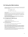
14.0 Using the Web Interface
14.1 Configuring for Web Access
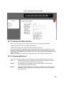
14.1.1 Web Page Layout
14.1.2 Starting the Web Interface
14.1.3 Command Buttons
Glossary
358
358
358
359
359
360
360
360
360
361
361
362
362
363
363
363
365
365
365
366
366
367
21
The information in this guide may change without notice. The manufacturer assumes no
responsibility for any errors, which may appear in this guide.
Ethernet is a trademark of XEROX Corporation. Microsoft, Windows and Windows logo
are trademarks of Microsoft Corporation.
Copyright 2006. All right reserved. No Part of the contents of this guide maybe
transmitted or reproduced in any form or by any means without the written permission of
the manufacturer. Printed in Taiwan.
The revision date for this guide is Mar. 16th, 2006
Version 1.00
FCC Statement
This product has been tested and found to comply with the limits for a Class B digital
device pursuant to Part 15 of FCC Rules. These limits are designed to provide
reasonable protection against such interference when operating in a commercial
environment. This equipment generates, uses and can radiate radio frequency energy,
and if not installed and used according to the instructions, may cause harmful
interference to radio communications.
Operation of this equipment in a residential area is likely to cause interference in which
case the user, at his or her own expense will be required to take whatever measures
may be required to correct the interference.
CE Mark Warning
This is a Class B product. In a domestic environment, this product may cause radio
interference in which case the user may be required to take adequate measures.
22
1.0 Introduction
This manual will apply to the following name of Gigabit Ethernet Management Switch:
Throughout this guide, the Layer2 SNMP Managed Switch will be referred to as the
Managed Switch or the Switch.
Designed as the SNMP managed switch, these series of Switches provide dominant ability
of management and multiple ports. Strictly adhering to the network standards, these
SNMP Managed Switches can easily fit in your network configuration and can be executed
for its management functions through the console and the web browser.
1.1 Package Contents
The package contains the following:
A Managed Switch (According the Model)
One Power Cord
Mounting Brackets
One Serial/Console Cable
CD - User Guide
If any of the listed items is missing or damaged, please contact the place of purchase.
1.2 How to Use this Guide
This user guide is structured as follows:
Chapter 2, Product Description explains the features of the switch and the front/rear
panel indicates
Chapter 3, Installing the Switch explains how to physically install it.
Chapter 4,Command Stucture explains the command’s general format.
Chapter 5, Quick Start up details procedures to quickly become acquainted with the
switch.
Chapter 6, Mode-based Command Line Interface (CLI) groups all the commands in
appropriate modes according to the nature of the commands.
Chapter 7-Chapter 13 lists the format and usage of all commands.
Chapter 14, Using the Web Interface introduces the web screen structure.
23
24
2.0 Installation
This Chapter describes the function of the managed switch components and shows how to
install it on the desktop or shelf. Basic knowledge of networking is assumed. Read this
chapter completely before continuing.
2.1 Product Description
2.1.1 Overview
The SNMP Managed Switches are with powerful network management function and
flexible connectivity combination. Diversified management access windows and
user-friendly interface, Console, Telnet, and Web, facilitate administrators' job, reducing
the management effort to the minimum.
2.1.2 Features of Layer 2 & Layer 3 Switches
z
z
z
z
z
z
z
z
z
z
z
z
z
z
z
z
z
z
z
z
z
z
z
z
z
z
z
z
Half/full duplex mode for ports in 10/100M speed and full duplex mode in 1000Mbps speed
Non-blocking switching architecture.
Flow control mechanism to ensure zero packet loss. Uses IEEE802.3x for full duplex
operation and collision-like backpressure for half duplex operation.
Store-and-forward forwarding scheme.
Port-mirroring function / Multiple Port-mirroring function
Link Aggregation function (2, 3 or 4 ports per link).
Up to 8 trunk group
802.3ad LACP
Broadcast Storm Control
Multicast-filtering. (IGMP snooping)
GVRP protocol for VLAN management.
4092 802.1q Tagged VLAN
Protected port
Rate limit control for both Egress and Ingress (64 Kbps granularity)
802.1x and Radius 802.1x
Layer-4 Access Control List
Spanning Tree protocol (IEEE 802.1D)
802.1w Fast STP
802.1s Multi-STP
Up to 8 units Stacking supported(for Layer 2 switch only)
Class of Service(IEEE 802.1P/802.1Q)
8-level priority for switching
CoS-based Head Of Line (HOL) blocking prevention
Differentiated Service (DiffServ)
Comand line interface from the console port using a VT-100 terminal.
RMON (group 1,2,3 and 9)
MIB II, Ethernet MIB, Bridge MIB and GR-5500 private MIB
WEB-based management
25
z
z
z
z
z
z
z
TELNET console interface
BOOTP for IP address assignment
Firmware upgrade by TFTP file transfer protocol through Ethernet network.
Redundant power supply(optional)
(Layer 3 switch series only)
• Built-in DHCP Server
• DHCP Relay Agent
• L3 IP packets wired-speed Forwarding.
• RIP v1/v2, OSPF v2 for backward compatible
with traditional router
• 4K IPv4,address, 16K Routing table
• Layer 3 wired-speed routing among all ports(IPV4)
• Fully compatible with existing routing protocol:
RIP V1/V2, OSPF V2, PIM, DVMRP.
1 Male DB9 RS-232C console interface configured as DTE for operation, diagnostics, status,
and configuration information.
IEEE 802.3ac frame extension for VLAN tagging.
26
27
28
29
30
2.2 Installing the Switch
The switch is designed for office use, where it can be free standing, desktop-mounted, or
mounted in most standard 19-inch equipment racks. If you prefer, you can rack-mount the
switch in a wiring closet or equipment room using two mounting brackets and six screws.
When choosing a location for the switch, observe the following guidelines:
Make sure the switch is accessible and that the cables can be connected easily.
Keep cabling away from sources of electrical noise such as radios, transmitters, and
broadband amplifiers as well as power lines and fluorescent lighting fixtures.
z Prevent water or moisture from entering the switch case.
z Make sure there are no obstructions to restrict airflow around the switch. We
recommend that you provide a minimum of 50 millimeter (2-inch) clearance.
z Do not place liquids or other objects on top of the switch.
z If the switches are freestanding, do not stack more than four switches on top of one
another.
z
z
2.2.1 Pre-Installation Considerations
Fast Ethernet Topology Considerations
If you will be using the switch for Fast Ethernet (100 Mbps) operation, observe the
following guidelines:
The maximum unshielded twisted-pair (UTP) cable length is 100 meters (328 feet) over
Category 5 cable.
z Single-repeater topologies permit a total network span of 325 meters (1066 feet).
z
Full-Duplex Considerations
The switch provides full-duplex support for its Fast Ethernet ports. Full-duplex operation
allows frames to be sent and received simultaneously, doubling a link’s potential data
throughput. If you will be using the switch in full-duplex mode, the maximum UTP cable
length is 100 meters (328 feet) over Category 5 cable.
2.2.2 Desktop or Shelf Mounting
To install the switch on a desktop or shelf, simply complete the following steps:
Step 1
Step 2
Step 3
Place the switch on a desktop or shelf near an AC power source.
Keep enough ventilation space between the switch and the surrounding objects.
Connect the switch to network devices.
A.
Connect one end of a standard network cable to the 10/100 RJ-45 ports
on the front of the switch.
B.
Connect the other end of the cable to the network devices such as printer
servers, workstations or routers.
Note: It is strongly recommended to use the UTP Category 5 network cabling with RJ-45
tips for the network connection.
31
Step 4
Supply power to the switch.
A.
B.
Connect one end of the power cable to the switch.
Connect the power cube end of the power cable to a standard wall outlet.
When the switch receives power, the Power LED should remain solid Green.
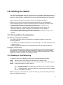
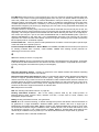
2.2.3 Rack-Mounting
The following procedure describes how to install the switch in a standard 19-inch rack.
z Disconnect all cables from the switch.
z Remove all adhesive pads from the bottom of the switch.
Step 1 Place the switch right side up on a hard flat surface, with the front panel facing you.
Step 2 Locate a mounting bracket over the mounting holes on one side of the switch
Step 3 Insert three screws and use a screwdriver to secure.
Step 4 Repeat the two previous steps for the other side of the switch.
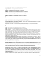
Step 5 Insert the switch into the 19-inch rack and secure with suitable screws. Make sure
the ventilation holes on the switch are not obstructed.
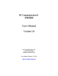
Step 6 Connect the network cable and supply power to the switch.
Figure 1 Locating a Mounting Bracket
2.2.4 Power-On Self Test (POST)
When you power-on the switch, it performs its Power-On Self Test (POST). During the
POST, the switch CPU:
z
Performs a series of diagnostic procedures to make sure the basic system is functioning
32
z
z
with integrity.
Decompresses the main switching software run-time image from the flash ROM into
DRAM area.
Begins executing the main switching software.
33
3.0 Configuration
This chapter explains the methods that you can use to configure management access to
the switch. It describes the types of management applications and the communication and
management protocols that deliver data between your management device (work-station
or personal computer) and the system. It also contains information about port connection
options.
This chapter covers the following topics:
z
z
z
z
z
z
z
Management Access Overview
Key Concepts
Key Guidelines for Implementation
Administration Console Access
Web Management Access
SNMP Access
Standards, Protocols, and Related Reading
3.1 Management Access Overview
The switch gives you the flexibility to access and manage the switch using any or all of the
following methods:
z
z
z
An administration console
Web browser interface
An external SNMP-based network management application
The administration console and Web browser interface support are embedded in the
switch software and are available for immediate use. Each of these management methods
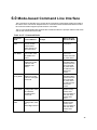
has their own advantages. Table 4 compares the three management methods.
Table 1 Comparisons of Three Management Methods
Management
Method
Advantages
z No IP address or subnet
needed
z Text-based
z Telnet functionality and
Administration
HyperTerminal built into
console
Windows
95/98/NT/2000/ME/XP
operating systems
z Secure
z Ideal for configuring the
switch remotely
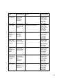
Web browser
z Compatible with all
Disadvantages
z Must be near switch or use
dial-up connection
z Not convenient for remote users
z Modem connection may prove to
be unreliable or slow
z Security can be compromised
(hackers need only know the IP
address and subnet mask)
34
z May encounter lag times on poor
popular browsers
connections
z Can be accessed from
any location
z Most visually appealing
z Communicates with
z Requires SNMP manager
switch functions at the
software
MIB level
z Least visually appealing of all
z Based on open standards
three methods
SNMP Agent
z Some settings require
calculations
z Security can be compromised
(hackers need only know the
community name)
3.1.1 Administration Console
The administration console is an internal, character-oriented, and command line user
interface for performing system administration such as displaying statistics or changing
option settings. Using this method, you can view the administration console from a
terminal, personal computer, Apple Macintosh, or workstation connected to the switch’s
console (serial) port.
There are two ways to use this management method: via direct access or modem port
access. The following sections describe these methods. For more information about using
the console, refer to Chapter 4 Command Line Interface Console Management.
3.1.2 Direct Access
Direct access to the administration console is achieved by directly connecting a terminal or
a PC equipped with a terminal-emulation program (such as HyperTerminal) to the switch
console (serial) port.
When using this management method, a null-modem cable is required to connect the
switch to the PC. After making this connection, configure the terminal-emulation program
to use the following parameters:
The default parameters are:
z
115,200 bps
z
8 data bits
z
No parity
z
1 stop bit
You can change these settings, if desired, after you log on. This management method is
often preferred because you can remain connected and monitor the system during system
reboots. Also, certain error messages are sent to the serial port, regardless of the interface
through which the associated action was initiated. A Macintosh or PC attachment can use
any terminal-emulation program for connecting to the terminal serial port. A workstation
35
attachment under UNIX can use an emulator such as TIP.
3.2 Web Management
The switch provides a browser interface that lets you configure and manage the switch
remotely. After you set up your IP address for the switch, you can access the switch’s Web
interface applications directly in your Web browser by entering the IP address of the switch.
You can then use your Web browser to list and manage switch configuration parameters
from one central location, just as if you were directly connected to the switch’s console
port.
Web Management requires either Microsoft Internet Explorer 4.01 or later or Netscape
Navigator 4.03 or later.
3.3 SNMP-Based Network Management
You can use an external SNMP-based application to configure and manage the switch.
This management method requires the SNMP agent on the switch and the SNMP Network
Management Station to use the same community string. This management method, in fact,
uses two community strings: the get community string and the set community string. If the
SNMP Net-work management Station only knows the set community string, it can read
and write to the MIBs. However, if it only knows the get community string, it can only read
MIBs. The default gets and sets community strings for the switch are public.
3.4 Protocols
The switch supports the following protocols:
z
z
Virtual terminal protocols, such as Telnet
Simple Network Management Protocol (SNMP)
3.4.1 Virtual Terminal Protocols
A virtual terminal protocol is a software program, such as Telnet, that allows you to
establish a management session from a Macintosh, a PC, or a UNIX workstation. Because
Telnet runs over TCP/IP, you must have at least one IP address configured on the switch
before you can establish access to it with a virtual terminal protocol.
Note: Terminal emulation differs from a virtual terminal protocol in that you must connect a
terminal directly to the console (serial) port.
3.4.2 SNMP Protocol
Simple Network Management Protocol (SNMP) is the standard management protocol for
multi-vendor IP networks. SNMP supports transaction-based queries that allow the protocol to
format messages and to transmit information between reporting devices and data-collection
programs. SNMP runs on top of the User Datagram Protocol (UDP), offering a
connectionless-mode service.
36
3.4.3 Management Architecture
All of the management application modules use the same Messaging Application
Programming Interface (MAPI). By unifying management methods with a single
MAPI, configuration parameters set using one method (console port, for example)
are immediately displayable by the other management methods (for example,
SNMP agent of Web browser).
The management architecture of the switch adheres to the IEEE open standard.
This compliance assures customers that the switch is compatible with, and will
interoperate with other solutions that adhere to the same open standard.
37
4.0 Command Structure
The Command Line Interface (CLI) syntax, conventions and terminology are described in
this section. Each CLI command referenced in this document is illustrated using the
structure outlined below.
4.1 Format
Some commands, such as show inventory or clear vlan,do not require parameters. Other
commands, such as network parms , have parameters for which you must supply a value.
Parameters are positional — you must type the values in the correct order. Optional
parameters will follow required parameters. For example:
Example 1
network parms <ipaddr> <netmask> [gateway]
network parms is the command name.
<ipaddr> <netmask> are the required values for the command.
[gateway] is the optional value for the command.
Example 2
snmp-server location <loc>
snmp-server location is the command name.
<loc> is the required parameter for the command.
Example 3
clear vlan
clear vlan is the command name.
4.1.1 Command
The following conventions apply to the command name:
The command name is displayed in this document in bold font and must be typed
exactly as shown.
Once you have entered enough letters of a command name to uniquely identify the
command, hitting the space bar or Tab key will cause the system to complete the
word.
Entering Ctrl-Z will return you to the root level command prompt.
4.1.2 Parameters
Parameters are order dependent.
38
Parameters are displayed in this document in bold italic font, which must be
replaced with a name or number. To use spaces as part of a name parameter,
enclose it in double quotes. For example, the expression "System Name with
Spaces" forces the system to accept the spaces.
Parameters may be mandatory values, optional values, choices, or a combination.
<parameter>. The <> angle brackets indicate that a mandatory parameter must
be entered in place of the brackets and text inside them.
[parameter]. The [] square brackets indicate that an optional parameter may be
entered in place of the brackets and text inside them.
choice1 | choice2. The | indicates that only one of the parameters should be
entered.
The {} curly braces indicate that a parameter must be chosen from the list
of choices.
4.1.3 Values
ipaddr
This parameter is a valid IP address. Presently the IP address can
be entered in following formats: a (32 bits)
a.b (8.24 bits)
a.b.c (8.8.16 bits)
a.b.c.d (8.8.8.8)
In addition to these formats, decimal, hexidecimal and octal formats are
supported through the following input formats (where n is any valid
hexidecimal, octal or decimal number):
0xn (CLI assumes hexidecimal format)
0n (CLI assumes octal format with leading zeros)
n (CLI assumes decimal format)
macaddr The MAC address format is six hexadecimal numbers separated by
colons, for example 00:06:29:32:81:40.
areaid
Area IDs may be entered in dotted-decimal notation (for example,
0.0.0.1). An area ID of 0.0.0.0 is reserved for the backbone. Area
IDs have the same form as IP addresses, but are distinct from IP
addresses. The IP network number of the sub-netted network may
be used for the area ID.
routerid
The value of <router id> must be entered in 4-digit
dotted-decimal notation (for example, 0.0.0.1). A router ID of
0.0.0.0 is invalid.
Valid unit, slot and port number separated by forward slashes.
For example, 1/0/1 represents unit number 1, slot number 0 and
port number 1.
unit/slot/port
Logical unit, slot and port number. This is applicable
in the case of a port-channel (LAG). The operator can use the
logical unit/slot/port to configure the port-channel.
logical unit/slot/port
39
character strings Use double quotation marks to identify character strings,
for example, “System Name with Spaces”. An empty string (“”) is
not valid.
4.1.4 Conventions
Network addresses are used to define a link to a remote host, workstation or
network. Network addresses are shown using the following syntax:
Table 1. Network Address Syntax
Address Type
Format
Range
ipaddr
192.165.11.110
0.0.0.0 to 255.255.255.255
(decimal)
macaddr
A7:C9:89:DD:A9:B3
hexidecimal digit pairs
Double quotation marks such as "System Name with Spaces" set off user defined
strings. If the operator wishes to use spaces as part of a name parameter then it
must be enclosed in double quotation marks.
Empty strings (““) are not valid user defined strings.
Command completion finishes spelling the command when enough letters of a command are typed to uniquely identify the command word. The command may be executed by typing <enter> (command abbreviation) or the command word may be
completed by typing the <tab> or <space bar> (command completion). The value
'Err' designates that the requested value was not internally accessible. This should
never happen and indicates that there is a case in the software that is not handled
correctly.
The value of '-----' designates that the value is unknown.
4.1.5 Annotations
The CLI allows the user to type single-line annotations at the command prompt for use
when writing test or configuration scripts and for better readability. The exclamation point
(‘!’) character flags the beginning of a comment. The comment flag character can begin a
word anywhere on the command line and all input following this character is ignored. Any
command line that begins with the character ‘!’ is recognized as a comment line and
ignored by the parser.
Some examples are provided below:
! Script file for displaying the ip interface
! Display information about interfaces
40
show ip interface 1/0/1 !Displays the information about the first interface
! Display information about the next interface
show ip interface 1/0/2
! End of the script file
4.1.6 Special Characters
Certain special key combinations speed up use of the CLI. They are listed in this section.
Also, help is available for the CLI by typing HELP.
DEL, BS delete previous character
Ctrl-A
go to beginning of line
Ctrl-E
go to end of line
Ctrl-F go forward one character
Ctrl-B
go backward one character
Ctrl-D
delete current character
Ctrl-H
display command history or retrieve a command
Ctrl-U, X delete to beginning of line
Ctrl-K
delete to end of line
Ctrl-W
delete previous word
Ctrl-T transpose previous character
Ctrl-P
go to previous line in history buffer
Ctrl-N
go to next line in history buffer
Ctrl-Z return to root command prompt
Tab, <SPACE> command-line completion
Exit
to exit from the mode to the upper lower command prompt
41
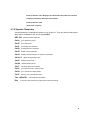
5.0 Quick Start up
The CLI Quick Start up details procedures to quickly become acquainted with the
the switch’s managed commands.
5.1 Quick Starting the Networking Device
1.
2.
3.
4.
Read the Chapter 2.0 for the connectivity procedure. In-band connectivity allows
access to the Web and CLI command interface locally or from a remote
workstation. The device must be configured with IP information (IP address,
subnet mask, and default gateway).
Turn the Power ON.
Allow the device to load the software until the login prompt appears. The device
initial state is called the default mode
When the prompt asks for operator login, execute the following steps:
Type the word admin in the login area. Since a number of the Quick Setup commands
require administrator account rights, we suggests logging into an administrator account.
Do not enter a password because there is no password in the default mode.
Press the enter key two times.
The CLI User EXEC prompt will be displayed.
Use “enable” to networking device to the Privileged EXEC mode from User EXEC.
Use “configure” to switch to the Global Config mode from Privileged EXEC.
Use “exit” to return to the previous mode.
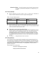
5.2 System Info and System Setup
Quick Start up Software Version Information
Table 2 Quick Start up Software Version Information
Command
show hardware
(in Privileged EXEC)
Details
Allows the user to see the software version the device contains
Machine Model (The type and number of ports the device
provides.)
For example:
Machine Model…………. 24+2G
24 = 24 10/100 ports
02 = 2 Uplink ports on back of switch
42
Quick Start up Physical Port Data
Table 3 Quick Start up Physical Port Data
Command
show port all
(in Privileged
EXEC)
Details
Displays the Ports
slot/port
Type - Indicates if the port is a special type of port
Admin Mode - Selects the Port Control Administration State
Physical Mode - Selects the desired port speed and duplex mode
Physical Status - Indicates the port speed and duplex mode
Link Status - Indicates whether the link is up or down
Link Trap - Determines whether or not to send a trap when link
status changes
LACP Mode - Displays whether LACP is enabled or disabled on this
port.
Quick Start up User Account Management
Table 4 Quick Start up User Account Management
Command
show users
(in Privileged EXEC)
show loginsession
(in User EXEC)
users passwd <username>
(in Global Config)
copy
system:running-config
nvram:startup-config
(in Privileged EXEC)
logout
(in User EXEC and
Privileged EXEC)
Details
Displays all of the users that are allowed to access the
switch
Access Mode - Shows whether the user is able to change
parameters on the switch (Read/Write) or is only able to
view then (Read Only).
As a factory default, the ‘admin’ user has Read/Write access
and the ‘guest’ user has Read Only access. There can only
be one Read/Write user and up to five Read Only users.
Displays all of the login session information
Allows the user to set passwords or change passwords
needed to login
A prompt will appear after the command is entered
requesting the users old password. In the absence of an old
password leave the area blank. The operator must press
enter to execute the command.
The system then prompts the user for a new password then
a prompt to confirm the new password. If the new password
and the confirmed password match a message will be
displayed.
User password should not be more than eight characters in
length.
This will save passwords and all other changes to the
device.
If you do not save the configuration by doing this command,
all configurations will be lost when a power cycle is
performed on the switch or when the switch is reset
Logs the user out of the switch
43
Quick Start up IP Address
To view the network parameters the operator can access the device by the following three
methods.
Simple Network Management Protocol - SNMP
Telnet
Web Browser
Note: Helpful Hint: The user should do a ‘copy system:running-config nvram:startup-config’
after configuring the network parameters so that the configurations are not lost
Table 5 Quick Start up IP Address
Command
show network
(in User EXEC)
Details
Displays the Network Configurations
IP Address - IP Address of the interface
Default IP is 0.0.0.0
Subnet Mask - IP Subnet Mask for the interface
Default is 0.0.0.0
Default Gateway - The default Gateway for this interface
Default value is 0.0.0.0
Burned in MAC Address - The Burned in MAC Address used for
in-band connectivity
Locally Administered MAC Address - Can be configured to allow a
locally administered MAC address
MAC Address Type - Specifies which MAC address should be
used for in-band connectivity
Network Configurations Protocol Current - Indicates which network
protocol is being used
Default is none
Management VLAN Id - Specifies VLAN id
Web Mode - Indicates whether HTTP/Web is enabled.
Java Mode - Indicates whether java mode is enabled.
network parms
(in Privileged
EXEC)
network parms <ipaddr> <netmask> [<gateway>]
IP Address range from 0.0.0.0 to 255.255.255.255
Subnet Mask range from 0.0.0.0 to 255.255.255.255
Gateway Address range from 0.0.0.0 to 255.255.255.255
44
Quick Start up Uploading from Switch to Out-of-Band PC (Only XMODEM)
Table 6 Quick Start up Uploading from Switch to Out-of-Band PC (XMODEM)
Command
copy {
nvram:startup-config
|
nvram:errorlog |
nvram:msglog |
nvram:traplog} <url>
Details
The types are:
config - configuration file
errorlog - error log
system trace - system trace
traplog - trap log
The URL must be specified as:
xmodem:filepath/fileName
This starts the upload and also displays the mode of uploading
and the type of upload it is and confirms the upload is taking
place.
For example:
If the user is using HyperTerminal, the user must
specify where the file is going to be received by the
PC.
Quick Start up Downloading from Out-of-Band PC to Switch (Only XMODEM)
Table 7 Quick Start up Downloading from Out-of-Band PC to Switch (Only XMODEM)
Command
copy <url>
{nvram:startup-config
| system: image}
Details
Sets the destination (download) data type to be an image
(system:image) or a configuration file (nvram:startup-config).
The URL must be specified as:
xmodem:filepath/fileName
For example:
If the user is using HyperTerminal, the user must specify which
file is to be sent to the switch.
The Switch will restart automatically once the code has been
downloaded.
Quick Start up Downloading from TFTP Server
Before starting a TFTP server download, the operator must complete the Quick Start up
for the IP Address.
Table 8 Quick Start up Downloading from TFTP Server
Command
copy <url>
{nvram:startup-config | system:
image}
Details
Sets the destination (download) data type to be an
image (system:image) or a configuration file
(nvram:startup-config).
The URL must be specified as:
tftp://ipAddr/filepath/fileName.
The nvram:startup-config option downloads the
configuration file using tftp and system:image option
downloads the code file.
45
Quick Start up Factory Defaults
Table 9 Quick Start up Factory Defaults
Command
clear config
copy system:running-config
nvram:startup-config
reload OR Cold Boot the
Switch
Details
Enter yes when the prompt pops up to clear all the
configurations made to the switch.
Enter yes when the prompt pops up that asks if you
want to save the configurations made to the switch.
Enter yes when the prompt pops up that asks if you
want to reset the system.
This is the users choice either reset the switch or cold
boot the switch, both work effectively.
46
6.0 Mode-based Command Line Interface
The Command Line Interface (CLI) groups all the commands in appropriate modes according to
the nature of the commands. Sample of the CLI command modes are described below. Each of
the command modes supports specific switch’s commands.
The CLI Command Modes table captures the command modes, the prompts visible in that mode
and the exit method from that mode.
Table 10. CLI Command Modes
Command
Mode
Exit or Access
Previous Mode
Access Method
Prompt
User Exec
Mode
This is the first
level of access.
Perform basic
tasks and list system information.
Switch>
Enter Logout
command
Privileged
Exec Mode
From the User
Exec mode, enter
the enable command.
Switch#
To exit to the
User Exec
mode, enter exit
or press Ctrl-Z.
VLAN Mode
From the Privileged Exec mode,
enter the vlan
database command.
Switch (Vlan) #
Global
Config Mode
From the Privileged Exec mode,
enter the con-figure
command.
Switch (Config)#
Interface
Config Mode
From the Global
Config mode, enter
the inter-face
<unit/slot/ port>
command.
Switch (Interface "if number")#
Line Config
Mode
From the Global
Config mode, enter
the
lineconfigcommand
Switch (line) #
To exit to the
Privileged Exec
mode, enter the
exit command,
or press Ctrl-Z
to switch to the
User Exec
mode.
To exit to the
Privileged Exec
mode, enter the
exit command,
or press Ctrl-Z
to switch to the
User Exec
mode.
To exit to the
Global Config
mode, enter
exit. To return to
the User Exec
mode, enter
ctrl-Z.
To exit to the
Global Config
mode, enter
exit. To return to
the User Exec
mode, enter
ctrl-Z.
47
Command
Mode
Policy Map
Con-fig Mode
Access Method
Prompt
From the Global
Config mode,
enter the
Switch (Config-policy-map)#
pol-icy-map
command
Policy Class
Config Mode
From the Policy
Map mode enter
the class command
Switch
(Config-policy-classmap)#
Class Map
Con-fig
Mode(only for
Layer 3
Series)
From the Global
Config mode,
enter the
Switch (Config-classmap)#
class-map
command
Router OSPF
Config Mode
(only for Layer
3 Series)
From the Global
Config mode,
enter the router
ospf command
Switch (Config-router)#
Router RIP
Config
Mode(only for
Layer 3
Series)
From the Global
Config mode,
enter the router
rip command
Switch (Config-router)#
Router BGP
Config Mode
(only for Layer
3 Series)
From the Global
Config mode,
enter the router
Switch (Config-router)#
bgp
<asnum-ber>
command
Bwprovisioning
Config Mode
From the Global
Config mode,
enter the
bwpro-visioning
command.
Switch (Config-bwp)#
Exit or Access
Previous Mode
To exit to the
Global Config
mode, enter
exit. To return
to the User
Exec mode,
enter ctrl-Z.
To exit to the
Policy Map
mode, enter
exit. To return
to the User
Exec mode,
enter ctrl-Z.
To exit to the
Global Config
mode, enter
exit. To return
to the User
Exec mode,
enter ctrl-Z.
To exit to the
Global Config
mode, enter
exit. To return
to the User
Exec mode,
enter ctrl-Z.
To exit to the
Global Config
mode, enter
exit. To return
to the User
Exec mode,
enter ctrl-Z.
To exit to the
Global Config
mode, enter
exit. To return
to the User
Exec mode,
enter ctrl-Z.
To exit to the
Global Config
mode, enter
exit. To return
to the User
Exec mode,
enter ctrl-Z.
48
Command
Mode
Access Method
Prompt
Bwprovisioning
- Trafficclass
Con-fig Mode
From the Bwprovisioning mode,
enter the
traf-fic-class command.
Switch
(Config-bwp-trafficclass)#
Bwprovisioning
- bwallocation
Config Mode
From the Bwprovisioning mode,
enter the
Switch
(Config-bwp-bwallocation)#
bwal-location
command.
MAC
Access-list
Config Mode
From the Global
Config mode
enter the mac
Switch
(Config-mac-access-list)#
access-list
extended <name>
command
DHCP Pool
Con-fig Mode
From the Global
Config mode,
enter the ipdhcp
pool<pool-name>
command.
Switch (Config-dhcp-pool)#
Stack Global
Config Mode
From the Global
Config mode,
enter the stack
command.
Switch (Config-stack )#
Exit or Access
Previous Mode
To exit to the
Bwprovisioning
Config mode,
enter exit. To
return to the
User Exec
mode, enter
ctrl-Z.
To exit to the
Bwprovisioning
mode, enter
exit. To return
to the User
Exec mode,
enter ctrl-Z.
To exit to the
Global Config
mode, enter
exit. To return
to the User
Exec mode,
enter ctrl-Z.
To exit to the
Global Config
mode, enter
exit. To return
to the User
Exec mode,
enter ctrl-Z
To exit to the
Global Config
mode, enter
exit. To return
to the User
Exec mode,
enter ctrl-Z
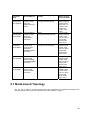
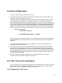
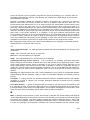
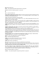
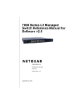
6.1 Mode-based Topology
The CLI tree is built on a mode concept where the commands are available according to the
interface. Some of the modes are depicted in the mode-based CLI Figure 1.
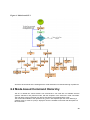
49
Figure 1. Mode-based CLI
Access to all commands in the Privileged Exec mode and below are restricted through a password.
6.2 Mode-based Command Hierarchy
The CLI is divided into various modes. The Commands in one mode are not available until the
operator switches to that particular mode, with the exception of the User Exec mode commands.
The User Exec mode commands may also be executed in the Privileged Exec mode.
The commands available to the operator at any point in time depend upon the mode. Entering a
question mark (?) at the CLI prompt, displays a list of the available commands and descriptions of
the commands.
50
The CLI provides the following modes:
User Exec Mode
When the operator logs into the CLI, the User Exec mode is the initial mode. The User Exec
mode contains a limited set of commands. The command prompt shown at this level is:
Command Prompt: $>
Privileged Exec Mode
To have access to the full suite of commands, the operator must enter the Privileged Exec
mode. The Privileged Exec mode requires password authentication. From Privileged Exec
mode, the operator can issue any Exec command, enter the VLAN mode or enter the Global
Configuration mode . The command prompt shown at this level is:
Command Prompt: $#
VLAN Mode
This mode groups all the commands pertaining to VLANs. The command prompt shown at this
level is:
Command Prompt: $(VLAN)#
Global Config Mode
This mode permits the operator to make modifications to the running configuration. General setup
commands are grouped in this mode. From the Global Configuration mode, the operator can
enter the System Configuration mode, the Physical Port Configuration mode, the Interface
Configuration mode, or the Protocol Specific modes specified below. The command prompt at
this level is:
Command Prompt: $(Config)#
From the Global Config mode, the operator may enter the following configuration modes:
Interface Config Mode
Many features are enabled for a particular interface. The Interface commands enable or modify
the operation of an interface.In this mode, a physical port is set up for a specific logical
connection operation. The Interface Config mode provides access to the router interface
configuration commands. The command prompt at this level is:
Command Prompt: $(Interface <unit/slot/port>)#
The resulting prompt for the interface configuration command entered in the Global Configuration
mode is shown below:
$(Config)# interface 1/2/1
$(Interface 1/2/1)#+
51
Line Config Mode
This mode allows the operator to configure the console interface. The operator may configure the
interface from the directly connected console or the virtual terminal used with Telnet. The
command prompt at this level is:
Command Prompt: $(Line)#
Policy Map Mode
Use the policy-map <policy-name>command to access the QoS policy map configuration
mode to configure the QoS policy map.
$(Config)# policy map <policy name> Command
Prompt: $(Config-policy-map)#
Policy Class Mode
Use the class <class-name> command to access the QoS policy-classmap mode to attach/
remove a diffserv class to a policy and to configure the QoS policy class.
$(Config policy-map)# class <class name> Command
Prompt: $(Config-policy-classmap)#
Class Map Mode:
This mode consists of class creation/deletion and matching commands. The class match commands specify Layer 2, Layer 3 and general match criteria. Use the class-map class-map-name
commands to access the QoS class map configuration mode to configure QoS class maps.
$(Config)# class-map <class-map-name> Command
Prompt: $(Config class-map)#
Router OSPF Config Mode:
In this mode, the operator is allowed to access the router OSPF configuration commands. The
command prompt at this level is:
$(Config)# router ospf Command Prompt:
$(Config router)#
Router RIP Config Mode:
In this mode, the operator is allowed to access the router RIP configuration commands. The
command prompt at this level is:
$(Config)# router rip Command Prompt:
$(Config router)#
Router BGP Config Mode:
In this mode, the operator is allowed to access the router BGP4 configuration commands. The
command prompt at this level is:
$(Config)# router bgp <1-65535> Command
52
Prompt: $(Config-routerbgp)#
Bwprovisioning Config Mode
Use the bwprovisioning command to access the Bandwidth provisioning Config Mode to configure
bandwidth provisioning.
$(Config)# bwprovisioning Command
Prompt: $(Config-bwp)#
Bwprovisioning Trafficclass Mode
Use the traffic-class command to access the Bandwidth provisioning Config Mode to configure
bandwidth traffic class.
$(Config bwp)# traffic-classCommand Prompt: $(Config-bwp-trafficclass)#
Bwprovisioning bwallocation Mode
Use the bwallocation command to access the Bandwidth provisioning Config Mode to
configure bandwidth allocation.
$(Config bwp)# bwallocation
Command Prompt: $(Config bwp-bwallocation)#
MAC Access-List Config Mode
Use the MAC Access-List Config mode to create a MAC access-List and to enter the mode
containing mac access-list configuration commands.
$(Config)#mac-access-list extended <name>
Command Prompt: $(Config-mac-access-list)#
DHCP Pool Config Mode
Use the ip dhcp pool <pool-name> command to access the DHCP Pool Config .
$(Config)# ip dhcp pool <pool-name>
Command Prompt: (Config-dhcp-pool)#
Stack Global Config Mode
Use the stack command to access the Stack Config Mode.
$(Config)# stack
Command Prompt: (Config-stack)#
53
6.3 Flow of Operation
This section captures the flow of operation for the CLI:
1. The operator logs into the CLI session and enters the User Exec mode. In the User Exec mode
the $(exec)> prompt is displayed on the screen.
The parsing process is initiated whenever the operator types a command and presses <ENTER>.
The command tree is searched for the command of interest. If the command is not found, the
output message indicates where the offending entry begins. For instance, command node A has
the command "show arp brief" but the operator attempts to execute the command "show arpp brief"
then the output message would be $(exec)> show arpp brief^. $%Invalid input detected at '^'
marker. If the operator has given an invalid input parameter in the command, then the message
conveys to the operator an invalid input was detected. The layout of the output is depicted below:
Syntax Error Message:
(exec) #show arpp brief
^
%Invalid input detected at ‘^’ marker.
After all the mandatory parameters are entered, any additional parameters entered are treated as
optional parameters. If any of the parameters are not recognized a syntax error message will be
displayed.
2. After the command is successfully parsed and validated, the control of execution goes to the
corresponding CLI callback function.
3. For mandatory parameters, the command tree extends till the mandatory parameters make the
leaf of the branch. The callback function is only invoked when all the mandatory parameters are
provided. For optional parameters, the command tree extends till the mandatory parameters and
the optional parameters make the leaf of the branch. However, the call back function is associated
with the node where the mandatory parameters are fetched. The call back function then takes
care of the optional parameters.
4. Once the control has reached the callback function, the callback function has complete
information about the parameters entered by the operator.
6.4 “No” Form of a Command
“No” is a specific form of an existing command and does not represent a new or distinct command.
Only the configuration commands are available in the “no” form. The behavior and the support
details of the “no” form is captured as part of the mapping sheets.
6.4.1 Support for “No” Form
54
Almost every configuration command has a “no” form. In general, use the no form to reverse the
action of a command or reset a value back to the default. For example, the no shutdown interface
configuration command reverses the shutdown of an interface. Use the command without the
keyword no to re-enable a disabled feature or to enable a feature that is disabled by default.
55
7.0 Switching Commands
This chapter provides detailed explanation of the Switching commands. The commands are divided
into five functional groups:
Show commands display switch settings, statistics, and other information.
Configuration commands configure features and options of the switch. For every
configuration command, there is a show command that displays the configuration setting.
Copy commands transfer or save configuration and informational files to and from the switch.
Clear commands clear some or all of the settings to factory defaults.
This chapter includes the following configuration types:
System information and statistics commands
System Management commands
Device configuration commands
User account management commands
Security commands
System utilities
7.1 System Information and Statistics Commands
This chapter provides a detailed explanation of the CLI commands. The commands are
divided into five functional groups:
Show commands display switch settings, statistics, and other information.
Configuration commands configure features and options of the switch. For every
configuration command, there is a show command that displays the configuration setting.
Copy commands transfer or save configuration and informational files to and from the
switch.
Clear commands clear some or all of the settings to factory defaults.
7.1.1 show arp switch
This command displays connectivity between the switch and other devices. The Address
Resolution Protocol (ARP) cache identifies the MAC addresses of the IP stations communicating
with the switch.
Format
Mode
show arp switch
Privileged EXEC
MAC Address
A unicast MAC address for which the switch has forwarding and/or filtering
information. The format is 6 two-digit hexadecimal numbers that are separated by colons, for
example 01:23:45:67:89:AB
IP Address The IP address assigned to each interface.
unit/slot/port Valid unit, slot and port number separated by forward slashes.
56
7.1.2 show eventlog
This command displays the event log, which contains error messages from the system. The event
log is not cleared on a system reset.
Format
Mode
show eventlog
Privileged EXEC
File
The file in which the event originated.
Line
The line number of the event.
Task Id The task ID of the event.
Code The event code.
Time The time this event occurred.
Note: Event log information is retained across a switch reset.
7.1.3 show hardware
This command displays inventory information for the switch.
Format
Mode
show hardware
Privileged EXEC
Switch Description
Text used to identify the product name of this switch.
Machine Type Specifies the machine model as defined by the Vital Product Data.
Machine Model Specifies the machine model as defined by the Vital Product Data.
Serial Number The unique box serial number for this switch.
FRU Number The field replaceable unit number.
Part Number Manufacturing part number.
Maintenance Level Indicates hardware changes that are significant to software.
Manufacturer
Manufacture descriptor field.
Burned in MAC Address Universally assigned network address.
Software Version
The release version revision number of the code currently running on the
switch.
Operating System
The operating system currently running on the switch.
Network Processing Element The type of the processor micro-code.
Additional Packages
This displays the additional packages that are incorporated into this
system, such as BGP-4, or Multicast.
7.1.4 show interface
This command displays a summary of statistics for a specific port or a count of all CPU traffic
based upon the argument.
57
Format
Mode
show interface {<unit/slot/port> | switchport}
Privileged EXEC
The display parameters, when the argument is ' <unit/slot/port>', is as follows :
Packets Received Without Error The total number of packets (including broadcast packets
and multicast packets) received by the processor.
The number of inbound packets that contained errors
Packets Received With Error
preventing them from being deliverable to a higher-layer protocol.
Broadcast Packets Received The total number of packets received that were directed to the
broadcast address. Note that this does not include multicast packets.
Packets Transmitted Without Error The total number of packets transmitted out of the
interface.
Transmit Packets Errors The number of outbound packets that could not be transmitted
because of errors.
Collisions Frames The best estimate of the total number of collisions on this Ethernet segment.
Time Since Counters Last Cleared The elapsed time, in days, hours, minutes, and seconds
since the statistics for this port were last cleared.
The display parameters, when the argument is 'switchport', is as follows :
Packets Received Without Error The total number of packets (including broadcast packets
and multicast packets) received by the processor.
Broadcast Packets Received The total number of packets received that were directed to the
broadcast address. Note that this does not include multicast packets.
The number of inbound packets that contained errors
Packets Received With Error
preventing them from being deliverable to a higher-layer protocol.
The total number of packets transmitted out of the
Packets Transmitted Without Error
interface.
Broadcast Packets Transmitted The total number of packets that higher-level protocols
requested to be transmitted to the Broadcast address, including those that were
discarded or not sent.
Transmit Packet Errors The number of outbound packets that could not be transmitted
because of errors.
Address Entries Currently In Use
The total number of Forwarding Database Address Table
entries now active on the switch, including learned and static entries.
VLAN Entries Currently In Use The number of VLAN entries presently occupying the VLAN
table.
Time Since Counters Last Cleared The elapsed time, in days, hours, minutes, and seconds
since the statistics for this switch were last cleared.
7.1.5 show interface ethernet
This command displays detailed statistics for a specific port or for all CPU traffic based upon
the argument.
58
Format
Mode
show interface ethernet {<unit/slot/port> | switchport}
Privileged EXEC
The display parameters, when the argument is '<unit/slot/port>', are as follows :
Packets Received
Octets Received - The total number of octets of data (including those in bad packets)
received on the network (excluding framing bits but including Frame Check Sequence
(FCS) octets). This object can be used as a reasonable estimate of ethernet utilization. If
greater precision is desired, the etherStatsPkts and etherStatsOctets objects should be
sampled before and after a common interval. ----- The result of this
equation is the value Utilization which is the percent utilization of the ethernet segment on
a scale of 0 to 100 percent.Packets Received < 64 Octets - The total number of packets
(including bad packets)
received that were < 64 octets in length (excluding framing bits but including FCS
octets).
Packets Received 64 Octets - The total number of packets (including bad packets)
received that were 64 octets in length (excluding framing bits but including FCS octets).
Packets Received 65-127 Octets - The total number of packets (including bad packets)
received that were between 65 and 127 octets in length inclusive (excluding framing bits
but including FCS octets).
Packets Received 128-255 Octets - The total number of packets (including bad packets)
received that were between 128 and 255 octets in length inclusive (excluding framing bits
but including FCS octets).
Packets Received 256-511 Octets - The total number of packets (including bad packets)
received that were between 256 and 511 octets in length inclusive (excluding framing bits
but including FCS octets).
Packets Received 512-1023 Octets - The total number of packets (including bad
packets) received that were between 512 and 1023 octets in length inclusive (excluding
framing bits but including FCS octets).
Packets Received 1024-1518 Octets - The total number of packets (including bad
packets) received that were between 1024 and 1518 octets in length inclusive (excluding
framing bits but including FCS octets).
Packets Received 1519-1522 Octets - The total number of packets (including bad
packets) received that were between 1519 and 1522 octets in length inclusive (excluding
framing bits but including FCS octets).
Packets Received > 1522 Octets - The total number of packets received that were
longer than 1522 octets (excluding framing bits, but including FCS octets) and were
otherwise well formed.
Packets Received Successfully
Total - The total number of packets received that were without errors.
Unicast Packets Received - The number of subnetwork-unicast packets delivered to
a higher-layer protocol.
Multicast Packets Received - The total number of good packets received that were
directed to a multicast address. Note that this number does not include packetsdirected
to the broadcast address.
Broadcast Packets Received - The total number of good packets received that were
directed to the broadcast address. Note that this does not include multicast packets.
Packets Received with MAC Errors
59
Total - The total number of inbound packets that contained errors preventing them from
being deliverable to a higher-layer protocol.
Jabbers Received - The total number of packets received that were longer than 1518
octets (excluding framing bits, but including FCS octets), and had either a bad Frame
Check Sequence (FCS) with an integral number of octets (FCS Error) or a bad FCS with
a non-integral number of octets (Alignment Error). Note that this definition of jabber is
different than the definition in IEEE-802.3 section 8.2.1.5 (10BASE5) and section 10.3.1.4
(10BASE2). These documents define jabber as the condition where any packet exceeds
20 ms. The allowed range to detect jabber is between 20 ms and 150 ms.
Fragments/Undersize Received - The total number of packets received that were
less than 64 octets in length (excluding framing bits but including FCS octets).
Alignment Errors - The total number of packets received that had a length (excluding
framing bits, but including FCS octets) of between 64 and 1518 octets, inclusive, but had
a bad Frame Check Sequence (FCS) with a non-integral number of octets.
Rx FCS Errors - The total number of packets received that had a length (excluding
framing bits, but including FCS octets) of between 64 and 1518 octets, inclusive, but had
a bad Frame Check Sequence (FCS) with an integral number of octets
Overruns - The total number of frames discarded as this port was overloaded with
incoming packets, and could not keep up with the inflow.
Received Packets not forwarded
Total - A count of valid frames received which were discarded (i.e. filtered) by the
forwarding process.
Local Traffic Frames - The total number of frames dropped in the forwarding process
because the destination address was located off of this port.
802.3x Pause Frames Received - A count of MAC Control frames received on this
interface with an op-code indicating the PAUSE operation. This counter does not
increment when the interface is operating in half-duplex mode.
Unacceptable Frame Type - The number of frames discarded from this port due to
being an unacceptable frame type.
VLAN Membership Mismatch - The number of frames discarded on this port due to
ingress filtering.
VLAN Viable Discards - The number of frames discarded on this port when a lookup on
a particular VLAN occurs while that entry in the VLAN table is being modified, or if the
VLAN has not been configured.
Multicast Tree Viable Discards - The number of frames discarded when a lookup in the
multicast tree for a VLAN occurs while that tree is being modified.
Reserved Address Discards - The number of frames discarded that are destined to an
IEEE 802.1 reserved address and are not supported by the system.
Broadcast Storm Recovery - The number of frames discarded that are destined for
FF:FF:FF:FF:FF:FF when Broadcast Storm Recovery is enabled.
CFI Discards - The number of frames discarded that have CFI bit set and the
addresses in RIF are in non-canonical format.
Upstream Threshold - The number of frames discarded due to lack of cell descriptors
available for that packet's priority level.
Packets Transmitted Octets
Total Bytes - The total number of octets of data (including those in bad packets)
received on the network (excluding framing bits but including FCS octets). This object
can be used as a reasonable estimate of ethernet utilization. If greater precision is
desired, the etherStatsPkts and etherStatsOctets objects should be sampled before and
60
after a common interval.
Packets Transmitted 64 Octets - The total number of packets (including bad packets)
received that were 64 octets in length (excluding framing bits but including FCS octets).
Packets Transmitted 65-127 Octets - The total number of packets (including bad
packets) received that were between 65 and 127 octets in length inclusive (excluding
framing bits but including FCS octets).
Packets Transmitted 128-255 Octets - The total number of packets (including bad
packets) received that were between 128 and 255 octets in length inclusive (excluding
framing bits but including FCS octets).
Packets Transmitted 256-511 Octets - The total number of packets (including bad
packets) received that were between 256 and 511 octets in length inclusive (excluding
framing bits but including FCS octets).
Packets Transmitted 512-1023 Octets - The total number of packets (including bad
packets) received that were between 512 and 1023 octets in length inclusive (excluding
framing bits but including FCS octets).
Packets Transmitted 1024-1518 Octets - The total number of packets (including bad
packets) received that were between 1024 and 1518 octets in length inclusive
(excluding framing bits but including FCS octets).
Packets Transmitted 1519-1522 Octets - The total number of packets (including bad
packets) received that were between 1519 and 1522 octets in length inclusive
(excluding framing bits but including FCS octets).
Max Info - The maximum size of the Info (non-MAC) field that this port will receive or
transmit.
Packets Transmitted Successfully
Total - The number of frames that have been transmitted by this port to its segment.
Unicast Packets Transmitted - The total number of packets that higher-level proto
cols requested be transmitted to a subnetwork-unicast address, including those that were
discarded or not sent.
Multicast Packets Transmitted - The total number of packets that higher-level protocols
requested be transmitted to a Multicast address, including those that were discarded or
not sent.
Broadcast Packets Transmitted - The total number of packets that higher-level protocols requested be transmitted to the Broadcast address, including those that were
discarded or not sent.
Transmit Errors
Total Errors - The sum of Single, Multiple, and Excessive Collisions.
Tx FCS Errors - The total number of packets transmitted that had a length (excluding
framing bits, but including FCS octets) of between 64 and 1518 octets, inclusive, but had
a bad Frame Check Sequence (FCS) with an integral number of octets.
Oversized - The total number of frames that exceeded the max permitted frame size.
This counter has a max increment rate of 815 counts per sec. at 10 Mb/s.
Underrun Errors - The total number of frames discarded because the transmit FIFO
buffer became empty during frame transmission.
Transmit Discards
Total Discards - The sum of single collision frames discarded, multiple collision
frames discarded, and excessive frames discarded.
61
Single Collision Frames - A count of the number of successfully transmitted frames on
a particular interface for which transmission is inhibited by exactly one collision.
Multiple Collision Frames - A count of the number of successfully transmitted frames
on a particular interface for which transmission is inhibited by more than one collision.
Excessive Collisions - A count of frames for which transmission on a particular inter
face fails due to excessive collisions.
Port Membership - The number of frames discarded on egress for this port due to
egress filtering being enabled.
VLAN Viable Discards - The number of frames discarded on this port when a
lookup on a particular VLAN occurs while that entry in the VLAN table is being
modified, or if the VLAN has not been configured.
Protocol Statistics
BPDU's received - The count of BPDU's (Bridge Protocol Data Units) received in
the spanning tree layer.
BPDU's Transmitted - The count of BPDU's (Bridge Protocol Data Units) transmitted
from the spanning tree layer.
802.3x Pause Frames Received - A count of MAC Control frames received on this
interface with an opcode indicating the PAUSE operation. This counter does not
increment when the interface is operating in half-duplex mode.
GVRP PDU's Received - The count of GVRP PDU's received in the GARP layer.
GVRP PDU's Transmitted - The count of GVRP PDU's transmitted from the GARP
layer.
GVRP Failed Registrations - The number of times attempted GVRP registrations
could not be completed.
GMRP PDU's received - The count of GMRP PDU's received in the GARP layer.
GMRP PDU's Transmitted - The count of GMRP PDU's transmitted from the
GARP layer.
GMRP Failed Registrations - The number of times attempted GMRP registrations could
not be completed.
STP BPDUs Transmitted - Spanning Tree Protocol Bridge Protocol Data Units sent.
STP BPDUs Received - Spanning Tree Protocol Bridge Protocol Data Units received.
RST BPDUs Transmitted - Rapid Spanning Tree Protocol Bridge Protocol Data Units
sent.
RSTP BPDUs Received - Rapid Spanning Tree Protocol Bridge Protocol Data Units
received.
MSTP BPDUs Transmitted - Multiple Spanning Tree Protocol Bridge Protocol
Data Units sent.
MSTP BPDUs Received - Multiple Spanning Tree Protocol Bridge Protocol Data Units
received
Dot1x Statistics
EAPOL Frames Received - The number of valid EAPOL frames of any type that have
been received by this authenticator.
EAPOL Frames Transmitted - The number of EAPOL frames of any type that have
been transmitted by this authenticator.
Time Since Counters Last Cleared The elapsed time, in days, hours, minutes,
and seconds since the statistics for this port were last cleared.
62
The display parameters, when the argument is ‘switchport’, are as follows :
Octets Received - The total number of octets of data received by the processor
(excluding framing bits but including FCS octets).
Total Packets Received Without Error- The total number of packets (including
broadcast packets and multicast packets) received by the processor.
Unicast Packets Received - The number of subnetwork-unicast packets delivered to
a higher-layer protocol.
Multicast Packets Received - The total number of packets received that were
directed to a multicast address. Note that this number does not include packets
directed to the broadcast address.
Broadcast Packets Received - The total number of packets received that were
directed to the broadcast address. Note that this does not include multicast packets.
Receive Packets Discarded - The number of inbound packets which were chosen to be
discarded even though no errors had been detected to prevent their being deliverable to a
higher-layer protocol. A possible reason for discarding a packet could be to free up buffer
space.
Octets Transmitted - The total number of octets transmitted out of the interface,
including framing characters.
Packets Transmitted without Errors - The total number of packets transmitted out of
the interface.
Unicast Packets Transmitted - The total number of packets that higher-level protocols
requested be transmitted to a subnetwork-unicast address, including those that were
discarded or not sent.
Multicast Packets Transmitted - The total number of packets that higher-level protocols
requested be transmitted to a Multicast address, including those that were discarded or
not sent.
Broadcast Packets Transmitted - The total number of packets that higher-level protocols requested be transmitted to the Broadcast address, including those that were
discarded or not sent.
Transmit Packets Discarded - The number of outbound packets which were chosen to
be discarded even though no errors had been detected to prevent their being deliverable
to a higher-layer protocol. A possible reason for discarding a packet could be to free up
buffer space.
Most Address Entries Ever Used - The highest number of Forwarding Database
Address Table entries that have been learned by this switch since the most recent
reboot.
Address Entries in Use - The number of Learned and static entries in the Forwarding
Database Address Table for this switch.
Maximum VLAN Entries - The maximum number of Virtual LANs (VLANs)
allowed on this switch.
Most VLAN Entries Ever Used - The largest number of VLANs that have been active
on this switch since the last reboot.
Static VLAN Entries - The number of presently active VLAN entries on this switch
that have been created statically.
Dynamic VLAN Entries - The number of presently active VLAN entries on this switch
that have been created by GVRP registration.
VLAN Deletes - The number of VLANs on this switch that have been created and then
deleted since the last reboot.
Time Since Counters Last Cleared The elapsed time, in days, hours, minutes, and
seconds, since the statistics for this switch were last cleared.
63
7.1.6 show logging
This command displays the trap log maintained by the switch. The trap log contains a maximum of
256 entries that wrap.
Format
Mode
show logging
Privileged EXEC
Number of Traps since last reset
The number of traps that have occurred since the last
reset of this device.
Number of Traps since log last displayed The number of traps that have occurred since
the traps were last displayed. Getting the traps by any method (terminal interface display, Web
display, upload file from switch etc.) will result in this counter being cleared to 0.
Log The sequence number of this trap.
System Up Time The relative time since the last reboot of the switch at which this trap occurred.
Trap The relevant information of this trap.
Note:
Trap log information is not retained across a switch reset.
7.1.7 show mac-addr-table
This command displays the forwarding database entries. If the command is entered with no
parameter, the entire table is displayed. This is the same as entering the optional all parameter.
Alternatively, the administrator can enter a MAC Address to display the table entry for the
requested MAC address and all entries following the requested MAC address.
Format
Mode
show mac-addr-table [<macaddr> | all]
Privileged EXEC
Mac Address A unicast MAC address for which the switch has forwarding and or filtering information. The format is 6 or 8 two-digit hexadecimal numbers that are separated by colons, for
example 01:23:45:67:89:AB. In an IVL system the MAC address will be displayed as 8 bytes.
Unit/Slot/Port The port which this address was learned.
if Index This object indicates the if Index of the interface table entry associated with this port.
Status The status of this entry. The meanings of the values are.
Static The value of the corresponding instance was added by the system or a user when a static
MAC filter was defined. It cannot be relearned.
Learned The value of the corresponding instance was learned by observing the source MAC
addresses of incoming traffic, and is currently in use.
Management The value of the corresponding instance (system MAC address) is also the value of
an existing instance of dot1dStaticAddress. It is identified with interface 0/1 and is currently used
when enabling VLANs for routing.
Self
The value of the corresponding instance is the address of one of the switch’s physical
interfaces (the system’s own MAC address).
GMRP Learned The value of the corresponding was learned via GMRP and applies to Multicast.
64
Other
The value of the corresponding instance does not fall into one of the other categories.
7.1.8 show running-config
This command is used to display/capture the current setting of different protocol packages
supported on the switch. This command displays/captures only commands with
settings/configurations with values that differ from the default value. The output is displayed in
script format, which can be used to configure another switch with the same configuration. If the
optional <scriptname> is provided with a filename extension of “.scr”, the output will be redirected
to a script file.
The option [all] will also enable the display/capture of all commands with settings/configurations
that include values that are the same as the default values. The <scriptname> option cannot be
used with the [all] option.
Format
Mode
show running-config [all | <scriptname>]
Privileged EXEC
7.1.9 show sysinfo
This command displays switch information.
Format
Mode
show sysinfo
Privileged EXEC
Text used to identify this switch.
Switch Description
System Name
Name used to identify the switch.
System Location
Text used to identify the location of the switch. May be up to 31
alpha-numeric characters. The factory default is blank.
System Contact Text used to identify a contact person for this switch. May be up to 31 alphanumeric characters. The factory default is blank.
System ObjectID The base object ID for the switch’s enterprise MIB.
System Up Time The time in days, hours and minutes since the last switch reboot.
MIBs Supported A list of MIBs supported by this agent.
7.1.10 snmp-server
This command sets the name and the physical location of the switch, and the organization
responsible for the network.The range for name, location and contact is from 1 to 31 alphanumeric
characters.
Default none
Format
Mode
snmp-server {sysname <name> | location <loc> | contact <con>}
Global Config
65
7.2 System Management Commands
These commands manage the switch and show current management settings. The
commands are divided into two functional groups:
Show commands display switch settings, statistics, and other information.
Configuration commands configure features and options of the switch. For every
configuration command, there is a show command that displays the configuration setting.
7.2.1 telnet
This command establishes a new outbound telnet connection to a remote host. The host value
must be a valid IP address. Valid values for port should be a valid decimal integer in the range of 0
to 65535, where the default value is 23. If [debug] is used, the current telnet options enabled is
displayed. The optional line parameter sets the outbound telnet operational mode as ‘linemode’,
where by default, the operational mode is ‘character mode’. The noecho option disables local echo.
Format
Modes
telnet <host> [port] [debug] [line] [noecho]
Privileged EXEC User EXEC
7.2.2 transport input telnet
This command regulates new telnet sessions. If sessions are enabled, new telnet sessions can be
established until there are no more sessions available. If sessions are disabled, no new telnet
sessions are established. An established session remains active until the session is ended or an
abnormal network error ends the session.
Default enabled
Format transport input telnet
Mode
Line Config
7.2.2.1 no transport input telnet
This command disables telnet sessions. If sessions are disabled, no new telnet sessions are
established.
Format
no transport input telnetMode Line Config
7.2.3 transport output telnet
This command regulates new outbound telnet connections. If enabled, new outbound telnet
sessions can be established until it reaches the maximum number of simultaneous outbound telnet
sessions allowed. If disabled, no new outbound telnet session can be established. An established
session remains active until the session is ended or an abnormal network error ends it.
Default enabled
Format transport output telnet
66
Mode
Line Config
7.2.3.1 no transport output telnet
This command disables new outbound telnet connections. If disabled, no new outbound
telnet connection can be established.
Format no transport output telnet
Mode Line Config
7.2.4 session-limit
This command specifies the maximum number of simultaneous outbound telnet sessions. A value
of 0 indicates that no outbound telnet session can be established.
Default 5
Format
session-limit <0-5>
Mode Line Config
7.2.4.1 no session-limit
This command sets the maximum number of simultaneous outbound telnet sessions to the default
value.
Format no session-limitMode Line Config
7.2.5 session-timeout
This command sets the outbound telnet session timeout value.The timeout value unit of time is
minutes. A value of 0 indicates that a session remains active indefinitely.
Default 0
Format
Mode
session-timeout <0-160>
Line Config
7.2.5.1 no session-timeout
This command sets the outbound telnet session timeout value to the default. The timeout value
unit of time is minutes.
Format
Mode
no session-timeout
Line Config
7.2.6 bridge aging-time
This command configures the forwarding database address aging timeout in seconds. In an IVL
system, the [fdbid | all] parameter is required.
Default 300
67
Format
Mode
bridge aging-time <10-1,000,000> [fdbid | all]
Global ConfigSeconds The <seconds> parameter must be within the range of 10 to
1,000,000 seconds.
Forwarding Database ID Fdbid (Forwarding database ID) indicates which forwarding
database's aging timeout is being configured. The All option is used to configure all forwarding
database's aging time.
7.2.6.1 no bridge aging-time
This command sets the forwarding database address aging timeout to 300 seconds. In an IVL
system, the [fdbid | all] parameter is required.
Format
Mode
no bridge aging-time [fdbid | all]
Global Config Forwarding
Database ID
Fdbid (Forwarding database ID) indicates which forwarding database's aging timeout is being
configured. All is used to configure all forwarding database's aging time.
7.2.7 mtu
This command sets the maximum transmission unit (MTU) size (in bytes) for physical and
port-channel (LAG) interfaces. For the standard implementation, the range of <mtusize> is a valid
integer between 1522 - 9216 for tagged packets and a valid interger between 1518 - 1926 for
untagged packets.
Note:
To receive and process packets, the Ethernet MTU must include any extra bytes
that may be required for Layer-2 headers. Whereaa, the IP MTU size (See “ip mtu” on
page 183.) refers to the maximum size of the IP packet (IP Header + IP payload).
1522 (tagged)
Default
1518 (untagged)
Format
Mode
mtu <1522-9216>
Interface Config
7.2.7.1 no mtu
This command sets the default maximum transmission unit (MTU) size (in bytes) for the interface.
Format
no mtu
Mode Interface Config
7.2.8 network javamode
This command specifies whether or not the switch should allow access to the Java applet in the
header frame of the Web interface. When access is enabled, the Java applet can be viewed from
the Web interface. When access is disabled, the user cannot view the Java applet.
Default enabled
Format
Mode
network javamode
Privileged EXEC
68
7.2.8.1 no network javamode
This command disallows access to the Java applet in the header frame of the Web interface.
When access is disabled, the user cannot view the Java applet.
Format
Mode
no network javamode
Privileged EXEC
7.2.9 network mac-address
This command sets locally administered MAC addresses. The following rules apply:
Bit 6 of byte 0 (called the U/L bit) indicates whether the address is universally administered
(b'0') or locally administered (b'1').
Bit 7 of byte 0 (called the I/G bit) indicates whether the destination address is an individual
address (b'0') or a group address (b'1').
The second character, of the twelve character macaddr, must be 2, 6, A or E.
A locally administered address must have bit 6 On (b'1') and bit 7 Off (b'0').
Format
Mode
network mac-address <macaddr>
Privileged EXEC
7.2.10 network mac-type
This command specifies whether the burned in MAC address or the locally-administered MAC
address is used.
Default burned-in
Format
Mode
network mac-type {local | burnedin}
Privileged EXEC
7.2.10.1 no network mac-type
This command resets the value of MAC address to its default.
Format
Mode
no network mac-type
Privileged EXEC
7.2.11 network parms
This command sets the IP Address, subnet mask and gateway of the router. The IP Address and
the gateway must be on the same subnet.
Format
Mode
network parms <ipaddr> <netmask> [<gateway>]
Privileged EXEC
69
7.2.12 network protocol
This command specifies the network configuration protocol to be used. If you modify this value
change is effective immediately. The parameter bootpindicates that the switch periodically sends
requests to a Bootstrap Protocol (BootP) server or a dhcp server until a response is received. none
indicates that the switch should be manually configured with IP information.
Default none
Format
Mode
network protocol {none | bootp | dhcp}
Privileged EXEC
7.2.13 telnetcon maxsessions
This command specifies the maximum number of telnet connection sessions that can be
established. A value of 0 indicates that no telnet connection can be established. The range is 0 to
5.
Default 5
Format
Mode
telnetcon maxsessions <0-5>
Privileged EXEC
7.2.13.1 no telnetcon maxsessions
This command sets the maximum number of telnet connection sessions that can be established
to the default value.
Format
Mode
no telnetcon maxsessions
Privileged EXEC
7.2.14 telnetcon timeout
This command sets the telnet connection session timeout value, in minutes. A session is active as
long as the session has not been idle for the value set. The time is a decimal value from 1 to 160.
Note:Changing the timeout value for active sessions does not become effective until the
session is reaccessed. Also, any keystroke activates the new timeout duration.
Default 5
Format telnetcon timeout <1-160>
Mode
Privileged EXEC
7.2.14.1 no telnetcon timeout
This command sets the telnet connection session timeout value to the default.
Note:Changing the timeout value for active sessions does not become effective until the
session is reaccessed. Also, any keystroke activates the new timeout duration.
70
Format
Mode
no telnetcon timeout
Privileged EXEC
7.2.15 serial baudrate
This command specifies the communication rate of the terminal interface. The supported rates are
1200, 2400, 4800, 9600, 19200, 38400, 57600, 115200.
Default 9600
Format serial baudrate {1200 | 2400 | 4800 | 9600 | 19200 | 38400 | 57600 | 115200}
Mode
Line Config
7.2.15.1 no serial baudrate
This command sets the communication rate of the terminal interface.
Format no serial baudrate
Mode Line Config
7.2.16 serial timeout
This command specifies the maximum connect time (in minutes) without console activity. A value of
0 indicates that a console can be connected indefinitely. The time range is 0 to 160.
Default 5
Format
Mode
serial timeout <0-160>
Line Config
7.2.16.1 no serial timeout
This command sets the maximum connect time (in minutes) without console activity.
Format
Mode
no serial timeout
Line Config
7.2.17 set prompt
This command changes the name of the prompt. The length of name may be up to 64
alphanumeric characters.
Format
Mode
set prompt <prompt string>
Privileged EXEC
71
7.2.18 show telnet
This command displays the current outbound telnet settings.
Format
Modes
show telnet
Privileged EXEC User EXEC
Outbound Telnet Login Timeout (in minutes) Indicates the number of minutes an outbound
telnet session is allowed to remain inactive before being logged off. A value of 0,
which is the default, results in no timeout.
Maximum Number of Outbound Telnet Sessions Indicates the number of simultaneous
outbound telnet connections allowed.
Allow New Outbound Telnet Sessions Indicates whether outbound telnet sessions will be
allowed.
7.2.19 show forwardingdb agetime
This command displays the timeout for address aging. In an IVL system, the [fdbid | all]
parameter is required.
Default all
Format
Mode
show forwardingdb agetime [fdbid | all]
Privileged EXEC
Forwarding DB ID Fdbid (Forwarding database ID) indicates the forwarding database whose
aging timeout is to be shown. The all option is used to display the aging timeouts associated with
all forwarding databases. This field displays the forwarding database ID in an IVL system.
Agetime In an IVL system, this parameter displays the address aging timeout for the associated
forwarding database.
7.2.20 show network
This command displays configuration settings associated with the switch's network interface. The
network interface is the logical interface used for in-band connectivity with the switch via any of the
switch's front panel ports. The configuration parameters associated with the switch's network
interface do not affect the configuration of the front panel ports through which traffic is switched or
routed.
Format show network
Mode
Privileged EXEC and User EXEC
IP Address
The IP address of the interface. The factory default value is 0.0.0.0
Subnet Mask The IP subnet mask for this interface. The factory default value is 0.0.0.0
Default Gateway The default gateway for this IP interface. The factory default value is 0.0.0.0
Burned In MAC Address The burned in MAC address used for in-band connectivity.
Locally Administered MAC Address If desired, a locally administered MAC address can be
configured for in-band connectivity. To take effect, 'MAC Address Type' must be set to 'Locally
72
Administered'. Enter the address as twelve hexadecimal digits (6 bytes) with a colon between each
byte. Bit 1 of byte 0 must be set to a 1 and bit 0 to a 0, i.e. byte 0 should have the following mask
'xxxx xx10'. The MAC address used by this bridge when it must be referred to in a unique fashion.
It is recommended that this be the numerically smallest MAC address of all ports that belong to this
bridge. However it is only required to be unique. When concatenated with dot1dStpPriority a unique
Bridge Identifier is formed which is used in the Spanning Tree Protocol.
MAC Address Type Specifies which MAC address should be used for in-band connectivity. The
choices are the burned in or the Locally Administered address. The factory default is to use the
burned in MAC address.
Network Configuration Protocol Current Indicates which network protocol is being used.
The options are bootp | dhcp | none.
Java Mode Specifies if the switch should allow access to the Java applet in the header frame.
Enabled means the applet can be viewed. The factory default is disabled.
Management VLAN ID Specifies the management VLAN ID.
7.2.21 show telnetcon
This command displays telnet settings.
Format show telnetcon
Mode
Privileged EXEC and User EXEC
Remote Connection Login Timeout (minutes) This object indicates the number of minutes
a remote connection session is allowed to remain inactive before being logged off. A zero means
there will be no timeout. May be specified as a number from 0 to 160. The factory default is 5.
Maximum Number of Remote Connection Sessions This object indicates the number of
simultaneous remote connection sessions allowed. The factory default is 5.
Allow New Telnet Sessions Indicates that new telnet sessions will not be allowed when set
to no. The factory default value is yes.
7.2.22 show serial
This command displays serial communication settings for the switch.
Format
show serial
Mode Privileged EXEC and User EXEC
Serial Port Login Timeout (minutes) Specifies the time, in minutes, of inactivity on a Serial
port connection, after which the Switch will close the connection. Any numeric value between 0 and
160 is allowed, the factory default is 5. A value of 0 disables the time-out.
Baud Rate
The default baud rate at which the serial port will try to connect. The available
values are 1200, 2400, 4800, 9600, 19200, 38400,57600, and 115200 baud. The factory Default is
9600 baud.
73
Character Size The number of bits in a character. The number of bits is always 8.
Flow Control
Whether Hardware Flow-Control is enabled or disabled. Hardware Flow Control is
always disabled.
Stop Bits The number of Stop bits per character. The number of Stop bits is always 1.
Parity Type The Parity Method used on the Serial Port. The Parity Method is always None.
7.2.23 single_ip_mgmt enable (only for Layer 2 Series)
This command enables the single IP management function. It allows the network administrator to
configure multiple switch using the same IP address, while use the group-id and switch-id to identify
for each of them.
Format single_ip_mgmt enable
Mode Privileged EXEC
7.2.24 single_ip_mgmt groupid (only for Layer 2 Series)
This command sets the group ID for single IP management function.
Format single_ip_mgmt groupid <1-250>
Mode Privileged EXEC
7.2.25 single_ip_mgmt mastered (only for Layer 2 Series)
This command sets the master ID for single IP management function.
Format single_ip_mgmt master <1-250>
Mode Privileged EXEC
7.2.26 single_ip_mgmt network_parms (only for Layer 2 Series)
This command sets the network parameters for single IP management function.
Format single_ip_mgmt network_parms <ipaddr> <netmask> [<gateway>]
Mode Privileged EXEC
7.2.27 single_ip_mgmt switched (only for Layer 2 Series)
This command sets the swith id for single IP management function.
Format single_ip_mgmt switchid
Mode Privileged EXEC
74
7.2.28 show single_ip_mgmt (only for Layer 2 Series)
This command displays the single ip management configuration information. This function allows
you to use the same IP to configure multiple switches, while identify the different devices with the
configurable group ID and switch ID.
Format show single_ip_mgmt
Mode Privileged EXEC
Single Ip Management
Enable/Disable this function.
Single Ip Mgmt Group Id
The group ID of the switch.
Single Ip Mgmt Switch Id
The ID of the switch.
Single Ip Mgmt Ip Address
The IP of the switch.
Single Ip Mgmt Networkmask The network mask of the switch.
Single Ip Mgmt Gateway
The default gateway of the switch.
Single Ip Mgmt Group Members List the member of the group.
This switch is a master switch Describe if the switch is a master or not.
Client Switch Id(s) Describe the Client Switch IDs.
75
7.3 SNMP Community Commands
7.3.1 show snmpcommunity
This command displays SNMP community information. Six communities are supported. You can
add, change, or delete communities. The switch does not have to be reset for changes to take
effect.
The SNMP agent of the switch complies with SNMP Version 1 (for more about the SNMP
specification, see the SNMP RFCs). The SNMP agent sends traps through TCP/IP to an external
SNMP manager based on the SNMP configuration (the trap receiver and other SNMP community
parameters).
Format
Mode
show snmpcommunity
Privileged EXEC
SNMP Community Name The community string to which this entry grants access. A valid
entry is a case-sensitive alphanumeric string of up to 16 characters. Each row of
this table must contain a unique community name.
Client IP Address - An IP address (or portion thereof) from which this device will accept SNMP
packets with the associated community. The requesting entity's IP address is
ANDed with the Subnet Mask before being compared to the IP Address.Note: that
if the Sub-net Mask is set to 0.0.0.0, an IP Address of 0.0.0.0 matches all IP
addresses. The default value is 0.0.0.0
Client IP Mask -A mask to be ANDed with the requesting entity's IP address before comparison
with IP Address. If the result matches with IP Address then the address is an
authenticated IP address. For example, if the IP Address = 9.47.128.0 and the
corresponding Subnet Mask = 255.255.255.0 a range of incoming IP addresses
would match, i.e. the incoming IP Address could equal 9.47.128.0 - 9.47.128.255.
The default value is 0.0.0.0.
Access Mode The access level for this community string.
Status The status of this community access entry.
7.3.2 show snmptrap
This command displays SNMP trap receivers. Trap messages are sent across a network to an
SNMP Network Manager. These messages alert the manager to events occurring within the switch
or on the network. Six trap receivers are simultaneously supported.
Format
Mode
show snmptrap
Privileged EXEC
SNMP Trap Name The community string of the SNMP trap packet sent to the trap manager. This
may be up to 16 alphanumeric characters. This string is case sensitive.
IP Address The IP address to receive SNMP traps from this device. Enter four numbers between
0 and 255 separated by periods.
76
Status Indicates the receiver's status (enabled or disabled).
7.3.3 show trapflags
This command displays trap conditions. Configure which traps the switch should generate by
enabling or disabling the trap condition. If a trap condition is enabled and the condition is detected,
the switch's SNMP agent sends the trap to all enabled trap receivers. The switch does not have to
be reset to implement the changes. Cold and warm start traps are always generated and cannot be
disabled.
Format show trapflags
Mode
Privileged EXEC
Authentication Flag May be enabled or disabled. The factory default is enabled. Indicates
whether authentication failure traps will be sent.
Link Up/Down Flag May be enabled or disabled. The factory default is enabled. Indicates
whether link status traps will be sent.
Multiple Users Flag May be enabled or disabled. The factory default is enabled. Indicates
whether a trap will be sent when the same user ID is logged into the switch more than once at the
same time (either via telnet or serial port).
Spanning Tree Flag May be enabled or disabled. The factory default is enabled. Indicates
whether spanning tree traps will be sent.
Broadcast Storm Flag May be enabled or disabled. The factory default is enabled.
Indicates whether broadcast storm traps will be sent.
DVMRP Traps May be enabled or disabled. The factory default is disabled. Indicates
whether DVMRP traps will be sent.
OSPF Traps May be enabled or disabled. The factory default is disabled. Indicates whether
OSPF traps will be sent.
PIM Traps May be enabled or disabled. The factory default is disabled. Indicates whether PIM
traps will be sent.
7.3.4 snmp-server community
This command adds (and names) a new SNMP community. A community name is a name
associated with the switch and with a set of SNMP managers that manage it with a specified
privileged level. The length of name can be up to 16 case-sensitive characters.
Note:
Community names in the SNMP community table must be unique. When
making multiple entries using the same community name, the first entry is kept and
processed and all duplicate entries are ignored.
Default Two default community names: Public and Private. You can replace these default
community names with unique identifiers for each community. The default values for the remaining
four community names are blank.
Format
snmp-server community <name>
77
Mode
Global Config
7.3.4.1 no snmp-server community
This command removes this community name from the table. The name is the community name
to be deleted.
Format
Mode
no snmp-server community <name>
Global Config
7.3.5 snmp-server community ipaddr
This command sets a client IP address for an SNMP community. The address is the associated
community SNMP packet sending address and is used along with the client IP mask value to
denote a range of IP addresses from which SNMP clients may use that community to access the
device. A value of 0.0.0.0 allows access from any IP address. Otherwise, this value is ANDed with
the mask to determine the range of allowed client IP addresses. The name is the applicable
community name.
Default 0.0.0.0
Format snmp-server community ipaddr <ipaddr> <name>
Mode Global Config
7.3.5.1 no snmp-server community ipaddr
This command sets a client IP address for an SNMP community to 0.0.0.0. The name is the
applicable community name.
Format
Mode
no snmp-server community ipaddr <name>
Global Config
7.3.6 snmp-server community ipmask
This command sets a client IP mask for an SNMP community. The address is the associated
community SNMP packet sending address and is used along with the client IP address value to
denote a range of IP addresses from which SNMP clients may use that community to access the
device. A value of 255.255.255.255 will allow access from only one station, and will use that
machine's IP address for the client IP Address. A value of 0.0.0.0 will allow access from any IP
address. The name is the applicable community name.
Default
Format
Mode
0.0.0.0
snmp-server community ipmask <ipmask> <name>
Global Config
7.3.6.1 no snmp-server community ipmask
This command sets a client IP mask for an SNMP community to 0.0.0.0. The name is the
78
applicable community name. The community name may be up to 16 alphanumeric characters.
Format
Mode
no snmp-server community ipmask <name>
Global Config
7.3.7 snmp-server community mode
This command activates an SNMP community. If a community is enabled, an SNMP manager
associated with this community manages the switch according to its access right. If the
community is disabled, no SNMP requests using this community are accepted. In this case the
SNMP manager associated with this community cannot manage the switch until the Status is
changed back to Enable.
Default The default private and public communities are enabled by default. The four undefined
communities are disabled by default.
Format
snmp-server community mode <name>
Mode Global Config
7.3.7.1 no snmp-server community mode
This command deactivates an SNMP community. If the community is disabled, no SNMP
requests using this community are accepted. In this case the SNMP manager associated with
this community cannot manage the switch until the Status is changed back to Enable.
Format
no snmp-server community mode <name>
Mode Global Config
7.3.8 snmp-server community ro
This command restricts access to switch information. The access mode is read-only (also called
public).
Format
Mode
snmp-server community ro <name>
Global Config
7.3.9 snmp-server community rw
This command restricts access to switch information. The access mode is read/write (also
called private).
Format
Mode
snmp-server community rw <name>
Global Config
7.3.10 snmp-server enable traps
This command enables the Authentication Flag.
79
enabled
Default
Format snmp-server enable traps
Mode
Global Config
7.3.10.1 no snmp-server enable traps
This command disables the Authentication Flag.
Format
Mode
no snmp-server enable traps
Global Config
7.3.11 snmp-server enable traps bcaststorm
This command enables the broadcast storm trap. When enabled, broadcast storm traps are sent
only if the broadcast storm recovery mode setting associated with the port is enabled.
Default enabled
Format
Mode
snmp-server enable traps bcaststorm
Global Config
7.3.11.1 no snmp-server enable traps bcaststorm
This command disables the broadcast storm trap. When enabled, broadcast storm traps are sent
only if the broadcast storm recovery mode setting associated with the port is enabled .
Format
Mode
no snmp-server enable traps bcaststorm
Global Config
7.3.12 snmp-server enable traps linkmode
This command enables Link Up/Down traps for the entire switch. When enabled, link traps are
sent only if the Link Trap flag setting associated with the port is enabled (see ‘snmp trap
link-status’ command).
Default enabled
Format
Mode
snmp-server enable traps linkmode
Global Config
7.3.12.1 no snmp-server enable traps linkmode
This command disables Link Up/Down traps for the entire switch.
Format
no snmp-server enable traps linkmode
80
Mode Global Config
7.3.13 snmp-server enable traps multiusers
This command enables Multiple User traps. When the traps are enabled, a Multiple User Trap is
sent when a user logs in to the terminal interface (EIA 232 or telnet) and there is an existing
terminal interface session.
Default enabled
Format
Mode
snmp-server enable traps multiusers
Global Config
7.3.13.1 no snmp-server enable traps multiusers
This command disables Multiple User traps.
Format
Mode
no snmp-server enable traps multiusers
Global Config
7.3.14 snmp-server enable traps stpmode
This command enables the sending of new root traps and topology change notification traps.
Default enabled
Format
Mode
snmp-server enable traps stpmode
Global Config
7.3.14.1 no snmp-server enable traps stpmode
This command disables the sending of new root traps and topology change notification traps.
Format
Mode
no snmp-server enable traps stpmode
Global Config
5.3.15 snmptrap
This command adds an SNMP trap name. The maximum length of name is 16
case-sensitive alphanumeric characters.
Default The default name for the six undefined community names is Delete.
Format
Mode
snmptrap <name> <ipaddr>
Global Config
7.3.15.1 no snmptrap
81
This command deletes trap receivers for a community.
Format
Mode
no snmptrap <name> <ipaddr>
Global Config
7.3.16 snmptrap ipaddr
This command assigns an IP address to a specified community name. The maximum length of
name is 16 case-sensitive alphanumeric characters.
Note:
IP addresses in the SNMP trap receiver table must be unique. If you make
multiple entries using the same IP address, the first entry is retained and processed.
All duplicate entries are ignored.
Format
Mode
snmptrap ipaddr <name> <ipaddrold> <ipaddrnew>
Global Config
7.3.17 snmptrap mode
This command activates or deactivates an SNMP trap. Enabled trap receivers are active (able to
receive traps). Disabled trap receivers are inactive (not able to receive traps).
Format
Mode
snmptrap mode <name> <ipaddr>
Global Config
7.3.17.1 no snmptrap mode
This command deactivates an SNMP trap. Disabled trap receivers are inactive (not able to
receive traps).
Format
Mode
no snmptrap mode <name> <ipaddr>
Global Config
7.3.18 snmp trap link-status
This command enables link status traps by interface.
Note:This command is valid only when the Link Up/Down Flag is enabled. See
‘snmp-server enable traps linkmode’ command.
Format
Mode
snmp trap link-status
Interface Config
7.3.18.1 no snmp trap link-status
This command disables link status traps by interface.
Note:This command is valid only when the Link Up/Down Flag is enabled. See
‘snmp-server enable traps linkmode’ command).
Format
no snmp trap link-status
82
Mode
Interface Config
7.3.19 snmp trap link-status all
This command enables link status traps for all interfaces.
Note:This command is valid only when the Link Up/Down Flag is enabled (see “snmp-server
enable traps linkmode” ).
Format
Mode
snmp trap link-status all
Global Config
7.3.19.1 no snmp trap link-status all
This command disables link status traps for all interfaces.
Note:This command is valid only when the Link Up/Down Flag is enabled (see “snmp-server
enable traps linkmode” )
Format
Mode
no snmp trap link-status all
Global Config
7.3.20 snmptrap snmpversion
This command configures SNMP trapversion for a specified community.
Format
Mode
snmptrap snmpversion
Global Config
83
7.4 Management VLAN Command
This command is used to set the Management VLAN.
7.4.1 network mgmt_vlan
This command configures the Management VLAN ID.
Default 1
Format
Mode
network mgmt_vlan <1-4094>
Privileged EXEC
84
7.5 System Configuration Commands
This chapter provides a detailed explanation of the System configuration commands. The
commands are divided into two functional groups:
Show commands display switch settings, statistics, and other information.
Configuration commands configure features and options of the switch. For every
configuration command, there is a show command that displays the configuration setting.
7.5.1 addport
This command adds one port to the port-channel (LAG). The first interface is a logical unit, slot and
port number of a configured port-channel.
Note:
Before adding a port to a port-channel, set the physical mode of the port. See
‘speed’ command.
Format
Mode
addport <logical unit/slot/port>
Interface Config
7.5.2 cablestatus
This command tests the status of the cable attached to an interface.
Format
Mode
cablestatus <unit/slot/port>
Privileged EXEC
7.5.3 auto-negotiate
This command enables automatic negotiation on a port. The default value is enable.
Format
Mode
auto-negotiate
Interface Config
7.5.3.1 no auto-negotiate
This command disables automatic negotiation on a port.
Note: Automatic sensing is disabled when automatic negotiation is disabled.
Format
Mode
no auto-negotiate
Interface Config
7.5.4 auto-negotiate all
This command enables automatic negotiation on all ports. The default value is enable.
85
Format
auto-negotiate al
lMode
Global Config
7.5.4.1 no auto-negotiate all
This command disables automatic negotiation on all ports.
Format
Mode
no auto-negotiate all
Global Config
7.5.5 deleteport
(Interface Config)
This command deletes the port from the port-channel (LAG). The interface is a logical unit, slot
and port slot and port number of a configured port-channel.
Format
Mode
deleteport <logical unit/slot/port>
Interface Config
7.5.6 deleteport
(Global Config)
This command deletes all configured ports from the port-channel (LAG). The interface is a logical
unit, slot and port slot and port number of a configured port-channel.
Format
Mode
deleteport {<logical unit/slot/port> | all}
Global Config
7.5.7 monitor session mode
This command configures the monitor session (port monitoring) mode to enable. The probe and
monitored ports must be configured before monitor session (port monitoring) can be enabled. If
enabled, the probe port will monitor all traffic received and transmitted on the physical monitored
port. It is not necessary to disable port monitoring before modifying the probe and monitored ports.
A session is operationally active if and only if both a destination port and at least one source port is
configured. If neither is true, the session is inactive.
A port configured as a destination port acts as a mirroring port when the session is operationally
active. If it is not, the port acts as a normal port and participates in all normal operation with respect
to transmitting traffic.
Default disabled
Format
Mode
monitor session mode
Global Config
7.5.7.1 no monitor session mode
86
This command sets the monitor session (port monitoring) mode to disable.
Format
Mode
no monitor session mode
Global Config
7.5.8 monitor session 1 source interface
This command adds a mirrored port (source port) to a session identified with <session-id>.
Note: The <session-id> parameter is an integer value used to identify the session. In the current
version of the software, the <session-id> parameter is always 1.
Default
None
Format
monitor session <session-id> source interface <unit/slot/port>
Mode
Global config
7.5.8.1 no monitor session 1 source interface
This command removes the specified mirrored port (source port) from the session.
Note: The <session-id> parameter is an integer value used to identify the session. In the current
version of the software, the <session-id> parameter is always 1.
Format no monitor session <session-id> source interface <unit/slot/port>
Mode Global config
7.5.9 shutdown
This command disables a port.
Default enabled
Format
Mode
shutdown
Interface Config
7.5.9.1 no shutdown
This command enables a port.
Format
Mode
no shutdown
Interface Config
87
7.5.10 shutdown all
This command disables all ports.
Default
enabled
Format
shutdown all
Mode Global Config
7.5.10.1 no shutdown all
This command enables all ports.
Format
Mode
no shutdown all
Global Config
7.5.11 speed
This command sets the speed and duplex setting for the interface.
Format
Mode
speed {<100 | 10> <half-duplex | full-duplex>}
Interface Config
Acceptable values are:
100h 100BASE-T half duplex
100f 100BASE-T full duplex
10h 10BASE-T half duplex
10f 10BASE-T full duplex
7.5.12 speed all
This command sets the speed and duplex setting for all interfaces.
Format
Mode
speed all {<100 | 10> <half-duplex | full-duplex>}
Global Config
Acceptable values are:
100h 100BASE-T half-duplex
100f 100BASE-T full duplex
10h 10BASE-T half duplex
10f 10BASE-T full duplex
88
7.5.13 switchport protected all
This command sets protected mode for all interfaces.
Format
Mode
switch protected all
Global Config
7.5.13.1 no switchport protected all
This command disables the protect mode for all interfaces.
Format no switchport protected all
Mode
Global Config
7.5.14 switchport protected
This command enables protected mode for the interface.
Format
switchport protected
Modes
Interface Config
7.5.14.1 no switchport protected
This command disables protected mode for the interface.
Format
Modes
no switchport protected
Interface Config
7.5.15 storm-control broadcast
This command enables broadcast storm recovery mode. If the mode is enabled, broadcast
storm recovery with high and low thresholds is implemented.
The threshold implementation follows a percentage pattern. If the broadcast traffic on any Ethernet
port exceeds the high threshold percentage (as represented in “Broadcast Storm Recovery
Thresholds” table) of the link speed, the switch discards the broadcasts traffic until the broadcast
traffic returns to the low threshold percentage or less. The full implementation is depicted in the
“Broadcast Storm Recovery Thresholds” table.
Table 11. Broadcast Storm Recovery Thresholds
Link Speed
High
Low
10M
20
10
100M
1000M
5
5
2
2
Format
Mode
storm-control broadcast
Global Config
89
7.5.15.1 no storm-control broadcast
This command disables broadcast storm recovery mode.
The threshold implementation follows a percentage pattern. If the broadcast traffic on any Ethernet port
exceeds the high threshold percentage (as represented in “Broadcast Storm Recovery Thresholds” table) of
the link speed, the switch discards the broadcasts traffic until the broadcast traffic returns to the low threshold
percentage or less. The full implementation is depicted in the “Broadcast Storm Recovery Thresholds” table.
Table 12. Broadcast Storm Recovery Thresholds
Link Speed
High
Low
10M
100M
20
5
10
2
1000M
5
2
Format
no storm-control broadcast
Global Config
Mode
7.5.16 storm-control flowcontrol
This command enables 802.3x flow control for the switch.
Note:
802.3x flow control works by pausing a port when the port becomes oversubscribed
and dropping all traffic for small bursts of time during the congestion condition. This
can lead to high-priority and/or network control traffic loss.
Note:
This command only applies to full-duplex mode ports.
Default disabled
Format
Mode
storm-control flowcontrol
Global Config
7.5.16.1 no storm-control flowcontrol
This command disables 802.3x flow control for the switch.
Note: This command only applies to full-duplex mode ports.
Format
Mode
no storm-control flowcontrol
Global Config
7.5.17 storm-control action shotdown
This command shotdowns the interface.
Format storm-control action shotdown
Mode
interface config
90
7.5.18 storm-control action trap
This command generates a trap when storm occurs.
Format storm-control action trap
Mode
interface config
7.5.19 storm-control action trap-shotdown
This command shotdowns and generates a trap when storm occurs.
Format storm-control action trap-shotdown
Mode
interface config
7.5.20 storm-control mode broadcast
This command enables broadcast storm-control feature.
Format storm-control mode broadcast
Mode
interface config
7.5.20.1 no storm-control mode broadcast
This command disables broadcast storm-control feature.
Format
Mode
no storm-control mode broadcast
interface config
7.5.21 storm-control mode multicast
This command enables multicast storm-control feature.
Format storm-control mode multicast
Mode
interface config
7.5.21.1 no storm-control mode multicast
This command disables multicast storm-control feature.
Format
Mode
no storm-control mode multicast
interface config
7.5.22 storm-control mode unicast
This command enables unicast storm-control feature.
Format storm-control mode unicast
Mode
interface config
7.5.22.1 no storm-control mode unicast
91
This command disables unicast storm-control feature.
Format
Mode
no storm-control mode unicast
interface config
7.5.23 storm-control level
This command configures the threshold level.
Format storm-control level <level>
Mode
interface config
7.5.24 storm-control recovery-time
This command sets the recovery time for storm control.
Format storm control recovery-time <time>
Mode
Privileged EXEC
7.5.25 show mac-address-table multicast
This command displays the Multicast Forwarding Database (MFDB) information. If the command is
entered with no parameter, the entire table is displayed. This is the same as entering the optional
all parameter. The user can display the table entry for one MAC Address by specifying the MAC
address as an optional parameter.
Format show mac-address-table multicast <macaddr | all>
Mode
Privileged EXEC
Mac Address A multicast MAC address for which the switch has forwarding and or filtering information.
The format is two-digit hexadecimal numbers that are separated by colons, for example 01:23:45:67:89:AB. In
an IVL system the MAC address will be displayed as a MAC address and VLAN ID combination of 8 bytes.
Type This displays the type of the entry. Static entries are those that are configured by the end user.
Dynamic entries are added to the table as a result of a learning process or protocol.
Component
The component that is responsible for this entry in the Multicast Forwarding Database.
Possible values are IGMP Snooping, GMRP, and Static Filtering.
Description The text description of this multicast table entry.
Interfaces The list of interfaces that are designated for forwarding (Fwd:) and filtering (Flt:).
Forwarding Interfaces The resultant forwarding list is derived from combining all the component’s forwarding interfaces and removing the interfaces that are listed as the static filtering interfaces.
92
7.5.26 show mac-address-table static
This command displays the Static MAC Filtering information for all Static MAC Filters. If <all> is selected, all
the Static MAC Filters in the system are displayed. If a macaddr is entered, a vlan must also be entered and
the Static MAC Filter information will be displayed only for that MAC address and VLAN.
Format
show mac-address-table static {<macaddr> <vlanid> | all}
Mode Privileged EXEC
MAC Address Is the MAC Address of the static MAC filter entry.
VLAN ID Is the VLAN ID of the static MAC filter entry.
Source Port(s) Indicates the source port filter set's slot and port(s).
Destination Port(s) Indicates the destination port filter set's slot and port(s).
7.5.27 show mac-address-table stats
This command displays the Multicast Forwarding Database (MFDB) statistics.
Format
Mode
show mac-address-table stats
Privileged EXEC
Total Entries This displays the total number of entries that can possibly be in the Multicast Forwarding
Database table.
Most MFDB Entries Ever Used This displays the largest number of entries that have been present
in the Multicast Forwarding Database table. This value is also known as the MFDB high-water mark.
Current Entries This displays the current number of entries in the Multicast Forwarding Database table.
7.5.28 show monitor session
This command displays the Port monitoring information for a particular mirroring session.
Note: The <session-id> parameter is an integer value used to identify the session. In the current
version of the software, the <session-id> parameter is always 1.
Format
show monitor session <session-id>
Mode
Privileged EXEC
The following is the explanation of the output parameters for this command:
93
Session ID It is an integer value used to identify the session. Its value can be anything
between 1 and L7_MIRRORING_MAX_SESSIONS.
Monitor Session Mode It indicates whether the Port Mirroring feature is enabled or disabled for
the session identified with <session-id>. The possible values are Enabled
and Disabled.
Probe Port It is the probe port (destination port) for the session identified with <sessionid>. If probe port is not set then this field is blank.
List of source Ports It is the list of ports, which are configured as mirrored ports (source ports)
for the session identified with <session-id>. If no source port is configured
for the session then this field is blank.
7.5.29 show port
This command displays port information.
Format
show port {<unit/slot/port> | all}
Mode
Privileged EXEC
Unit/Slot/Port Valid unit, slot and port number separated by forward slashes.
Type If not blank, this field indicates that this port is a special type of port. The possible values
are:
Mon - this port is a monitoring port. Look at the Port Monitoring screens to find out more
information.
Lag - this port is a member of a port-channel (LAG).
Probe - this port is a probe port.
Admin Mode Selects the Port control administration state. The port must be
enabled in order for it to be allowed into the network. - May be enabled or
disabled. The factory default is enabled.
Physical Mode Selects the desired port speed and duplex mode. If
auto-negotiation support is selected, then the duplex mode and speed will be set
from the auto-negotiation process. Note that the port's maximum capability (full
duplex -100M) will be advertised. Otherwise, this object will determine the port's
duplex mode and transmission rate. The factory default is Auto.
Physical Status Indicates the port speed and duplex mode.
Link Status Indicates whether the Link is up or down.
Link Trap This object determines whether or not to send a trap when link status changes. The
factory default is enabled.
94
LACP Mode Displays whether LACP is enabled or disabled on this port.
7.5.30 show port protocol
This command displays the Protocol-Based VLAN information for either the entire system, or for the
indicated Group.
Format
Mode
show port protocol <groupid | all>
Privileged EXEC
Group Name This field displays the group name of an entry in the Protocol-based VLAN table.
Group ID
This field displays the group identifier of the protocol group.
Protocol(s) This field indicates the type of protocol(s) for this group.
This field indicates the VLAN associated with this Protocol Group.
VLAN
Interface(s)
This field lists the unit/slot/port interface(s) that are associated with this Protocol Group.
7.5.31 show storm-control
This command displays switch configuration information.
Format
Mode
show storm-control
Privileged EXEC
Broadcast Storm Recovery Mode
May be enabled or disabled. The factory default is
disabled.
802.3x Flow Control Mode May be enabled or disabled. The factory default is disabled.
7.5.32 show interface protected
This command displays the protected port configuration.
Format port-security allow
Modes
Privileged EXEC
95
7.6 Virtual LAN (VLAN) Commands
7.6.1 vlanset
This command is a batch command to set VLAN for multi-ports. For example, we have command
executed below,
vlanset 0/1 - 0/9 tagged basevid 3 vlantrunk 0/5
it means, totol have 9 vlans been created, and starts from vid 3, each vlan has two tagged member
ports, please see below,
vid 3 = 0/1, 0/5 (both ports are tagged ports, 0/5 is vlantrunk port)
vid 4 = 0/2, 0/5 (both ports are tagged ports, 0/5 is vlantrunk port)
vid 5 = 0/3, 0/5 (both ports are tagged ports, 0/5 is vlantrunk port)
vid 6 = 0/4, 0/5 (both ports are tagged ports, 0/5 is vlantrunk port)
vid 7 = 0/5, 0/5 (both ports are tagged ports, 0/5 is vlantrunk port)
vid 8 = 0/6, 0/5 (both ports are tagged ports, 0/5 is vlantrunk port)
vid 9 = 0/7, 0/5 (both ports are tagged ports, 0/5 is vlantrunk port)
vid 10 = 0/8, 0/5 (both ports are tagged ports, 0/5 is vlantrunk port)
vid 11 = 0/9, 0/5 (both ports are tagged ports, 0/5 is vlantrunk port)
Format vlanset <slot/port> - <slot/port> {tagged|untagged} basepvid <1-4093> vlantrunk
<slot/port>
Mode
Global Config
7.6.2 vlan
This command creates a new VLAN and assigns it an ID. The ID is a valid VLAN
identification number (ID 1 is reserved for the default VLAN). VLAN range is 2-4094.
Format
Mode
vlan <2-4094>
VLAN database
7.6.2.1 no vlan
This command deletes an existing VLAN. The ID is a valid VLAN identification number (ID 1
is reserved for the default VLAN). VLAN range is 2-4094.
Format
Mode
no vlan <2-4094>
VLAN database
7.6.3 vlan acceptframe
This command sets the frame acceptance mode per interface. For VLAN Only mode, untagged
frames or priority frames received on this interface are discarded. For Admit All mode, untagged
frames or priority frames received on this interface are accepted and assigned the value of the
96
interface VLAN ID for this port. With either option, VLAN tagged frames are forwarded in
accordance with the IEEE 802.1Q VLAN Specification.
Default admit all
Format
Mode
vlan acceptframe <vlanonly | all>
Interface Config
7.6.3.1 no vlan acceptframe
This command sets the frame acceptance mode per interface to Admit All. For Admit All mode,
untagged frames or priority frames received on this interface are accepted and assigned the value
of the interface VLAN ID for this port. With either option, VLAN tagged frames are forwarded in
accordance with the IEEE 802.1Q VLAN Specification.
Format
Mode
vlan acceptframe <vlanonly | all>
Interface Config
7.6.4 vlan ingressfilter
This command enables ingress filtering. If ingress filtering is disabled, frames received with VLAN
IDs that do not match the VLAN membership of the receiving interface are admitted and forwarded
to ports that are members of that VLAN.
Default disabled
Format
Mode
vlan ingressfilter
Interface Config
7.6.4.1 no vlan ingressfilter
This command disables ingress filtering. If ingress filtering is disabled, frames received with VLAN
IDs that do not match the VLAN membership of the receiving interface are admitted and
forwarded to ports that are members of that VLAN.
Format
Mode
no vlan ingressfilter
Interface Config
7.6.5 vlan makestatic
This command changes a dynamically created VLAN (one that is created by GVRP registration) to
a static VLAN (one that is permanently configured and defined). The ID is a valid VLAN
identification number. VLAN range is 2-4094.
Format
Mode
vlan makestatic <2-4094>
VLAN database
97
7.6.6 vlan name
This command changes the name of a VLAN. The name is an alphanumeric string of up to 32
characters, and the ID is a valid VLAN identification number. ID range is 14094.
Default The name for VLAN ID 1 is always Default. The name for other VLANs is defaulted to a
blank string.
vlan name <2-4094> <name>
Format
Mode
VLAN data base
7.6.6.1 no vlan name
This command sets the name of a VLAN to a blank string. The VLAN ID is a valid VLAN
identification number. ID range is 1-4094.
no vlan name <2-4094>
Format
Mode
VLAN database
7.6.7 vlan participation
This command configures the degree of participation for a specific interface in a VLAN. The ID is a
valid VLAN identification number, and the interface is a valid interface number .
Format vlan participation <exclude | include | auto> <1-4094>
Mode Interface Config
Participation options are:
include The interface is always a member of this VLAN. This is equivalent to registration fixed.
exclude
The interface is never a member of this VLAN. This is equivalent to registration for-
bidden.
The interface is dynamically registered in this VLAN by GVRP. The interface will
not participate in this VLAN unless a join request is received on this interface. This is
equivalent to registration normal.
auto
7.6.8 vlan participation all
This command configures the degree of participation for all interfaces in a VLAN. The ID is a valid
VLAN identification number.
vlan participation all <exclude | include | auto> <1-4094>
Format
Mode
Global Config
Participation options are:
include The interface is always a member of this VLAN. This is equivalent to registration fixed.
exclude
The interface is never a member of this VLAN. This is equivalent to registration forbidden.
98
The interface is dynamically registered in this VLAN by GVRP. The interface will
not participate in this VLAN unless a join request is received on this interface. This is
equivalent to registration normal.
auto
7.6.9 vlan port acceptframe all
This command sets the frame acceptance mode for all interfaces. For VLAN Only mode, untagged
frames or priority frames received on this interface are discarded. For Admit All mode, untagged
frames or priority frames received on this interface are accepted and assigned the value of the
interface VLAN ID for this port. With either option, VLAN tagged frames are forwarded in
accordance with the IEEE 802.1Q VLAN Specification.
Default admit all
Format
Mode
vlan port acceptframe all <vlanonly | all>
Global Config
7.6.9.1 no vlan port acceptframe all
This command sets the frame acceptance mode for all interfaces to Admit All. For Admit All mode,
untagged frames or priority frames received on this interface are accepted and assigned the value
of the interface VLAN ID for this port. With either option, VLAN tagged frames are forwarded in
accordance with the IEEE 802.1Q VLAN Specification.
Format
Mode
no vlan port acceptframe all
Global Config
7.6.10 vlan port ingressfilter all
This command enables ingress filtering for all ports. If ingress filtering is disabled, frames
received with VLAN IDs that do not match the VLAN membership of the receiving interface are
admitted and forwarded to ports that are members of that VLAN.
Default disabled
Format vlan port ingressfilter all
Mode
Global Config
7.6.10.1 no vlan port ingressfilter all
This command disables ingress filtering for all ports. If ingress filtering is disabled, frames
received with VLAN IDs that do not match the VLAN membership of the receiving interface are
admitted and forwarded to ports that are members of that VLAN.
Format
Mode
no vlan port ingressfilter all
Global Config
99
7.6.11 vlan port pvid all
This command changes the VLAN ID for all interface.
Default 1
Format
Mode
vlan port pvid all <1-4094>
Global Config
7.6.11.1 no vlan port pvid all
This command sets the VLAN ID for all interfaces to 1.
Format
Mode
no vlan port pvid all
Global Config
7.6.12 vlan port tagging all
This command configures the tagging behavior for all interfaces in a VLAN to enabled. If tagging is
enabled, traffic is transmitted as tagged frames. If tagging is disabled, traffic is transmitted as
untagged frames. The ID is a valid VLAN identification number.
Format
Mode
vlan port tagging all <1-4094>
Global Config
7.6.12.1 no vlan port tagging all
This command configures the tagging behavior for all interfaces in a VLAN to disabled. If tagging
is disabled, traffic is transmitted as untagged frames. The ID is a valid VLAN identification
number.
Format
Mode
no vlan port tagging all
Global Config
7.6.13 vlan protocol group
This command adds protocol-based VLAN group to the system. The <groupName> is a character string of 1 to
16 characters. When it is created, the protocol group will be assigned a unique number that will be used to
identify the group in subsequent commands.
Format
Mode
vlan protocol group <groupname>
Global Config
7.6.14 vlan protocol group add protocol
100
This command adds the <protocol> to the protocol-based VLAN identified by <groupid>. A group may have
more than one protocol associated with it. Each interface and protocol combination can only be associated
with one group. If adding a protocol to a group causes any conflicts with interfaces currently associated with
the group, this command will fail and the protocol will not be added to the group. The possible values for
protocol are ip, arp, and ipx.
Default none
Format
Mode
vlan protocol group add protocol <groupid> <protocol>
Global Config
7.6.14.1 no vlan protocol group add protocol
This command removes the <protocol> from this protocol-based VLAN group that is identified by this
<groupid>. The possible values for protocol are ip, arp, and ipx.
Format
Mode
no vlan protocol group add protocol <groupid> <protocol>
Global Config
7.6.15 vlan protocol group remove
This command removes the protocol-based VLAN group that is identified by this <groupid>.
Format
Mode
vlan protocol group remove <groupid>
Global Config
7.6.16 protocol group
This command attaches a <vlanid> to the protocol-based VLAN identified by <groupid>.
A group may
only be associated with one VLAN at a time, however the VLAN association can be changed.
The referenced VLAN should be created prior to the creation of the protocol-based VLAN except when GVRP
is expected to create the VLAN.
Default none
Format
Mode
protocol group <groupid> <vlanid>
VLAN database
7.6.16.1 no protocol group
This command removes the <vlanid> from this protocol-based VLAN group that is identified by
this <groupid>.
Format
Mode
no protocol group <groupid> <vlanid>
VLAN database
101
7.6.17 protocol vlan group
This command adds the physical <unit/slot/port> interface to the protocol-based VLAN identified by
<groupid>. A group may have more than one interface associated with it. Each interface and protocol
combination can only be associated with one group. If adding an interface to a group causes any conflicts with
protocols currently associated with the group, this command will fail and the interface(s) will not be added to
the group.
The referenced VLAN should be created prior to the creation of the protocol-based VLAN except when GVRP
is expected to create the VLAN.
Default none
Format
Mode
protocol vlan group <groupid>
Interface Config
7.6.17.1 no protocol vlan group
This command removes the <interface> from this protocol-based VLAN group that is identified by
this <groupid>. If <all> is selected, all ports will be removed from this protocol group.
Format
no protocol vlan group <groupid>
Mode Interface Config
7.6.18 protocol vlan group all
This command adds all physical interfaces to the protocol-based VLAN identified by <groupid>. A group may
have more than one interface associated with it. Each interface and protocol combination can only be
associated with one group. If adding an interface to a group causes any conflicts with protocols currently
associated with the group, this command will fail and the interface(s) will not be added to the group.
The referenced VLAN should be created prior to the creation of the protocol-based VLAN except when GVRP
is expected to create the VLAN.
Default none
Format
protocol vlan group all <groupid>
Mode Global Config
7.6.18.1 no protocol vlan group all
This command removes all interfaces from this protocol-based VLAN group that is identified by this <groupid>.
Format
Mode
no protocol vlan group all <groupid>
Global Config
7.6.19 vlan pvid
This command changes the VLAN ID per interface.
102
Default 1
vlan pvid <1-4094>
Format
Mode Interface Config
7.6.19.1 no vlan pvid
This command sets the VLAN ID per interface to 1.
no vlan pvid
Format
Mode
Interface Config
7.6.20 vlan tagging
This command configures the tagging behavior for a specific interface in a VLAN to enabled. If
tagging is enabled, traffic is transmitted as tagged frames. If tagging is disabled, traffic is
transmitted as untagged frames. The ID is a valid VLAN identification number.
vlan tagging <1-4094>
Format
Mode
Interface Config
7.6.20.1 no vlan tagging
This command configures the tagging behavior for a specific interface in a VLAN to disabled. If
tagging is disabled, traffic is transmitted as untagged frames. The ID is a valid VLAN
identification number.
no vlan tagging <1-4094>
Format
Mode
Interface Config
7.6.21 show vlan
This command displays detailed information, including interface information, for a specific VLAN.
The ID is a valid VLAN identification number
Format
show vlan <vlanid>
Modes
Privileged EXEC
User EXEC
There is a VLAN Identifier (VID) associated with each VLAN. The range of the
VLAN ID is 1 to 4094.
VLAN ID
VLAN Name A string associated with this VLAN as a convenience. It can be up to 32
alphanumeric characters long, including blanks. The default is blank. VLAN ID 1 always has a
name of `Default`. This field is optional.
103
Type of VLAN, which can be Default, (VLAN ID = 1), a static (one that is configured
and permanently defined), or Dynamic (one that is created by GVRP registration).
VLAN Type
Unit/Slot/Port Valid unit, slot and port number separated by forward slashes. It is possible to
set the parameters for all ports by using the selectors on the top line.
Current
Determines the degree of participation of this port in this VLAN. The permissible values
are:
Include - This port is always a member of this VLAN. This is equivalent to registra
tion fixed in the IEEE 802.1Q standard.
Exclude - This port is never a member of this VLAN. This is equivalent to registration forbidden
in the IEEE 802.1Q standard.
Autodetect - Specifies to allow the port to be dynamically registered in this VLAN via GVRP. The
port will not participate in this VLAN unless a join request is received on this port. This is
equivalent to registration normal in the IEEE 802.1Q standard.
Configured
Determines the configured degree of participation of this port in this VLAN. The per
missible values are:
Include - This port is always a member of this VLAN. This is equivalent to registration fixed in the
IEEE 802.1Q standard.
Exclude - This port is never a member of this VLAN. This is equivalent to registra
tion forbidden in the IEEE 802.1Q standard. Autodetect - Specifies to allow the port to be
dynamically registered in this VLAN via GVRP. The port will not participate in this VLAN unless a
join request is received on this port. This is equivalent to registration normal in the IEEE 802.1Q
standard.
Tagging Select the tagging behavior for this port in this VLAN.
Tagged - specifies to transmit traffic for this VLAN as tagged frames.
Untagged - specifies to transmit traffic for this VLAN as untagged frames.
7.6.22 show vlan brief
This command displays a list of all configured VLANs.
Format
show vlan brief
Modes
Privileged EXECUser EXEC
There is a VLAN Identifier (vlanid )associated with each VLAN. The range of the
VLAN ID is 1 to 4094.
VLAN ID
VLAN Name
A string associated with this VLAN as a convenience. It can be up to 32
alphanumeric characters long, including blanks. The default is blank. VLAN ID 1 always has a
name of `Default`. This field is optional.
VLAN Type Type of VLAN, which can be Default, (VLAN ID = 1), a static (one that is configured
and permanently defined), or a Dynamic (one that is created by GVRP registration).
104
7.6.23 show vlan port
This command displays VLAN port information.
Format
Modes
show vlan port {<unit/slot/port> | all}
Privileged EXEC
User EXEC
Unit/Slot/Port Valid unit, slot and port number separated by forward slashes. It is possible to
set the parameters for all ports by using the selectors on the top line.
Port VLAN ID The VLAN ID that this port will assign to untagged frames or priority tagged
frames received on this port. The value must be for an existing VLAN. The factory default is 1.
Acceptable Frame Types Specifies the types of frames that may be received on this port. The
options are 'VLAN only' and 'Admit All'. When set to 'VLAN only', untagged frames or priority
tagged frames received on this port are discarded. When set to 'Admit All', untagged frames or
priority tagged frames received on this port are accepted and assigned the value of the Port VLAN
ID for this port. With either option, VLAN tagged frames are forwarded in accordance to the 802.1Q
VLAN specification.
May be enabled or disabled. When enabled, the frame is discarded if this port
is not a member of the VLAN with which this frame is associated. In a tagged frame, the VLAN is
identified by the VLAN ID in the tag. In an untagged frame, the VLAN is the Port VLAN ID specified
for the port that received this frame. When disabled, all frames are forwarded in accordance with
the 802.1Q VLAN bridge specification. The factory default is disabled.
Ingress Filtering
GVRP
May be enabled or disabled.
Default Priority
The 802.1p priority assigned to tagged packets arriving on the port.
7.6.24 vtrunk set
This command configures port as trunk port, the port is included into the all VLAN’s that are
mentioned in <vlan-list>, and traffic will be transmitted as tagged. The syntax of the <vlan-list> is
separate non-consecutive VLAN IDs with a comma and no spaces; use a hyphen to designate a
range of IDs.
Format
Modes
vtrunk set {<vlan-list>}
Interface config
<vlan-list>
The syntax of the <vlan-list> is separate non-consecutive VLAN IDs with a comma
and no spaces; use a hyphen to designate a range of IDs. For example, you may set “vtrunk set
1,2,5-8”.
7.6.25 vtrunk clear
This command remove the vlan id specified in <vlan-list> from this interface.
Format
Modes
vtrunk clear {<vlan-list>}
Interface config
<vlan-list>
The syntax of the <vlan-list> is separate non-consecutive VLAN IDs with a comma
105
and no spaces; use a hyphen to designate a range of IDs. For example, you may set “vtrunk set
1,2,5-8”.
106
7.7 System Utility Commands
This section describes system utilities. The commands are divided into two functional groups:
Show commands display switch settings, statistics, and other information.
Configuration commands configure features and options of the switch. For every
configuration command, there is a show command that displays the configuration setting.
7.7.1 traceroute
This command is used to discover the routes that packets actually take when traveling to their
destination through the network on a hop-by-hop basis. <ipaddr> should be a valid IP address.
[port] should be a valid decimal integer in the range of 0(zero) to 65535. The default value is
33434.
The optional port parameter is the UDP port used as the destination of packets sent as part of
the traceroute. This port should be an unused port on the destination system.
Format
Mode
traceroute <ipaddr> [port]
Privileged EXEC
7.7.2 clear config
This command resets the configuration to the factory defaults without powering off the switch.
The switch is automatically reset when this command is processed. You are prompted to confirm
that the reset should proceed.
Format
Mode
clear config
Privileged EXEC
7.7.3 clear counters
This command clears the stats for a specified <unit/slot/port>or for all the ports or for the entire
switch based upon the argument.
Format
Mode
clear counters {<unit/slot/port> | all}
Privileged EXEC
7.7.4 clear igmpsnooping
This command clears the tables managed by the IGMP Snooping function and will attempt to delete these
entries from the Multicast Forwarding Database.
Format
Mode
clear igmpsnooping
Privileged EXEC
107
7.7.5 clear pass
This command resets all user passwords to the factory defaults without powering off the switch.
You are prompted to confirm that the password reset should proceed.
Format
Mode
clear pass
Privileged EXEC
7.7.6 enable passwd
This command changes the Privileged EXEC password. First type the command then hit the enter
or the return key.
Format
Mode
enable passwd
Privileged EXEC
7.7.7 clear port-channel
This command clears all port-channels (LAGs).
Format
Mode
clear port-channel
Privileged EXEC
7.7.8 clear traplog
This command clears the trap log.
Format
Mode
clear traplog
Privileged EXEC
7.7.9 clear vlan
This command resets VLAN configuration parameters to the factory defaults.
Format
Mode
clear vlan
Privileged EXEC
7.7.10 logout
This command closes the current telnet connection or resets the current serial connection.
108
Note: Save configuration changes before logging out.
Format logout
Mode
Privileged EXEC
7.7.11 ping
This command checks if another computer is on the network and listens for connections. To use
this command, configure the switch for network (in-band) connection. The source and target
devices must have the ping utility enabled and running on top of TCP/IP. The switch can be
pinged from any IP workstation with which the switch is connected through the default VLAN
(VLAN 1), as long as there is a physical path between the switch and the workstation. The
terminal interface sends, three pings to the target station.
Format
ping <ipaddr>
Modes
Privileged EXEC
User EXEC
7.7.12 reload
This command resets the switch without powering it off. Reset means that all network connections
are terminated and the boot code executes. The switch uses the stored configuration to initialize
the switch. You are prompted to confirm that the reset should proceed. A successful reset is
indicated by the LEDs on the switch.
Format
Mode
reload
Privileged EXEC
7.7.13 copy
This command uploads and downloads to/from the switch. Local URLs can be specified using tftp
or xmodem. The following can be specified as the source file for uploading from the switch: startup
configuration (nvram:startup-config), error log (nvram:errorlog), message log (nvram:msglog),
trap log (nvram:traplog) and configuration script(nvram:script <scriptname>). A URL(tftp://<ip
address>/) is specified for the destination and the destination file <filename>.
The command can also be used to download the startup configuration, code image or
configuration script by specifying the source as a URL and destination as
nvram:startup-config, .system:image or nvram:script respectively.
The <scriptname> is the name of the script file to be uploaded. During download of a configuration
script the copy command will validate the script being downloaded. In case of any error, the
command will list all the line at the end of validation process and confirm from user for copying the
script file.
The command can be used to the save the running configuration to nvram by specifying the
source as system:running-config and the destination as nvram:startup-config
109
The command can also be used to download ssh key files as nvram:sshkey-rsa,
nvram:sshkey-rsa2, and nvram:sshkey-dsa and http secure-server certificates as
nvram:sslpem-root, nvram:sslpem-server, nvram:sslpem-dhweak, and
nvram:sslpem-dhstrong.
Default none
Format
copy nvram:startup-config <tftp://<ip address>/> <filename>
copy nvram:clibanner <tftp://<ip address>/> <filename>
copy nvram:log <tftp://<ip address>/> <filename>
copy nvram:errorlog <tftp://<ip address>/> <filename>
copy nvram:msglog <tftp://<ip address>/> <filename>
copy nvram:traplog <tftp://<ip address>/> <filename>
copy nvram:script <scriptname> <tftp://<ip address>/> <file-name> <filename>
copy <tftp://<ip address>/> <filename> nvram:startup-config
copy <tftp://<ip address>/> <filename> system:image
copy <tftp://<ip address>/> <filename> nvram:script
copy system:running-config nvram:startup-config
copy <tftp://<ip address>/> <filename> nvram:sslpem-root
copy <tftp://<ip address>/> <filename> nvram:sslpem-server
copy <tftp://<ip address>/> <filename> nvram:sslpem-dhweak
copy <tftp://<ip address>/> <filename> nvram:sslpem-dhstrong
copy <tftp://<ip address>/> <filename> nvram:sshkey-rsa1
copy <tftp://<ip address>/> <filename> nvram:sshkey-rsa2
copy <tftp://<ip address>/> <filename> nvram:sshkey-dsa
copy <tftp://<ip address>/> <filename> nvram:clibanner
Mode
Privileged EXEC
7.7.14 autosave
This command enables/disables auto-saving user configuration to flash memory. Assigning “0”
represents disables the auto-save mode while entering a number represents the period in minutes
to save the changes to flash memory.
Format
Mode
autosave <0-600>
Privileged EXEC
7.7.15 cpu-port-security
This command enables the CPU MAC Filtering.
Format
cpu-port-security
Mode
Privileged EXEC
110
7.7.15.1 no cpu-port-security
This command disables the CPU MAC Filtering.
Format
no cpu-port-security
Mode
Privileged EXEC
7.7.16 cpu-port-security max-entries
This command sets the max number of entries in the allow/deny list for CPU MAC filter. Default 50.
Format
cpu-port-security max-entries <0-50>
Mode
Privileged EXEC
7.7.17 cpu-port-security allow
This command enables allowing the mac addresses to CPU.
Format
cpu-port-security allow
Mode
Privileged EXEC
7.7.17.1 no cpu-port-security allow
This command disables allowing the mac addresses to CPU.
Format
no cpu-port-security allow
Mode
Privileged EXEC
7.7.18 cpu-port-security allow
This command adds Static MAC address to be allowed to CPU
Format
cpu-port-security allow <mac-addr>
Mode
Privileged EXEC
7.7.18.1 no cpu-port-security allow
This command removes Static MAC address to be allowed to CPU
Format
cpu-port-security allow <mac-addr>
Mode
Privileged EXEC
7.7.19 cpu-port-security deny
This command enables denying the mac addresses to CPU.
Format
cpu-port-security deny
111
Mode
Privileged EXEC
7.7.19.1 no cpu-port-security deny
This command disables denying the mac addresses to CPU.
Format
no cpu-port-security deny
Mode
Privileged EXEC
7.7.20 cpu-port-security deny
This command adds Static MAC address to be denied to CPU.
Format
cpu-port-security deny <mac-addr>
Mode
Privileged EXEC
7.7.20.1 no cpu-port-security deny <mac-addr>
This command removes Static MAC address to be denied to CPU
Format
cpu-port-security deny <mac-addr>
Mode
Privileged EXEC
7.7.21 show cpu statistics
This command displays CPU statistics for the management switch unit.
Format
show cpu statistics
Mode
Privileged EXEC
Total Memory(kb) displays the total memory of the switch.
Used Memory(kb) displays the used memory of the switch.
Free Memory(kb) displays the free memory of the switch.
CPU Utilization displays the percentage of the CPU being utilized.
7.7.22 show cpu-port-security
This command display the Global CPU MAC Filter properties.
Format
show cpu-port-security
Mode
Privileged EXEC
112
Global Admin mode indicates the mode of CPU MAC filter is enabled or disabled.
Filering Mode indicates the filtering mode of CPU MAC filter is allowing or denying.
Max Entries indicates the maximum number of MAC to be filtered.
S. No
indicates sequence number.
MAC Address indicates the list of MAC addresses to be filtered.
113
7.8 Pre-login Banner Command
This section provides a detailed explanation of the Pre-login Banner command.
7.8.1 copy
The copy command (See “copy” on page 65.) includes the “clibanner” option. This command
uploads and downloads to/from the switch. Local URLs can be specified using tftp or xmodem.
Default
none
Format
copy <tftp://<ip address>/> <filename> nvram:clibanner
Mode
Privileged EXEC
114
7.9 CLI Command Logging Command
This section provides a detailed explanation of the CLI Command Logging commands.
7.9.1 logging cli-command
This command enables the CLI command Logging feature.The Command Logging component
enables the switch to log all Command Line Interface (CLI) commands issued on the system.
Default enabled
Format
logging cli-command
Mode Global Config
7.9.1.1 no logging cli-command
Format
Mode
no logging cli-command
Global Config
115
7.10 Configuration Scripting Commands
Configuration Scripting allows the user to generate text-formatted script files representing the
current configuration. These configuration script files can be uploaded to a PC and edited,
downloaded to the system and applied to the system. Configuration scripts can be applied to one
or more switches with no/ minor modifications.
Use the show running-config command (“show running-config” on page 29) to capture the running
configuration into a script. Use the copy command (See “copy” on page 65. ) to transfer the
configuration script to/from the switch.
Scripts are intended to be used on systems with default configuration but users are not prevented
from applying scripts on systems with non-default configurations.
Note:
z
The file extension must be “.scr”.
z
A maximum of ten scripts are allowed on the switch.
z
The combined size of all script files on the switch shall not exceed 2048 KB.
7.10.1 script apply
This command applies the commands in the configuration script to the switch. We recommend that
the system have default configuration but users are not prevented from applying scripts on systems
with non-default configurations. The <scriptname> parameter is the name of the script to be
applied.
Format script apply <scriptname>
Mode
Global Config
7.10.2 script delete
This command deletes a specified script where the <scriptname> parameter is the name of the
script to be deleted. The ‘all’ option deletes all the scripts present on the switch.
Format script delete {<scriptname> | all}
Mode
Global Config
7.10.3 script list
This command lists all scripts present on the switch as well as the available space remaining.
Format script list
Mode
Global Config
Configuration Script
Name of the configuration script.
116
Size
Size of the configuration script.
7.10.4 script show
This command displays the contents of a script file. The parameter <scriptname> is the name of
the script file.
Format script show <scriptname>
Mode
Global Config
The format of display is Line <no>: <Line contents>
7.10.5 script validate
This command validates a configuration script file by parsing each line in the script file where
<scriptname> is the name of the script to be validated. The validate option is intended to be used
as a tool for script development. Validation will identify potential problems. It may or may not
identify all problems with a given script on any given box.
Format
Mode
script validate <scriptname>
Global Config
117
7.11 System Log (Syslog) Commands
This section provides a detailed explanation of the Syslog commands. The commands are divided
into two functional groups:
Show commands display spanning tree settings, statistics, and other information.
Configuration Commands configure features and options of the device. For every
configuration command there is a show command that displays the configuration setting.
7.11.1 logging buffered
This command enables logging to an in-memory log where up to 128 logs are kept. The
<severitylevel> value is specified as either an integer from 0 to 7 or symbolically through one of the
following keywords: emergency (0), alert (1), critical (2), error (3), warning (4), notice (5),
informational (6), debug (7).
Default disabled; critical
Format
Mode
logging buffered [severitylevel]
Global Config
7.11.1.1 no logging buffered
This command disables logging to in-memory log.
Format
Mode
no logging buffered
Global Config
7.11.2 logging buffered wrap
This command enables wrapping of in-memory logging when full capacity reached. Otherwise
when full capacity is reached, logging stops.
Default
wrap
Format
logging buffered wrap
Mode
Privileged EXEC
7.11.2.1 no logging wrap
This command disables wrapping of in-memory logging and configures logging to stop when
capacity is full.
Format
Mode
no logging buffered wrap
Privileged EXEC
118
7.11.3 logging console
This command enables logging to the console. The <severitylevel> value is specified as either an
integer from 0 to 7 or symbolically through one of the following keywords: emergency (0), alert
(1), critical (2), error (3), warning (4), notice (5), informational (6), debug (7).
Default disabled; critical
Format
Mode
logging console [severitylevel]
Global Config
7.11.3.1 no logging console
This command disables logging to the console.
Format no logging console
Mode
Global Config
7.11.4 logging persistent
This command enables logging of system startup and system operation logs to storage. The
<severitylevel> value is specified as either an integer from 0 to 7 or symbolically through one of the
following keywords: EMERGENCY (0), ALERT (1), CRITICAL (2), ERROR (3), WARNING (4),
NOTICE (5), INFORMATIONAL (6), DEBUG (7).
Default enabled; severitylevel - critical
Format
Mode
logging persistent [<severitylevel>]
Global Config
7.11.4.1 no logging persistent
This command disables logging. It does not clear the contents of the log.
Format no logging persistent
Mode Global Config
7.11.5 logging host
This command enables logging to a host where up to eight hosts can be configured. AddressType
can be ipv4 or dns, port can be of a value from
Default Port - 514; Level - Critical;
Format logging host <ipaddress> <addresstype> [port <port>] [level
<severitylevel>]
119
Mode
Global Config
7.11.6 logging syslog
This command enables syslog logging.
Default disabled; local0
Format logging syslog
Mode Global Config
7.11.6.1 no logging syslog
This command disables syslog logging.
Format no logging syslog
Mode
Global Config
7.11.7 logging syslog port
This command enables syslog logging for assigned port.
Default disabled; local0
Format logging syslog
Mode Global Config
7.11.7.1 no logging syslog port
This command disables syslog logging for assigned port.
Format no logging syslog port
Mode
Global Config
7.11.8 show logging
This command displays logging.
Format show logging
Mode
Privileged EXEC
Client Local Port
The port on the collector/relay to which syslog messages are sent.
Console Logging Administrative Mode The mode for console logging.
Console Logging Severity Filter
The minimum severity to log to the console log. Messages
with an equal or lower numerical severity are logged.
120
The mode for buffered logging.
Buffered Logging Administrative Mode
Buffered Logging Severity Filter The minimum severity to log to the buffered log. Messages
with an equal or lower numerical severity are logged.
Historical Logging Administrative Mode
The mode for historical logging.
Historical Logging Severity Filter The minimum severity to log to the historical log.
Messages with an equal or lower numerical severity are logged.
Syslog Logging Administrative Mode
The mode for logging to configured syslog hosts. If
set to disable logging stops to all syslog hosts.
Log Messages Received The number of messages received by the log process. This
includes messages that are dropped or ignored
Log Messages Dropped
The number of messages that could not be processed.
7.11.9 show logging persistent
This command displays logging.
Format show logging persistent
Mode
Privileged EXEC
Persistent Logging Administrative Mode The mode for historical logging.
Persistent Logging Severity Filter The minimum severity to log to the historical log.
Messages with an equal or lower numerical severity are logged.
Persistent Log Count: The number of messages received by the log process. This includes
messages that are dropped or ignored
Log Messages: The log messages appear here.
7.11.10 show logging buffered
This command displays buffered logging (system startup and system operation logs).
Format show logging buffered
Mode
Privileged EXEC
Admin Status The current state of the in-memory log.
Severity Level Filter
The minimum severity to log to the in memory log. Messages with an
equal or lower numerical severity are logged.
Component Filter
The component(s) from which received messages are to be logged to the
in memory log. Either a single component id or "all components" may be specified.
Wrapping Behavior
Log Count
The behavior of the In Memory log when faced with a log full situation.
The count of valid entries in the buffered log.
121
Log Messages: The log messages appear here.
7.11.11 show logging hosts
This command displays all configured logging hosts.
Format show logging hosts
Mode
Privileged EXEC
Host Index (Used for deleting hosts)
Host IP Address
Address Type
IP Address of the configured server.
Address Type of Server.
Severity Level The minimum severity to log to the specified address.
Port
Server Port Number.This is the port on the local host from which syslog messages are sent.
Host Status
The state of logging to configured syslog hosts. If the status is disable, no logging
occurs.
Log Messages: The log messages appear here.
7.11.12 show logging traplogs
This command displays traprecords.
Format show logging traplogs
Mode
Privileged EXEC
Number of Trap Since last Reset
shows the no. of traps after restarting the switch.
Trap Log Capacity shows the max. no of the trap log that the swith could record.
Number of Trap Since last viewed shows the no. of traps after you had monitored the trap
by this command.
122
7.12 User Account Commands
These commands manage user accounts. The commands are divided into two functional groups:
Show commands display switch settings, statistics, and other information.
Configuration commands configure features and options of the switch. For every
configuration command, there is a show command that displays the configuration setting.
7.12.1 disconnect
This command closes a telnet session.
disconnect {<sessionID> | all}
Format
Mode
Privileged EXEC
7.12.2 show loginsession
This command displays current telnet and serial port connections to the switch.
show loginsession
Format
Mode
ID
Privileged EXEC
Login Session ID
User Name
The name the user will use to login using the serial port or Telnet. A new user may
be added to the switch by entering a name in a blank entry. The user name may be up to 8
characters, and is not case sensitive. Two users are included as the factory default, ‘admin’ and
‘guest’.
Connection From IP address of the telnet client machine or EIA-232 for the serial port
connection.
Idle Time
Time this session has been idle.
Session Time
Total time this session has been connected.
7.12.3 show users
This command displays the configured user names and their settings. This command is only
available for users with Read/Write privileges. The SNMPv3 fields will only be displayed if SNMP is
available on the system.
Format
Mode
show users
Privileged EXEC
123
User Name The name the user will use to login using the serial port, Telnet or Web. A new user
may be added to the switch by entering a name in a blank entry. The user name may be up to eight
characters, and is not case sensitive. Two users are included as the factory default, ‘admin’ and
‘guest’
Access Mode Shows whether the operator is able to change parameters on the switch
(Read/Write) or is only able to view them (Read Only). As a factory default, the ‘admin’ user has
Read/Write access and the ‘guest’ has Read Only access. There can only be one Read/ Write user
and up to five Read Only users.
SNMPv3 Access Mode
This field displays the SNMPv3 Access Mode. If the value is set to
Read-Write, the SNMPv3 user will be able to set and retrieve parameters on the system. If the
value is set to ReadOnly, the SNMPv3 user will only be able to retrieve parameter information. The
SNMPv3 access mode may be different than the CLI and Web access mode.
SNMPv3 Authentication This field displays the authentication protocol to be used for the
specified login user.
SNMPv3 Encryption
This field displays the encryption protocol to be used for the specified
login user.
7.12.4 users name
This command adds a new user (account) if space permits. The account <username> can be up to eight
characters in length. The name may be comprised of alphanumeric characters as well as the dash (‘-’) and
underscore (‘_’). The <username> is not case-sensitive.
Six user names can be defined.
Format
Mode
users name <username>
Global Config
7.12.4.1 no users name
This command removes an operator.
Format
Mode
no users name <username>
Global Config
Note: The ‘admin’ user account cannot be deleted.
7.12.5 users passwd
This command is used to change a password. The password should not be more than eight
alphanumeric characters in length. If a user is authorized for authentication or encryption is enabled,
the password must be at least eight alphanumeric characters in length. The username and
password are not case-sensitive. When a password is changed, a prompt will ask for the former
password. If none, press enter.
Default no password
124
Format
Mode
users passwd <username>
Global Config
7.12.5.1 no users passwd
This command sets the password of an existing operator to blank. When a password is
changed, a prompt will ask for the operator's former password. If none, press enter.
Format
Mode
no users passwd <username>
Global Config
7.12.6 users snmpv3 accessmode
This command specifies the snmpv3 access privileges for the specified login user. The valid accessmode
values are readonlyor readwrite. The <username> is the login user name for which the specified access
mode applies. The default is readwrite for ‘admin’ user; readonly for all other users
Default admin -- readwrite; other -- readonly
Format
Mode
users snmpv3 accessmode <username> <readonly | readwrite>
Global Config
7.12.6.1 no users snmpv3 accessmode
This command sets the snmpv3 access privileges for the specified login user as readwrite for the ‘admin’ user;
readonly for all other users. The <username> is the login user name for which the specified access mode will
apply.
Format
Mode
no users snmpv3 accessmode <username>
Global Config
7.12.7 users snmpv3 authentication
This command specifies the authentication protocol to be used for the specified login user. The valid
authentication protocols are none, md5or sha. If md5 or sha are specified, the user login password is
also used as the snmpv3 authentication password and therefore must be at least eight characters
in length. The <username> is the login user name associated with the authentication protocol.
Default no authentication
Format
Mode
users snmpv3 authentication <username> <none | md5 | sha>
Global Config
7.12.7.1 no users snmpv3 authentication
This command sets the authentication protocol to be used for the specified login user to none. The
<username> is the login user name for which the specified authentication protocol will be used.
125
Format
Mode
users snmpv3 authentication <username>
Global Config
7.12.8 users snmpv3 encryption
This command specifies the encryption protocol to be used for the specified login user. The valid encryption
protocols are des or none.
If des is specified, the required key may be specified on the command line. The encryption key
must be 8 to 64 characters long. If the des protocol is specified but a key is not provided, the user
will be prompted for the key. When using the des protocol, the user login password is also used as
the snmpv3 encryption password and therefore must be at least eight characters in length.
If none is specified, a key must not be provided. The <username> is the login user name associated
with the specified encryption.
Default no encryption
Format
Mode
users snmpv3 encryption <username> <none | des[key]>
Global Config
5.12.8.1 no users snmpv3 encryption
This command sets the encryption protocol to none. The <username> is the login user name for which the
specified encryption protocol will be used.
Format
Mode
no users snmpv3 encryption <username>
Global Config
126
7.13 Simple Network Time Protocol (SNTP)
Commands
This section provides a detailed explanation of the SNTP commands. The commands are divided
into two functional groups:
Show commands display spanning tree settings, statistics, and other information.
Configuration Commands configure features and options of the switch. For every
configuration command there is a show command that displays the configuration setting.
7.13.1 sntp broadcast client poll-interval
This command will set the poll interval for SNTP broadcast clients in seconds as a power of two
where <poll-interval> can be a value from 6 to 16.
Default 6
Format
Mode
sntp broadcast client poll-interval <poll-interval>
Global Config
7.13.1.1 no sntp broadcast client poll-interval
This command will reset the poll interval for SNTP broadcast client back to its default value.
Format
Mode
no sntp broadcast client poll-interval
Global Config
7.13.2 sntp client mode
This command will enable Simple Network Time Protocol (SNTP) client mode and optionally
setting the mode to either broadcast, multicast, or unicast.
Default Disabled
Format
Mode
sntp client mode [broadcast | multicast | unicast]
Global Config
7.13.2.1 sntp client mode
This command will disable Simple Network Time Protocol (SNTP) client mode.
Format
Mode
no sntp client mode
Global Config
127
7.13.3 sntp client port
This command will set the SNTP client port id to a value from 1-65535.
Default 123
Format sntp client port <portid>
Mode
Global Config
7.13.3.1 no sntp client port
This command will reset the SNTP client port back to its default value.
Format
Mode
no sntp client port
Global Config
7.13.4 sntp unicast client poll-interval
This command will set the poll interval for SNTP unicast clients in seconds as a power of two where
<poll-interval> can be a value from 6 to 16.
Default 6
Format
Mode
sntp unicast client poll-interval <poll-interval>
Global Config
7.13.4.1 no sntp unicast client poll-interval
This command will reset the poll interval for SNTP unicast clients to its default value.
Format
Mode
no sntp unicast client poll-interval
Global Config
7.13.5 sntp unicast client poll-timeout
This command will set the poll timeout for SNTP unicast clients in seconds to a value from 1-30.
Default 5
Format sntp unicast client poll-timeout <poll-timeout>
Mode
Global Config
7.13.5.1 no sntp unicast client poll-timeout
128
This command will reset the poll timeout for SNTP unicast clients to its default value.
Format
Mode
no sntp unicast client poll-timeout
Global Config
7.13.6 sntp unicast client poll-retry
This command will set the poll retry for SNTP unicast clients to a value from 0 to 10.
Default 1
Format
Mode
sntp unicast client poll-retry <poll-retry>
Global Config
7.13.6.1 no sntp unicast client poll-retry
This command will reset the poll retry for SNTP unicast clients to its default value.
Format
Mode
no sntp unicast client poll-retry
Global Config
7.13.7 sntp server
This command configures an SNTP server (with a maximum of three) where the server address
can be an ip address or a domain name and the address type either ipv4 or dns. The optional
priority can be a value of 1-3, the version a value of 1-4, and the port id a value of 1-65535.
Format
Mode
sntp server <ipaddress/domain-name> <addresstype> [<priority>[<version> [<portid>]]]
Global Config
7.13.71 no sntp server
This command deletes an server from the configured SNTP servers.
Format
Mode
no sntp server remove <ipaddress/domain-name>
Global Config
7.13.8 show sntp
This command is used to display SNTP settings and status.
Format
Mode
show sntp
Privileged Exec
129
Time of last clock update.
Last Update Time
Time of last transmit query (in unicast mode).
Last Attempt Time
Last Attempt Status Status of the last SNTP request (in unicast mode) or unsolicited message
(in broadcast mode).
Broadcast Count Current number of unsolicited broadcast messages that have been received
and processed by the SNTP client since last reboot.
Multicast Count
Current number of unsolicited multicast messages that have been received
and processed by the SNTP client since last reboot
7.13.9 show sntp client
This command is used to display SNTP client settings.
Format
Mode
show sntp client
Privileged Exec
Client Supported Modes Supported SNTP Modes (Broadcast, Unicast, or Multicast).
The highest SNTP version the client supports
SNTP Version
Port
SNTP Client Port
Client Mode: Configured SNTP Client Mode
Poll interval value for SNTP clients in seconds as a power of two.
Poll Interval
Poll Timeout
Poll Retry
Poll timeout value in seconds for SNTP clients.
Poll retry value for SNTP clients.
7.13.10 show sntp server
This command is used to display SNTP server settings and configured servers.
Format
Mode
show sntp server
Privileged Exec
Server IP Address
Server Type
IP Address of configured SNTP Server
Address Type of Server.
Server Stratum
Claimed stratum of the server for the last received valid packet.
Server Reference ID
Reference clock identifier of the server for the last received valid packet.
Server Mode SNTP Server mode.
130
Server Max Entries
Total number of SNTP Servers allowed.
Server Current Entries
Total number of SNTP configured.
For each configured server:
IP Address
IP Address of configured SNTP Server.
Address Type
Address Type of configured SNTP server.
Priority
IP priority type of the configured server.
Version
SNTP Version number of the server. The protocol version used to query the server in
unicast mode.
Port
Server Port Number
Last Attempt Time
Last Attempt Status
Last server attempt time for the specified server.
Last server attempt status for the server.
Total Unicast Requests Number of requests to the server.
Failed Unicast Requests
Number of failed requests from server.
131
7.14 DHCP Server Commands
These commands configure the DHCP Server parameters and address pools. The commands are
divided by functionality into these different groups:
Configuration Commands are used to configure features and options of the switch. For every con
figuration command there is a show command that will display the configuration setting.
Show commands are used to display switch settings, statistics and other information.
Clear commands clear some or all of the settings to factory defaults.
7.14.1 client-identifier
This command specifies the unique identifier for a DHCP client. Unique-identifier is a valid notation
in hexadecimal format. In some systems, such as Microsoft DHCP clients, the client identifier is
required instead of hardware addresses. The unique-identifier is a concatenation of the media type
and the MAC address. For example, the Microsoft client identifier for Ethernet address
c819.2488.f177 is 01c8.1924.88f1.77 where 01 represents the Ethernet media type. Refer to the
"Address Resolution Protocol Parameters" section of RFC 1700, Assigned Numbers for a list of
media type codes.
Default None
Format
Mode
client-identifier <uniqueidentifier>
DHCP Pool Config
7.14.1.1 no client-identifier
This command deletes the client identifier.
Format
Mode
no client-identifier
DHCP Pool Config
7.14.2 client-name
This command specifies the name for a DHCP client. Name is a string consisting of standard ASCII
characters.
Default None
Format
Mode
client-name <name>
DHCP Pool Config
7.14.2.1 no client-name
This command removes the client name.
Format
no client-name
132
Mode
DHCP Pool Config
7.14.3 default-router
This command specifies the default router list for a DHCP client. {address1, address2… address8}
are valid IP addresses, each made up of four decimal bytes ranging from 0 to 255. IP address
0.0.0.0 is invalid.
Default None
Format
Mode
default-router <address1> [<address2>....<address8>]
DHCP Pool Config
7.14.3.1 no default-router
This command removes the default router list.
Format
Mode
no default-router
DHCP Pool Config
7.14.4 dns-server
This command specifies the IP servers available to a DHCP client. Address parameters are valid IP
addresses; each made up of four decimal bytes ranging from 0 to 255. IP address 0.0.0.0 is invalid.
Default none
Format
Mode
dns-server <address1> [<address2>....<address8>]
DHCP Pool Config
7.14.4.1 no dns-server
This command removes the DNS Server list.
Format
Mode
no dns-server
DHCP Pool Config
7.14.5 hardware-address
This command specifies the hardware address of a DHCP client.
Hardware-address is the MAC address of the hardware platform of the client consisting of 6
bytes in dotted hexadecimal format.
Type indicates the protocol of the hardware platform. It is 1 for 10 MB Ethernet and 6 for IEEE
802.
133
Default ethernet
Format
Mode
hardware-address <hardwareaddress> [type]
DHCP Pool Config
7.14.5.1 no hardware-address
This command removes the hardware address of the DHCP client.
Format
Mode
no hardware-address
DHCP Pool Config
7.14.6 host
This command specifies the IP address and network mask for a manual binding to a DHCP client.
Address and Mask are valid IP addresses; each made up of four decimal bytes ranging from 0 to
255. IP address 0.0.0.0 is invalid.
The prefix-length is an integer from 0 to 32
Default none
Format
Mode
host <address> [mask | prefix-length]
DHCP Pool Config
7.14.6.1 no host
This command removes the IP address of the DHCP client.
Format
Mode
no host
DHCP Pool Config
7.14.7 ip dhcp excluded-address
This command specifies the IP addresses that a DHCP server should not assign to DHCP clients.
Low-address and high-address are valid IP addresses; each made up of four decimal bytes ranging
from 0 to
255. IP address 0.0.0.0 is invalid.
Default none
Format
Mode
ip dhcp excluded-address <lowaddress> [highaddress]
Global Config
7.14.7.1 no ip dhcp excluded-address
134
This command removes the excluded IP addresses for a DHCP client. Low-address and
high-address are valid IP addresses; each made up of four decimal bytes ranging from 0 to 255. IP
address 0.0.0.0 is invalid.
Format
Mode
no ip dhcp excluded-address <lowaddress> [highaddress]
Global Config
7.14.8 ip dhcp ping packets
This command is used to specify the number, in a range from 2-10, of packets a DHCP server
sends to a pool address as part of a ping operation. By default the number of packets sent to a
pool address is 2(the smallest allowed number when sending packets). Setting the number of
packets to 0 disables this command.
Note:The no form of this command sets the number of packets sent to a pool
address to 0 and therefore prevents the server from pinging pool addresses.
Default 2
Format
Mode
ip dhcp ping packets <0,2-10>
Global Config
7.14.8.1 no ip dhcp ping packets
This command prevents the server from pinging pool addresses and sets the number of packets to
0.
Default 0
Format
Mode
no ip dhcp ping packets
Global Config
7.14.9 ip dhcp pool
This command configures a DHCP address pool name on a DHCP server and enters DHCP pool
configuration mode.
Default none
Format
Mode
ip dhcp pool <name>
Global Config Mode
7.14.9.1 no ip dhcp pool
This command removes the DHCP address pool. The name should be previously configured pool
name.
Format
no ip dhcp pool <name>
135
Mode
Global Config Mode
7.14.10 lease
This command configures the duration of the lease for an IP address that is assigned from a
DHCP server to a DHCP client. The overall lease time should be between 1-86400 minutes. If
infinite is specified, lease is set for 60 days. Days is an integer from 0 to 59. Hours is an integer
from 0 to 1439. Minutes is an integer from 0 to 86399.
Default 1(day)
Format
Mode
lease {[<days> [hours] [minutes]] | [infinite]}
DHCP Pool Config
7.14.10.1 no lease
This command restores the default value of the lease time for DHCP Server.
Format
Mode
no lease
DHCP Pool Config
7.14.11 network
This command is used to configure the subnet number and mask for a DHCP address pool on the
server. Network-number is a valid IP address, made up of four decimal bytes ranging from 0 to 255.
IP address
0.0.0.0 is invalid. Mask is the IP subnet mask for the specified address pool. The prefix-length is
an integer from 0 to 32.
Default none
Format
Mode
network <networknumber> [mask | prefixlength]
DHCP Pool Config
7.14.11.1 no network
This command removes the subnet number and mask.
Format
Mode
no network
DHCP Pool Config
7.14.12 service dhcp
This command enables the DHCP server and relay agent features on the router.
Default disabled
136
Format
Mode
service dhcp
Global Config
7.14.12.1 no service dhcp
This command disables the DHCP server and relay agent features.
Format
Mode
no service dhcp
Global Config
7.14.13 bootfile
The command specifies the name of the default boot image for a DHCP client. The <filename>
specifies the boot image file.
Default none
Format
Mode
bootfile <filename>
DHCP Pool Config
7.14.13.1 no bootfile
This command deletes the boot image name.
Format
Mode
no bootfile
DHCP Pool Config
7.14.14 domain-name
This command specifies the domain name for a DHCP client. The <domain> specifies the domain
name string of the client.
Default none
Format
Mode
domain-name <domain>
DHCP Pool Config
7.14.14.1 no domain-name
This command removes the domain name.
Format
Mode
no domain-name
DHCP Pool Config
137
7.14.15 ip dhcp bootp automatic
This command enables the allocation of the addresses to the bootp client. The addresses are from
the automatic address pool.
Default disable
Format
Mode
ip dhcp bootp automatic
Global Config
7.14.15.1 no ip dhcp bootp automatic
This command disables the allocation of the addresses to the bootp client. The address are from
the automatic address pool.
Format
Mode
no ip dhcp bootp automatic
Global Config
7.14.16 ip dhcp conflict logging
This command enables conflict logging on DHCP server.
Default enabled
Format
Mode
ip dhcp conflict logging
Global Config
7.14.16.1 no ip dhcp conflict logging
This command disables conflict logging on DHCP server.
Format
Mode
no ip dhcp conflict logging
Global Config
7.14.17 netbios-name-server
This command configures NetBIOS Windows Internet Naming Service (WINS) name servers that
are available to DHCP clients.One IP address is required, although one can specify up to eight
addresses in one command line. Servers are listed in order of preference (address1 is the most
preferred server, address2 is the next most preferred server, and so on).
Default none
Format
Mode
netbios-name-server <address> [<address2>...<address8>]
DHCP Pool Config
138
7.14.17.1 no netbios-name-server
This command removes the NetBIOS name server list.
Format
Mode
no netbios-name-server
DHCP Pool Config
7.14.18 netbios-node-type
The command configures the NetBIOS node type for Microsoft Dynamic Host Configuration
Protocol (DHCP) clients.type Specifies the NetBIOS node type. Valid types are:
b-node—Broadcast
p-node—Peer-to-peer
m-node—Mixed
h-node—Hybrid (recommended)
Default none
Format
Mode
netbios-node-type <type>
DHCP Pool Config
7.14.18.1 no netbios-node-type
This command removes the NetBIOS node Type.
Format
Mode
no netbios-node-type
DHCP Pool Config
7.14.19 next-server
This command configures the next server in the boot process of a DHCP client.
Address is the IP address of the next server in the boot process, which is typically a Trivial File
Transfer Protocol (TFTP) server.
Default If the next-server command is not used to configure a boot server list, the DHCP Server
uses inbound interface helper addresses as boot servers.
Format
next-server <address>
Mode DHCP Pool Config
7.14.19.1 no next-server
This command removes the boot server list.
139
Format
no next-server
Mode
DHCP Pool Config
7.14.20 option
The command configures DHCP Server options. Code specifies the DHCP option code. Ascii string
specifies an NVT ASCII character string. ASCII character strings that contain white space must be
delimited by quotation marks. Hex string specifies hexadecimal data. in hexadecimal character
strings is two hexadecimal digits—each byte can be separated by a period, colon, or white space.
Example :a3:4f:22:0c / a3 4f 22 0c / a34f.220c.9fed The <address> specifies an IP address.
Default none
Format
option <code> {ascii string | hex <string1> [<string2>...<string8> ]
| ip <address1> [<address2>...<address8> ]}
Mode
DHCP Pool Config
7.14.20.1 no option
This command removes the options.
Format
no option <code>
Mode
DHCP Pool Config
7.14.21 show ip dhcp binding
This command displays address bindings for the specific IP address on the DHCP server. If
no IP address is specified, the bindings corresponding to all the addresses are displayed.
Format
Modes
show ip dhcp binding [address]
Privileged EXEC User EXEC
IP address
The IP address of the client.
Hardware Address
Lease expiration
Type
The MAC Address or the client identifier.
The lease expiration time of the IP Address assigned to the client.
The manner in which IP Address was assigned to the client.
7.14.22 show ip dhcp global configuration
This command displays address bindings for the specific IP address on the DHCP server. If
no IP address is specified, the bindings corresponding to all the addresses are displayed.
140
Format
show ip dhcp global configuration
Modes
Privileged EXEC
User EXEC
The field to display the status of dhcp protocol.
Service DHCP
Number of Ping Packets The maximum number of Ping Packets that will be sent to verify
that an ip address id not already assigned.
Excluded Address
The ranges of IP addresses that a DHCP server should not assign to
DHCP clients.
7.14.23 show ip dhcp pool configuration
This command displays pool configuration. If all is specified, configuration for all the pools is
displayed.
Format
show ip dhcp pool configuration {<name> | all}
Modes
Privileged EXEC User EXEC
The name of the configured pool.
Pool Name
The pool type.
Pool Type
Lease Time
DNS Servers
The lease expiration time of the IP Address assigned to the client.
The list of DNS servers available to the DHCP client
Default Routers
The list of the default routers available to the DHCP client
Following additional field is displayed for Dynamic pool type:
Network
The network number and the mask for the DHCP address pool.Following additional
fields are displayed for Manual pool type:
Client Name
The name of a DHCP client.
Client Identifier
The unique identifier of a DHCP client.
Hardware Address
The hardware address of a DHCP client.
Hardware Address Type
Host
The protocol of the hardware platform.
The IP address and the mask for a manual binding to a DHCP client.
7.14.24 show ip dhcp server statistics
This command displays DHCP server statistics.
Format
show ip dhcp server statistics
Modes
Privileged EXEC User EXEC
141
The number of configured address pools in the DHCP server.
Address Pool
The number of IP addresses that have been automatically mapped to
Automatic bindings
the MAC addresses of hosts that are found in the DHCP database.
The number of IP addresses that have been manually mapped to the MAC
Manual bindings
addresses of hosts that are found in the DHCP database.
The number of expired leases.
Expired bindings
Malformed messages
The number of truncated or corrupted messages that were received by
the DHCP server.
Message Received
The number of DHCPREQUEST messages that were received by the
DHCPREQUEST
server.
The number of DHCPDECLINE messages that were received by the server.
DHCPDECLINE
The number of DHCPRELEASE messages that were received by the server.
DHCPRELEASE
The number of DHCPINFORM messages that were received by the server.
DHCPINFORM
Message Sent
The number of DHCPOFFER messages that were sent by the
DHCPOFFER
server.
DHCPACK
DHCPNACK
The number of DHCPPACK messages that were sent by the server.
The number of DHCPNACK messages that were sent by the server.
7.14.25 show ip dhcp conflict
This command displays address conflicts logged by the DHCP Server. If no IP address is specified,
all the conflicting addresses are displayed.
Format
show ip dhcp conflict [ip-address]
Modes
Privileged EXEC
IP address
User EXEC
The IP address of the host as recorded on the DHCP server.
Detection Method
The manner in which the IP address of the hosts were found on the
DHCP Server
Detection time
The time when the conflict was found.
142
7.14.26 clear ip dhcp binding
This command deletes an automatic address binding from the DHCP server database. If “*” is
specified, the bindings corresponding to all the addresses are deleted. <address> is a valid IP
address made up of four decimal bytes ranging from 0 to 255. IP address 0.0.0.0 is invalid.
Default none
Format
Mode
clear ip dhcp binding {address | *}
Privileged EXEC
7.14.27 clear ip dhcp server statistics
This command clears DHCP server statistics counters.
Format
Mode
clear ip dhcp server statistics
Privileged EXEC
7.14.28 clear ip dhcp conflict
The command is used to clear an address conflict from the DHCP Server database. The server
detects conflicts using a ping. DHCP server clears all conflicts If the asterisk (*) character is used
as the address parameter.
Default none
Format
Mode
clear ip dhcp conflict {<address> | *}
Privileged EXEC
143
7.15 Double VLAN Commands
This chapter provides a detailed explanation of the Double VLAN (dvlan) commands. The
commands are divided into two functional groups:
Show commands display switch settings, statistics, and other information.
Configuration commands configure features and options of the switch. For every
configuration command, there is a show command that displays the configuration
setting.
7.15.1 dvlan-tunnel customer-id
This command configures the customer identification for the Double VLAN tunnel on the specified
interface. The customer ID may have the value 0 to 4095. The default value of the customer ID is 0.
Default 0
Format
Mode
dvlan-tunnel customer-id <0-4095>
Interface Config
7.15.1.1 no dvlan-tunnel customer-id
This command configures the customer identification for the Double VLAN tunnel on the
specified interface to its default value.
Format
Mode
no dvlan-tunnel customer-id
Interface Config
7.15.2 dvlan-tunnel etherType
This command configures the ether-type for the specified interface. The ether-type may have the
values of 802.1Q, vMAN, or custom. If the ether-type has a value of custom, the optional value of
the custom ether type must be set to a value from 0 to 65535.
Default vman
Format
Mode
dvlan-tunnel etherType <802.1Q | vman | custom> [0-65535]
Interface Config
7.15.2.1 no dvlan-tunnel etherType
This command configures the ether-type for the specified interface to its default value.
Format
Mode
no dvlan-tunnel etherType
Interface Config
144
7.15.3 mode dot1q-tunnel
This command is used to enable Double VLAN Tunneling on the specified interface. By default,
Double VLAN Tunneling is disabled.
Default disabled
Format
Mode
mode dot1q-tunnel
Interface Config
715.3.1 no mode dot1q-tunnel
This command is used to disable Double VLAN Tunneling on the specified interface. By default,
Double VLAN Tunneling is disabled.
Format
Mode
no mode dot1q-tunnel
Interface Config
7.15.4 mode dvlan-tunnel
This command is used to enable Double VLAN Tunneling on the specified interface. By default,
Double VLAN Tunneling is disabled.
Default disabled
Format mode dvlan-tunnel
Mode
Interface Config
7.15.4.1 no mode dvlan-tunnel
This command is used to disable Double VLAN Tunneling on the specified interface. By default,
Double VLAN Tunneling is disabled.
Format no mode dvlan-tunnel
Mode
Interface Config
7.15.5 show dot1q-tunnel
This command displays all interfaces enabled for Double VLAN Tunneling.
Format show dot1q-tunnel
Mode
Privileged EXEC and User EXEC
Unit/Slot/Port
Valid unit, slot and port number separated by forward slashes.
145
7.15.6 show dot1q-tunnel interface
This command displays detailed information about Double VLAN Tunneling for the specified
interface.
Format show dot1q-tunnel interface <unit/slot/port>
Mode
Privileged EXEC and User EXEC
Unit/Slot/Port Valid unit, slot and port number separated by forward slashes.
Mode This field specifies the administrative mode through which Double VLAN Tunneling can be
enabled or disabled. The default value for this field is disabled.
This is a 12-bit customer ID which will be used as the last 12 bits of the Double
VLAN Tunnel. The valid range for a customer ID is 0 to 4095.
Customer Id
EtherType This field represents a 2-byte hex EtherType to be used as the first 16 bits of the
DVLAN tunnel. There are three different EtherType tags. The first is 802.1Q, which represents the
commonly used value of 0x8100. The second is vMAN, which represents the commonly used value
of 0x88A8. If EtherType is not one of these two values, then it is a custom tunnel value, representing
any value in the range of 0 to 65535.
7.15.7 show dvlan-tunnel
This command displays all interfaces enabled for Double VLAN Tunneling.
Format
Mode
show dvlan-tunnel
Privileged EXEC and User EXEC
Unit/Slot/Port Valid unit, slot and port number separated by forward slashes.
7.15.8 show dvlan-tunnel interface
This command displays detailed information about Double VLAN Tunneling for the specified
interface.
Format
Mode
show dvlan-tunnel interface <unit/slot/port>
Privileged EXEC and User EXEC
Unit/Slot/Port Valid unit, slot and port number separated by forward slashes.
Mode This field specifies the administrative mode through which Double VLAN Tunneling can be
enabled or disabled. The default value for this field is disabled.
Customer Id This is a 12-bit customer ID which will be used as the last 12 bits of the DVLAN
Tunnel. The valid range for a customer ID is 0 to 4095.
EtherType This field represents a 2-byte hex EtherType to be used as the first 16 bits of the
DVLAN tunnel. There are three different EtherType tags. The first is 802.1Q, which represents the
commonly used value of 0x8100. The second is vMAN, which represents the commonly used
value of 0x88A8. If EtherType is not one of these two values, then it is a custom tunnel value,
representing any value in the range of 0 to 65535.
146
7.16 Provisioning (IEEE 802.1p) Commands
This chapter provides a detailed explanation of the Provisioning commands. The commands are
divided into two functional groups:
Show commands display switch settings, statistics, and other information.
Configuration commands configure features and options of the switch. For every
configuration command, there is a show command that displays the configuration setting.
7.16.1 classofservice dot1pmapping
This command maps an 802.1p priority to an internal traffic class for a device when in ‘Global
Config’ mode. The number of available traffic classes may vary with the platform. Userpriority and
trafficclass can both be the range from 0-7. The command is only available on platforms that
support priority to traffic class mapping on a ‘per-port’ basis, and the number of available traffic
classes may vary with the platform.
Format
Mode
classofservice dot1pmapping <userpriority> <trafficclass>
Global Config
Interface Config
7.16.2 show classofservice dot1pmapping
This command displays the current 802.1p priority mapping to internal traffic classes for a
specific interface. The unit/slot/port parameter is required on platforms that support priority to
traffic class mapping on a ‘per-port’ basis.
Platforms that support priority to traffic class mapping on a per-port basis:
Format
show classofservice dot1pmapping <unit/slot/port>
Platforms that do not support priority to traffic class mapping on a per-port basis:
Format
Mode
show classofservice dot1pmapping
Privileged EXEC and User EXEC
7.16.3 vlan port priority all
This command configures the port priority assigned for untagged packets for all ports presently
plugged into the device. The range for the priority is 0-7. Any subsequent per port configuration will
override this configuration setting.
Format
Mode
vlan port priority all <priority>
Global Config
7.16.4 vlan priority
This command configures the default 802.1p port priority assigned for untagged packets for a
specific interface. The range for the priority is 0-7
147
Default 0
Format
Mode
vlan priority <priority>
Interface Config
148
7.17 GARP Commands
This chapter provides a detailed explanation of the GARP commands. The commands are divided
into two functional groups:
Show commands display switch settings, statistics, and other information.
Configuration commands configure features and options of the switch. For every
configuration command, there is a show command that displays the configuration setting.
7.17.1 set garp timer join
This command sets the GVRP join time per port and per GARP. Join time is the interval between
the transmission of GARP Protocol Data Units (PDUs) registering (or re-registering) membership
for a VLAN or multicast group.
This command has an effect only when GVRP is enabled. The time is from 10 to 100
(centiseconds). the value 20 centiseconds is 0.2 seconds.
Default 20
Format
Mode
set garp timer join <10-100>
Interface Config
7.17.1.1 no set garp timer join
This command sets the GVRP join time per port and per GARP to 20 centiseconds (0.2 seconds).
This command has an effect only when GVRP is enabled.
Format
Mode
no set garp timer join
Interface Config
7.17.2 set garp timer leave
This command sets the GVRP leave time per port. Leave time is the time to wait after receiving
an unregister request for a VLAN or a multicast group before deleting the VLAN entry. This can
be considered a buffer time for another station to assert registration for the same attribute in
order to maintain uninterrupted service.time is 20 to 600 (centiseconds). The value 60
centiseconds is 0.6 seconds.
Note: This command has an effect only when GVRP is enabled.
Default 60
Format
Mode
set garp timer leave <20-600>
Interface Config
149
7.17.2.1 no set garp timer leave
This command sets the GVRP leave time per port to 60 centiseconds (0.6 seconds).
Note: This command has an effect only when GVRP is enabled.
Format
Mode
no set garp timer leave
Interface Config
7.17.3 set garp timer leaveall
This command sets how frequently Leave All PDUs are generated per port. A Leave All PDU
indicates that all registrations will be unregistered. Participants would need to rejoin in order to
maintain registration. The value applies per port and per GARP participation. The time may range
from 200 to 6000 (centiseconds). The value 1000 centiseconds is 10 seconds.
Note: This command has an effect only when GVRP is enabled.
Default 1000
Format
Mode
set garp timer leaveall <200-6000>
Interface Config
7.17.3.1 no set garp timer leaveall
This command sets how frequently Leave All PDUs are generated per port to 1000 centiseconds
(10 seconds). .
Note: This command has an effect only when GVRP is enabled.
Format
Mode
no set garp timer leaveall
Interface Config
7.17.4 show garp
This command displays Generic Attributes Registration Protocol (GARP) information.
Format
Mode
show garp
Privileged EXEC and User EXEC
This displays the administrative mode of GARP Multicast Registration
Protocol (GMRP) for the system.
GMRP Admin Mode
GVRP Admin Mode This displays the administrative mode of GARP VLAN Registration Protocol
(GVRP) for the system
150
7.18 GARP VLAN Registration Protocol (GVRP)
Commands
This chapter provides a detailed explanation of the GVRP commands. The commands are divided
into two functional groups:
Show commands display switch settings, statistics, and other information.
Configuration commands configure features and options of the switch. For every configuration
command, there is a show command that displays the configuration setting.
7.18.1 set gvrp
This command sets GARP VLAN Registration Protocol parameters for all ports.
Default disabled
Format set gvrp
Mode
Interface Config
7.18.1.1 no set gvrp
This command disables GARP VLAN Registration Protocol for all ports. If GVRP is disabled, Join
Time, Leave Time and Leave All Time have no effect.
Format no set gvrp
Mode
Interface Config
7.18.2 set gvrp adminmode
This command enables GVRP.
Default disabled
Format set gvrp adminmode
Mode
Privileged EXEC
7.18.2.1 no set gvrp adminmode
This command disables GVRP.
Format no set gvrp adminmode
Mode
Privileged EXEC
7.18.3 set gvrp interfacemode
This command enables GVRP (GARP VLAN Registration Protocol) for a specific port.
151
Default disabled
Format set gvrp interfacemode
Mode
Interface Config
7.18.3.1 no set gvrp interfacemode
This command disables GVRP (GARP VLAN Registration Protocol) for a specific port. If GVRP is
disabled, Join Time, Leave Time and Leave All Time have no effect.
Format no set gvrp interfacemode
Mode
Interface Config
7.18.4 show gvrp configuration
This command displays Generic Attributes Registration Protocol (GARP) information for one or all interfaces.
Format
Mode
show gvrp configuration {<unit/slot/port> | all}
Privileged EXEC and User EXEC
Interface
Valid unit, slot and port number separated by forward slashes.
Join Timer Specifies the interval between the transmission of GARP PDUs registering (or re-registering)
membership for an attribute. Current attributes are a VLAN or multicast group. There is an instance of this
timer on a per-Port, per-GARP participant basis. Permissible values are 10 to 100 centiseconds (0.1 to 1.0
seconds). The factory default is 20 centiseconds (0.2 seconds). The finest granularity of specification is 1
centisecond (0.01 seconds).
Specifies the period of time to wait after receiving an unregister request for an attribute
before deleting the attribute. Current attributes are a VLAN or multicast group. This may be considered a
buffer time for another station to assert registration for the same attribute in order to maintain uninterrupted
service. There is an instance of this timer on a per-Port, per-GARP participant basis. Permissible values are
20 to 600 centiseconds (0.2 to 6.0 seconds). The factory default is 60 centiseconds (0.6 seconds). The finest
granularity of specification is 1 centisecond
Leave Timer
(0.01 seconds).
LeaveAll Timer This Leave All Time controls how frequently LeaveAll PDUs are generated. A LeaveAll
PDU indicates that all registrations will shortly be deregistered. Participants will need to rejoin in order to
maintain registration. There is an instance of this timer on a per-Port, per-GARP participant basis. The Leave
All Period Timer is set to a random value in the range of LeaveAll-Time to 1.5*LeaveAllTime. Permissible
values are 200 to 6000 centiseconds (2 to 60 seconds). The factory default is 1000 centiseconds (10 seconds).
The finest granularity of specification is 1 centisecond (0.01 seconds).
Port GMRP Mode Indicates the GMRP administrative mode for the port. It may be enabled or disabled.
If this parameter is disabled, Join Time, Leave Time and Leave All Time have no effect. The factory default is
disabled.
152
7.19 GARP Multicast Registration Protocol (GMRP)
Commands
This chapter provides a detailed explanation of the GMRP commands. The commands are divided
into two functional groups:
z
z
Show commands display switch settings, statistics, and other information.
Configuration commands configure features and options of the switch. For every
configuration command, there is a show command that displays the configuration setting.
7.19.1 set gmrp adminmode
This command enables GARP Multicast Registration Protocol (GMRP) on the system. The default value is
disable.
Format
Mode
set gmrp adminmode
Privileged EXEC
7.19.1.1 no set gmrp adminmode
This command disables GARP Multicast Registration Protocol (GMRP) on the system.
Format no set gmrp adminmode
Mode
Privileged EXEC
7.19.2 set gmrp interfacemode
This command enables GARP Multicast Registration Protocol on a selected interface. If an
interface which has GARP enabled is enabled for routing or is enlisted as a member of a
port-channel (LAG), GARP functionality will be disabled on that interface. GARP functionality will
subsequently be re-enabled if routing is disabled and port-channel (LAG) membership is removed
from an interface that has GARP enabled.
Default disabled
Format
Mode
set gmrp interfacemode
Interface Config
7.19.2.1 no set gmrp interfacemode
This command disables GARP Multicast Registration Protocol on a selected interface. If an interface which
has GARP enabled is enabled for routing or is enlisted as a member of a port-channel (LAG), GARP
functionality will be disabled on that interface. GARP functionality will subsequently be re-enabled if routing is
disabled and port-channel (LAG) membership is removed from an interface that has GARP enabled.
Format
no set gmrp interfacemode
153
Mode
Interface Config
7.19.3 show gmrp configuration
This command displays Generic Attributes Registration Protocol (GARP) information for one or all interfaces.
Format
Mode
show gmrp configuration {<unit/slot/port> | all}
Privileged EXEC and User EXEC
Interface
This displays the unit/slot/port of the interface that this row in the table describes.
Join Timer Specifies the interval between the transmission of GARP PDUs registering (or re-registering)
membership for an attribute. Current attributes are a VLAN or multicast group. There is an instance of this
timer on a per-Port, per-GARP participant basis. Permissible values are 10 to 100 centiseconds (0.1 to 1.0
seconds). The factory default is 20 centiseconds (0.2 seconds). The finest granularity of specification is 1
centisecond (0.01 seconds).
Specifies the period of time to wait after receiving an unregister request for an attribute
before deleting the attribute. Current attributes are a VLAN or multicast group. This may be considered a
buffer time for another station to assert registration for the same attribute in order to maintain uninterrupted
service. There is an instance of this timer on a per-Port, per-GARP participant basis. Permissible values are
20 to 600 centiseconds (0.2 to 6.0 seconds). The factory default is 60 centiseconds (0.6 seconds). The finest
granularity of specification is 1 centisecond
Leave Timer
(0.01 seconds).
LeaveAll Timer This Leave All Time controls how frequently LeaveAll PDUs are generated. A LeaveAll
PDU indicates that all registrations will shortly be deregistered. Participants will need to rejoin in order to
maintain registration. There is an instance of this timer on a per-Port, per-GARP participant basis. The Leave
All Period Timer is set to a random value in the range of LeaveAll-Time to 1.5*LeaveAllTime. Permissible
values are 200 to 6000 centiseconds (2 to 60 seconds). The factory default is 1000 centiseconds (10 seconds).
The finest granularity of specification is 1 centisecond (0.01 seconds).
Port GMRP Mode Indicates the GMRP administrative mode for the port. It may be enabled or disabled.
If this parameter is disabled, Join Time, Leave Time and Leave All Time have no effect. The factory default is
disabled.
7.19.4 show mac-address-table gmrp
This command displays the GARP Multicast Registration Protocol (GMRP) entries in the Multicast
Forwarding Database (MFDB) table.
Format
Mode
show mac-address-table gmrp
Privileged EXEC
Mac Address A unicast MAC address for which the switch has forwarding and or filtering information.
The format is 6 or 8 two-digit hexadecimal numbers that are separated by colons, for example
01:23:45:67:89:AB. In an IVL system the MAC address will be displayed as 8 bytes.
Type This displays the type of the entry. Static entries are those that are configured by the end user.
Dynamic entries are added to the table as a result of a learning process or protocol.
Description
The text description of this multicast table entry.
Interfaces The list of interfaces that are designated for forwarding (Fwd:) and filtering (Flt:).
154
7.20 IGMP Snooping Commands
This section provides a detailed explanation of the IGMP Snooping commands. The commands
are divided into two functional groups:
Show commands display spanning tree settings, statistics, and other information.
Configuration Commands configure features and options of the switch. For every configuration
To set the IGMP Group membership interval for the system, interfaces or VLAN see the
To set the IGMP maximum response for an interface or VLAN see the
To set the Multicast Router Present Expiration time on an interface or VLAN see the
7.20.1 set igmp
This command enables IGMP Snooping on the system (Global Config Mode) or an interface (Interface
Config Mode).
This command also enables IGMP snooping on a particular VLAN, and in turn enabling IGMP snooping on
all interfaces participating in this VLAN.
If an interface which has IGMP Snooping enabled is enabled for routing or is enlisted as a member of a
port-channel (LAG), IGMP Snooping functionality will be disabled on that interface. IGMP Snooping
functionality will subsequently be re-enabled if routing is disabled or port-channel (LAG) membership is
removed from an interface that has IGMP Snooping enabled.
Note: The IGMP application supports the following:
z
Validation of the IP header checksum (as well as the IGMP header checksum) and discarding
of the
z
frame upon checksum error.
z
Maintenance of the forwarding table entries based on the MAC address versus the IP
address.
z
Flooding of unregistered multicast data packets to all ports in the VLAN.
Default disabled
Format
set igmp<vlanId>
Modes
Global Config
Interface Config
Vlan Mode
7.20.1.1 no set igmp
This command disables IGMP Snooping on the system.
Format
no set igmp<vlanId>
Modes
Global Config
Interface Config
155
Vlan Mode
7.20.2 set igmp fast-leave
This command enables or disables IGMP Snooping fast-leave admin mode on a selected interface or VLAN.
Enabling fast-leave allows the switch to immediately remove the layer 2 LAN interface from its forwarding table
entry upon receiving an IGMP leave message for that multicast group without first sending out MAC-based
general queries to the interface.
Fast-leave admin mode should be enabled only on VLANs where only one host is connected to each layer 2
LAN port, to prevent the inadverdent dropping of the other hosts that were connected to the same layer 2
LAN port but were still interested in receiving multicast traffic directed to that group. Also, fast-leave
processing is supported only with IGMP version 2 hosts.
Default disable
Format
set igmp fast-leave<vlanId>
Modes
Interface Config
Vlan Mode
7.20.2.1 no set igmp fast-leave
This command disables IGMP Snooping fast-leave admin mode on a selected interface.
Format
no set igmp fast-leave<vlanId>
Modes
Interface ConfigVlan Mode
7.20.3 show igmpsnooping
This command displays IGMP Snooping information. Configured information is displayed whether or not IGMP
Snooping is enabled.
Format
show igmpsnooping[<unit/slot/port> | <vlanId>]
Mode Privileged EXEC
This display parameters when the optional arguments ‘<unit/slot/port>‘ or ‘<vlanId>’ are not used are as
follows:
Admin Mode This indicates whether or not IGMP Snooping is active on the switch.
Interfaces Enabled for IGMP Snooping
This is the list of interfaces on which IGMP Snooping
is enabled.
Multicast Control Frame Count
This displays the number of multicast control frames that are
processed by the CPU.
Data Frames Forwarded by the CPU This displays the number of data frames that are forwarded
by the CPU.
VLANS Enabled for IGMP Snooping
This is the list of VLANS on which IGMP Snooping
is enabled.
Additional display parameters when the argument is ‘unit/slot/port’ are as follows:
156
Interface Admin Mode
This indicates whether or not IGMP Snooping is active on the interface.
This displays the IGMP Query Interval Time. This is the amount of time a switch
will wait for a report for a particular group on a particular interface before it sends a query on that interface.
This value may be configured
Query Interval Time
Max Response Time This displays the amount of time the switch will wait after sending a query on an
interface, participating in the VLAN, because it did not receive a report for a particular group on that interface.
This value may be configured.
Multicast Router Present Expiration Time If a query is not received on an interface,
participating in the VLAN, within this amount of time, the interface is removed from the list of interfaces with
multicast routers attached. This value may be configured.
Additional display parameters when the argument is ‘<vlanId>’ are as follows:
This indicates whether or not IGMP Snooping is active on the VLAN.
VLAN Admin Mode
Fast Leave Mode
This indicates whether or not IGMP Snooping Fast-leave is active on the VLAN.
The Group Membership Interval time is the amount of time in
seconds that a switch will wait for a report from a particular group on a particular interface, which is
participating in the VLAN, before deleting the interface from the entry.This value may be configured
Group Membership Interval Time
7.20.4 show igmpsnooping mrouter interface
This command displays information about statically configured ports.
Format
Mode
show igmpsnooping mrouter interface <unit/slot/port>
Privileged EXEC
Slot/Port The port on which multicast router information is being displayed.
Multicast Router Attached This indicates whether or not multicast router is statically enabled
on the interface.
The list of VLANs of which the interface is a member.
VLAN ID
7.20.5 show mac-address-table igmpsnooping
This command displays the IGMP Snooping entries in the Multicast Forwarding Database (MFDB) table.
Format
Mode
show mac-address-table igmpsnooping
Privileged EXEC
Mac Address A multicast MAC address for which the switch has forwarding and or filtering information.
The format is two-digit hexadecimal numbers that are separated by colons, for example 01:23:45:67:89:AB. In
an IVL system the MAC address will be displayed as a MAC address and VLAN ID combination of 8 bytes.
Type This displays the type of the entry. Static entries are those that are configured by the end user.
Dynamic entries are added to the table as a result of a learning process or protocol.
Description
Interfaces
The text description of this multicast table entry.
The list of interfaces that are designated for forwarding (Fwd:) and filtering (Flt:).
157
7.21 Link Aggregation (LAG)/Port-Channel (802.3AD)
Commands
This section provides a detailed explanation of the LAG commands. The LAG feature initially load
balances traffic based upon the source and destination MAC address. If an ARP entry is learned on
the LAG then the LAG is converted to load balance based upon source/destination IP address.
The commands are divided into two functional groups:
Show commands display switch settings, statistics, and other information.
Configuration commands configure features and options of the switch. For every
configuration command, there is a show command that displays the configuration setting.
Note:Use the clear port-channel command to clear port channels.
Note:After a LAG is created, the user should assign the LAG VLAN membership. If VLAN
membership is not assigned, the LAG may become a member of the management VLAN.
This may result in learning and switching issues.
7.21.1 port-channel staticcapability
This command enables the support of port-channels (static link aggregations - LAGs) on the device.
By default, the static capability for all port-channels is disabled.
Default disabled
Format
Mode
port-channel staticcapability
Global Config
7.21.1.1 no port-channel staticcapability
This command disables the support of static port-channels (link aggregations - LAGs) on the
device.
Format
Mode
no port-channel staticcapability
Global Config
7.21.2 port lacpmode all
This command enables Link Aggregation Control Protocol (LACP) on all ports.
Format
Mode
port lacpmode all
Global Config
7.21.2.1 no port lacpmode all
158
This command disables Link Aggregation Control Protocol (LACP) on all ports.
Format
Mode
no port lacpmode all
Global Config
7.21.3 port-channel
This command configures a new port-channel (LAG) and generates a logical unit/slot/port number
for the port-channel. The <name> field is a character string which allows the dash '-' character as
well as alphanumeric characters. Display this number using the “show port-channel”.
Note:Before including a port in a port-channel, set the port physical mode. See ‘speed’
command.
Format
Mode
port-channel <name>
Global Config
7.21.3.1 no port-channel
This command deletes a port-channel (LAG).
Format
no port-channel {<logical unit/slot/port> | all}
Mode Global Config
7.21.4 port-channel adminmode all
This command enables a port-channel (LAG). The interface is a logical unit/slot/port for a
configured port-channel. The option all sets every configured port-channel with the same
administrative mode setting.
Format
Mode
port-channel adminmode all
Global Config
7.21.4.1 no port-channel adminmode
This command disables a port-channel (LAG). The interface is a logical unit/slot/port for a
configured port-channel. The option all sets every configured port-channel with the same
administrative mode setting.
Format
Mode
no port-channel adminmode all
Global Config
7.21.5 port-channel linktrap
This command enables link trap notifications for the port-channel (LAG). The interface is a logical
unit/ slot/port for a configured port-channel. The option all sets every configured port-channel with
159
the same administrative mode setting.
Default enabled
Format
Mode
port-channel linktrap {<logical unit/slot/port> | all}
Global Config
7.21.5.1 no port-channel linktrap
This command disables link trap notifications for the port-channel (LAG). The interface is a
logical unit, slot and port slot and port for a configured port-channel. The option all sets every
configured port-channel with the same administrative mode setting.
Format
Mode
no port-channel linktrap {<logical unit/slot/port> | all}
GlobalConfig
7.21.6 port-channel name
This command defines a name for the port-channel (LAG). The interface is a logical unit/slot/port
for a configured port-channel, and name is an alphanumeric string up to 15 characters. This
command is used to modify the name that was associated with the port-channel when it was
created.
Format
Mode
port-channel name {<logical unit/slot/port> | all | <name>}
Global Config
7.21.7 show port-channel brief
This command displays the static capability of all port-channels (LAGs) on the device as well
as a summary of individual port-channels.
Format
Mode
show port-channel brief
Privileged EXEC and User EXEC
Static Capability This field displays whether or not the device has static capability enabled.
For each port-channel the following information is displayed:
Name This field displays the name of the port-channel.
Link State This field indicates whether the link is up or down.
Mbr Ports This field lists the ports that are members of this port-channel, in <unit/slot/port>
notation.
Active Ports
This field lists the ports that are actively participating in this port-channel.
160
7.21.8 show port-channel
This command displays an overview of all port-channels (LAGs) on the switch.
Format
show port-channel {<logical unit/slot/port> | all}
Modes
Privileged EXECUser EXEC
Logical unit/slot/port
Lag Name
Valid unit, slot and port number separated by forward slashes.
The name of this port-channel (LAG). You may enter any string of up to 15
alphanumeric characters.
Link State Indicates whether the Link is up or down.
Admin Mode May be enabled or disabled. The factory default is enabled.
Link Trap Mode This object determines whether or not to send a trap when link status changes.
The factory default is enabled.
The Spanning Tree Protocol Administrative Mode associated with the port or
port-channel (LAG). The possible values are:
STP Mode
Disable - Spanning tree is disabled for this port.
Enable - Spanning tree is enabled for this port.
Mbr Ports A listing of the ports that are members of this port-channel (LAG), in unit/slot/port
notation. There can be a maximum of eight ports assigned to a given port-channel (LAG).
Port Speed
Speed of the port-channel port.
Type This field displays the status designating whether a particular port-channel (LAG) is
statically or dynamically maintained.
Static - The port-channel is statically maintained.
Dynamic - The port-channel is dynamically maintained.
Active Ports
This field lists the ports that are actively participating in the port-channel (LAG).
7.21.9 show port-channel summary
This command displays the static capability of all LAGs on the device as well as a summary
of individual LAGs.
Format
Mode
show port-channel
Privileged EXEC
Static Capability
whether the device has static capability enabled.
Port-channel/LAG Summary:
161
Lag Name
The name of the lag.
Link State
Indicates whether the Link is up or down.
Mbr Ports
A listing of the ports that are members of this lag, in slot.port notation.
Active Ports
A listing of ports that are actively participating in the LAG.
162
7.22 Spanning Tree (STP) Commands
This chapter provides a detailed explanation of the Spanning Tree commands. The commands
are divided into two functional groups:
z
Show commands display switch settings, statistics, and other information.
z
Configuration commands configure features and options of the switch. For every
configuration command, there is a show command that displays the configuration
setting.
7.22.1 spanning-tree
This command sets the STP mode for a specific port-channel (LAG). This is the value specified for
STP Mode on the Port Configuration Menu. 802.1D mode is the default.
The interface is a logical unit/slot/port for a configured port-channel. The all option sets all
configured port-channels (LAGs) with the same option.
The mode is one of the following:
802.1d
IEEE 802.1D-compliant STP mode is used
fast Fast STP mode is used
off
STP is turned off
Format
spanning-tree {<logical unit/slot/port> | all | <off | 802.1d |
fast>}
Mode
Global Config
7.22.2 spanning-tree
This command sets the spanning-tree operational mode to enabled.
Default disabled
Format
Mode
spanning-tree
Global Config
7.22.2.1 no spanning-tree
This command sets the spanning-tree operational mode to disabled. While disabled, the
spanning-tree configuration is retained and can be changed, but is not activated.
Format
Mode
no spanning-tree
Global Config
163
7.22.3 spanning-tree bpdumigrationcheck
This command enables BPDU migration check on a given interface. The all option enables
BPDU migration check on all interfaces.
Format
Mode
spanning-tree bpdumigrationcheck {<unit/slot/port> | all}
Global Config
7.22.3.1 no spanning-tree bpdumigrationcheck
This command disables BPDU migration check on a given interface. The all option disables
BPDU migration check on all interfaces.
Format
Mode
no spanning-tree bpdumigrationcheck {<unit/slot/port> | all}
Global Config
7.22.4 spanning-tree configuration name
This command sets the Configuration Identifier Name for use in identifying the configuration that this switch is
currently using. The <name> is a string of at most 32 characters.
Default The base MAC address displayed using hexadecimal notation as specified in IEEE 802
standard.
Format
Mode
spanning-tree configuration name <name>
Global Config
7.22.4.1 no spanning-tree configuration name
This command resets the Configuration Identifier Name to its default.
Format
Mode
no spanning-tree configuration name
Global Config
7.22.5 spanning-tree configuration revision
This command sets the Configuration Identifier Revision Level for use in identifying the configuration that this
switch is currently using. The Configuration Identifier Revision Level is a number in the range of 0 to 65535.
Default 0
Format
Mode
spanning-tree configuration revision <0-65535>
Global Config
164
7.22.5.1 no spanning-tree configuration revision
This command sets the Configuration Identifier Revision Level for use in identifying the configuration that this
switch is currently using to the default value, i.e. 0.
Format
Mode
no spanning-tree configuration revision
Global Config
7.22.6 spanning-tree edgeport
This command specifies that this port is an Edge Port within the common and internal spanning tree. This
will allow this port to transition to Forwarding State without delay.
Format
Mode
spanning-tree edgeport
Interface Config
7.22.6.1 no spanning-tree edgeport
This command specifies that this port is not an Edge Port within the common and internal spanning tree.
Format
Mode
no spanning-tree edgeport
Interface Config
7.22.7 spanning-tree forceversion
This command sets the Force Protocol Version parameter to a new value. The Force Protocol Version can be
one of the following:
z
802.1d - ST BPDUs are transmitted rather than MST BPDUs (IEEE 802.1d functionality
supported)
z
802.1w - RST BPDUs are transmitted rather than MST BPDUs (IEEE 802.1w functionality
supported)
z
802.1s - MST BPDUs are transmitted (IEEE 802.1s functionality supported)
Default 802.1s
Format
Mode
spanning-tree forceversion <802.1d | 802.1w | 802.1s>
Global Config
7.22.7.1 no spanning-tree forceversion
This command sets the Force Protocol Version parameter to the default value, i.e. 802.1s.
Format
no spanning-tree forceversion
165
Mode
Global Config
7.22.8 spanning-tree forward-time
This command sets the Bridge Forward Delay parameter to a new value for the common and internal
spanning tree. The forward-time value is in seconds within a range of 4 to 30, with the value being greater
than or equal to "(Bridge Max Age / 2) + 1".
Default 15
Format
Mode
spanning-tree forward-time <4-30>
Global Config
7.22.8.1 no spanning-tree forward-time
This command sets the Bridge Forward Delay parameter for the common and internal spanning tree to the
default value, i.e. 15.
Format
Mode
no spanning-tree forward-time
Global Config
7.22.9 spanning-tree hello-time
This command sets the Admin Hello Time parameter to a new value for the common and internal
spanning tree. The hellotime <value> is in whole seconds within a range of 1 to 10 with the value
being less than or equal to "(Bridge Max Age / 2) - 1".
Default
2
Format
spanning-tree hello-time <1-10>
Mode
Interface Config
7.22.9.1 no spanning-tree hello-time
This command sets the admin Hello Time parameter for the common and internal spanning tree to
the default value.
Format
Mode
no spanning-tree hello-time
Interface Config
7.22.10 spanning-tree max-age
This command sets the Bridge Max Age parameter to a new value for the common and internal spanning tree.
The max-age value is in seconds within a range of 6 to 40, with the value being less than or equal to "2 times
(Bridge Forward Delay - 1)".
166
Default 20
Format
Mode
spanning-tree max-age <6-40>
Global Config
7.22.10.1 no spanning-tree max-age
This command sets the Bridge Max Age parameter for the common and internal spanning tree to the default
value, i.e. 20.
Format
Mode
no spanning-tree max-age
Global Config
7.22.11 spanning-tree max-hops
This command sets the MSTP Max Hops parameter to a new value for the common and internal
spanning tree. The max-hops value is a range from 1 to 127.
Default
20
Format
spanning-tree max-hops <1-127>
Mode
Global Config
7.22.11.1 no spanning-tree max-hops
This command sets the Bridge Max Hops parameter for the common and internal spanning tree to
the default value.
Format
Mode
no spanning-tree max-hops
Global Config
7.22.12 spanning-tree mst instance
This command adds a multiple spanning tree instance to the switch. The instance <mstid> is a
number within a range of 1 to 4094, that corresponds to the new instance ID to be added. The
maximum number of multiple instances supported by the device is 4.
Format
Mode
spanning-tree mst instance <mstid>
Global Config
7.22.12.1 no spanning-tree mst instance
This command removes a multiple spanning tree instance from the switch and reallocates all
VLANs allocated to the deleted instance to the common and internal spanning tree. The instance
<mstid> is a number that corresponds to the desired existing multiple spanning tree instance to
be removed.
167
Format
Mode
no spanning-tree mst instance <mstid>
Global Config
7.22.13 spanning-tree mst priority
This command sets the bridge priority for a specific multiple spanning tree instance. The
instance <mstid> is a number that corresponds to the desired existing multiple spanning tree
instance. The priority value is a number within a range of 0 to 61440 in increments of 4096.
If 0 (defined as the default CIST ID) is passed as the <mstid>, then this command sets the Bridge
Priority parameter to a new value for the common and internal spanning tree. The bridge priority value again is
a number within a range of 0 to 61440. The twelve least significant bits will be masked according to the
802.1s specification. This will cause the priority to be rounded down to the next lower valid priority.
Default 32768
Format
Mode
spanning-tree mst priority <mstid> <0-61440>
Global Config
7.22.13.1 no spanning-tree mst priority
This command sets the bridge priority for a specific multiple spanning tree instance to the default
value,
i.e. 32768. The instance <mstid> is a number that corresponds to the desired existing multiple
spanning tree instance.
If 0 (defined as the default CIST ID) is passed as the <mstid>, then this command sets the
Bridge Priority parameter for the common and internal spanning tree to the default value, i.e.
32768.
Format
Mode
spanning-tree mst priority <mstid>
Global Config
7.22.14 spanning-tree mst vlan
This command adds an association between a multiple spanning tree instance and a VLAN. The
VLAN will no longer be associated with the common and internal spanning tree. The instance
<mstid> is a number that corresponds to the desired existing multiple spanning tree instance. The
<vlanid> corresponds to an existing VLAN ID.
Format
Mode
spanning-tree mst vlan <mstid> <vlanid>
Global Config
7.22.14.1 no spanning-tree mst vlan
This command removes an association between a multiple spanning tree instance and a VLAN.
168
The VLAN will again be associated with the common and internal spanning tree. The instance
<mstid> is a number that corresponds to the desired existing multiple spanning tree instance. The
<vlanid> corresponds to an existing VLAN ID.
Format
Mode
no spanning-tree mst vlan <mstid> <vlanid>
Global Config
7.22.15 spanning-tree port mode
This command sets the Administrative Switch Port State for this port to enabled.
Default disabled
Format
Mode
spanning-tree port mode
Interface Config
7.22.15.1 no spanning-tree port mode
This command sets the Administrative Switch Port State for this port to disabled.
Format
Mode
no spanning-tree port mode
Interface Config
7.22.16 spanning-tree port mode all
This command sets the Administrative Switch Port State for all ports to enabled.
Default disabled
Format
Mode
spanning-tree port mode all
Global Config
7.22.16.1 no spanning-tree port mode all
This command sets the Administrative Switch Port State for all ports to disabled.
Format
Mode
no spanning-tree port mode all
Global Config
7.22.17 show spanning-tree
This command displays spanning tree settings for the common and internal spanning tree, when
the optional parameter “brief” is not included in the command. The following details are displayed.
Format show spanning-tree <brief>
169
Mode
Privileged EXEC
User EXEC
Bridge Priority Specifies the bridge priority for the Common and Internal Spanning tree (CST).
The value lies between 0 and 61440. It is displayed in multiples of 4096.
Bridge Identifier The bridge identifier for the CST. It is made up using the bridge priority and
the base MAC address of the bridge.
Time Since Topology Change Time in seconds.
Topology Change Count
Number of times changed.
Topology Change Boolean value of the Topology Change parameter for the switch indicating if a
topology change is in progress on any port assigned to the common and internal spanning tree.
The bridge identifier of the root bridge. It is made up from the bridge priority and the
Designated Root
base MAC address of the bridge.
Root Path Cost Value of the Root Path Cost parameter for the common and internal spanning tree.
Root Port Identifier Identifier of the port to access the Designated Root for the CST.
Root Port Max Age
Derived value.
Root Port Bridge Forward Delay
Hello Time
Derived value.
Configured value of the parameter for the CST.
Minimum time between transmission of Configuration Bridge Protocol Data
Bridge Hold Time
Units (BPDUs)
Bridge max-hops count for the device.
Bridge Max Hops
CST Regional Root
Bridge Identifier of the CST Regional Root. It is made up using the bridge
priority and the base MAC address of the bridge.
Regional Root Path Cost
Path Cost to the CST Regional Root.
List of forwarding database identifiers currently associated with this instance.
Associated FIDs
Associated VLANs List of VLAN IDs currently associated with this instance.
When the “brief” optional parameter is included, this command displays spanning tree settings for
the bridge. In this case, the following details are displayed.
Bridge Priority
Configured value.
Bridge Identifier The bridge identifier for the selected MST instance. It is made up using the
bridge priority and the base MAC address of the bridge.
Bridge Max Age
Bridge Max Hops
Bridge Hello Time
Configured value.
Bridge max-hops count for the device.
Configured value.
Bridge Forward Delay Configured value.
170
Bridge Hold Time
Minimum time between transmission of Configuration Bridge Protocol
Data Units (BPDUs)
7.22.18 show spanning-tree summary
This command displays spanning tree settings and parameters for the switch. The following details
are displayed on execution of the command.
Format
show spanning-tree summary
Modes
Privileged EXEC
User EXEC
Spanning Tree Adminmode
Enabled or disabled.
Version of 802.1 currently supported (IEEE 802.1s, IEEE 802.1w, or
Spanning Tree Version
IEEE 802.1d) based upon the Force Protocol Version parameter.
Configuration Name
Identifier used to identify the configuration currently being used.
Configuration Revision Level
Identifier used to identify the configuration currently being
used.
Configuration Digest Key Identifier used to identify the configuration currently being used.
MST Instances List of all multiple spanning tree instances configured on the switch
7.22.19 show spanning-tree interface
This command displays the settings and parameters for a specific switch port within the common
and internal spanning tree. The <unit/slot/port> is the desired switch port. The following details are
displayed on execution of the command.
Format show spanning-tree interface <unit/slot/port>
Mode
Privileged EXEC
User EXEC
Hello Time
Admin hello time for this port.
Port mode
Enabled or disabled.
Port Up Time Since Counters Last Cleared
Time since port was reset,
displayed in days, hours, minutes, and seconds.
STP BPDUs Transmitted Spanning Tree Protocol Bridge Protocol Data Units
sent
STP BPDUs Received
Spanning Tree Protocol Bridge Protocol Data Units
received.
RST BPDUs Transmitted
Rapid Spanning Tree Protocol Bridge Protocol Data
171
Units sent
RST BPDUs Received
Rapid Spanning Tree Protocol Bridge Protocol Data
Units received.
MSTP BPDUs Transmitted
Multiple Spanning Tree Protocol Bridge Protocol
Data Units sent
MSTP BPDUs Received
Multiple Spanning Tree Protocol Bridge Protocol Data
Units received.
7.22.20 show spanning-tree mst port detailed
This command displays the detailed settings and parameters for a specific switch port within a
particular multiple spanning tree instance. The instance <mstid> is a number that corresponds to
the desired existing multiple spanning tree instance. The <unit/slot/port> is the desired switch port.
Format show spanning-tree mst port detailed <mstid> <unit/slot/port>
Mode
Privileged EXEC
User EXEC
MST Instance ID The ID of the existing MST instance.
Port Identifier The port identifier for the specified port within the selected MST instance. It is
made up from the port priority and the interface number of the port.
Port Priority The priority for a particular port within the selected MST instance. The port priority is
displayed in multiples of 16.
Port Forwarding State
Current spanning tree state of this port.
Each MST Bridge Port that is enabled is assigned a Port Role for each spanning tree.
The port role is one of the following values: Root Port, Designated Port, Alternate Port, Backup Port,
Master Port or Disabled Port
Port Role
Auto-Calculate Port Path Cost This indicates whether auto calculation for port path cost
is enabled.
Port Path Cost Configured value of the Internal Port Path Cost parameter.
Auto-Calculate External Port Path Cost This indicates whether auto calculation for
external port path cost is enabled.
External Port Path Cost Configured value of the external Port Path Cost parameter.
Designated Root
The Identifier of the designated root for this port.
Designated Port Cost
Path Cost offered to the LAN by the Designated Port
Designated Bridge Bridge Identifier of the bridge with the Designated Port.
Designated Port Identifier
Port on the Designated Bridge that offers the lowest cost to the
LAN.
172
If 0 (defined as the default CIST ID) is passed as the <mstid>, then this command displays the
settingsand parameters for a specific switch port within the common and internal spanning tree.
The <unit/slot/port> is the desired switch port. In this case, the following are displayed.
Port Identifier The port identifier for this port within the CST.
Port Priority The priority of the port within the CST.
Port Forwarding State
The forwarding state of the port within the CST.
The role of the specified interface within the CST.
Port Role
Port Path Cost The configured path cost for the specified interface.
Designated Root
Identifier of the designated root for this port within the CST.
Designated Port Cost
Designated Bridge
Path Cost offered to the LAN by the Designated Port.
The bridge containing the designated port
Designated Port Identifier
Port on the Designated Bridge that offers the lowest cost to the
LAN
Topology Change Acknowledgement
Value of flag in next Configuration Bridge Protocol
Data Unit (BPDU) transmission indicating if a topology change is in progress for this port.
Hello Time
The hello time in use for this port.
Edge Port The configured value indicating if this port is an edge port.
Edge Port Status The derived value of the edge port status. True if operating as an edge port;
false otherwise.
Point To Point MAC Status
CST Regional Root
Derived value indicating if this port is part of a point to point link.
The regional root identifier in use for this port.
CST Port Cost The configured path cost for this port.
7.22.21 show spanning-tree mst port summary
This command displays the settings of one or all ports within the specified multiple spanning tree
instance. The parameter <mstid> indicates a particular MST instance. The parameter
{<unit/slot/port> | all} indicates the desired switch port or all ports.
If 0 (defined as the default CIST ID) is passed as the <mstid>, then the status summary is
displayed for one or all ports within the common and internal spanning tree.
Format
Modes
show spanning-tree mst port summary <mstid> {<unit/slot/port> | all}
Privileged EXEC
173
User EXEC
MST Instance ID The MST instance associated with this port.
Unit/Slot/Port Valid unit, slot and port number separated by forward slashes.
Type
Currently not used.
STP State The forwarding state of the port in the specified spanning tree instance
Port Role
The role of the specified port within the spanning tree.
Link Status The operational status of the link. Possible values are “Up” or “Down”.
Link Trap
The link trap configuration for the specified interface.
7.22.22 show spanning-tree mst summary
This command displays summary information about all multiple spanning tree instances in the
switch. On execution, the following details are displayed.
Format show spanning-tree mst summary
Modes
Privileged EXEC
User EXEC
MST Instance ID List
List of multiple spanning trees IDs currently configured.
For each MSTID:
List of forwarding database identifiers associated with this instance.
Associated FIDs
Associated VLANs List of VLAN IDs associated with this instance.
7.22.23 show spanning-tree vlan
This command displays the association between a VLAN and a multiple spanning tree instance.
The <vlanid> corresponds to an existing VLAN ID.
Format
show spanning-tree vlan <vlanid>
Modes
Privileged EXEC
User EXEC
VLAN Identifier
The VLANs associated with the selected MST instance.
Associated Instance
Identifier for the associated multiple spanning tree instance or "CST"
if associated with the common and internal spanning tree.
174
7.23 Bootp/DHCP Relay Commands
This chapter provides a detailed explanation of the BootP/DHCP Relay commands. The commands
are divided by functionality into the following different groups:
Show commands are used to display switch settings, statistics and other information.
Configuration Commands are used to configure features and options of the switch. For every
configuration command there is a show command that will display the configuration setting.
Copy commands are used to transfer configuration and informational files to and from the
switch.
7.23.1 bootpdhcprelay cidoptmode
This command enables the circuit ID option mode for BootP/DHCP Relay on the system.
Default disabled
Format
Mode
bootpdhcprelay cidoptmode
Global Config
7.23.1.1 no bootpdhcprelay cidoptmode
This command disables the circuit ID option mode for BootP/DHCP Relay on the system.
Format
Mode
no bootpdhcprelay cidoptmode
Global Config
7.23.2 bootpdhcprelay enable
This command enables the forwarding of relay requests for BootP/DHCP Relay on the system.
Default
disabled
Format
bootpdhcprelay enable
Mode
Global Config
7.23.2.1 no bootpdhcprelay enable
This command disables the forwarding of relay requests for BootP/DHCP Relay on the system.
Format
Mode
no bootpdhcprelay enable
Global Config
7.23.3 bootpdhcprelay maxhopcount
This command configures the maximum allowable relay agent hops for BootP/DHCP Relay on the
system. The <hops> parameter has a range of 1 to 16.
Default
4
Format
bootpdhcprelay maxhopcount <1-16>
Mode
Global Config
175
7.23.3.1 no bootpdhcprelay maxhopcount
This command configures the default maximum allowable relay agent hops for BootP/DHCP Relay
on the system.
Format
Mode
no bootpdhcprelay maxhopcount
Global Config
7.23.4 bootpdhcprelay minwaittime
This command configures the minimum wait time in seconds for BootP/DHCP Relay on the system.
When the BOOTP relay agent receives a BOOTREQUEST message, it MAY use the
seconds-sinceclientbegan-booting field of the request as a factor in deciding whether to relay the request or not. The
parameter has a range of 0 to 100 seconds.
Default
0
Format
bootpdhcprelay minwaittime <0-100>
Mode
Global Config
7.23.4.1 no bootpdhcprelay minwaittime
This command configures the default minimum wait time in seconds for BootP/DHCP Relay on the
system.
Format
Mode
no bootpdhcprelay minwaittime
Global Config
7.23.5 bootpdhcprelay serverip
This command configures the server IP Address for BootP/DHCP Relay on the system. The
<ipaddr>
parameter is an IP address in a 4-digit dotted decimal format.
Default
0.0.0.0
Format
bootpdhcprelay serverip <ipaddr>
Mode
Global Config
7.23.5.1 no bootpdhcprelay serverip
This command configures the default server IP Address for BootP/DHCP Relay on the system.
Format
Mode
no bootpdhcprelay serverip
Global Config
176
7.23.6 show bootpdhcprelay
This command displays the BootP/DHCP Relay information.
Format
show bootpdhcprelay
Modes
Privileged EXEC
User EXEC
Maximum Hop Count Is the maximum allowable relay agent hops.
Minimum Wait Time (Seconds) Is the minimum wait time.
Admin Mode
Represents whether relaying of requests is enabled or disabled.
Server IP Address
Is the IP Address for the BootP/DHCP Relay server.
Circuit Id Option Mode
Requests Received
Is the DHCP circuit Id option which may be enabled or disabled.
Is the number or requests received.
Requests Relayed
Is the number of requests relayed.
Packets Discarded
Is the number of packets discarded.
177
7.24 Loopback Detection Commands
Loopback detection can be enabled to find a loopback on the port. If the loopback detection is
enable and loopback is found on a interface system will disable the interface administratively.
System will check periodically if the loopback still exists. Spanning-tree protocol must be enabled
on the switch for loopback detection fearture.
7.24.1 loopback-detection enable all
This command enables the loopback detection on all ports.
Default disabled
Format
Mode
loopback-detection enable all
Global Config
7.24.1.1 no loopback-detection enable all
This command disables the loopback detection on all ports.
Format
Mode
no loopback-detection enable all
Global Config
7.24.2 loopback-detection enable
This command enables the loopback detection on a port.
Default disabled
Format
Mode
loopback-detection enable
Interface Config
7.23.1.1 no loopback-detection enable
This command disables the loopback detection on a port.
Format
Mode
no loopback-detection enable
Global Config
7.24.3 loopback-detection interval <5-60>
This command sets the loopback detection interval from 5 to 60(sec).
Default 30
Format
Mode
loopback-detection interval <5-60>
Global Config
7.23.1.1 no bootpdhcprelay cidoptmode
This command resets the loopback detection interval to default value, 30(sec).
178
Format
Mode
no loopback-detection interval
Global Config
7.24.4 show loopback-detection
This command displays the configuration and status of the loopback detection.
Format
show loopback-detection {<unit/slot/port> | all}
Modes
Privileged EXEC
179
8.0 Security Commands
This section provides a detailed explanation of the Security commands. The commands are divided
into the following groups:
Configuration commands are used to configure features and options of the switch. For every
configuration command there is a show command that will display the configuration setting.
Show commands are used to display switch settings, statistics and other information.
8.1 Port Security Commands
This section provides a detailed explanation of the Port Security commands. The commands are
divided into the following groups:
Configuration commands are used to configure features and options of the switch. For every
configuration command there is a show command that will display the configuration setting.
Show commands are used to display switch settings, statistics and other information.
8.1.1 port-security
This command enables port locking at the system level (Global Config) or port level (Interface
Config)
Default
Disabled
Format
port-security
Modes
Global Config
Interface Config
8.1.1.1 no port-security
This command disables port locking at the system level (Global Config) or port level (Interface
Config).
Format
no port-security
Modes
Global Config
Interface Config
8.1.2 port-security deny
This command enables port locking at interface level in deny mode.
Default
Disabled.
Format
port-security deny
Modes
Interface Config
8.1.2.1 no port-security deny
180
This command disables port locking at the interface level in deny mode.
Format
Modes
no port-security deny
Interface Config
8.1.3 port-security allow
This command enables port locking at interface level in allow mode.
Default
Disabled
Format
port-security allow
Modes
Interface Config
8.1.3.1 no port-security allow
This command disables port locking at the interface level in allow mode.
Format
no port-security allow
Modes
Interface Config
8.1.4 port-security cpu-multicast-rate-limit
This command limits the CPU multicast rate on all the ports.
Format
port-security cpu-multicast-rate-limit
Mode
Interface config
8.1.5 port-security max-dynamic
This command sets the maximum of dynamically locked MAC addresses allowed on a specific port.
Default
600
Format
port-security max-dynamic <maxvalue>
Mode
Interface Config
8.1.5.1 no port-security max-dynamic
This command resets the maximum of dynamically locked MAC addresses allowed on a specific
port to its default value.
Format
no port-security max-dynamic
Mode
Interface Config
8.1.6 port-security max-static
This command sets the maximum number of statically locked MAC addresses allowed on a specific
port.
Default
20
181
Format
port-security max-static <maxvalue>
Mode
Interface Config
8.1.6.1 no port-security max-static
This command resets the maximum of statically locked MAC addresses allowed on a specific port
to its default value.
Format
no port-security max-static
Mode
Interface Config
8.1.7 port-security max-static allow
This command sets the maximum number of statically locked MAC addresses allowed on a specific
port.
Default
64.
Format
port-security max-static allow <maxvalue>
Modes
Interface Config
8.1.7 no port-security max-static allow
This command resets the maximum of statically locked MAC addresses allowed on a specific port
to its default value.
Format
Modes
no port-security max-static allow
Interface Config
8.1.8 port-security max-static deny
This command sets the maximum number of statically locked MAC addresses denied on a specific
port.
Default
64.
Format
port-security max-static deny <maxvalue>
Modes
Interface Config
8.1.8 no port-security max-static deny
This command resets the maximum of statically locked MAC addresses denied on a specific port to
its default value.
Format
no port-security allow
Modes
Interface Config
8.1.9 port-security mac-address
182
This command adds a MAC address to the list of statically locked MAC addresses in allow or deny
modes.
Format
port-security mac-address <vid> <mac-address> {allow | deny}
Modes
Interface Config
8.1.9.1 no port-security mac-address
This command removes a MAC address to the list of statically locked MAC addresses in allow or
deny modes.
Format
no port-security mac-address <vid> <mac-address> {allow | deny}
Modes
Interface Config
8.1.10 port-security mac-address move
This command converts a dynamically locked MAC address to a statically locked address in allow
mode.
Format
port-security mac-address move <vid> <mac-address>
Modes
Interface Config
8.1.11 snmp-server enable traps violation
This command enables the sending of new violation traps designating when a packet with a
disallowed MAC address is received on a locked port.
Default
Disabled
Format
snmp-server enable traps violation
Mode
Interface Config
8.1.11.1 no snmp-server enable traps violation
This command disables the sending of new violation traps.
Format
no snmp-server enable traps violation
Mode
Interface Config
8.1.12 show port-security
This command displays the port-security settings for the entire system.
Format
show port-security
Mode
Privileged EXEC
Admin Mode
Port Locking mode for the entire system
8.1.13 show port-security <interface | all>
This command displays the port-security settings for a particular interface or all interfaces.
Format
show port-security <interface | all>
183
Privileged EXEC
Mode
Indicates the interface.
Intf
Admin Mode Port Locking mode for the Interface.
Dynamic Limit
Maximum dynamically allocated MAC Addresses.
Static Limit
Maximum statically allocated MAC Addresses.
Violation Trap Mode Whether violation traps are enabled.
Allow Mode Port Locking mode for the entire system.
8.1.14 show port-security allow
This command displays the port-security allow settings for a particular interface or all interfaces.
Format
show port-security allow <interface | all>
Modes
Privileged EXEC
Intf Indicates the interface.
Interface Admin Mode Port Locking mode for the Interface
Maximum dynamically allocated MAC Addresses
Dynamic Limit
Static Limit
Maximum statically allocated MAC Addresses
Allow mode
Allow mode is Enabled/Disabled
8.1.15 show port-security deny
This command displays the port-security information for all interfaces for DENY case.
Format
show port-security deny <interface | all>
Mode
Privileged EXEC
Intf Indicates the interface.
Interface Admin Mode
Port Locking mode for the Interface.
Dynamic Limit
Maximum dynamically allocated MAC Addresses.
Static Limit
Maximum statically allocated MAC Addresses.
Violation Trap Mode Whether violation traps are enabled.
Allow Mode Deny mode is Enabled/Disabled.
8.1.16 show port-security dynamic
This command displays the dynamically locked MAC addresses for port.
Format
show port-security dynamic <interface>
184
Mode
Privileged EXEC
MAC Address MAC Address of dynamically locked MAC.
Intf Indicates the interface.
Admin Mode Port Locking mode for the Interface.
Dynamic Limit
Maximum dynamically allocated MAC Addresses.
Static Limit
Maximum statically allocated MAC Addresses.
Violation Trap Mode Whether violation traps are enabled.
Allow Mode Deny mode is Enabled/Disabled.
8.1.17 show port-security static
This command displays the statically locked MAC addresses for port.
Format
show port-security static <interface>
Mode
Privileged EXEC
MAC Address MAC Address of statically locked MAC.
Intf Indicates the interface.
Admin Mode Port Locking mode for the Interface.
Dynamic Limit
Maximum dynamically allocated MAC Addresses.
Static Limit
Maximum statically allocated MAC Addresses.
Violation Trap Mode Whether violation traps are enabled.
Allow Mode Deny mode is Enabled/Disabled.
8.1.18 show port-security static allow
This command displays the statically locked allow MAC addresses for port.
Format
show port-security static <interface>
Mode
Privileged EXEC
8.1.19 show port-security static deny
This command displays the statically locked deny MAC addresses for port.
Format
show port-security static <interface>
Mode
Privileged EXEC
8.1.20 show port-security violation
This command displays the source MAC address of the last packet that was discarded on a locked
port.
Format
show port-security violation <interface>
185
Privileged EXEC
Mode
MAC Address MAC Address of discarded packet on locked port.
8.1.21 show port-security cpu-multicast-rate-limit
This command displays the CPU multicast rate on all the ports.
Format
show port-security cpu-multicast-rate-limit
Mode
Privileged EXEC
Intf
Indicates the interface.
Admin Mode Port Locking mode for the Interface.
Dynamic Limit
Maximum dynamically allocated MAC Addresses.
Static Limit
Maximum statically allocated MAC Addresses.
Violation Trap Mode Whether violation traps are enabled.
Allow Mode Deny mode is Enabled/Disabled
186
8.2 Port Based Network Access Control (IEEE
802.1X) Commands
This section provides a detailed explanation of the 802.1x commands. The commands are divided
into the following groups:
Configuration commands are used to configure features and options of the switch. For every
configuration command there is a show command that will display the configuration setting.
Show commands are used to display switch settings, statistics and other information.
8.2.1 authentication login
This command creates an authentication login list. The <listname> is any character string and is not
case sensitive. Up to 10 authentication login lists can be configured on the switch. When a list is
created, the authentication method “local” is set as the first method.
When the optional parameters “Option1”, “Option2” and/or “Option3” are used, an ordered list of
methods are set in the authentication login list. If the authentication login list does not exist, a new
authentication login list is first created and then the authentication methods are set in the
authentication login list. The maximum number of authentication login methods is three. The
possible method values are local, radius and reject.
The value of local indicates that the user’s locally stored ID and password are used for
authentication. The value of radius indicates that the user’s ID and password will be authenticated
using the RADIUS server. The value of reject indicates the user is never authenticated.
To authenticate a user, the authentication methods in the user’s login will be attempted in order
until an authentication attempt succeeds or fails.
Note: The default login list included with the default configuration can not be changed.
Format
authentication login <listname> [method1 [method2 [method3]]]
Mode
Global Config
8.2.1.1 no authentication login
This command deletes the specified authentication login list. The attempt to delete will fail if any of
the following conditions are true:
The login list name is invalid or does not match an existing authentication login list
The specified authentication login list is assigned to any user or to the non configured user for
any component
The login list is the default login list included with the default configuration and was not created
using ‘authentication login’. The default login list cannot be deleted.
Format
no authentication login <listname>
Mode
Global Config
8.2.2 clear dot1x statistics
This command resets the 802.1x statistics for the specified port or for all ports.
187
Format
clear dot1x statistics { <unit/slot/port> | all }
Mode
Privileged EXEC
8.2.3 clear radius statistics
This command is used to clear all RADIUS statistics.
Format
clear radius statistics
Mode
Privileged EXEC
8.2.4 dot1x defaultlogin
This command assigns the authentication login list to use for non-configured users for 802.1x port security.
This setting is over-ridden by the authentication login list assigned to a specific user if the user is configured
locally. If this value is not configured, users will be authenticated using local authentication only.
Format
dot1x defaultlogin <listname>
Mode
Global Config
8.2.5 dot1x initialize
This command begins the initialization sequence on the specified port. This command is only valid
if the control mode for the specified port is 'auto'. If the control mode is not 'auto' an error will be
returned.
Format
Mode
dot1x initialize <unit/slot/port>
Privileged EXEC
8.2.6 dot1x login
This command assigns the specified authentication login list to the specified user for 802.1x port security. The
<user> parameter must be a configured user and the <listname> parameter must be a configured
authentication login list.
Format
dot1x login <user> <listname>
Mode
Global Config
8.2.7 dot1x max-req
This command sets the maximum number of times the authenticator state machine on this port will
transmit an EAPOL EAP Request/Identity frame before timing out the supplicant. The <count>
value must be in the range 1 - 10.
Default
2
Format
dot1x max-req <count>
Mode
Interface Config
8.2.7.1 no dot1x max-req
This command sets the maximum number of times the authenticator state machine on this port will
transmit an EAPOL EAP Request/Identity frame before timing out the supplicant.
188
Format
no dot1x max-req
Mode
Interface Config
8.2.8 dot1x port-control
This command sets the authentication mode to be used on the specified port. . The control mode
may be one of the following.
force-unauthorize:
The authenticator PAE unconditionally sets the controlled port to unauthorized.
force-authorized: The authenticator PAE unconditionally sets the controlled port to authorized.
auto: The authenticator PAE sets the controlled port mode to reflect the outcome of the
authentication exchanges between the supplicant, authenticator and the authentication server.
Default
auto
Format
dot1x port-control {force-unauthorized | force-authorized | auto}
Mode
Interface Config
8.2.8.1 no dot1x port-control
This command sets the authentication mode to be used on the specified port to 'auto'.
Format
no dot1x port-control
Mode
Interface Config
8.2.9 dot1x port-control All
This command sets the authentication mode to be used on all ports. The control mode may be one
of the following.
force-unauthorized: The authenticator PAE unconditionally sets the controlled port to
unauthorized.
force-authorized: The authenticator PAE unconditionally sets the controlled port to authorized.
auto: The authenticator PAE sets the controlled port mode to reflect the outcome of the
authentication exchanges between the supplicant, authenticator and the authentication server.
Default
auto
Format
dot1x port-control all {force-unauthorized | force-authorized | auto}
Mode
Global Config
8.2.9.1 no dot1x port-control All
This command sets the authentication mode to be used on all ports to 'auto'.
Format
no dot1x port-control all
Mode
Global Config
189
8.2.10 dot1x re-authenticate
This command begins the re-authentication sequence on the specified port. This command is only
valid if the control mode for the specified port is 'auto'. If the control mode is not 'auto' an error will
be returned.
Format
dot1x re-authenticate <unit/slot/port>
Mode
Privileged EXEC
8.2.11 dot1x re-authentication
This command enables re-authentication of the supplicant for the specified port.
Default
disabled
Format
dot1x re-authentication
Mode
Interface Config
8.2.11.1 no dot1x re-authentication
This command disables re-authentication of the supplicant for the specified port.
Format
no dot1x re-authentication
Mode
Interface Config
8.2.12 dot1x system-auth-control
This command is used to enable the dot1x authentication support on the switch. By default, the
authentication support is disabled. While disabled, the dot1x configuration is retained and can be
changed, but is not activated.
Default disabled
Format dot1x system-auth-control
Mode
Global Config
8.2.12.1 no dot1x system-auth-control
This command is used to disable the dot1x authentication support on the switch.
Format
no dot1x system-auth-control
Mode
Global Config
8.2.13 dot1x timeout
This command sets the value, in seconds, of the timer used by the authenticator state machine on this port.
Depending on the token used and the value (in seconds) passed, various timeout configurable parameters are
set. The following tokens are supported.
reauth-period: Sets the value, in seconds, of the timer used by the authenticator state machine on
this port to determine when re-authentication of the supplicant takes place. The reauth-period must
be a value in the range 1 - 65535.
190
quiet-period: Sets the value, in seconds, of the timer used by the authenticator state machine on
this port to define periods of time in which it will not attempt to acquire a supplicant. The
quiet-period must be a value in the range 0 - 65535.
tx-period: Sets the value, in seconds, of the timer used by the authenticator state machine on this
port to determine when to send an EAPOL EAP Request/Identity frame to the supplicant. The
quiet-period must be a value in the range 1 - 65535.
supp-timeout: Sets the value, in seconds, of the timer used by the authenticator state machine on
this port to timeout the supplicant. The supp-timeout must be a value in the range 1 - 65535.
server-timeout: Sets the value, in seconds, of the timer used by the authenticator state machine
on this port to timeout the authentication server. The supp-timeout must be a value in the range 1 65535.
Default
reauth-period: 3600 seconds
rquiet-period: 60 seconds
tx-period: 30 seconds
supp-timeout: 30 seconds
server-timeout: 30 seconds
t1x timeout {{reauth-period <seconds>} | {quiet-period <sec-onds>} | {tx-period <seconds>} |
{supp-timeout <seconds>} | {server-timeout <seconds>}}
Format
Mode
Interface Config
8.2.13.1 no dot1x timeout
This command sets the value, in seconds, of the timer used by the authenticator state machine on this port
to the default values. Depending on the token used, the corresponding default values are set.
Format
dot1x timeout {reauth-period | quiet-period | tx-period | supp-timeout |
server-timeout}
Mode
Interface Config
8.2.14 dot1x user
This command adds the specified user to the list of users with access to the specified port or all
ports. The <user> parameter must be a configured user.
Format
dot1x user <user> {<unit/slot/port> | all}
Mode
Global Config
8.2.14.1 no dot1x user
This command removes the user from the list of users with access to the specified port or all ports.
Format
no dot1x user <user> {<unit/slot/port> | all}
Mode
Global Config
8.2.15 dot1x port-method macbased
This command sets the authentication mode based on MAC address.
Format
dot1x port-method macbased
191
Mode
interface Config
8.2.15.1 no dot1x port-method macbased
This command removes the authentication mode based on MAC address.
Format
no dot1x port-method macbased
Mode
interface Config
8.2.16 dot1x port-method portbased
This command sets the authentication mode based on interface number.
Format
dot1x port-method portbased
Mode
interface Config
8.2.16.1 no dot1x port-method portbased
This command removes the authentication mode based on interface number.
Format
no dot1x port-method portbased
Mode
interface Config
8.2.17 show radius accounting
This command is used to display the configured RADIUS accounting mode, accounting server and
the statistics for the configured accounting server.
Format
show radius accounting [statistics <ipaddr>]
Mode
Privileged EXEC
If the optional token 'statistics <ipaddr>' is not included, then only the accounting mode and the
RADIUS accounting server details are displayed.
Mode
Enabled or disabled
IP Address
The configured IP address of the RADIUS accounting server
Port
The port in use by the RADIUS accounting server
Secret Configured
Yes or No
If the optional token 'statistics <ipaddr>' is included, the statistics for the configured RADIUS
accounting server are displayed. The IP address parameter must match that of a previously
configured RADIUS accounting server. The following information regarding the statistics of the
RADIUS accounting server is displayed.
Accounting Server IP Address IP Address of the configured RADIUS accounting server
Round Trip Time The time interval, in hundredths of a second, between the most recent
192
Accounting-Response and the Accounting-Request that matched it from the RADIUS accounting server.
Requests The number of RADIUS Accounting-Request packets sent to this accounting server.
This number does not include retransmissions.
Retransmission The number of RADIUS Accounting-Request packets retransmitted to this
RADIUS accounting server.
Responses
The number of RADIUS packets received on the accounting port from this server.
Malformed Responses
The number of malformed RADIUS Accounting-Response
packets received from this server. Malformed packets include packets with an invalid length. Bad
authenticators and unknown types are not included as malformed accounting responses.
Bad Authenticators The number of RADIUS Accounting-Response packets containing invalid
authenticators received from this accounting server.
Pending Requests
The number of RADIUS Accounting-Request packets sent to this server
that have not yet timed out or received a response.
Timeouts
The number of accounting timeouts to this server.
Unknown Types The number of RADIUS packets of unknown types, which were received from
this server on the accounting port.
Packets Dropped The number of RADIUS packets received from this server on the accounting
port and dropped for some other reason.
8.2.18 show authentication
This command displays the ordered authentication methods for all authentication login lists.
Format
show authentication
Mode
Privileged EXEC Authentication
Login List
This displays the authentication login listname.
Method 1
This displays the first method in the specified authentication login list, if any.
Method 1
This displays the second method in the specified authentication login list, if any.
Method 3
This displays the third method in the specified authentication login list, if any.
8.2.19 show authentication users
This command displays information about the users assigned to the specified authentication login
list. If the login is assigned to non-configured users, the user “default” will appear in the user
column.
Format
show authentication users <listname>
Mode
Privileged EXEC
User
This field displays the user assigned to the specified authentication login list.
Component
This field displays the component (User or 802.1x) for which the authentication login
list is assigned.
193
8.2.20 show dot1x
This command is used to show a summary of the global dot1x configuration, summary information of the dot1x
configuration for a specified port or all ports, the detailed dot1x configuration for a specified port and the dot1x
statistics for a specified port - depending on the tokens used.
Format show dot1x [{summary {<unit/slot/port> | all} | {detail <unit/slot/port>} | {statistics <unit/slot/port>}]
Privileged EXEC
Mode
If none of the optional parameters are used, the global dot1x configuration summary is displayed.
Administrative mode
Indicates whether authentication control on the switch is enabled or disabled.
If the optional parameter 'summary {<unit/slot/port> | all}' is used, the dot1x configuration for
the specified port or all ports are displayed.
Port
The interface whose configuration is displayed.
Control Mode The configured control mode for this port. Possible values are force-unauthorized |
force-authorized | auto
Operating Control Mode The control mode under which this port is operating. Possible values are
authorized | unauthorized
Reauthentication Enabled
Indicates whether re-authentication is enabled on this port
Key Transmission Enabled Indicates if the key is transmitted to the supplicant for the specified port
If the optional parameter 'detail <unit/slot/port>' is used, the detailed dot1x configuration for
the specified port are displayed.
Port
The interface whose configuration is displayed
Protocol Version The protocol version associated with this port. The only possible value is 1,
corresponding to the first version of the dot1x specification.
PAE Capabilities The port access entity (PAE) functionality of this port. Possible values are
Authenticator or Supplicant.
Authenticator PAE State Current state of the authenticator PAE state machine. Possible values are
Initialize, Disconnected, Connecting, Authenticating, Authenticated, Aborting, Held, ForceAuthorized, and
ForceUnauthorized.
Current state of the backend authentication state machine.
Possible values are Request, Response, Success, Fail, Timeout, Idle, and Initialize.
Backend Authentication State
The timer used by the authenticator state machine on this port to define periods of time in
which it will not attempt to acquire a supplicant. The value is expressed in seconds and will be in the range 0
and 65535.
Quiet Period
The timer used by the authenticator state machine on the specified port to determine
when to send an EAPOL EAP Request/Identity frame to the supplicant. The value is expressed in seconds
and will be in the range of 1 and 65535.
Transmit Period
Supplicant Timeout The timer used by the authenticator state machine on this port to timeout the
supplicant.
. The value is expressed in seconds and will be in the range of 1 and 65535.
Server Timeout The timer used by the authenticator on this port to timeout the authentication server.
The value is expressed in seconds and will be in the range of 1 and 65535.
Maximum Requests The maximum number of times the authenticator state machine on this port will
194
retransmit an EAPOL EAP Request/Identity before timing out the supplicant. The value will be in the range of
1 and 10.
Reauthentication Period The timer used by the authenticator state machine on this port to determine
when reauthentication of the supplicant takes place.
range of 1 and 65535.
The value is expressed in seconds and will be in the
Reauthentication Enabled Indicates if reauthentication is enabled on this port. Possible values are
‘True” or “False”.
Key Transmission Enabled Indicates if the key is transmitted to the supplicant for the specified port.
Possible values are True or False.
Control Direction Indicates the control direction for the specified port or ports. Possible values are both
or in.
If the optional parameter 'statistics <unit/slot/port>' is used, the dot1x statistics for the specified port
are displayed.
Port The interface whose statistics are displayed.
EAPOL Frames Received The number of valid EAPOL frames of any type that have been received
by this authenticator.
EAPOL Frames Transmitted
The number of EAPOL frames of any type that have been transmitted
by this authenticator.
EAPOL Start Frames Received The number of EAPOL start frames that have been received by this
authenticator.
EAPOL Logoff Frames Received
The number of EAPOL logoff frames that have been received by
this authenticator.
Last EAPOL Frame Version
The protocol version number carried in the most recently received
EAPOL frame.
Last EAPOL Frame Source The source MAC address carried in the most recently received EAPOL
frame.
EAP Response/Id Frames Received The number of EAP response/identity frames that have been
received by this authenticator.
EAP Response Frames Received The number of valid EAP response frames (other than resp/id
frames) that have been received by this authenticator.
EAP Request/Id Frames Transmitted The number of EAP request/identity frames that have been
transmitted by this authenticator.
EAP Request Frames Transmitted The number of EAP request frames (other than request/identity
frames) that have been transmitted by this authenticator.
Invalid EAPOL Frames Received The number of EAPOL frames that have been received by this
authenticator in which the frame type is not recognized.
EAP Length Error Frames Received The number of EAPOL frames that have been received by this
authenticator in which the frame type is not recognized.
8.2.21 show dot1x users
This command displays 802.1x port security user information for locally configured users.
195
Format
Mode
User
show dot1x users <unit/slot/port>
Privileged EXEC
Users configured locally to have access to the specified port.
8.2.22 show users authentication
This command displays all user and all authentication login information. It also displays the
authentication login list assigned to the default user.
Format
User
show users authentication Mode Privileged EXEC
This field lists every user that has an authentication login list assigned.
System Login This field displays the authentication login list assigned to the user for system login.
802.1x Port Security This field displays the authentication login list assigned to the user for 802.1x
port security.
8.2.23 users defaultlogin
This command assigns the authentication login list to use for non-configured users when
attempting to log in to the system. This setting is overridden by the authentication login list
assigned to a specific user if the user is configured locally. If this value is not configured, users will
be authenticated using local authentication only.
Format
users defaultlogin <listname>
Mode
Global Config
8.2.24 users login
This command assigns the specified authentication login list to the specified user for system login.
The <user> must be a configured <user> and the <listname> must be a configured login list.
If the user is assigned a login list that requires remote authentication, all access to the interface
from all CLI, web, and telnet sessions will be blocked until the authentication is complete.
Note that the login list associated with the ‘admin’ user can not be changed to prevent
accidental lockout from the switch.
Format
users login <user> <listname>
Mode
Global Config
196
8.3 Remote Authentication Dial In User Service
(RADIUS) Commands
This section provides a detailed explanation of the RADIUS commands. The commands are
divided into the following groups:
Configuration commands are used to configure features and options of the switch. For every
configuration command there is a show command that will display the configuration setting.
Show commands are used to display switch settings, statistics and other information.
8.3.1 radius accounting mode
This command is used to enable the RADIUS accounting function.
Default
disabled
Format
radius accounting modeMode Global Config
8.3.1.1 no radius accounting mode
This command is used to set the RADIUS accounting function to the default value - i.e. the
RADIUS accounting function is disabled.
Format
no radius accounting mode
Mode
Global Config
8.3.2 radius server host
This command is used to configure the RADIUS authentication and accounting server.
If the 'auth' token is used, the command configures the IP address to use to connect to a RADIUS
authentication server. Up to 3 servers can be configured per RADIUS client. If the maximum
number of configured servers is reached, the command will fail until one of the servers is removed
by executing the no form of the command. If the optional <port> parameter is used, the command
will configure the UDP port number to use to connect to the configured RADIUS server. In order to
configure the UDP port number, the IP address must match that of a previously configured RADIUS
authentication server. The port number must lie between 1 - 65535, with 1812 being the default
value.
If the 'acct' token is used, the command configures the IP address to use for the RADIUS
accounting server. Only a single accounting server can be configured. If an accounting server is
currently configured, it must be removed from the configuration using the no form of the command
before this command succeeds. If the optional <port> parameter is used, the command will
configure the UDP port to use to connect to the RADIUS accounting server. The IP address
specified must match that of a previously configured accounting server. If a port is already
configured for the accounting server then the new port will replace the previously configured value.
The port must be a value in the range 1 - 65535, with 1813 being the default value.
Format
radius server host {auth | acct} <ipaddr> [<port>]
Mode
Global Config
8.3.2.1 no radius server host
197
This command is used to remove the configured RADIUS authentication server or the RADIUS
accounting server. If the 'auth' token is used, the previously configured RADIUS authentication
server is removed from the configuration. Similarly, if the 'acct' token is used, the previously
configured RADIUS accounting server is removed from the configuration. The <ipaddr> parameter
must match the IP address of the previously configured RADIUS authentication / accounting server.
Format
no radius server host {auth | acct} <ipaddress>
Mode
Global Config
8.3.3 radius server key
This command is used to configure the shared secret between the RADIUS client and the
RADIUS accounting / authentication server. Depending on whether the 'auth' or 'acct' token is
used, the shared secret is configured for the RADIUS authentication or RADIUS accounting
server. The IP address provided must match a previously configured server. When this command
is executed, the secret is prompted.
Note: The secret must be an alphanumeric value not exceeding 16 characters.
Format
radius server key {auth | acct} <ipaddr>
Mode
Global Config
8.3.4 radius server msgauth
This command enables the message authenticator attribute for a specified server.
Default
radius server msgauth <ipaddr>
Mode
Global Config
8.3.5 radius server primary
This command is used to configure the primary RADIUS authentication server for this RADIUS
client. The primary server is the one that is used by default for handling RADIUS requests. The
remaining configured servers are only used if the primary server cannot be reached. A maximum of
three servers can be configured on each client. Only one of these servers can be configured as the
primary. If a primary server is already configured prior to this command being executed, the server
specified by the IP address specified used in this command will become the new primary server.
The IP address must match that of a previously configured RADIUS authentication server.
Format
radius server primary <ipaddr>
Mode
Global Config
8.3.6 radius server retransmit
This command sets the maximum number of times a request packet is re-transmitted when no
response is received from the RADIUS server. The retries value is an integer in the range of 1 to
15.
Default
Format
Mode
4
radius server retransmit <retries>
Global Config
198
8.3.6.1 no radius server retransmit
This command sets the maximum number of times a request packet is re-transmitted, to the default
value.
Format
no radius server retransmit
Mode
Global Config
8.3.7 radius server timeout
This command sets the timeout value (in seconds) after which a request must be retransmitted to
the RADIUS server if no response is received. The timeout value is an integer in the range of 1 to
30.
Default
5
Format
radius server timeout <seconds>
Mode
Global Config
8.3.7.1 no radius server timeout
This command sets the timeout value to the default value.
Format
no radius server timeout
Mode
Global Config
8.3.8 tacacs-server host
This command specifies a TACACS+ host. the WFQ minimum bandwidth for an interface.
Format tacacs-server host <ip-address> [key <key-string>] [port <port-number>] [priority
<priority>] [timeout <timeout>] [single-connection]
Mode
Global Config
ip-address
IP address of the host.
key-string
(Optional) Character string specifying authentication and encryption key.
Specifying this key overrides the key set bye the global command tacacs-server key for
this server only.
port-number
(Optional) Specifies a TACACS+ server port number. This option overrides the
default, which is port 49. Valid port numbers range from 1 through 65535.
priority (Optional) Server priority. The default value is 0.
timeout (Optional) Specifies a timeout value. This value overrides the global timeout value set
with the tacacs-server timeout command for this server only. It is an integer value, in
seconds, of the timeout interval. The value is from 1 through 30.
Single-connection
(optional) Maintains a single open connection between the router and
the TACACS+ server.
8.3.8.1
no tacacs-server host
This command delete the specified address of the TACACS+ host.
Format no tacacs-server host <host-ip-address>
Mode
Global Config
199
8.3.9 tacacs-server key
This command sets the authentication encryption key used for all TACACS+ communicatns
between the access server and the TACACS+ daemon.
Format tacacs-server key <key-string>
Mode
Global Config
key-string
The authentication and encryption key
8.3.9.1 no tacacs-server key
This command deletes the authentication encryption key used for all TACACS+ communicatns.
Format no tacacs-server key
Mode
Global Config
8.3.10 tacacs-server timeout
This command set the interval for which the server waits for a server host to reply.
Format tacacs-server timeout <seconds>
Mode
Global Config
seconds Timeout interval in seconds. The value is from 1 through 30. The default is 5.
8.3.10.1 no tacacs-server timeout
This command restore the default value.
Format
Mode
no tacacs-server timeout
Global Config
8.3.11 show radius
This command is used to display the various RADIUS configuration items for the switch as well as
the configured RADIUS servers. If the optional token 'servers' is not included, the following
RADIUS configuration items will be displayed.
Format
show radius [servers]
Mode
Privileged EXEC
Primary Server IP Address
Indicates the configured server currently in use for authentication
Number of configured servers The configured IP address of the authentication server
Max number of retransmits The configured value of the maximum number of times a request
packet is retransmitted
Timeout Duration The configured timeout value, in seconds, for request re-transmissions
Accounting Mode Yes or No
If the optional token 'servers' is included, the following information regarding the configured
RADIUS servers is displayed.
200
IP Address
Port
Type
IP Address of the configured RADIUS server
The port in use by this server
Primary or secondary
Secret Configured Yes / No
Message Authenticator Enables or disables. the message authenticator attribute for the
selected server
8.3.12 show radius statistics
This command is used to display the statistics for RADIUS or configured server . To show the
configured RADIUS server statistic, the IP Address specified must match that of a previously
configured RADIUS server. On execution, the following fields are displayed.
Format
show radius statistics [ipaddr]
Mode
Privileged EXEC
If ip address is not specified than only Invalid Server Address field is displayed. Otherwise other
listed fields are displayed.
Invalid Server Addresses
The number of RADIUS Access-Response packets received from
unknown addresses.
Server IP Address
IP Address of the Server.
Round Trip Time The time interval, in hundredths of a second, between the most recent Access-Reply |
Access-Challenge and the Access-Request that matched it from the RADIUS authentication
server.
Access Requests The number of RADIUS Access-Request packets sent to this server. This
number does not include retransmissions.
Access Retransmission The number of RADIUS Access-Request packets retransmitted to
this RADIUS authentication server.
The number of RADIUS Access-Accept packets, including both valid and invalid
packets, which were received from this server.
Access Accepts
The number of RADIUS Access-Reject packets, including both valid and invalid
packets, which were received from this server.
Access Rejects
The number of RADIUS Access-Challenge packets, including both valid and
invalid packets, which were received from this server.
Malformed Access Responses The number of malformed RADIUS Access-Response packets
received from this server. Malformed packets include packets with an invalid length. Bad authenticators or
signature attributes or unknown types are not included as malformed access responses.
Access Challenges
The number of RADIUS Access-Response packets containing invalid
authenticators or signature attributes received from this server.
Bad Authenticators
Pending Requests The number of RADIUS Access-Request packets destined for this server that have
not yet timed out or received a response.
Timeouts The number of authentication timeouts to this server.
Unknown Types The number of RADIUS packets of unknown types, which were received from this
server on the authentication port.
201
Packets Dropped The number of RADIUS packets received from this server on the authentication
port and dropped for some other reason.
8.3.13
show tacacs-server
This command displays the configuration and status for a specified TACACS+ server or all
TACACS+ servers.
Format show tacacs-server [<ip-address>]
Mode
Privileged Exec
ip-address
This field displays IP address of the TACACS+ server.
Status This field displays the status of TACACS+ server.
Port
This field displays the port number of TACACS+ server.
Single connection
This field displays the maintenance of a single open connection between
the router and the TACACS+ server.
Timeout This field displays the value of timeout setting.
Priority This field displays the value of priority setting.
202
8.4 Secure Shell (SSH) Commands
This section provides a detailed explanation of the SSH commands. The commands are divided
into the following groups:
Configuration commands are used to configure features and options of the switch. For every
configuration command there is a show command that will display the configuration setting.
Show commands are used to display switch settings, statistics and other information
Note: A maximum of 5 SSH sessions is allowed.
8.4.1 ip ssh
This command is used to enable SSH.
Default
disabled
Format
ip ssh
Mode
Privileged EXEC
8.4.1.1 no ip ssh
This command is used to disable SSH.
Format
no ip ssh
Mode
Privileged EXEC
8.4.2 ip ssh protocol
This command is used to set or remove protocol levels (or versions) for SSH. Either SSH1 (1),
SSH2 (2), or both SSH 1 and SSH 2 (1 and 2) can be set.
Default
1 and 2
Format
ip ssh protocol [1] [2]
Mode
Privileged EXEC
8.4.3 sshcon maxsessions
This command specifies the maximum number of SSH connection sessions that can be established.
A value of 0 indicates that no ssh connection can be established. The range is 0 to 5.
Default
Format
Mode
5
telnetcon maxsessions <0-5>
Privileged EXEC
8.4.3.1 no sshcon maxsessions
This command sets the maximum number of allowed SSH connection sessions to the default
value.
Format
no telnetcon maxsessions
Mode
Privileged EXEC
203
8.4.4 sshcon timeout
This command sets the SSH connection session timeout value, in minutes. A session is active as
long as
the session has been idle for the value set. The time is a decimal value from 1 to 160. Changing
the timeout value for active sessions does not become effective until the session is reaccessed.
Also, any keystroke activates the new timeout duration.
Default
5
Format
telnetcon timeout <1-160>
Mode
Privileged EXEC
8.4.4.1 no sshcon timeout
This command sets the SSH connection session timeout value, in minutes, to the default.
Changing the timeout value for active sessions does not become effective until the session is
reaccessed. Also, any keystroke activates the new timeout duration.
Format
no telnetcon timeout
Mode
Privileged EXEC
8.4.5 show ip ssh
This command displays the ssh settings.
Format
Mode
show ip ssh
Privileged EXEC
Administrative Mode This field indicates whether the administrative mode of SSH is enabled or disabled.
Protocol Level The protocol level may have the values of version 1, version 2 or both versions 1 and version 2.
Connections
This field specifies the current SSH connections.
204
8.5 Hypertext Transfer Protocol (HTTP) Commands
This section provides a detailed explanation of the HTTP commands. The commands are divided
into the following groups:
Configuration commands are used to configure features and options of the switch. For
every configuration command there is a show command that will display the configuration
setting.
Show commands are used to display switch settings, statistics and other information.
8.5.1 ip http secure-port
This command is used to set the sslt port where port can be 1-65535 and the default is port 443.
Default
443
Format
ip http secure-port <portid>
Mode
Privileged EXEC
8.5.1.1 no ip http secure-port
This command is used to reset the sslt port to the default value.
Format
no ip http secure-port
Mode
Privileged EXEC
8.5.2 ip http secure-protocol
This command is used to set protocol levels (versions). The protocol level can be set to TLS1,
SSL3 or to both TLS1 and SSL3.
Default
SSL3 and TLS1
Format
ip http secure-protocol [SSL3] [TLS1]
Mode
Privileged EXEC
8.5.3 ip http secure-server
This command is used to enable the secure socket layer for secure HTTP.
Default
disabled
Format
ip http secure-server
Mode
Privileged EXEC
8.5.3.1 no ip http secure-server
This command is used to disable the secure socket layer for secure HTTP.
Format
ip http secure-server
Mode
Privileged EXEC
205
8.5.4 ip http server
This command enables access to the switch through the Web interface. When access is enabled,
the user can login to the switch from the Web interface. When access is disabled, the user cannot
login to the switch's Web server.
Disabling the Web interface takes effect immediately. All interfaces are effected.
Default
enabled
Format
ip http server
Mode
Privileged EXEC
8.5.4.1 no ip http server
This command disables access to the switch through the Web interface. When access is
disabled, the user cannot login to the switch's Web server.
Format
no ip http server
Mode
Privileged EXEC
8.5.5 show ip http
This command displays the http settings for the switch.
Format
show ip http
Mode
Privileged EXEC
Secure-Server Administrative Mode This field indicates whether the administrative mode of
secure HTTP is enabled or disabled.
Secure Protocol Level
The protocol level may have the values of SSL3, TSL1, or both SSL3
and TSL1.
Secure Port
This field specifies the port configured for SSLT.
HTTP Mode
THis field indicates whether the HTTP mode is enabled or disabled.
206
9.0 Quality of Service (QoS) Commands
This chapter provides a detailed explanation of the Quality of Service (QOS) commands. The
following QOS commands are available in the switch’s QOS module.
The commands are divided into these different groups:
Show commands are used to display device settings, statistics and other information.
Configuration Commands are used to configure features and options of the switch. For every
configuration command there is a show command that will display the configuration setting.
9.1 MAC Access Control List (ACL) Commands
MAC Access Control Lists (ACLs) ensure that only authorized users have access to specific
resources while blocking off any unwarranted attempts to reach network resources.
Note:
z
z
z
z
z
z
MAC ACL configuration for IP packet fragments is not supported.
The maximum number of ACLs of any type that can be created is 100.
Only Ethernet II frame types are supported.
The maximum number of rules per MAC ACL translates into the number of hardware classifier entries used when an ACL is attached to an interface. Increasing these values in the
switch increases the RAM and NVSTORE usage.
ACLs are configured separately for Layer 2 and Layer 3/Layer 4. Some types of hardware
do not allow both types of ACLs to be applied to the same interface.
Wildcard masking for ACLs operates differently from a subnet mask. A wildcard mask is in
essence the inverse of a subnet mask. With a subnet mask, the mask has ones (1's) in the bit
positions that are used for the network address, and has zeros (0's) for the bit postions that
are not used. In contrast, a wildcard mask has (0’s) in a bit position that must be checked. A
‘1’ in a bit position of the ACL mask indicates the corresponding bit can be ignored.
9.1.1 mac access-list extended
This command creates a MAC Access Control List (ACL) identified by <name>, consisting of
classification fields defined for the Layer 2 header of an Ethernet frame. The <name>
parameter is a case-sensitive alphanumeric string from 1 to 31 characters uniquely identifying
the MAC access list.
If a MAC ACL by this name already exists, this command enters Mac-Access-List config mode
to allow updating the existing MAC ACL.
Note:
The CLI mode is changed to Mac-Access-List Config when this
command is successfully executed.
Format
mac access-list extended <name>
Mode
Global Config
9.1.1.1 no mac access-list extended
This command deletes a MAC ACL identified by <name> from the system.
207
Format
no mac access-list extended <name>
Mode
Global Config
9.1.2 mac access-list extended rename
This command changes the name of a MAC Access Control List (ACL). The <name> parameter
is the name of an existing MAC ACL. The <newname> parameter is a case-sensitive
alphanumeric string from 1 to 31 characters uniquely identifying the MAC access list.
This command fails if a MAC ACL by the name <newname> already exists.
Format
mac access-list extended rename <name> <newname>
Mode
Global Config
9.1.3 {deny|permit}
This command creates a new rule for the current MAC access list. Each rule is appended to the
list of configured rules for the list.
The 'no' form of this command is not supported, since the rules within a MAC
ACL cannot be deleted individually. Rather, the entire MAC ACL must be
deleted and re-specified.
Note:
Note:
An implicit 'deny all' MAC rule always terminates the access list.
A rule may either deny or permit traffic according to the specified classification fields. At a
minimum, the source and destination MAC value and mask pairs must be specified, each of which
may be substituted using the keyword any to indicate a match on any value in that field. The bpdu
keyword may be specified for the destination MAC value/mask pair indicating a well-known BPDU
MAC value of 01-80-c2-xx-xx-xx (hex), where 'xx' indicates a don't care. The remaining command
parameters are all optional, but the most frequently used parameters appear in the same releative
order as shown in the command format.
The Ethertype may be specified as either a keyword or a four-digit hexadecimal value from
0x06000xFFFF. The currently supported <ethertypekey> values are: appletalk, arp, ibmsna,
ipv4, ipv6, ipx, mplsmcast, mplsucast, netbios, novell, pppoe, rarp. Each of these translates into
its equivalent Ethertype value(s).
Table 13. Ethertype Keyword and 4-digit Hexadecimal Value
Ethertype Keyword
Corresponding Value
appletalk
0x809B
arp
0x0806
ibmsna
ipv4
0x80D5
0x0800
ipv6
0x86DD
ipx
mplsmcast
0x8037
0x8848
208
mplsucast
0x8847
netbios
novell
0x8191
0x8137, 0x8138
pppoe
0x8863, 0x8864
0x8035
rarp
The vlan and cos parameters refer to the VLAN identifier and 802.1p user priority fields,
respectively, of the VLAN tag. For packets containing a double VLAN tag, this is the first (or outer)
tag. In contrast, the secondary-vlan and secondary-cos parameters refer to equivalent fields
contained in the inner tag of a double VLAN-tagged packet (These fields are not present in a
packet with a single tag.).
The assign-queue parameter allows specification of a particular hardware queue for handling traffic
that matches this rule. The allowed <queue-id> value is 0-(n-1), where n is the number of user
configurable queues available for the hardware platform. The redirect parameter allows the traffic
matching this rule to be forwarded to the specified <unit/slot/port>. The assign-queue and redirect
parameters are only valid for a 'permit' rule.
Format
{deny|permit} {{<srcmac> <srcmacmask} | any} {{<dstmac> <dstmac-mask>} | any | bpdu}
[<ethertypekey> | <0x0600-0xFFFF>] [vlan{{eq <0-4095>} | {range <0-4095> <0-4095>}}] [cos
<0-7>] [sec-ondary-vlan {{eq <0-4095>} | {range <0-4095> <0-4095>}}] [sec-ondary-cos <0-7>]
[assign-queue <queue-id>] [redirect <unit/slot/port>]
Note:
The special command form {deny|permit} any any is used to match all
Ethernet layer 2 packets, and is the equivalent of the IP access list "match
every" rule.
Mode
Mac-Access-List Config
9.1.4 mac access-group
This command attaches a specific MAC Access Control List (ACL) identified by <name> to an
interface in a given direction. The <name> parameter must be the name of an exsiting MAC
ACL.
An optional sequence number may be specified to indicate the order of this mac access list relative
to other mac access lists already assigned to this interface and direction. A lower number
indicates higher precedence order. If a sequence number is already in use for this interface and
direction, the specified mac access list replaces the currently attached mac access list using that
sequence number. If the sequence number is not specified for this command, a sequence number
that is one greater than the highest sequence number currently in use for this interface and
direction is used.
This command specified in 'Interface Config' mode only affects a single interface, whereas the
'Global Config' mode setting is applied to all interfaces. The 'Interface Config' mode command is
only available on platforms that support independent per-port class of service queue configuration.
Format
mac access-group <name> [in|out] [sequence <1-4294967295>]
Modes
Global ConfigInterface Config
209
9.1.4.1 no mac access-group
This command removes a MAC ACL identified by <name> from the interface in a given direction.
Format
no mac access-list <name> [in|out]
Modes
Global ConfigInterface Config
9.1.5 show mac access-lists
This command displays a MAC access list and all of the rules that are defined for the MAC ACL.
The [name] parameter is used to identify a specific MAC ACL to display.
Format show mac access-lists [name]
Mode
Privileged EXEC
Rule Number
The ordered rule number identifier defined within the MAC ACL.
Action
Displays the action associated with each rule. The possible values are
Permit or Deny.
Source MAC Address
Displays the source MAC address for this rule.
Source MAC Mask
Displays the source MAC mask for this rule.
Destination MAC Address
Displays the destination MAC address for this rule.
Destination MAC Mask Displays the destination MAC mask for this rule.
Ethertype
Displays the Ethertype keyword or custom value for this rule.
VLAN ID
Displays the VLAN identifier value or range for this rule.
COS
Displays the COS (802.1p) value for this rule.
Secondary VLAN ID Displays the Secondary VLAN identifier value or range for this rule.This
field is contained in the inner tag of a double VLAN-tagged packet.
Secondary COS
Displays the Secondary COS (802.1p) value for this rule. This field is
contained in the inner tag of a double VLAN-tagged packet.
Assign Queue
assigned.
Displays the queue identifier to which packets matching this rule are
Redirect Interface Displays the unit/slot/port to which packets matching this rule are forwarded.
9.1.6 show mac acl-counters
This command display MAC Access List Counters information
Format
Modes
show mac acl-counters <unit/slot/port> <in | out>
Privileged EXEC User EXEC
210
9.2 IP Access Control List (ACL) Commands
IP Access Control Lists (ACLs) ensure that only authorized users have access to specific
resources while blocking off any unwarranted attempts to reach network resources.
Note:
IP ACL configuration for IP packet fragments is not supported.
The maximum number of ACLs of any type that can be created is 100.
The maximum number of rules per IP ACL translates into the number of hardware classifier
entries used when an IP ACL is attached to an interface. Increasing these values in the switch
increases the RAM and NVSTORE usage.
ACLs are configured separately for Layer 2 and Layer 3. Some types of hardware do not allow
both types of ACLs to be applied to the same interface.
Wildcard masking for ACLs operates differently from a subnet mask. A wildcard mask is in
essence the inverse of a subnet mask. With a subnet mask, the mask has ones (1's) in the bit
positions that are used for the network address, and has zeros (0's) for the bit postions that are
not used. In contrast, a wildcard mask has (0’s) in a bit position that must be checked. A ‘1’ in a
bit position of the ACL mask indicates the corresponding bit can be ignored.
9.2.1 access-list
This command creates an IP Access Control List (ACL) that is identified by the
parameter <accesslistnumber>.
The IP ACL number (<accesslistnumber>) is an integer from 1 to 199. The <accesslistnumber>
range 1 to 99 is for an IP standard ACL and the <accesslistnumber> range 100 to 199 is for an
IP extended ACL.
The IP ACL rule is specified with either a permit or deny action.
The protocol to filter for an IP ACL rule is specified by giving the protocol to be used like
icmp,igmp,ip,tcp,udp.
The command specifies a source ipaddress and source mask for match condition of the IP ACL
rule specified by the srcip and srcmask parameters.
The source layer 4 port match condition for the IP ACL rule are specified by the port value
parameter. The <startport> and <endport> parameters identify the first and last ports that are part of
the port range. They have values from 0 to 65535. The ending port must have a value equal or
greater than the starting port. The starting port, ending port, and all ports in between will be part of
the destination port range.
The <portvalue> parameter uses a single keyword notation and currently has the values of domain,
echo, ftp, ftpdata, http, smtp, snmp, telnet, tftp, and www. Each of these values translates into its
equivalent port number, which is used as both the start and end of a port range.
The command specifies a destination ipaddress and destination mask for match condition of the IP
ACL rule specified by the dstip and dstmask parameters.
The command specifies the TOS for an IP ACL rule depending on a match of precedence or
DSCP values using the parameters dscp, precedence, tos, tosmask.
The command specifies the assign-queue which is the queue identifier to which packets matching
this rule are assigned.
The command specifies the redirect interface which is the unit/slot/port to which packets matching
211
this rule are forwarded.
Default
none
(IP Standard ACL)
Format
access-list <1-99> {deny | permit} <srcip> <srcmask> Mode Global Config
(IP Extended ACL)
Format
access-list <100-199> {deny | permit} {every | {{icmp | igmp | ip | tcp | udp | <number>}
<srcip> <srcmask>[{eq {<portkey> |<portvalue>} | range <startport> <endport>}] <dstip>
<dstmask> [{eq {<portkey>| <portvalue>} | range <startport> <endport>}][precedence
<precedence> | tos <tos> <tosmask> | dscp <dscp>][assign-queue <queue-id>] [redirect
<unit/slot/port>]}}
Mode
Global Config
9.2.1.1 no access-list
This command deletes an IP ACL that is identified by the parameter <accesslistnumber> from the
system.
Format
no access-list <accesslistnumber>
Mode
Global Config
9.2.2 ip access-group
This command attaches a specified IP access-control list to an interface.
An optional sequence number may be specified to indicate the order of this IP access list relative
to other IP access lists already assigned to this interface and direction. A lower number indicates
higher precedence order. If a sequence number is already in use for this interface and direction,
the specified access list replaces the currently attached IP access list using that sequence number.
If the sequence number is not specified for this command, a sequence number that is one greater
than the highest sequence number currently in use for this interface and direction is used.
Default
none
Format
ip access-group <accesslistnumber> <in | out> [sequence <1-4294967295>]
Mode
Interface Config
9.2.2.1 no ip access-group
This command removes a specified IP access-control list from an interface.
Default
none
Format
no ip access-group <accesslistnumber> <in | out>
Mode
Interface Config
9.2.3 show ip access-lists
212
This command displays an IP Access Control List (ACL) and all of the rules that are defined for the
IP ACL. The <accesslistnumber> is the number used to identify the IP ACL.
Format
Modes
show ip access-lists <accesslistnumber>
Rule Number
This displays the number identifier for each rule that is defined for the IP ACL.
Privileged EXECUser EXEC
Action This displays the action associated with each rule. The possible values are Permit or Deny.
Protocol
This displays the protocol to filter for this rule.
Source IP Address
This displays the source IP address for this rule.
Source IP Mask
This field displays the source IP Mask for this rule.
Source Ports
This field displays the source port range for this rule.
Destination IP Address
This displays the destination IP address for this rule.
Destination IP Mask
This field displays the destination IP Mask for this rule.
Destination Ports
This field displays the destination port range for this rule.
Service Type Field Match This field indicates whether an IP DSCP, IP Precedence, or IP
TOS match condition is specified for this rule.
Service Type Field Value This field indicates the value specified for the Service
Type Field Match (IP DSCP, IP Precedence, or IP TOS).
9.2.4 show access-list interface
This command displays show access-list information.
Format
show access-list interface <unit/slot/port> <in | out>
Modes
Privileged EXEC User EXEC
9.2.5 show ip acl-counters (only for Layer 2 Series)
This command display IP Access List Counters information
Format
show ip acl-counters <1-199> <interface>
Modes
Privileged EXEC User EXEC
213
9.3 Differentiated Services (DiffServ) Commands
This chapter contains the CLI commands used for the QOS Differentiated Services (DiffServ)
package.
The user configures DiffServ in several stages by specifying:
1. Class
z
creating and deleting classes
z
defining match criteria for a class.
Note: The only way to remove an individual match criterion from an existing class definition is to delete the class and re-create it.
2. Policy
z
creating and deleting policies
z
associating classes with a policy
z
defining policy statements for a policy/class combination
3. Service
z
adding and removing a policy to/from an inbound interface
Packets are filtered and processed based on defined criteria. The filtering criteria is defined by a
class. The processing is defined by a policy's attributes. Policy attributes may be defined on a
per-class instance basis, and it is these attributes that are applied when a match occurs.
Packet processing begins by testing the match criteria for a packet. A policy is applied to a packet
when a class match within that policy is found.
Note that the type of class - all, any, or acl - has a bearing on the validity of match criteria specified
when defining the class. A class type of 'any' processes its match rules in an ordered sequence;
additional rules specified for such a class simply extend this list. A class type of ‘acl’ obtains its rule
list by interpreting each ACL rule definition at the time the Diffserv class is created. Differences
arise when specifying match criteria for a class type 'all', since only one value for each
non-excluded match field is allowed within a class definition. If a field is already specified for a class,
all subsequent attempts to specify the same field fail, including the cases where a field can be
specified multiple ways through alternative formats. The exception to this is when the 'exclude'
option is specified, in which case this restriction does not apply to the excluded fields.
The following class restrictions are imposed by the switch’s DiffServ design:
1.
z
z
z
z
z
2.
3.
z
z
z
nested class support limited to:
'any' within 'any'
'all' within 'all'
no nested 'not' conditions
no nested 'acl' class types
each class contains at most one referenced class
hierarchical service policies not supported in a class definition
access list matched by reference only, and must be sole criterion in a class
ACL rules copied as class match criteria at time of class creation, with class type 'any'
implicit ACL 'deny all' rule also copied
no nesting of class type 'acl'
Regarding nested classes, referred to here as class references, a given class definition can contain
214
at most one reference to another class, which can be combined with other match criteria. The
referenced class is truly a reference and not a copy, since additions to a referenced class affect all
classes that reference it. Changes to any class definition. currently referenced by any other class
must result in valid class definitions for all derived classes otherwise the change is rejected. A
class reference may be removed from a class definition.
The user can display summary and detailed information for classes, policies and services. All
configuration information is accessible via the CLI, Web, and SNMP user interfaces.
9.3.1 diffserv
This command sets the DiffServ operational mode to active. While disabled, the DiffServ
configuration is retained and can be changed, but it is not activated. When enabled, Diffserv
services are activated.
Format
Mode
diffserv
Global Config
9.3.1.1 no diffserv
This command sets the DiffServ operational mode to inactive. While disabled, the DiffServ
configuration is retained and can be changed, but it is not activated. When enabled, Diffserv
services are activated.
Format
no diffserv
Mode
Global Config
215
9.4 Class Commands
The 'class' command set is used in DiffServ to define:
Traffic Classification Specify Behavior Aggregate (BA), based on DSCP, and Multi-Field (MF)
classes of traffic (name, match criteria)
This set of commands consists of class creation/deletion and matching, with the class match
commands specifying Layer 3, Layer 2, and general match criteria. The class match criteria are
also known as class rules, with a class definition consisting of one or more rules to identify the
traffic belonging to the class.
Note: Once a class match criterion is created for a class, it cannot be changed or deleted. To
change or delete a class match critierion, the entire class must be deleted and re-cre
ated.
The CLI command root is class-map.
9.4.1 class-map
This command defines a DiffServ class of type match-all, match-any or match-access-group. The
<classname> parameter is a case sensitive alphanumeric string from 1 to 31 characters uniquely
identifying the class.
Note: The class name 'default' is reserved and must not be used here.
When used without any match condition, this command enters the class-map mode. The
<classname> is the name of an existing DiffServ class.
Note: The class name 'default' is reserved and is not allowed here.
The class type of match-all indicates all of the individual match conditions must be true for a
packet to be considered a member of the class.
The class type of match-any indicates only one of the match criteria must be true for a packet to
belong to the class; multiple matching criteria are evaluated in a sequential order, with the highest
precedence awarded to the first criterion defined for the class.
The class type of match-access-group indicates the individual class match criteria are evaluated
based on an access list (ACL). The <aclid> parameter is an integer specifying an existing ACL
number (refer to the appropriate ACL documentation for the valid ACL number range). The
<mac-acl-name> parameter is a case-sensitive alphanumeric string from 1 to 31 characters
uniquely identifying the MAC access list.(Use the mac access-list extended command to create a
MAC access list.)
A match-access-group class type copies its set of match criteria from the current rule definition of
the specified ACL number. All elements of a single ACL Rule are treated by DiffServ as a grouped
set, similar to class type all. For any class, at least one class match condition must be specified for
the class to be considered valid.
Note: The class match conditions are obtained from the referenced access list at the time of
class creation. Thus, any subsequent changes to the referenced ACL definition do not affect
the DiffServ class. To pick up the latest ACL definition, the DiffServ class must be deleted and
re-created.
This command may be used without specifying a class type to enter the Class-Map Config mode
for an existing DiffServ class.
216
Note: The CLI mode is changed to Class-Map Config when this command is successfully executed.
Format
Mode
class-map match-access-group <class-map-name> <aclid>class-map match-all
<class-map-name>class-map match-any <class-map-name>class-map
match-mac-access-group <class-map-name> <mac-acl name>
Global Config
9.4.1.1 no class-map
This command eliminates an existing DiffServ class. The <classname> is the name of an existing
DiffServ class (note: the class name 'default' is reserved and is not allowed here). This command
may be issued at any time; if the class is currently referenced by one or more policies or by any
other class, this deletion attempt shall fail.
Format
no class-map <classname>
Mode
Global Config
9.4.2 class-map rename
This command changes the name of a DiffServ class. The <classname> is the name of an existing
DiffServ class. The <newclassname> parameter is a case-sensitive alphanumeric string from 1 to 31
characters uniquely identifying the class (Note: the class name ‘default’ is reserved and must not
be used here).
Default
none
Format
class-map rename <classname> <newclassname>
Mode
Global Config
9.4.3 match ethertype
This command adds to the specified class definition a match condition based on the value of the
ethertype. The <ethertype> value is specified as one of the following keywords: appletalk, arp,
ibmsna, ipv4, ipv6, ipx, mplsmcast, mplsucast, netbios, novell, pppoe, rarp or as a custom ethertype
value in the range of 0x0600-0xFFFF.
Format
match [not] ethertype {<keyword> | custom <0x0600-0xFFFF>}
Mode
Class-Map Config
9.4.4 match any
This command adds to the specified class definition a match condition whereby all packets are
considered to belong to the class. The optional [not] parameter has the effect of negating this
match condition for the class (i.e., none of the packets are considered to belong to the class).
Default
none
Format
match [not] any
Mode
Class-Map Config
217
9.4.5 match class-map
This command adds to the specified class definition the set of match conditions defined for
another class. The <refclassname> is the name of an existing DiffServ class whose match
conditions are being referenced by the specified class definition.
Note: there is no [not] option for this match command.
Default
none
Format
match class-map <refclassname>
Mode
Class-Map Config
Restrictions The class types of both <classname>and <refclassname> must be identical (i.e.,
any vs. any, or all vs. all). A class type of acl is not supported by this command. Cannot specify
<refclassname> the same as <classname> (i.e., self-referencing of class name not allowed).
At most one other class may be referenced by a class.
Any attempt to delete the <refclassname> class while still referenced by any <classname> shall
fail. The combined match criteria of <classname> and <refclassname> must be an allowed
combination based on the class type. Any subsequent changes to the <ref-classname> class
match criteria must maintain this validity, or the change attempt shall fail.
The total number of class rules formed by the complete reference class chain (includes both
predecessor and successor classes) must not exceed a platform-specific maximum.
In some cases, each removal of a refclass rule reduces the maximum number of available rules in
the class definition by one.
9.4.5.1 no match class-map
This command removes from the specified class definition the set of match conditions defined for
another class. The <refclassname> is the name of an existing DiffServ class whose match
conditions are being referenced by the specified class definition. Note: there is no [not] option for
this match command.
Format
no match class-map <refclassname>
Mode
Class-Map Config
9.4.6 match cos
This command adds to the specified class definition a match condition for the Class of Service
value (the only tag in a single tagged packet or the first or outer 802.1Q tag of a double VLAN
tagged packet). The value may be from 0 to 7. The optional [not] parameter has the effect of
negating this match condition for the class (i.e., match all class of service values except for what is
specified here).
Default
none
Format
match [not] cos <0-7>
Mode
Class-Map Config
218
9.4.7 match destination-address mac
This command adds to the specified class definition a match condition based on the destination
MAC address of a packet. The <macaddr> parameter is any layer 2 MAC address formatted as six,
two-digit hexadecimal numbers separated by colons (e.g., 00:11:22:dd:ee:ff). The <macmask>
parameter is a layer 2 MAC address bit mask, which need not be contiguous, and is formatted as
six, two-digit hexadecimal numbers separated by colons (e.g., ff:07:23:ff:fe:dc). The optional [not]
parameter has the effect of negating this match condition for the class (i.e., match all destination
MAC addresses except for what is specified here).
Default
none
Format
match [not] destination-address mac <macaddr> <macmask>
Mode
Class-Map Config
9.4.8 match dstip
This command adds to the specified class definition a match condition based on the destination IP
address of a packet. The <ipaddr> parameter specifies an IP address. The <ipmask> parameter
specifies an IP address bit mask; note that although similar to a standard subnet mask, this bit
mask need not be contiguous. The optional [not] parameter has the effect of negating this match
condition for the class (i.e., match all destination IP addresses except for what is specified here).
Default
none
Format
match [not] dstip <ipaddr> <ipmask>
Mode
Class-Map Config
9.4.9 match dstl4port
This command adds to the specified class definition a match condition based on the destination
layer 4 port of a packet using a single keyword or numeric notation or a numeric range notation.
To specify the match condition as a single keyword, the value for <portkey> is one of the supported
port name keywords. The currently supported <portkey> values are: domain, echo, ftp, ftpdata, http,
smtp, snmp, telnet, tftp, www. Each of these translates into its equivalent port number, which is
used as boththe start and end of a port range.
To specify the match condition using a numeric notation, one layer 4 port number is required. The
port number is an integer from 0 to 65535.
To specify the match condition using a numeric range notation, two layer 4 port numbers are
required and together they specify a contiguous port range. Each port number is an integer from 0
to 65535, but with the added requirement that the second number be equal to or greater than the
first.
The optional [not] parameter has the effect of negating this match condition for the class (i.e.,
match all destination layer 4 port numbers except for the one specified here).
Default
none
Format
match [not] dstl4port {portkey | <0-65535>} [0-65535]
219
Mode
Class-Map Config
9.4.10 match ip dscp
This command adds to the specified class definition a match condition based on the value of the IP
DiffServ Code Point (DSCP) field in a packet, which is defined as the high-order six bits of the
Service Type octet in the IP header (the low-order two bits are not checked). The optional [not]
parameter has the effect of negating this match condition for the class (i.e., match all IP DSCP
values except for what is specified here). The <dscpval> value is specified as either an integer from
0 to 63, or symbolicallythrough one of the following keywords: af11, af12, af13, af21, af22, af23, af31,
af32, af33, af41, af42, af43, be, cs0, cs1, cs2, cs3, cs4, cs5, cs6, cs7, ef.
Note: The ip dscp, ip precedence, and ip tos match conditions are alternative ways to specify a
match criterion for the same Service Type field in the IP header, but with a slightly different user
notation.
Note: To specify a match on all DSCP values, use the match [not] ip tos <tosbits> <tosmask>
command with <tosbits> set to 0 and <tosmask> set to 03 (hex).
Default
none
Format
match [not] ip dscp <dscpval>
Mode
Class-Map Config
9.4.11 match ip precedence
This command adds to the specified class definition a match condition based on the value of the IP
Precedence field in a packet, which is defined as the high-order three bits of the Service Type octet
in the IP header (the low-order five bits are not checked). The precedence value is an integer from
0 to 7. The optional [not] parameter has the effect of negating this match condition for the class (i.e.,
match all IP Precedence values except for what is specified here).
Note: The ip dscp, ip precedence, and ip tos match conditions are alternative ways to specify a
match criterion for the same Service Type field in the IP header, but with a slightly different user
notation.
Note: To specify a match on all Precedence values, use the match [not] ip tos <tosbits>
<tosmask> command with <tosbits> set to 0 and <tosmask> set to 1F (hex).
Default
none
Format
match [not] ip precedence <0-7>Mode Class-Map Config
9.4.12 match ip tos
This command adds to the specified class definition a match condition based on the value of the IP
TOS field in a packet, which is defined as all eight bits of the Service Type octet in the IP header.
The value of <tosbits> is a two-digit hexadecimal number from 00 to ff. The value of <tosmask> is a
two-digit hexadecimal number from 00 to ff. The optional [not] parameter has the effect of negating
this match condition for the class (i.e., match all IP Precedence values except for what is specified
here). The <tosmask> denotes the bit positions in <tosbits> that are used for comparison against
the IP TOS field in a packet. For example, to check for an IP TOS value having bits 7 and 5 set and
220
bit 1 clear, where bit 7 is most significant, use a <tosbits> value of a0 (hex) and a <tosmask> of a2
(hex).
Note: The ip dscp, ip precedence, and ip tos match conditions are alternative ways to specify a
match criterion for the same Service Type field in the IP header, but with a slightly different user
notation.
Note: In essence, this the “free form” version of the IP DSCP/Precedence/TOS match specification
in that the user has complete control of specifying which bits of the IP Service Type field are
checked.
Default
none
Format
match [not] ip tos <tosbits> <tosmask>
Mode
Class-Map Config
9.4.13 match protocol
This command adds to the specified class definition a match condition based on the value of
the IP Protocol field in a packet using a single keyword notation or a numeric value notation.
To specify the match condition using a single keyword notation, the value for <protocol-name> is
one ofthe supported protocol name keywords. The currently supported values are: icmp, igmp, ip,
tcp, udp. Note that a value of ip is interpreted to match all protocol number values.
To specify the match condition using a numeric value notation, the protocol number is a standard
value assigned by IANA and is interpreted as an integer from 0 to 255. Note: This command does
not validatethe protocol number value against the current list defined by IANA.
The optional [not] parameter has the effect of negating this match condition for the class (i.e.,
match all IP Protocol numbers except for the one specified here).
Default
none
Format
match [not] protocol {protocol-name | <0-255>}
Mode
Class-Map Config
9.4.14 match source-address mac
This command adds to the specified class definition a match condition based on the source MAC
address of a packet. The <address> parameter is any layer 2 MAC address formatted as six,
two-digit hexadecimal numbers separated by colons (e.g., 00:11:22:dd:ee:ff). The <macmask>
parameter is a layer 2 MAC address bit mask, which need not be contiguous, and is formatted as
six, two-digit hexadecimal numbers separated by colons (e.g., ff:07:23:ff:fe:dc). The optional [not]
parameter has the effect of negating this match condition for the class (i.e., match all source MAC
addresses except for what is specified here).
Default
none
Format
match [not] source-address mac <address> <macmask>
Mode
Class-Map Config
221
9.4.15 match srcip
This command adds to the specified class definition a match condition based on the source IP
address of a packet. The <ipaddr> parameter specifies an IP address. The <ipmask> parameter
specifies an IP address bit mask; note that although it resembles a standard subnet mask, this bit
mask need not be contiguous. The optional [not] parameter has the effect of negating this match
condition for the class (i.e., match all source IP addresses except for what is specified here).
Default
none
Format
match [not] srcip <ipaddr> <ipmask>
Mode
Class-Map Config
9.4.16 match srcl4port
This command adds to the specified class definition a match condition based on the source layer 4
port of a packet using a single keyword or numeric notation or a numeric range notation.
To specify the match condition as a single keyword notation, the value for <portkey> is one of
the supported port name keywords (listed below).
The currently supported <portkey> values are: domain, echo, ftp, ftpdata, http, smtp, snmp, telnet,
tftp, www. Each of these translates into its equivalent port number, which is used as both the start
and end of a port range.
To specify the match condition as a numeric value, one layer 4 port number is required. The
portnumber is an integer from 0 to 65535.
To specify the match condition as a range, rwo layer 4 port numbers are required and together
they specify a contiguous port range. Each port number is an integer from 0 to 65535, but with the
added requirement that the second number be equal to or greater than the first. The optional [not]
parameter has the effect of negating this match condition for the class (i.e., match all source layer
4 ports except for those within the range specified here).
The optional [not] parameter has the effect of negating this match condition for the class (i.e.,
match all source layer 4 port numbers except for the one specified here).
Default
None
Format
match [not] srcl4port {portkey | <0-65535>} [0-65535]
Mode
Class-Map Config
9.4.17 match vlan
This command adds to the specified class definition a match condition based on the value of the
layer 2 VLAN Identifier field (the only tag in a single tagged packet or the first or outer tag of a
double VLAN tagged packet). The VLAN ID is an integer from 1 to 4095. The optional [not]
parameter has the effect of negating this match condition for the class (i.e., match all VLAN
Identifier values except for what is specified here).
Default
None
Format
match [not] vlan <1-4095>
222
Mode
Class-Map Config
223
9.5 Policy Commands
The 'policy' command set is used in DiffServ to define:
Traffic Conditioning
Specify traffic conditioning actions (policing, marking, shaping) to apply
to traffic classes
The policy commands are used to associate a traffic class, which was defined by the class
command set, with one or more QoS policy attributes. This association is then assigned to an
interface to form a service. The user specifies the policy name when the policy is created.
The DiffServ CLI does not necessarily require that users associate only one traffic class to one
policy. In fact, multiple traffic classes can be associated with a single policy, each defining a
particular treatment for packets that match the class definition. When a packet satisfies the
conditions of more than one class, preference is based on the order in which the classes were
added to the policy, with the foremost class taking highest precedence.
This set of commands consists of policy creation/deletion, class addition/removal, and individual
policy attributes. Note that the only way to remove an individual policy attribute from a class
instance within a policy is to remove the class instance and re-add it to the policy. The values
associated with an existing policy attribute can be changed without removing the class instance.
Note: Only the most recently added
The CLI command root is policy-map.
9.5.1 assign-queue
This command modifies the queue id to which the associated traffic stream is assigned. The
queueid is an integer from 0 to n-1, where n is the number of egress queues supported by the
device.
Format
assign-queue <queueid>
Mode
Policy-Class-Map Config
Incompatibilities
Drop
9.5.2 drop
This command specifies that all packets for the associated traffic stream are to be dropped at
ingress.
Format
drop
Mode
Policy-Class-Map Config
Incompatibilities
Assign Queue, Mark (all forms), Police (all forms)
9.5.3 redirect
This command specifies that all incoming packets for the associated traffic stream are redirected
to a specific egress interface (physical port or port-channel).
Format
redirect <unit/slot/port>
224
Mode
Policy-Class-Map Config
Incompatibilities
Drop
9.5.4 conform-color
This command is used to enable color-aware traffic policing and define the conform-color and
exceed-color class maps used. Used in conjunction with the police command where the fields for
the conform level (for simple, single-rate, and two-rate policing) and optionally the exceed level (for
single-rate and two-rate policing) are specified. The <class-map-name> parameter is the name of
an existing Diffserv class map, where different ones must be used for the conform and exceed
colors.
This command may only be used after specifying a police command for the
policy-class instance.
Note:
Format
conform-color <class-map-name> [exceed-color <class-map-name>]
Mode
Policy-Class-Map Config
9.5.5 class
This command creates an instance of a class definition within the specified policy for the purpose
of defining treatment of the traffic class through subsequent policy attribute statements. The
<classname> is the name of an existing DiffServ class.
Note:
This command causes the specified policy to create a reference to the class definition.
Note:
The CLI mode is changed to Policy-classmap Config when this command is
successfully executed.
Format
class <classname>
Mode
Policy-Map Config
9.5.5.1 no class
This command deletes the instance of a particular class and its defined treatment from the
specified policy. <classname> is the names of an existing DiffServ class.
Note:
This command removes the reference to the class definition for the specified policy.
Format
no class <classname>
Mode
Policy-Map Config
9.5.6 mark cos
This command marks all packets for the associated traffic stream with the specified class of
servicevalue in the priority field of the 802.1p header (the only tag in a single tagged packet or the
first or outer 802.1Q tag of a double VLAN tagged packet). If the packet does not already contain
this header, one is inserted. The CoS value is an integer from 0 to 7.
225
Default
1
Format
mark-cos <0-7>
Mode
Policy-class-Map Config
Policy Type
In
9.5.7 mark ip-dscp
This command marks all packets for the associated traffic stream with the specified IP DSCP
value.The <dscpval> value is specified as either an integer from 0 to 63, or symbolically through
one of the following keywords: af11, af12, af13, af21, af22, af23, af31, af32, af33, af41,af42, af43,
be, cs0, cs1, cs2, cs3, cs4, cs5, cs6, cs7, ef.
Format
mark ip-dscp <dscpval>
Mode
Policy-classmap Config
Policy Type In
Incompatibilities
Mark IP Precedence, Police (all forms)
9.5.8 mark ip-precedence
This command marks all packets for the associated traffic stream with the specified IP Precedence
value. The IP Precedence value is an integer from 0 to 7.
Format
mark ip-precedence <0-7>
Mode
Policy-classmap Config
Policy Type
In
Incompatibilities
Mark IP DSCP, Police (all forms)
9.5.9 police-simple
This command is used to establish the traffic policing style for the specified class. The simple form
of the police command uses a single data rate and burst size, resulting in two outcomes: conform
and violate. The conforming data rate is specified in kilobits-per-second (Kbps) and is an integer
from 1 to 4294967295. The conforming burst size is specified in kilobytes (KB) and is an integer
from 1 to 128.
For each outcome, the only possible actions are drop, set-cos-transmit, set-sec-cos-transmit,
set-dscptransmit, set-prec-transmit, or transmit. In this simple form of the police command, the
conform action defaults to transmit and the violate action defaults to drop. These actions can be set
226
with this command once the style has been configured.
For set-dscp-transmit, a <dscpval> value is required and is specified as either an integer from 0 to
63, or symbolically through one of the following keywords: af11, af12, af13, af21, af22, af23, af31, af32,
af33, af41, af42, af43, be, cs0, cs1, cs2, cs3, cs4, cs5, cs6, cs7, ef.
For set-prec-transmit, an IP Precedence value is required and is specified as an integer from 0-7.
For set-cos-transmit or set-secondary-cos-transmit, an 802.1p priority value is required and is
specified as an integer from 0-7.
Format
police-simple {<1-4294967295> <1-128> conform-action {drop | set-prec-transmit <0-7> |
set-dscp-transmit <0-63> | set-cos-transmit <0-7> | set-secondary-cos-transmit <0-7> |
transmit} [violate-action {drop | set-prec-transmit <0-7> | set-dscp-transmit <0-63> |
set-cos-transmit <0-7> | set-secondary-cos-transmit <0-7> | transmit}]}
Mode
Policy-classmap Config
Restrictions Only one style of police command (simple, singlerate, tworate) is allowed for a given class
instance in a particular policy.Policy Type In
Incompatibilities
Drop, Mark (all forms)
9.5.10 policy-map
This command establishes a new DiffServ policy. The <policyname> parameter is a
case-sensitive alphanumeric string from 1 to 31 characters uniquely identifying the policy. The
type of policy is specific to the inbound traffic direction as indicated by the in parameter.
Note: The policy type dictates which of the individual policy attribute commands are valid
within the policy definition.
Note: The CLI mode is changed to Policy-Map Config when this command is successfully
executed.
Format
policy-map <policyname> <in | out> in
Mode
Global Config
9.5.10.1 no policy-map
This command eliminates an existing DiffServ policy. The <policyname> parameter is the name of
an existing DiffServ policy. This command may be issued at any time. If the policy is currently
referenced by one or more interface service attachments, this delete attempt fails.
Format
no policy-map <policyname>
Mode
Global Config
9.5.11 policy-map rename
This command changes the name of a DiffServ policy. The <policyname> is the name of an existing
DiffServ class. The <newpolicyname> parameter is a case-sensitive alphanumeric string from 1 to
31 characters uniquely identifying the policy.
Format
policy-map rename <policyname> <newpolicyname>
Mode
Global Config
227
9.6 Service Commands
The 'service' command set is used in DiffServ to define:
Traffic Conditioning Assign a DiffServ traffic conditioning policy (as specified by the policy
commands) to an interface in the incoming direction
The service commands attach a defined policy to a directional interface. Only one policy may be
assigned at any one time to an interface in the inbound direction. The policy type (in) must match
the interface direction to which it is attached.
This set of commands consists of service addition/removal.
The CLI command root is service-policy
9.6.1 service-policy
This command attaches a policy to an interface in the inbound direction. The command can be
used in the Interface Config mode to attach a policy to a specific interface. Alternatively, the
command can be used in the Global Config mode to attach this policy to all system interfaces. The
direction value is “in”. The <policyname> parameter is the name of an existing DiffServ policy,
whose type must match the interface direction. This command causes a service to create a
reference to the policy.
Note: This command effectively enables DiffServ on an interface (in a particular direction). There is no
separate interface administrative 'mode' command for DiffServ.
Note: This command shall fail if any attributes within the policy definition exceed the capabilities of the
interface. Once a policy is successfully attached to an interface, any attempt to change the policy
definition such that it would result in a violation of said interface capabilities shall cause the policy
change attempt to fail.
Format
service-policy in <policymapname>
Modes
Global Config (for all system interfaces) Interface Config (for a specific interface)
Restrictions Only a single policy may be attached to a particular interface in a particular
direction at any one time.
9.6.1.1 no service-policy
This command detaches a policy from an interface in a particular direction. The command can be
used in the Interface Config mode to detach a policy from a specific interface. Alternatively, the
command can be used in the Global Config mode to detach this policy from all system interfaces to
which it is currently attached. The direction value is either in or out. The <policyname> parameter is
the name of an existing DiffServ policy. Note that this command causes a service to remove its
reference to the policy.
Note:
This command effectively disables DiffServ on an interface (in a particular direction).
There is no separate interface administrative 'mode' command for DiffServ.
Format
no service-policy in <policymapname>
Modes
Global Config (for all system interfaces) Interface Config (for a specific interface)
228
9.7 Show Commands
The 'show' command set is used in DiffServ to display configuration and status information for:
Classes
Policies
Services
This information can be displayed in either summary or detailed formats. The status information is only shown
when the DiffServ administrative mode is enabled; it is suppressed otherwise.
There is also a 'show' command for general DiffServ information that is available at any time.
9.7.1 show class-map
This command displays all configuration information for the specified class. The <classname> is the
name of an existing DiffServ class.
Format
Mode
show class-map <classname>
Privileged EXEC User EXEC
If the Class Name is specified the following fields are displayed:
Class Name
The name of this class.
The class type (all, any, or acl) indicating how the match criteria are evaluated for this class.
A class type of all means every match criterion defined for the class is evaluated simultaneously they must all
be true to indicate a class match. For a type of any each match criterion is evaluated sequentially and only
one need be true to indicate a class match. Class type acl rules are evaluated in a hybrid manner, with those
derived from each ACL Rule grouped and evaluated simultaneously, while each such grouping is evaluated
sequentially.
Class Type
Match Criteria The Match Criteria fields are only be displayed if they have been configured. They are
displayed in the order entered by the user. The fields are evaluated in accordance with the class type. The
possible Match Criteria fields are: Class of Service, COS, Destination IP Address, Destination Layer 4 Port,
Destination MAC Address, Ether-type, Every, IP DSCP, IP Precedence, IP TOS, Protocol Keyword, Reference
Class, Secondary COS, Secondary VLAN, Source IP Address, Source Layer 4 Port, Source MAC Address,
VLAN.
Values
This field displays the values of the Match Criteria.
Excluded
This field indicates whether or not this Match Criteria is excluded.
If the Class Name is not specified, this command displays a list of all defined DiffServ classes.
The following fields are displayed:
The name of this class. (Note that the order in which classes are displayed is not necessarily the same order in which they were created.)
Class Name
The class type (all, any, or acl) indicating how the match criteria are evaluated for this class.
A class type of all means every match criterion defined for the class is evaluated simultaneously they must all
be true to indicate a class match.For a type of any each match criterion is evaluated sequentially and only one
Class Type
229
need be true to indicate a class match. Class type acl rules are evaluated in a hybrid manner, with those
derived from each ACL Rule grouped and evaluated simultaneously, while each such grouping is evaluated
sequentially.
The ACL number used to define the class match conditions at the time the class was
created. This field is only meaningful if the class type is acl. (Note that the contents of the ACL may have
changed since this class was created.)
ACL Number
Ref Class Name The name of an existing DiffServ class whose match conditions are being referenced by
the specified class definition.
9.7.2 show diffserv
This command displays the DiffServ General Status Group information, which includes the
current administrative mode setting as well as the current and maximum number of rows in each
of the main DiffServ private MIB tables. This command takes no options.
Format
show diffservMode Privileged EXEC
DiffServ Admin mode
The current value of the DiffServ administrative mode.
Class Table Size
The current number of entries (rows) in the Class Table.
Class Table Max
The maximum allowed entries (rows) for the Class Table.
Class Rule Table Size
The current number of entries (rows) in the Class Rule Table.
Class Rule Table Max
The maximum allowed entries (rows) for the Class Rule Table.
Policy Table Size
The current number of entries (rows) in the Policy Table.
Policy Table Max
The maximum allowed entries (rows) for the Policy Table.
Policy Instance Table Size The current number of entries (rows) in the Policy Instance Table.
Policy Instance Table Max The maximum allowed entries (rows) for the Policy Instance Table.
Policy Attribute Table Size The current number of entries (rows) in the Policy Attribute Table.
Policy Attribute Table Max The maximum allowed entries (rows) for the Policy Attribute Table.
Service Table Size
The current number of entries (rows) in the Service Table.
Service Table Max
The maximum allowed entries (rows) for the Service Table.
9.7.3 show policy-map
This command displays all configuration information for the specified policy. The <policyname> is
the name of an existing DiffServ policy.
Format
show policy-map [policyname]
Mode
Privileged EXEC
If the Policy Name is specified the following fields are displayed:
Policy Name
The name of this policy.
Type
The policy type, namely whether it is an inbound or outbound policy definition.
The following information is repeated for each class associated with this policy (only those
policy attributes actually configured are displayed):
230
Assign Queue Directs traffic stream to the specified QoS queue. This allows a traffic classifier to
specify which one of the supported hardware queues are used for handling packets belonging to the class.
Class Name
The name of this class.
This field displays the committed burst size, used in simple policing,
single-rate policing, and two-rate policing.
Committed Burst Size (KB)
Committed Rate (Kbps)
This field displays the committed rate, used in simple policing, single-rate
policing, and two-rate policing.
Conform Action The current setting for the action taken on a packet considered to conform to the
policing parameters. This is not displayed if policing is not in use for the class under this policy.
Conform COS The action to be taken on conforming packets per the policing metrics.
This field shows the DSCP mark value if the conform action is markdscp.
Conform DSCP Value
Conform IP Precedence Value This field shows the IP Precedence mark value if the conform
action is markprec.
Conform Secondary COS The action to be taken on packets conforming with the secondary class of
service value per the policing metrics.
Drop Drop a packet upon arrival. This is useful for emulating access control list operation using DiffServ,
especially when DiffServ and ACL cannot co-exist on the same interface.
The current setting for the action taken on a packet considered to exceed to the policing
parameters. This is not displayed if policing not in use for the class under this policy.
Exceed Action
Exceed COS
The action to be taken on excess packets per the policing metrics.
Exceed DSCP Value
This field shows the DSCP mark value if this action is markdscp.
Exceed IP Precedence Value
This field shows the IP Precedence mark value if this action is mark-
prec.
Exceed Secondary COS The action to be taken on excess packets conforming with the
secondary class of service value per the policing metrics.
Excess Burst Size (KB)
This field displays the excess burst size, used in single-rate policing.
Mark CoS Denotes the class of service value that is set in the 802.1p header of outbound packets. This is
not displayed if the mark cos was not specified.
Mark IP DSCP Denotes the mark/re-mark value used as the DSCP for traffic matching this class. This
is not displayed if mark ip description is not specified using the police-two-rate command, or if policing is in
use for the class under this policy.
Mark IP Precedence Denotes the mark/re-mark value used as the IP Precedence for traffic
matching this class. This is not displayed if precedence is not specified using police-tworate
command, or if either mark DSCP or policing is in use for the class under this policy.
Mark Secondary COS Denotes the secondary class of service value that is set in the 802.1p
header of outbound packets. This is not displayed if the mark secondary-cos was not specified.
Non-Conform Action The current setting for the action taken on a packet considered to not conform to
the policing parameters. This is not displayed if policing not in use for the class under this policy.
Non-Conform COS The action to be taken on violating packets per the policing metric.
Non-Conform DSCP Value This field displays the DSCP mark value if this action is
231
markdscp.
Non-Conform IP Precedence Value This field displays the IP Precedence mark value if this
action is markprec.
Non-Conform Secondary COS The action to be taken on violating packets conforming with
the secondary class of service per the policing metric.
Peak Burst Size (KB) This field displays the peak burst size, used in two-rate policing.
Peak Rate (Kbps) This field displays the peak rate, used in two-rate policing.
Policing Style This field denotes the style of policing, if any, used (simple, single rate, or two
rate).
RedirectForces a classified traffic stream to a specified egress port (physical or LAG). This
can occur in addition to any marking or policing action. It may also be specified along with a
QoS queue assignment.
If the Policy Name is not specified this command displays a list of all defined DiffServ policies.
The following fields are displayed:
Policy Name The name of this policy. (Note that the order in which the policies are
displayed is not necessarily the same order in which they were created.)
Policy Type The policy type, namely whether it is an inbound or outbound policy definition.
Class Members List of all class names associated with this policy.
9.7.4 show diffserv service
This command displays policy service information for the specified interface and direction. The
<unit/ slot/port> parameter specifies a valid unit/slot/port number for the system. The direction
parameter indicates the interface direction of interest.
Format
show diffserv service <unit/slot/port> {in}
Mode
Privileged EXEC
DiffServ Admin Mode The current setting of the DiffServ administrative mode. An attached policy
is only in effect on an interface while DiffServ is in an enabled mode.
Interface Valid unit, slot and port number separated by forward slashes.
DirectionThe traffic direction of this interface service.
Operational Status The current operational status of this DiffServ service interface.
Policy Name
The name of the policy attached to the interface in the indicated direction.
Policy Details Attached policy details, whose content is identical to that described for the show
pol icy-map <policymapname> command (content not repeated here for brevity).
9.7.5 show diffserv service brief
This command displays all interfaces in the system to which a DiffServ policy has been attached.
The direction parameter is optional; if specified, only services in the indicated direction are shown,
otherwise service information is shown for both directions, where applicable.
Format
show diffserv service brief {in}
Mode
Privileged EXEC
DiffServ Mode The current setting of the DiffServ administrative mode. An attached policy is only active
232
on an interface while DiffServ is in an enabled mode.
The following information is repeated for interface and direction (only those interfacesconfigured
with an attached policy are shown):
Interface
Valid unit, slot and port number separated by forward slashes.
Direction
The traffic direction of this interface service.
OperStatus
The current operational status of this DiffServ service interface.
Policy Name
The name of the policy attached to the interface in the indicated direction.
9.7.6 show policy-map interface
This command displays policy-oriented statistics information for the specified interface and
direction. The <unit/slot/port> parameter specifies a valid interface for the system.
Note:
This command is only allowed while the DiffServ administrative mode is enabled.
Format
show policy-map interface <unit/slot/port> {in}
Mode
Privileged EXEC
Interface
Valid unit, slot and port number separated by forward slashes.
Direction
The traffic direction of this interface service.
Operational Status
Policy Name
The current operational status of this DiffServ service interface.
The name of the policy attached to the interface in the indicated direction.
Interface Offered Octets/Packets
A cumulative count of the octets/packets offered to this
service interface in the specified direction before the defined DiffServ treatment is applied.
Interface Discarded Octets/Packets A cumulative count of the octets/packets discarded by
this service interface in the specified direction for any reason due to DiffServ treatment.
Interface Sent Octets/Packets A cumulative count of the octets/packets forwarded by this
service interface in the specified direction after the defined DiffServ treatment was applied. In this
case, forwarding means the traffic stream was passed to the next functional element in the data
path, such as the switching or routing function or an outbound link transmission element.
The following information is repeated for each class instance within this policy:
Class Name
The name of this class instance.
In Offered Octets/Packets
A count of the octets/packets offered to this class instance
before the defined DiffServ treatment is applied. Only displayed for the 'in' direction.
In Discarded Octets/Packets A count of the octets/packets discarded for this class instance
for any reason due to DiffServ treatment of the traffic class. Only displayed for the 'in' direction.
Note:
None of the counters listed here are guaranteed to be supported on all platforms.
Only supported counters are shown in the display output.
233
9.7.7 show service-policy
This command displays a summary of policy-oriented statistics information for all interfaces in
the specified direction.
Format
show service-policy in
Mode
Privileged EXEC
The following information is repeated for each interface and direction (only those interfaces
configured with an attached policy are shown):
Interface
Valid unit, slot and port number separated by forward slashes.
Dir
The traffic direction of this interface service.
Operational Status The current operational status of this DiffServ service interface.
Offered Packets A count of the total number of packets offered to all class instances in this
service before their defined DiffServ treatment is applied. These are overall per-interface
per-direction counts.
Discarded Packets A count of the total number of packets discarded for all class instances in
this service for any reason due to DiffServ treatment. These are overall per-interface per-direction
counts.
Sent Packets A count of the total number of packets forwarded for all class instances in this
service after their defined DiffServ treatments were applied. In this case, forwarding means the
traffic stream was passed to the next functional element in the data path, such as the switching or
routing function or an outbound link transmission element. These are overall per-interface
per-direction counts.
Policy Name
The name of the policy attached to the interface.
None of the counters listed here are guaranteed to be supported on all platforms. Only supported
counters are shown in the display output.
Note:
234
9.8 Class of Service (CoS) Commands
This chapter provides a detailed explanation of the switch’s QoS CoS commands. The following
commands are available in the switch’s QOS module.
The commands are divided into these different groups:
Configuration Commands are used to configure features and options of the switch. For every
configuration command there is a show command that will display the configuration setting.
Show commands are used to display device settings, statistics and other information.
The 'Interface Config' mode only affects a single interface, whereas the 'Global Con-fig'
Note:
mode is applied to all interfaces.
9.8.1 classofservice dot1p-mapping
This command maps an 802.1p priority to an internal traffic class. The userpriority and trafficclass
can both range from 0-7, although the actual number of available traffic classes depends on the
platform. The 'no' form of this command is not supported.
Format
classofservice dot1p-mapping <userpriority> <trafficclass>
Modes
Global ConfigInterface Config
9.8.2 classofservice ip-dscp-mapping
This command maps an IP DSCP value to an internal traffic class. The ipdscp range is from 0-63
and the trafficclass range is from 0-7, although the actual number of available traffic classes
depends on the platform. The 'no' form of this command is not supported.
Format
classofservice ip-dscp-mapping <ipdscp> <trafficclass>
Modes
Global Config Interface Config
9.8.3 classofservice ip-precedence-mapping
This command maps an IP precedence value to an internal traffic class. The ipprecedence and
trafficclass can both range from 0-7, although the actual number of available traffic classes
depends on the platform. The 'no' form of this command is not supported.
Format
classofservice ip-precedence-mapping <ipprecedence> <traffic-class>
Modes
Global Config Interface Config
9.8.4 classofservice trust
This command sets the class of service trust mode of an interface. The mode can be set to trust
one of the Dot1p (802.1p), IP Precedence, or IP DSCP packet markings.
Format
classofservice trust <dot1p/ip-precedence/ip-dscp>
235
Mode
Global Config
Interface Config
Note: the “ip-precedence” parameter is adapted for Layer 2 & Layer 3 Switch Series
9.8.4.1 no classofservice trust
This command sets the interface mode to untrusted.
Format
no classofservice trust
Modes
Global Config Interface Config
9.8.5 cos-queue wfq min-bandwidth
This command configures the WFQ minimum bandwidth for an interface. The min-bandwidth value
should be in the multiples of 64 Kbps and minimum value is 64 Kbps. If other than multiples of 64 is
specified then it is rounded to nearest multiple of 64.
Format cos-queue wfq min-bandwidth <bw-0>..<bw-7>
Mode
Global Config, Interface Config
9.8.6 cos-queue wrr wrr-weights
This command specifies the weighted round-robin queuing scheduler mode for each interface
queue. The valid range of values for the weights is 1 to 15.
Format cos-queue wrr wrr-weights <wt-0>..<wt-7>
Mode
Global Config, Interface Config
9.8.6.1 no cos-queue min-bandwidth
This command restores the default of the weighted round-robin queuing scheduler mode for each
queue's minimum bandwidth value.
Format no cos-queue wrr wrr-weights
Mode
Global Config, Interface Config
9.8.7 cos-queue strict
This command activates the strict priority scheduler mode for each specified queue.
Format cos-queue strict <queue-id> [<queue-id> [<queue-id> [<queue-id> [<queue-id>
[<queue-id> [<queue-id> [<queue-id>]]]]]]]
Mode
Global Config, Interface Config
9.8.7.1 no cos-queue strict
This command restores the default weighted scheduler mode for each specified queue.
Format no cos-queue strict <queue-id> [<queue-id> [<queue-id> [<queue-id> [<queue-id>
[<queue-id> [<queue-id> [<queue-id>]]]]]]]
Mode
Global Config, Interface Config
236
9.8.8 show classofservice dot1p-mapping
This command displays the current Dot1p (802.1p) priority mapping to internal traffic classes for a
specific interface. The unit/slot/port parameter is optional and is only valid on platforms that
support independent per-port class of service mappings. If specified, the 802.1p mapping table
of the interface is displayed. If omitted, the most recent global configuration settings are
displayed.
Format
show classofservice dot1p-mapping [unit/slot/port]
Mode
Privileged EXEC
The following information is repeated for each user priority.
User Priority
The 802.1p user priority value.
Traffic Class
The traffic class internal queue identifier to which the user priority value is
mapped.
9.8.9 show classofservice ip-dscp-mapping
This command displays the current IP DSCP mapping to internal traffic classes for a specific
interface.
The <unit/slot/port> is optional and is only valid on platforms that support independent per-port
class of service mappings. If the <unit/slot/port> is specified, the IP DSCP mapping table of the
interface is displayed. If the <unit/slot/port> is omitted, the most recent global configuration
settings are displayed
Note:
The global configuration settings do not take precedence over the per-port
configuration settings.
Format
show classofservice ip-dscp-mapping[unit/slot/port]
Mode
Privileged EXEC
The following information is repeated for each user priority.
IP DSCP
The IP DSCP value.
Traffic Class
The traffic class internal queue identifier to which the IP DSCP value is mapped.
9.8.10 show classofservice ip-precedence-mapping
This command displays the current IP Precedence mapping to internal traffic classes for a
specific interface. The unit/slot/port parameter is optional and is only valid on platforms that
support independent per-port class of service mappings. If specified, the IP Precedence
mapping table of the interface is displayed. If omitted, the most recent global configuration
settings are displayed.
Format
Mode
show classofservice ip-precedence-mapping [unit/slot/port]
Privileged EXEC
237
The following information is repeated for each user priority.
IP Precedence
Traffic Class
The IP Precedence value.
The traffic class internal queue identifier to which the IP Precedence value is
mapped.
9.8.11 show classofservice trust
This command displays the current trust mode setting for a specific interface. The unit/slot/port
parameter is optional and is only valid on platforms that support independent per-port class of
service mappings. If specified, the port trust mode of the interface is displayed. If omitted, the
most recent global configuration settings are displayed.
Format
show classofservice trust [unit/slot/port]
Mode
Privileged EXEC
Non-IP Traffic Class The traffic class used for non-IP traffic. This is only displayed when the
COS trust mode is set to either 'trust ip-dscp' or 'trust ip-precedence'.
Untrusted Traffic Class The traffic class used for all untrusted traffic.
when the COS trust mode is set to 'untrusted'.
This is only displayed
9.8.12 show interfaces cos-queue
This command displays the class-of-service queue configuration for the specified interface. The
unit/ slot/port parameter is optional and is only valid on platforms that support independent per-port
class of service mappings. If specified, the class-of-service queue configuration of the interface is
displayed. If omitted, the most recent global configuration settings are displayed.
Format
show interfaces cos-queue [unit/slot/port]
Mode
Privileged EXEC
Interface
This displays the unit/slot/port of the interface.
output line is replaced with a Global Config indication.
If displaying the global configuration, this
Intf Shaping Rate The maximum transmission bandwidth limit for the interface as a whole. It
is independent of any per-queue maximum bandwidth value(s) in effect for the interface. This is a
configured value.
Queue Mgmt Type The queue depth management technique used for all queues on this
interface, either tail drop or weighted random early discard (WRED). This is only displayed if the
platform does not support per-queue configuration of the queue management type. This is a
configured value.
WRED Decay Exponent The weighted random early discard (WRED) average queue length
calculation decay exponent. This is a configured value.
The following information is repeated for each queue on the interface.
Queue Id An interface supports n queues numbered 0 to (n-1). The specific n value is
platform dependent.
Minimum Bandwidth The minimum transmission bandwidth guarantee for the queue,
expressed as a percentage. A value of 0 means bandwidth is not guaranteed and the queue
238
operates using best-effort. This is a configured value.
Maximum Bandwidth The maximum transmission bandwidth limit for the queue, expressed
as a percentage. A value of 0 means no upper limit is enforced, so the queue may use any or all
of the available bandwidth of the interface. This is a configured value.
Indicates whether this queue is scheduled for transmission using a strict
priority or a weighted scheme. This is a configured value.
Scheduler Type
Queue Mgmt Type The queue depth management technique used for this queue, either tail
drop or weighted random early discard (WRED). This is a configured value.
239
9.9 Rate-Limiting Commands
9.9.1 rate-limiting
This command is used to set the bandwidth of a specified interface. The type of rate limiting is
specific to either the inbound or outbound traffic direction as indicated by the {ingress | egress}
parameter. The <limit> parameter defines the value of bandwidth in megabit-per-second (Mbps).
The granularity of bandwidth for the 10/100 interface is 1 Mbps and for the gigabit interface is 8
Mbps.
Format rate-limiting {ingress | egress} <limit>
Mode Interface Config
9.9.1.1 no rate-limiting
This command removes the bandwith limitation of specified interface.
Format no rate-limiting {ingress | egress}
Mode Interface Config
9.9.2 show rate-limiting
This command displays the bandwidth of limiting in both ingress and egress direction for one or all
interface
Format show rate-limiting {<slot/port> | all}
Mode
Privileged EXEC and User EXEC
240
10.0 Stacking Commands
This chapter provides a detailed explanation of the Stacking commands.
Note: The following commands are applied “only“ on the Layer 2 Stackable Switch.
10.1 Dedicated-port Stacking
This section provides detailed explanations of the dedicated-port stacking commands. The
commands are divided into two functional groups:
Show commands display stacking settings, statistics and other information.
Configuration commands configure features and options of the switch. For every
configuration command there is a show command that displays the configuration setting.
10.1.1 show supported switchtype
This commands displays information about all supported switch types.
Format show supported switchtype
Mode User Exec Switch
Index (SID) This field displays the index into the database of supported switch types. This index
is used when pre-configuring a member to be added to the stack.
Model Identifier This field displays the model identifier for the supported switch type.
Management Preference This field indicates the management preference value of the switch
type.
Code Version This field displays the code load target identifier of the switch type.
10.1.1.1 show supported switchtype
This commands displays information about a requested switch type.
Format show supported switchtype [switchindex]
Mode User Exec
Switch Type This field displays the 32-bit numeric switch type for the supported switch.
Model Identifier This field displays the model identifier for the supported switch type.
241
Switch Description This field displays the description for the supported switch type.
10.1.2 member
This command configures a switch. The <unit> is the switch identifier of the switch to be added/
removed from the stack. The <switchindex> is the index into the database of the supported
switch types, indicating the type of the switch being pre-configured. The switch index is a 32-bit
integer. This command is executed on the Primary Management Unit.
Format member <unit> <switchindex>
Mode Stack Global Config
Note:
Switch index can be obtained by executing the show supported switchtype
command in User Exec mode.
10.1.2.1 no member
This command removes a switch from the stack. The <unit> is the switch identifier of the switch to
be removed from the stack. This command is executed on the Primary Management Unit.
Format no member <unit>
Mode Stack Global Config
10.1.3 switch priority
This command configures the ability of a switch to become the Primary Management Unit. The
<unit> is the switch identifier. The <value> is the preference parameter that allows the user to
specify, priority of one backup switch over another. The range for priority is 1 to 15. The switch
with the highest priority value will be chosen to become the Primary Management Unit if the active
Primary Management Unit fails. The switch priority defaults to the hardware management
preference value 1. Switches that do not have the hardware capability to become the Primary
Management Unit are not eligible for management.
Default enable
Format switch <unit> priority <value>
Mode Global Config
10.1.4 switch renumber
This command changes the switch identifier for a switch in the stack. The <oldunit> is the current
switch identifier on the switch whose identifier is to be changed. The <newunit> is the updated
value of the switch identifier. Upon execution, the switch will be configured with the configuration
information for the new switch, if any. The old switch configuration information will be retained,
however the old switch will be operationally unplugged. This command is executed on the Primary
Management Unit.
Format switch <oldunit> renumber <newunit>
Mode Global Config
10.1.5 movemanagement
242
This command moves the Primary Management Unit functionality from one switch to another. The
<fromunit> is the switch identifier on the current Primary Management Unit. The <tounit> is the
switch identifier on the new Primary Management Unit. Upon execution, the entire stack (including
all interfaces in the stack) will be un-configured and reconfigured with the configuration on the new
Primary Management Unit. After the reload is complete, all stack management capability must be
performed on the new Primary Management Unit. To preserve the current configuration across a
stack move, execute the copyconfig command before performing the stack move. A stack move
will cause all routes and layer 2 addresses to be lost. This command is executed on the Primary
Management Unit. The administrator is prompted to confirm the management move.
Format movemanagement <fromunit> <tounit>
Mode Stack Global Config
10.1.6 archive copy-sw
This command replicates the STK file from the Primary Management Unit to the other switch(es) in
the stack. The code is loaded on the destination system <unit>, if specified, otherwise the code is
loaded on all switches in the stack. Switch(es) must be reset for the new code to start running.
Format archive copy-sw <destination-system <unit>>
Mode Stack Global Config
10.1.7 archive download-sw
This command downloads the STK file to the switch. The <url> is the transfer mode. The switch
must be reset for the new code to start running.
Format a rchive download-sw <url>
Mode Stack Global Config
10.1.8 slot
This command configures a slot in the system. The <unit/slot/port> is the slot identifier of the slot.
The <cardindex> is the index into the database of the supported card types, indicating the type of
the card being pre-configured in the specified slot. The card index is a 32-bit integer. If a card is
currently present in the slot that is un-configured, the configured information will be deleted and the
slot will be re-configured with default information for the card.
Format slot <unit/slot/port> <cardindex>
Mode Global Config
Note:
Card index can be obtained by executing show supported cardtype
command in User Exec mode.
10.1.8.1 no slot
This command removes configured information from an existing slot in the system.
Format no slot <unit/slot/port> <cardindex>
Mode Global Config
243
Note:
Card index can be obtained by executing show supported cardtype
command in the User-Exec mode.
10.1.9 set slot disable
This command configures the administrative mode of the slot(s). If all is specified the command
is applied to all slots, otherwise the command is applied to the slot identified by unit/slot/port.
If a card or other module is present in the slot, this administrative mode will effectively be applied to
the contents of the slot. If the slot is empty, this administrative mode will be applied to any module
that is inserted into the slot. If a card is disabled, all the ports on the device are operationally
disabled and shown as “unplugged” on management screens.
Format set slot disable [<unit/slot/port> | all]
Mode Global Config
10.1.9.1 no set slot disable
This command unconfigures the administrative mode of the slot(s). If all is specified the command
removes the configuration from all slots, otherwise the configuration is removed from the slot
identified by unit/slot/port.
If a card or other module is present in the slot, this administrative mode removes the configuration
from the contents of the slot. If the slot is empty, this administrative mode removes the
configuration from any module inserted into the slot. If a card is disabled, all the ports on the device
are operationally disabled and shown as “unplugged” on management screens.
Format no set slot disable [<unit/slot/port> | all]
Mode Global Config
10.1.10 set slot power
This command configures the power mode of the slot(s) and allows power to be supplied to a
card located in the slot. If all is specified the command is applied to all slots, otherwise the
command is applied to the slot identified by unit/slot/port.
Use this command when installing or removing cards. If a card or other module is present in this
slot, the power mode is applied to the contents of the slot. If the slot is empty, the power mode is
applied to any card inserted into the slot.
Format set slot power [<unit/slot/port> | all]
Mode Global Config
10.1.10.1 no set slot power
This command un-configures the power mode of the slot(s) and prohibits power from being
supplied to a card located in the slot. If allis specified the command prohibits power to all slots,
otherwise the command prohibits power to the slot identified by unit/slot/port.
Use this command when installing or removing cards. If a card or other module is present in this
244
slot, power is prohibited to the contents of the slot. If the slot is empty, power is prohibited to any
card inserted into the slot.
Format no set slot power [<unit/slot/port> | all]
Mode Global Config
10.1.11 show slot
This command displays information about all the slots in the system.
Format show slot
Mode User Exec
Slot This field displays the slot identifier in a unit/slot/port format.
Slot Status This field indicates whether the slot is empty, full, or has encountered an error.
Admin State This field displays the slot administrative mode as enabled or disabled.
Power State This field displays the slot power mode as enabled or disable
Configured Card Model Identifier
This field displays the model identifier of the card
pre-configured in the slot. Model Identifier is a 32-character field used to identify a
card.
Pluggable This field indicates whether cards are pluggable or non-pluggable in the slot.
Power Down This field indicates whether the slot can be powered down.
10.1.11.1 show slot
This command displays information for the requested slot. If the slot holds a card or module,
information about the contents of the slot is also displayed.
Format show slot <unit/slot/port>
Mode User Exec
Slot This field displays the slot identifier. In a stacking environment this field is displayed
in a unit/slot/port format.
Slot Status This field indicates whether the slot is empty, full, or with error.
Admin State This field displays the slot administrative mode as enabled or disabled.
Power State This field displays the slot power mode as enabled or disabled.
Inserted Card Model Identifier This field displays the model identifier of the card inserted in
the slot. Model Identifier is a 32-character field used to identify a card. This field is
displayed only if the slot is full.
Inserted Card Description This field displays the card description. This field is displayed only if
the slot is full.
Configured Card Model Identifier
This field displays the model identifier of the card
pre-configured in the slot. Model Identifier is a 32-character field used to identify a
card. This field is displayed only if the slot is pre-configured.
245
Configured Card Description This field displays the card description. This field is displayed only
if the slot is pre-configured.
Pluggable This field indicates whether cards are pluggable or non-pluggable in the slot.
Power Down This field indicates whether the slot can be powered down.
10.1.12 show supported cardtype
This commands displays information about all card types supported in the system.
Format show supported cardtype
Mode User Exec Card Index (CID) This field displays the index into the database of the
supported card types. This index is used when pre-configuring a slot.
Card Model Identifier This field displays the model identifier for the supported card type.
10.1.12.1 show supported cardtype [cardindex]
This commands displays information about specific card types supported in the system.
Format show supported cardtype <cardindex>
Mode User ExecCard Type
This field displays the 32-bit numeric card type for the supported card.
Model Identifier This field displays the model identifier for the supported card type.
Card Description This field displays the description for the supported card type.
10.1.13 reload
This command resets the entire stack or the identified [unit]. The administrator is prompted to
confirm that the reset should proceed.
Format reload [unit]
Mode Global Config
246
10.2 Front Panel Stacking
This section provides detailed explanations of the Front Panel Stacking commands. The
commands are divided into two functional groups:
Show commands display stacking settings, statistics and other information.
Configuration commands configure features and options of the switch. For every
configuration command there is a show command that displays the configuration
setting.
10.2.1 stack-port
This command sets front panel stacking per port to either stack or ethernet mode
Default stack
Format stack-port <unit/slot/port> [ethernet | stack]
Mode Stack Global Config
10.2.2 qos-mode
This command enables QOS mode for front panel stacking.
Default enabled
Format qos-mode
Mode Stack Global Config
10.2.2.1 no qos-mode
This command disables QOS mode for front panel stacking.
Format no qos-mode
Mode Stack Global Config
247
11.0 Routing Commands
This chapter provides a detailed explanation of the Routing commands.
Note: The command in this chapter are applied only for Layer 3 Series.
11.1 Address Resolution Protocol (ARP)
Commands
This chapter provides a detailed explanation of the ARP commands. The commands are
divided by functionality into the following different groups:
Show commands are used to display switch settings, statistics and other information.
Configuration Commands are used to configure features and options of the switch. For every
configuration command there is a show command that will display the configuration setting.
Copy commands are used to transfer configuration and informational files to and from the
switch.
11.1.1 arp
This command creates an ARP entry. The value for <ipaddress> is the IP address of a device on
asubnet attached to an existing routing interface. <macaddr> is a unicast MAC address for that
device.
The format is 6 two-digit hexadecimal numbers that are separated by colons, for example
00:06:29:32:81:40.
Format
arp <ipaddress> <macaddr>
Mode
Global Config
11.1.1.1 no arp
This command deletes an ARP entry. The value for <arpentry> is the IP address of the interface.
The value for <ipaddress> is the IP address of a device on a subnet attached to an existing routing
interface. <macaddr> is a unicast MAC address for that device.
Format
no arp <ipaddress> <macaddr>
Mode
Global Config
11.1.2 ip proxy-arp
This command enables proxy ARP on a router interface.
Without proxy ARP, a device only responds to an ARP request if the target IP address is an
address configured on the interface where the ARP request arrived. With proxy ARP, the device
may also respond if the target IP address is reachable. The device only responds if all next hops in
248
its route to the destination are through interfaces other than the interface that received the ARP
request.
Default
enabled
Format
ip proxy-arp
Mode
Interface Config
11.1.2.1 no ip proxy-arp
This command disables proxy ARP on a router interface.
Format
no ip proxy-arp
Mode
Interface Config
11.1.3 arp purge
This command causes the specified IP address to be removed from the ARP cache. Only entries of
type
dynamic or gateway are affected by this command.
arp purge <ipaddr>
Privileged EXEC
Format
Mode
11.1.4 arp dynamicrenew
This command enables ARP component to automatically renew ARP entries of type dynamic when
they age out.
Format
arp dynamicrenew
Mode
Privileged Exec
11.1.4.1 no arp dynamicrenew
This command disables ARP component from automatically renewing ARP entries of type dynamic
when they age out.
Format
no arp dynamicrenew
Mode
Privileged Exec
11.1.5 arp resptime
This command configures the ARP request response timeout. The value for <seconds> is a valid
positive integer, which represents the IP ARP entry response timeout time in seconds. The range
for <seconds> is between 1-10 seconds.
Default
1
Format
arp resptime <1-10>
Mode
Global Config
249
11.1.5.1 no arp resptime
This command configures the default ARP request response timeout.
Format
no arp resptime
Mode
Global Config
11.1.6 arp retries
This command configures the ARP count of maximum request for retries.The value for <retries> is
an integer, which represents the maximum number of request for retries. The range for <retries> is
an integer between 0-10 retries.
Default
4
Format
arp retries <0-10>
Mode
Global Config
11.1.6.1 no arp retries
This command configures the default ARP count of maximum request for retries.
Format
no arp retries
Mode
Global Config
11.1.7 arp timeout
This command configures the ARP entry ageout time.The value for <seconds> is a valid positive
integer, which represents the IP ARP entry ageout time in seconds. The range for <seconds> is
between 15-21600 seconds.
Default
1200
Format
arp timeout <15-21600>
Mode
Global Config
11.1.7.1 no arp timeout
This command configures the default ARP entry ageout time.
Format
no arp timeout
Mode
Global Config
11.1.8 clear arp-cache
This command causes all ARP entries of type dynamic to be removed from the ARP cache. If the
gateway parameter is specified, the dynamic entries of type gateway are purged as well.
Format
clear arp-cache [gateway]
Mode
Privileged Exec
250
11.1.9 show arp
This command displays the Address Resolution Protocol (ARP) cache. The displayed results are
not the total ARP entries. To view the total ARP entries, the operator should view the show arp
results in conjunction with the show arp switch results.
Format
show arp
Mode
Privileged EXEC
Age Time (seconds)
Is the time it takes for an ARP entry to age out. This value was
configured into the unit. Age time is measured in seconds.
Response Time (seconds) Is the time it takes for an ARP request timeout. This value was
configured into the unit. Response time is measured in seconds.
Retries Is the maximum number of times an ARP request is retried. This value was configured
into the unit.
Cache Size
Is the maximum number of entries in the ARP table. This value was
configured into the unit.
Dynamic Renew Mode Displays whether the ARP component automatically attempts to
renew dynamic ARP entries when they age out.
Total Entry Count Current / Peak Field listing the total entries in the ARP table and the
peak entry count in the ARP table.
Static Entry Count Current / Max Field listing the static entry count in the ARP table and
maximum static entry count in the ARP table.
The following are displayed for each ARP entry.
IP Address
Is the IP address of a device on a subnet attached to an existing routing interface.
MAC Address
Interface
Is the hardware MAC address of that device.
Is the routing unit/slot/port associated with the device ARP entry.
Type Is the type that was configured into the unit. The possible values are Local, Gateway,
Dynamic and Static.
Age
This field displays the current age of the ARP entry since last refresh (in
hh:mm:ss format
11.1.10 show arp brief
This command displays the brief Address Resolution Protocol (ARP) table information.
Format
show arp brief
Mode
Privileged EXEC
Age Time (seconds)
Is the time it takes for an ARP entry to age out. This value was
configured into the unit. Age time is measured in seconds.
Response Time (seconds) Is the time it takes for an ARP request timeout. This value was
configured into the unit. Response time is measured in seconds.
Retries Is the maximum number of times an ARP request is retried. This value was configured
into the unit.
251
Cache Size
Is the maximum number of entries in the ARP table. This value was configured into the
unit.
Dynamic Renew Mode Displays whether the ARP component automatically attempts to renew
dynamic ARP entries when they age out.
Total Entry Count Current / Peak
Field listing the total entries in the ARP table and the peak
entry count in the ARP table.
Static Entry Count Current / Max Field listing the static entry count in the ARP table and
maximum static entry count in the ARP table.
252
11.2 IP Routing
This chapter provides a detailed explanation of the IP Routing commands. The commands are
divided by functionality into the following different groups:
Show commands are used to display switch settings, statistics and other information.
Configuration Commands are used to configure features and options of the switch. For every
configuration command there is a show command that will display the configuration setting.
Copy commands are used to transfer configuration and informational files to and from the
switch.
11.2.1 routing
This command enables routing for an interface. The current value for this function is displayed
under "show ip interface" labeled as "Routing Mode".
Default
disabled
Format
routing
Mode
Interface Config
11.2.1.1 no routing
This command disables routing for an interface. The current value for this function is displayed
under "show ip interface" labeled as "Routing Mode".
Format
no routing
Mode
Interface Config
11.2.2 ip routing
This command enables the IP Router Admin Mode for the master switch.
Format
ip routing
Mode
Global Config
11.2.2.1 no ip routing
This command disables the IP Router Admin Mode for the master switch.
Format
no ip routing
Mode
Global Config
11.2.3 ip address
This command configures an IP address on an interface. The IP address may be a secondary IP
address.
The value for <ipaddr> is the IP Address of the interface.
253
The value for <subnetmask> is a 4-digit dotted-decimal number which represents the Subnet
Mask of the interface. This changes the label "IP address" in "show ip interface."
Format
ip address <ipaddr> <subnetmask> [secondary]
Mode
Interface Config
11.2.3.1 no ip address
This command deletes an IP address from an interface. The value for <ipaddr> is the IP Address of
the interface. The value for <subnetmask> is a 4-digit dotted-decimal number which represents the
Subnet Mask of the interface.
Format
no ip address <ipaddr> <subnetmask> [secondary]
Mode
Interface Config
11.2.4 ip route
This command configures a static route. The <ip_addr> is a valid ip address. The <subnet_mask>
is a valid subnet mask. The <nextHopRtr> is a valid IP address of the next hop router. The
<preference> is an integer value from 1 to 255.
Default
preference - 1
Format
ip route <ip_addr> <subnet_mask> <nextHopRtr> [<preference>]
Mode
Global Config
11.2.4.1 no ip route
This command deletes all next hops to a destination static route. If the optional <nextHopRtr>
parameter is designated, the next hop is deleted and if the optional preference value is designated,
the preference value of the static route is reset to its default,
Format
no ip route <ip_addr> <subnet_mask> [{<nextHopRtr> | <prefer-ence>}]
Mode
Global Config
11.2.5 ip route default
This command configures the default route. The value for <nextHopRtr> is a valid IP address of
the next hop router. The <preference> is an integer value from 1 to 255
Default
preference - 1
Format
ip route default <nextHopRtr> [<preference>]
Mode
Global Config
11.2.5.1 no ip route default
This command deletes all configured default routes. If the optional <nextHopRtr> parameter is
designated, the specific next hop is deleted from the configured default route and if the
optional preference value is designated, the preference of the configured default route is reset
to its default.
Format
no ip route default [{<nextHopRtr> | <preference>}]
Mode
Global Config
254
11.2.6 ip route distance
This command sets the default distance for static routes. Lower route preference values are
preferred when determining the best route. The "ip route" and "ip route default" commands allow
you to optionally set the distance of an individual static route. The default distance is used when no
distance is specified in these commands. Changing the default distance does not update the
distance of existing static routes, even if they were assigned the original default distance. The new
default distance will only be applied to static routes created after invoking the "ip route distance"
command.
Default
1
Format
ip route distance <1-255>
Mode
Global Config
11.2.6.1 no ip route distance
This command sets the default static route preference value in the router. Lower route preference
values are preferred when determining the best route.
Format
no ip route distance
Mode
Global Config
11.2.7 ip forwarding
This command enables forwarding of IP frames.
Default
enabled
Format
ip forwarding
Mode
Global Config
11.2.7.1 no ip forwarding
This command disables forwarding of IP frames.
Format
no ip forwarding
Mode
Global Config
11.2.8 ip netdirbcast
This command enables the forwarding of network-directed broadcasts. When enabled, network
directed broadcasts are forwarded. When disabled they are dropped.
Default
disabled
Format
ip netdirbcast
Mode
Interface Config
11.2.8.1 no ip netdirbcast
255
This command disables the forwarding of network-directed broadcasts. When disabled,
network directed broadcasts are dropped.
Format
no ip netdirbcast
Mode
Interface Config
11.2.9 ip mtu
This command sets the IP Maximum Transmission Unit (MTU) on a routing interface. The IP MTU
is the size of the largest IP packet that can be transmitted on the interface without fragmentation.
The switch currently does not fragment IP packets.
Packets forwarded in hardware ignore the IP MTU. Packets forwarded in software are
dropped if they exceed the IP MTU of the outgoing interface.
Packets originated on the router, such as OSPF packets, may be fragmented by the IP
stack. The IP stack uses its default IP MTU and ignores the value set using the ip mtu
command.
OSPF advertises the IP MTU in the Database Description packets it sends to its neighbors
duringdatabase exchange. If two OSPF neighbors advertise different IP MTUs, they will not form
anadjacency (unless OSPF has been instructed to ignore differences in IP MTU with the ip ospf
mtuignore command.)
The IP MTU size refers to the maximum size of the IP packet (IP Header + IP payload). It
does not include any extra bytes that may be required for Layer-2 headers. To receive and process
packets, the Ethernet MTU (See “mtu” on page 32.) must take into account the size of the Ethernet
header.
Note:
The minimum IP MTU is 68 bytes.
The maximum IP MTU is 1500 bytes.
Default
1500 bytes
Format
ip mtu <mtu>
Mode
Interface Config
11.2.9.1 no ip mtu
This command resets the ip mtu to the default value.
Format
no ip mtu <mtu>
Mode
Interface Config
11.2.10 show ip brief
This command displays all the summary information of the IP. This command takes no options.
Format
show ip brief
Modes
Privileged EXEC User EXEC
Default Time to Live The computed TTL (Time to Live) of forwarding a packet
from the local router to the final destination.
256
Is a 32 bit integer in dotted decimal format identifying the router, about which information is
displayed. This is a configured value.
Router ID
Routing Mode Shows whether the routing mode is enabled or disabled.
IP Forwarding Mode
Shows whether forwarding of IP frames is enabled or disabled. This is a
configured value.
11.2.11 show ip interface
This command displays all pertinent information about the IP interface.
Format
Modes
show ip interface <unit/slot/port>
Privileged EXEC
User EXEC
Is an IP address representing the subnet configuration of the router interface.
This value was configured into the unit.
IP Address
Subnet Mask Is a mask of the network and host portion of the IP address for the router
interface. This value was configured into the unit.
Routing Mode Is the administrative mode of router interface participation. The possible values are
enable or disable. This value was configured into the unit.
Is the administrative mode of the specified interface. The possible
values of this field are enable or disable. This value was configured into the unit.
Administrative Mode
Forward Net Directed Broadcasts
Displays whether forwarding of network-directed
broadcasts is enabled or disabled. This value was configured into the unit.
Active StateDisplays whether the interface is active or inactive. An interface is considered active
if its link is up and it is in forwarding state.
Link Speed Data Rate Is an integer representing the physical link data rate of the specified
interface. This is measured in Megabits per second (Mbps).
MAC Address Is the burned in physical address of the specified interface. The format is 6
two-digit hexadecimal numbers that are separated by colons.
Encapsulation Type
Is the encapsulation type for the specified interface. The types are:
Ethernet or SNAP.
11.2.12 show ip interface brief
This command displays summary information about IP configuration settings for all ports in the
router. This command takes no options.
Format
Modes
show ip interface brief
Interface
Valid unit, slot and port number separated by forward slashes.
IP Address
The IP address of the routing interface in 32-bit dotted decimal format.
IP Mask
The IP mask of the routing interface in 32-bit dotted decimal format.
Netdir Bcast
Privileged EXEC
User EXEC
Indicates if IP forwards net-directed broadcasts on this interface. Possible
values are Enable or Disable.
257
MultiCast Fwd Indicates the multicast forwarding administrative
mode on the interface. Possible values are Enable or Disable.
11.2.13 show ip route
This command displays the entire route table. This commands takes no options.
Format
show ip route
Mode
Privileged EXEC
Network Address Is an IP address identifying the network on the specified interface.
Subnet Mask Is a mask of the network and host portion of the IP address for the router
interface.
Protocol Tells which protocol added the specified route. The possibilities are: local, static, OSPF or RIP.
Total Number of Routes The total number of routes.
For each Next Hop
Next Hop Intf The outgoing router interface to use when forwarding traffic to the next destination.
Next Hop IP Address The outgoing router IP address to use when forwarding traffic to the
next router (if any) in the path toward the destination.
11.2.14 show ip route bestroutes
This command causes the entire route table to be displayed. This commands takes no options.
Format
show ip route bestroutes
Mode
Privileged EXEC
Network Address Is an IP route prefix for the destination.
Subnet Mask Is a mask of the network and host portion of the IP address for the specified
interface.
Protocol
Tells which protocol added the specified route. The possibilities are: local, static,
OSPF or RIP.
Total Number of Routes
The total number of routes in the route table.
For each Next Hop
Next Hop Intf The outgoing router interface to use when forwarding traffic to the next destination.
Next Hop IP Address The outgoing router IP address to use when forwarding traffic to the
next router (if any) in the path toward the destination. The next router will always be one of the
adjacent neighbors or the IP address of the local interface for a directly attached network.
11.2.15 show ip route entry
This command displays the entire route table.
Format
show ip route entry
Mode
Privileged EXEC
Network Address
Is a valid network address identifying the network on the specified interface.
258
Subnet Mask
Is a mask of the network and host portion of the IP address for the attached
network.
Protocol Tells which protocol added the specified route. The possibilities are: local, static,
OSPF or RIP.
For each Next Hop
Next Hop Interface
The outgoing router interface to use when forwarding traffic to the next
destination.
Next Hop IP Address
The outgoing router IP address to use when forwarding traffic to the
next router (if any) in the path toward the destination.
Preference
The metric value that is used for this route entry.
Metric
11.2.16 show ip route preferences
This command displays detailed information about the route preferences. Route preferences are
used in determining the best route. Lower router preference values are preferred over higher router
preference values.
Format
Modes
show ip route preferences
Privileged EXECUser EXEC
Local
Static
OSPF Intra
OSPF Inter
OSPF Type-1
OSPF Type-2
RIP
BGP4
This field displays the local route preference value.
This field displays the static route preference value.
This field displays the OSPF Intra route preference value.
This field displays the OSPF Inter route preference value.
This field displays the OSPF Type-1 route preference value.
This field displays the OSPF Type-2 route preference value.
This field displays the RIP route preference value.
This field displays the BGP-4 route preference value.
11.2.17 show ip stats
This command displays IP statistical information. Refer to RFC 1213 for more information about the
fields that are displayed. This command takes no options.
Format
Modes
show ip stats
Privileged EXECUser EXEC
11.2.18 encapsulation
This command configures the link layer encapsulation type for the packet. Acceptable values for
<encapstype> are Ethernet and SNAP. The default is Ethernet.
Format
encapsulation {ethernet | snap}
Mode
Interface Config
Restrictions
Routed frames are always Ethernet encapsulated when a frame is routed to a
VLAN.
259
11.3 Router Discovery Protocol Commands
This chapter provides a detailed explanation of the Router Discovery commands. The commands
are divided by functionality into the following different groups:
Show commands are used to display switch settings, statistics and other information.
Configuration Commands are used to configure features and options of the switch. For every
configuration command there is a show command that will display the configuration setting.
Copy commands are used to transfer configuration and informational files to and from the switch.
11.3.1 ip irdp
This command enables Router Discovery on an interface.
Default
disabled
Format
ip irdp
Mode
Interface Config
11.3.1.1 no ip irdp
This command disables Router Discovery on an interface.
Format
no ip irdp
Mode
Interface Config
11.3.2 ip irdp address
This command configures the address to be used to advertise the router for the interface. The valid
values for ipaddr are 224.0.0.1 and 255.255.255.255.
Default
224.0.0.1
Format
ip irdp address <ipaddr>
Mode
Interface Config
11.3.2.1 no ip irdp address
This command configures the default address to be used to advertise the router for the interface.
Format
no ip irdp address
Mode
Interface Config
11.3.3 ip irdp holdtime
This command configures the value, in seconds, of the holdtime field of the router advertisement
sent from this interface. The range is the maxadvertinterval to 9000 seconds.
Default
3 * maxinterval
Format
ip irdp holdtime <maxadvertinterval-9000>
Mode
Interface Config
11.3.3.1 no ip irdp holdtime
260
This command configures the default value, in seconds, of the holdtime field of the
router advertisement sent from this interface.
Format
no ip irdp holdtime
Mode
Interface Config
11.3.4 ip irdp maxadvertinterval
This command configures the maximum time, in seconds, allowed between sending router
advertisements from the interface. The range for maxadvertinterval is 4 to 1800 seconds.
Default
600
Format
ip irdp maxadvertinterval <4-1800>
Mode
Interface Config
11.3.4.1 no ip irdp maxadvertinterval
This command configures the default maximum time, in seconds.
Format
no ip irdp maxadvertinterval
Mode
Interface Config
11.3.5 ip irdp minadvertinterval
This command configures the minimum time, in seconds, allowed between sending
router advertisements from the interface. The range for minadvertinterval is 3 to the
value of maxadvertinterval.
Default
0.75 * maxadvertinterval
Format
ip irdp minadvertinterval <3-maxadvertinterval>
Mode
Interface Config
11.3.5.1 no ip irdp minadvertinterval
This command configures the default minimum time, in seconds.
Format
no ip irdp minadvertinterval
Mode
Interface Config
11.3.6 ip irdp preference
This command configures the preferability of the address as a default router address, relative to
other router addresses on the same subnet. The range is -2147483648 to -1 to 0 to 1 to
2147483647.
Default
0
Format
ip irdp preference <-2147483648-2147483647>
Mode
Interface Config
11.3.6.1 no ip irdp preference
This command configures the default preferability of the address as a default router address,
relative to other router addresses on the same subnet.
261
Format
Mode
no ip irdp preference
Interface Config
11.3.7 show ip irdp
This command displays the router discovery information for all interfaces, or a specified interface.
Format
Modes
show ip irdp {<unit/slot/port> | all}
Privileged EXEC User EXEC
Ad Mode
Displays the advertise mode which indicates whether router discovery is enabled or
disabled on this interface.
Displays the maximum advertise interval which is the maximum time allowed
between sending router advertisements from the interface in seconds.
Max Int
Min Int
Displays the minimum advertise interval which is the minimum time allowed
between sending router advertisements from the interface in seconds.
Adv LifeDisplays advertise lifetime which is the value of the lifetime field of the router advertisement
sent from the interface in seconds.
Displays the preference of the address as a default router address, relative to
Preferences
other router addresses on the same subnet.
262
11.4 Virtual LAN Routing Commands
This chapter provides a detailed explanation of the Virtual LAN Routing commands. The
commands are divided by functionality into the following different groups:
Show commands are used to display switch settings, statistics and other information.
Configuration Commands are used to configure features and options of the switch. For every
configuration command there is a show command that will display the configuration setting.
Copy commands are used to transfer configuration and informational files to and from the
switch.
11.4.1 vlan routing
This command creates routing on a VLAN. The <vlanid> value has a range from 1 to 4094.
Format
vlan routing <vlanid>
Mode VLAN Database
11.4.1.1 no vlan routing
This command deletes routing on a VLAN. The <vlanid> value has a range from 1 to 4094.
Format no vlan routing <vlanid>
Mode
VLAN Database
11.4.2 show ip vlan
This command displays the VLAN routing information for all VLANs with routing enabled in the
system.
Format show ip vlan
Modes
Privileged EXEC User EXEC
MAC Address used by Routing VLANs Is the MAC Address associated with the internal
bridge-router interface (IBRI). The same MAC Address is used by all VLAN routing interfaces. It will
be displayed above the per-VLAN information.
VLAN ID Is the identifier of the VLAN.
Logical Interface Indicates the logical unit/slot/port associated with the VLAN routing interface.
IP Address Displays the IP Address associated with this VLAN.
Subnet Mask Indicates the subnet mask that is associated with this VLAN.
263
11.5 Virtual Router Redundancy Protocol (VRRP)
Commands
This chapter provides a detailed explanation of the VRRP commands. The commands are divided
by functionality into the following different groups:
Show commands are used to display switch settings, statistics and other information.
Configuration Commands are used to configure features and options of the switch. For every
configuration command there is a show command that will display the configuration setting.
Copy commands are used to transfer configuration and informational files to and from the
switch.
11.5.1 ip vrrp
This command sets the virtual router ID on an interface for Virtual Router configuration in the router.
This commands also designates the configured virtual router IP address as a secondary IP address
on an interface. The parameter <vrID> is the virtual router ID which has an integer value range
from 1 to 255.
Default none
Format ip vrrp <vrID> <ipaddress> [secondary]
Mode
Interface Config
11.5.1.1 no ip vrrp
This command removes all VRRP configuration details of the virtual router configured on a specific
interface. This command also removes a virtual rourter IP address as a secondary IP address on
an interface. The parameter <vrID> is the virtual router ID which has an integer value ranges from 1
to
255.
Format no ip vrrp <vrID> <ipaddress> [secondary]
Mode Interface Config
11.5.2 ip vrrp
This command enables the administrative mode of VRRP in the router. This command also
designates the configured virtual router IP address as a secondary IP address on an interface.
Default enabled
Format ip vrrp <vrid> <ipaddress> [secondary]
Mode
Global Config
11.5.2.1 no ip vrrp
This command disables the default administrative mode of VRRP in the router.
264
Format no ip vrrp
Mode Global Config
11.5.3 ip vrrp mode
This command enables the virtual router configured on the specified interface. Enabling the status
fieldstarts a virtual router. The parameter <vrID> is the virtual router ID which has an integer value
rangingfrom 1 to 255.
Default disabled
Format ip vrrp <vrID> mode
Mode
Interface Config
11.5.3.1 no ip vrrp mode
This command disables the virtual router configured on the specified interface. Disabling the status
field stops a virtual router.
Format no ip vrrp <vrID> mode
Mode Interface Config
11.5.4 ip vrrp ip
This command sets the ipaddress value for a virtual router. The value for <ipaddr> is the IP
Addresswhich is to be configured on that interface for VRRP. The parameter <vrID> is the virtual
router IDwhich has an integer value range from 1 to 255.
Default
none
Format
ip vrrp <vrID> ip <ipaddr>
Mode
Interface Config
11.5.5 ip vrrp authentication
This command sets the authorization details value for the virtual router configured on a
specifiedinterface. The parameter {none | simple} specifies the authorization type for virtual router
configuredon the specified interface. The parameter [key] is optional, it is only required when
authorization type issimple text password. The parameter <vrID> is the virtual router ID which has
an integer value rangesfrom 1 to 255.
Default
no authorization
Format
ip vrrp <vrID> authentication {none | simple <key>}
Mode
Interface Config
265
11.5.5.1 no ip vrrp authentication
This command sets the default authorization details value for the virtual router configured on
aspecified interface.
Format
no ip vrrp <vrID> authentication
Mode
Interface Config
11.5.6 ip vrrp preempt
This command sets the preemption mode value for the virtual router configured on a specified
interface.The parameter <vrID> is the virtual router ID which has an integer value range from 1 to
255.
Default
enabled
Format
ip vrrp <vrID> preempt
Mode
Interface Config
11.5.6.1 no ip vrrp preempt
This command sets the default preemption mode value for the virtual router configured on a
specifiedinterface.
Format
no ip vrrp <vrID> preempt
Mode
Interface Config
11.5.7 ip vrrp priority
This command sets the priority value for the virtual router configured on a specified interface.
Thepriority of the interface is a priority integer from 1 to 254. The parameter <vrID> is the virtual
router IDwhich has an integer value ranges from 1 to 255.
Default
100
Format
ip vrrp <vrID> priority <1-254>
Mode
Interface Config
11.5.7.1 no ip vrrp priority
This command sets the default priority value for the virtual router configured on a specified
interface.
Format
Mode
no ip vrrp <vrID> priority
Interface Config
266
11.5.8 ip vrrp timers advertise
This command sets the advertisement value for a virtual router. The value for advinterval is time
usedfor VRRP advertisement in seconds. The parameter <vrID> is the virtual router ID which has
an integer
value range from 1 to 255.
Default 1
Format ip vrrp <vrID> timers advertise <1-255>
Mode
Interface Config
11.5.8.1 no ip vrrp timers advertise
This command sets the default advertisement value for a virtual router.
Format
Mode
no ip vrrp <vrID> timers advertise
Interface Config
11.5.9 show ip vrrp interface stats
This command displays the statistical information about each virtual router configured on
the switch.
Format show ip vrrp interface stats <unit/slot/port> <vrID>
Modes Privileged EXEC
User EXEC
Uptime Is the time that the virtual router has been up, in days, hours, minutes and seconds.
Protocol Represents the protocol configured on the interface.
State Transitioned to Master Represents the total number of times virtual router state has
changed to MASTER.
Advertisement Received Represents the total number of VRRP advertisements received by
this virtual router.
Advertisement Interval Errors Represents the total number of VRRP advertisements received for
which advertisement interval is different than the configured value for this virtual router.
Authentication Failure Represents the total number of VRRP packets received that don't pass
the authentication check.
IP TTL errors Represents the total number of VRRP packets received by the virtual router with
IP TTL (time to live) not equal to 255.
Zero Priority Packets Received Represents the total number of VRRP packets received by virtual
router with a priority of '0'.
Zero Priority Packets Sent Represents the total number of VRRP packets sent by the virtual
router with a priority of '0'
Invalid Type Packets Received
Represents the total number of VRRP packets received by the
virtual router with invalid 'type' field.
Address List Errors Represents the total number of VRRP packets received for which address
list does not match the locally configured list for the virtual router.
267
Invalid Authentication Type Represents the total number of VRRP packets received
with unknown authentication type.
Authentication Type Mismatch Represents the total number of VRRP advertisements
received for which 'auth type' not equal to locally configured one for this virtual router.
Packet Length Errors Represents the total number of VRRP packets received with packet
length less than length of VRRP header
11.5.10 show ip vrrp
This command displays whether VRRP functionality is enabled or disabled on the switch. It also
displays some global parameters which are required for monitoring This command takes no
options.
Format show ip vrrp
Modes Privileged EXEC User EXEC
VRRP Admin Mode Displays the administrative mode for VRRP functionality on the switch.
Router Checksum Errors Represents the total number of VRRP packets received with an
invalid VRRP checksum value.
Router Version Errors Represents the total number of VRRP packets received with Unknown or
unsupported version number.
Router VRID Errors Represents the total number of VRRP packets received with invalid VRID for
this virtual router.
11.5.11 show ip vrrp interface
This command displays all configuration information and VRRP router statistics of a virtual
router configured on a specific interface.
Format show ip vrrp interface <unit/slot/port> <vrID>
Modes Privileged EXEC User EXEC
IP Address This field represents the configured IP Address for the Virtual router.
VMAC address
Represents the VMAC address of the specified router.
Authentication type Represents the authentication type for the specific virtual router.
Priority Represents the priority value for the specific virtual router.
Advertisement interval
Represents the advertisement interval for the specific virtual router.
Pre-Empt Mode Is the preemption mode configured on the specified virtual router.
Administrative Mode Represents the status (Enable or Disable) of the specific router.
State Represents the state (Master/backup) of the specific virtual
11.5.12 show ip vrrp interface brief
This command displays information about each virtual router configured on the switch. This
268
command takes no options. It displays information about each virtual router.
Format
show ip vrrp interface brief
Modes
Privileged EXEC User EXEC
Unit/Slot/Port Valid unit, slot and port number separated by forward slashes.
VRID Represents the router ID of the virtual router.
IP Address Is the IP Address that was configured on the virtual router
Mode Represents whether the virtual router is enabled or disabled.
State Represents the state (Master/backup) of the virtual router.
269
11.6 Open Shortest Path First (OSPF) Commands
This chapter provides a detailed explanation of the OSPF commands. The commands are
divided by functionality into the following different groups:
Show commands are used to display switch settings, statistics and other information.
Configuration Commands are used to configure features and options of the switch. For
every configuration command there is a show command that will display the configuration
setting.
Copy commands are used to transfer configuration and informational files to and from the
switch.
11.6.1 enable (OSPF)
This command resets the default administrative mode of OSPF in the router (active).
Default
enabled
Format
enable
Mode
Router OSPF Config
11.6.1.1 no enable (OSPF)
This command sets the administrative mode of OSPF in the router to inactive.
Format no enable
Mode
Router OSPF Config
11.6.2 ip ospf
This command enables OSPF on a router interface.
Default disabled
Format ip ospf
Mode Interface Config
11.6.2.1 no ip ospf
This command disables OSPF on a router interface.
Format no ip ospf
Mode Interface Config
11.6.3 1583compatibility
This command enables OSPF 1583 compatibility.
270
Note:
1583 compatibility mode is enabled by default. If all OSPF routers in the
routing domain are capable of operating according to RFC 2328, OSPF 1583
compatibility mode should be disabled.
Default enabled
Format 1583compatibility
Mode Router OSPF Config
11.6.3.1 no 1583compatibility
This command disables OSPF 1583 compatibility.
Format no 1583compatibility
Mode
Router OSPF Config
11.6.4 area authentication
This command specifies the authentication type to be used for the specified area id.
Default none
Format area <areaid> authentication {none | simple | encrypt}
Mode Router OSPF Config
11.6.4.1 no area authentication
This command sets the default authentication type to be used for the specified area id.
Format no area <areaid> authentication
Mode Router OSPF Config
11.6.5 area default-cost
This command configures the monetary default cost for the stub area. The operator must specify
the area id and an integer value between 1-16777215.
Format area <areaid> default-cost <1-16777215>
Mode Router OSPF Config
11.6.6 area nssa
This command configures the specified areaid to function as an NSSA.
271
Format area <areaid> nssa
Mode Router OSPF Config
11.6.6.1 no area nssa
This command disables nssa from the specified area id.
Format no area <areaid> nssa
Mode Router OSPF Config
11.6.7 area nssa default-info-originate
This command configures the metric value and type for the default route advertised into the NSSA.
The optional metric parameter specifies the metric of the default route and is to be in a range of
1-16777215. If no metric is specified, the default value is ****. The metric type can be comparable
(nssa-external 1) or non-comparable (nssa-external 2).
Format
area
non-comparable}]
Mode
<areaid>
nssa
default-info-originate
[<metric>]
[{compara-ble
Router OSPF Config
11.6.8 area nssa no-redistribute (OSPF)
This command configures the NSSA ABR so that learned external routes will not be redistributed to
the NSSA.
Format area <areaid> nssa no-redistribute
Mode Router OSPF Config
11.6.9 area nssa no-summary (OSPF)
This command configures the NSSA so that summary LSAs are not advertised into the NSSA
Format area <areaid> nssa no-summary
Mode Router OSPF Config
11.6.10 area nssa translator-role (OSPF)
This command configures the translator role of the NSSA. A value of always will cause the router
to assume the role of the translator the instant it becomes a border router and a value of
candidate will cause the router to participate in the translator election process when it attains
border router status
Format area <areaid> nssa translator-role {always | candidate}
272
Mode Router OSPF Config
11.6.11 area nssa translator-stab-intv
This command configures the translator stability interval of the NSSA. The stabilityinterval is
the period of time that an elected translator continues to perform its duties after it determines
that its translator status has been deposed by another router.
Format area <areaid> nssa translator-stab-intv <stabilityinterval>
Mode Router OSPF Config
11.6.12 area range
This command creates a specified area range for a specified NSSA. The <ipaddr> is a valid IP
address. The <subnetmask> is a valid subnet mask. The lsdb type must be specified by either
summarylink or nssaexternallink, and the advertising of the area range can be optionally allowed or
suppressed.
Format area <areaid> range <ipaddr> <subnetmask> {summarylink | nssaex-ternallink}
[advertise | not-advertise]
Mode Router OSPF Config
11.6.12.1 no area range
This command deletes a specified area range. The <ipaddr>is a valid IP address.The
<subnetmask> is a valid subnet mask.
Format no area <areaid> range <ipaddr> <subnetmask>
Mode Router OSPF Config
11.6.13 area stub
This command creates a stub area for the specified area ID. A stub area is characterized by the
fact that AS External LSAs are not propagated into the area. Removing AS External LSAs and
Summary LSAs can significantly reduce the link state database of routers within the stub area.
Format
Mode
area <areaid> stub
Router OSPF Config
11.6.13.1 no area stub
This command deletes a stub area for the specified area ID.
Format no area <areaid> stub
Mode Router OSPF Config
273
11.6.14 area stub summarylsa
This command configures the Summary LSA mode for the stub area identified by <areaid>. The
Summary LSA mode is configured as enabled.
Default disabled
Format area <areaid> stub summarylsa
Mode Router OSPF Config
11.6.14.1 no area stub summarylsa
This command configures the default Summary LSA mode for the stub area identified by <areaid>.
Format no area <areaid> stub summarylsa
Mode Router OSPF Config
11.6.15 area virtual-link
This command creates the OSPF virtual interface for the specified <areaid>and <neighbor>. The
<neighbor> parameter is the Router ID of the neighbor.
Format area <areaid> virtual-link <neighbor>
Mode Router OSPF Config
11.6.15.1 no area virtual-link
This command deletes the OSPF virtual interface from the given interface, identified by
<areaid>and <neighbor>. The <neighbor> parameter is the Router ID of the neighbor.
Format no area <areaid> virtual-link <neighbor>
Mode
Router OSPF Config
11.6.16 area virtual-link authentication
This command configures the authentication type and key for the OSPF virtual interface identified
by <areaid> and <neighbor>. The <neighbor> parameter is the Router ID of the neighbor. The
value for <type> is either none, simple, or encrypt. The [key] is composed of standard displayable,
non-control keystrokes from a Standard 101/102-key keyboard. The authentication key must be 8
bytes or less if the authentication type is simple. If the type is encrypt, the key may be up to 256
bytes. Unauthenticated interfaces do not need an authentication key. If the type is encrypt, a key id
in the range of 0 and 255 must be specified.The default value for authentication type is none.
274
Neither the default password key nor the default key id are configured.
Default none
Format area <areaid> virtual-link <neighbor> authentication {none | {simple <key>} |
{encrypt <key> <keyid>}}
Mode Router OSPF Config
11.6.16.1 no area virtual-link authentication
This command configures the default authentication type for the OSPF virtual interface identified
by <areaid> and <neighbor>. The <neighbor> parameter is the Router ID of the neighbor.
Format no area <areaid> virtual-link <neighbor> authentication 3
Mode
Router OSPF Config
11.6.17 area virtual-link dead-interval
This command configures the dead interval for the OSPF virtual interface on the virtual interface
identified by <areaid>and <neighbor>. The <neighbor>parameter is the Router ID of the
neighbor. The range for <seconds>is 1 to 65535.
Default 40
Format area <areaid> virtual-link <neighbor> dead-interval <1-65535>
Mode Router OSPF Config
11.6.17.1 no area virtual-link dead-interval
This command configures the default dead interval for the OSPF virtual interface on the virtual
interface identified by <areaid>and <neighbor>. The <neighbor> parameter is the Router ID of
the neighbor.
Format no area <areaid> virtual-link <neighbor> dead-interval
Mode Router OSPF Config
11.6.18 area virtual-link hello-interval
This command configures the hello interval for the OSPF virtual interface on the virtual interface
identified by<areaid>and <neighbor>. The <neighbor>parameter is the Router ID of the
neighbor. The range for <seconds>is 1 to 65535.
Default 10
Format area <areaid> virtual-link <neighbor> hello-interval <1-65535>
Mode Router OSPF Config
275
11.6.18.1 no area virtual-link hello-interval
This command configures the default hello interval for the OSPF virtual interface on the virtual
interface identified by <areaid>and <neighbor>. The <neighbor> parameter is the Router ID of
the neighbor.
Format no area <areaid> virtual-link <neighbor> hello-interval
Mode Router OSPF Config
11.6.19 area virtual-link retransmit-interval
This command configures the retransmit interval for the OSPF virtual interface on the virtual
interface identified by <areaid>and <neighbor>. The <neighbor>parameter is the Router ID of the
neighbor. The range for <seconds>is 0 to 3600.
Default 5
Format area <areaid> virtual-link <neighbor> retransmit-interval <0-3600>
Mode Router OSPF Config
11.6.19.1 no area virtual-link retransmit-interval
This command configures the default retransmit interval for the OSPF virtual interface on the
virtual interface identified by <areaid>and <neighbor>. The <neighbor> parameter is the
Router ID of the neighbor.
Format no area <areaid> virtual-link <neighbor> retransmit-interval
Mode Router OSPF Config
11.6.20 area virtual-link transmit-delay
This command configures the transmit delay for the OSPF virtual interface on the virtual interface
identified by <areaid>and <neighbor>. The <neighbor>parameter is the Router ID of the
neighbor. The range for <seconds>is 0 to 3600 (1 hour).
Default 1
Format area <areaid> virtual-link <neighbor> transmit-delay <0-3600>
Mode Router OSPF Config
11.6.20.1 no area virtual-link transmit-delay
This command configures the default transmit delay for the OSPF virtual interface on the virtual
interface identified by <areaid>and <neighbor>. The <neighbor> parameter is the Router ID of
the neighbor.
Format no area <areaid> virtual-link <neighbor> transmit-delay
Mode Router OSPF Config
276
11.6.21 default-information originate (OSPF)
This command is used to control the advertisement of default routes.
Default metric -- unspecified; type – 2
Format default-information originate [always] [metric <0-16777215>]
[metric-type {1 | 2}]
Mode
Router OSPF Config
11.6.21.1 no default-information originate (OSPF)
This command is used to control the advertisement of default routes.
Format no default-information originate [metric] [metric-type]
Mode
Router OSPF Config
11.6.22 default-metric (OSPF)
This command is used to set a default for the metric of distributed routes.
Format default-metric <1-16777215>
Mode
Router OSPF Config
11.6.22.1 no default-metric (OSPF)
This command is used to set a default for the metric of distributed routes.
Format no default-metric
Mode
Router OSPF Config
11.6.23 distance ospf
This command sets the route preference value of OSPF in the router. Lower route preference
values are preferred when determining the best route. The type of OSPF can be intra, inter, type-1,
or type-2. The OSPF specification (RFC 2328) requires that preferences must be given to the
routes learned via OSPF in the following order: intra < inter < type-1 < type-2.
The range of preference is 0 to 255.
Default
intra -- 8; inter -- 10; type-1 -- 13; type-2 --150.
Format
disatance ospf {intra | inter | type1 | type2} <0-255>
Mode
Router OSPF Config
11.6.23.1 no distance ospf
This command sets the default route preference value of OSPF in the router. The type of OSPF
can be intra, inter, type-1, or type-2. Format
277
Format
no disatance ospf {intra | inter | type1 | type2}
Mode
Router OSPF Config
11.6.24 distribute-list out
This command is used to specify the access list to filter routes received from the source protocol.
Format
distribute-list <1-199> out {rip | bgp | static | connected}
Mode
Router OSPF Config
11.6.24.1 no distribute-list out
This command is used to specify the access list to filter routes received from the source protocol.
Format
no distribute-list <1-199> out {rip | bgp | static | connected}
Mode
Router OSPF Config
11.6.25 exit-overflow-interval
This command configures the exit overflow interval for OSPF. It describes the number of seconds
after entering Overflow state that a router will wait before attempting to leave the Overflow State.
This allows the router to again originate non-default AS-external-LSAs. When set to 0, the router
will not leave Overflow State until restarted. The range for <seconds> is 0 to 2147483647 seconds.
Default
0
Format
exit-overflow-interval <0-2147483647>
Mode
Router OSPF Config
11.6.25.1 no exit-overflow-interval
This command configures the default exit overflow interval for OSPF.
Format
no exit-overflow-interval
Mode
Router OSPF Config
11.6.26 external-lsdb-limit
This command configures the external LSDB limit for OSPF. If the value is -1, then there is no
limit. When the number of non-default AS-external-LSAs in a router's link-state database reaches
the external LSDB limit, the router enters overflow state. The router never holds more than the
external LSDB limit non-default AS-external-LSAs in it database. The external LSDB limit MUST be
set identically in all routers attached to the OSPF backbone and/or any regular OSPF area. The
range for <limit> is -1 to 2147483647.
Default -1
Format external-lsdb-limit <-1-2147483647>
278
Mode
Router OSPF Config
11.6.26.1 no external-lsdb-limit
This command configures the default external LSDB limit for OSPF.
Format no external-lsdb-limit
Mode
Router OSPF Config
11.6.27 ip ospf areaid
This command sets the OSPF area to which the specified router interface belongs. The value for
<areaid> is an IP address, formatted as a 4-digit dotted-decimal number that uniquely identifies the
area to which the interface connects. Assigning an area id, which does not exist on an interface,
causes the area to be created with default values.
Format ip ospf areaid <areaid>
Mode
Interface Config
11.6.28 ip ospf authentication
This command sets the OSPF Authentication Type and Key for the specified interface.
The value of <type> is either none, simple or encrypt. The [key] is composed of standard
displayable, non-control keystrokes from a Standard 101/102-key keyboard. The authentication key
must be 8 bytes or less if the authentication type is simple. If the type is encrypt, the key may be up
to 256 bytes. If the type is encrypt a <keyid> in the range of 0 and 255 must be specified.
Default The default authentication type is none.
The default password key is not configured. Unauthenticated interfaces do not need an
authentication key.
Default
Default The default keyid is not configured. Unauthenticated interfaces do not need an
authentication key id.
Format ip ospf authentication {none | {simple <key>} | {encrypt <key> <keyid>}}
Interface Config
Mode
11.6.28.1 no ip ospf authentication
This command sets the default OSPF Authentication Type for the specified interface.
Format no ip ospf authentication
Mode
Interface Config
11.6.29 ip ospf cost
This command configures the cost on an OSPF interface. The <cost> parameter has a range of 1
to 65535.
279
Default 10
Format ip ospf cost <1-5535>
Mode
Interface Config
11.6.29.1 no ip ospf cost
This command configures the default cost on an OSPF interface. The <cost> parameter has a
range of 1 to 65535.
Format no ip ospf cost
Mode
Interface Config
11.6.30 ip ospf dead-interval
This command sets the OSPF dead interval for the specified interface.
The value for <seconds> is a valid positive integer, which represents the length of time in seconds
that a router's Hello packets have not been seen before its neighbor routers declare that the router
is down. The value for the length of time must be the same for all routers attached to a common
network. This value should be some multiple of the Hello Interval (i.e. 4).
Valid values range for <seconds> is from 1 to 2147483647.
Default 40
Format ip ospf dead-interval <1-2147483647>
Mode
Interface Config
11.6.30.1 no ip ospf dead-interval
This command sets the default OSPF dead interval for the specified interface.
Format no ip ospf dead-interval
Mode
Interface Config
11.6.31 ip ospf hello-interval
This command sets the OSPF hello interval for the specified interface.
The value for <seconds> is a valid positive integer, which represents the length of time in seconds.
The value for the length of time must be the same for all routers attached to a network.
Valid values range from 1 to 65535.
Default 10
Format ip ospf hello-interval <1-65535>
280
Mode
Interface Config
11.6.31.1 no ip ospf hello-interval
This command sets the default OSPF hello interval for the specified interface.
Format no ip ospf hello-interval
Mode
Interface Config
11.6.32 ip ospf priority
This command sets the OSPF priority for the specified router interface. The priority of the interface
is a priority integer from 0 to 255.
A value of '0' indicates that the router is not eligible to become the designated router on this
network.
Default , which is the highest router priority.
Format ip ospf priority <0-255>
Mode
Interface Config
11.6.32.1 no ip ospf priority
This command sets the default OSPF priority for the specified router interface.
Format no ip ospf priority
Mode
nterface Config
11.6.33 ip ospf retransmit-interval
This command sets the OSPF retransmit Interval for the specified interface. The retransmit
interval is specified in seconds.
The value for <seconds> is the number of seconds between link-state advertisement
retransmissions for adjacencies belonging to this router interface. This value is also used when
retransmitting database descripton and link-state request packets.
Valid values range from 0 to 3600 (1 hour).
Default 5
Format ip ospf retransmit-interval <0-3600>
Mode
Interface Config
11.6.33.1 no ip ospf retransmit-interval
This command sets the default OSPF retransmit Interval for the specified interface.
281
Format no ip ospf retransmit-interval
Mode
Interface Config
11.6.34 ip ospf transmit-delay
This command sets the OSPF Transit Delay for the specified interface. The transmit delay is
specified in seconds. In addition, it sets the estimated number of seconds it takes to transmit a link
state update packet over this interface.
Valid values for <seconds> range from 1 to 3600 (1 hour).
Default 1
Format ip ospf transmit-delay <1-3600>
Mode
Interface Config
11.6.34.1 no ip ospf transmit-delay
This command sets the default OSPF Transit Delay for the specified interface.
Format no ip ospf transmit-delay
Mode
Interface Config
11.6.35 ip ospf mtu-ignore
This command disables OSPF maximum transmission unit (MTU) mismatch detection. OSPF
Database Description packets specify the size of the largest IP packet that can be sent without
fragmentation on the interface. When a router receives a Database Description packet, it examines
the MTU advertised by the neighbor. By default, if the MTU is larger than the router can accept, the
Database Description packet is rejected and the OSPF adjacency is not established.
Default Enabled
Format ip ospf mtu-ignore
Mode
Interface Config
11.6.35.1 no ip ospf mtu-ignore
This command enables the OSPF MTU mismatch detection.
Format no ip ospf mtu-ignore
Mode
Interface Config
11.6.36 router-id
282
This command sets a 4-digit dotted-decimal number uniquely identifying the router ospf id.
The <ipaddress> is a configured value.
Format router-id <ipaddress>
Mode
Router OSPF Config
11.6.37 redistribute
This command configures OSPF protocol to redistribute routes from the specified source
protocol/ routers.
Default metric -- unspecified; type -- 2; tag – 0
Format redistribute {rip | bgp | static | connected} [metric <0-16777215>] [metric-type {1 | 2}]
[tag <0-4294967295>] [subnets
Mode
Router OSPF Config
11.6.37.1 no redistribute
This command configures OSPF protocol to redistribute routes from the specified source
protocol/ routers.
Format no redistribute {rip | bgp | static | connected} [metric] [met-ric-type] [tag] [subnets]
Mode
Router OSPF Config
11.6.38 maximum-paths
This command sets the number of paths that OSPF can report for a given destination where
maxpaths is platform dependent.
Default 4
Format maximum-paths <maxpaths>
Mode
OSPF Router Config
11.6.38.1 no maximum-paths
This command resets the number of paths that OSPF can report for a given destination back
to its default value.
Format no maximum-paths
Mode
OSPF Router Config
11.6.39 show ip ospf
This command displays information relevant to the OSPF router. This command takes no options.
283
Format show ip ospf
Mode Privileged EXEC
Router ID
Is a 32 bit integer in dotted decimal format identifying the router, about which infor-
mation is displayed. This is a configured value.
OSPF Admin Mode The administrative mode of OSPF in the router. This is a configured value.
ASBR Mode Reflects whether the ASBR mode is enabled or disabled. Enable implies that the
router is an autonomous system border router. Router automatically becomes an ASBR when it is
configured to redistribute routes learnt from other protocol. The possible values for the ASBR status
is enabled (if the router is configured to re-distribute routes learnt by other protocols) or disabled (if
the router is not configured for the same).
RFC 1583 Compatibility
configured value.
Default-metric
Reflects whether 1583 compatibility is enabled or disabled. This is a
RDefault value for redistributed routes.
Source Source protocol/routes that are being redistributed.
Metric-value
Type-value
Metric of the routes being redistributed.
External Type 1 or External Type 2 routes.
Tag-value Decimal value attached to each external route.
Subnets For redistributing routes into OSPF, the scope of redistribution for the specified pro
tocol.
Distribute-list TAccess list used to filter redistributed routes.
Default-info originate Indicates whether the default routes received from other source protocols
are advertised or not
The information below will only be displayed if OSPF is enabled.
ABR Status Reflects the whether or not the router is an OSPF Area Border Router.
Exit Overflow Interval The number of seconds that, after entering OverflowState, a router will
attempt to leave OverflowState.
External LSA count The number of external (LS type 5) link-state advertisements in the link-state
database.
External LSA Checksum A number which represents the sum of the LS checksums of external
link-state advertisements contained in the link-state database.
New LSAs Originated The number of new link-state advertisements that have been originated.
LSAs Received The number of link-state advertisements received determined to be new instantiations.
284
External LSDB Limit The maximum number of
non-default AS-external-LSAs entries that can
be stored in the link-state database.
Max Paths Maximum number of paths that OSPF can report for a given destination.
11.6.40 show ip ospf area
This command displays information about the area. The <areaid> identifies the OSPF area that is
being displayed.
Format show ip ospf area <areaid>
Modes Privileged EXECUser EXEC
AreaID
Is the area id of the requested OSPF area.
Aging Interval Is a number representing the aging interval for this area.
External Routing Is a number representing the external routing capabilities for this area.
Authentication Type Is the configured authentication type to use for this area.
Spf Runs Is the number of times that the intra-area route table has been calculated using this
area's link-state database.
Area Border Router Count The total number of area border routers reachable within this area.
Area LSA Count Total number of link-state advertisements in this area's link-state database,
excluding AS External LSA's.
Area LSA Checksum A number representing the Area LSA Checksum for the specified AreaID
excluding the external (LS type 5) link-state advertisements.
Stub Mode Represents whether the specified Area is a stub area or not. The possible values are
enabled and disabled. This is a configured value.
Import Summary LSAs
Metric Value Is a number representing the Metric Value for the specified area.
Metric Type Is the Default Metric Type for the specified Area.
11.6.41 show ip ospf database
This command displays the link state database. This command takes no options.
Note:
The information below is only displayed if OSPF is enabled.
Note:
The OSPF database information is grouped into sections by link-type and
area. The groups are as follows:
Router Link States
Network Link States
Network Summary States
Summary ASBR States
285
The AS-Externals are not gouped by area.
Format
show ip ospf database
Modes
Privileged EXEC User EXEC
For each link-type and area, the following information is displayed.
Link Id Is a number that "uniquely identifies an LSA that a router originates from all other self
originated LSA's of the same LS type.
Adv Router The Advertising Router. Is a 32 bit dotted decimal number representing the LSDB
interface.
Age Is a number representing the age of the link state advertisement in seconds.
Sequence Is a number that represents which LSA is more recent.
Checksum Is the total number LSA checksum.
Options This is an integer. It indicates that the LSA receives special handling during routing
calculations.
Rtr Opt Router Options are valid for router links only.
11.6.42 show ip ospf interface
This command displays the information for the IFO object or virtual interface tables.
Format show ip ospf interface <unit/slot/port>
Modes Privileged EXEC User EXEC
IP Address Represents the IP address for the specified interface. This is a configured
value.
Subnet Mask Is a mask of the network and host portion of the IP address for the OSPF
interface. This value was configured into the unit. This is a configured value.
OSPF Admin Mode States whether OSPF is enabled or disabled on a router interface.
This is a configured value.
OSPF Area ID Represents the OSPF Area Id for the specified interface. This is a configured
value.
Router Priority A number representing the OSPF Priority for the specified interface. This is a con
figured value.
Retransmit Interval
A number representing the OSPF Retransmit Interval for the specified
interface. This is a configured value.
Hello Interval A number representing the OSPF Hello Interval for the specified interface. This is
a configured value.
Dead Interval
A number representing the OSPF Dead Interval for the specified interface. This
286
is a configured value.
LSA Ack Interval A number representing the OSPF LSA Acknowledgement Interval for the specified interface.
Transit Delay Interval A number representing the OSPF Transit Delay for the specified
interface. This is a configured value.
Authentication Type The OSPF Authentication Type for the specified interface are: none,
simple, and encrypt. This is a configured value.
The information below will only be displayed if OSPF is enabled.
OSPF Interface Type
Broadcast LANs, such as Ethernet and IEEE 802.5, take the value
'broadcast'. The OSPF Interface Type will be 'broadcast'.
State The OSPF Interface States are: down, loopback, waiting, point-to-point, designated
router, and backup designated router. This is the state of the OSPF interface.
Designated Router
Is the router ID representing the designated router.
Backup Designated Router Is the router ID representing the backup designated router.
Number of Link Events
Metric Cost
The number of link events.
Is the cost of the ospf interface. This is a configured value.
11.6.43 show ip ospf interface brief
This command displays brief information for the IFO object or virtual interface tables. This
command takes no options.
Format show ip ospf interface brief
Modes Privileged EXEC User EXEC
Unit/Slot/Port Valid unit, slot and port number separated by forward slashes.
OSPF Admin Mode States whether OSPF is enabled or disabled on a router interface. This is a
configured value.
OSPF Area ID Represents the OSPF Area Id for the specified interface. This is a configured
value.
Router Priority A number representing the OSPF Priority for the specified interface. This is a con
figured value.
Hello Interval A number representing the OSPF Hello Interval for the specified interface. This is
a configured value.
Dead Interval
A number representing the OSPF Dead Interval for the specified interface. This
is a configured value.
Retransmit Interval
A number representing the OSPF Retransmit Interval for the specified
interface. This is a configured value.
Transit Delay Interval A number representing the OSPF Transit Delay for the specified
interface. This is a configured value.
LSA Ack Interval A number representing the OSPF LSA Acknowledgement Interval for the specified interface.
287
11.6.44 show ip ospf interface stats
This command displays the statistics for a specific interface. The information below will only
be displayed if OSPF is enabled.
Format show ip ospf interface stats <unit/slot/port>
Modes Privileged EXEC User EXEC
OSPF Area ID The area id of this OSPF interface.
Spf Runs
The number of times that the intra-area route table has been calculated using this
area's link-state database.
Area Border Router Count The total number of area border routers reachable within this area.
This is initially zero, and is calculated in each SPF pass.
AS Border Router Count The total number of Autonomous System border routers reachable
within this area.
Area LSA Count The total number of link-state advertisements in this area's link-state database,
excluding AS External LSAs.
P Address The IP address associated with this OSPF interface.
OSPF Interface Events The number of times the specified OSPF interface has changed its state,
or an error has occurred.
Virtual Events The number of state changes or errors that occurred on this virtual link.
Neighbor Events
The number of times this neighbor relationship has changed state, or an error
has occurred.
External LSA Count The number of external (LS type 5) link-state advertisements in the link-state
database.
LSAs Received The number of LSAs received.
Originate New LSAs
The number of LSAs originated.
11.6.45 show ip ospf neighbor
This command displays the OSPF neighbor table list. When a particular neighbor ID is specified,
detailed information about a neighbor is given. The information below will only be displayed if
OSPF is enabled and the interface has a neighbor. The IP address is the IP address of the
neighbor.
Format show ip ospf neighbor <ipaddr> <unit/slot/port>
Modes
Privileged EXEC User EXEC
288
Interface
Valid unit, slot and port number separated by forward slashes.
Router Id Is a 4-digit dotted-decimal number identifying neighbor router.
Options An integer value that indicates the optional OSPF capabilities supported by the neighbor.
The neighbor's optional OSPF capabilities are also listed in its Hello packets. This enables received
Hello Packets to be rejected (i.e., neighbor relationships will not even start to form) if there is a
mismatch in certain crucial OSPF capabilities.
Router Priority Displays the OSPF priority for the specified interface. The priority of an interface is
a priority integer from 0 to 255. A value of '0' indicates that the router is not eligible to become the
designated router on this network.
State
The types are:
Down- initial state of the neighbor conversation - no recent information has been
received from the neighbor.
Attempt - no recent information has been received from the neighbor but a more concerted effort should be made to contact the neighbor.
Init - an Hello packet has recently been seen from the neighbor, but bi-directional
communication has not yet been established.
2 way - communication between the two routers is bi-directional.
Exchange start - the first step in creating an adjacency between the two neighboring
routers, the goal is to decide which router is the master and to decide upon the
initial DD sequence number.
Exchange - the router is describing its entire link state database by sending
Database Description packets to the neighbor.
Loading - Link State Request packets are sent to the neighbor asking for the more
recent LSAs that have been discovered (but not yet received) in the Exchange
state.
Full - the neighboring routers are fully adjacent and they will now appear in
router-LSAs and network-LSAs.
Events The number of times this neighbor relationship has changed state, or an error has
occurred.
PermanenceThis variable displays the status of the entry, either dynamic or permanent. This refers
to how the neighbor became known.
Hellos Suppressed This indicates whether Hellos are being suppressed to the neighbor. The
types are enabled and disabled.
Retransmission Queue Length Is an integer representing the current length of the
retransmission queue of the specified neighbor router Id of the specified interface.
11.6.46 show ip ospf neighbor brief
This command displays the OSPF neighbor table list. When a particular neighbor ID is specified,
detailed information about a neighbor is given. The information below will only be displayed if
OSPF is enabled.
Format
Modes
show ip ospf neighbor brief {<unit/slot/port> | all}
Privileged EXEC User EXEC
289
Router ID A 4 digit dotted decimal number representing the neighbor interface
IP Address An IP address representing the neighbor interface.
Neighbor Interface Index Is a unit/slot/port identifying the neighbor interface index.
11.6.47 show ip ospf range
This command displays information about the area ranges for the specified <areaid>. The
<areaid> identifies the OSPF area whose ranges are being displayed.
Format
show ip ospf range <areaid>
Modes
Privileged EXEC User EXEC
Area ID
The area id of the requested OSPF area
IP Address
An IP Address which represents this area range
.
Subnet Mask A valid subnet mask for this area range.
Lsdb Type
The type of link advertisement associated with this area range.
Advertisement The status of the advertisement. Advertisement has two possible settings:
enabled or disabled.
11.6.48 show ip ospf stub table
This command displays the OSPF stub table. The information below will only be displayed if OSPF
is initialized on the switch.
Format show ip ospf stub table
Modes Privileged EXEC User EXEC
Area ID Is a 32-bit identifier for the created stub area.
Type of Service Is the type of service associated with the stub metric. Our switch only supports
Normal TOS.
Metric Val The metric value is applied based on the TOS. It defaults to the least metric of the
type of service among the interfaces to other areas. The OSPF cost for a route is a function of the
metric value.
Metric Type Is the type of metric advertised as the default route.
Import Summary LSA
Controls the import of summary LSAs into stub areas.
290
11.6.49 show ip ospf virtual-link
This command displays the OSPF Virtual Interface information for a specific area and neighbor.
The <areaid> parameter identifies the area and the <neighbor> parameter identifies the neighbor's
Router ID.
Format show ip ospf virtual-link <areaid> <neighbor>
Modes Privileged EXEC User EXEC
Area ID The area id of the requested OSPF area.
Neighbor Router ID The input neighbor Router ID.
Hello Interval The configured hello interval for the OSPF virtual interface.
Dead Interval The configured dead interval for the OSPF virtual interface.
Iftransit Delay Interval The configured transit delay for the OSPF virtual interface.
Retransmit Interval
The configured retransmit interval for the OSPF virtual interface.
Authentication Type The configured authentication type of the OSPF virtual interface.
State The OSPF Interface States are: down, loopback, waiting, point-to-point, designated router,
and backup designated router. This is the state of the OSPF interface.
Neighbor State The neighbor state.
11.6.50 show ip ospf virtual-link brief
This command displays the OSPF Virtual Interface information for all areas in the system.
Format show ip ospf virtual-link brief
Modes Privileged EXEC User EXEC
Area Id Is the area id of the requested OSPF area.
Neighbor Is the neighbor interface of the OSPF virtual interface.
Hello Interval Is the configured hello interval for the OSPF virtual interface.
Dead Interval Is the configured dead interval for the OSPF virtual interface.
Retransmit Interval
Is the configured retransmit interval for the OSPF virtual interface.
Transit Delay Is the configured transit delay for the OSPF virtual interface.
11.6.51 trapflags
This command enables OSPF traps.
Default enabled
Format
Mode
trapflags
Router OSPF Config
291
11.6.51.1 no trapflags
This command disables OSPF traps.
Format
Mode
no trapflags
Router OSPF Config
292
11.7 Routing Information Protocol (RIP) Commands
This chapter provides a detailed explanation of the RIP commands. The commands are divided
by functionality into the following different groups:
Show commands are used to display switch settings, statistics and other information.
Configuration Commands are used to configure features and options of the switch. For every
configuration command there is a show command that will display the configuration setting.
Copy commands are used to transfer configuration and informational files to and from the
switch.
11.7.1 enable (RIP)
This command resets the default administrative mode of RIP in the router (active).
Default enabled
Format enable
Mode
Router RIP Config
11.7.1.1 no enable (RIP)
This command sets the administrative mode of RIP in the router to inactive.
Format
Mode
no enable
Router RIP Config
11.7.2 ip rip
This command enables RIP on a router interface.
Default disabled
Format
Mode
ip rip
Interface Config
11.7.2.1 no ip rip
This command disables RIP on a router interface.
Format no ip rip
Mode
Interface Config
293
11.7.3 auto-summary
This command enables the RIP auto-summarization mode.
Default disabled
Format auto-summary
Mode
Router RIP Config
11.7.3.1 no auto-summary
This command disables the RIP auto-summarization mode.
Format no auto-summary
Mode
Router RIP Config
11.7.4 default-information originate (RIP)
This command is used to control the advertisement of default routes.
Format default-information originate
Mode
Router RIP Config
11.7.4.1 no default-information originate (RIP)
This command is used to control the advertisement of default routes.
Format no default-information originate
Mode
Router RIP Config
11.7.5 default-metric (RIP)
This command is used to set a default for the metric of distributed routes.
Format default-metric <0-15>
Mode
Router RIP Config
11.7.5.1 no default-metric (RIP)
This command is used to reset the default metric of distributed routes to its default value.
Format no default-metric
Mode Router RIP Config
11.7.6 distance rip
This command sets the route preference value of RIP in the router. Lower route preference values
294
are preferred when determining the best route.
Default 15
Format distance rip <0-255>
Mode
Router RIP Config
11.7.6.1 no distance rip
This command sets the default route preference value of RIP in the router.
Format no distance rip
Mode Router RIP Config
11.7.7 distribute-list out
This command is used to specify the access list to filter routes received from the source protocol.
Default 0
Format distribute-list <1-199> out {ospf | bgp | static | connected}
Mode Router RIP Config
11.7.7.1 no distribute-list out
This command is used to specify the access list to filter routes received from the source protocol.
Format no distribute-list <1-199> out {ospf | bgp | static | connected}
Mode
Router RIP Config
11.7.7.2 no default-information originate
This command is used to control the advertisement of default routes.
Format no default-information originate
Mode
Router RIP Config
11.7.8 ip rip authentication
This command sets the RIP Version 2 Authentication Type and Key for the specified interface. The
value of <type> is either none, simple, or encrypt.
The value for authentication key [key] must be 16 bytes or less. The [key] is composed of standard
displayable, non-control keystrokes from a Standard 101/102-key keyboard. If the value of <type>
is encrypt, a keyid in the range of 0 and 255 must be specified.
Default
The default authentication type is none.
Default
The default password key is an empty string. Unauthenticated interfaces do not need an
authentication key.
295
Default
The default key id is not defined. Unauthenticated interfaces do not need an
authentication key id.
Format
ip rip authentication {none | {simple <key>} | {encrypt <key><keyid>}}
Mode
Interface Config
11.7.8.1 no ip rip authentication
This command sets the default RIP Version 2 Authentication Type.
Format no ip rip authentication
Mode
Interface Config
11.7.9 ip rip receive version
This command configures the interface to allow RIP control packets of the specified version(s) to
be received.
The value for <mode> is one of: rip1 to receive only RIP version 1 formatted packets, rip2 for RIP
version 2, both to receive packets from either format, or none to not allow any RIP control packets
to be received.
Default both
Format ip rip receive version {rip1 | rip2 | both | none}
Mode
Interface Config
11.7.9.1 no ip rip receive version
This command configures the interface to allow RIP control packets of the default version(s) to
be received.
Format no ip rip receive version
Mode
Interface Config
11.7.10 ip rip send version
This command configures the interface to allow RIP control packets of the specified version to be
sent.
The value for <mode> is one of: rip1 to broadcast RIP version 1 formatted packets, rip1c (RIP
version 1 compatibility mode) which sends RIP version 2 formatted packets via broadcast, rip2 for
sending RIP version 2 using multicast, or none to not allow any RIP control packets to be sent.
Default rip2
Format ip rip send version {rip1 | rip1c | rip2 | none}
Mode
Interface Config
11.7.10.1 no ip rip send version
296
This command configures the interface to allow RIP control packets of the default version to be
sent.
Format no ip rip send version
Mode
Interface Config
11.7.11 hostroutesaccept
This command enables the RIP hostroutesaccept mode.
Default enabled
Format hostroutesaccept
Mode
Router RIP Config
11.7.11.1 no hostroutesaccept
This command disables the RIP hostroutesaccept mode.
Format no hostroutesaccept
Mode
Router RIP Config
11.7.12 split-horizon
This command sets the RIP split horizon mode.
Default simple
Format split-horizon {none | simple | poison}
Mode
Router RIP Config
11.7.12.1 no split-horizon
This command sets the default RIP split horizon mode.
Format no split-horizon
Mode
Router RIP Config
11.7.13 redistribute
This command configures RIP protocol to redistribute routes from the specified source
protocol/routers. There are five possible match options. When you submit the command redistribute
ospf match <matchtype> the match-type or types specified are added to any match types presently
being redistributed. Internal routes are redistributed by default.
Default metric -- not-configured; match -- internal
Format
redistribute ospf [metric <0-15>] [match [internal] [external 1] [external 2]
297
[nssa-external 1] [nssa-external-2]]
Format
(for OSPF as source protocol)
redistribute {bgp | static | connected} [metric <0-15>] (for other source
protocol)
Mode Router RIP Config
11.7.13.1 no redistribute
This command de-configures RIP protocol to redistribute routes from the specified source
protocol/ routers.
Format no redistribute {ospf | bgp | static | connected} [metric] [match [internal]
[external 1] [external 2] [nssa-external 1][nssa-external-2]]
Mode
Router RIP Config
11.7.14 show ip rip
This command displays information relevant to the RIP router.
Format show ip rip
Mode
Privileged EXEC and User EXEC
RIP Admin Mode Select enable or disable from the pulldown menu. If you select enable RIP will
be enabled for the switch. The default is disable.
Split Horizon Mode Select none, simple or poison reverse from the pulldown menu. Split horizon
is a technique for avoiding problems caused by including routes in updates sent to the router from
which the route was originally learned. The options are: None - no special processing for this case.
Simple - a route will not be included in updates sent to the router from which it was learned.
Poisoned reverse - a route will be included in updates sent to the router from which it was learned,
but the metric will be set to infinity. The default is simple
Auto Summary Mode Select enable or disable from the pulldown menu. If you select enable
groups of adjacent routes will be summarized into single entries, in order to reduce the total
number of entries The default is enable.
Host Routes Accept Mode Select enable or disable from the pulldown menu. If you select
enable the router will be accept host routes. The default is enable.
Global Route Changes The number of route changes made to the IP Route Database by RIP.
This does not include the refresh of a route's age.
Global queries -The number of responses sent to RIP queries from other systems.Default Metric
Sets a default for the metric of redistributed routes.This field displays the default metric if one has
already been set or blank if not configured earlier. The valid values are (1 to 15)
Default Metric Sets a default for the metric of redistributed routes.This field displays the default
metric if one has already been set or blank if not configured earlier. The valid values are (1 to 15)
Default Route Advertise The default route.
11.7.15 show ip rip interface brief
This command displays general information for each RIP interface. For this command to
298
display successful results routing must be enabled per interface (i.e. ip rip).
Format
Mode
show ip rip interface brief
Privileged EXEC and User EXEC
Unit/Slot/Port Valid unit, slot and port number separated by forward slashes.
IP Address The IP source address used by the specified RIP interface.
Send Version The RIP version(s) used when sending updates on the specified interface. The
types are none, RIP-1, RIP-1c, RIP-2.
Receive Version The RIP version(s) allowed when receiving updates from the specified
interface. The types are none, RIP-1, RIP-2, Both
RIP Mode
RIP administrative mode of router RIP operation; enable activates,
disable de-activates it.
Link State The mode of the interface (up or down).
11.7.16 show ip rip interface
This command displays information related to a particular RIP interface.
Format show ip rip interface <unit/slot/port>
Mode
Privileged EXEC and User EXEC
Interface Valid unit, slot and port number separated by forward slashes. This is a configured
value.
IP Address The IP source address used by the specified RIP interface. This is a configured
value.
Send version
The RIP version(s) used when sending updates on the specified interface. The
types are none, RIP-1, RIP-1c, RIP-2. This is a configured value.
Receive version
The RIP version(s) allowed when receiving updates from the specified
interface. The types are none, RIP-1, RIP-2, Both. This is a configured value.
Both RIP Admin Mode RIP administrative mode of router RIP operation; enable activates, disable
de-activates it. This is a configured value.
Link State Indicates whether the RIP interface is up or down. This is a configured value.
Authentication Type The RIP Authentication Type for the specified interface. The types are
none, simple, and encrypt. This is a configured value.
Default Metric A number which represents the metric used for default routes in RIP updates
originated on the specified interface. This is a configured value.
The following information will be invalid if the link state is down.
Bad Packets Received The number of RIP response packets received by the RIP process
which were subsequently discarded for any reason.
Bad Routes Received The number of routes contained in valid RIP packets that were ignored
for any reason.
Updates Sent The number of triggered RIP updates actually sent on this interface.
299
12.0 Border Gateway Protocol (BGP)
Commands
This chapter provides a detailed explanation of the Border Gateway Protocol (BGP) commands.
The following BGP CLI commands are available in the our switch’s BGP Package.
The commands are divided into the following different groups:
Show commands are used to display device settings, statistics and other information.
Configuration commands are used to configure features and options of the switch. For every
configuration command there is a show command that will display the configuration setting.
Note: The command in this chapter are applied only for Layer 3 Series.
12.1 BGP Commands
12.1.1 aggregate-address
This command creates an address aggregation entry. The <prefix> is a valid IP address entry.
The <mask> is the netmask for the ip address. A maximum of 10 entries can be added.
Default noneFormat aggregate-address <prefix> <mask>
Mode
Router BGP Config
12.1.1.1 no aggregate-address (only for Layer 3 Series)
This command deletes an address aggregation entry. The <prefix> is a valid IP address entry.
Format no aggregate-address <prefix> <mask>
Mode
Router BGP Config
12.1.2 bgp addrfamily create
This command assigns the an Address Family with a Subsequent Address Family Identifier (SAFI).
The AFI identifies a supported protocol, and is defined as having the value of IP version 4. The
SAFI describes a sub-AFI value that is supported for the AFI. The possible values for <safi> are
unicast, multicast, both-unicast-multicast and labeldist.
Default none
Format bgp addrfamily create <safi>
Mode
Router BGP Config
12.1.2.1 no bgp addrfamily create
This command deletes the Address Family with the assigned Subsequent Address Family Identifier
(SAFI).TheAFI identifies a supported protocol, and is defined as having the value of IP version 4.
The SAFI describes a sub-AFI value that is supported for the AFI. The possible values for <safi>
300
are unicast, multicast, both-unicast-multicast and labeldist.
Default none
Format no bgp addrfamily create <safi>
Mode
Router BGP Config
12.1.3 bgp autorestart
This command informs the BGP4 module to enable automatic message sending in the case of
connection failure.
Default disabled
Format
bgp autorestart
Mode
Router BGP Config
12.1.3.1 no bgp autorestart
This command informs the BGP4 module to disable automatic message sending in the case of
connection failure.
Format no bgp autorestart
Mode
Router BGP Config
12.1.4 bgp calcmedmode
This command informs the BGP4 module to enable or disable the use of the Calculated MED
attribute. The MED attribute is used to describe the degree of preference of a particular link.
Default disabled
Format bgp calcmedmode
Mode
Router BGP Config
12.1.4.1 no bgp calcmedmode
This command informs the BGP4 module to disable (set to default ) the use of the Calculated MED
attribute.
Format no bgp calcmedmode
Mode
Router BGP Config
12.1.5 bgp cluster-id
This command assigns the cluster ID to which the router belongs. The Cluster value is a valid IP
address.
301
Default 0.0.0.0
Format bgp cluster-id <clusterid>
Mode
Router BGP Config
12.1.5.1 no bgp cluster-id
This command assigns the default cluster ID to which the router belongs.
Format no bgp cluster-id
Mode
Router BGP Config
12.1.6 bgp community
This command specifies the associated community value for the route exchanges. The community
attribute values range from 0x00000000 through 0x0000FFFF and 0xFFFF0000 through
0xFFFFFFFF are reserved. The rest of the community attribute values shall be encoded using an
autonomous system number in the first two octets.The range for this field is 1 to 65535.
Default none
Format bgp community <1-65535>
Mode
Router BGP Config
12.1.6.1 no bgp community
This command specifies the default associated community value for the route exchanges.
Default
none
Format
no bgp community
Mode
Router BGP Config
12.1.7 bgp confederation identifier
This command assigns the external AS number that identifies the AS confederation. The range for
this field is 1 to 65535.
Default 0
Format bgp confederation identifier <confedid>
Mode Router BGP Config
12.1.7.1 no bgp confederation identifier
This command resets the bgp confederation identifier value to its default.
Default 0
Format no bgp confederation identifier
302
12.1.8 bgp default local-preference
This command sets the local preference of the BGP4 router. The range for this field is -1
to2147483647. A value of -1 indicates the absence of this attribute.
Default none
Format bgp default local-preference <-1-2147483647>
Mode
Router BGP Config
12.1.8.1 no bgp default local-preference
This command sets the default value of local preference of the BGP4 router.
Format no bgp default local-preference
Mode
Router BGP Config
12.1.9 bgp flapdamping dampfactor
This command configures the flap damping factor. The range for this field is 1 to 65535
Default 2
Format bgp flapdamping dampfactor <dampfactor>
Mode
Router BGP Config
12.1.9.1 no bgp flapdamping dampfactor
This command configures the default flap damping factor. The range for this field is 1 to 65535.
Format no bgp flapdamping dampfactor
Mode
Router BGP Config
12.1.10 bgp flapdamping flapmaxtime
This command configures the flap entry lifetime in seconds. The range for this field is 1 to 65535.
Default 900
Format bgp flapdamping flapmaxtime <seconds>
Mode
Router BGP Config
12.1.10.1 no bgp flapdamping flapmaxtime
303
This command configures the default flap entry lifetime. The range for this field is 1 to 65535.
Format no bgp flapdamping flapmaxtime
Mode
Router BGP Config
12.1.11 bgp flapdamping mode
This command enables the damping of the route flaps. Damping suppresses the advertisement of
the route close to the route source until the route becomes stable. The possible values for this field
are enable and disable.
Default disabled
Format bgp flapdamping mode
Mode
Router BGP Config
12.1.11.1 no bgp flapdamping mode
This command disables the damping of the route flaps. Damping suppresses the advertisement of
the route close to the route source until the route becomes stable. The possible values for this field
are enable and disable.
Format no bgp flapdamping mode
Mode
Router BGP Config
12.1.12 bgp flapdamping penaltyinc
This command configures the route damping penalty increment. The range for this field is 1 to
65535.
Default 100
Format bgp flapdamping penaltyinc <penalty>
Mode
Router BGP Config
12.1.12.1 no bgp flapdamping penaltyinc
This command configures the default route damping penalty increment. The range for this field is 1
to 65535.
Format no bgp flapdamping penaltyinc
Mode
Router BGP Config
12.1.13 bgp flapdamping reuselimit
This command configures the reuse limit of the flapped route. The range for this field is 1 to 65535.
304
Default 2
Format bgp flapdamping reuselimit <limit>
Mode
Router BGP Config
12.1.13.1 no bgp flapdamping reuselimit
This command configures the default reuse limit of the flapped route.
Format no bgp flapdamping reuselimit
Mode Router BGP Config
12.1.14 bgp flapdamping reusemaxsize
This command configures the maximum reuse array size. The range for this field is 1 to 65535.
Default 1024
Format bgp flapdamping reusemaxsize <size>
Mode Router BGP Config
12.1.14.1 no bgp flapdamping reusemaxsize
This command configures the default reuse array size.
Format no bgp flapdamping reusemaxsize
Mode
Router BGP Config
12.1.15 bgp flapdamping suppresslimit
This command configures the damping suppress limit of the route flaps. The range for this field is 1
to 65535.
Default 600
Format bgp flapdamping suppresslimit <limit>
Mode Router BGP Config
12.1.15.1 no bgp flapdamping suppresslimit
This command configures the default suppress limit of the route flaps.
Format no bgp flapdamping suppresslimit
Mode
Router BGP Config
305
12.1.16 bgp flapdamping timerresolution
This command configures the delta time used in flap damping. The range for this field is 1 to 65535.
Default 2
Format
Mode
bgp flapdamping timerresolution <resolution>
Router BGP Config
12.1.16.1 no bgp flapdamping timerresolution
This command configures the default delta time used in flap damping.
Format no bgp flapdamping timerresolution
Mode Router BGP Config
12.1.17 bgp interval minasorigin
This command sets the time interval in seconds for the Minimum AS origination interval.The range
for this field is 1 to 32767 seconds.
Default 15
Format bgp interval minasorigin <1-32767>
Mode
Router BGP Config
12.1.17.1 no bgp interval minasorigin
This command sets the time interval to default for the Minimum AS origination interval.
Format no bgp interval minasorigin
Mode Router BGP Config
12.1.18 bgp interval minrouteadvint
This command sets the time interval in seconds for the Minimum Route Advertisement Interval
(MinRouteAdInterval). This controls the frequency of route advertisements. The range for this field
is 1 to 32767 seconds.
Default 30
Format bgp interval minrouteadvint <1-32767>
Mode
Router BGP Config
12.1.18.1 no bgp interval minrouteadvint
This command sets the time interval to default for the Minimum Route Advertisement Interval
(MinRouteAdInterval).
306
Format no bgp interval minrouteadvint
Mode
Router BGP Config
12.1.19 bgp localmed
This command sets the local Multi-Exit-Discriminator (MED) value for the BGP4 router. This metric
is used to discriminate between multiple exit points to an adjacent autonomous system. The range
for this field is -1 to 2147483647. A value of -1 indicates the absence of this attribute.
Default none
Format bgp localmed <localmed>
Mode
Router BGP Config
12.1.19.1 no bgp localmed
This command sets the local Multi-Exit-Discriminator (MED) value to default for the BGP4 router.
This metric is used to discriminate between multiple exit points to an adjacent autonomous system.
Format no bgp localmed
Mode
Router BGP Config
12.1.20 bgp optionalcap
This command enables the specified capability. Optional capabilities allow a BGP4 speaker to be
aware of the protocol extension capabilities of a BGP4 neighbor. By default, all capabilities are
disabled. The possible optional capabilities are multiproto, routereflect, community, confed, and all.
Each capability may be enabled or disabled.
Default disabled
Format bgp optionalcap <option>
Mode
Router BGP Config
12.1.20.1 no bgp optionalcap
This command disables the specified capability. The possible optional capabilities are multiproto,
routereflect, community, confed, and all.
Format no bgp optionalcap <option>
Mode
Router BGP Config
12.1.21 bgp origin
This command sets a value for the Origin attribute of the locally originated routes. The possible
values for <origin> are igp, egp, and incomplete.
307
Default none
Format bgp origin <origin>
Mode
Router BGP Config
12.1.22 bgp policy
This command creates a policy with an access mode of permit or deny and with the specified index.
The possible value for the <protocol>are bgpinternalin, and bgpinternalout. The possible values for
the <matchtype> are aspath, origin, localpreference, multiexitdisc, community, confederationid,
clusternumber, destippref, nexthop, lenaspath, peer, atomicaggregate, aggregatoras, and
aggregatorid. A maximum of 20 policies can be added.
Default none
Format bgp policy <index> <access> <protocol> <matchtype>
Mode
Router BGP Config
12.1.22.1 no bgp policy
This command deletes a policy entry.
Format no bgp policy <index>
Mode
Router BGP Config
12.1.23 bgp policy action addint
This command configures an ‘add’ action on the policy identified with the specified index. This
command is used with matchtypes that use an integer as a modifier. The possible values for the
<matchtype> are aspath, origin, localpreference, multiexitdisc, community, confederationid,
lenaspath, atomicaggregate, and aggregatoras. The <value> parameter is an integer.
If the matchtype is community, the integer value is specified as a 32-bit number. The first 16 bits
represent the AS number and the second 16 bits represent any arbitrary number. The
combination of the 2 16-bit fields comprise the 32-bit community number. For example, a system
with AS number 1 and using arbitrary number 256 might specify community as 65792 which is
equivalent to 0x00010100.
The ranges for the matchtypes are as follows:
matchtype
range
aspath
1 to 65535
origin
1 to 3
localpreference
1 to 65535
multiexitdisc
1 to 65535
community
1 to 4294967295
confederationid
1 to 65535
308
lenaspath
1 to 65535
matchtype
range
atomicaggregate
1 to 2
aggregatoras
0 to 65535
Default none
Format bgp policy action addint <index> <matchtype> <value>
Mode
Router BGP Config
12.1.23.1 no bgp policy action addint
This command configures an ‘add’ action on the policy identified with the specified index. This
command is used with matchtypes that use an integer as a modifier. The possible values for the
<matchtype> are aspath, origin, localpreference, multiexitdisc, community, confederationid,
lenaspath, atomicaggregate, and aggregatoras. The [value] parameter is an integer and is used
only for match types of aspath and community
Format
no bgp policy action addint <index> <matchtype> [value]
Mode
Router BGP Config
12.1.24 bgp policy action addip
This command configures an ‘add’ action on the policy identified with the specified index. This
command is used with matchtypes that use an IP Address as a modifier. The possible values for
the <matchtype> are clusternumber, destippref, nexthop, and aggregatorid. The <ipaddr>
parameter is an IP Address.
Default
none
Format
bgp policy action addip <index> <matchtype> <ipaddr>
Mode
Router BGP Config
12.1.24.1 no bgp policy action addip
This command configures an ‘delete’ action on the policy identified with the specified index.
This command is used with matchtypes that use an IP Address as a modifier. The possible
values for the <matchtype> are clusternumber, destippref, nexthop, and aggregatorid. The
<ipaddr> parameter is an IP Address.
Default none
Format no bgp policy action addip <index> <matchtype> [ipaddr]
309
Mode
Router BGP Config
12.1.25 bgp policy action remove
This command removes an action identified by the <matchtype> from the policy identified with the
specified index. The possible values for the <matchtype> are aspath, origin, localpreference,
multiexitdisc, community, confederationid, clusternumber, destippref, nexthop, lenaspath, peer,
atomicaggregate, aggregatoras, and aggregatorid.
If the matchtype is community, the integer value is specified as a 32-bit number. The first 16 bits
represent the AS number and the second 16 bits represent any arbitrary number. The combination
of the 2 16-bit fields comprise the 32-bit community number. For example, a system with AS
number 1 and using arbitrary number 256 might specify community as 65792 which is equivalent to
0x00010100.
Default
none
Format
bgp policy action remove <index> <matchtype>
Mode
Router BGP Config
12.1.26 bgp policy range address
This command adds a network IP address to a policy. The value for <peerlocalid> is an IP address.
The value for <mask> is a network mask. Use a mask of 255.255.255.255 for an exact peer match.
Default
none
Format
bgp policy range address <index> <peerlocalid> <mask>
Mode
Router BGP Config
12.1.27 bgp policy range between
This command adds a range to a policy identified by <index>. The range is specified by its outer
bounds <minvalue> and <maxvalue>, which are from 1 to 4294967295.
Default
none
Format
bgp policy range between <index> <minvalue> <maxvalue>
Mode
Router BGP Config
12.1.28 bgp policy range equal
This command adds a value equal-to specification to a policy identified by <index>. The <value>
parameter is an integer from 0 to 4294967295.
Default none
Format bgp policy range equal <index> <value>
310
Mode
Router BGP Config
12.1.29 bgp policy range greaterthan
This command adds a greater than range specification to a policy identified by <index>. The
<value> parameter is an integer from 0 to 4294967295.
Default none
Format bgp policy range greaterthan <index> <value>
Mode
Router BGP Config
12.1.30 bgp policy range lessthan
This command adds a less than range specification to a policy identified by <index>. The <value>
parameter is an integer from 0 to 4294967295.
Default none
Format bgp policy range lessthan <index> <value>
Mode
Router BGP Config
12.1.31 bgp policy range match
This command allows you to enter a string policy command.
Default none
Format bgp policy range match <index> <string>
Mode
Router BGP Config
12.1.32 bgp policy range remove
This command removes a BGP4 policy range.
Format bgp policy range remove <index>
Mode
Router BGP Config
12.1.33 bgp propmedmode
This command informs the BGP4 module to enable propagation of the MultiExitDisc (MED) metric.
The possible values for this field are enable and disable.
Default disabled
Format bgp propmedmode
Mode
Router BGP Config
311
12.1.33.1 no bgp propmedmode
This command informs the BGP4 module to disable propagation of the MultiExitDisc (MED) metric.
The possible values for this field are enable and disable.
Format no bgp propmedmode Border Gateway Protocol (BGP) Commands
Mode
Router BGP Config
12.1.34 bgp router-id
This command sets the system identification of the BGP Router. Generally, this is the Router IP
Address. The Router IP Address will be taken as the default value unless this is explicitly
configured.
Default 0.0.0.0
Format bgp router-id <ipaddress>
Mode
Router BGP Config
12.1.34.1 no bgp router-id
This command sets the system identification of the BGP Router. Generally, this is the Router IP
Address. The Router IP Address will be taken as the default value unless this is explicitly
configured.
Format no bgp router-id <ipaddress>
Mode
Router BGP Config
12.1.35 bgp snpa
This command builds the list of SNPAs (Subnet Point of Attachment) by adding each entered
SNPA address and its length to the SNPA list. The SNPA address is a valid IP address. The
SNPA length is a valid length of an SNPA address with a range of 1 to 128. A maximum of 10
SNPAs can be added.
Default none
Format bgp snpa <snpaaddr> <snpalen>
Mode
Router BGP Config
12.1.35.1 no bgp snpa
This command removes the specified SNPA (Subnet Point of Attachment) entry from the list of
SNPAs. The SNPA address is a valid IP address. The SNPA length is a valid length of an SNPA
address with a range of 1 to 128.
Format no bgp snpa <snpaaddr> <snpalen>
Mode
Router BGP Config
312
12.1.36 bgp suppressmode
This command informs the BGP4 module to enable the selection of less-specific routes. If this
mode is enabled, more specific routes will be suppressed. The possible values for this field are
enable and disable.
Default disabled
Format bgp suppressmode
Mode
Router BGP Config
12.1.36.1 no bgp suppressmode
This command informs the BGP4 module to disable the selection of less-specific routes.
Format no bgp suppressmode
Mode
Router BGP Config
12.1.37 clear bgp
This command resets the peer connection. This command should be used carefully as it could
cause route flapping and overhead. The <neighboraddress> parameter specifies the neighboring
BGP4 speaker’s IP address.
Default none
Format clear bgp <neighboraddress>
Mode
Privileged EXEC
12.1.38 default-information originate (BGP)
This command is used to control the advertisement of default routes.
Format default-information originate
Mode
Router BGP Config
12.1.38.1 no default-information originate (BGP)
This command is used to control the advertisement of default routes.
Format no default-information originate
Mode
Router BGP Config
12.1.39 default-metric (BGP)
This command is used to set a default for the metric of distributed routes.
313
Format default-metric <0-4294967295>
Mode
Router BGP Config
12.1.39.1 no default-metric (BGP)
This command is used to set a default for the metric of distributed routes.
Format no default-metric
Mode
Router BGP Config
12.1.40 distance bgp
This command sets the route preference value of BGP-4 routes in the router. Lower route
preference values are preferred when determining the best route.
Default 170
Format distance bgp <2-255>
Mode
Router BGP Config
12.1.40.1 no distance bgp
This command sets the default route preference value of BGP-4 routes in the router.
Format no distance bgp
Mode
Router BGP Config
12.1.41 distribute-list out
This command is used to specify the access list to filter routes received from the source protocol.
Format distribute-list <1-199> out {rip | ospf | static | connected}
Mode
Router BGP Config
12.1.41.1 no distribute-list out
This command is used to specify the access list to filter routes received from the source protocol.
Format no distribute-list <1-199> out {ospf | rip | static | connected}
Mode
Router BGP Config
12.1.42 enable (BGP)
This command enables the administrative mode of BGP4 on the system.
Format enable
314
Mode
Router BGP Config
12.1.42.1 no enable (BGP)
This command disables the administrative mode of BGP4 on the system.
Format no enable
Mode
Router BGP Config
12.1.43 neighbor <peeripaddr> addrfamily
This command assigns an Address Family with a Subsequent Address Family Identifier (SAFI) to
the peer. The AFI identifies a supported protocol, and the defined value is IP version 4. The SAFI
describes a sub-AFI value that is supported for the AFI. The possible values for <safi> are unicast,
multicast, both-unicast-multicast and labeldist. After executing this command, the BGP peer must
be reset before the changes will take affect.
Default none
Format neighbor <peeripaddr> addrfamily <safi>
Mode
Router BGP Config
12.1.43.1 no neighbor <peeripaddr> addrfamily
This command removes the Address Family with the assigned Subsequent Address Family
Identifier (SAFI). The AFI identifies a supported protocol, and is defined as IP version 4. The
SAFI describes a sub-AFI value that is supported for the AFI. The possible values for <safi> are
unicast, multicast, both-unicast-multicast and labeldist. After executing this command, the BGP
peer must be reset before the changes will take affect.
Default none
Format no neighbor <peeripaddr> addrfamily <safi>
Mode
Router BGP Config
12.1.44 neighbor <peeripaddr> authentication none
This command configures ( Sets to Default ) the authentication type as none for a particular peer
address.
Format
neighbor <peeripaddr> authentication <none>
Mode
Router BGP Config
12.1.45 neighbor <peeripaddr> authentication simple
This command configures the authentication as simple password and the key for a particular peer
address. This will be used in OPEN messages to authenticate the peer connection. The key
315
parameter must be less than16 characters long. After executing this command, the BGP peer must
be reset before the changes will take affect.
Default <type> none [key] none
Format neighbor <peeripaddr> authentication <simple> [key]
Mode
Router BGP Config
12.1.46 neighbor <peeripaddr> confedmember
This command enables the peer as a member of the confederation. The possible values for this
field are enable and disable. After executing this command, the BGP peer must be reset before the
changes will take affect.
Default disabled
Format neighbor <peeripaddr> confedmember
Mode
Router BGP Config
12.1.46.1 no neighbor <peeripaddr> confedmember
This command disables the peer as a member of the confederation. The possible values for this
field are enable and disable. After executing this command, the BGP peer must be reset before the
changes will take affect.
Default disabled
Format no neighbor <peeripaddr> confedmember
Mode
Router BGP Config
12.1.47 neighbor <peeripaddr> connretry
This command specifies the connection retry interval in seconds for a peer. The range is 1 to
65535seconds.
Default 120
Format neighbor <peeripaddr> connretry <1-65535>
Mode
Router BGP Config
12.1.47.1 no neighbor <peeripaddr> connretry
This command specifies the default connection retry interval for a peer.
Format no neighbor <peeripaddr> connretry
Mode
Router BGP Config
316
12.1.48 neighbor <peeripaddr> msgsendlimit
This command configures the maximum number of messages in a peer transmission queue.
The range for send limit is 1 to 100. The <peeripaddr> parameter specifies the neighboring
BGP4 speaker’s IP address.
Default 100
Format neighbor <peeripaddr> msgsendlimit <sendlimit>
Mode
Router BGP Config
12.1.48.1 no neighbor <peeripaddr> msgsendlimit
This command configures the default number of messages in the peer transmission queue
Format no neighbor <peeripaddr> msgsendlimit <sendlimit>
Mode
Router BGP Config
12.1.49 neighbor <peeripaddr> next-hop-self
This command enables the peer as the next hop for the locally originated paths. The possible
values for this field are enable and disable. After executing this command, the BGP peer must be
reset before the changes will take affect.
Default disabled
Format neighbor <peeripaddr> next-hop-self
Mode
Router BGP Config
12.1.49.1 no neighbor <peeripaddr> next-hop-self
This command disables the peer as the next hop for the locally originated paths.After executing
this command, the BGP peer must be reset before the changes will take affect.
Format no neighbor <peeripaddr> next-hop-self
Mode
Router BGP Config
12.1.50 neighbor <peeripaddr> optionalcap
This command enables the specified capability for the peer connection. Optional capabilities allow
a BGP4 speaker to be aware of the protocol extensions capabilities of a BGP4 neighbor. The
possible optional capabilities are multiproto, routereflect, community, confed, and all.Each
capability may be enabled or disabled. After executing this command, the BGP peer must be reset
before the changes will take affect.
Default
all capabilities are disabled
Format
neighbor <peeripaddr> optionalcap
317
Mode
Router BGP Config
12.1.50.1 no neighbor <peeripaddr> optionalcap
This command disables the specified capability for the peer connection
Format
no neighbor <peeripaddr> optionalcap
Mode
Router BGP Config
12.1.51 neighbor <peeripaddr> remote-as
This command assigns the remote Autonomous System (AS) Number for the peer. The range for
this field is 1 to 65535. After executing this command, the BGP peer must be reset before the
changes will take affect.
Default
none
Format
neighbor <peeripaddr> remote-as <peerasnumber>
Mode
Router BGP Config
12.1.51.1 no neighbor <peeripaddr> [remote-as]
This command unassigns the remote Autonomous System (AS) Number for the peer. After
executing this command, the BGP peer must be reset before the changes will take affect.
Default
none
Format
no neighbor <peeripaddr> [remote-as]
Mode
Router BGP Config
12.1.52 neighbor <peeripaddr> maximum-prefix
This command configures maximum prefixs learned from a peer.
Default
none
Format
neighbor <peeripaddr> maximum-prefix <maximum> [<threshold>]
<wraning-only>
Mode
Router BGP Config
12.1.52.1 no neighbor <peeripaddr> maximum-prefix
This command unassigns the maximun prefixs learned from a peer.
Default
none
318
Format
no neighbor <peeripaddr> maximum-prefix <maximum> [<threshold>]
<wraning-only>
Mode
Router BGP Config
12.1.53 neighbor <peeripaddr> route-reflector-client
This command enables the route reflector client. A route reflector client relies on a route reflector to
re-advertise its routes to the entire AS. The possible values for this field are enable and disable.
After executing this command, the BGP peer must be reset before the changes will take affect.
Default
disabled
Format
neighbor <peeripaddr> route-reflector-client
Mode
Router BGP Config
12.1.53.1 no neighbor <peeripaddr> route-reflector-client
This command disables the route reflector client. After executing this command, the BGP peer
must be reset before the changes will take affect.
Format
no neighbor <peeripaddr> route-reflector-client
Mode
Router BGP Config
12.1.54 neighbor <peeripaddr> shutdown
This command disables the state of the BGP4 peer connection by stopping the connection mode.
The <peeripaddr> parameter specifies the neighboring BGP4 speaker’s IP address.
Default
disabled
Format
neighbor <peeripaddr> shutdown
Mode
Router BGP Config
12.1.54.1 no neighbor <peeripaddr> shutdown
This command enables the state of the BGP4 peer connection by opening the connection mode.
The <peeripaddr> parameter specifies the neighboring BGP4 speaker’s IP address.
Format
no neighbor <peeripaddr> shutdown
Mode
Router BGP Config
319
12.1.55 neighbor <peeripaddr> timers <keepalive> <holdtime>
This command specifies the keep alive and hold time for a peer. This value is placed in an OPEN
message sent to this peer by this BGP speaker. The possible values for keep alive field are 0 to
21845 seconds and for hold time field are 0 and 3 to 65535 seconds. After executing this
command, the BGP peer must be reset before the changes will take affect
Default
holdtime seconds
Default
keepalive 90 seconds
Format
neighbor <peeripaddr> timers <keepalive> <holdtime>
Mode
Router BGP Config
12.1.55.1 no neighbor <peeripaddr> timers
This command specifies the default keep alive and hold time for a peer. After executing this
command, the BGP peer must be reset before the changes will take affect
Format
no neighbor <peeripaddr> timers
Mode
Router BGP Config
12.1.56 neighbor <peeripaddr> txdelayint
This command configures the delay interval between two transmission sessions of MsgSendLimit
packets. The range for this field is 1 to 5.
Default
none
Format
neighbor <peeripaddr> txdelayint <1-5>
Mode
Router BGP Config
12.1.56.1 no neighbor <peeripaddr> txdelayint
This command configures the default delay interval between two transmission sessions of
MsgSendLimit packets.
Format
no neighbor <peeripaddr> txdelayint
Mode
Router BGP Config
12.1.57 network
This command adds NLRI (Network Layer Reachability Information) to the BGP4 Router. The NLRI
field contains a list of network numbers being advertised. The network number is a valid IP
address entry. The [send | donotsend] field indicates whether or not this prefix should be sent. The
<vpncos> field allows assignment of the VPN/COS identifier. A maximum of 10 NLRIs can be
added.
320
Default
none
Format network <networknumber> [mask <networkmask> [<vpncos> [<nexthop>
[send | donotsend]]]]
Mode
Router BGP Config
12.1.57.1 no network
This command removes NLRI (Network Layer Reachability Information) from the BGP4 Router.
The Network number is a valid IP address entry.
Format
no network <networknumber> [mask <networkmask>]
Mode
Router BGP Config
12.1.58 redistribute
This command configures BGP protocol to redistribute routes from the specified source protocol/
routers. RFC 1745 requires that the BGP/IDRP identifier must be equal to the OSPF router
identifier at all times that the router is up. But in the current implementation, these two can be
different.
Default
value for metric not-configured
Default
value for match internal
Format
redistribute ospf [metric <0-4294967295>] [match [internal] [external 1] [external 2]
[nssa-external 1] [nssa-external-2]] (for OSPF as source protocol)
Format redistribute {rip | static | connected} [metric <0-4294967295>] (for other source
protocol)
Mode Router BGP Config
12.1.58.1 no redistribute
This command unconfigures redistribution for BGP protocol from the specified source
protocol/routers.
Format no redistribute {ospf | bgp | static | connected} [metric] [match [internal]
[external 1] [external 2] [nssa-external 1] [nssa-external-2]]
Mode
Router BGP Config
12.1.59 route-aggregation
This command enables the usage of path address aggregation.The possible values for this field are
enable and disable.
Default
disabled
321
Format
route-aggregation
Mode
Router BGP Config
12.1.59.1 no route-aggregation
This command disables the usage of path address aggregation.
Format
no route-aggregation
Mode
Router BGP Config
12.1.60 route-reflect
This command enables route reflection mode. If this is enabled, the BGP4 speaker will re-advertise
to other BGP4 neighbor’s routes.
Default
disabled
Format
route-reflect
Mode
Router BGP Config
12.1.60.1 no route-reflect
This command disables route reflection mode. If this is enabled, the BGP4 speaker will re-advertise
to other BGP4 neighbor’s routes.
Format
no route-reflect
Mode
Router BGP Config
12.1.61 trapflags
This command enables BGP4 trap flags.
Default
disabled
Format
trapflags
Mode
Router BGP Config
12.1.61.1 no trapflags
This command disables BGP4 trap flags.
Format
no trapflags
Mode
Router BGP Config
12.1.62 show ip bgp
This command displays all the entries in the BGP4 route table.
322
Format
show ip bgp
Mode
Privileged EXEC
PeerId This displays the Peer ID for this entry in the BGP4 route table.
Prefix/Len This displays the prefix and the prefix length of this entry in the BGP4 route table.
NextHop This displays the Next Hop for this entry in the BGP4 route table.
VpncosId This displays the VPN/COS ID for this entry in the BGP4 route table.
12.1.63 show ip bgp addrfamilyinfo
This command displays the Address Family Identifier Info.
Format
show ip bgp addrfamilyinfo
Mode
Privileged EXEC
AFI
This displays the Address Family Identifier (AFI).
SAFI
This displays the Subsequent Address Family Identifier (SAFI).
12.1.64 show ip bgp aggregate-address
This command displays all the aggregation entries that are present in the aggregation list.
Format
Mode
show ip bgp aggregate-address
Privileged EXEC
Address Aggregation Mode
This field displays whether Path Attribute Aggregation is enabled
or disabled.
Prefix/Len This field displays the IP address which identifies the network and the prefix length.
12.1.65 show ip bgp brief
This command displays Border Gateway Protocol (BGP4) information and Route Redistribution
information.
Format
show ip bgp brief
Mode
User Exec
Admin Mode
This displays the administrative mode of Border Gateway Protocol (BGP4) for the
system.
323
Version This displays the version of BGP4 running on the router.
Local Identifier The router ID of the BGP4 router. This is a configured value.
Local Autonomous System This represents the Autonomous number of the BGP4 router. This
is a configured value.
Propagate MED Mode This indicates whether the MultiExitDisc (MED) propagation to internal
links is enabled or disabled. This is a configured value.
Calculate MED Mode This indicates whether or not to take the MultiExitDisc (MED) metric into
account when breaking a Phase 2 tie. This is a configured value.
Minimum AS Origination Interval This represents the time interval in seconds for the Minimum
AS Origination Interval timer. This is a configured value.
Minimum Route Advertisement Interval This represents the time interval in seconds for the
Minimum Route Advertisement Interval timer. This is a configured value.
Optional Capabilities supported This lists the optional capabilities supported by the BGP4
router. This is a configured value.
Route Reflector Mode This states whether or not this router is configured as a route reflector. This
is a configured value.
Cluster ID This represents the cluster ID of the BGP4 router. This is a configured value.
Confederation ID This represents the AS confederation ID to which the BGP4 router belongs.
This is a configured value.
Auto Restart Mode This states whether to automatically start message sending in the case of
connection failure or not. This is a configured value.
Default-metric
Default value for redistributed routes.
Default route advertise
Indicates whether the default routes received from other source
protocols are advertised or not.
Static Redistribution
Source Source protocol/routes that are being redistributed.
Metric-value Metric of the routes being redistributed.
Distribute-list The Access list used to filter redistributed routes.
RIP Redistribution
Source Source protocol/routes that are being redistributed.
324
Metric-value Metric of the routes being redistributed.
Distribute-list The Access list used to filter redistributed routes.
Connected Redistribution
Source Source protocol/routes that are being redistributed.
Metric-value Metric of the routes being redistributed.
Distribute-list The Access list used to filter redistributed routes.
OSPF Redistribution
Source Source protocol/routes that are being redistributed.
Metric-value Metric of the routes being redistributed.
Match-value The criteria by which OSPF routes are redistributed into other routing domains.
Distribute-list The Access list used to filter redistributed routes.
12.1.66 show ip bgp damping
This command displays all the information configured for BGP4 that relates to flap parameters. All
the parameters are configurable.
Format
show ip bgp damping {dampened-paths | flap-statistics}
Mode
Privileged EXEC
Route Flap Mode This field indicates whether or not damping of the route flaps is enabled.
Suppress Limit This field displays the damping suppress limit for the route flaps.
Reuse Limit This field displays the reuse limit for the dampened routes.
Penalty Increment
Delta Time
This field displays the penalty increment for the route flaps.
This field is the delta time used for the dampened routes.
Flap Max Time This field displays the maximum flap entry time for the route.
Damping Factor This field is the exponential decay factor for the flapped routes.
Reuse Size This field displays the maximum reuse array size.
Prefix/Len This field displays the prefix and the prefix length for the entry in the route flap
dampened table.
State This field indicates whether the route is suppressed, not suppressed, or reused.
Penalty Value This field indicates the accumulated penalty for the route.
Decay Decrement This field indicates the decay decrement for the entry in the route flag
325
dampened table.
Time Created This field indicates the time that this entry was created.
Time Suppressed This field indicates the suppressing time for this route
Event State This field indicates the event state for this entry in the route flap dampened table.
12.1.67 show ip bgp local
This command displays the local parameter information for the BGP4 object in the system. All
the displayed parameters are configurable.
Format
show ip bgp local
Mode
Privileged EXEC
Route Local Origin This displays the value of the Local Origin attribute for the locally originated
routes.
Route Local MED This displays the local MultiExitDisc (MED) value for the BGP4 router.
Route Local Preference This displays the Local Preference value used for the local originating
routes.
Suppress Mode This indicates whether or not the selection of less-specific routes is
suppressed. If this is set to <enable> then more specific routes will be suppressed.
Route Community This field displays the local associated community used for the locally originating routes.
Address Aggregation Mode This field states whether or not Address Aggregation is being used.
12.1.68 show ip bgp mplslabels
This command displays the MPLS (multi protocol label switching ) information.
Format
show ip bgp mplslablels <prefix> <prefixlen> <peerid> <vpncos>
Mode
Privileged EXEC
Prefix This is the prefix of this entry in the BGP4 route table.
Prefix Length This is the prefix length of this entry in the BGP4 route table.
Peer ID This is the Peer ID for this entry in the BGP4 route table.
VPNCOS Id
This is the VPN/COS ID for this entry in the BGP4 route table.
Labels This shows the labels for this entry in the BGP4 route table
326
12.1.69 show ip bgp neighbors
This command displays information about state and current activity of connections with the BGP4
peers.
Format
show ip bgp neighbors <peeripaddr>
Mode
Privileged EXEC and User EXEC
Remote Address The remote IP address of the BGP4 peer. This is a configured value.
Peer ID This is the unique identification number of the peer.
Peer Admin Status This states whether or not the peer is enabled. This is a configured
value.
Peer State This represents the state of the peer connection.
Local Port This is the local port of the BGP4 router.
Remote AS This is the remote AS number of the BGP4 peer. This is a configured value.
Remote Port This is the remote port of the BGP4 peer.
Connect Retry Interval
configured value.
This is the time interval in seconds for the connection retry. This is a
Confederation Member This field indicates whether or not the peer is enabled as a
confederation member. This is a configured value.
Optional Capabilities This lists the optional capabilities supported by the BGP4 router. This is a
configured value.
Route Reflector Mode This states whether or not the peer is a route reflection client. This is a
configured value.
Next Hop Self Mode This states whether or not the BGP4 router will configure itself as the next
hop for the locally originated paths. This is a configured value.
Authentication Code This is the authentication mechanism being used between the peers. This
is a configured value.
Local Interface Address This is the local interface address of the BGP4 router used as Next
Hop to this peer when new local path is originated. This is a configured value.
Message Send Limit This states the maximum number of messages in the peer transmission
queue for the BGP4 peer. This is a configured value.
Transmission Delay Interval This states the delay interval between two transmission sessions
for the BGP4 peer. This is a configured value.
Negotiated Version This states the negotiated version between the peers.
Configured Hold Time
This states the configured hold time between the peers.
Configured Keep Alive Time This states the configured keep alive time between the peers.
327
12.1.70 show ip bgp neighbors addrfamilyinfo
This command displays the BGP4 Peer Address Family Information.
Format show ip bgp neighbors addrfamilyinfo <peeripaddr>
Mode Privileged EXEC and User EXEC
AFI This displays the Address Family Identifier (AFI).
SAFI This displays the Subsequent Address Family Identifier (SAFI)
12.1.71 show ip bgp neighbors stats
This command displays the peer statistics for the specified peer. The <peeripaddr> parameter
specifies the neighboring BGP4 speaker’s IP address.
Format
show ip bgp neighbors stats <peeripaddr>
Mode
Privileged EXEC and User EXEC
Peer Admin Status This represents the state of the peer connection.
Remote Address This represents the IP address of the remote peer.
Updates Received
This represents the total number of Update Packets received from the peer.
Updates Sent This represents the total number of Update Messages sent to the peer.
Total Messages Received This represents the total number of messages received from the peer.
Total Messages Sent This represents the total number of messages sent to the peer.
Last Error This states the last error seen on this connection.
Established Transitions This represents the total number of times the BGP4 FSM transitioned
intothe established state.
Established Time This represents the time the BGP peer has been in the established state.
Time Elapsed since Last Update This represents the time since the last update message was
received from the specified BGP peer.
12.1.72 show ip bgp nlrilist
This command displays all the NLRI (Network Layer Reachability Information) entries in the BGP4
328
route table.
Format
show ip bgp nlrilist
Mode
Privileged EXEC
Prefix/len This displays the prefix and the prefix length of this entry in the NLRI list.
NextHop This displays the Next Hop for this entry in the NLRI List.
VpnCosId This displays the VPN/COS ID for this entry in the NLRI List.
Send Now This field indicates whether or not this prefix is being sent
12.1.73 show ip bgp pathattrtable
This command displays the BGP4 received path attribute table. This table contains one entry per
path to a network, with path attributes received from all peers running BGP4.
Format
show ip bgp pathattrtable
Mode
Privileged EXEC
Peer ID The IP address of the peer for this path attribute.
Prefix/Length The network/prefix-length (i.e. route) for this path attribute.
Origin The origin of the information. This can have three values:
IGP - learned from an internal peer
EGP - learned from an external peer Incomplete - origin of information not known
ASPath Displays the segments of the ASPath (the path taken by the update through the different
autonomous systems -- this path is used to prevent loops). If the path attribute has no value, it will
show "empty".
NextHop The address of the router that will be the destination for traffic to
the network of this path attribute.
MED This field displays the value of the MultiExitDisc (MED) metric which
discriminates between multiple exit points to an adjacent autonomous
system.
LocalPref This field indicates the preference for an advertised route,
with higher values being preferred.
AtomicAggr This field indicates whether the BGP4 router has selected
the less specific route or not.
AggrAS This field indicates the AS number of the most recent BGP4
router which preformed route aggregation.
329
Aggregator This field indicates the IP address of the most recent BGP4
router which performed route aggregation.
CalcLocalPref This field indicates the degree of preference calculated
by the receiving BGP4 router for an advertised route.
Best This field indicates whether this route is considered the best route
from any routes that are available to choose from. If only one route is
available, it will be considered best. It will show True / False.
Unknown Attributes This field indicates if there are any attributes in
the received update that are of an unknown type to this version of BGP.
Usually this field will contain "NONE". If there is a unknown attribute, it will
show the content of that field.
12.1.74 show ip bgp peer-list
This command displays all the entries in the BGP4 Peer list.
Format
show ip bgp peer-list
Mode
Privileged EXEC and User EXEC
Peer Address This is the IP Address of the Peer.
12.1.75 show ip bgp policy brief
This command displays the policy table for the BGP4 router.
Format
show ip bgp policy brief
Mode
Privileged EXEC Index This displays the index of this entry in the policy table.
Protocol This displays the protocol that was assigned to this policy in the policy table.
MatchType This displays the match type associated with this policy.
permit/deny This indicates whether this policy entry has permit or deny access.
12.1.76 show ip bgp policy detailed
This command displays the details of a specified policy for the BGP4 router.
Format
show ip bgp policy detailed <index>
Mode
Privileged EXEC
Policy Index This displays the index of this entry in the policy table.
330
Protocol ID This displays the protocol that was assigned to this policy in the policy table.
Access Mode This indicates whether this policy entry has permit or deny access
Match Type This displays the match type associated with this policy.For each action c onfigured
for this policy, the following is displayed:
Action Type This indicates the type of action. Possible values are add, modify or delete.
Match Type The match type associated with this action.
Values The values associated with this match.
12.1.77 show ip bgp snpalist
This command displays the list of SNPAs (Subnet Point of Attachment) that have been added to
the BGP4 router.
Format
show ip bgp snpalist
Mode
Privileged EXEC
SNPA Address This displays the SNPA IP Address of this entry in the table.
SNPA Length This displays the length of this SNPA address in the table.
12.1.78 show ip bgp trapflags
This command displays the status of the BGP4 trapflags.
Format
show ip bgp trapflags
Mode
Router BGP Config
BGP4 Traps
This is the status of the BGP4 trapflags.
331
13.0 IP Multicast Commands
This chapter provides a detailed explanation of the IP Multicast commands. The following IP
Multicast CLI commands are available in the switch’s Multicast module.
Note: The command in this chapter are applied only for Layer 3 Series.
13.1 Multicast Commands
The following commands are used to configure IP Multicast.
13.1.1 ip mcast boundary
This command adds an administrative scope multicast boundary specified by <groupipaddr> and
<mask> for which this multicast administrative boundary is applicable. <groupipaddr> is a group IP
address and <mask> is a group IP mask.
Format
Mode
ip mcast boundary <groupipaddr> <mask>
Interface Config
13.1.1.1 no ip mcast boundary
This command deletes an administrative scope multicast boundary specified by <groupipaddr>
and <mask> for which this multicast administrative boundary is applicable. <groupipaddr> is a
group IP address and <mask> is a group IP mask.
Format no ip mcast boundary <groupipaddr> <mask>
Mode Interface Config
13.1.2 ip multicast
This command sets the administrative mode of the IP multicast forwarder in the router to active .
For multicast routing to become operational, IGMP must be currently enabled. An error message
will be displayed on the CLI if multicast routing is enabled while IGMP is disabled. However, the IP
multicast mode configuration is stored in the multicast configuration file and is automatically
enabled once IGMP is enabled.
Default disabled
Format
Mode
ip multicast
Global Config
13.1.2.1 no ip multicast
This command sets the administrative mode of the IP multicast forwarder in the router to inactive .
For multicast routing to become operational, IGMP must be currently enabled. An error message
will be displayed on the CLI if multicast routing is enabled while IGMP is disabled. However, the IP
multicast mode configuration is stored in the multicast configuration file and is automatically
332
enabled once IGMP is enabled.
Format
Mode
no ip multicast
Global Config
13.1.3 ip multicast staticroute
This command creates a static route which is used to perform RPF checking in multicast packet
forwarding. The combination of the <sourceipaddr> and the <mask> fields specify the network IP
address of the multicast packet source. The <groupipaddr> is the IP address of the next hop toward
the source. The <metric> is the cost of the route entry for comparison with other routes to the
source network and is a value in the range of 0 and 255. The current incoming interface is used for
RPF checking for multicast packets matching this multicast static route entry.
Default none
Format
Mode
ip multicast staticroute <sourceipaddr> <mask> <rpfipaddr> <met-ric> <unit/slot/port>
Global Config
13.1.3.1 no ip multicast staticroute
This command deletes a static route in the static mcast table. The <sourceipaddr> is the IP
address of the multicast packet source.
Format
no ip multicast staticroute <sourceipaddr>
Mode G lobal Config
13.1.4 ip multicast ttl-threshold
This command applies the given <ttlthreshold>to a routing interface. The <ttlthreshold> is the TTL
threshold which is to be applied to the multicast Data packets which are to be forwarded from the
interface. The value for <ttlthreshold>has range from 0 to 255.
Default 1
Format ip multicast ttl-threshold <ttlvalue>
Mode
Interface Config
13.1.4.1 no ip multicast ttl-threshold
This command applies the default <ttlthreshold>to a routing interface. The <ttlthreshold> is the TTL
threshold which is to be applied to the multicast Data packets which are to be forwarded from the
interface.
Format
Mode
no ip multicast ttl-threshold
Interface Config
13.1.5 mrinfo
This command is used to query the neighbor information of a multicast-capable router specified by
[ipaddr]. The default value is the IP address of the system at which the command is issued. The
mrinfo command can take up to 2 minutes to complete. Only one mrinfo command may be in
333
process at a time. The results of this command will be available in the results buffer pool which can
be displayed by using "show mrinfo".
Default none
Format
Mode
mrinfo [<ipaddr>]
Privileged EXEC
13.1.6 mstat
This command is used to find the IP Multicast packet rate and loss information path from a source
to a receiver (unicast router id of the host running mstat). The results of this command will be
available in the results buffer pool which can be displayed by using the command “show mstat” on
page 255. If a debug command is already in progress, a message is displayed and the new request
fails.
The <source> is the IP address of the remote multicast-capable source. The [receiver] is the IP
address of the receiver. The default value is the IP address of the system at which the command is
issued. The [group] is a multicast address of the group to be displayed. The default value is
224.2.0.1(the group used for the multicast backbone).
Note: The group and receiver IP addresses can be entered in any order.
Default none
Format mstat <source> [<group/receiver >] [<group/receiver>]
Mode Privileged EXEC
13.1.7 mtrace
This command is used to find the IP Multicast path from a source to a receiver (unicast router ID of
the host running mtrace). A trace query is passed hop-by-hop along the reverse path from the
receiver to the source, collecting hop addresses, packet counts, and routing error conditions along
the path, and then the response is returned to the requestor. The results of this command are
available in the results buffer pool which can be displayed by using the command “show mtrace” on
page 255.
The <source> is the IP address of the remote multicast-capable source. The [receiver] is the IP
address of the receiver. The default value is the IP address of system at which the command is
issued. The [group] is the multicast address of the group to be displayed. The default value is
224.2.0.1(the group used for the multicast backbone). If a debug command is already in execution,
a message is displayed and the new request fails.
Note: The group and destination IP addresses can be entered in any order.
Default none
Format mtrace <sourceipaddr> [<group/destination>] [<group/destina-tion >]
Mode Privileged EXEC
13.1.8 show ip mcast
This command displays the system-wide multicast information.
334
Format show ip mcast
Modes Privileged EXEC User EXEC
Admin Mode This field displays the administrative status of multicast. This is a configured value.
Protocol State This field indicates the current state of the multicast protocol. Possible values
are Operational or Non-Operational.
Table Max Size This field displays the maximum number of entries allowed in the multicast
table.
Number Of Packets For Which Source Not Found This displays the number of packets for
which the source is not found.
Number Of Packets For Which Group Not Found This displays the number of packets for which
the group is not found.
Protocol This field displays the multicast protocol running on the router. Possible values are
PIMDM, PIMSM, or DVMRP.
Entry Count This field displays the number of entries in the multicast table.
Highest Entry Count This field displays the highest entry count in the multicast table.
13.1.9 show ip mcast boundary
This command displays all the configured administrative scoped multicast boundaries.
Format show ip mcast boundary {<unit/slot/port> | all}
Modes Privileged EXEC User EXEC
Unit/Slot/Port Valid unit, slot and port number separated by forward slashes.
Group Ip The group IP address
Mask The group IP mask
13.1.10 show ip mcast interface
This command displays the multicast information for the specified interface.
Format show ip mcast interface <unit/slot/port>
Modes Privileged EXEC User EXEC
Unit/Slot/Port Valid unit, slot and port number separated by forward slashes.
TTL This field displays the time-to-live value for this interface.
335
13.1.11 show ip mcast mroute
This command displays a summary or all the details of the multicast table.
Format show ip mcast mroute {detail | summary}
Modes Privileged EXEC User EXEC
If the “detail” parameter is specified, the following fields are displayed:
Source IP Addr This field displays the IP address of the multicast data source.
Group IP Addr This field displays the IP address of the destination of the multicast packet.
Expiry Time
Up Time
This field displays the time of expiry of this entry in seconds.
This field displays the time elapsed since the entry was created in seconds.
RPF Neighbor
This field displays the IP address of the RPF neighbor.
Flags This field displays the flags associated with this entry.
If the “summary” parameter is specified, the following fields are displayed:
Source IP Addr This field displays the IP address of the multicast data source.
Group IP Addr This field displays the IP address of the destination of the multicast packet.
Protocol This field displays the multicast routing protocol by which this entry was created.
Incoming Interface This field displays the interface on which the packet for this source/group
arrives.
Outgoing Interface List This field displays the list of outgoing interfaces on which this packet is
forwarded.
13.1.12 show ip mcast mroute group
This command displays the multicast configuration settings such as flags, timer settings, incoming
and outgoing interfaces, RPF neighboring routers, and expiration times of all the entries in the
multicast mroute table containing the given <groupipaddr>.
Format show ip mcast mroute group <groupipaddr> {detail |summary}
Modes Privileged EXEC User EXEC
Source IP Addr This field displays the IP address of the multicast data source.
Group IP Addr This field displays the IP address of the destination of the multicast packet.
Protocol This field displays the multicast routing protocol by which this entry was created.
Incoming Interface
This field displays the interface on which the packet for this group arrives.
Outgoing Interface List
forwarded.
This field displays the list of outgoing interfaces on which this packet is
336
13.1.13 show ip mcast mroute source
This command displays the multicast configuration settings such as flags, timer settings, incoming
and outgoing interfaces, RPF neighboring routers, and expiration times of all the entries in the
multicast mroute table containing the given <sourceipaddr> or <sourceipaddr> [<groupipaddr>]
pair.
Format show ip mcast mroute source <sourceipaddr> {summary | <groupi-paddr>}
Modes
Privileged EXEC User EXEC
If the detail parameter is specified the follow fields are displayed:
Source IP Addr This field displays the IP address of the multicast data source.
Group IP Addr This field displays the IP address of the destination of the multicast packet.
This field displays the time of expiry of this entry in seconds.
Expiry Time
Up Time
This field displays the time elapsed since the entry was created in seconds.
RPF Neighbor
This field displays the IP address of the RPF neighbor.
Flags This field displays the flags associated with this entry.
If the summary parameter is specified the follow fields are displayed:
Source IP Addr This field displays the IP address of the multicast data source.
Group IP Addr This field displays the IP address of the destination of the multicast packet.
Protocol This field displays the multicast routing protocol by which this entry was created.
Interface
This field displays the interface on which the packet for this source arrives.
Outgoing Interface List
forwarded.
This field displays the list of outgoing interfaces on which this packet is
13.1.14 show ip mcast mroute static
This command displays all the static routes configured in the static mcast table if is specified or
displays the static route associated with the particular <sourceipaddr>.
Format
show ip mcast mroute static [<sourceipaddr>]
Modes Privileged EXEC User EXEC
Source Address
This field displays the IP address of the multicast packet source.
Source Mask This field displays the mask applied to the IP address of the multicast packet source.
RPF Address
This field displays the IP address to be used as RPF for the given source and
mask.
Metric This field displays the metric value corresponding to the source address.
337
Unit/Slot/Port Valid unit, slot and port number separated by forward slashes.
13.1.15 show mrinfo
This command is used to display the neighbor information of a multicast-capable router from the
results buffer pool of the router subsequent to the execution/completion of a "mrinfo [ipaddr]"
command. The results subsequent to the completion of the latest "mrinfo" will be available in the
bufferpool after a maximum duration of two minutes after the completion of the ‘show mrinfo’
command. A subsequent issue ‘mrinfo’ will overwrite the contents of the buffer pool with fresh
results.
Default none
Format show mrinfo
Mode Privileged EXEC
Router Interface The IP address of this neighbor
Neighbor The neighbor associated with the router interface
Metric The metric value associated with this neighbor
TTL The TTL threshold associated with this neighbor
Flags Status of the neighbor
13.1.16 show mstat
This command is used to display the results of packet rate and loss information from the results
buffer pool of the router, subsequent to the execution/completion of a ‘mstat <source> [group]
[receiver]’ command. Within two minutes of the completion of the ‘mstat’ command, the results will
be available in the buffer pool. The next issuing of "mstat" would overwrite the buffer pool with fresh
results.
Default none
Format show mstat
Mode Privileged EXEC
13.1.17 show mtrace
This command is used to display results of multicast trace path from the results buffer pool of the
router, subsequent to the execution/completion of a "mtrace <source> [group] [receiver]" command.
The results subsequent to the completion of the "mtrace" will be available in the buffer pool within 2
338
minutes and thereafter. A subsequent "mtrace" command would overwrite the results in the buffer
pool.
Default noneFormat show mtrace
Modes Privileged EXEC User EXEC
Hops Away From Destination The ordering of intermediate routers between the source and
the destination
Intermediate Router Address The address of the intermediate router at the specified hop
distance
Mcast Protocol In Use The multicast routing protocol used for the out interface of the specified
intermediate router.
TTL Threshold The Time-To-Live threshold of the out interface on the specified intermediate
router.
Time Elapsed Between Hops (msecs) The time between arrival at one intermediate router to
the arrival at the next.
339
13.2 Distance Vector Multicast Routing Protocol
(DVMRP) Commands
This section provides a detailed explanation of the DVMRP commands. The commands are divided
into the following different groups:
Show commands are used to display device settings, statistics and other information.
Configuration commands are used to configure features and options of the switch. For every
configuration command there is a show command that will display the configuration setting.
13.2.1 ip dvmrp
This command sets administrative mode of DVMRP in the router to active. IGMP must be enabled
before DVMRP can be enabled.
Default disabled
Format ip dvmrp
Mode Global Config
13.2.1.1 no ip dvmrp
This command sets administrative mode of DVMRP in the router to inactive. IGMP must be
enabled before DVMRP can be enabled.
Format no ip dvmrp
Mode Global Config
13.2.2 ip dvmrp metric
This command configures the metric for an interface. This value is used in the DVMRP messages
as the cost to reach this network. This field has a range of 1 to 63.
Default 1
Format ip dvmrp metric <metric>
Mode Interface Config
10.2.2.1 no ip dvmrp metric
This command resets the metric for an interface to the default value. This value is used in the
DVMRP messages as the cost to reach this network.
Format no ip dvmrp metric Mode Interface Config
13.2.3 ip dvmrp trapflags
This command enables the DVMRP trap mode.
340
Default disabled
Format ip dvmrp trapflags
Mode
Global Config
13.2.3.1 no ip dvmrp trapflags
This command disables the DVMRP trap mode.
Format no ip dvmrp trapflags
Mode Global Config
13.2.4 show ip dvmrp
This command displays the system-wide information for DVMRP.
Format show ip dvmrp
Modes Privileged EXEC User EXEC
Admin Mode
value.
This field indicates whether DVMRP is enabled or disabled. This is a configured
Version String This field indicates the version of DVMRP being used.
Number of Routes This field indicates the number of routes in the DVMRP routing table.
Reachable Routes This field indicates the number of entries in the routing table with non-infinite
metrics.
The following fields are displayed for each interface.
Unit/Slot/Port Valid unit, slot and port number separated by forward slashes.
Interface Mode This field indicates the mode of this interface. Possible values are Enabled and
Disabled.
State This field indicates the current state of DVMRP on this interface. Possible values are
Operational or Non-Operational.
13.2.5 show ip dvmrp interface
This command displays the interface information for DVMRP on the specified interface.
Format show ip dvmrp interface <unit/slot/port>
Modes Privileged EXEC User EXEC
Interface Mode T his field indicates whether DVMRP is enabled or disabled on the specified
Metric
interface. This is a configured value.
This field indicates the metric of this interface. This is a configured value.
341
Local Address This is the IP Address of the interface.
This Field is displayed only when DVMRP is operational on the interface.
Generation ID This is the Generation ID value for the interface. This is used by the
neighboring routers to detect that the DVMRP table should be resent.
The following fields are displayed only if DVMRP is enabled on this interface.
Received Bad Packets This is the number of invalid packets received.
Received Bad Routes This is the number of invalid routes received.
Sent Routes This is the number of routes that have been sent on this interface.
13.2.6 show ip dvmrp neighbor
This command displays the neighbor information for DVMRP.
Format
show ip dvmrp neighbor
Modes Privileged EXEC User EXEC
IfIndex
Nbr IP Addr
State
Up Time
This field displays the value of the interface used to reach the neighbor.
This field indicates the IP Address of the DVMRP neighbor for which this entry contains information.
This field displays the state of the neighboring router. The possible value for this
field are ACTIVE or DOWN.
This field indicates the time since this neighboring router was learned.
Expiry Time This field indicates the time remaining for the neighbor to age out. This field is not
applicable if the State is DOWN.
Generation ID This is the Generation ID value for the neighbor.
Major Version This shows the major version of DVMRP protocol of neighbor.
Minor Version This shows the minor version of DVMRP protocol of neighbor.
Capabilities This shows the capabilities of neighbor.
Received Routes This shows the number of routes received from the neighbor.
Rcvd Bad Pkts This field displays the number of invalid packets received from this neighbor.
Rcvd Bad Routes This field displays the number of correct packets received with invalid routes.
13.2.7 show ip dvmrp nexthop
This command displays the next hop information on outgoing interfaces for routing multicast
datagrams.
Format show ip dvmrp nexthop
342
Modes Privileged EXEC User EXEC
Source IP This field displays the sources for which this entry specifies a next hop on an outgoing
interface.
Source Mask This field displays the IP Mask for the sources for which this entry specifies a next
hop on an outgoing interface.
Next Hop Interface This field displays the interface in unit/slot/port format for the outgoing interface for this next hop.
Type This field states whether the network is a LEAF or a BRANCH.
13.2.8 show ip dvmrp prune
This command displays the table listing the router’s upstream prune information.
Format
show ip dvmrp prune
Mode Privileged EXEC and User EXEC
Group IP This field identifies the multicast Address that is pruned.
Source IP This field displays the IP Address of the source that has pruned.
Source Mask This field displays the network Mask for the prune source. It should be all 1s or both
the prune source and prune mask must match.
Expiry Time (secs) This field indicates the expiry time in seconds. This is the time remaining for
this prune to age out.
13.2.9 show ip dvmrp route
This command displays the multicast routing information for DVMRP.
Format show ip dvmrp route
Mode Privileged EXEC and User EXEC
Source Address This field displays the multicast address of the source group.
ource Mask This field displays the IP Mask for the source group.
Upstream Neighbor This field indicates the IP Address of the neighbor which is the source for the
packets for a specified multicast address.
Interface This field displays the interface used to receive the packets sent by the sources.
Metric This field displays the distance in hops to the source subnet. This field has a different
meaning than the Interface Metric field.
Expiry Time(secs)
This field indicates the expiry time in seconds. This is the time remaining for
this route to age out.
Up Time(secs) This field indicates the time when a specified route was learnt, in seconds.
343
13.3 Internet Group Management Protocol (IGMP)
Commands
This section provides a detailed explanation of the IGMP commands. The commands are divided
into the following different groups:
Show commands are used to display device settings, statistics and other information.
Configuration commands are used to configure features and options of the switch. For every
configuration command there is a show command that will display the configuration setting.
13.3.1 ip igmp
This command sets the administrative mode of IGMP in the router to active.
Default disabled
Format ip igmp
Mode Global Config
13.3.1.1 no ip igmp
This command sets the administrative mode of IGMP in the router to inactive.
Format no ip igmp
Mode Global Config
13.3.2 ip igmp version
This command configures the version of IGMP for an interface. The value for <version> is either 1,
2 or 3.
Default 3
Format ip igmp version <version>
Mode Interface Config
13.2.1 no ip igmp version
This command resets the version of IGMP for this interface. The version is reset to the default
value.
Format no ip igmp version
Mode Interface Config
13.3.3 set igmp mcrtrexpiretime
This command sets the Multicast Router Present Expiration time on the system. This is the amount
of time in seconds that a switch will wait for a query to be received on an interface before the
344
interface is removed from the list of interfaces with multicast routers attached. The range is 0 to
3600 seconds. A value of 0 indicates an infinite timeout, i.e. no expiration.
Default 0
Format set igmp mcrtrexpiretime <0-3600>
Mode Global Config
13.3.3.1 no set igmp mcrtrexpiretime
This command sets the Multicast Router Present Expiration time on the system to 0. A value of
0 indicates an infinite timeout, i.e. no expiration.
Format no set igmp mcrtrexpiretime
Mode Global Config
13.3.4 ip igmp last-member-query-count
This command sets the number of Group-Specific Queries sent before the router assumes that
there are no local members on the interface. The range for <count> is 1 to 20.
Format ip igmp last-member-query-count <count>
Mode Interface Config
13.3.4.1 no ip igmp last-member-query-count
This command resets the number of Group-Specific Queries to the default value.
Format no ip igmp last-member-query-count
Mode Interface Config
13.3.5 ip igmp last-member-query-interval
This command configures the Maximum Response Time being inserted into Group-Specific
Queries sent in response to Leave Group messages on the interface. The range for <seconds> is 0
to 255 tenths of a second.
Default 10 tenths of a second (1 second)
Format ip igmp last-member-query-interval <seconds>
Mode Interface Config
13.3.5.1 no ip igmp last-member-query-interval
This command resets the Maximum Response Time being inserted into Group-Specific Queries
sent in response to Leave Group messages on the interface to the default value.
Format no ip igmp last-member-query-interval
345
Mode Interface Config
13.3.6 ip igmp query-interval
This command configures the query interval for the specified interface. This is the frequency at
which IGMP Host-Query packets are transmitted on this interface. The range for <queryinterval>
is 1 to 3600 seconds.
Default 125 seconds
Format ip igmp query-interval <seconds>
Mode Interface Config
13.3.6.1 no ip igmp query-interval
This command resets the query interval for the specified interface to the default value. This is
the frequency at which IGMP Host-Query packets are transmitted on this interface.
Format no ip igmp query-interval
Mode Interface Config
13.3.7 ip igmp query-max-response-time
This command configures the maximum response time interval for the specified interface, which is
the maximum query response time advertised in IGMPv2 queries on this interface.The time interval
is specified in tenths of a second. The range for <maxresptime> is 0 to 255 tenths of a second.
Default 100
Format ip igmp query-max-response-time <seconds>
Mode Interface Config
13.3.7.1 no ip igmp query-max-response-time
This command resets the maximum response time interval for the specified interface, which is the
maximum query response time advertised in IGMPv2 queries on this interface to the default value.
The maximum response time interval is reset to the default time.
Format no ip igmp query-max-response-time
Mode Interface Config
13.3.8 ip igmp robustness
This command configures the robustness that allows tuning of the interface. The robustness is
the tuning for the expected packet loss on a subnet. If a subnet is expected to have a lot of loss,
the Robustness variable may be increased for the interface. The range for <robustness> is 1 to
255.
Default 2
346
Format ip igmp robustness <robustness>
Mode nterface Config
13.3.8.1 no ip igmp robustness
This command sets the robustness value to default.
Format no ip igmp robustness
Mode Interface Config
13.3.9 ip igmp startup-query-count
This command sets the number of Queries sent out on startup, separated by the Startup Query
Interval on the interface. The range for <count> is 1 to 20.
Default 2
Format
ip igmp startup-query-count <count>
Mode nterface Config
13.3.9.1 no ip igmp startup-query-count (only for Layer 3 Series)
This command resets the number of Queries sent out on startup, separated by the Startup Query
Interval on the interface to the default value.
Format no ip igmp startup-query-count
Mode Interface Config
13.3.10 ip igmp startup-query-interval
This command sets the interval between General Queries sent by a Querier on startup on the
interface. The time interval value is in seconds. The range for <interval> is 1 to 300 seconds.
Default 31
Format ip igmp startup-query-interval <interval>
Mode Interface Config
13.3.10.1 no ip igmp startup-query-interval
This command resets the interval between General Queries sent by a Querier on startup on the
interface to the default value.
Format no ip igmp startup-query-interval
Mode Interface Config
347
13.3.11 set igmp groupmembershipinterval
This command sets the IGMP Group Membership Interval time on a particular interface or VLAN.
The Group Membership Interval time is the amount of time in seconds that a switch will wait for
a report from a particular group on a particular interface before deleting the interface from the
entry. This value must be greater than the IGMPv3 Maximum Response time value. The range
is 2 to 3600 seconds.
Default 260 seconds
Format set igmp groupmembershipinterval <vlanId> <2-3600>
Mode Interface Config Vlan Mode
13.3.11.1 no set igmp groupmembershipinterval
This command sets the IGMPv3 Group Membership Interval time (on the interface or the VLAN)
to the default value.
Format no set igmp groupmembershipinterval
Mode Interface ConfigVlan Mode
13.3.12 set igmp maxresponse
This command sets the IGMP Maximum Response time for the system, on a particular interface or
VLAN. The Maximum Response time is the amount of time in seconds that a switch will wait after
sending a query on an interface because it did not receive a report for a particular group in that
interface. This value must be less than the IGMP Query Interval time value. The range is 1 to 3599
seconds.
Default 10 seconds
Format set igmp maxresponse <1-3599>
Mode Global Config Interface Config Vlan Mode
13.3.12.1 no set igmp maxresponse
This command sets the IGMP Maximum Response time (on the interface or VLAN) to the default
value.
Format no set igmp maxresponse
Mode Global ConfigInterface Config Vlan Mode
13.3.13 set igmp mrouter interface
This command configures a selected interface as a multicast router interface. When configured as
a multicast router interface, the interface is treated as a multicast router interface in all VLANs.
348
Default disable
Format set igmp mrouter interface
Mode Interface Config
13.3.13.1 no set igmp mrouter interface
This command disables the status of the interface as a statically configured multicast router
interface.
Format no set igmp mrouter interface
Mode Interface Config
.
13.3.14 set igmp mrouter
This command configures the VLAN ID(<vlanId>) that has the multicast router mode enabled.
Format set igmp mrouter <vlanId>
Mode Interface Config
13.3.14.1 no set igmp mrouter
This command disables multicast router mode for a particular VLAN ID (<vlanId>).
Format no set igmp mrouter <vlanId>
Mode Interface Config
13.3.15 show ip igmp
This command displays the system-wide IGMP information.
Format show ip igmp
Modes Privileged EXEC User EXEC
IGMP Admin Mode This field displays the administrative status of IGMP. This is a configured
value.
Unit/Slot/Port Valid unit, slot and port number separated by forward slashes.
Interface Mode This field indicates whether IGMP is enabled or disabled on the interface. This is
a configured value.
Protocol State This field indicates the current state of IGMP on this interface. Possible values
are Operational or Non-Operational.
349
13.3.16 show ip igmp groups
This command displays the registered multicast groups on the interface. If “detail” is specified this
command displays the registered multicast groups on the interface in detail.
Format show ip igmp groups <unit/slot/port> [detail]
Mode Privileged EXEC
If detail is not specified, the following fields are displayed:
IP Address
This displays the IP address of the interface participating in the multicast
group.
Subnet Mask This displays the subnet mask of the interface participating in the
multicast group.
Interface Mode This displays whether IGMP is enabled or disabled on this interface.
The following fields are not displayed if the interface is not enabled:
Querier Status This displays whether the interface has IGMP in Querier mode or
Non-Querier mode.
Groups This displays the list of multicast groups that are registered on this interface.
If detail is specified, the following fields are displayed:
Multicast IP Address This displays the IP Address of the registered multicast group on this
interface.
Last Reporter This displays the IP Address of the source of the last membership report received
for the specified multicast group address on this interface.
Up Time
This displays the time elapsed since the entry was created for the specified
multicast group address on this interface.
Expiry Time This displays the amount of time remaining to remove this entry before it is aged
out.
Version1 Host Timer This displays the time remaining until the local router will assume that there
are no longer any IGMP version 1 multicast members on the IP subnet attached to
this interface. This could be an integer value or “-----” if there is no Version 1 host
present.
Version2 Host Timer This displays the time remaining until the local router will assume that there
are no longer any IGMP version 2 multicast members on the IP subnet attached
to this interface. This could be an integer value or “-----” if there is no Version 2
host present.
Group Compatibility Mode The group compatibility mode (v1, v2 or v3) for this group on the
specified interface.
350
13.3.17 show ip igmp interface
This command displays the IGMP information for the interface.
Format show ip igmp interface <unit/slot/port>
Modes Privileged EXEC User EXEC
Unit/Slot/Port Valid unit, slot and port number separated by forward slashes.
IGMP Admin Mode This field displays the administrative status of IGMP. This is a configured
value.
Interface Mode This field indicates whether IGMP is enabled or disabled on the interface. This is
a configured value.
IGMP Version This field indicates the version of IGMP running on the interface. This value can be
configured to create a router capable of running either IGMP version 1 or 2.
Query Interval This field indicates the frequency at which IGMP Host-Query packets are transmitted on this interface. This is a configured value.
Query Max Response Time This field indicates the maximum query response time advertised in
IGMPv2 queries on this interface. This is a configured value.
Robustness This field displays the tuning for the expected packet loss on a subnet. If a subnet
is expected to be have a lot of loss, the Robustness variable may be increased
for that interface. This is a configured value.
Startup Query Interval This value indicates the interval between General Queries sent by a
Querier on startup. This is a configured value.
Startup Query Count This value is the number of Queries sent out on startup, separated by the
Startup Query Interval. This is a configured value.
Last Member Query Interval This value indicates the Maximum Response Time inserted into
Group-Specific Queries sent in response to Leave Group messages. This is a
configured value.
Last Member Query Count This value is the number of Group-Specific Queries sent before
the router assumes that there are no local members. This is a configured value.
13.3.18 show ip igmp interface membership
This command displays the list of interfaces that have registered in the multicast group.
Format show ip igmp interface membership <multiipaddr> [detail]
Mode Privileged EXEC
Interface Valid unit, slot and port number separated by forward slashes.
Interface IP This displays the IP address of the interface participating in the multicast group.
State This displays whether the interface has IGMP in Querier mode or Non-Querier mode.
Group Compatibility Mode The group compatibility mode (v1, v2 or v3) for the specified group
on this interface.
351
Source Filter Mode The source filter mode (Include/Exclude) for the specified group on this
interface. This is “-----” for IGMPv1 and IGMPv2 Membership Reports.
If detail is specified, the following fields are displayed:
Interface
Valid unit, slot and port number separated by forward slashes.
Group Compatibility Mode The group compatibility mode (v1, v2 or v3) for the specified group
on this interface.
Source Filter Mode The source filter mode (Include/Exclude) for the specified group on this
interface. This is “-----” for IGMPv1 and IGMPv2 Membership Reports.
Source Hosts This displays the list of unicast source IP Addresses in the group record of the
IGMPv3 Membership Report with the specified multicast group IP Address. This is
“-----” for IGMPv1 and IGMPv2 Membership Reports.
Expiry Time This displays the amount of time remaining to remove this entry before it is aged out.
This is “----” for IGMPv1 and IGMPv2 Membership Reports.
13.3.19 show ip igmp interface stats
This command displays the IGMP statistical information for the given interface. The statistics are
only displayed when the interface is enabled for IGMP.
Format show ip igmp interface stats <unit/slot/port>
Modes Privileged EXEC User EXEC
Querier Status This field indicates the status of the IGMP router, whether it is running in
Querier mode or Non-Querier mode.
Querier IP Address This field displays the IP Address of the IGMP Querier on the IP subnet to
which this interface is attached.
Querier Up Time This field indicates the time since the interface Querier was last changed.
Querier Expiry Time This field displays the amount of time remaining before the Other Querier
Present Timer expires. If the local system is the querier, the value of this object
is zero.
Wrong Version Queries This field indicates the number of queries received whose IGMP
version does not match the IGMP version of the interface.
Number of Joins This field displays the number of times a group membership has been
added on this interface.
Number of Groups This field indicates the current number of membership entries for this
interface
352
13.4 Protocol Independent Multicast - Dense Mode
(PIM-DM) Commands
This section provides a detailed explanation of the PIM-DM commands. The commands are
divided into the following different groups:
Show commands are used to display device settings, statistics and other information.
Configuration commands are used to configure features and options of the switch. For
every configuration command there is a show command that will display the configuration
setting.
13.4.1 ip pimdm
This command enables the administrative mode of PIM-DM in the router.
Default disabled
Format ip pimdm
Mode Global Config
13.4.1.1 no ip pimdm
This command disables the administrative mode of PIM-DM in the router. IGMP must be
enabled before PIM-DM can be enabled.
Format no ip pimdm
Mode Global Config
13.4.2 ip pimdm mode
This command sets administrative mode of PIM-DM on an interface to enabled.
Default disabled
Format ip pimdm mode <unit/slot/port>
Mode Interface Config
13.4.2.1 no ip pimdm mode
This command sets administrative mode of PIM-DM on an interface to disabled.
Format no ip pimdm mode <unit/slot/port>
Mode Interface Config
353
13.4.3 ip pimdm query-interval
This command configures the transmission frequency of hello messages between PIM enabled
neighbors. This field has a range of 10 to 3600 seconds.
Default 30
Format ip pimdm query-interval <seconds>
Mode Interface Config
13.4.3.1 no ip pimdm query-interval
This command resets the transmission frequency of hello messages between PIM enabled
neighbors to the default value.
Format no ip pimdm query-interval
Mode Interface Config
13.4.4 show ip pimdm
This command displays the system-wide information for PIM-DM.
Format show ip pimdm
Mode Privileged EXEC and User EXEC
PIM-DM Admin Mode This field indicates whether PIM-DM is enabled or disabled. This is a con
figured value.
Unit/Slot/Port Valid unit, slot and port number separated by forward slashes.
Interface Mode This field indicates whether PIM-DM is enabled or disabled on this interface. This
is a configured value.
State This field indicates the current state of PIM-DM on this interface. Possible values are
Operational or Non-Operational.
13.4.5 show ip pimdm interface
This command displays the interface information for PIM-DM on the specified interface.
Format show ip pimdm interface <unit/slot/port>
Mode Privileged EXEC and User EXEC
Interface Mode This field indicates whether PIM-DM is enabled or disabled on the specified interface. This is a configured value.
PIM-DM Interface Hello Interval This field indicates the frequency at which PIM hello messages
are transmitted on this interface. By default, the value is 30 seconds.
354
13.4.6 show ip pimdm interface stats
This command displays the statistical information for PIM-DM on the specified interface.
Format show ip pimdm interface stats {<unit/slot/port> | all}
Mode Privileged EXEC and User EXEC
Interface Valid unit, slot and port number separated by forward slashes.
IP Address This field indicates the IP Address that represents the PIM-DM interface.
Nbr Count This field displays the neighbor count for the PIM-DM interface.
Hello Interval This field indicates the time interval between two hello messages sent from the
router on the given interface.
Designated Router This indicates the IP Address of the Designated Router for this interface.
13.4.7 show ip pimdm neighbor
This command displays the neighbor information for PIM-DM on the specified interface.
Format show ip pimdm neighbor {<unit/slot/port> | all}
Mode Privileged EXEC and User EXEC
Neighbor Address This field displays the IP Address of the neighbor on an interface.
Interface Valid unit, slot and port number separated by forward slashes.
Up Time This field indicates the time since this neighbor has become active on this interface.
Expiry Time This field indicates the expiry time of the neighbor on this interface.
13.4.8 show ip pimdm componenttable
This command displays the table containing objects to a PIM domian.
Format show ip pimdm componenttable
Mode Privileged EXEC and User EXEC
355
13.5 Protocol Independent Multicast - Sparse
Mode(PIM-SM) Commands
This section provides a detailed explanation of the PIM-SM commands. The commands are divided
into the following different groups:
Show commands are used to display device settings, statistics and other information.
Configuration commands are used to configure features and options of the switch. For
every configuration command there is a show command that will display the configuration
setting.
13.5.1 ip pimsm cbsrpreference
This command is used to configure the CBSR preference for a particular PIM-SM interface. The
range of CBSR preference is –1 to 255.
Default 0
Format ip pimsm cbsrpreference <-1-255>
Mode Interface Config
13.5.1.1 no ip pimsm cbsrpreference
This command is used to reset the CBSR preference for a particular PIM-SM interface to the
default value.
Format no ip pimsm cbsrpreference
Mode Interface Config
13.5.2 ip pimsm cbsrhashmasklength
This command is used to configure the CBSR hash mask length to be advertised in bootstrap
messages for a particular PIM-SM interface. This hash mask length will be used in the hash
algorithm for selecting the RP for a particular group. The valid range is 0 - 32. The default value is
30.
Default 30
Format ip pimsm cbsrhashmasklength <0-32>
Mode Interface Config
13.5.2.1 no ip pimsm cbsrhashmasklength
This command is used to reset the CBSR hash mask length for a particular PIM-SM interface to
the default value.
Format no ip pimsm cbsrhashmasklength
356
Mode Interface Config
13.5.3 ip pimsm crppreference
This command is used to configure the Candidate Rendezvous Point (CRP) for a particular
PIM-SM interface. The valid values are from (-1 to 255), and the value of -1 is used to indicate
that the local interface is not a Candidate RP interface.
The active router interface, with the highest IP Address and crppreference greater than -1, is
chosen as the CRP for the router. The default value is 0.In the CRP advertisements sent to the
bootstrap router (BSR), the router interface advertises itself as the CRP for the group range
224.0.0.0 mask 240.0.0.0.
Default 0
Format ip pimsm crppreference <-1-255>
Mode Interface Config
13.5.3.1 no ip pimsm crppreference
This command is used to reset the Candidate Rendezvous Point (CRP) for a particular
PIM-SM interface to the default value.
Format no ip pimsm crppreference
Mode Interface Config
13.5.4 ip pimsm message-interval
This command is used to configure the global join/prune interval for PIM-SM router. The join/prune
interval is specified in seconds. This parameter can be configured to a value from 10 to 3600.
Default 60
Format ip pimsm message-interval <10-3600>
Mode Global Config
13.5.4.1 no ip pimsm message-interval l
This command is used to reset the global join/prune interval for PIM-SM router to the default value.
Format no ip pimsm message-interval
Mode Global Config
357
13.5.5 ip pimsm
This command sets administrative mode of PIM-SM multicast routing across the router to enabled.
IGMP must be enabled before PIM-SM can be enabled.
Default disabled
Format ip pimsm
Mode Global Config
13.5.5.1 no ip pimsm
This command sets administrative mode of PIM-SM multicast routing across the router to disabled.
IGMP must be enabled before PIM-SM can be enabled.
Format no ip pimsm
Mode Global Config
13.5.6 ip pimsm mode
This command sets administrative mode of PIM-SM multicast routing on a routing interface to
enabled.
Default disabled
Format ip pimsm mode
Mode Interface Config
13.5.6.1 no ip pimsm mode
This command sets administrative mode of PIM-SM multicast routing on a routing interface to
disabled.
Format no ip pimsm mode
Mode Interface Config
13.5.7 ip pimsm query-interval
This command configures the transmission frequency of hello messages in seconds between PIM
enabled neighbors. This field has a range of 10 to 3600 seconds.
Default 30
Format ip pimsm query-interval <10-3600>
358
Mode Interface Config
13.5.7.1 no ip pimsm query-interval
This command resets the transmission frequency of hello messages between PIM enabled
neighbors to the default value.
Format no ip pimsm query-interval
Mode Interface Config
13.5.8 ip pimsm spt-threshold
This command is used to configure the Threshold rate for the RP router to switch to the shortest
path. The rate is specified in Kilobytes per second. The possible values are 0 to 2000.
Default 50
Format ip pimsm spt-threshold <0-2000>
Mode Global Config
13.5.8.1 no ip pimsm spt-threshold
This command is used to reset the Threshold rate for the RP router to switch to the shortest path
to the default value.
Format no ip pimsm spt-threshold
Mode Global Config
13.5.9 ip pim-trapflags
This command enables the PIM trap mode for both Sparse Mode (SM) and Dense Mode. (DM).
Default disabled
Format ip pim-trapflags
Mode Global Config
13.5.9.1 no ip pim-trapflags
This command disables the PIM trap mode.
Format no ip pim-trapflags
Mode Global Config
359
13.5.10 ip pimsm staticrp
This command is used to create RP IP address for the PIM-SM router. The parameter <ipaddress>
is the IP address of the RP. The parameter <groupaddress> is the group address supported by the
RP. The parameter <groupmask> is the group mask for the group address.
Default disabled
Format ip pimsm staticrp <ipaddress> <groupaddress> <groupmask>
Mode Global Config
13.5.10.1 no ip pimsm staticrp
This command is used to delete RP IP address for the PIM-SM router. The parameter <ipaddress>
is the IP address of the RP. The parameter <groupaddress> is the group address supported by the
RP. The parameter <groupmask> is the group mask for the group address.
Format no ip pimsm staticrp <ipaddress> <groupaddress> <groupmask>
Mode Global Config
13.5.11 ip pimsm register-rate-limit
This command the register threshold rate for PIM-SM..
Default disabled
Format ip pimsm register-rate-limit <0-2000>
Mode Global Config
13.5.12 show ip pimsm rphash
This command displays the RP router that will be selected from the set of active RP routers. The
RP router, for the group, is selected by using the hash algorithm defined in RFC 2362.
Format
show ip pimsm rphash <groupaddress>
Mode Privileged EXEC and User EXE
CRP IP Address This field displays the IP address of the RP.
Group Mask This field displays the group mask for the group address.
13.5.13 show ip pimsm staticrp
This command displays the static RP information for the PIM-SM router.
360
Format show ip pimsm staticrp
Mode Privileged EXEC and User EXE
CRP IP Address This field displays the IP address of the RP.
Group Address This field displays the group address supported by the RP.
Group Mask This field displays the group mask for the group address..
13.5.14 show ip pimsm
This command displays the system-wide information for PIM-SM.
Format show ip pimsm
Mode Privileged EXEC and User EXEC
PIM-SM Admin Mode This field indicates whether PIM-SM is enabled or disabled. This is a configured value.
Join/Prune Interval (secs) This field shows the interval at which periodic PIM-SM Join/Prune
messages are to be sent. This is a configured value.
Data Threshold Rate (K bits/sec) This field shows the data threshold rate for the PIM-SM router.
This is a configured value.
Register Threshold Rate (K bits/sec) This field indicates the threshold rate for the RP router
to switch to the shortest path. This is a configured value.
Unit/Slot/Port Valid unit, slot and port number separated by forward slashes.
Interface Mode This field indicates whether PIM-SM is enabled or disabled on the interface. This is
a configured value.
Protocol State This field indicates the current state of the PIM-SM protocol on the interface.
Possible values are Operational or Non-Operational.
13.5.15 show ip pimsm componenttable
This command displays the table containing objects specific to a PIM domain. One row exists for
each domain to which the router is connected.
Format show ip pimsm componenttable
Mode Privileged EXEC and User EXEC
Component Index This field displays a number which uniquely identifies the component.
Component BSR Address This field displays the IP address of the bootstrap router (BSR) for the
local PIM region.
361
Component BSR Expiry Time This field displays the minimum time remaining before the BSR in
the local domain will be declared down.
Component CRP Hold Time This field displays the hold time of the component when it is a
candidate.
13.5.16 show ip pimsm interface
This command displays the interface information for PIM-SM on the specified interface.
Format show ip pimsm interface <unit/slot/port>
Mode Privileged EXEC and User EXEC
Unit/Slot/Port Valid unit, slot and port number separated by forward slashes.
IP Address This field indicates the IP address of the specified interface.
Subnet Mask This field indicates the Subnet Mask for the IP address of the PIM interface.
Mode This field indicates whether PIM-SM is enabled or disabled on the specified interface.
This is a configured value. By default it is disabled.
Hello Interval This field indicates the frequency at which PIM hello messages are
transmitted on this interface. This is a configured value. By default, the value is 30
seconds.
CBSR Preference This field shows the preference value for the local interface as a
candidate bootstrap router. This is a configured value.
CRP Preference This field shows the preference value as a candidate rendezvous point on
this interface.
CBSR Hash Mask Length This field shows the hash mask length to be advertised in bootstrap
messages if this interface is elected as the bootstrap router. The value is used in the hash
algorithm for selecting the RP for a particular group.
13.5.17 show ip pimsm interface stats
This command displays the statistical information for PIM-SM on the specified interface.
Format show ip pimsm interface stats {<unit/slot/port> | all}
Mode Privileged EXEC and User EXEC
Unit/Slot/Port Valid unit, slot and port number separated by forward slashes.
IP Address This field indicates the IP Address that represents the PIM-SM interface.
Subnet Mask This field indicates the Subnet Mask of this PIM-SM interface.
Designated Router This indicates the IP Address of the Designated Router for this interface.
362
Neighbor Count This field displays the number of neighbors on the PIM-SM interface.
13.5.18 show ip pimsm neighbor
This command displays the neighbor information for PIM-SM on the specified interface.
Format show ip pimsm neighbor {<unit/slot/port> | all}
Mode Privileged EXEC and User EXEC
Unit/Slot/Port Valid unit, slot and port number separated by forward slashes.
IP Address This field displays the IP Address of the neighbor on an interface.
Up Time This field indicates the time since this neighbor has become active on this interface
Expiry Time This field indicates the expiry time of the neighbor on this interface.
13.5.19 show ip pimsm rp
This command displays the PIM information for candidate Rendezvous Points (RPs) for all IP
multicast groups or for the specific <groupaddress> <groupmask> provided in the command. The
information in the table is displayed for each IP multicast group.
Format show ip pimsm rp {<groupaddress> <groupmask> | candidate | all}
Mode Privileged EXEC and User EXEC
Group Address This field specifies the IP multicast group address.
Group Mask This field specifies the multicast group address subnet mask.
Address This field displays the IP address of the Candidate-RP.
Hold Time This field displays the hold time of a Candidate-RP.
Expiry Time This field displays the minimum time remaining before the Candidate-RP will be
declared down.
Component This field displays a number which uniquely identifies the component. Each protocol
instance connected to a separate domain should have a different index value.
13.5.20 show ip pimsm rphash
This command displays the RP router that will be selected from the set of active RP routers. The
RP router, for the group, is selected by using the hash algorithm defined in RFC 2362.
Format show ip pimsm rphash <groupaddress>
363
Mode Privileged EXEC and User EXE
CRP IP Address This field displays the IP address of the RP.
Group Mask This field displays the group mask for the group address.
364
14.0 Using the Web Interface
This chapter is a brief introduction to the web. You can manage your switch through a Web browser
and Internet connection. This is referred to as Web-based management. To access the switch, the
Web browser must support:
HTML version 4.0, or later
HTTP version 1.1, or later
JavaScript
(TM)
version 1.2, or later
This section explains how to access the switch Web-based management panels to configure and
manage the switch.
It is important to note that there are equivalent functions in the Web interface as in the terminal
interface (that is, there are usually the same menus to accomplish a task). For example, when you
log in, there is a Main Menu with the same functions available, and so on. To terminate the Web
login session, close the web browser.
There are several differences between the Web and terminal interfaces. For example, on the
Web interface the entire forwarding database can be displayed, and the terminal interface only
displays 10 entries starting at specified addresses.
14.1 Configuring for Web Access
To enable Web access to the switch:
1 Configure the switch for in-band connectivity.
2 Enable HTTP Web mode. For layer 2, see ‘ip http server’ command.
14.1.1 Web Page Layout
A Web interface panel for the switch Web page consists of three frames (Figure 3).
Frame 1, across the top, displays a banner graphic of the switch.
Frame 2, at the bottom-left displays a hierarchical-tree view. The tree consists of a combination of
folders, subfolders, and configuration and status HTML pages. You can think of the folders and
subfolders as branches and the configuration and status HTML pages as leafs. Only the selection
of a leaf (not a folder or subfolder) will cause Frame 2 to display a new HTML page. A folder or
subfolder has no corresponding Frame 3 HTML page.
Frame 3, the bottom-right frame, displays the currently selected device configuration status or the
user configurable information that you have selected from the tree view of Frame 2, or both. You
can resize each of these frames. There are no fixed-sized frames.
365
Figure 3. Web Interface Panel-Example
14.1.2 Starting the Web Interface
Note: You must configure the IP address of the switch before using the Web interface.
Follow these steps to bring up the switch Web interface:
1 Enter the IP address of the switch in the Web browser address field.
2 When the Login panel is displayed, enter the appropriate User Name and Password. The User
Name and associated password are the same ones used for the terminal interface. Click on the
Login button. The navigation tree is displayed in Frame 2, and the System Description Menu is displayed in Frame 3.
3 Make your selection by clicking on the appropriate item in the navigation tree in Frame 2.
14.1.3 Command Buttons
The following command buttons are used throughout the Web interface panels for the switch:
Save
Implements and saves the changes you just made. Some settings may require
you to reset the system in order for them to take effect.
Refresh
The Refresh button that appears next to the Apply button in Web interface
panels refreshes the data on the panel.
Submit
Send the updated configuration to the switch. Configuration changes take effect
immediately. These changes will not be retained across a power cycle unless a
save is performed.
366
Glossary
Numerics
802.1D. The IEEE designator for Spanning Tree Protocol (STP). STP, a link management protocol, is
part of the 802.1D standard for media access control bridges. Using the spanning tree algorithm, STP
provides path redundancy while preventing endless loops in a network. An endless loop is created by
multiple active paths between stations where there are alternate routes between hosts. To establish path
redundancy, STP creates a logical tree that spans all of the switches in an extended network, forcing
redundant paths into a standby, or blocked, state. STP allows only one active path at a time between any
two network devices (this prevents the loops) but establishes the redundant links as a backup if the initial
link should fail. If STP costs change, or if one network segment in the STP becomes unreachable, the
spanning tree algorithm reconfigures the spanning tree topology and reestablishes the link by activating
the standby path. Without spanning tree in place, it is possible that both connections may be
simultaneously live, which could result in an endless loop of traffic on the LAN.
802.1P. The IEEE protocol designator for Local Area Network (LAN). This Layer 2 network standard
improves support of time critical traffic, and limits the extent of high bandwidth multicast traffic within a
bridged LAN. To do this, 802.1P defines a methodology for introducing traffic class priorities. The 802.1P
standard allows priority to be defined in all 802 MAC protocols (Ethernet, Token Bus, Token Ring), as well
as in FDDI. For protocols (such as Ethernet) that do not contain a priority field, 802.1P specifies a method
for indicating frame priority based on the new fields defined in the 802.1Q (VLAN) standard.
802.1Q VLAN. The IEEE protocol designator for Virtual Local Area Network (VLAN). This standard
provides VLAN identification and quality of service (QoS) levels. Four bytes are added to an Ethernet
frame to allow eight priority levels (QoS) and to identify up to 4096 VLANs. See “VLAN” on page 302 for
more information.
A
ABR. See “Area Border Router” on page 294.
Access Control List. An ACL is a database that an Operating System uses to track each user’s access
rights to system objects (such as file directories and/or files).
ACL. See “Access Control List” on page 294.
Address Resolution Protocol. An Internet Protocol that dynamically maps Internet addresses to
physical (hardware) addresses on a LAN.
Advanced Network Device Layer/Software. Our devise’s term for the Device Driver level.
Aging. When an entry for a node is added to the lookup table of a switch, it is given a timestamp. Each
time a packet is received from a node, the timestamp is updated. The switch has a user-configurable
timer that erases the entry after a certain length of time with no activity from that node.
API. See “Application Programming Interface” on page 294.
Application Programming Interface. An API is an interface used by an programmer to interface
with functions provided by an application.
Area Border Router. A router located on the border of one or more OSPF areas that connects those
areas to the backbone network. ABRs are considered members of both the OSPF backbone and the
attached areas. They therefore maintain routing tables describing both the backbone topology and the
topology of the other areas.
ARP. See “Address Resolution Protocol” on page 294.
ASAM. See “ATM Subscriber Access Multiplexer” on page 294.
367
ASBR. See “Autonomous System Boundary Router” on page 294.
ATM Subscriber Access Multiplexer. A telephone central office multiplexer that supports SDL ports
over a wide range of network interfaces. An ASAM sends and receives subscriber data (often Internet
services) over existing copper telephone lines, concentrating all traffic onto a single high-speed trunk for
transport to the Internet or the enterprise intranet. This device is similar to a DSLAM (different
manufacturers use different terms for similar devices).
Autonomous System Boundary Router. ABR located between an OSPF autonomous system and a
non-OSPF network. ASBRs run both OSPF and another routing protocol, such as RIP. ASBRs must
reside in a non-stub OSPF area. See also ABR, non-stub area, and OSPF.
AVL tree. Binary tree having the property that for any node in the tree, the difference in height between
the left and right sub-trees of that node is no more than 1.
B
BPDU. See “Bridge Protocol Data Unit” on page 295.
BGP. See “Border Gateway Protocol” on page 295.
BootP. See “Bootstrap Protocol.” on page 295.
Bootstrap Protocol. An Internet protocol that enables a diskless workstation to discover its own IP
address, the IP address of a BootP server on the network, and a file to be loaded into memory to boot the
machine. This enables the workstation to boot without requiring a hard or floppy disk drive.
Border Gateway Protocol. BGP is a protocol for exchanging routing information between gateway host
(each with its own router) in a network of autonomous systems. BGP is often the protocol used between
gateway hosts on the Internet. The routing table contains a list of known routers, the addresses they can
reach, and a cost metric associated with the path to each router so that the best available route is chosen.
Hosts using BGP communicate using the Transmission Control Protocol (TCP) and send updated router
table information only when one host has detected a change. Only the affected part of the routing table is
sent. BGP-4, the latest version, lets administrators configure cost metrics based on policy statements.
(BGP-4 is sometimes called BGP4, without the hyphen.) BGP communicates with autonomous (local)
networks using Internal BGP (IBGP) since it doesn't work well with IGP. The routers inside the
autonomous network thus maintain two routing tables: one for the interior gateway protocol and one for
IBGP. BGP-4 makes it easy to use Classless Inter-Domain Routing (Classless Inter-Domain Routing),
which is a way to have more addresses within the network than with the current IP address assignment
scheme.
Bridge Protocol Data Unit. BPDU is the IEEE 802.1D MAC Bridge Management protocol that is the
standard implementation of STP (Spanning Tree Protocol). It uses the STP algorithm to insure that
physical loops in the network topology do not result in logical looping of network traffic. Using one bridge
configured as root for reference, the BPDU switches one of two bridges forming a network loop into
standby mode, so that only one side of a potential loop passes traffic. By examing frequent 802.1d
configuration updates, a bridge in the standby mode can switch automatically into the forward mode if the
other bridge forming the loop fails.
cards.h. A file that instructs the base code driver how to construct the driver.
card_db. A database that contains everything from port maps to module information.
Checksum. A simple error-detection scheme in which each transmitted message is identified with a
numerical value based on the number of set bits in the message. The receiving station then applies a
formula to the message and checks to make sure the accompanying numerical value is the same. If not,
the receiver can assume that the message has been corrupted.
CLI. See “Command Line Interface” on page 295.
368
Command Line Interface. CLI is a line-item interface for configuring systems. (In the case of our switch,
it is one of the user interfaces they have programmed for allowing programmers to configure their
system).
Common Open Policy Service Protocol.
A proposed standard protocol for exchanging network
policy information between a Policy Decision Point (PDP) in a network and Policy Enforcement Points
(PEPs) as part of overall Quality of Service (QoS) - the allocation of network traffic resources according to
desired priorities of service. The policy decision point might be a network server controlled directly by the
network administrator who enters policy statements about which kinds of traffic (voice, bulk data, video,
teleconferencing, and so forth) should get the highest priority. The policy enforcement points might be
router or layer 3 switches that implement the policy choices as traffic moves through the network.
Currently, COPS is designed for use with the Resource Reservation Protocol (RSVP), which lets you
allocate traffic priorities in advance for temporary high-bandwidth requirements (for example, video
broadcasts or multicasts). It is possible that COPS will be extended to be a general policy
communications protocol.
Complex Programmable Logic Device. CPLD is a programmable circuit on which a logic network
can be programmed after its construction.
COPS. See “Common Open Policy Service Protocol.” on page 295.
CPLD. See “Complex Programmable Logic Device.” on page 295.
D
DAPI. See “Device Application Programming Interface” on page 295.
Device Application Programming Interface.
DAPI is the software interface that facilitates
communication of both data and control information between the Application Layer and HAPI, with
support from System Support.
DHCP. See “Dynamic Host Configuration Protocol.” on page 296.
Differentiated Services. Diffserv is a protocol for specifying and controlling network traffic by class so
that certain types of traffic get precedence - for example, voice traffic, which requires a relatively
uninterrupted flow of data, might get precedence over other kinds of traffic. Differentiated Services is the
most advanced method for managing traffic in terms of what is called Class of Service (CoS). Unlike the
earlier mechanisms of 802.1P tagging and Type of Service (ToS), Differentiated Services avoids simple
priority tagging and depends on more complex policy or rule statements to determine how to forward a
given network packet. An analogy is made to travel services, in which a person can choose among
different modes of travel - train, bus, airplane - degree of comfort, the number of stops on the route,
standby status, the time of day or period of year for the trip, and so forth. For a given set of packet travel
rules, a packet is given one of 64 possible forwarding behaviors - known as per hop behaviors (PHBs). A
six-bit field, known as the Differentiated Services Code Point (DSCP), in the Internet Protocol (Internet
Protocol) header specifies the per hop behavior for a given flow of packets. Differentiated Services and
the Class of Service approach provide a way to control traffic that is both more flexible and more
scalability than the Quality of Service approach.
Diffserv.
See “Differentiated Services.” on page 296..
Distance-Vector Multicast Routing Protocol. DVMRP is a distance vector routing protocol used
between routers in an intranet. This hop-based protocol describes a method of building multicast trees
from the multicast source to all the receivers (or leaves) of the tree.
DVMRP. See “Distance-Vector Multicast Routing Protocol.” on page 296.
Dynamic Host Configuration Protocol. DHCP is a protocol for assigning dynamic IP addresses to
devices on a network. With dynamic addressing, a device can have a different IP address every time it
connects to the network. In some systems, the device's IP address can even change while it is still
connected. DHCP also supports a mix of static and dynamic IP addresses. Dynamic addressing simplifies
369
network administration because the software tracks IP addresses rather than requiring an administrator to
manage the task. A new computer can be added to a network without the hassle of manually assigning it
a unique IP address.
E
EEPROM. See “Electronically Erasable Programmable Read Only Memory” on page 296.
Electronically Erasable Programmable Read Only Memory. EEPROM is also known as Flash memory.
This is re-programmable memory.
F
Fast STP. A high-performance Spanning Tree Protocol. See “STP” on page 301 for more information.
FIFO. First In First Out.
Flash Memory. See “EEPROM” on page 296.
Flow Control. The process of adjusting the flow of data from one network device to another to ensure
that the receiving device can handle all of the incoming data. This is particularly important where the
sending device is capable of sending data much faster than the receiving device can receive it. There are
many flow control mechanisms. One of the most common flow control protocols for asynchronous
communication is called xonxoff. In this case, the receiving device sends a an “xoff” message to the
sending device when its buffer is full. The sending device then stops sending data. When the receiving
device is ready to receive more data, it sends an “xon” signal.
Forwarding. When a frame is received on an input port on a switch, the address is checked against the
lookup table. If the lookup table has recorded the destination address, the frame is automatically
forwarded on an output port.
Frame Check Sequence. The extra characters added to a frame for error detection and correction. FCS
is used in X.25, HDLC, Frame Relay, and other data link layer protocols.
G
GARP. See “Generic Attribute Registration Protocol.” on page 297.
GARP Information Propagation. GIP is the propagation of information between GARP participants for
the same application in a bridge is carried out by a GIP component.
GARP Multicast Registration Protocol. GMRP provides a mechanism that allows Bridges and end
stations to dynamically register (and subsequently, de-register) Group membership information with the
MAC Bridges attached to the same LAN segment, and for that information to be disseminated across all
Bridges in the Bridged LAN that support Extended Filtering Services. The operation of GMRP relies upon
the services provided by the GARP.
GARP VLAN Registration Protocol. GVRP allows workstations to request admission to a particular
VLAN for multicast purposes.
GE. See “Gigabit Ethernet” on page 297.
General Purpose Chip-select Machine. GPCM provides interfacing for simpler, lower-performance
memory resources and memory mapped-devices. The GPCM does not support bursting and is used
primarily for boot-loading.
Generic Attribute Registration Protocol. GARP provides a generic attribute dissemination capability
that is used by participants in GARP Applications (called GARP Participants) to register and de-register
attribute values with other GARP Participants within a Bridged LAN. The definition of the attribute types,
the values that they can carry, and the semantics that are associated with those values when registered
370
are specific to the operation of the GARP Application concerned.
Gigabit Ethernet. A high-speed Ethernet connection.
GIP. See “GARP Information Propagation” on page 296.
GMRP. See “GARP Multicast Registration Protocol” on page 296.
GPCM. See “General Purpose Chip-select Machine” on page 297.
GVD. GARP VLAN Database.
GVRP. See “GARP VLAN Registration Protocol.” on page 297.
H
.h file. Header file in C code. Contains function and coding definitions.
HAPI. See “Hardware Abstraction Programming Interface” on page 297.
Hardware Abstraction Programming Interface. HAPI is the module that contains the NP specific
software that interacts with the hardware.
hop count. The number of routers that a data packet passes through on its way to its destination.
I
ICMP. See “Internet Control Message Protocol” on page 297.
IGMP. See “Internet Group Management Protocol” on page 297.
IGMP Snooping. A series of operations performed by intermediate systems to add logic to the network
to optimize the flow of multicast traffic; these intermediate systems (such as Layer 2 switches) listen for
IGMP messages and build mapping tables and associated forwarding filters, in addition to reducing the
IGMP protocol traffic. See “Internet Group Management Protocol” on page 297 for more information.
Internet Control Message Protocol. ICMP is an extension to the Internet Protocol (IP) that supports
packets containing error, control, and informational messages. The PING command, for example, uses
ICMP to test an Internet connection.
Internet Group Management Protocol. IGMP is the standard for IP Multicasting on the Internet. IGMP is
used to establish host memberships in particular multicast groups on a single network. The mechanisms
of the protocol allow a host to inform its local router, using Host Membership Reports, that it wants to
receive messages addressed to a specific multicast group. All hosts conforming to Level 2 of the IP
Multicasting specification require IGMP.
IP. See “Internet Protocol” on page 297.
IP Multicasting. Sending out data to distributed servers on the MBone (Multicast Backbone). For large
amounts of data, IP Multicast is more efficient than normal Internet transmissions because the server can
broadcast a message to many recipients simultaneously. Unlike traditional Internet traffic that requires
separate connections for each source-destination pair, IP Multicasting allows many recipients to share the
same source. This means that just one set of packets is transmitted for all the destinations.
Internet Protocol. The method or protocol by which data is sent from one computer to another on the
Internet. Each computer (known as a host) on the Internet has at least one IP address that uniquely
identifies it among all other computers on the Internet. When you send or receive data (for example, an
e-mail note or a Web page), the message gets divided into little chunks called packets. Each of these
packets contains both the sender's Internet address and the receiver's address. Any packet is sent first to
a gateway computer that understands a small part of the Internet. The gateway computer reads the
destination address and
forwards the packet to an adjacent gateway that in turn reads the destination address and so forth
371
across the Internet until one gateway recognizes the packet as belonging to a computer within its
immediate neighborhood or domain. That gateway then forwards the packet directly to the computer
whose address is specified.
Because a message is divided into a number of packets, each packet can, if necessary, be sent by a
different route across the Internet. Packets can arrive in a different order than they were sent. The
Internet Protocol just delivers them. It's up to another protocol, the Transmission Control Protocol (TCP)
to put them back in the right order. IP is a connectionless protocol, which means that there is no
continuing connection between the end points that are communicating. Each packet that travels through
the Internet is treated as an independent unit of data without any relation to any other unit of data. (The
reason the packets do get put in the right order is because of TCP, the connection-oriented protocol that
keeps track of the packet sequence in a message.) In the Open Systems Interconnection (OSI)
communication model, IP is in Layer 3, the Networking Layer. The most widely used version of IP today is
IP version 4 (IPv4). However, IP version 6 (IPv6) is also beginning to be supported. IPv6 provides for
much longer addresses and therefore for the possibility of many more Internet users. IPv6 includes the
capabilities of IPv4 and any server that can support IPv6 packets can also support IPv4 packets.
IVL. Independent VLAN Learning (IVL) allows unicast address-to-port mappings to be created based on
a MAC Address in conjunction with a VLAN ID.
.J
Joint Test Action Group. An IEEE group that specifies test framework standards for electronic logic
components.
JTAG. See “Joint Test Action Group” on page 298.
LAN. See “Local Area Network” on page 298.
LDAP. See “Lightweight Directory Access Protocol” on page 298.
Lightweight Directory Access Protocol. A set of protocols for accessing information directories.
LDAP is based on the standards contained within the X.500 standard, but is significantly simpler. Unlike
X.500, LDAP supports TCP/IP, which is necessary for any type of Internet access. Although not yet
widely implemented, LDAP should eventually make it possible for almost any application running on
virtually any computer platform to obtain directory information, such as e-mail addresses and public keys.
Because LDAP is an open protocol, applications need not worry about the type of server hosting the
directory.
Learning. The bridge examines the Layer 2 source addresses of every frame on the attached networks
(called listening) and then maintains a table, or cache, of which MAC addresses are attached to each of
its ports.
Link-State. In routing protocols, the declared information about the available interfaces and available
neighbors of a router or network. The protocol's topological database is formed from the collected
link-state declarations.
Local Area Network. A group of computers that are located in one area and are connected by less
than 1,000 feet of cable. A typical LAN might interconnect computers and peripherals on a single floor or
in a single building. LANs can be connected together, but if modems and telephones connect two or more
LANs, the larger network constitutes what is called a WAN or Wide Area Network.
M
MAC. (1) Medium Access Control. In LANs, the sub-layer of the data link control sublayer that supports
medium-dependent functions and uses the services of the physical layer to provide services to the logical
link control (LLC) sublayer. The MAC sublayer includes the method of determing when a device has
access to the transmission medium. (2) Message Authentication Code. In computer security, a value that
is a part of a message or accompanies a message and is used to determine that the contents, origin,
372
author, or other attributes of all or part of the message are as they appear to be. (IBM Glossary of
Computing Terms)
Management Information Base. When SNMP devices send SNMP messages to the management
console (the device managing SNMP messages), it stores information in the MIB.
MBONE. See “Multicast Backbone” on page 299.
MDC. Management Data Clock.
MDI. Management Data Interface.
MDIO. Management Data Input/Output.
MDIX. Management Dependent Interface Crossover.
MIB. See “Management Information Base” on page 298.
MOSPF. See “Multicast OSPF” on page 299.
MPLS. See “Multi-Protocol Label Switching” on page 299.
Multicast Backbone. The MBONE is a virtual network. It is layered on top of portions of the physical
Internet to support routing of IP multicast packets since that function has not yet been integrated into
many production routers. The network is composed of islands that can directly support IP multicast, such
as multicast LANs like Ethernet, linked by virtual point-to-point links called "tunnels". The tunnel endpoints
are typically workstation-class machines having operating system support for IP multicast and running the
"mouted" multicast routing daemon.
Multicasting. To transmit a message to specific recipients across a network. A simple example of
multicasting is sending an e-mail message to a mailing list. Teleconferencing and videoconferencing also
use multicasting, but require more robust protocols and networks. Standards are being developed to
support multicasting over a TCP/IP network such as the Internet. These standards, IP Multicast and
Mbone, will allow users to easily join multicast groups. Note that multicasting refers to sending a message
to a select group whereas broadcasting refers to sending a message to everyone connected to a network.
The terms multicast and narrowcast are often used interchangeably, although narrowcast usually refers to
the business model whereas multicast refers to the actual technology used to transmit the data.
Multicast OSPF. With a MOSPF specification, an IP Multicast packet is routed based both on the
packet's source and its multicast destination (commonly referred to as source/destination routing). As it is
routed, the multicast packet follows a shortest path to each multicast destination. During packet
forwarding, any commonality of paths is exploited; when multiple hosts belong to a single multicast group,
a multicast packet will be replicated only when the paths to the separate hosts diverge. See “OSPF” on
page 300 for more information.
Multiplexing. A function within a layer that interleaves the information from multiple connections into
one connection.
Multi-Protocol Label Switching. An initiative that integrates Layer 2 information about network links
(bandwidth, latency, utilization) into Layer 3 (IP) within a particular autonomous system—or ISP—in order
to simplify and improve IP-packet exchange. MPLS gives network operators a great deal of flexibility to
divert and route traffic around link failures, congestion, and bottlenecks. From a QoS standpoint, ISPs will
better be able to manage different kinds of data streams based on priority and service plan. For instance,
those who subscribe to a premium service plan, or those who receive a lot of streaming media or
high-bandwidth content can see minimal latency and packet loss. When packets enter into a MPLS-based
network, Label Edge Routers (LERs) give them a label (identifier). These labels not only contain
information based on the routing table entry (i.e., destination, bandwidth, delay, and other metrics), but
also refer to the IP header field (source IP address), Layer 4 socket number information, and
differentiated service. Once this classification is complete and mapped, different packets are assigned to
corresponding Labeled Switch Paths (LSPs), where Label Switch Routers (LSRs) place outgoing labels
on the packets. With these LSPs, network operators can divert and route traffic based on data-stream
373
type and Internet-access customer.
MT-RJ connector. A type of fiber-optic cable jack that is similar in shape and concept to a standard
telephone jack, enabling duplex fiber-optic cables to be plugged into compatible devices as easily as
plugging in a telephone cable.
MUX. See “Multiplexing” on page 299.
N
NAT. See “Network Address Translation” on page 299.
Network Address Translation.
Sometimes referred to as Transparent Proxying, IP Address
Overloading, or IP Masquerading. Involves use of a device called a Network Address Translator, which
assigns a contrived, or logical, IP address and port number to each node on an organization's internal
network and passes packets using these assigned addresses.
NM. Network Module.
9
nm. Nanometer (1 x 10e ) meters.
non-stub area. Resource-intensive OSPF area that carries a default route, static routes, intra-area routes,
inter area routes, and external routes. Non-stub areas are the only OSPF areas that can have virtual links
configured across them, and are the only areas that can contain an ASBR. Compare with stub area. See
also ASAM and OSPF.
NP. Network Processor.
O
Open Shortest Path First. A link- state (algorithm used by the router to determine the current topology of
a network), Interior Gateway (distributes routing information between routers belonging to a single
Autonomous System) routing protocol. This protocol's algorithm determines the shortest path from its
router to all the other routers in the network. This protocol is rapidly replacing RIP on the Internet.
Open Systems Interconnection. OSI is a seven (7) layer architecture model for communications
systems developed by the ISO for the interconnection of data communications systems. Each layer uses
and builds on the services provided by those below it.
Operating System Application Programming Interface. OSAPI is a module within the System Support
software that provides a set of interfaces to OS support functions.
OS. Operating System.
OSAPI. See “Operating System Application Programming Interface” on page 300.
OSI. See “Open Systems Interconnection” on page 300.
OSPF. See “Open Shortest Path First” on page 300.
P
PDU. See “Protocol Data Unit” on page 300.
PHY. The OSI Physical Layer: The physical layer provides for transmission of cells over a physical
medium connecting two ATM devices. This physical layer is comprised of two sublayers: the Physical
Medium Dependent (PMD) sublayer, and the Transmission Convergence (TC) sublayer.
PIM-DM. See “Protocol Independent Multicast – Dense Mode” on page 300.
PMC. Packet Mode Channel.
374
Port Mirroring. Also known as a roving analysis port. This is a method of monitoring network traffic that
forwards a copy of each incoming and outgoing packet from one port of a network switch to another port
where the packet can be studied. A network administrator uses port mirroring as a diagnostic tool or
debugging feature, especially when fending off an attack. It enables the administrator to keep close track
of switch performance and alter it if necessary. Port mirroring can be managed locally or remotely. An
administrator configures port mirroring by assigning a port from which to copy all packets and another port
where those packets will be sent.
A packet bound for or heading away from the first port will be forwarded onto the second port as well. The
administrator places a protocol analyzer on the port receiving the mirrored data to monitor each segment
separately. The analyzer captures and evaluates the data without affecting the client on the original port.
The monitor port may be a port on the same SwitchModule with an attached RMON probe, a port on a
different SwitchModule in the same hub, or the SwitchModule processor. Port mirroring can consume
significant CPU resources while active. Better choices for long-term monitoring may include a passive tap
like an optical probe or an Ethernet repeater.
Protocol Data Unit. PDU is a packet of data passed across a network. The term implies a specific layer
of the OSI model and a specific protocol.
Protocol Independent Multicast – Dense Mode. Like DVMRP, PIM-DM uses a flood and prune protocol
for building multicast trees. However, unlike DVMRP, PIMDM uses existing unicast protocols for
determing the route to the source.
Q
QoS. See “Quality of Service” on page 300.
Quality of Service. QoS is a networking term that specifies a guaranteed level of throughput. Throughput
is the amount of data transferred from one device to another or processed in a specified amount of time typically, throughputs are measured in bytes per second (Bps).
R
Real-Time Operating System. RTOS is a component of the OSAPI module that abstracts operating
systems with which other systems can interface.
Resource Reservation Setup Protocol. RSVP is a new Internet protocol being developed to enable the
Internet to support specified Qualities-of-Service (QoS). Using RSVP, an application will be able to
reserve resources along a route from source to destination. RSVP-enabled routers will then schedule and
prioritize packets to meet the prioritization assigned by QoS. RSVP is a chief component of a new type of
Internet being developed, known broadly as an integrated services Internet. The general idea is to
enhance the Internet to support transmission of real-time data.
RFC. Request For Comment.
RIP. See “Routing Information Protocol” on page 301.
Routing Information Protocol.
RIP is the routing protocol used by the routed process on
Berkeley-derived UNIX systems. Many networks use RIP; it works well for small, isolated, and
topologically simple networks.
RIPng. Routing Information Protocol, new generation.
RMON. Short for remote monitoring, a network management protocol that allows network information to
be gathered at a single workstation. Whereas SNMP gathers network data from a single type of
Management Information Base (MIB), RMON 1 defines nine additional MIBs that provide a much richer
set of data about network usage. For RMON to work, network devices, such as hubs and switches, must
be designed to support it. The newest version of RMON, RMON 2, provides data about traffic at the
network layer in addition to the physical layer. This allows administrators to analyze traffic by protocol.
RP. Rendezvous Point. Used with IP Multicast.
375
RPU. Remote Power Unit.
RSVP. See “Resource Reservation Setup Protocol” on page 300.
RTOS. See “Real-Time Operating System” on page 300.
S
SDL. Synchronous Data Link.
Simple Network Management Protocol. SNMP is the protocol governing network management and the
monitoring of network devices and their functions. It is not necessarily limited to TCP/IP networks. The
versions have the following differences:
SNMPv1 (full): Security is based on community strings.
SNMPsec (historic): Security is based on parties. Few, if any, vendors implemented this version of the
protocol, which is now largely forgotten.
SNMPv2p (historic): For this version, much work was done to update the SNMPv1 protocol and the
SMIv1, and not just security. The result was updated protocol operations, new protocol operations and
data types, and party-based security from SNMPsec.
SNMPv2c (experimental): This version of the protocol is called community string-based SNMPv2. It is an
update of the protocol operations and data types of SNMPv2p, and uses community-based security from
SNMPv1.
SNMPv2u (experimental): This version of the protocol uses the protocol operations and data types of
SNMPv2c and security based on users.
SNMPv2* (experimental): This version combined the best features of SNMPv2p and SNMPv2u. (It is also
called SNMPv2star.) The documents defing this version were never published as RFCs.
SNMPv3 (proposed): This version of the protocol is a combination of user-based security and the protocol
operations and data types from SNMPv2p and support for proxies. The security is based on that found in
SNMPv2u and SNMPv2*, and updated after much review. The documents defing this protocol will soon
be published as RFCs.
SimpleX signaling. SX is one of IEEE 802.3's designations for media. For example, 1000SX indicates
1000 gigabit Ethernet over "short haul" or "short wavelength" optical fiber.
SMC1. A model of Serial Management Controller from Motorola.
SMII. Serial Media Independent Interface.
SNMP. See “Simple Network Management Protocol” on page 301.
SODIMM. Small Outline Dual Inline Memory Module.
SRAM. Static Random Access Memory.
STP. Spanning Tree Protocol. See “802.1D” on page 294 for more information.
stub area. OSPF area that carries a default route, intra-area routes, and interarea routes, but does not
carry external routes. Virtual links cannot be configured across a stub area, and they cannot contain an
ASBR. Compare with non-stub area. See also ASAM and OSPF.
SVL. Most switches support Independent learning, wherein traffic from one VLAN will
not be forwarded to another VLAN. Hence if some limited form of forwarding needs to
be supported, the switch should implement Shared VLAN learning.
SX. See “SimpleX signaling” on page 301.
SYSAPI. See “Systems Application Programming Interface” on page 301.
376
Systems Application Programming Interface. SYSAPI is a module within the System Support
software that provides system-wide routines for network and mbuf support and provides the interface into
the system registry.
T
TBI. Ten Bit Interface.
Telnet. A character-based UNIX application that enables users with a Telnet server account to log on to a
UNIX computer and utilize its resources.
TFTP. See “Trivial File Transfer Protocol” on page 302.
Trivial File Transfer Protocol. TFTP is a simple form of the File Transfer Protocol (FTP). TFTP uses
the User Datagram Protocol (UDP, a direct protocol used to communicate datagrams over a network with
little error recovery) and provides no security features. It is often used by servers to boot diskless
workstations, X-terminals, and routers.
Trunking. The process of combing a set of trunks that are traffic-engineered as a unit for the
establishment of connections between switching systems in which all of the communications paths are
interchangeable.
U
UPM. User Programmable Machine.
UPMA. The first of two UPMs in Motorola's MPC855T processor.
UPMB. The second of two UPMs in Motorola's MPC855T processor.
USP. An abbreviation that represents Unit, Slot, Port.
Virtual Local Area Network. Operating at the Data Link Layer (Layer 2 of the OSI model), the VLAN is a
means of parsing a single network into logical user groups or organizations, as if they physically resided
on a dedicated LAN segment of their own. In reality, this virtually defined community may have individual
members peppered across a large, extended LAN. The VLAN identifier is part of the 802.1Q tag, which is
added to an Ethernet frame by an 802.1Q-compliant switch or router. Devices recognizing 802.1Q-tagged
frames maintain appropriate tables to track VLANs. The first three bits of the 802.1Q tag are used by
802.1P to establish priority for the packet.
Virtual Router Redundancy Protocol. VRRP specifies an election protocol that dynamically assigns
responsibility for a virtual router to one of the VRRP routers on a LAN. The VRRP router controlling the
IP address(es) associated with a virtual router is called the Master, and forwards packets sent to these
IP addresses. The election process provides dynamic fail-over in the forwarding responsibility should the
Master become unavailable. This allows any of the virtual router IP addresses on the LAN to be used as
the default first hop router by end-hosts. The advantage gained from using VRRP is a higher availability
default path without requiring configuration of dynamic routing or router discovery protocols on every
end-host.
VLAN.
See “Virtual Local Area Network” on page 302.
vMAN. Virtual Metropolitan Area Network.
VRRP. See “Virtual Router Redundancy Protocol” on page 302.
W
WAN. See “Wide Area Network” on page 302.
377
Web. Also known as World-Wide Web (WWW) or W3. An Internet client-server system to distribute
information, based upon the hypertext transfer protocol (HTTP).
Wide Area Network. A WAN is a computer network that spans a relatively large geographical area.
Typically, a WAN consists of two or more local-area networks (LANs).
X
X.500. A directory standard that enables applications like e-mail to access information that can either be
central or distributed. The benefit of a directory is the ability to minimize the impact on the user of
changes to a network. The standard is broken down under subsequent standards, as follows:
X.501 Models
X.509 Authentication framework
X.511 Abstract service definition
X.518 Procedures for distributed operation
X.519 Protocol specifications
X.520 Selected attribute types
X.521 Selected object types
XModem. One of the most popular file transfer protocols (FTPs). Xmodem is fairly effective at detecting
errors. It sends blocks of data together with a checksum and then waits for acknowledgment of the block's
receipt. The waiting slows down the rate of data transmission considerably, but it ensures accurate
transmission. Xmodem can be implemented either in software or in
hardware. Many modems, and almost all communications software packages, support Xmodem. However,
it is useful only at relatively slow data transmission speeds (less than 4,800 bps). Enhanced versions of
Xmodem that work at higher transmission speeds are known as Ymodem and Zmodem.
378