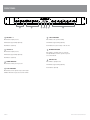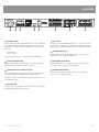
1
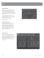
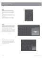
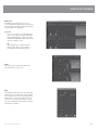
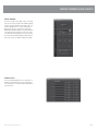
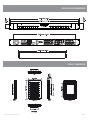
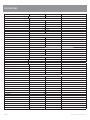
AV REVOLUTION
QUICK START MANUAL
intuitive
simple
Finally,
Fi
ll someone iis
thinking of you.
SERIES DSP
IMPORTANT SAFETY INFORMATION
1.
Save the carton and packing material even if the equipment has
arrived in good condition. Should you ever need to ship the unit, use
only the original factory packing.
2.
Read all documentation before operating your equipment. Retain
all documentation for future reference.
3.
Follow all instructions printed on unit chassis for proper operation.
4.
Do not spill water or other liquids into or on the unit, or operate
the unit while standing in liquid.
5.
Make sure power outlets conform to the power requirements listed
on the back of the unit.
6.
Do not use the unit if the electrical power cord is frayed or broken.
The power supply cords should be routed so that they are not likely
to be walked on or pinched by items placed upon or against them,
paying particular attention to cords and plugs, convenience
receptacles, and the point where they exit from the appliance.
7.
8.
9.
Always operate the unit with the AC ground wire connected to the
electrical system ground. Precautions should be taken so that the
means of grounding of a piece of equipment is not defeated.
Mains voltage must be correct and the same as that printed on the
rear of the unit. Damage caused by connection to improper AC voltage
is not covered by any warranty.
Have gain controls on amplifiers turned down during power-up
to prevent speaker damage if there are high signal levels at the inputs.
10 Power down and disconnect units from mains voltage before making
connections.
13. Do not block fan intake or exhaust ports. Do not operate equipment
on a surface or in an environment which may impede the normal flow
of air around the unit, such as a bed, rug, weathersheet, carpet,
or completely enclosed rack. If the unit is used in an extremely dusty
or smoky environment, the unit should be periodically “blown free”
of foreign matter.
14. Do not remove the cover. Removing the cover will expose you
to potentially dangerous voltages. There are no user serviceable
parts inside.
15. Do not drive the inputs with a signal level greater than that required
to drive equipment to full output.
16. Do not connect the inputs / outputs of amplifiers or consoles to any
other voltage source, such as a battery, mains source, or power supply,
regardless of whether the amplifier or console is turned on or off.
17. Do not run the output of any amplifier channel back into another
channel’s input. Do not parallel- or series-connect an amplifier output
with any other amplifier output. Australian Monitor Inc is not
responsible for damage to loudspeakers for any reason.
18. Do not ground any “hot” terminal. Never connect a “hot” output
to ground or to another “hot” output!”
19. Non-use periods. The power cord of equipment should be unplugged
from the outlet when left unused for a long period of time.
20. Service Information Equipment should be serviced by qualified service
personnel when:
A. The power supply cord or the plug has been damaged.
B. Objects have fallen, or liquid has been spilled into the equipment
11. Never hold a power switch in the “ON” position if it won’t stay
there itself!
C. The equipment has been exposed to rain
12. Do not use the unit near stoves, heat registers, radiators, or other heat
producing devices.
D. The equipment does not appear to operate normally, or exhibits a
marked change in performance
E. The equipment has been dropped, or the enclosure damaged.
THIS SAFETY INFORMATION IS OF A GENERAL NATURE AND MAY BE SUPERSEDED BY INSTRUCTIONS CONTAINED WITHIN THIS MANUAL
INTRODUCTION AND CONTENTS
The AV Revolution is packed with processing power for applications ranging
from lecture theatres and boardrooms to room combining. With options
including CobraNet cards and the Revolution remote wall panels, the AV
Revolution is a powerful system for both signal processing and source routing.
BOX CONTENTS
Av Revolution
Software CD
Quick Start Guide
INTRODUCTION
1
FRONT PANEL
2
REAR PANEL
3
SETUP
4
ADVANCED SETTINGS/AUDIO SETUP
5
ICON-CP CONTROL PANELS/PANEL SETUP
8
MASTER OVERRIDE/ GLOBAL PRESETS
9
CONTROL PANEL OPTIONS
10
DIMENSIONS
11
SPECIFICATIONS
12
AUS, EUR, USA
Copyright 25th May 2009
CAUTION
This symbol is intended to alert the user to the presence of uninsulated
“dangerous voltage” within the products enclosure that may be of sufficient
magnitude to constitute a risk of electric shock to persons.
RISK OF ELECTRIC SHOCK
DO NOT OPEN
CAUTION: TO REDUCE THE RISK OF ELECTRIC SHOCK,
DO NOT REMOVE COVER (OR BACK),
NO USER SERVICEABLE PARTS INSIDE,
REFER SERVICING TO QUALIFIED SERVICE PERSONNEL.
This symbol is intended to alert the user to the presence of important
operational and maintenance (servicing) instructions in the literature
accompanying the appliance.
Caution:
WARNING!
To prevent electric shock do not use this (polarised) plug with an extension
cord, receptacle or other outlet unless the blades can be fully inserted to
prevent blade exposure. To prevent electric shock, match wide blade of
plug to wide slot, fully insert.
TO REDUCE THE RISK OF FIRE OR ELECTRIC SHOCK
DO NOT EXPOSE THIS EQUIPMENT TO RAIN OR MOISTURE.
AV Revolution Quickstart Manual
PAGE 1
FRONT PANEL
1
1 MIC/LINE 1-4
2
3
4
5
6
7
5 STATUS INDICATOR
Blue indicates signal presence
Blue indicates the system is running
Pink indicates approaching signal clip
Pink indicates approaching signal clip
Red indicates signal clip
Red indicates the system is busy or has an error
2 STEREO 1-6
Blue indicates signal presence
Pink indicates approaching signal clip
6 NETWORK INDICATOR
Blue indicates a network device is connected.
The light will flash each time a packet is passed
across this network
Red indicates signal clip
7 ZONE OUTPUTS
3 POWER INDICATOR
Blue indicates mains power is present
4 RS485 INDICATOR
Blue indicates signal presence
Pink indicates approaching signal clip
Red indicates signal clip
Blue indicates remote panels are present, the light
will flash when data is passed across this network
PAGE 2
AV Revolution Quickstart Manual
REAR PANEL
1
2
3
4
5
1 IEC MAINS SOCKET
This is a standard 3-pin IEC socket (IEC3020-C14). It accepts a standard IEC
mains cable, provided. The fuse draw contains the mains fuse and a spare.
The mains fuse is a time lag (slow blow) HRC 20mm x 5mm fuse, the fuse
ratings are:
230V : 0.6A S/B
115V : 1.2A S/B
The power supply is universal so it will accept voltages from 90-264V.
2 OPTIONAL COBRANET CARD
Optional module available to enable Cobranet connectivity. This card will
parallel all inputs and outputs to be available on Cobranet.
3 OVERRIDE AND PRESET CONTACT CLOSURES
Pins 1-8 are trigger pins for the global presets. When any one of these pins
are momentarily joined to the COM pin that preset will be triggered.
6
7
8
5 RS485 PORTS
The RS485 ports allow the ICON-CP wall panels to be connected to the unit.
All wall panels use standard pin to pin wiring, using a straight through CAT5
cable is suggested to keep the RS485 line twisted for optimal noise rejection
6 BALANCED ZONE OUTPUTS
Balanced outputs for each zone are supplied on Weco connectors for easy
termination. These are a standard 5.08mm pitch.
7 UNBALANCED STEREO INPUTS
Unbalanced RCA connections are supplied for all stereo inputs. They are in
stereo pairs as the unit supports stereo right through.
8 BALANCED MIC/LINE INPUTS
Mic/Line inputs are supplied on WECO connectors for easy termination.
These are also a standard 5.08mm pitch.
Pin O/Ride is a trigger for the external Master Override function. This can be
set up within the software.
4 ETHERNET PORT
The Ethernet port is a standard RJ45 port which allows the user control with
the supplied GUI or a third party control system.
AV Revolution Quickstart Manual
PAGE 3
SETUP
NETWORK CONNECTION:
When the AV Revolution software is run for the first time
a default connection page is launched. By clicking
File > Settings it is possible to make this page not
appear and have the software simply connect to the
last known good connection. This allows the installer to
have the software configured and connect automatically
as the PC starts up.
The initial connection page also allows the user to
update firmware and change the IP address within the
AV Revolution hardware. This can all be done from the
Setup drop menu within the title bar.
All AV Revolution units have a default IP
of 192.168.178.178.
Connection For the First Time:
It is suggested that when connecting to the
AV Revolution for the first time that a crossover cable
is used straight between the unit and your PC. You
will then need to change your network adapter to
have an IP of 192.168.178.170 with a subnet of
255.255.255.0. Then all you will need to do is open
the AV Rev software and connect. Once you have
connected for the first time you can set the units
IP address or change it to DHCP.
ZONE CONTROL PAGE:
The main page of the AV revolution software allows
the user to adjust all routing for a particular zone.
In terms of DSP the zone routing page is after the
input source processing but before the zone’s output
processing. All inputs within the Revolution range are
available on all outputs. This page gives the user access
to adjust basic functions such as volume, panning
and mute controls.
PAGE 4
AV Revolution Quickstart Manual
ADVANCED SETTINGS/ AUDIO SETUP
ADVANCED MODE:
In the bottom right hand corner of the AV Revolution
software there is an “Advanced” button. The features
allow the contractor to adjust DSP processing, min and
max volumes and other advanced features. This section
of the software can be password protected against
inappropriate access. To set a new password click
“Settings > Set Password”.
Out of the box the AV Rev does not have a password
set. A password can be added by simply typing it into
the new password box and a pop up will inform you
that the change was successful. To remove a password
simply type in the “Old password” and then leave the
new password box blank, a prompt should appear
telling you that the password has been removed.
Advanced Mode Set Up:
At the base of the advanced mode screen, there are
four buttons added to the GUI. These allow set up of
functions relating to the Audio Setup, Control Panels,
Master Override and Presets.
AUDIO SETUP
The Audio Setup page allows the user to control all DSP
functions of each input and output signal. The page
also allows the user to see the signal flow from input
to output. Within this screen there are small signal
indicators for each input and output. This page makes a
great trouble shooting guide to see signal entering and
leaving the DSP functions.
AV Revolution Quickstart Manual
PAGE 5
AUDIO SETUP CONTINUED
Inputs
Each Mic/Line input can be configured as either
Microphone level or Line level. The user has options
such as polarity, analog gain sensitivity and digital trim.
Each Mic/Line input also supports full +48V phantom
power.
The Analog gain steps are gain adjustments in the
Analog domain where as the fader represents control of
the DSP chip.
The stereo inputs follow most of the same functions
that relate to line level inputs on the mic/line input.
Input EQ
Each input has comprehensive EQ functions: high and
low pass filters, high and low shelf and two parametric
filters. Each EQ can be adjusted in either Q or BW. All
processing is represented on the EQ frequency response
graph on the right hand side of that window.
You can save processing preset files for each block from
the EQ onwards. This allows a user to have some preset
EQ files such as “Gooseneck Microphone” or “Lapel EQ”.
Dynamics
The dynamics page allows the user to adjust a Noise
gate for each input and also a Compressor or AGC
for each input. Every block that contains two or more
processing options has an overall “bypass” in red and a
per function “bypass” in blue.
PAGE 6
AV Revolution Quickstart Manual
AUDIO SETUP CONTINUED
EQ/Crossover
The EQ/Crossover block allows you to set up a
crossover and EQ the outputs. All stereo functions have
a stereo link button. This will copy all functions from the
left to the right in stereo applications.
Crossover
The crossover section of each output allows the
user to set up a high pass, low pass and all pass
filter. Each high and low pass filter can be either
Butterworth, Linkwitz Riley or Bessel and can have
slopes up to 48dB per octave.
EQ
Each output also offers comprehensive EQ
functions. These allow a user to configure a
low and high shelf and 4 parametric filters.
Limiter
Each output features a fully optioned limiter with
stereo link function on stereo zones.
Delay
Each output has a delay for both the left and the right
channel. It has coarse and also fine control for dialing
in precise delays. The user can also simply type in the
required distance or time. At the bottom of the delay
section a user can also adjust temperature for even
more precise adjustment of delays and also switch the
measurements to imperial.
AV Revolution Quickstart Manual
PAGE 7
ICON-CP CONTROL PANELS/PANEL SET UP
ICON-CP CONTROL PANELS:
The control panel screen allows the user to set up all
control panels included in their system. Each remote
panel can be renamed for easy identification.
Once a name is given to a panel the user can specify its
type; options are 6 Volume, 6 buttons + volume
or 8 buttons.
PANEL SET UP:
From the “Configure” screen the user can set up the
zone to be controlled and what parameter the control
panel affects.
PAGE 8
AV Revolution Quickstart Manual
MASTER OVERRIDE/GLOBAL PRESETS
MASTER OVERRIDE:
The master override screen allows a user to set up all
aspects of the master override. This would be typically
used for emergency situations. The trigger source can
be either signal presence or closed contact. Once a
trigger source has been selected you can have the
Master Override “Mute all Inputs” and “Route Mic/Line
4 to all”. Both of these functions can be active at the
same time. When “Route Mic/Line 4 to all” is selected
the controls for that channel disappear from the front
page so the end user is unable to adjust the settings.
GLOBAL PRESETS:
The presets window allows the user to define up to 8
global presets. From this page you can recall presets
for set up and also store current system information to
a specific preset.
AV Revolution Quickstart Manual
PAGE 9
CONTROL PANEL OPTIONS
1
2
4
8
16
32
64
128
SW1 Address
SW2 Func
A
B
C
D
ICON-CP CONTROL PANEL
The Revolution series control panels (ICON-CP) have two banks of DIP switches
on the rear of the control panel. The first bank of switches labeled SW1 allows
the user to address the panel for RS485 communications. The second bank of
switches allows the user to set up the LED functions for the remote panel.
The ICON-CP control panels do not hold any project data so if a panel was to fail
or be broken it could simply be swapped out with a unit set to the same address.
All control panels are constantly polling the RS485 network for status. This
will allow the user to update settings via 3rd party, other control panels or the
software GUI and have all panels constantly up to date.
SW1:
Each RS485 port on the Revolution series allows you to run up to 20 control
panels to a maximum distance of 500 metres. With each unit featuring two
RS485 ports, this allows the AV Revolution to run up to 40 ICON-CP’s on two
separate 500m runs. The 500m limitation of the control panels is due to power
loss over distance and not RS485 limitations meaning if lengths longer than
500m are required you need to inject power locally for greater distances.
RS485 addresses 1-240 are allowed. With any other address the unit will blink
its error LED’s.
SW2
A: ON = LED Brightness varies based on ambient light, OFF = Fixed Brightness
B: ON = Low Brightness (if switch A is on fixed brightnes mode), OFF = Normal
Brightness
C: Unused on Revolution series
D: Unused on Revolution series
PAGE 10
AV Revolution Quickstart Manual
AV REVOLUTION DIMENSIONS
ICON-CP DIMENSIONS
AV Revolution Quickstart Manual
PAGE 11
SPECIFICATIONS
Parameter
Specification Unit
Conditions
Analog I/O
Balanced Mic Input
Impedance
Phantom Power
Gain / Max Input
Euroblock Connectors
2 K Ohm
48 V
Selectable per input
Gain Max Input
6 dB
6 dBu
24 dB -12 dBu
42 dB -30 dBu
60 dB -48 dBu
Balanced Line Input
Impedance
Gain / Max Input
Euroblock Connectors
5 K Ohm
Gain Max Input
-12 dB 24 dBu
+6 dB 6 dBu
Unbalanced RCA Input
RCA Connectors
Impedance
15 K Ohm
Maximum Input
6.2 dBu
Balanced Outputs
Euroblock Connectors
Impedance
50 Ohm
Maximum Output
24 dBu
System
Frequency Response
THD + N
Dynamic Range
Sample Rate
Latency
Processor
Processing Power
20 – 20000 Hz
0.003 %
From Input to Output (1KHz +4dBu)
108 dB
48 kHz
2.1 ms
Analog to Analog
2 x Analog Devices Sharc DSP (ADSP-21375) 32/40 bit floating point
2 x 1596 MFLOPS
Communications
Ethernet
Icon Control Panel RS485
100 Base T
500 m
20
Max cable length per port without external power
Max number of remote panels per run
240 Total using external power
Hardware
Net Weight
Size (w x d x h)
Chasis Style
Voltage
Power Consumption
Compliance
4.15 kg
482 x 330 x 44 mm
1 RU
90 – 264 VAC
<30 VA
UL
CE
CTICK
PAGE 12
AV Revolution Quickstart Manual
AUSTRALIA AND NEW ZEALAND
www.australianmonitor.com.au
SYDNEY
MELBOURNE
ADELAIDE
AUCKLAND
(NSW SALES)
(VIC & TAS SALES)
(SA & NT SALES)
(NZ SALES)
1 Clyde Street
Silverwater
NSW 2128
Private Bag 149
Silverwater NSW 1811
Phone: (02) 9647 1411
Fax: (02) 9648 3698
Email:
[email protected]
22/277
Middleborough Road
Box Hill VIC 3128
PO Box 151 Blackburn
South VIC 3130
Phone: (03) 9890 7477
Fax: (03) 9890 7977
Email:
[email protected]
31 Walsh Street
Thebarton
SA 5031
PO Box 157
Hindmarsh SA 5007
Phone: (08) 8352 4444
Fax: (08) 8352 4488
Email:
[email protected]
9C Piermark Drive
Albany 0752
New Zealand
PO Box 300-512
Albany 0752
Phone: (09) 415 9426
Fax: (09) 415 9864
Email:
[email protected]
CANBERRA
BRISBANE
PERTH
(ACT SALES)
(QLD SALES)
(WA SALES)
1st Floor,
Campion Street
Deakin ACT 2600
PO Box 109
Deakin West ACT 2600
Phone: (02) 6260 4544
Fax: (02) 6260 4744
Email: gordon.anderson@
hillssvl.com.au
42 Commercial Road
Fortitude Valley
QLD 4006
PO Box 2578 Fortitude
Valley BC QLD 4006
Phone: (07) 3852 1312
Fax: (07) 3252 1237
Email:
[email protected]
3/11 Howe Street
Osborne Park WA 6017
PO Box 1281
Osborne Park BC
WA 6916
Phone: (08) 9204 0200
Fax: (08) 9244 3783
Email:
[email protected]
EUROPE / ASIA / MIDDLE EAST
www.australianmonitor.com.au
INTERNATIONAL SALES
1 Clyde Street Silverwater NSW 2128 Australia
Private Bag 149 Silverwater NSW 1811
Phone: + 61 2 9647 1411
Fax: + 61 2 9748 2537
Email: [email protected]
A division of