1
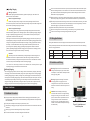
Step 1: Selecting an installation location.
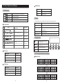
① External temperature sampling interface connection
Avoid installing solar charge controller in a place where there is direct sunlight, high temperature
or easy water inflow. Ensure the surrounding area of the solar charge controller is well ventilated.
② Battery voltage sampling line connection
Step 2:
③ Communication cable connection
First place installation guide plate at proper position, then use pen and mark on installation
location, drill four installation holes at marked places of suitable size, and fixe with screw.
④ Connect power line
Warning: Risk of electric shock! We strongly recommend access insurance or circuit breaker at
photovoltaic array end, load end and battery end, to prevent electric shock from occurring during
wiring or misoperation. Before wiring, ensure that insurance or circuit breaker is disconnected.
Step 3: Fix the solar charge controller.
On the installation surface, use a pen to mark the positions of four mounting holes, and then move
away solar charge controller. Drill four size-suitable mounting holes at four marked positions, and
fix screws in advance, align fixing holes of solar charge controller to on the four fixed screws, and
then hang it up.
Warning: High pressure danger! Photovoltaic array may generate very high open circuit voltage.
Before wire connection, disconnect the breaker or insurance. Be careful in the process of wiring.
Warning: Risk of explosion. Short circuit of battery positive and negative terminals and wires
connected to them will cause fire or explosion. Please be careful during operation.
Please connect battery first, then connect load, and finally connect the solar panel, please follow
the connection mode of "+" first and then "-".
⑤ Power On
Tip: ML series solar charge controller only starts the solar charge controller via wiring at the
battery end, but ML - LI can start the solar charge controller via power of PV array,. This applies
to starting the solar charge controller and activating lithium battery when lithium battery BMS is
in the protection state and cannot export electricity externally.
When all the power line connections are firm and reliable, recheck whether the wiring is correct,
and whether positive and negative ends are connected reversely. After confirmation, connect
battery fuse or circuit breaker, observe whether LED indicator is lit, and whether LCD screen
displays content. If there is no display, disconnect the fuse or circuit breaker immediately and
recheck whether the circuit connection is correct.
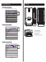
Figure 2-2 Fix the solar charge controller
Step 4: Wiring
If battery is powered on normally, connect the solar panel. If solar charge controller charging
indicators are on normally or flashing, start battery charging.
Remove the two screws on the solar charge controller panel, and then start wiring. For installation
security, we recommend the following wiring sequence. However, wiring without following this
order will not damage the solar charge controller.
When battery and photovoltaic is well connected, then connect load fuse or circuit breaker. At
this time, you can use manual mode to test whether the load On and Off is normal. See load
working mode and operation.
Temp Sense
Warning: When the solar charge controller is under normal charging state, disconnecting
battery connection will affect solar charge controller DC load. In a severe case, the load can be
damaged.
Warning: Within 10 minutes after solar charge controller charging stops, battery reverse polarity
operation may damage internal components of the solar charge controller.
7
!
5
3
6
4
2
1
Attention:
1) Battery insurance installation site should be as close as possible to the battery end.
Recommended installation distance shall be no more than 150 mm.
2) When solar charge controller is not connected to a remote temperature sensor, battery
temperature is a fixed value of 25 ℃.
3) If the inverter is connected in the system, please connect inverter directly with battery, and do
not connect solar charge controller with the load end.
⑥ Close wiring cover
Figure 2-3 Wiring
09
When all wirings of the system are well connected, close the wiring cover and screw screws tight.
10