1
RENESAS TECHNICAL UPDATE TN-RX*-A048A/E
Date: January 15, 2013
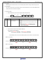
Bit
Symbol
Bit name
Description
R/W
b7-0
TMOCNTL
Timeout internal counter
Timeout internal counter low-order
W
*1
*1 : Value in timeout internal counter cannot be read. When value is read, the read value is FFh.
Bit
b7-0
Symbol
TMOCNTU
Bit name
Description
Timeout internal counter
R/W
Timeout internal counter high-order
*1
W
*2
*1 : With TMOS=1 (Short mode), b7-b4 are reserved bits. They are writable, however value written is disabled.
*2 : Value in timeout internal counter cannot be read. When value is read, the read value is FFh.
Timeout internal counter ( TMOCNTL/TMOCNTU )
is initialized (00h) after a reset, while ICCR1.IICRST=1 or
ICFER.TMOE=1 and PCLK/1 is selected with ICMR1.CKS[2:0]=000b setting, and when counter clear conditions specified by
TMOH/TMOL of ICMR2 (SCL rising edge/falling edge detection) are satisfied.
TMOCNTL register and TMOCNTU register comprise a single 16-bit register so they can be accessed together by 16-bit
transfer instruction. In case of 16-bit access, please access to the address indicated in the table “Register Allocation for 16-Bit
Access” below.
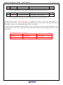
Table. Register Allocation for 16-Bit Access
Address
Upper 8 Bits
Lower 8 Bits
0008 830Ah
RIIC0.TMOCNTU
RIIC0.TMOCNTL
0008 832Ah
RIIC1.TMOCNTU
RIIC1.TMOCNTL
Page 3 of 10