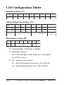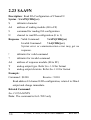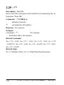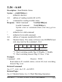
1
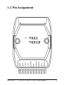
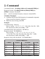
I-7021/21P, I-7022, I-7024 User Manual Warranty All products manufactured by ICP DAS are warranted against defective materials for a period of one year from the date of delivery to the original purchaser. Warning ICP DAS assume no liability for damages consequent to the use of this product. ICP DAS reserves the right to change this manual at any time without notice. The information furnished by ICP DAS is believed to be accurate and reliable. However, no responsibility is assumed by ICP DAS for its use, nor for any infringements of patents or other rights of third parties resulting from its use. Copyright Copyright 1999 by ICP DAS. All rights are reserved. Trademark The names used for identification only maybe registered trademarks of their respective companies. Date:2001-05 Rev:B1.2 I-7021, I-7022, I-7024 User Manual 1 Table of Contents 1. Introduction.....................................................6 1.1 More Information.......................................6 1.2 Pin Assignment ..........................................7 1.3 Specifications...........................................10 1.4 Block Diagram .........................................12 1.5 Jumper Setting .........................................14 1.6 Wire Connection ......................................14 1.7 Quick Start ...............................................15 1.8 Default Setting .........................................15 1.9 Calibration ...............................................16 1.10 Configuration Tables ..............................22 2. Command.......................................................26 2.1 %AANNTTCCFF ....................................29 2.2 $AA2........................................................30 2.3 $AA5........................................................31 2.4 $AAF .......................................................32 2.5 $AAM ......................................................33 2.6 ~AAO(Data) ............................................34 2.7 #AA(Data) ...............................................35 2.8 $AA0........................................................37 2.9 $AA1........................................................38 2.10 $AA3VV ................................................39 2 I-7021, I-7022, I-7024 User Manual Rev:B1.2 2.11 $AA4 ......................................................40 2.12 $AA6......................................................41 2.13 $AA7......................................................42 2.14 $AA8......................................................43 2.15 #AAN(Data) ..........................................45 2.16 $AA0N ...................................................47 2.17 $AA1N ...................................................48 2.18 $AA3NVV .............................................49 2.19 $AA4N ...................................................50 2.20 $AA6N ...................................................51 2.21.1 $AA7N ................................................52 2.21.2 $AA7N ................................................53 2.22 $AA8N ...................................................54 2.23 $AA9N ...................................................56 2.24 $AA9NTS ..............................................57 2.25 ~** .........................................................58 2.26 ~AA0 .....................................................59 2.27 ~AA1 .....................................................60 2.28 ~AA2 .....................................................61 2.29 ~AA3EVV .............................................62 2.30 ~AA4 .....................................................64 2.31 ~AA4N...................................................65 2.32 ~AA5 .....................................................66 2.33 ~AA5N...................................................67 Rev:B1.2 I-7021, I-7022, I-7024 User Manual 3 3. Application Note............................................68 3.1 INIT* pin Operation ................................68 3.2 Module Status ..........................................68 3.3 Dual Watchdog Operation ........................69 3.4 Reset Status..............................................69 3.5 Analog Output..........................................69 3.6 Slew Rate Control....................................70 3.7 Current Readback.....................................71 4 I-7021, I-7022, I-7024 User Manual Rev:B1.2 Rev:B1.2 I-7021, I-7022, I-7024 User Manual 5 1. Introduction I-7000 is a family of network data acquisition and control modules. They provide analog-to-digital, digital-to-analog, digital input/output, timer/counter and other functions. These modules can be remote controlled by a set of commands. The basic features of I-7021, I-7021P, I-7022 and I-7024 are given as following : z 3000 VDC isolated analog output. z Programmable PowerOn Value of analog output. z Programmable slew rate. Software calibration. The I-7021 is an analog output module with 12-bit resolution and current readback function. The I-7021P is similiar with I7021 but with 16-bit resolution. The I-7022 is the dual channel version of I-7021. The I-7024 is a 4-channel analog output module, and supports bipolar voltage output. z 1.1 More Information Refer to “I-7000 Bus Converter User Manual” chapter 1 for more information as following: 1.1 I-7000 Overview 1.2 I-7000 Related Documentation 1.3 I-7000 Command Features 1.4 I-7000 System Network Configuration 1.5 I-7000 Dimension 6 I-7021, I-7022, I-7024 User Manual Rev:B1.2 1.2 Pin Assignment Rev:B1.2 I-7021, I-7022, I-7024 User Manual 7 8 I-7021, I-7022, I-7024 User Manual Rev:B1.2 Rev:B1.2 I-7021, I-7022, I-7024 User Manual 9 1.3 Specifications I-7021 Analog Output Output Channel : 1 Output Type : mA, V Accuracy : ±0.1% of FSR Resolution : ±0.02% of FSR Readback Accuracy : ±1% of FSR Zero Drift : Voltage output : ±30µV/°C Current output : ±0.2µA/°C Span Temperature Coefficient : ±25ppm/°C Programmable Output Slope : 0.125 to 1024 mA/Second 0.0625 to 512 V/Second Voltage Output : 10mA max. Current Load Resistance : Internal power : 500 ohms External 24V : 1050 ohms Isolation : 3000VDC Power Supply Input : +10 to +30VDC Consumption : 1.8W 10 I-7021P Analog Output Output Channel : 1 Output Type : mA, V Accuracy : ±0.02% of FSR Resolution : ±0.002% of FSR Readback Accuracy : ±1% of FSR Zero Drift : Voltage output : ±10µV/°C Current output : ±0.2µA/°C Span Temperature Coefficient : ±5ppm/°C Programmable Output Slope : 0.125 to 1024 mA/Second 0.0625 to 512 V/Second Voltage Output : 10mA max. Current Load Resistance : Internal power : 500 ohms External 24V : 1050 ohms Isolation : 3000VDC Power Supply Input : +10 to +30VDC Consumption : 1.8W I-7021, I-7022, I-7024 User Manual Rev:B1.2 I-7022 I-7024 Analog Output Analog Output Output Channel : 2 Output Channel : 4 Output Type : mA, V Output Type : mA, V Accuracy : ±0.1% of FSR Accuracy : ±0.1% of FSR Resolution : ±0.02% of FSR Resolution : ±0.02% of FSR Readback Accuracy : ±1% of Zero Drift : FSR Voltage output : ±30µV/°C Zero Drift : Current output : ±0.2µA/°C Voltage output : ±30µV/°C Span Temperature Coefficient : Current output : ±0.2µA/°C ±20ppm/°C Span Temperature Coefficient : Programmable Output Slope : ±25ppm/°C 0.125 to 2048 mA/Second Programmable Output Slope : 0.0625 to 1024 V/Second 0.125 to 1024 mA/Second Voltage Output : 5mA max. 0.0625 to 512 V/Second Current Load Resistance : Voltage Output : 10mA max. External 24V : 1050 ohms Current Load Resistance : Isolation : 3000VDC Internal power : 500 ohms Power Supply External 24V : 1050 ohms Input : +10 to +30VDC Isolation : 3000VDC Consumption : 2.3W Channel-to-channel isolation Power Supply Input : +10 to +30VDC Consumption : 3.0W Rev:B1.2 I-7021, I-7022, I-7024 User Manual 11 1.4 Block Diagram 12 I-7021, I-7022, I-7024 User Manual Rev:B1.2 Rev:B1.2 I-7021, I-7022, I-7024 User Manual 13 1.5 Jumper Setting Jumper select the current output power supply of I-7021/21P : 1. Select internal power of module : default setting, may drive load up to 500 ohms. 2. Select external power of module : may drive larger load. with 24V power, may drive 1050 ohms. Jumper select the current output power supply of I-7022 : 1. JP1 for channel 0 setting, and JP2 for channel 1 setting. 2. Select internal power : 500 ohms load max. 3. External power : 1050 ohms with external +24VDC power. 1.6 Wire Connection I-7021/21P/22 Voltage Output Wire Connection 14 I-7021, I-7022, I-7024 User Manual Rev:B1.2 I-7021/21P/22 Current Output Wire Connection I-7024 Voltage Output Wire Connection I-7024 Current Output Wire Connection 1.7 Quick Start Refer to “I-7000 Bus Converter User Manual” and “Getting Start” for more detail. 1.8 Default Setting Default setting for I-7021, I-7021P, I-7022 and I-7024 : z Address : 01 z Analog Output Type : 0 to +10V z Baudrate : 9600 bps z Checksum disable, change immediate, engineer unit format z I-7021, I-7021P, I-7022 jumper setting : internal power. Rev:B1.2 I-7021, I-7022, I-7024 User Manual 15 1.9 Calibration Don’t Perform Calibrate Until You Really Understand. I-7021/21P Current Output Calibration Sequence : 1 Set the jumper1 to internal power and connect mA-meter to module’s current output. If no mA-meter, you may use VoltMeter with shunt resistor(250 ohms, 0.1%), and calculate the mA by the Volt-Meter value (I = V/250). 2 3 4 5 6 7 8 9 Warm-Up for 30 minutes. Setting type to 30. (0 to 20mA) Output 4mA. Check the meter and trim the output until 4mA match by apply trim command. Preform 4mA Calibration Command. Output 20mA. Check the meter and trim the output until 20mA match by apply trim command. Perform 20mA Calibration Command. 16 -> Refer Sec.2.1. -> Refer Sec.2.7. -> Refer Sec.2.10. -> Refer Sec.2.8. -> Refer Sec.2.7. -> Refer Sec.2.10 -> Refer Sec.2.9. I-7021, I-7022, I-7024 User Manual Rev:B1.2 I-7021/21P Voltage Output Calibration Sequence : 1 Connect volt-meter to module’s voltage output. Short the current output pin for the readback requriement. 2 3 4 5 6 Warm-Up for 30 minutes. Setting type to 32. (0 to 10V) Output 10V. Check the meter and trim the output until 10V match by apply trim command. Perform 10V Calibration Command. Rev:B1.2 -> Refer Sec.2.1. -> Refer Sec.2.7. -> Refer Sec.2.10. -> Refer Sec.2.13. I-7021, I-7022, I-7024 User Manual 17 I-7022 Current Output Calibration Sequence : 1 Set the jumper to internal power and connect mA-meter to module’s current output channel 0. If no mA-meter, you may use Volt-Meter with shunt resistor(250 ohms, 0.1%), and calculate the mA by the Volt-Meter value (I = V/250). 2 3 4 5 Warm-Up for 30 minutes. Setting output type to 0. (0 to 20mA) Output 4mA. Check the meter and trim the output until 4mA match by apply trim command. 6 Preform 4mA Calibration Command. 7 Output 20mA. 8 Check the meter and trim the output until 20mA match by apply trim command. 9 Perform 20mA Calibration Command. 10 Repeat step 1 to 9 for channel 1. 18 -> Refer Sec.2.24. -> Refer Sec.2.15. -> Refer Sec.2.18. -> Refer Sec.2.16. -> Refer Sec.2.15. -> Refer Sec.2.18. -> Refer Sec.2.17. I-7021, I-7022, I-7024 User Manual Rev:B1.2 I-7022 Voltage Output Calibration Sequence : 1 Connect volt-meter to module’s voltage output channel 0. Short the current output pin for the readback requriement. 2 3 4 5 6 7 Warm-Up for 30 minutes. Setting Output type to 2. (0 to 10V) Output 10V. Check the meter and trim the output until 10V match by apply trim command. Perform 10V Calibration Command. Repeat step 1 to 6 for channel 1. Rev:B1.2 -> Refer Sec.2.24. -> Refer Sec.2.15. -> Refer Sec.2.18. -> Refer Sec.2.21. I-7021, I-7022, I-7024 User Manual 19 I-7024 Current Output Calibration Sequence : 1 Connect meter and external power source to module’s current output channel 0. 2 3 4 5 Warm-Up for 30 minutes. Setting type to 30. (0 to 20mA) Output 0mA. Check the meter and trim the output until 0mA match by apply trim command. 6 Preform 0mA Calibration Command. 7 Output 20mA. 8 Check the meter and trim the output until 20mA match by apply trim command. 9 Perform 20mA Calibration Command. 10 Repeat 1 to 9 for channel 1, 2 and 3. 20 -> Refer Sec.2.1. -> Refer Sec.2.15. -> Refer Sec.2.18. -> Refer Sec.2.16. -> Refer Sec.2.15. -> Refer Sec.2.18. -> Refer Sec.2.17. I-7021, I-7022, I-7024 User Manual Rev:B1.2 I-7024 Current Output Calibration Sequence : 1 Connect meter to module’s voltage output channel 0. 2 3 4 5 Warm-Up for 30 minutes. Setting type to 33. (-10 to 10V) Output -10V. Check the meter and trim the output until -10V match by apply trim command. 6 Perform -10V Calibration Command. 7 Output 10V. 8 Check the meter and trim the output until 10V match by apply trim command. 9 Perform 10V Calibration Command. 10 Repeat 1 to 9 for channel 1, 2 and 3. Rev:B1.2 -> Refer Sec.2.1. -> Refer Sec.2.15. -> Refer Sec.2.18. -> Refer Sec.2.16. -> Ref Sec.2.15. -> Ref Sec.2.18. -> Ref Sec.2.17. I-7021, I-7022, I-7024 User Manual 21 1.10 Configuration Tables Baudrate Setting (CC) C ode 03 04 05 06 07 08 09 Baudrate 1200 2400 4800 9600 19200 38400 0A 57600 115200 Analog Output Type Setting (TT) Type Code 30 31 32 33 34 35 3F Min. Output 0 mA 4 mV 0V - 10 V 0V -5 V - Max. Output 20 mA 20 mA +10 V +10 V +5 V +5 V - Note For I- 7021/21P/24 For I- 7024 only For I- 7022 only Data Format Setting (FF) 7 6 0 *1 5 4 3 *2 2 1 0 *3 *1 :Checksum Bit : 0=Disable, 1=Enable *2 :Slew Rate Control : for I-7021/21P and I-7024, Refer Sec.3.6 for detail for I-7022, set to 0 *3 :00 = Engineer Unit Format 01 = Percent of Span Format (For I-7021/21P/22) 10 = Hexadecimal Format (For I-7021/21P/22) 22 I-7021, I-7022, I-7024 User Manual Rev:B1.2 Sle w Rate for I-7021/21P and I-7024 V/Se cond mA/Se cond 0000 Immediate V/Se cond mA/Se cond 1000 8.0 16.0 0001 0.0625 0.125 1001 16.0 32.0 0 0 10 0.125 0.25 1010 32.0 64.0 0011 0.25 0.5 1011 64.0 12 8 . 0 0 10 0 0.5 1.0 1100 128.0 256.0 0101 1.0 2.0 1101 256.0 512.0 0110 2.0 4.0 1110 512.0 10 2 4 . 0 0111 4.0 8.0 1111 1024.0 2048.0 Note The config 1111 is for I- 7024 only Analog Output Type and Data Format for I-7021/21P Type Code 30 31 32 Output Range 0 to 20 mA 4 to 20 mA 0 to 10 V Data Format M ax. M in. Engineer Unit 20.000 00.000 % of Span +100.00 +000.00 Hexadecimal FFF 0000 Engineer Unit 20.000 04.000 % of Span +100.00 +000.00 Hexadecimal FFF 0000 Engineer Unit 10.000 00.000 % of Span +100.00 +000.00 Hexadecimal Rev:B1.2 I-7021, I-7022, I-7024 User Manual FFF 0000 23 Analog Output Type and Data Format for I-7022 Output Type 0 1 2 Output Range 0 to 20 mA 4 to 20 mA 0 to 10 V Data Format M ax. M in. Engineer Unit 20.000 00.000 % of Span +100.00 +000.00 Hexadecimal FFF 0000 Engineer Unit 20.000 04.000 % of Span +100.00 +000.00 Hexadecimal FFF 0000 Engineer Unit 10.000 00.000 % of Span +100.00 +000.00 Hexadecimal FFF 0000 Analog Output Type and Data Format for I-7024 Type Code Output Range Data Format 30 0 to 20 mA Engineer Unit +20.000 +00.000 31 4 to 20 mA Engineer Unit +20.000 +04.000 32 0 to 10 V Engineer Unit +10.000 +00.000 33 - 10 to +10 V Engineer Unit +10.000 - 10.000 34 0 to +5 V Engineer Unit +05.000 +00.000 35 - 5 to +5 V Engineer Unit +05.000 - 05.000 24 M ax. I-7021, I-7022, I-7024 User Manual M in. Rev:B1.2 DA Configuration of I-7022 Analog Output Type (T) 0 0mA to 20mA current output 1 4mA to 20mA current output 2 0V to 10V voltage output Slew Rate Control (S) 0 Immediate chang 1 0.0625V/Second or 0.125mA/Second 2 0.125V/Second or 0.25mA/Second 3 0.25V/Second or 0.5mA/Second 4 0.5V/Second or 1.0mA/Second 5 1.0V/Second or 2.0mA/Second 6 2.0V/Second or 4.0mA/Second 7 4.0V/Second or 8.0mA/Second 8 8.0V/Second or 16mA/Second 9 16V/Second or 32mA/Second A 32V/Second or 64mA/Second B 64V/Second or 128mA/Second C 128V/Second or 256mA/Second D 256V/Second or 512mA/Second E 512V/Second or 1024mA/Second Rev:B1.2 I-7021, I-7022, I-7024 User Manual 25 2. Command Command Format : (Leading)(Address)(Command)[CHK](cr) Response Format : (Leading)(Address)(Data)[CHK](cr) [CHK] 2-character checksum (cr) end-of-command character, character return(0x0D) Calculate Checksum : 1. Calculate ASCII sum of all characters of command(or response) string except the character return(cr). 2. Mask the sum of string with 0ffh. Example : Command string : $012(cr) Sum of string = ‘$’+‘0’+‘1’+‘2’ = 24h+30h+31h+32h = B7h The checksum is B7h, and [CHK] = “B7” Command string with checksum : $012B7(cr) Response string : !01300600(cr) Sum of string : ‘!’+‘0’+‘1’+‘3’+‘0’+‘0’+‘6’+‘0’+‘0’ = 21h+30h+31h+33h+30h+30h+36h+30h+30h = 1ABh The checksum is ABh, and [CHK] = “AB” Response string with checksum : !01300600AB(cr) Ge ne ral Command Se ts Command Re s pons e %AANNTTCCFF !AA De s cription Set Module Configuration Se ction Sec.2.1 $AA2 !AANNTTCCFF Read Configuration Sec.2.2 $AA5 !AAS Read Reset Status Sec.2.3 $AAF !AA(Data) Read Firmware Version Sec.2.4 $AAM !AA(Data) Read Module Name Sec.2.5 ~AAO(Data) !AA Set Module Name Sec.2.6 26 I-7021, I-7022, I-7024 User Manual Rev:B1.2 I-7021/21P Analog Output Command Se ts Command Re s pons e De s cription Se ction #AA(Data) > Output Analog Value Sec.2.7 $AA0 !AA 4mA Calibration Sec.2.8 $AA1 !AA 20mA Calibration Sec.2.9 $AA3VV !AA Trim Calibration Sec.2.10 $AA4 !AA Set PowerOn Value Sec.2.11 $AA6 !AA(Data) Last Value Readback Sec.2.12 $AA7 !AA 10V Calibration Sec.2.13 $AA8 !AA(Data) Current Readback Sec.2.14 I-7022 Analog Output Command Se ts (All command for s pe cificie d channe l N) Command Re s pons e De s cription Se ction #AAN(Data) > Output Analog Value Sec.2.15 $AA0N !AA 4mA Calibration Sec.2.16 $AA1N !AA 20mA Calibration Sec.2.17 $AA3NVV !AA Trim Calibration Sec.2.18 $AA4N !AA Set PowerOn Value Sec.2.19 $AA6N !AA(Data) Last Value Readback Sec.2.20 $AA7N !AA 10V Calibration Sec.2.21.1 $AA8N !AA(Data) Current Readback Sec.2.22 $AA9N !AATS Read DA Configuration Sec.2.23 $AA9NTS !AA Set DA Configuration Sec.2.24 Rev:B1.2 I-7021, I-7022, I-7024 User Manual 27 I-7024 Analog Output Command Se ts (All commands for s pe cificie d channe l N) Command Re s pons e De s cription Se ction #AAN(Data) > Output Analog Value Sec.2.15 $AA0N !AA 0mA/- 10V Calibration Sec.2.16 $AA1N !AA 20mA/10V Calibration Sec.2.17 $AA3NVV !AA Trim Calibration Sec.2.18 $AA4N !AA Set PowerOn Value Sec.2.19 $AA6N !AA(Data) Last Value Readback Sec.2.20 $AA7N !AA Read PowerOn Value Sec.2.21.2 $AA8N !AA(Data) Current Value Readback Sec.2.22 Hos t Watchdog Re late d Command Se ts Command Re s pons e De s cription Sect i on ~ ** No Response Host OK Sec.2.25 ~AA0 !AASS Read Module Status Sec.2.26 ~AA1 !AA Reset Module Status Sec.2.27 ~AA2 !AAVV Read Host Watchdog Timeout Value Sec.2.28 ~AA3EVV !AA Set Host Watchdog Timeout Value Sec.2.29 ~AA4 !AA(Data) Read Safe Value Sec.2.30 ~AA4N !AA(Data) Read Safe Value of Channel N Sec.2.31 ~AA5 !AA Set Safe Value Sec.2.32 ~AA5N !AA Set Safe Value of Channel Sec.2.33 N 28 I-7021, I-7022, I-7024 User Manual Rev:B1.2 2.1 %AANNTTCCFF Description : Set module Configuration Syntax : %AANNTTCCFF[CHK](cr) % delimiter character AA address of setting module (00 to FF) NN new address for setting module (00 to FF) TT new type for setting module (Ref Sec.1.10) CC new baudrate for setting module (Ref Sec.1.10) FF new data format for setting module (Ref Sec.1.10) When changing the baudrate or checksum, it is necessary to short the pin INIT* to ground. Response : Valid Command : !AA[CHK](cr) Invalid Command : ?AA[CHK](cr) Syntax error or communication error may get no response. ! delimiter for valid command ? delimiter for invalid command. While changing baudrate or checksum setting without shorting INIT* to ground, the module will return invalid command. AA address of response module (00 to FF) Example : Command : %0102300600 Receive : !02 Change address from 01 to 02, return success. Related Command : Sec.2.2 $AA2 Related Topics : Sec.1.10 Configuration Tables, Sec.3.1 INIT* pin Operation Rev:B1.2 I-7021, I-7022, I-7024 User Manual 29 2.2 $AA2 Description : Read Configuration Syntax : $AA2[CHK](cr) $ delimiter character AA address of reading module (00 to FF) 2 command for reading configuration Response : Valid Command : !AATTCCFF[CHK](cr) Invalid Command : ?AA[CHK](cr) Syntax error or communication error may get no response. ! delimiter for valid command ? delimiter for invalid command AA address of response module (00 to FF) TT type code of module (reference Sec.1.10) CC baudrate code of module (reference Sec.1.10) FF data format of module (reference Sec.1.10) Example : Command : $012 Receive : !01300600 Read configuration of module in address 01, which is an I7021 module, return analog output 0 to 20mA, baudrate 9600bps, no checksum, engineer unit format and output change immediate. Related Command : Sec.2.1 %AANNTTCCFF Related Topics : Sec.1.10 Configuration Tables, Sec3.1 INIT* pin Operation 30 I-7021, I-7022, I-7024 User Manual Rev:B1.2 2.3 $AA5 Description : Read Reset Status Command : $AA5[CHK](cr) $ delimiter character AA address of reading module (00 to FF) 5 command for reading reset status Response : Valid Command : !AAS[CHK](cr) Invalid Command : ?AA[CHK](cr) Syntax error or communication error may get no response. ! delimiter for valid command ? delimiter for invalid command AA address of response module (00 to FF) S reset status, 1 = the module is been reseted, 0 = the module is not been reseted Example : Command : $015 Receive : !011 Read address 01 reset status, return first read. Command : $015 Receive : !010 Read address 01 reset status, return no reset occurred. Related Topics : Sec3.4 Reset Status Rev:B1.2 I-7021, I-7022, I-7024 User Manual 31 2.4 $AAF Description : Read Firmware Version Syntax : $AAF[CHK](cr) $ delimiter character AA address of reading module (00 to FF) F command for reading firmware version Response : Valid Command : !AA(Data)[CHK](cr) Invalid Command : ?AA[CHK](cr) Syntax error or communication error may get no response. ! delimiter for valid command ? delimiter for invalid command AA address of response module (00 to FF) (Data) firmware version of module Example : Command : $01F Receive : !01A2.0 Read address 01 firmware version, return version A2.0. Command : $02F Receive : !01B1.1 Read address 02 firmware version, return version B1.1. 32 I-7021, I-7022, I-7024 User Manual Rev:B1.2 2.5 $AAM Description : Read Module Name Syntax : $AAM[CHK](cr) $ delimiter character AA address of reading module (00 to FF) M command for reading module name Response : Valid Command : !AA(Data)[CHK](cr) Invalid Command : ?AA[CHK](cr) Syntax error or communication error may get no response. ! delimiter for valid command ? delimiter for invalid command AA address of response module (00 to FF) (Data) Name of module Example : Command : $01M Receive : !017021 Read address 01 module name, return name 7021. Command : $03M Receive : !037021P Read address 03 module name, return name 7021P. Related Command : Sec.2.6 ~AAO(Data) Rev:B1.2 I-7021, I-7022, I-7024 User Manual 33 2.6 ~AAO(Data) Description : Set Module Name Syntax : ~AAO(Data)[CHK](cr) ~ delimiter character AA address of setting module (00 to FF) O command for setting module name (Data) new name for module, max 6 characters Response : Valid Command : !AA[CHK](cr) Invalid Command : ?AA[CHK](cr) Syntax error or communication error may get no response. ! delimiter for valid command ? delimiter for invalid command AA address of response module (00 to FF) Example : Command : ~01O7021 Receive : !01 Set address 01 module name to 7021, return success. Command : $01M Receive : !017021 Read address 01 module name, return 7021. Related Command : Sec.2.5 $AAM 34 I-7021, I-7022, I-7024 User Manual Rev:B1.2 2.7 #AA(Data) Description : Output Analog Value Syntax : #AA(Data)[CHK](cr) # delimiter character AA address of output module (00 to FF) (Data) analog output value, reference Sec.1.10 for its format. Response : Valid Command : >[CHK](cr) Out of Range : ?[CHK](cr) Ignore Command :  Syntax error or communication error may get no response. > delimiter for valid command ? delimiter while the (Data) is out of range, and the output will goto the closest value in the setting of module’s range. ! delimiter for the module’s host watchdog flag is set, and the output command will be ignored and the output is set to Safe Value. Example : Command : $012 Receive : !01300600 Read address 01 configuration, return output type 0 to 20mA, engineer unit format and output change immediate. Command : #0105.000 Receive : > Output address 01 value 5.0mA, return success. Command : #0125.000 Receive : ?01 Output address 01 value 25.0mA, return the value is out of range, and the output is set to the 20.0mA. Rev:B1.2 I-7021, I-7022, I-7024 User Manual 35 Command : $022 Receive : !02300601 Read address 02 configuration, return output type 0 to 20mA, percent of span format, output change immediate. Command : #02+050.00 Receive : > Output address 02 value 50% (=10mA), return success. Command : $032 Receive : !02300602 Read address 03 configuration, return output type 0 to 20mA, hexadecimal format, output change immediate. Command : #03800 Receive : > Output address 03 value 0x800 (=10mA), return success. Related Command : Sec.2.1 %AANNTTCCFF, Sec.2.2 $AA2 Related Topics : Sec.1.10 Configuration Tables, Sec.3.5 Analog Output Note : The command is for I-7021/21P only 36 I-7021, I-7022, I-7024 User Manual Rev:B1.2 2.8 $AA0 Description : Perform 4mA Calibration Syntax : $AA0[CHK](cr) $ delimiter character AA address of setting module (00 to FF) 0 command for performing 4mA calibration Response : Valid Command : !AA[CHK](cr) Invalid Command : ?AA[CHK](cr) Syntax error or communication error may get no response. ! delimiter for valid command ? delimiter for invalid command AA address of response module (00 to FF) Example : Command : $010 Receive : !01 Perform address 01 4mA calibration, return success. Related Command : Sec.2.9 $AA1, Sec.2.10 $AA3VV Related Topics : Sec.1.9 Calibration Note : The command is for I-7021/21P only Rev:B1.2 I-7021, I-7022, I-7024 User Manual 37 2.9 $AA1 Description : Perform 20mA Calibration Syntax : $AA1[CHK](cr) $ delimiter character AA address of setting module (00 to FF) 1 command for performing 20mA calibration Response : Valid Command : !AA[CHK](cr) Invalid Command : ?AA[CHK](cr) Syntax error or communication error may get no response. ! delimiter for valid command ? delimiter for invalid command AA address of response module (00 to FF) Example : Command : $011 Receive : !01 Perform address 01 20mA calibration, return success. Related Command : Sec.2.8 $AA0, Sec.2.10 $AA3VV Related Topics : Sec.1.9 Calibration Note : The command is for I-7021/21P only 38 I-7021, I-7022, I-7024 User Manual Rev:B1.2 2.10 $AA3VV Description : Trim Calibration Syntax : $AA3VV[CHK](cr) $ delimiter character AA address of setting module (00 to FF) 3 command for trimming calibration VV 2’s complement hexadecimal to trim the analog output value. 00 to 5F to increase 0 to 95 counts, and FF to A1 to decrease 1 to 95 counts. Each count indicates 4.88µA or 2.44mV. Response : Valid Command : !AA[CHK](cr) Invalid Command : ?AA[CHK](cr) Syntax error or communication error may get no response. ! delimiter for valid command ? delimiter for invalid command AA address of response module (00 to FF) Example : Command : $0131F Receive : !01 Trim address 01 output to increase 31 counts, return success. Related Command : Sec.2.8 $AA0, Sec.2.9 $AA1, Sec.2.13 $AA7 Related Topics : Sec.1.9 Calibration Note : The command is for I-7021/21P only Rev:B1.2 I-7021, I-7022, I-7024 User Manual 39 2.11 $AA4 Description : Set PowerOn Value Syntax : $AA4[CHK](cr) $ delimiter character AA address of setting module (00 to FF) 4 command for setting PowerOn Value. Store the current output value as PowerOn Value. Response : Valid Command : !AA[CHK](cr) Invalid Command : ?AA[CHK](cr) Syntax error or communication error may get no response. ! delimiter for valid command ? delimiter for invalid command AA address of response module (00 to FF) Example : Command : #0100.000 Receive : > Set address 01 output 0.0mA, return success. Command : $014 Receive : !01 Set address 01 PowerOn Value, return success. The module 01 will goto 0.0mA while the moudule power on. Related Command : Sec.2.7 #AA(Data) Related Topics : Sec.3.5 Analog Output Note : The command is for I-7021/21P only 40 I-7021, I-7022, I-7024 User Manual Rev:B1.2 2.12 $AA6 Description : Last Value Readback Syntax : $AA6[CHK](cr) $ delimiter character AA address of reading module (00 to FF) 6 command for reading last output command value Response : Valid Command : !AA(Data)[CHK](cr) Invalid Command : ?AA[CHK](cr) Syntax error or communication error may get no response. ! delimiter for valid command ? delimiter for invalid command AA address of response module (00 to FF) (Data) the last output command value. If no output applied to the module, the (Data) is the PowerOn Value of the module. Refer Sec.1.10 for format. Example : Command : #0110.000 Receive : !01 Set address 01 output 10.0, return success. Command : $016 Receive : !0110.000 Read address 01 last output command value, return 10.000. Related Command : Sec.2.7 #AA(Data), Sec.2.14 $AA8 Related Topics : Sec.3.7 Current Readback Note : The command is for I-7021/21P only Rev:B1.2 I-7021, I-7022, I-7024 User Manual 41 2.13 $AA7 Description : Perform 10V Calibration Syntax : $AA7[CHK](cr) $ delimiter character AA address of setting module (00 to FF) 1 command for performing 10V calibration Response : Valid Command : !AA[CHK](cr) Invalid Command : ?AA[CHK](cr) Syntax error or communication error may get no response. ! delimiter for valid command ? delimiter for invalid command AA address of response module (00 to FF) Example : Command : $017 Receive : !01 Perform address 01 10V calibration, return success. Related Command : Sec.2.10 $AA3VV Related Topics : Sec.1.9 Calibration Note : The command is for I-7021/21P only 42 I-7021, I-7022, I-7024 User Manual Rev:B1.2 2.14 $AA8 Description : Current Readback Syntax : $AA6[CHK](cr) $ delimiter character AA address of reading module (00 to FF) 8 command for current readback Response : Valid Command : !AA(Data)[CHK](cr) Invalid Command : ?AA[CHK](cr) Syntax error or communication error may get no response. ! delimiter for valid command ? delimiter for invalid command AA address of response module (00 to FF) (Data) the current output value. Refer Sec.1.9 for format. Example : Command : $012 Receive : !01320614 Read address 01 configuration, return output type 0 to 10V, 9600 bps, engineer unit format and slew rate is 1.0V/Second. Command : #0110.000 Receive : > Set address 01 output 10.0V, return success. Command : $016 Receive : !0110.000 Read address 01 last output command value, return 10.000. Command : $018 Receive : !0101.000 Read address 01 current value, return 1.0V. Command : $018 Receive : !0101.500 Read address 01 current value, return 1.5V. Rev:B1.2 I-7021, I-7022, I-7024 User Manual 43 Related Command : Sec.2.7 #AA(Data), Sec.2.12 $AA6 Related Topics : Sec.3.6 Slew Rate Control, Sec.3.7 Current Readback Note : The command is for I-7021/21P only 44 I-7021, I-7022, I-7024 User Manual Rev:B1.2 2.15 #AAN(Data) Description : Output Analog Value for Channel N Syntax : #AAN(Data)[CHK](cr) # delimiter character AA address of output module (00 to FF) N output channel (0 to 1 for I-7022, 0 to 3 for I-7024) (Data) analog output value, reference Sec.1.10 for its format. Response : Valid Command : >[CHK](cr) Invalid Command : ?AA[CHK](cr) Ignore Command :  Syntax error or communication error may get no response. > delimiter for valid command ? delimiter for invalid command.While the (Data) is out of range, and the output will goto the most closest value in the setting of module’s range. ! delimiter for the module’s host watchdog status is set, and the output command will be ignored. AA address of response module (00 to FF) Example for I-7022 : Command : $012 Receive : !013F0600 Read address 01 configuration, return multi-channel output, 9600 bps and engineer unit format. Command : $0190 Receive : !0110 Read address 01 channel 0 DA configuration, return 4 to 20mA output and change immediate. Rev:B1.2 I-7021, I-7022, I-7024 User Manual 45 Command : #01005.000 Receive : > Output address 01 channel 0 value 5.0mA, return success. Command : #01025.000 Receive : ?01 Output address 01 channel 0 value 25mA, return out of range, and the output of channel 0 is set to the 20.0mA Example for I-7024 : Command : $012 Receive : !01300600 Read address 01 configuration, return type 0 to 20mA, 9600 bps and engineer unit format, output change immediate. Command : #010+05.000 Receive : > Output address 01 channel 0 value 5.0mA, return success. Command : #010+25.000 Receive : ?01 Output address 01 channel 0 value 25.0mA, return the value is out of range, and the output of channel 0 is set to the 20.0mA. Related Command : Sec.2.1 %AANNTTCCFF, Sec.2.2 $AA2 Related Topics : Sec.1.10 Configuration Tables, Sec.3.5 Analog Output Note : The command is for I-7022 and I-7024 only 46 I-7021, I-7022, I-7024 User Manual Rev:B1.2 2.16 $AA0N Description : I-7022 : Perform 4mA Calibration for Channel N I-7024 : Perform 0mA/-10V Calibration for Channel N Syntax : $AA0N[CHK](cr) $ delimiter character AA address of setting module (00 to FF) 0 command for performing 4mA (or 0mA/-10V) calibration N channel to calibrate (0 to 1 for I-7022, 0 to 3 for I-7024) Response : Valid Command : !AA[CHK](cr) Invalid Command : ?AA[CHK](cr) Syntax error or communication error may get no response. ! delimiter for valid command ? delimiter for invalid command AA address of response module (00 to FF) Example : Command : $0101 Receive : !01 Perform address 01 channel 1 calibration(4mA for I-7022, 0mA or -10.0V for I-7024), return success. Related Command : Sec.2.17 $AA1N, Sec.2.18 $AA3NVV Related Topics : Sec.1.9 Calibration Note : The command is for I-7022 and I-7024 only Rev:B1.2 I-7021, I-7022, I-7024 User Manual 47 2.17 $AA1N Description : I-7022 : Perform 20mA Calibration for Channel N I-7024 : Perform 20mA/+10V Calibration for Channel N Syntax : $AA1N[CHK](cr) $ delimiter character AA address of setting module (00 to FF) 1 command for perform 20mA(or +10V) calibration N channel to calibrate (0 to 1 for I-7022, 0 to 3 for I-7024) Response : Valid Command : !AA[CHK](cr) Invalid Command : ?AA[CHK](cr) Syntax error or communication error may get no response. ! delimiter for valid command ? delimiter for invalid command AA address of response module (00 to FF) Example : Command : $0112 Receive : !01 Perform address 01 channel 1 calibration(20mA for I-7022, 20mA or 10.0V for I-7024), return success. Related Command : Sec.2.16 $AA0N, Sec.2.18 $AA3NVV Related Topics : Sec.1.9 Calibration Note : The command is for I-7022 and I-7024 only 48 I-7021, I-7022, I-7024 User Manual Rev:B1.2 2.18 $AA3NVV Description : Trim Calibration for Channel N Syntax : $AA3NVV[CHK](cr) $ delimiter character AA address of setting module (00 to FF) 3 command for trimming calibration N channel to trim (0 to 1 for I-7022, 0 to 3 for I-7024) VV 2’s complement hexadecimal to trim the analog output value. 00 to 5F to increase 0 to 95 counts, and FF to A1 to decrease 1 to 95 counts. Each count indicates 0.3µA or 0. 15mV for I-7022 and 2.44µA or 1.22mV for I-7024. Response : Valid Command : !AA[CHK](cr) Invalid Command : ?AA[CHK](cr) Syntax error or communication error may get no response. ! delimiter for valid command ? delimiter for invalid command AA address of response module (00 to FF) Example : Command : $01321F Receive : !01 Trim address 01 channel 2 output 31 counts, return success. Related Command : Sec.2.16 $AA0N, Sec.2.17 $AA1N Related Topics : Sec.1.9 Calibration Note : The command is for I-7022 and I-7024 only Rev:B1.2 I-7021, I-7022, I-7024 User Manual 49 2.19 $AA4N Description : Set PowerOn Value for Channel N Syntax : $AA4N[CHK](cr) $ delimiter character AA address of setting module (00 to FF) 4 command for setting PowerOn Value, store the current output value as PowerOn Value. N channel to set (0 to 1 for I-7022, 0 to 3 for I-7024) Response : Valid Command : !AA[CHK](cr) Invalid Command : ?AA[CHK](cr) Syntax error or communication error may get no response. ! delimiter for valid command ? delimiter for invalid command AA address of response module (00 to FF) Example for I-7024 : Command : #012+00.000 Receive : > Set address 01 channel 2 output 0.0, return success. Command : $0142 Receive : !01 Set address 01 channel 2 PowerOn Value, return success. The PowerOn Value of channel 2 is set to 0.0 now. Related Command : Sec.2.15 #AAN(Data), Sec.2.21 $AA7N Related Topics : Sec.1.10 Configuration Tables, Sec.3.5 Analog Output Note : The command is for I-7022 and I-7024 only 50 I-7021, I-7022, I-7024 User Manual Rev:B1.2 2.20 $AA6N Description : Last Value of Channel N Readback Syntax : $AA6N[CHK](cr) $ delimiter character AA address of reading module (00 to FF) 6 command for reading last output command value N channel to readback (0 to 1 for I-7022, 0 to 3 for I-7024) Response : Valid Command : !AA(Data)[CHK](cr) Invalid Command : ?AA[CHK](cr) Syntax error or communication error may get no response. ! delimiter for valid command ? delimiter for invalid command AA address of response module (00 to FF) (Data) the last output command value. Refer Sec.1.9 for format. Example for I-7024 : Command : #013+10.000 Receive : !01 Set address 01 channel 3 output 10.0, return success. Command : $0163 Receive : !01+10.000 Read address 01 channel 3 last output command value, return 10.000. Related Command : Sec.2.15 #AAN(Data), Sec.2.22 $AA8N Related Topics : Sec.3.7 Current Readback Note : The command is for I-7022 and I-7024 only Rev:B1.2 I-7021, I-7022, I-7024 User Manual 51 2.21.1 $AA7N Description : Perform 10V Calibration for Channel N Syntax : $AA7N[CHK](cr) $ delimiter character AA address of reading module (00 to FF) 7 command for performing 10V calibration N channel to calibrate (0 to 1) Response : Valid Command : !AA[CHK](cr) Invalid Command : ?AA[CHK](cr) Syntax error or communication error may get no response. ! delimiter for valid command ? delimiter for invalid command AA address of response module (00 to FF) Example : Command : $0170 Receive : !01 Perform address 01 channel 0 10V calibration, return success. Related Command : Sec.2.16 $AA0N, Sec.2.17 $AA1N Related Topics : Sec.1.9 Calibration Note : The command is for I-7022 only 52 I-7021, I-7022, I-7024 User Manual Rev:B1.2 2.21.2 $AA7N Description : Read PowerOn Value of Channel N Syntax : $AA7N[CHK](cr) $ delimiter character AA address of reading module (00 to FF) 7 command for reading PowerOn Value N channel to readback (0 to 3) Response : Valid Command : !AA(Data)[CHK](cr) Invalid Command : ?AA[CHK](cr) Syntax error or communication error may get no response. ! delimiter for valid command ? delimiter for invalid command AA address of response module (00 to FF) (Data) the last output command value. Ref Sec.1.9 for the format. Example : Command : $0170 Receive : !01+00.000 Read address 01 channel 0 PowerOn Value, return +10.0. Related Command : Sec.2.19 $AA4N Note : The command is for I-7024 only Rev:B1.2 I-7021, I-7022, I-7024 User Manual 53 2.22 $AA8N Description : Current Value of Channel N Readback Syntax : $AA8N[CHK](cr) $ delimiter character AA address of reading module (00 to FF) 8 command for read current output value N channel to readback (0 to 1 for I-7022, 0 to 3 for I-7024) Response : Valid Command : !AA(Data)[CHK](cr) Invalid Command : ?AA[CHK](cr) Syntax error or communication error may get no response. ! delimiter for valid command ? delimiter for invalid command AA address of response module (00 to FF) (Data) the last output command value. Refer Sec.1.9 for format. Example for I-7024 : Command : $012 Receive : !01320614 Read address 01 configuration, return output type 0 to 10V, 9600 bps, engineer unit format and slew rate is 1.0V/Second. Command : #010+10.000 Receive : !01 Set address 01 channel 0 output 10.0V, return success. Command : $0160 Receive : !01+10.000 Read address 01 channel 0 last output command value, return 10.000. Command : $0180 Receive : !01+01.000 Read address 01 channel 0 current value, return 1.0V. 54 I-7021, I-7022, I-7024 User Manual Rev:B1.2 Command : $0180 Receive : !01+01.500 Read address 01 channel 0 current value, return 1.5V. Related Command : Sec.2.15 #AAN(Data), Sec.2.20 $AA6N Related Topics : Sec.3.7 Current Readback Note : The command is for I-7022 and I-7024 only Rev:B1.2 I-7021, I-7022, I-7024 User Manual 55 2.23 $AA9N Description : Read DA Configuration of Channel N Syntax : $AA9N[CHK](cr) $ delimiter character AA address of reading module (00 to FF) 9 command for reading DA configuration N channel to read DA configuration (0 to 1) Response : Valid Command : !AATS[CHK](cr) Invalid Command : ?AA[CHK](cr) Syntax error or communication error may get no response. ! delimiter for valid command ? delimiter for invalid command AA address of response module (00 to FF) T analog output type. Refer Sec.1.10 for format S analog output slewrate. Refer Sec.1.10 for format Example : Command : $0190 Receive : !0110 Read address 01 channel 0 DA configuration, return 4 to 20mA output and change immediate. Related Command : Sec.2.24 $AA9NTS Note : The command is for I-7022 only 56 I-7021, I-7022, I-7024 User Manual Rev:B1.2 2.24 $AA9NTS Description : Set DA Configuration of Channel N Syntax : $AA9NTS[CHK](cr) $ delimiter character AA address of reading module (00 to FF) 9 command for setting DA configuration N channel to set DA configuration (0 to 1) T analog output type. Refer Sec.1.10 for type select S analog output slewrate. Refer Sec.1.10 for slew rate select Response : Valid Command : !AA[CHK](cr) Invalid Command : ?AA[CHK](cr) Syntax error or communication error may get no response. ! delimiter for valid command ? delimiter for invalid command AA address of response module (00 to FF) Example : Command : $019121 Receive : !01 Set address 01 channel 1 DA configuration : 0 to 10V output and slew rate 0.625V/Second, return success. Related Command : Sec.2.23 $AA9N Note : The command is for I-7022 only Rev:B1.2 I-7021, I-7022, I-7024 User Manual 57 2.25 ~** Description : Host OK. Host sends this command to all modules for broadcasting the information “Host OK”. Command : ~**[CHK](cr) ~ delimiter character ** command for all modules Response : No response. Example : Command : ~** No response Send Host OK to all modules. Related Command : Sec.2.26 ~AA0, Sec.2.27 ~AA1, Sec.2.28 ~AA2, Sec.2.29 ~AA3EVV, Sec.2.30 ~AA4, Sec.2.31 ~AA4N, Sec.2.32 ~AA5, Sec.2.33 ~AA5N Related Topic : Sec.3.2 Module Status, Sec.3.3 Dual Watchdog Operation 58 I-7021, I-7022, I-7024 User Manual Rev:B1.2 2.26 ~AA0 Description : Read Module Status Syntax : ~AA0[CHK](cr) ~ delimiter character AA address of reading module (00 to FF) 0 command for reading module status Response : Valid Command : !AASS[CHK](cr) Invalid Command : ?AA[CHK](cr) Syntax error or communication error may get no response. ! delimiter for valid command ? delimiter for invalid command AA address of response module(00 to FF) SS Module Status. The status will store into EEPROM and only may reset by the command ~AA1. 7 *1 6 5 4 Reserved 3 2 *2 1 0 Reserved *1 : Host watchdog enable flag, 0=Disable, 1=Enable *2 : Host watchdog timeout flag, 0=Clear, 1=Set Example : Command : ~010 Receive : !0104 Read address 01 module status, return 04, host watchdog timeout flag is set. Related Command : Sec.2.27 ~AA1, Sec2.29 ~AA3EVV Related Topic : Sec.3.2 Module Status, Sec.3.3 Dual Watchdog Operation Rev:B1.2 I-7021, I-7022, I-7024 User Manual 59 2.27 ~AA1 Description : Reset Module Status Command : ~AA1[CHK](cr) ~ delimiter character AA address of setting module (00 to FF) 1 command for reset module status Response : Valid Command : !AA[CHK](cr) Invalid Command : ?AA[CHK](cr) Syntax error or communication error may get no response. ! delimiter for valid command ? delimiter for invalid command AA address of response module (00 to FF) Example : Command : ~010 Receive : !0104 Read address 01 module status, return 04, host watchdog timeout flag is set. Command : ~011 Receive : !01 Reset address 01 module status, return success. Command : ~010 Receive : !0100 Read address 01 module status, return 00, Module Status is clear. Related Command : Sec.2.25 ~**, Sec.2.26 ~AA0 Related Topic : Sec.3.2 Module Status, Sec.3.3 Dual Watchdog Operation 60 I-7021, I-7022, I-7024 User Manual Rev:B1.2 2.28 ~AA2 Description : Read Host Watchdog Timeout Interval Command : ~AA2[CHK](cr) ~ delimiter character AA address of reading module (00 to FF) 2 command for reading host watchdog timeout interval Response : Valid Command : !AAEVV[CHK](cr) Invalid Command : ?AA[CHK](cr) Syntax error or communication error may get no response. ! delimiter for valid command ? delimiter for invalid command AA address of response module (00 to FF) E 1=Enable/0=Disable host watchdog VV timeout interval in hexadecimal format, count for 0.1 second, 01=0.1 second and FF=25.5 seconds Example : Command : ~012 Receive : !010FF Read address 01 host watchdog timeout interval, return host watchdog disable, and time interval is 25.5 seconds. Related Command : Sec.2.25 ~**, Sec.2.26 ~AA0, Sec.2.27 ~AA1, Sec.2.29 ~AA3EVV, Sec.2.30 ~AA4, Sec.2.31 ~AA4N, Sec.2.32 ~AA5, Sec.2.33 ~AA5N Related Topic : Sec.3.2 Module Status, Sec.3.3 Dual Watchdog Operation Rev:B1.2 I-7021, I-7022, I-7024 User Manual 61 2.29 ~AA3EVV Description : Set Host Watchdog Timeout Interval Command : ~AA3EVV[CHK](cr) ~ delimiter character AA address of setting module (00 to FF) 3 command for setting host watchdog timeout value E 1=Enable/0=Disable host watchdog VV timeout interval, from 01 to FF, each for 0.1 second Response : Valid Command : !AA[CHK](cr) Invalid Command : ?AA[CHK](cr) Syntax error or communication error may get no response. ! delimiter for valid command ? delimiter for invalid command AA address of response module (00 to FF) Example : Command : ~010 Receive : !0100 Read address 01 module status, return host watchdog timeout flag is clear and host watchdog is disabled. Command : ~013164 Receive : !01 Set address 01 host watchdog timeout interval 10.0 seconds and enable host watchdog, return success. Command : ~012 Receive : !0164 Read address 01 host watchdog timeout interval, return 10.0 seconds. Command : ~** Receive : no response 62 I-7021, I-7022, I-7024 User Manual Rev:B1.2 Reset the host watchcdog timer. Wait for about 10 seconds and don’t send command ~**, the LED of module will go to flash. Command : ~010 Receive : !0104 Read address 01 module status, return host watchdog timeout flag is set and host watchdog is disabled. Command : ~011 Receive : !01 Reset address 01 module status, return success. Related Command : Sec.2.25 ~**, Sec.2.26 ~AA0, Sec.2.27 ~AA1, Sec.2.28 ~AA2, Sec.2.30 ~AA4, Sec.2.31 ~AA4N, Sec.2.32 ~AA5, Sec.2.33 ~AA5N Related Topic : Sec.3.2 Module Status, Sec.3.3 Dual Watchdog Operation Rev:B1.2 I-7021, I-7022, I-7024 User Manual 63 2.30 ~AA4 Description : Read Safe Value. Command : ~AA4[CHK](cr) ~ delimiter character AA address of reading module (00 to FF) 4 command for read Safe Value Response : Valid Command : !AA(Data)[CHK](cr) Invalid Command : ?AA[CHK](cr) Syntax error or communication error may get no response. ! delimiter for valid command ? delimiter for invalid command AA address of response module (00 to FF) (Data) Safe Value of module. Refer Sec.1.10 for data fromat Example : Command : ~014 Receive : !0105.000 Read address 01 Safe Value, return 5.0. Related Command : Sec.2.25 ~**, Sec.2.26 ~AA0, Sec.2.27 ~AA1, Sec.2.28 ~AA2, Sec.2.29 ~AA3EVV, Sec.2.32 ~AA5 Related Topic : Sec.3.2 Module Status, Sec.3.3 Dual Watchdog Operation Note : The command is for I-7021/21P only 64 I-7021, I-7022, I-7024 User Manual Rev:B1.2 2.31 ~AA4N Description : Read Safe Value of Channel N Command : ~AA4N[CHK](cr) ~ delimiter character AA address of reading module (00 to FF) 4 command for reading Safe Value N channel to read (0 to 1 for I-7022, 0 to 3 for I-7024) Response : Valid Command : !AA(Data)[CHK](cr) Invalid Command : ?AA[CHK](cr) Syntax error or communication error may get no response. ! delimiter for valid command ? delimiter for invalid command AA address of response module (00 to FF) (Data) Safe Value of module. Refer Sec.1.10 for data format. Example for I-7024 : Command : ~0140 Receive : !01+00.000 Read address 01 channel 0 Safe Value, return +0.0. Related Command : Sec.2.25 ~**, Sec.2.26 ~AA0, Sec.2.27 ~AA1, Sec.2.28 ~AA2, Sec.2.29 ~AA3EVV, Sec.2.33 ~AA5N Related Topic : Sec.3.2 Module Status, Sec.3.3 Dual Watchdog Operation Note : The command is for I-7022 and I-7024 only Rev:B1.2 I-7021, I-7022, I-7024 User Manual 65 2.32 ~AA5 Description : Set Safe Value. Command : ~AA5[CHK](cr) ~ delimiter character AA address of setting module (00 to FF) 5 command to store current output as Safe Value Response : Valid Command : !AA[CHK](cr) Invalid Command : ?AA[CHK](cr) Syntax error or communication error may get no response. ! delimiter for valid command ? delimiter for invalid command AA address of response module (00 to FF) Example : Command : #0100.000 Receive : !01 Output address 01 value 0.0, return success. Command : ~015 Receive : !01 Set address 01 Safe Value, return success. Related Command : Sec.2.25 ~**, Sec.2.26 ~AA0, Sec.2.27 ~AA1, Sec.2.28 ~AA2, Sec.2.29 ~AA3EVV, Sec.2.30 ~AA4 Related Topic : Sec.3.2 Module Status, Sec.3.3 Dual Watchdog Operation Note : The command is for I-7021/21P only 66 I-7021, I-7022, I-7024 User Manual Rev:B1.2 2.33 ~AA5N Description : Set Safe Value of Channel N Command : ~AA5N[CHK](cr) ~ delimiter character AA address of setting module (00 to FF) 5 command to store current output as Safe Value N channel to set (0 to 1 for I-7022, 0 to 3 for I-7024) Response : Valid Command : !AA[CHK](cr) Invalid Command : ?AA[CHK](cr) Syntax error or communication error may get no response. ! delimiter for valid command ? delimiter for invalid command AA address of response module (00 to FF) Example for I-7024 : Command : #010+05.000 Receive : !01 Output address 01 channel 0 value +5.0, return success. Command : ~0150 Receive : !01 Set address 01 channel 0 Safe Value, return success. Related Command : Sec.2.25 ~**, Sec.2.26 ~AA0, Sec.2.27 ~AA1, Sec.2.28 ~AA2, Sec.2.29 ~AA3EVV, Sec.2.31 ~AA4N Related Topic : Sec.3.2 Module Status, Sec.3.3 Dual Watchdog Operation Note : The command is for I-7022 and I-7024 only Rev:B1.2 I-7021, I-7022, I-7024 User Manual 67 3. Application Note 3.1 INIT* pin Operation Each I-7000 module has a build-in EEPROM to store configuration information such as address, type, baudrate and other information. Sometimes, user may forget the configuration of the module. Therefore, the I-7000 have a special mode named “INIT mode”, to help user to resolve this problem. The “INIT mode” is setting as Address=00, baudrate=9600bps, no checksum To enable INIT mode, please follow these steps: Step1. Power off the module Step2. Connect the INIT* pin with the GND pin Step3. Power on Step4. Send command $002(cr) in 9600bps to read the configuration stored in the module’s EEPROM Refer to “7000 Bus Converter User Manual” Sec.5.1 and “Getting Start” for more information. 3.2 Module Status PowerOn Reset or Module Watchdog Reset will let all output goto PowerOn Value. And the module may accept the host’s command to change the output value. Host Watchdog Timeout will let all outputs goto Safe Value. The host watchdog timeout flag is set, and the output command will be ignored. The module’s LED will got to flash and user must reset the Module Status via command to goto normal operation. I-7021, I-7022, I-7024 User Manual Rev:B1.2 68 3.3 Dual Watchdog Operation Dual Watchdog = Module Watchdog + Host Watchdog The Module Watchdog is a hardware reset circuit to monitor the module’s operating status. While working in harsh or noisy environment, the module may be down by the external signal. The circuit may let the module to work continues and never halt. The Host Watchdog is a software function to monitor the host’s operating status. Its purpose is to prevent the network/communication from problem or host halt. While the timeout occrued, the module will turn the all outputs to Safe Value to prevent from unexpected problem of controlled target. The I-7000 module with Dual Watchdog may let the control system more reliable and stable. 3.4 Reset Status The Reset Status is set while the module power on or reset by Module Watchdog, and is cleared while the command read Reset Status ($AA5) applied. This is useful for user to determine the module’s working status. When Reset Status is set, that is to say the module is reseted and the output may be changed to the PowerOn Value. When the Reset Status is clear, that is to say the module is not reseted, and the output is not changed. 3.5 Analog Output The module’s output have 3 different condition : <1> Safe Value. If the host watchdog timeout is set, the output is set to Safe Value. While the module receive the output Rev:B1.2 I-7021, I-7022, I-7024 User Manual 69 command, like #AA(Data) or #AAN(Data), the module will return ignore(receive:!) and will not change the output to the output command value. The host watchdog timeout status is set and store into EEPROM while the host watchdog timeout interval expired, and only can be cleared by command ~AA1. If user want to change the output, need to clear the host watchdog timeout status first, and send output command to change the output to desired value. <2> PowerOn Value. Only the module reseted, and the host watchdog timeout status is clear, the module’s output is set to predefined PowerOn Value. <3> Output Command Value. If the host watchdog timeout status is clear, and user send command, #AA(Data) or #AAN(Data), to module to change the output value. The module will return success (receive >). If user set the output value over the maximum value of output range, the output will goto maximum value and return out of range(receive ?AA). If the output value is under the minimum value of output range, the output will goto minimum value and return out of range(receive ?AA). 3.6 Slew Rate Control Slew rate control is to adjust the output slope. Most analog output change is instantaneous. In many applications this characteristic is undesirable and a gradual controlled output slew rate is more appropriate. The I-7021/21P/22/24 allows programmable slew rate control. While the output command is sent to I-7021/21P/22/24 to 70 I-7021, I-7022, I-7024 User Manual Rev:B1.2 change the analog value, the output will automatically slope to the new value at the specified slew rate. The I-7021/21P/22/24 update the analog output value at 100 conversions per second. The output is smoothly stepped until the final output value is reached. 3.7 Current Readback The I-7021/21P/22 have the analog-to-digit converter to monitor the current output signal. The current readback may find the fault of improper wiring or loads while the readback value is far from the output value. The I-7024 don’t have the analog-to-digit converter to monitor the current output signal. But the I-7024 may response the current digital value transfering to the DAC. It can’t indicate the real DAC output value, and can’t detect the falut of improper wiring or loads. Rev:B1.2 I-7021, I-7022, I-7024 User Manual 71