1
User manual
ACTEON 2050
SS-Temperature
User manual
NAME: STÉPHANE LE GUYADER
REVIEWED BY
NAME: PIERRE PECCHIA
APPROVED BY
NAME: YVAN BOUDEY
SIGNATURE:
SIGNATURE:
SIGNATURE:
WRITTEN BY
PONSEL
Référence : NOTICE_ACTEON_2050_v001
V : 002
1/67
User manual
IMPORTANT
Please read the manual carefully before
switching on the device.
In order to maintain and ensure the good working order of the device, users must comply with
the safety precautions and warnings featured in this manual.
Assembly and activation:
- Assembly, electrical connection, activation, operation and maintenance of the
measuring system must only be carried out by trained personnel duly authorised by the
end-user.
- Trained personnel must be familiar with and comply with the instructions in this
activation manual.
- Make sure the power supply complies with the specifications on the nameplate before
connecting the device.
- A clearly labelled power switch must be positioned near the device.
- Check all connections before turning the power on.
- Do not use damaged equipment: it may represent a hazard and should be labelled as
faulty.
- Repairs must only be carried out by the manufacturer or by a Ponsel after-sales
service.
- Before shutting the ACTEON cover, check that the cover sealing joint is correctly
positioned in its groove.
PONSEL
Référence : NOTICE_ACTEON_2050_v001
V : 002
2/67
User manual
CONTENTS
1
THE MEASURING SYSTEM................................................................................6
1.1
The basic system ..................................................................................................................................... 6
1.1.1
A Suspended Solids (SS) -Temperature transmitter: ........................................................................... 6
1.1.2
A SS sensor .......................................................................................................................................... 6
1.1.3
Temperature sensor .............................................................................................................................. 6
1.2
Accessories: ............................................................................................................................................. 7
1.2.1
Consumables ........................................................................................................................................ 7
1.2.2
Accessories for a tank-mounted installation without cleaning system................................................. 7
1.2.3
Accessories for MES5 (PONCIR-MES5-10) and Temperature sensor in-pipe installation ............... 7
2
INSTALLATION ...................................................................................................8
2.1
Mounting the ACTEON 2050 transmitter box..................................................................................... 8
2.2
Connecting the ACTEON 2050 transmitter and MES and Temperature sensors ............................ 9
2.2.1
Acteon 2050 wiring:........................................................................................................................... 10
2.3
Tank-mounting: .................................................................................................................................... 11
2.3.1
Using the stand and protective hood .................................................................................................. 11
2.3.2
Installing the sensor in the sensor-holder perch (elbowed or straight) (PONPPCC-CIR or
PONPPCD-CIR).............................................................................................................................................. 11
2.3.3
Installing an Elbowed Sensor-Holder Perch (ref: PONPPCC-CIR) or Straight Sensor-Holder Perch
(ref: PONPPCD-CIR) on QRPM (ref: PONSPFR and PONSPFR2) ............................................................ 13
2.4
In-pipe installation:............................................................................................................................... 14
3
3.1
ACTEON 2050 TRANSMITTER.........................................................................15
Control console: .................................................................................................................................... 15
4
BLOCK DIAGRAM OF ACTEON 2050 MENUS:...............................................16
5
THE MEASUREMENT WINDOW.......................................................................17
6
CALIBRATING THE ACTEON 2050..................................................................18
6.1
Calibrating the sensors:........................................................................................................................ 19
6.1.1
Two point SS sensor calibration (immediate calibration): ................................................................. 19
6.1.2
Two point SS sensor calibration (differed calibration): ..................................................................... 22
6.1.3
SS sensor slope adjustment: ............................................................................................................... 27
6.1.4
Returning to SS measurement theoretical calibration: ....................................................................... 29
6.1.5
Two point temperature sensor calibration (complete calibration):..................................................... 30
6.1.6
Adjusting the temperature sensor slope: ............................................................................................ 33
6.1.7
Returning to temperature measurement theoretical calibration:......................................................... 35
6.2
SS sensor calibration error message.................................................................................................... 36
6.2.1
CLEAN WATER calibration error .................................................................................................... 36
6.2.2
SLUDGE calibration error ................................................................................................................. 36
6.3
Temperature sensor calibration error message information ............................................................ 37
6.3.1
0°C calibration error .......................................................................................................................... 37
6.3.2
Ambient water calibration error ......................................................................................................... 37
7
VIEWING MEASUREMENT HISTORY ..............................................................38
PONSEL
Référence : NOTICE_ACTEON_2050_v001
V : 002
3/67
User manual
8
VIEWING THE SENSOR CALIBRATION REPORT ..........................................39
9
CONFIGURING ACTEON 2050 .........................................................................40
9.1
9.2
9.3
9.4
9.5
9.5.1
9.5.2
9.6
9.6.1
9.6.2
9.6.3
9.7
9.8
9.9
Configuring sensor response averaging .............................................................................................. 41
Sludge slope coefficient reminder........................................................................................................ 42
Adjusting SS sensor offset .................................................................................................................... 43
Configuring the trend line.................................................................................................................... 45
Configuring the two 4-20mA outputs.................................................................................................. 46
Adjusting 4-20mA output stop thresholds ......................................................................................... 47
Calibrating 4-20mA outputs............................................................................................................... 49
Adjusting relay outputs ........................................................................................................................ 51
Configuring relays in mode 1:............................................................................................................ 52
Configuring relays in mode 2:............................................................................................................ 52
Configuring relays in mode 3:............................................................................................................ 52
Adjusting measurement units:............................................................................................................. 52
Setting the language: ............................................................................................................................ 52
Resetting factory default values: ......................................................................................................... 52
10 INFORMATION MENU.......................................................................................52
11 ADJUSTING THE ACTEON 2050 DISPLAY CONTRAST ................................52
12 TECHNICAL SPECIFICATIONS:.......................................................................52
13 SENSORS ..........................................................................................................52
13.1
SS sensor ................................................................................................................................................ 52
13.1.1 Specifications:.................................................................................................................................... 52
13.1.2 Mechanical diagram:.......................................................................................................................... 52
13.1.3 Maintenance:...................................................................................................................................... 52
13.2
Temperature sensor.............................................................................................................................. 52
13.2.1 Maintenance:...................................................................................................................................... 52
13.2.2 Mechanical diagram:.......................................................................................................................... 52
14 QUESTIONS & ANSWERS................................................................................52
14.1
14.2
Display screen troubleshooting:........................................................................................................... 52
SS measurement troubleshooting:....................................................................................................... 52
15 APPENDIX: ........................................................................................................52
PONSEL
Référence : NOTICE_ACTEON_2050_v001
V : 002
4/67
User manual
Figures
Figure 1 - Transmitter mounting diagram ............................................................................................................... 8
Figure 2 - Installing a measuring system ................................................................................................................ 9
Figure 3 - Installation with a connection box........................................................................................................ 10
Figure 4 – Transmitter mount and hood................................................................................................................ 11
Figure 5 – Elbowed Sensor-Holder Perch............................................................................................................. 12
Figure 6 - Installing a perch on a QRPM with one or two sliders......................................................................... 13
Figure 7 - SS sensor in-pipe installation ............................................................................................................... 14
Figure 8 – Resetting ACTEON 2050 .................................................................................................................... 52
Figure 9 - Transmitter wiring terminal layout....................................................................................................... 52
PONSEL
Référence : NOTICE_ACTEON_2050_v001
V : 002
5/67
User manual
1 The measuring system
1.1
The basic system
A measuring system requires the following basic elements:
1.1.1 A Suspended Solids (SS) -Temperature transmitter:
PONACTEON2050-20
PONACTEON2050-50
ACTEON 2050-20 SS meter and Thermometer
transmitter (0.00-20.00g/l range MES5 sensor)
ACTEON 2050-50 SS meter and Thermometer
transmitter (0.00-50.00g/l range MES5 sensor)
1.1.2 A SS sensor
PONCIR-MES5-10
1.1.3
Temperature sensor
PONCPC-T-10
PONSEL
IR optical sensor for suspended solids measurements with
10-metre cable connection and 5mm optical length. Perch
mounting or in-pipe installation. PVC body
Temperature sensor with 10m cable connection (perchmounting or in-pipe installation)
Référence : NOTICE_ACTEON_2050_v001
V : 002
6/67
User manual
1.2
Accessories:
1.2.1 Consumables
PONMANU-2050
Additional directions for use
1.2.2 Accessories for a tank-mounted installation without cleaning system
PON-ACT-24V
PONBJ-E
PONCBMC-9
PON-PDPCV-1
PON-PDPCV-2
PON-CASQ-1
PON-CASQ-2
PONPPCC-CIR
PONPPCD-CIR
PONCOUDE
PONSPFR2C
PONSPFR1C
PONSPFR-COUL
Optional 24VDC power supply
Watertight IP68 connection box for connecting the sensor at
distances over 10 metres
9-conductor coated cable for the Connection box/Acteon 2050
connection
PVC stand and protective hood for one ACTEON transmitter
PVC stand and protective hood for two ACTEON transmitters
PVC protective hood for one ACTEON transmitter
PVC protective hood for two ACTEON transmitters
PVC elbowed sensor-holder perch for SS, sludge blanket, CTZ,
NTU and TU20 sensors. Supplied with connector
PVC straight sensor-holder perch for SS, sludge blanket, CTZ,
NTU and TU20 sensors. Supplied with connector. SPECIFIC
APPLICATION
90° elbow for sensor-holder perch closure
Stainless steel ESHP or SSHP type mount for 2 perches -1 arm,
2 sliders
Stainless steel ESHP or SSHP type mount for 1 perch -1 arm, 1
slider
Additional slider for QRPM (Quick release perch mount)
systems
1.2.3 Accessories for MES5 (PONCIR-MES5-10) and Temperature sensor in-pipe
installation
PONVCPO-63
PONNIP-MES
PONNIP-T
PONSEL
Stainless steel 63mm clamp type assembly for in-pipe
installation (316 L) (for SS OXY, Eh, pH, Temp., C2E and
C4E sensors) To be fitted with the appropriate nipple. To be
welded on stainless steel piping
MES5 sensor nipple
Temperature sensor nipple
Référence : NOTICE_ACTEON_2050_v001
V : 002
7/67
User manual
2 Installation
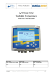
2.1
Mounting the ACTEON 2050 transmitter box
Acteon 2050 mounting diagram
Dimensions (mm)
PONSEL
A
B
C
156.5
181
195.3
Figure 1 - Transmitter mounting diagram
Référence : NOTICE_ACTEON_2050_v001
V : 002
8/67
User manual
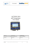
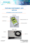
2.2
Connecting the ACTEON 2050 transmitter and MES and Temperature sensors
1
Power supply cable
(230V~ or 24VDC)
2
Line out cable
3
Relay cable (2 channels)
4
4-20mA cable (2
channels)
5
SS sensor (PONCIRMES5-10)
6
Temperature sensor
(PONCPC-T-10)
1
2
4
3
5
6
Figure 2 - Installing a measuring system
Comment:
If the connection cable between the sensor and transmitter is longer than 10 metres, a watertight IP 68
connection box must be used (REF: PON-BJ-E).
PONSEL
Référence : NOTICE_ACTEON_2050_v001
V : 002
9/67
User manual
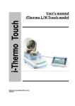
1
Power supply cable
(230V~ or 24VDC)
2
Line out cable
3
Relay cable (2 channels)
4
4-20mA cable (2
channels)
5
SS sensor (PONCIRMES5-10)
6
Temperature sensor
(PONCPC-T-10)
7
Connection box
(PON-BJ-E)
1
2
3
4
7
5
6
Figure 3 - Installation with a connection box
2.2.1 Acteon 2050 wiring:
See appendix (§15) at the end of the document.
PONSEL
Référence : NOTICE_ACTEON_2050_v001
V : 002
10/67
User manual
2.3
Tank-mounting:
2.3.1 Using the stand and protective hood
A PVC protective hood (PON-PDPVC-1) is available for mounting the ACTEON 2050.
The hood is essential in the case of direct exposure to adverse weather or sunshine.
Figure 4 – Transmitter mount and hood
2.3.2 Installing the sensor in the sensor-holder perch (elbowed or straight)
(PONPPCC-CIR or PONPPCD-CIR)
PONSEL
Référence : NOTICE_ACTEON_2050_v001
V : 002
11/67
User manual
It is best to use the elbowed sensor-holder perch with its own installation system when submerging the sensor in
a tank.
Structure for holding sensor
O-Ring seal
SS sensor
Elbowed Sensor-Holder Perch
Lock-nut
Liquid level
30cm
minimum
SS sensor
Liquid flow direction
Figure 5 – Elbowed Sensor-Holder Perch
Comment:
Use elbowed sensor-holder perches in heavily soiled tanks to prevent fibre build-up on the perch.
If there is a directional flow, the sensor's optical slit should be pointing in the direction of the flow.
Installing the SS sensor in the nozzle:
The standard sensor comes sealed to a 10-metre cable connection, making it submersible up to a several bars of
pressure.
1)
2)
3)
4)
Completely unscrew the tightening seal located on the sleeve of the SS sensor beforehand.
Pass the sensor cable through the bottom of the perch (widest end) until it comes out of the other end.
Slide the cable through the perch until the SS sensor sleeve fits into the bottom of the perch.
Slot the SS sensor sleeve insert in the lateral hole located in the lower end of the perch. Tighten the
lock-nut until the sensor is secured in the perch (do not over tighten).
5) Set the perch on the edge of the tank or on the bridge.
PONSEL
Référence : NOTICE_ACTEON_2050_v001
V : 002
12/67
User manual
2.3.3 Installing an Elbowed Sensor-Holder Perch (ref: PONPPCC-CIR) or Straight
Sensor-Holder Perch (ref: PONPPCD-CIR) on QRPM (ref: PONSPFR and
PONSPFR2)
1) Fix the stainless steel QRPM to the infrastructure.
2) Next, fix a sensor-holder perch to the stainless steel QRPM as shown in the diagram below.
Figure 6 - Installing a perch on a QRPM with one or two sliders
A second slider may be added to install a second sensor-holder perch for the temperature sensor (see diagram
above).
PONSEL
Référence : NOTICE_ACTEON_2050_v001
V : 002
13/67
User manual
2.4
In-pipe installation:
The sensors can be supplied for installation in a pressure pipe (<20 bars) with quick release conical
coupling clamps. (see Figure 7 - SS sensor in-pipe installation
)
View from above
Connector
attached
Tightening
screw
2 conical clamps
External weld
Closed conical
clamps
Pipe
MES5-Sp sensor for in-pipe installation with a quick
mounting/dismounting system using conical clamps
Figure 7 - SS sensor in-pipe installation
PONSEL
Référence : NOTICE_ACTEON_2050_v001
V : 002
14/67
User manual
3 ACTEON 2050 transmitter
3.1
Control console:
7
3
5
1
4
2
6
8
PONSEL
1
ENTER key for accessing menus or confirming actions
2
ESC key for exiting menus or cancelling actions
3
key for moving left in menus
4
key for moving right in menus
5
key for increasing a value or selecting the menu above
6
The key for decreasing a value or selecting the menu below
7
Control screen
8
Quarter-turn screw to seal the cover
Référence : NOTICE_ACTEON_2050_v001
V : 002
15/67
User manual
4 Block diagram of ACTEON 2050 menus:
SS sensor
Gain adjust (§6.1.3)
HISTORY
Immediate calibration (§6.1.1)
Differed calibration (§6.1.2)
CALIBRATION
Theoretical calibration (§6.1.4)
CALIBRATION
LOGGER
Temperature sensor
Gain adjust (§6.1.6)
Complete calibration (§6.1.5)
Theoretical calibration (§6.1.7)
Averaging sensor response (§9.1)
CONFIGURATION
Sludge slope coefficient reminder (§0)
MEASURE
Sensor offset adjustment (§9.3)
Graphic screen adjustment (§9.4)
4-20mA output
adjustment
Config. of 4mA and 20mA
stop switches (§9.5.1)
4-20mA output calibration
(§9.5.2)
Threshold adjustment in
mode 1 (§9.6.1)
Relay output
Threshold adjustment in
mode 2 (§9.6.2)
GENERAL
INFORMATION
Threshold adjustment in
mode 3 (§9.6.3)
Measure unit configuration (§9.7)
Language configuration (§9.8)
Factory default configuration reminder (§9.9)
PONSEL
Référence : NOTICE_ACTEON_2050_v001
V : 002
16/67
User manual
5 The measurement window
In measure mode the measurement screen displays various information:Erreur !
6
ACTEON 2050-20 Turbidimeter
MEASURE
2.31 g/l
3
g/l
1
-24 hrs
MEAS
LOG
HIST CAL
1
SS measurement
2
Measurement state indicator:
!
!
1
2
CAL
20.00 °C
3
Mode1 R1
R2
CONF
4
INFO
5
THEOR CAL : Indicates use of the theoretical coefficients as calibration
coefficients.
!
CAL
: Indicates incorrect calibration point on the probe.
!
DRY
WEIGHT
: Indicates differed calibration has been carried out but the dry weight has
not yet been entered.
: No icon displayed means that the last calibration is correct.
3
Temperature transmitted by the temperature sensor
In the event of faulty wiring or uninstalled sensor, the temperature will not be displayed.
Comment: The following icon is displayed if the temperature is higher than the operating
temperature (55°C)
!
HOT
4
R1 and R2 relays: state and operating
mode
Contact is inactive.
Contact is active.
5
ACTEON menu
6
Trend line can be configured from 1 min to 24 hours (with automatic scaling)
PONSEL
Référence : NOTICE_ACTEON_2050_v001
V : 002
17/67
User manual
6 Calibrating the ACTEON 2050
Important information.
Calibration frequency:
The SS sensor must be calibrated (zero + slope) at least once every two weeks, during the regular optics cleaning
process.
However, recalibration is advisable as soon as a shift of more that +/-0.2g/l occurs (during automatic control
with a recently calibrated reference SS meter, or during "dry weight" analysis, while taking account of the fact
that the analysis can sometimes be delayed by up to 24 hours in relation to the current state of the active sludge
measured with the controlled PONSEL SS-meter. Hence the possible use of a "differed calibration" to
compensate for this problem).
If frequent recalibrations are carried out (once a day for example), there is no need to take the sensor + perch out
of the water, clean the optics or zero adjust in clean water. Simply adjust the slope in situ by leaving the sensor
in place in the sludge being measured.
Sensor calibration and positioning procedures: Even though, in our detailed explanations, we have always
mentioned sludge specimens taken from tanks and placed in buckets for sensor calibration, there is no objection
to calibrating the sensor in situ attached to a perch and placed in the measurement medium at the point where it
will subsequently be installed for regular measurements. The sludge content in g/l may already have been
measured for this point ("immediate calibration" or "gain adjust" menus), for instance by using a recently
calibrated reference SS meter, or sludge may be taken from near the optical measurement unit and analysed
while immediately following up with a "differed calibration" without waiting on the results of this analysis.
In this case calibrate in situ during a stable stage in the activation process. Avoid calibrating during bubble
aeration or during stagnation periods. Calibration should preferably take place after aeration. An SS sensor
should be placed in the most stable hydraulic conditions possible, without excessive turbulence or stagnation,
and with regular mixing, so that the SS are perfectly suspended in the medium and that the location is
representative of the SS content in the tank as a whole and in the active sludge area.
In situ calibration remains relevant in the sense that it integrates the hydraulic mixing regime and suspends the
SS, while sludge in a pail only approximates this hydraulic mixing regime, and can thus result in more or less
large measurement differentials in the tank after calibration. Moreover, in situ calibration is carried out at the
tank's temperature thus preventing heat shocks and shifts.
PONSEL
Référence : NOTICE_ACTEON_2050_v001
V : 002
18/67
User manual
6.1
Calibrating the sensors:
Select the calibration menu in the measurement window:
ACTEON 2050-20 Turbidimeter
MEASURE
2.31 g/l
3
g/l
MEAS
Mode1
1
-24 hrs
HIST
CAL
LOG
20.00 °C
CONF
Use the and keys to
navigate the ACTEON menu
INFO
Select the
CALIBRATION
R1
R2
CAL
menu then press ENTER.
SENSORS CALIBRATION
SS SENSOR
Gain adjust
Immediate calibration
Differed calibration
Theoretical calibration
TEMPERATURE SENSOR
Zero rectification
Complete calibration
Theoretical calibration
ENTER: Validate the choice
6.1.1 Two point SS sensor calibration (immediate calibration):
Use the following procedure to calibrate your SS sensor in one go; zero and slope adjustments (gain adjust) are
carried out immediately afterwards. This procedure requires previous knowledge of the SS content of the
activated sludge sample used as the calibration solution. This information can be had either via a recently
calibrated reference SS meter or through analysis of a fraction of the sample sludge immediately after sample
taking then refrigerating the remaining amount at 4°C in an airtight bottle in the dark to prevent fermentation.
Once the analysis results have been obtained, the sludge can be used as calibration solution during this
"immediate calibration" procedure, provided that it is brought up to tank temperature.
Clean the SS sensor beforehand. The sensor optics must be free of dirt and stains (clean optical slit with damp
cloth). See MAINTENANCE chapter (§13.1.3) for cleaning instructions.
PONSEL
Référence : NOTICE_ACTEON_2050_v001
V : 002
19/67
User manual
CALIBRATION
SENSORS CALIBRATION
SS SENSOR
Gain adjust
Immediate calibration
Differed calibration
Theoretical calibration
TEMPERATURE SENSOR
Gain adjust
Complete calibration
Use the andkeys to select
the type of calibration and the
probe to be calibrated.
ENTER: Validate the choice
Select the Immediate
press ENTER.
CALIBRATION
calibration
menu and
OF SS SENSOR
Enter your name:
Durant
ESC: Cancel the procedure
ENTER: Start calibration
Use the and keys to move the
cursor in the name section.
Use the keys and to change the
letters. (The scrolling order of the
letters is A…Z,0..9,?,>,space)
Enter your name or reference then press ENTER
Dip the sensor in clean water with no bubbles (tap water
for example). Preferably, this water must be at the same
temperature as the tank sludge in which the probe will be
placed.
Stir the water with the probe to disperse any bubbles on
the optic windows.
PONSEL
Référence : NOTICE_ACTEON_2050_v001
V : 002
20/67
User manual
OF SS SENSOR
CALIBRATION
Immerse the sensor in
CLEAN WATER
SS content:
g/l
g/l
0.00
0.15
Measure:
WAIT: Nonstable measurement
ESC: Cancel the procedure
ENTER: Validate the zero
AWAIT MEASUREMENT STABILISATION
Press the ENTER key to confirm the first
calibration point
Calibration
Correct
No
Take a representative sample of the measurement medium,
enough to immerse the sensor (in a 5 litre pail or larger).
Dip the sensor in the half-filled pail of sludge and keep
stirring gently to prevent decanting and to keep the SS in
suspension as much as possible.
Advice: The sample sludge must remain at the temperature
of the tank and must not be active calibrate immediately
after sample taking.
Yes
CALIBRATION
If the first calibration point is incorrect, an error
message window appears (see "Error message
information" chapter §6.2.1)
OF SS SENSOR
Immerse the sensor in
your SLUDGE
SS content:
Measure:
5.00
4.20
g/l
g/l
WAIT: Nonstable measurement
Current slope coefficient:
100 %
New slope coefficient:
92 %
ESC: Leave the current slope
ENTER: Validate the new slope
Use the and keys to adjust
sludge concentration
AWAIT MEASUREMENT STABILISATION
Press the ENTER key to confirm the second
calibration point
PONSEL
Référence : NOTICE_ACTEON_2050_v001
V : 002
21/67
User manual
.
Calibration
Correct
No
If the second calibration point is incorrect, an error
message window appears (see "Error message
information" chapter §6.2.2)
Yes
ACTEON 2050-20 Turbidimeter
MEASURE
5.00 g/l
6
g/l
1
-24 hrs
MEAS
HIST
CAL
LOG
20.00 °C
Mode1
CONF
R1
R2
Comment: The
measurement window is
displayed again once the
calibration has been
correctly carried out.
INFO
6.1.2 Two point SS sensor calibration (differed calibration):
The following procedure enables complete calibration of your SS sensor in two successive steps. The delay for
active sludge dry weight analysis can be between several hours to 24 hours or more (centrifugal, filtering,
thermobalance, etc).
1) The first step consists in zeroing the sensor in CLEAN water, then measuring and recording the infrared
emission in your unidentified sludge sample.
Send a fraction of this sample for analysis while carrying out the first step.
PONSEL
Référence : NOTICE_ACTEON_2050_v001
V : 002
22/67
User manual
CALIBRATION
SENSORS CALIBRATION
SS SENSOR
Gain adjust
Immediate calibration
Differed calibration
Theoretical calibration
TEMPERATURE SENSOR
Gain adjust
Complete calibration
Theoretical calibration
Use the andkeys to select
the type of calibration and the
probe to be calibrated.
ENTER: Validate the choice
Select the Immediate
press ENTER.
CALIBRATION
calibration
menu then
SS SENSOR
Enter your name:
Durant
ESC: Cancel the procedure
ENTER: Start calibration
Use the and keys to move the
cursor in the name section.
Use the keys and to change the
letters. (The scrolling order of the
letters is A…Z,0..9,?,>,space )
Enter your name and reference and press ENTER
Dip the sensor in clean water with no bubbles (tap water
for example). Preferably, this water must be at the same
temperature as the tank sludge in which the probe will be
placed.
Stir the water with the probe to disperse any bubbles on
the optic windows.
PONSEL
Référence : NOTICE_ACTEON_2050_v001
V : 002
23/67
User manual
CALIBRATION
SS SENSOR
Immerse the sensor in
CLEAN water
SS content:
Measure:
g/l
g/l
0.00
0.15
WAIT: Nonstable measurement
ESC: Cancel the procedure
ENTER: Validate the zero
AWAIT MEASUREMENT STABILISATION
Press the ENTER key to confirm the first
calibration point
Calibration
Correct
No
Yes
CALIBRATION
If the first calibration point is incorrect, an error
message window appears (see "Error message
information" chapter §6.2.1)
Take a representative sample of the measurement medium,
enough to immerse the sensor (in a 5 litre pail or larger).
Dip the sensor in the half-filled pail of sludge and keep
stirring gently to prevent decanting and to keep the SS in
suspension as much as possible.
Advice: The sample sludge must remain at the temperature
of the tank and must not be active calibrate immediately
after sample taking.
OF SS SENSOR
Immerse the sensor in
your SLUDGE
5.00 g/l
Measure:
WAIT: Nonstable measurement
This will only record the measurement.
Final calibration will take place after
result of the analysis.
ESC: Leave the current slope
ENTER: Validate the procedure
AWAIT MEASUREMENT STABILISATION
Press the ENTER key to confirm the second
calibration point
PONSEL
Référence : NOTICE_ACTEON_2050_v001
V : 002
24/67
User manual
.
Indicates the device awaits dry
weight input following sludge
sample analysis
ACTEON 2050-20 Turbidimeter
MEASURE
2.31 g/l
! DRY WEIGHT
3
g/l
MEAS
Mode1
1
-24 hrs
HIST
CAL
LOG
20.00 °C
CONF
R1
R2
INFO
Comment: The measurement window is displayed again once the calibration has
been correctly carried out
The displayed MEASURE g/l value remains unchanged. The previous slope was not
overwritten and remains displayed (until end of 2nd step), and the SS-meter will give
another useable measurement: this is still attributed to the previous calibration slope
coefficient and not the current one.
2) The second step consists in entering the sludge sample dry weight obtained after a variable delay in order to
complete the SS sensor calibration, which means calculating and recording the new slope.
This step is not affected by the state of the optical sensor, which can be disconnected from the device, connected
and in the air or preferably connected and already in the tank. In the latter case, at the end of this step and
immediately following calibration confirmation and automatic return to MEASURE mode, the g/l value
displayed will be that of the SS content of the sludge measured at the sensor's location in the tank.
CALIBRATION
SENSORS CALIBRATION
SS SENSOR
Gain adjust
Immediate calibration
Content of SS after analysis
Theoretical calibration
TEMPERATURE SENSOR
Gain adjust
Complete calibration
Theoretical calibration
ENTER: Validate the choice
Select the
ENTER.
PONSEL
Use the andkeys to select
the type of calibration and the
probe to be calibrated.
Content of SS after analysis
Référence : NOTICE_ACTEON_2050_v001
menu and press
V : 002
25/67
User manual
OF SS SENSOR
CALIBRATION
Content of SS after analysis
Lab measure: 5.00g/l
Recorded measure! 4.80 g/l
Current slope coefficient:
New slope coefficient:
100%
120%
Use the and keys to adjust
sludge concentration.
ESC: Cancel the procedure
ENTER: Validate the calibration
Press the ENTER key to confirm the second
calibration point
Calibration
Correct
No
If the second calibration point is incorrect, an error
message window appears (see "Error message
information" chapter §6.2.2)
Yes
ACTEON 2050-20 Turbidimeter
MEASURE
5.00 g/l
6
g/l
1
-24 hrs
MEAS
PONSEL
HIST
CAL
LOG
20.00 °C
Mode1
CONF
R1
R2
Comment: The measurement
window is displayed again
once the calibration has been
correctly carried out.
INFO
Référence : NOTICE_ACTEON_2050_v001
V : 002
26/67
User manual
6.1.3 SS sensor slope adjustment:
If clean water zeroing is not required (when the sensor is not excessively dirty), you can recalibrate the sensor in
situ in the active tank sludge, without removing the sensor-holder perch, which can be tedious for example in the
case of daily readjustments. This can also be done in a pail.
SENSORS CALIBRATION
CALIBRATION
SS SENSOR
Gain adjust
Immediate calibration
Differed calibration
Theoretical calibration
TEMPERATURE SENSOR
Gain adjust
Complete calibration
Use the andkeys to select
the type of calibration and the
probe to be calibrated.
ENTER : Validate the choice
ENTER: Validate the choice
Select the Gain adjust
menu and press ENTER.
Take a representative sample of the measurement medium,
enough to immerse the sensor (in a 5 litre pail or larger).
Dip the sensor in the half-filled pail of sludge and keep
stirring gently to prevent decanting and to keep the SS in
suspension as much as possible.
Advice: The sample sludge must remain at the temperature
of the tank and must not be active calibrate immediately
after sample taking.
OF SS SENSOR
CALIBRATION
Immerse the sensor in
your SLUDGE
SS content:
Measure:
5.00
4.20
g/l
g/l
WAIT: Nonstable measurement
Current slope coefficient:
100 %
New slope coefficient:
92 %
ESC: Leave the current slope
ENTER: Validate the new slope
Use the and keys to adjust
sludge concentration.
AWAIT MEASUREMENT STABILISATION
Press the ENTER key to confirm gain adjust.
PONSEL
Référence : NOTICE_ACTEON_2050_v001
V : 002
27/67
User manual
Calibration
Correct
No
If the second calibration point is incorrect, an error
message window appears (see "Error message
information" chapter §6.2.2)
Yes
ACTEON 2050-20 Turbidimeter
MEASURE
2.31 g/l
3
g/l
1
-24 hrs
MEAS
PONSEL
HIST
CAL
LOG
20.00 °C
Mode1
CONF
R1
R2
INFO
Référence : NOTICE_ACTEON_2050_v001
Comment: The
measurement window is
displayed again once the
calibration has been
correctly carried out.
V : 002
28/67
User manual
6.1.4 Returning to SS measurement theoretical calibration:
Theoretical calibration is carried out using SS sensor theoretical coefficients.
SENSORS CALIBRATION
CALIBRATION
SS SENSOR
Gain adjust
Immediate calibration
Differed calibration
Theoretical calibration
TEMPERATURE SENSOR
Gain adjust
Complete calibration
Theoretical calibration
ENTER : Validate the choice
ENTER: Validate the choice
Use the andkeys to select
the type of calibration and the
probe to be calibrated.
Select the Theoretical
press ENTER.
calibration
menu and
THEORETICAL CALIBRATION
CALIBRATION
ATTENTION, you will erase your
calibration coefficients to return to
the theoretical coefficients!
Yes
No
Esc: Cancel the procedure
Enter: Validate the choice
Use the andkeys to select the
procedure confirmation.
Select Yes and press ENTER to return to the
theoretical coefficients.
ACTEON 2050-20 Turbidimeter
MEASURE
2.31 g/l
! THEOR CAL
3
g/l
1
-24 hrs
MEAS
PONSEL
HIST
CAL
LOG
Indicates that the device has
been calibrated with the
theoretical coefficients.
20.00 °C
Mode1
CONF
R1
R2
INFO
Référence : NOTICE_ACTEON_2050_v001
V : 002
29/67
User manual
6.1.5 Two point temperature sensor calibration (complete calibration):
Use the following procedure to completely calibrate your temperature sensor.
You will need a precision thermometer and water at 0°C for this procedure.
CALIBRATION
SENSORS CALIBRATION
SS SENSOR
Gain adjust
Immediate calibration
Differed calibration
Theoretical calibration
TEMPERATURE SENSOR
Gain adjust
Complete calibration
Theoretical calibration
ENTER : Validate the choice
ENTER: Validate the choice
Use the andkeys to select
the type of calibration and the
probe to be calibrated.
Select the Complete calibration menu of the
temperature sensor and press ENTER.
CALIBRATION
TEMPERATURE SENSOR
Enter your name:
Durant
ESC: Cancel the procedure
ENTER: Start calibration
Use the and keys to move the
cursor in the name section.
Use the and keys to change the
letters. (The scrolling order of the
letters is A…Z,0..9,?,>,space )
Enter your name and reference and press ENTER.
Immerse the sensor in a water and crushed ice
mixture at 0.00°C.
PONSEL
Référence : NOTICE_ACTEON_2050_v001
V : 002
30/67
User manual
CALIBRATION
TEMPERATURE SENSOR
Immerse the sensor in
water and ice
Standard:
Measure:
°C
°C
0.00
0.15
:
WAIT: Nonstable measurement
Use the and keys to adjust the
water temperature value.
ESC: Cancel the procedure
ENTER: Validate the zero
AWAIT MEASUREMENT STABILISATION
Press the ENTER key to confirm the first
calibration point.
Calibration
Correct
No
If the first calibration point is incorrect, an error
message window appears (see "Error message
information" chapter §6.3.1)
Yes
Immerse the sensor in water at ambient temperature.
CALIBRATION
TEMPERATURE SENSOR
Immerse the sensor in
water at ambient temperature
Standard:
Measure:
20.00
20.20
°C
°C
:
WAIT: Nonstable measurement
ESC: Leave the current slope
ENTER: Validate the new slope
Use the and keys to adjust the
water temperature value.
AWAIT MEASUREMENT STABILISATION
Press the ENTER key to confirm the second
calibration point.
PONSEL
Référence : NOTICE_ACTEON_2050_v001
V : 002
31/67
User manual
Calibration
Correct
No
If the second calibration point is incorrect, an error
message window appears (see "Error message
information" chapter §6.2.2)
Yes
ACTEON 2050-20 Turbidimeter
MEASURE
2.31 g/l
3
g/l
1
-24 hrs
MEAS
PONSEL
HIST
CAL
LOG
20.00 °C
Mode1
CONF
R1
R2
Comment: The
measurement window is
displayed again once the
calibration has been
correctly carried out.
INFO
Référence : NOTICE_ACTEON_2050_v001
V : 002
32/67
User manual
6.1.6 Adjusting the temperature sensor slope:
If you observe a small measurement error, you may only adjust the slope of your sensor by carrying out the
following procedure:
CALIBRATION
SENSORS CALIBRATION
SS SENSOR
Gain adjust
Immediate calibration
Differed calibration
Theoretical calibration
TEMPERATURE SENSOR
Gain adjust
Complete calibration
Theoretical calibration
ENTER : Validate the choice
ENTER: Validate the choice
Select the Gain
press ENTER.
Use the andkeys to select
the type of calibration and the
probe to be calibrated.
adjust
menu of the temperature sensor and
Immerse the sensor in water at ambient temperature.
CALIBRATION
DU TEMPERATURE SENSOR
Immerse the sensor in
water at ambient temperature
Standard:
Measure:
20.00
20.20
°C
°C
:
WAIT: Nonstable measurement
ESC: Leave the current slope
ENTER: Validate the new slope
Use the and keys to adjust the
ambient water temperature value.
AWAIT MEASUREMENT STABILISATION
Press the ENTER key to confirm slope
adjustment.
PONSEL
Référence : NOTICE_ACTEON_2050_v001
V : 002
33/67
User manual
Calibration
Correct
No
If the second calibration point is incorrect, an error
message window appears (see "Error message
information" chapter §6.3.2)
Yes
ACTEON 2050-20 Turbidimeter
MEASURE
2.31 g/l
3
g/l
1
-24 hrs
MEAS
PONSEL
HIST
CAL
LOG
20.00 °C
Mode1
CONF
R1
R2
Comment: The
measurement window is
displayed again once gain
adjust has been correctly
carried out.
INFO
Référence : NOTICE_ACTEON_2050_v001
V : 002
34/67
User manual
6.1.7 Returning to temperature measurement theoretical calibration:
Theoretical calibration is carried out using the theoretical coefficients (PT100 theoretical slope and offset
zeroing).
Follow the instructions below to carry out theoretical calibration:
SENSORS CALIBRATION
CALIBRATION
SS SENSOR
Gain adjust
Immediate calibration
Differed calibration
Theoretical calibration
TEMPERATURE SENSOR
Gain adjust
Complete calibration
Theoretical calibration
ENTER : Validate the choice
ENTER: Validate the choice
Use the andkeys to select
the type of calibration and the
probe to be calibrated.
Select the Theoretical
press ENTER.
calibration
menu and
THEORETICALL CALIBRATION
CALIBRATION
ATTENTION, you will erase your calibration
coefficients to return to the theoretical
coefficients!
Yes
No
Esc : Cancel the procedure
Enter: Validate the choice
Use the andkeys to select the
procedure confirmation.
Select Yes and press ENTER to return to the
theoretical coefficients.
ACTEON 2050-20 Turbidimeter
MEASURE
2.31 g/l
3
g/l
1
-24 hrs
MEAS
PONSEL
HIST
CAL
LOG
20.30 °C
Mode1
CONF
R1
R2
INFO
Référence : NOTICE_ACTEON_2050_v001
V : 002
35/67
User manual
6.2
SS sensor calibration error message
6.2.1 CLEAN WATER calibration error
One of two messages may be displayed depending on the calibration error.
1) First type of information:
SS SENSOR
CALIBRATION
CALIBRATION IMPOSSIBLE
Out of range! Calibration impossible
Check the sensor or purity of water:
1) The sensor could be clogged
2) Water could include bubbles or
become turbid
If the checking is negative, check the
sensor.
ESC: Escape menu
Your SS sensor response is too low:
1) Clean the sensor head with a water jet, focussing on the insides of the optical measuring channel.
2) Replace the water with clean water.
2) Second type of information:
CALIBRATION
OF SS SENSOR
CALIBRATION IMPOSSIBLE
Out of range! Calibration impossible
Check the sensor:
If the water temperature is <10°C or
>35°C, await the measurement
stabilisation.
Otherwise, check the sensor.
ESC: Escape menu
Your SS sensor response is too high:
1) Check the water temperature.
If you are unable to calibrate the SS sensor after these checks, seek advice from an after-sales service (see last
page).
6.2.2 SLUDGE calibration error
CALIBRATION
SS SENSOR
CALIBRATION IMPOSSIBLE
Out of range! Calibration impossible
Check the sensor and standard sludge:
Possibility of incorrect SS titration
(factor >10) or optics clogged.
If the checking is negative, check the
sensor.
ESC: Escape menu
Your SS sensor response is too low:
PONSEL
Référence : NOTICE_ACTEON_2050_v001
V : 002
36/67
User manual
1) Check the sludge titration (dry weight).
2) Clean the sensor head with a water jet, focussing on the insides of the optical measuring channel.
If you are unable to calibrate the SS sensor after these checks, seek advice from an after-sales service (see last
page).
6.3
Temperature sensor calibration error message information
6.3.1 0°C calibration error
CALIBRATION
TEMPERATURE SENSOR
CALIBRATION IMPOSSIBLE
Offset:
NON CORRECT
ESC: Escape menu
If an error occurs during calibration in water at 0°C:
1) Check the water temperature with a precision thermometer.
2) Check the connection between the temperature sensor and ACTEON 2050.
If you are unable to calibrate the SS sensor after these checks, seek advice from an after-sales service (see last
page).
6.3.2 Ambient water calibration error
CALIBRATION
OF TEMPERATURE SENSOR
CALIBRATION IMPOSSIBLE
Slope:
NON CORRECT
ESC: Escape menu
If an error occurs during calibration in water at ambient temperature:
1) Check the water temperature with a precision thermometer.
2) Check the connection between the temperature sensor and ACTEON 2050.
If you are unable to calibrate the SS sensor after these checks, seek advice from an after-sales service (see last
page).
PONSEL
Référence : NOTICE_ACTEON_2050_v001
V : 002
37/67
User manual
7 VIEWING MEASUREMENT HISTORY
The history menu can be used to consult the last 100 data items recorded and displayed on the trend line.
To view this data, follow the instructions below:
ACTEON 2050-20 Turbidimeter
MEASURE
2.91 g/l
3
g/l
MEAS
Mode1
1
-24 hrs
HIST
CAL
LOG
20.30 °C
CONF
Select the
HISTORY
R1
R2
Use the and keys to
navigate the ACTEON menu.
INFO
HIST
menu and press ENTER.
2.53 g/l
3
g/l
20.00 °C
-4 hrs
1
-24 hrs
ESC: Escape menu
PONSEL
Référence : NOTICE_ACTEON_2050_v001
Use the and keys to move
the cursor along the trend line.
V : 002
38/67
User manual
8 VIEWING THE SENSOR CALIBRATION REPORT
The calibration logger is used to check the reports of the most recent calibrations.
Follow the instructions below to access this information:
ACTEON 2050-20 Turbidimeter
MEASURE
2.91 g/l
3
g/l
-24 hrs
MEAS
1
HIST
CAL
20.30 °C
Mode1
CONF
LOG
Use the and keys to
navigate the ACTEON menu
INFO
Select the
CALIB LOG
R1
R2
LOG
menu and press ENTER.
CALIBRATION LOGGER
Calibration of
SS sensor
CORRECT
Standard 1: 0.00g/L
Standard 2: 5.00g/L
Offset:
0.03g/L
Slope:
110%
Name: Ponsel
Calibration of
Temperature sensor
CORRECT
Standard 1: 0.01°C
Standard 2: 20.00°C
Offset:
1.65°C
Slope:
110%
Name: Ponsel
Esc: Escape menu
Message
CORRECT
THEORETICAL coef.
THEORETICAL slope
THEORETICAL zero
THEORETICAL offset
INCORRECT slope
INCORRECT zero
INCORRECT offset
AWAITING DRY
WEIGHT
PONSEL
List of diagnostic messages for the last calibration:
Explanation
ACTEON 2050 has been calibrated correctly.
ACTEON 2050 is using the theoretical coefficients (slope and zero turbidity). This
message is displayed after a theoretical calibration.
ACTEON 2050 is using the theoretical slope.
ACTEON 2050 is using the theoretical zero turbidity (transmission in clean water).
ACTEON 2050 is using the theoretical offset (SS sensor offset can be adjusted in the
configuration menu (§9.3).
ACTEON 2050 is incorrectly calibrated because the slope calculated during
calibration is incorrect (in this case ACTEON 2050 is using the last correctly
calculated slope).
ACTEON 2050 is incorrectly calibrated because the zero turbidity (transmission in
clean water) calculated during calibration is incorrect (in this case ACTEON 2050 is
using the last correctly calculated slope).
ACTEON 2050 is incorrectly calibrated because the offset measured during offset
adjustment is incorrect (in this case ACTEON 2050 is using the last correctly
measured offset).
ACTEON 2050 is awaiting the information obtained from the sludge analysis in order
to complete the differed calibration.
Référence : NOTICE_ACTEON_2050_v001
V : 002
39/67
User manual
9 CONFIGURING ACTEON 2050
Select the configuration menu in the measurement window:
ACTEON 2050-20 Turbidimeter
MEASURE
2.91 g/l
3
g/l
1
-24 hrs
MEAS
HIST
CAL
LOG
20.30 °C
Mode1
CONF
PONSEL
Use the and keys to
navigate the ACTEON menu.
INFO
Select the
CONFIG
R1
R2
CONF
menu and press ENTER.
WHAT DO YOU WANT TO DO?
Averaging sensor response
Sludge slope coefficient reminder
Sensor offset adjustment
Graphic screen
4-20mA outputs adjustment
Relay adjustment
Measure units
Language
Factory default value reminder
ESC: Escape menu
Référence : NOTICE_ACTEON_2050_v001
V : 002
40/67
User manual
9.1
Configuring sensor response averaging
This configuration makes the sensor response more stable and responsive.
By default, the averaging procedure involves 10 measurements. This means that the displayed value is the
average measurement over the last 10 seconds:
CONFIG
WHAT DO YOU WANT TO DO?
Averaging sensor response
Sludge slope coefficient reminder
Sensor offset adjustment
Graphic screen
4-20mA outputs adjustment
Relay adjustment
Measure units
Language
Factory default value reminder
ESC: Escape menu
Select the ENTER.
CONFIG
Use the andkeys to select
the configuration required.
Averaging sensor response
menu and press
AVERAGING SENSOR RESPONSE
Average on: 10 measures.
1
= Instantaneous answer
100 = Answer very strongly averaged
Esc : Cancel the procedure
Enter: Validate the averaging
Use the and keys to increase
and decrease the averaging.
Select the averaging desired and press ENTER.
CONFIG
WHAT DO YOU WANT TO DO?
Averaging sensor response
Sludge slope coefficient reminder
Sensor offset adjustment
Graphic screen
4-20mA outputs adjustment
Relay adjustment
Measure units
Language
Factory default value reminder
ESC: Escape menu
Comment:
Increase the averaging if your measurement is unstable.
Decrease the averaging if the measurement process is too slow.
PONSEL
Référence : NOTICE_ACTEON_2050_v001
V : 002
41/67
User manual
9.2
Sludge slope coefficient reminder
ACTEON 2050 can be used to retrieve the last 10 slope coefficients:
CONFIG
WHAT DO YOU WANT TO DO?
Averaging sensor response
Sludge slope coefficient reminder
Sensor offset adjustment
Graphic screen
4-20mA outputs adjustment
Relay adjustment
Measure units
Language
Factory default value reminder
ESC: Escape menu
Select the Sludge
and press ENTER.
CONFIG
Use the andkeys to select
the configuration required.
slope coefficient reminder
menu
SLUDGE SLOPE COEFFICIENT
REMINDER:
SLG
STEP_1_06_05_05
STEP_1_05_04_05
STEP_1_06_12_05
STEP_1_06_08_04
STEP_1_06_12_03
STEP_1_06_08_03
STEP_1_06_03_04
STEP_1_06_08_05
STEP_1_06_08_05
: 73.52 %
:
10%
:
60%
:
800%
:
98%
:
23%
:
300%
:
23%
:
300%
:
300%
Use the and keys to select the
10 last slopes (taken during
calibrations).
Select the desired slope and press ENTER.
CONFIG
WHAT DO YOU WANT TO DO?
Averaging sensor response
Sludge slope coefficient reminder
Sensor offset adjustment
Graphic screen
4-20mA outputs adjustment
Relay adjustment
Measure units
Language
Factory default value reminder
ESC: Escape menu
Comment:
indicates the slope currently used.
PONSEL
Référence : NOTICE_ACTEON_2050_v001
V : 002
42/67
User manual
9.3
Adjusting SS sensor offset
You must adjust the SS sensor offset when activating or changing the SS sensor. This operation should be
carried out only once.
WHAT DO YOU WANT TO DO?
CONFIG
Averaging sensor response
Sludge slope coefficient reminder
Sensor offset adjustment
Graphic screen
4-20mA outputs adjustment
Relay adjustment
Measure units
Language
Factory default value reminder
ESC: Escape menu
Use the andkeys to select
the configuration required.
Select the ENTER.
Sensor offset adjustment
menu and press
EXTINCTION OF THE I.R. LIGHT
BEAM
CONFIG
Occult the optical slot
with an opaque ruler
Sensor offset:
12mV
DO NOT VALIDATE
Extinction incomplete!
ESC: Escape menu
Enter: Validate and record
Cover the optical slot with a dark coloured ruler and press
ENTER.
Offset Correct
No
If the offset is too high check that the dark coloured
ruler is positioned properly over the optical slot
(see following page)
Yes
CONFIG
PONSEL
WHAT DO YOU WANT TO DO?
Averaging sensor response
Sludge slope coefficient reminder
Sensor offset adjustment
Graphic screen
4-20mA outputs adjustment
Relay adjustment
Measure units
Language
Factory default value reminder
ESC: Escape menu
Référence : NOTICE_ACTEON_2050_v001
Comment: SS sensor offset
has been correctly adjusted.
V : 002
43/67
User manual
The following message will be displayed if the offset is incorrect:
CONFIG
EXTINCTION OF THE I.R.LIGHT
BEAM:
!!! OUT OF RANGE!!!
Cancellation of offset impossible!!
Check the sensor (the ruler might not
be completely opaque and well
positioned in the optical slot, between
the two port-holes of emission and
reception of the infra-red beam)
ENTER: Escape menu
Press the ENTER key then restart SS sensor offset
adjustment.
CONFIG
PONSEL
WHAT DO YOU WANT TO DO?
Averaging sensor response
Sludge slope coefficient reminder
Sensor offset adjustment
Graphic screen
4-20mA outputs adjustment
Relay adjustment
Measure units
Language
Factory default value reminder
ESC: Escape menu
Référence : NOTICE_ACTEON_2050_v001
Comment: The SS sensor
offset has not been updated.
Your device is using the last
correct offset.
V : 002
44/67
User manual
9.4
Configuring the trend line
The trend line can be used to check regulation cycles and detect anomalies.
Follow the instructions below to adapt the time base to the trend line:
CONFIG
WHAT DO YOU WANT TO DO?
Averaging sensor response
Sludge slope coefficient reminder
Sensor offset adjustment
Graphic screen
4-20mA outputs adjustment
Relay adjustment
Measure units
Language
Factory default value reminder
ESC: Escape menu
Select the ENTER.
CONFIG
Use the andkeys to select
the configuration required.
Graphic screen
menu and press
OF THE GRAPHIC SCREEN
Configuration of the trend curve
7 minutes
Time base:
Showing maximum range: 11 hours
ESC: Cancel the procedure
Enter: Validate the choice
Use the and keys to increase
the time base in order to adjust the
duration of the trend curve. (1 sec to
15 min)
Select the time base chosen and press ENTER.
CONFIG
PONSEL
WHAT DO YOU WANT TO DO?
Averaging sensor response
Sludge slope coefficient reminder
Sensor offset adjustment
Graphic screen
4-20mA outputs adjustment
Relay adjustment
Measure units
Language
Factory default value reminder
ESC: Escape menu
Référence : NOTICE_ACTEON_2050_v001
V : 002
45/67
User manual
9.5
Configuring the two 4-20mA outputs
Comment:
For greater 4-20mA output precision, it is advised to calibrate the outputs during activation.
CONFIG
WHAT DO YOU WANT TO DO?
Averaging sensor response
Sludge slope coefficient reminder
Sensor offset adjustment
Graphic screen
4-20mA outputs adjustment
Relay adjustment
Measure units
Language
Factory default value reminder
ESC: Escape menu
Select the ENTER.
CONFIG
Use the andkeys to select
the configuration required.
4-20mA output adjustment
menu and press
4-20mA OUTPUTS
4-20mA output adjustment
4-20mA output calibration
PONSEL
Référence : NOTICE_ACTEON_2050_v001
V : 002
46/67
User manual
9.5.1 Adjusting 4-20mA output stop thresholds
CONFIG
4-20mA OUTPUTS
4-20mA output adjustment
4-20mA output calibration
Use the andkeys to select
the configuration required.
Select the 4-20mA output adjustment menu and press
ENTER.
CONFIG
4-20mA OUTPUTS
NUMBER 1 FOR SS
4mA adjustment:
0.00g/l
20mA adjustment:
20.00g/l
ESC: Escape menu
Enter: Validate the choice
Use the and keys to increase and
decrease the 4 and 20mA stop values.
Use the and keys to select 4mA or
20mA.
Configure the SS 4-20mA output and press ENTER.
CONFIG
4-20mA OUTPUTS
No 2 FOR TEMPERATURE
4mA adjustment:
-5.00°C
20mA adjustment:
35.00°C
ESC: Escape menu
Enter: Validate the choice
PONSEL
Référence : NOTICE_ACTEON_2050_v001
Use the and keys to increase
and decrease the 4 and 20mA stop
values.
Use the and keys to select
4mA or 20mA.
V : 002
47/67
User manual
Configure the 4-20mA output for temperature and
press ENTER.
CONFIG
PONSEL
WHAT DO YOU WANT TO DO?
Averaging sensor response
Sludge slope coefficient reminder
Sensor offset adjustment
Graphic screen
4-20mA outputs adjustment
Relay adjustment
Measure units
Language
Factory default value reminder
ESC: Escape menu
Référence : NOTICE_ACTEON_2050_v001
Comment: Both 4-20mA
outputs have been
configured correctly.
V : 002
48/67
User manual
9.5.2 Calibrating 4-20mA outputs
Calibrating the 4-20mA outputs improves their level of accuracy by taking into account the device load.
CONFIG
4-20mA OUTPUTS
4-20mA output adjustment
4-20mA output calibration
Use the andkeys to select
the configuration required.
Select the 4-20mA output calibration menu and
press ENTER.
CONFIG
PROCEDURE:
Insert an ammeter between ACTEON
2000 4-20mA output and your
device
des sorties 4-20 mA (
ESC: Escape menu
Enter: To continue
Insert an ammeter between your device (surveillance,
datalogger, etc.) and the ACTEON 4-20mA outputs and
press ENTER.
AMMETER
LOAD
PONSEL
Référence : NOTICE_ACTEON_2050_v001
V : 002
49/67
User manual
CONFIG
4-20mA OUTPUTS
CURRENT GENERATION OF 4mA
Enter the value
read on the SS
4-20mA output
4.00mA
Enter the value read
on the temperature
4-20mA output
4.00mA
ESC: Escape menu
Enter: To continue
Use the and keys to increase
and decrease the 4mA value.
Use the and keys to select the
pH 4-20mA output or the
temperature 4-20mA output.
Adjust the 4mA outputs and press ENTER.
CONFIG
4-20mA OUTPUTS
CURRENT GENERATION OF 20mA
Enter the value
read on the SS
4-20mA output
20.00mA
Enter the value read
on the temperature
4-20mA output
20.00mA
Use the and keys to increase
and decrease the 20mA value.
Use the and keys to select the
pH 4-20mA output or the
temperature 4-20mA output.
Adjust the 20mA outputs and press ENTER.
CONFIG
PONSEL
WHAT DO YOU WANT TO DO?
Averaging sensor response
Sludge slope coefficient reminder
Sensor offset adjustment
Graphic screen
4-20mA outputs adjustment
Relay adjustment
Measure units
Language
Factory default value reminder
ESC: Escape menu
Référence : NOTICE_ACTEON_2050_v001
V : 002
50/67
User manual
9.6
Adjusting relay outputs
The 2 relays can be configured in 3 different modes:
- Mode 1 is used to configure relay R1 on an SS measurement value and relay R2 on a temperature measurement
value.
- Mode 2 is used to configure relays R1 and R2 on two SS measurement values.
- Mode 3 is used to configure:
- relay R1 on two SS measurement thresholds in regulation mode (forced start-up and shutdown delays
can be configured).
- relay R2 on a temperature measurement threshold in alarm mode.
The 2 relays can be configured with the following attributes:
- Alarm threshold: Threshold trigger value
- Hysteresis: Hysteresis value for relay switching (prevents relay hunting)
- Triggering direction:
Above: Means the relay contact is closed above the alarm threshold.
Below: Means the relay contact is open below the alarm threshold.
- Forced start-up and shutdown delay (only in mode 3)
alarme
WHAT DO YOU WANT TO DO?
CONFIG
Averaging sensor response
Sludge slope coefficient reminder
Sensor offset adjustment
Graphic screen
4-20mA outputs adjustment
Relay adjustment
Measure units
Language
Factory default value reminder
ESC: Escape menu
Select the CONFIG
Use the andkeys to select
the configuration required.
Relay adjustment
Configuration of the relays
mode:
- MODE 1: Alarms adjustment
1 threshold on SS
1 threshold on the temperature
- MODE 2: Regulation 2 relays
2 thresholds on SS
- MODE 3: Regulation 1 relay
2 thresholds on SS
1 threshold on the temperature
ESC: Escape menu
Enter: Validate the choice
PONSEL
menu and press ENTER.
Référence : NOTICE_ACTEON_2050_v001
Use the andkeys to select the
configuration required.
V : 002
51/67
User manual
9.6.1 Configuring relays in mode 1:
MODE 1: ADJUSTMENT OF THE
THRESHOLDS AND HYSTERESIS
CONFIG
Rel 1 connected to SS measurement:
Alarm threshold: 2.01g/l Hyst: 0.10g/l
Above the threshold, R1 is on
Rel 2 connected to temperature measurement:
Alarm threshold:20.01°C Hyst: 0.06°C
Above the threshold, R2 is on
ESC: Cancel the procedure
Enter: Validate the choice
Use the andkeys to
increase the values.
Use the and keys to
navigate the selections.
Configure the two relays and press ENTER.
WHAT DO YOU WANT TO DO?
CONFIG
Averaging sensor response
Sludge slope coefficient reminder
Sensor offset adjustment
Graphic screen
4-20mA outputs adjustment
Relay adjustment
Measure units
Language
Factory default value reminder
ESC: Escape menu
Comment: Both relays are
configured correctly in
mode 1.
In the above example, the relays are configured as indicated below:
SS
(g/l)
2.01
Alarm
1.91
threshold
Hysteresis
Inactive
R1
Active
Inactive
Active
Temperature
Alarm
threshold
20.01
19.95
Hysteresis
Active
Inactive
R2
PONSEL
Référence : NOTICE_ACTEON_2050_v001
Inactive
Active
V : 002
52/67
User manual
9.6.2 Configuring relays in mode 2:
MODE 2: ADJUSTMENT OF THE
THRESHOLDS AND HYSTERESIS
CONFIG
Rel 1 connected to SS measurement:
Alarm threshold: 2.01g/l Hyst: 0.10g/l
Below the threshold, R1 is on
Rel 2 connected to SS measurement:
Alarm threshold: 4.51g/l Hyst: 0.10g/l
Above the threshold, R2 is on
Use the and keys to
increase the values.
Use the and keys to
navigate the selections.
ESC: Cancel the procedure
Enter: Validate the choice
Configure the two relays and press ENTER.
WHAT DO YOU WANT TO DO?
CONFIG
Comment: Both relays are
configured correctly in
mode 2.
Averaging sensor response
Sludge slope coefficient reminder
Sensor offset adjustment
Graphic screen
4-20mA outputs adjustment
Relay adjustment
Measure units
Language
Factory default value reminder
ESC: Escape menu
In the above example, the relays are configured as indicated below:
SS
(g/l)
Alarm
threshold
R2
Alarm
threshold
R1
4.51
4.41
Hysteresis
2.01
1.91
Hysteresis
Inactive
Active
Inactive
Active
R1
R2
PONSEL
Active
Inactive
Référence : NOTICE_ACTEON_2050_v001
Active
Inactive
V : 002
53/67
User manual
9.6.3 Configuring relays in mode 3:
CONFIG
MODE 3: HYSTERESIS THRESHOLD
AND DELAY ADJUSTMENT
Rel 1 connected to SS measurement:
High turbidity threshold
Forced start-up delay
Low turbidity threshold
Forced shutdown delay
:
:
:
:
5.50g/l
10 min
3.50g/l
3 min
ESC: Cancel the procedure
Enter : Validate the choice
Use the andkeys to
increase and decrease the values.
Use the and keys to
navigate the selections.
Configure relay 1 in regulation mode and press ENTER.
MODE 3: ADJUSTMENT OF THE
THRESHOLD, HYSTERESIS AND
TEMPERATURE
Rel 2 connected tO temperature measurement:
Alarm threshold: 20.01°C Hyst: 0.06°C
Above the threshold, R2 is on
CONFIG
ESC: Cancel the procedure
Enter: Validate the choice
Use the andkeys to
increase and decrease the values.
Use the and keys to
navigate the selections
Configure relay 2 and press ENTER.
CONFIG
PONSEL
WHAT DO YOU WANT TO DO?
Averaging sensor response
Sludge slope coefficient reminder
Sensor offset adjustment
Graphic screen
4-20mA outputs adjustment
Relay adjustment
Measure units
Language
Factory default value reminder
ESC: Escape menu
Référence : NOTICE_ACTEON_2050_v001
Comment: Both relays are
correctly configured in
mode 3.
V : 002
54/67
User manual
In the above example, the relays are configured as indicated below:
1
SS
(g/l)
2
1.50
10 min
4
3
3 min
0.50
R1
Inactive
Active
Inactive
Active
1
The SS value must go beyond the high threshold for at least 45 sec.
2
Forced start-up delay
3
The SS value must go beyond the low threshold for at least 45 sec.
4
Forced shutdown delay
Comment:
In mode 3, the high threshold must always be 1g/l higher than the low threshold.
During forced shutdown delay, the relay remains open regardless of the measured SS value.
During forced start-up delay, the relay remains open regardless of the measured SS value.
PONSEL
Référence : NOTICE_ACTEON_2050_v001
V : 002
55/67
User manual
9.7
Adjusting measurement units:
ACTEON 2050 can be configured in °C and °F for temperature measurement.
CONFIG
WHAT DO YOU WANT TO DO?
Averaging sensor response
Graphic screen
4-20mA outputs adjustment
Relay adjustment
Measure units
Languages
Factory default value reminder
Select the
CONFIG
Use the andkeys to select
the configuration required.
Measure units
menu and press ENTER.
OF UNITS
Temperature:
°C: degree Celsius
°F: degree Fahrenheit
ESC: Cancel the procedure
Enter: Validate the choice
Use the andkeys to select the
unit desired.
Select the required measurement unit and press ENTER.
CONFIG
PONSEL
WHAT DO YOU WANT TO DO?
Graphic screen
4-20mA outputs adjustment
Relay adjustment
Measure units
Languages
Factory default value reminder
Référence : NOTICE_ACTEON_2050_v001
V : 002
56/67
User manual
9.8
Setting the language:
ACTEON 2050 can be configured in French or English.
CONFIG
WHAT DO YOU WANT TO DO?
Averaging sensor response
Graphic screen
4-20mA outputs adjustment
Relay adjustment
Measure units
Languages
Factory default value reminder
Select the
CONFIG
Use the andkeys to select
the configuration required.
Language
menu and press ENTER.
OF THE LANGUAGE
Select the language:
French
English
ESC: Cancel the procedure
Enter: Validate the choice
Use the and keys to select the
language required.
Configure the language and press ENTER.
CONFIG
PONSEL
WHAT DO YOU WANT TO DO?
Graphic screen
4-20mA outputs adjustment
Relay adjustment
Measure units
Languages
Factory default value reminder
Référence : NOTICE_ACTEON_2050_v001
V : 002
57/67
User manual
9.9
Resetting factory default values:
ACTEON 2050 can be reinitialised with the default parameters:
CONFIG
WHAT DO YOU WANT TO DO?
Averaging sensor response
Graphic screen
4-20mA outputs adjustment
Relay adjustment
Measure units
Languages
Factory default value reminder
Use the andkeys to select
the configuration required.
Select the ENTER.
CONFIG
Factory default value
menu and press
DEFAULT VALUE REMINDER
ATTENTION, you will loose all your
personal adjustments!
Yes
No
ESC: Cancel the procedure
Enter: Validate the choice
Select CONFIG
PONSEL
Use the andkeys to select the
procedure confirmation.
Yes
and press ENTER.
WHAT DO YOU WANT TO DO?
Graphic screen
4-20mA outputs adjustment
Relay adjustment
Measure units
Languages
Factory default value reminder
Référence : NOTICE_ACTEON_2050_v001
V : 002
58/67
User manual
After having reset the factory default parameters, ACTEON 2050 will be configured with the following
parameters:
Sensor response averaging
SS sensor offset
Time base for trend line display
4-20mA output adjustment
Relay output adjustment
Temperature measurement unit
Language
30 measurements
0mV
1 minute
SS output: The 4mA stop is set to 0g/l and the 20mA stop is
set to 20g/l (ACTEON 2050-20) or 50g/l (ACTEON 205050)
Temp. °C output: The 4mA stop is set to -5°C and the
20mA stop is set to 35°C.
The relays are configured in mode 1:
- R1: threshold: 0.00g/l hyst: 0.20 below the threshold,
relay R1 is active.
- R2: threshold: 50.00°C; hysteresis: 0.10 above the
threshold, relay R2 is active
°C
English
10 Information menu
The INFO window provides information on the device type and version. The software and hardware versions
will be requested when you call PONSEL Technical support or After-sales service.
INFO
ACTEON 2050 SS meter
Temperature
Software version XX.XX
Hardware version: XX.XX
ESC: To escape menu
PONSEL
Référence : NOTICE_ACTEON_2050_v001
V : 002
59/67
User manual
11 ADJUSTING THE ACTEON 2050 DISPLAY CONTRAST
The LCD screen contrast can be adjusted to modify the display. This adjustment is only possible from the
measurement window.
ACTEON 2050-20 Turbidimeter
MEASURE
2.91 g/l
3
g/l
1
-24 hrs
MEAS
HIST
CAL
LOG
20.30 °C
Mode1
CONF
R1
R2
INFO
Press the ESC and keys
simultaneously to reduce the
contrast.
Press the ESC and keys
simultaneously to increase the
contrast.
12 Technical specifications:
Technical specifications
Suspended solids measurement
range (temperature compensated)
Suspended solids measurement
accuracy
Temperature measurement range
Temperature measurement
accuracy (°C)
Casing
Display
Operating temperature
Power supply
Max power consumption
4-20mA outputs
Relay outputs
Standard
PONSEL
0-20g/l for Acteon 2050-20
0-50g/l for Acteon 2050-50
+/0.5% of the full scale
-10.00 to +50.00°C
±0.1°C
ABS (IP 65)
Liquid crystal display (LCD) screen
-25°C to +55°C
230/115VAC 60Hz, optional: 12-24VDC
Protected by a 250mA fuse
10VA
2 galvanic isolation outputs (max resistive load 700ohms):
- Adjustable from 0.00 to 20.00g/l or 0.00 to 50.00g/l depending on the
model
- Adjustable from 10.00°C to +50.00°C
2 relays that can be configured in 3 different modes:
- Adjustment in alarm mode (1 SS and 1 temperature (°C) threshold)
- Adjustment in adjustment mode (2 SS thresholds)
- Adjustment in adjustment mode (2 SS and 1 temperature (°C)
threshold)
Interrupting capacity: 3A under 230VAC or 50VDC
CE
Référence : NOTICE_ACTEON_2050_v001
V : 002
60/67
User manual
13 Sensors
13.1 SS sensor
13.1.1 Specifications:
Operating temperature: -10°C to 50°C
Max operating pressure: 5 bars (completely submersible with cable: IP 68 protection)
Material: PVC bodied sensor
Weight: Approx. 1kg
Working range: 0-20g/l (for Acteon 2050-20)
0-50g/l (for Acteon 2050-50)
(Average for urban sludge in real extended aeration)
Emission/reception wavelength: λ0 = 950nm (5mm optical length)
Type of emission: Pulsed
Recurrence frequency: 10Hz
Transmitted signal: intensity of light transmitted at 0° (demodulated continuous low impedance 0-1V signal).
Unaffected by daylight. NTC thermistor temperature compensation (from 5°C to 35°C)
13.1.2 Mechanical diagram:
D=62.4mm
Material:
BLACK
DELRIN
PONSEL
Référence : NOTICE_ACTEON_2050_v001
V : 002
61/67
User manual
13.1.3 Maintenance:
Depending on the type of environment, periodically rinse the probe thoroughly with a water jet, particularly
focussing on the insides of the optical measuring channel.
Never use hard, pointed, rough or blunt objects such as wire brushes, cutters, screwdrivers, knives,
and scrapers to clean the SS sensor. This may damage the probe and scratch the optics or remove
their polish.
Preferably use a soft cloth or paper towel soaked in alcohol to clean the SS sensor optics. Never
scrape or scratch the glass optic windows: Soak them for 1 hour in clean water, surface active
agent + diluted scale inhibitor (for dry dirt layer and limestone deposits) solution.
Advice: For better cleaning results, finish cleaning by rubbing both windows with alcohol-soaked
cotton buds.
Recommended cleaning frequency:
For urban wastewater treatment active sludge, it is recommended to clean the optics every two weeks.
Comment:
The best possible cleaning frequency for optics in this kind of probe can only be determined through
experimentation as the dirt level depends on several factors which vary according to sites, processes, sludge
quality, hydraulics, etc.
This frequency may be increased from one week to one month as the case may be.
If you notice a lot of damping in the measurements:
- Clean the SS sensor (especially the optics)
- Zero calibrate in clean water
PONSEL
Référence : NOTICE_ACTEON_2050_v001
V : 002
62/67
User manual
13.2 Temperature sensor
Stainless steel sensor with DELRIN shaft
Working temperature: -20 to 55°C
Pressure: 5 bars max
Cable: stranded
Measurement principle: PT100 (3-wire assembly)
13.2.1 Maintenance:
Rinse the temperature sensor with a water jet every 3 months.
13.2.2 Mechanical diagram:
Ø20.5
61
85
2 O-ring seals
16
8
316 stainless
steel tube
Ø3
40
PONSEL
Référence : NOTICE_ACTEON_2050_v001
V : 002
63/67
User manual
14 Questions & Answers
14.1 Display screen troubleshooting:
The LCD screen is too dark:
Press ESC then press the key several times to reduce the contrast.
Strange characters are displayed on the LCD screen:
RESET the microcontroller and follow the instructions below to reinitialise the LCD screen:
1) Open the ACTEON 2050 transmitter box.
2) Insert a LEAD or PLASTIC PENCIL in the hole located on the upper part of the box. DO NOT
USE SCREWDRIVERS OR METAL INSTRUMENTS.
Figure 8 – Resetting ACTEON 2050
3) Check that the display screen restarts.
Comment:
Your settings and calibrations are not lost but saved on the EEPROM.
PONSEL
Référence : NOTICE_ACTEON_2050_v001
V : 002
64/67
User manual
14.2 SS measurement troubleshooting:
If you notice a lot of damping in the measurements:
- Clean the SS sensor (especially the optics)
- Zero calibrate in clean water
PONSEL
Référence : NOTICE_ACTEON_2050_v001
V : 002
65/67
User manual
15 Appendix:
Wiring diagram for the ACTEON 2050 terminal:
Relays
SS turbidity
Temp.
Figure 9 - Transmitter wiring terminal layout
If the temperature sensor is not connected, terminal points 28 and 29 must be connected to the
shunt (supplied with the terminal).
If the temperature sensor is connected, the shunt between terminal points 28 and 29 must be
removed.
Before shutting the ACTEON cover, check that the cover sealing joint is correctly positioned in its
groove.
PONSEL
Référence : NOTICE_ACTEON_2050_v001
V : 002
66/67
User manual
After sales service:
PONSEL MESURE
Service SAV
35 rue Michel MARION
56850 CAUDAN - FRANCE
[email protected]
TEL.: +33 (0)2 97 89 25 31
FAX: +33 (0)2 97 76 55 72
Serial number:
PONSEL
Référence : NOTICE_ACTEON_2050_v001
V : 002
67/67