1
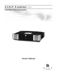
TM
ure
ath
A Few Words from Rupert
“The ‘digital age’ imposes completely new
considerations for high performance analogue
audio design and brings both advantages and
disadvantages with it. These considerations cause
us to completely re-think how to get the very
best out of each new design, such as the
specifically designed transformers I have
TM
incorporated into Pure Path technology.
“The Pure Path “Channel in a Box” - or CIB - is
the result of these careful considerations and
designed to meet the changing needs of engineers and producers for a
powerful yet compact outboard unit combining the features they might
wish for in their console of choice.
TM
“It has become common practice to surround the control room console with
a collection of microphone pre-amps, equalizers and compressors - often
using the original console purely as a monitor.
“The CIB is essentially the input channel of a very high quality console
contained, complete with it’s own power supply, in a 1U rack mounted
assembly. It combines Microphone Pre-amplifier, Line Amplifier, Hi and Lo
Pass Filters, Four Band Equalization and a fully featured Compressor.
“The Mic Pre-Amp, Filters and EQ stages are virtually identical to those used
in the 9098i in-line console including familiar features such as “GLOW” and
“SHEEN”.
“The Compressor is an all analogue design which musically emulates the
best of my past designs and includes a control of the “knee” shape ranging
from “HARD” to a very gentle transition which I have called “&MM”
(and Much More!) the description
a friend gave it!”
1
© 2000 Harman International Industries Ltd.
All rights reserved.
Parts of the design of this product may be protected by worldwide patents.
AMEK is a trading division of Harman International Industries Ltd.
Information contained in this manual is subject to change without notice and
does not represent a commitment on the part of the vendor. AMEK shall not be
liable for any loss or damage whatsoever arising from the use of information or
any error contained in this manual or through any mis-operation or fault in
hardware or software contained in the product.
No part of this manual may be reproduced, stored in a retrieval system,
transmitted in any form or by any means, electronic, electrical, mechanical,
optical, chemical, including photocopying and recording, for any purpose
whatsoever without the express written permission of AMEK.
It is recommended that all maintenance and service on the product should be
carried out by AMEK or it's authorised agents. AMEK cannot accept any liability
whatsoever for any loss or damage caused by service, maintenance or repair by
unauthorised personnel.
PART No: MANCIB Issue 2
Harman International Industries Ltd
Langley House
Third Avenue
Trafford Park
Manchester M17 1FG
United Kingdom
Tel: +44 (0) 161 868 2400
Fax: +44 (0) 161 873 8010
E-mail: [email protected]
Web: www.amek.com
2
TM
ure
ath
Contents
A Few Words from Rupert . . . . . . . . . 1
Unpacking . . . . . . . . . . . . . . . . . . 4
Important Safety Instructions . . . . . . . 5
Installation . . . . . . . . . . . . . . . . . 9
Connections . . . . . . . . . . . . . . . . 10
Audio Connections . . . . . . . . . . 10
Faders . . . . . . . . . . . . . . . . . 10
Compressor Link. . . . . . . . . . . . 10
Operational Guide . . . . . . . . . . . . . 11
Signal Paths . . . . . . . . . . . . . . 11
Mic Input . . . . . . . . . . . . . . . 11
Block Diagram . . . . . . . . . . . . . . . 12
Operational Guide . . . . . . . . . . . . . 14
Line Input . . . . . . . . . . . . . . . 14
Filters . . . . . . . . . . . . . . . . . 16
Equaliser. . . . . . . . . . . . . . . . 17
Compressor . . . . . . . . . . . . . . 20
Output Faders . . . . . . . . . . . . . 22
O/L LEDs . . . . . . . . . . . . . . . . 22
Jumper Options . . . . . . . . . . . . 22
Specifications . . . . . . . . . . . . . . . 23
Warranty . . . . . . . . . . . . . . . . . . 25
3
Unpacking
Check List
The following items are included with the
product. Please retain all packaging
materials until all expected items are
accounted for and found to be operating
correctly.
Packet containing:
4 off M6 mounting screws
4 off plastic washers
Carton
Moulded IEC
mains lead
Protective foam
materials
Channel in a Box Unit
Quality
Certificate
User
Guide
4
Protective foam
materials
Procedure
1. Remove all loose items from the packaging.
2. Slide the unit (along with the protective
foam parts) out of the box.
3. Slide the protective foam parts away from
the unit.
4. Refer to the User Guide before installing or
using.
TM
ure
ath
Important Safety Instructions / Instructions de Sécurité Importances
Cautions Warnings and Notes
Please read this manual carefully before connecting this apparatus to the
mains for the first time! For your own safety and to avoid invalidation of
warranty, all text marked with these Safety Symbols should be read
carefully! Please keep this information!
Cautions
Hazards or unsafe practices which could result in severe personal
injury or death.
Avis
Dangers ou pratiques dangereuses pouvant résulter en des
blessures graves ou causant la mort.
Warnings
Hazards or unsafe practices which could result in minor personal
injury or product or property damage.
Avertissements
Dangers ou pratiques dangereuses pouvant résulter en blessures
personnelles mineures légères ou en dommages à la propriété.
Notes
Contain inportant information and useful tips on the operation
of your equipment.
Notes
Contiennent l’information de inportant et les pointes utiles sur
l’opération de votre équipement.
Earthing / Terre
This apparatus MUST be earthed. Under no circumstances should the mains
earth be disconnected from the mains lead.
Cet appareil DOIT être mis à la terre. La mise à terre ne doit pas être
débranchée du terminal principal sous acune circonstance.
5
Important Safety Instructions / Instructions de Sécurité Importances
Mains Cable / Cable de Secteur
The supplied IEC mains cable must be terminated correctly to the AC mains
supply before use. Use only an approved AC plug or power distribution
device. The Green/Yellow core in the mains cable is a safety ground and
must be connected at all times!
The three cores are colour coded as follows:
Safety Earth
Live
Neutral
=
=
=
Green/Yellow (Green/Yellow USA)
Brown (White USA)
Blue (Black USA)
Le cable de secteur IEC fourni doit être correctement au cable
d'alimentation avant l'utilisation. Utiliser seulement une prise de courant
conforme. Le cable vert/jaune à l'intérieur du cable d'alimentation est la
sécurité terre et doit être toujours connecté!
Les 3 cables à l'intérieur du cable d'alimentation sont de couleurs suivantes:
Prise de Terre
Phase
Neutre
=
=
=
Vert/Jaune (Vert/Jaune USA)
Marron (Blanc USA)
Bleu (Noire USA)
Changing the Fuse / Changer le Fusible
To avoid the risk of fire replace only with same value and type of fuse as
marked on the unit.
Before changing the fuse, always switch off the unit and remove the AC
power cable! Using a flat blade screwdriver, press the fuse cap inwards
gently and twist anti-clockwise to release the cap. Fit the new fuse to the
cap and replace it in the fuseholder by reversing the procedure.
Afin d'éviter un risque de feu, remplacer seulement avec fusible de la même
valeur et type tel qu'indiqué sur l'appareil, 1A (100-230V T). Les fusibles
sont de type IEC 20mm protection-surtension (pour fusibles).
6
TM
ure
ath
Important Safety Instructions / Instructions de Sécurité Importances
Avant de changer le fusible, éteindre l'appareil et enlever la prise
d'alimentation! Utiliser un tourne vis à tête plate, appuyer sur le capuchon
du fusible doucement vers l’interieur et tourner dans le sens contaire des
aiguilles d’une montre pour dégager le capuchon. Mettre le nouveau fusible
dans le capuchon et remetre en place en faisant la procédure inverse.
100V/230V Operation / Fonctionnement
This apparatus does not require any operating voltage adjustment.
Cet appareil n’exige pas l’ajustement de tension qui opérant.
Servicing / Services
The servicing instructions in this manual are for use by qualified personnel
only. To reduce the risk of electric shock, do not perform any servicing other
than that contained in the operating instructions unless you are qualified
to do so. Refer all servicing to qualified service personnel.
Les instructions de services contenues dans ce manuel sont pour utilisation
seulement par des professionels. Pour réduire le risque de choc électrique,
ne tenez aucune opération de service sauf celles contenues dans le manuel
d’opération a moins d’être qualifié pour le faire. Référez toute réparation à
un agent de service professionel.
CAUTION
RISK OF ELECTRIC SHOCK
DO NOT OPEN
!
AVIS: RISQUE DE CHOC ELECTRIQUE
NE PAS OUVRIR
7
WARNING
- For your own safety and to avoid invalidation of the
warranty, please read this section carefully.
• Do not place the apparatus on an unstable surface.
• Do not insert objects through any apertures.
• Do not use this apparatus near water.
• Unplug the unit before cleaning. Clean only with a damp cloth.
• Do not block any of the ventilation openings. Install in accordance with
the manufacturer's instructions.
• Do not install near any heat sources such as radiators, heat registers,
stoves or other apparatus including amplifiers or power supplies that
produce heat.
• Do not defeat the safety purpose of the polarised or grounding-type plug.
A polarised plug has two blades with one wider than the other. A
grounding-type plug has two blades and a third grounding prong. The
wider blade or the third prong are provided for your safety. When the
plug provided does not fit into your outlet, consult an electrician for
replacement of the obsolete outlet.
• Protect the power cord from being walked on or pinched particularly at
plugs, convenience receptacles and the point where they exit from the
apparatus.
• Avoid using mains outlets on the same circuits as air control systems or
other equipment that regularly switches on and off.
• Only use attachments /accessories specified by the manufacturer.
• Unplug this apparatus during lightning storms or when unused for long
periods of time.
• Refer all servicing to qualified service personnel. Servicing is required
when the apparatus has been damaged in any way, such as the power
supply cord or plug is damaged, liquid has been spilled or objects have
fallen into the apparatus, the apparatus has been exposed to rain or
moisture, the apparatus does not operate normally or the apparatus has
been dropped. Unplug the unit under these circumstances.
• Adjust only those controls that are covered by the operating instructions.
• Use only the mains lead provided with the equipment . Other leads may
not have sufficient current rating.
• Do not operate this unit with the cover removed.
8
TM
ure
ath
Installation
Location
This product is designed and screened to minimise internal electromagnetic
emissions and provide immunity to external electromagnetic fields.
To reduce the risk of performance degradation due to external interference,
do not site this unit close to sources of strong magnetic fields such as
power supplies, power amplifiers, loudspeakers etc.
Rack Mounting
This product is designed to be rack mounted using the screws and washers
supplied to help preserve the finish of the facia panel.
The facia graphic layer is under-surface printed to provide a robust hard
wearing surface designed to last the life of the product in virtually any
operating environment.
It is recommended that additional rear or side supports are used in
conjunction with the facia panel fixings, particularly when the unit is
mounted in a flite case or vehicle where vibration and transit shocks can be
expected.
Powering up and Clicks
Clicks may be heard from in/out switches when the product is powered up,
these will dissipate after approximately 10 minutes. This is perfectly normal.
Cleaning
Unplug the unit before cleaning. The product should be cleaned with a soft
brush around the controls. If the facia becomes dirty, use a damp cloth with
a little household soap to remove the dirt. DO NOT use solvent cleaners
under any circumstances or the facia may be permanently damaged and
warranty invalidated!
9
Connections
LINE CHANNEL
POWER
MIC CHANNEL
COMPRESSOR
LINK
Audio Connections
Inputs
The Mic input is electronically balanced via a standard 3 pin female XLR
connector and employs Rupert Neve’s TLA (transformer like amplifier. The
Line input uses a transformer balanced arrangement via a female XLR.
Outputs
The Mic and Line outputs are both transformer balanced via standard 3 pin
XLR male connectors.
All audio connectors follow the European wiring convention:
Pin 1 = Screen; Pin 2 = Hot (+); Pin 3 = Cold (-)
Faders
The Mic and Line faders can be switched out of circuit via the associated
rear panel switches allowing external faders to be used. Connections are via
standard 3 pin male XLR with the following pinout:
Pin 1 = Screen; Pin 2 = Fader Top; Pin 3 = Fader Wiper.
Compressor Link
When enabled, identical gain reduction can take place when two or more
CIBs are linked together. The applied gain reduction is derived from
whichever path has the greatest signal.
CIBs are linked together using a mono or stereo ¼ inch jack lead via the
connector on the rear panel. For more than two units, create a daisy-chain
lead with all the tip contacts wired together (the ring contact is not used).
10
TM
ure
ath
Operational Guide
FILTERS
INPUTS
MIDS
COMPRESSOR
HF
LF
OUTPUTS
Signal Paths
There are three audio signal paths within Channel in a Box, Mic path, Line
path and Compressor side-chain path. By default the side-chain is sourced
from the Mic input. Filters, HF/LF and HMF/LMF can be switched
independently into the Mic, Line or Side-Chain paths.
Selecting "Side-Chain" allows equaliser settings to be inserted into the
Compressor side-chain allowing gain reduction to be frequency dependent.
LF cut can be applied to the side-chain to prevent a bass line “pumping” the
overall signal level. Alternatively, HF boost can be applied which makes the
compressor act more severely on high frequency signals. This can be used to
“de-ess” over sibilant signals.
Mic Input
The microphone input circuit is a T.L.A. (Transformer-Like- Amplifier). It
behaves like a transformer in that if a signal is applied to one input leg
only, no (or very little) output
Mic Path Freq Response
3.0
is the result. A common mode
2.0
input coil rejects common
1.0
50 ohm Source
mode signals and acts as a Low
0.0
Pass Filter for differential
-1.0
inputs.
-2.0
-3.0
150 ohm Source
100
10K
100K 200K
10
1K
A high quality rotary switch
provides a gain range from 0dB
(unity) to +72dB in 6dB steps. Mic gain trim is continuously variable
+/-6dB. The mic input impedance is 5k0 ohms thus producing extremely low
loss from a 150 or 200 ohm microphone.
11
Block Diagram
MIC IN
+48V
Mic Gain
0dB to +72dB
LINE
LINE
GAIN TRIM
-/+6dB
TLA
LINE IN
MIC INPUT
GAIN TRIM
-6dB to +12dB
LINE INPUT
S/C
S/C
IN
IN
I/O METER
INPUT
OUTPUT
MIC IN
M PRE
M POST
LINE IN
L PRE
L POST
INTERNAL
JUMPER
12
MIC
LINE
FILTERS
HPF & LPF
EQUALISER
HF & LF
TM
ure
ath
LINE
EXT FADER
M POST
LINE
M PRE
MIC OUTPUT
MIC
FADER
OPTIONAL
EXT FADER
EXT FADER
GAIN
REDUCTION
METER
L POST
L PRE
LINE OUTPUT
LINE
FADER
OPTIONAL
EXT FADER
G/R
S/C
IN
IN
EQUALISER
HMF & LMF
COMPRESSOR
LINE IN
MIC IN
KEY INPUT
LINK
EXT LINK
13
Operational Guide
FILTERS
INPUTS
MIDS
COMPRESSOR
HF
LF
OUTPUTS
At unity gain, the "microphone" amplifier can handle a balanced input
signal of more than + 20dBu without an attenuator pad (this is a unique
feature amongst "microphone" amplifiers), it could therefore double as an
additional high performance Line Input.
Phantom Power
The 48V switch applies 48V phantom power to the Mic input XLR. Note:
Under no circumstances press the 48V switch if an unbalanced source is
connected to the XLR.
Phase Switch
The Ø (phase) switch allows phase inversion of the incoming signal. The
switch should normally be released.
Line Input
The Line input is a 10k0 ohm (bridging) balanced and floating transformer
design which provides uncompromising isolation and protection against
ground currents and any
Line Path Freq Response
unwanted signals.
3.0
2.0
1.0
Unlike traditional transformers
0.0
the frequency response and
-1.0
distortion are independent of
-2.0
the source impedance of the
-3.0
100
1K
10K
100K 200K
10
preceding equipment. Full low
frequency performance is
maintained even with input levels higher than +20dBu. Gain is provided
on a variable control covering an 18dB range.
14
TM
ure
ath
Operational Guide
The Line Input features a new high performance transformer with
exceptional low frequency performance… as with any genuine transformer
input, this Line Input may be used with either balanced or unbalanced
sources without having to allow for change of gain due to grounding one
leg of a so-called ‘electronically balanced' circuit.
An internal jumper allows the Line Input to be re-configured for use as a
low noise balanced mixing buss when used in conjunction with other Pure
TM
Path products. Refer to the applications ideas leaflet.
Phase Switch
The Ø (phase) switch allows phase inversion of the incoming signal. The
switch should normally be released.
Level Meter
The level meter can display the input or output levels of either path. The
local Meter Source switch selects between Mic and Line paths. The output
section Meter Source switch selects between Outputs and Inputs. The meter
is calibrated to read 0 for output levels of +4dB and normally monitors the
post-fade signal (factory preset) but can be selected to read pre-fade by
internal jumpers.
15
Operational Guide
FILTERS
INPUTS
MIDS
COMPRESSOR
HF
LF
OUTPUTS
Filters
Filters In
Both filters are switched in
together and are only active
with this switch operated,
irrespective of the audio path
they are resident in: Mic, Line
or Side-Chain.
0.0
Filters Response
-3.0
-6.0
-9.0
-12.0
-15.0
-18.0
-21.0
-24.0
10
100
1K
10K
100K
Side-chain Switch
Switches the High Pass and Low Pass filters into the side-chain path.
Note: this switch overrides the Line switch setting.
Line
Switches the High Pass and Low Pass filters from the Mic path into the Line
path.
High Pass
The High Pass filter operates over a frequency range of 22Hz to 300Hz with
a slope of 18dB/Octave allowing the removal of unwanted low frequency
noise components such as rumble and hum.
Low Pass
The Low Pass filter operates over a frequency range of 2.5kHz to 25kHz with
a slope of 18dB/Octave. The extended range allows the filter to remove
unwanted harmonic distortion in the conventional audio band caused by
audio components in the inaudible upper frequency bands.
16
TM
ure
ath
Operational Guide
Equaliser
The EQ section comprises four parametric bands which are independently
selectable in pairs (HF/LF and HMF/LMF) between the Mic path, Line path or
Compressor side-chain.
Low Frequency
The LF band operates over a
frequency range of 30Hz to
300Hz with a variable
cut/boost range of ±18dB.
20.0
EQ - LF Response
15.0
Glow
10.0
5.0
0.0
-5.0
-10.0
-15.0
Peak
Glow and Peak
Peak
20
100
1K
10K
50K
When the Peak switch is
pressed a Bell response is selected. When deselected the response is Shelf.
-20.0
In Bell mode the LF response curve is symmetrical around the current
frequency setting with a Q factor of approximately 0.7 providing the ability
to subtley boost or cut the signal around the chosen frequency.
In Shelf mode the response curve remains flat up to the chosen frequency
where it rolls off at 12dB/Octave.
Glow
Normally the EQ provides steep sided curves allowing powerful tonal
changes. The Glow switch provides a subtle alteration to the response curve
giving greater or less “warmth”, altering the overall sound without
changing its character.
17
Operational Guide
FILTERS
INPUTS
MIDS
COMPRESSOR
HF
Low Mid Frequency
The LMF band operates over a
frequency range of 20Hz to
200Hz with a variable
cut/boost range of ±18dB.
Using the X5 button changes
this to 100Hz and 1kHz
respectively.
LF
20.0
OUTPUTS
EQ - LMF Response
15.0
X5
X5
10.0
5.0
0.0
-5.0
-10.0
-15.0
-20.0
Wide Q
10
100
10K
1K
50K
Q Control
The Q control defines the bandwidth over which the LMF control is active.
The Q range is 0.7 to 2.
High Mid Frequency
The HMF band operates over a
frequency range of 500Hz to
5kHz with a variable cut/boost
range of ±18dB. Using the X5
button changes this to 2.5kHz
and 25kHz respectively.
EQ - HMF Response
20.0
15.0
X5
10.0
X5
5.0
0.0
-5.0
-10.0
-15.0
-20.0
Wide Q
20
100
1K
10K
50K
Q Control
The Q control defines the bandwidth over which the LMF control is active.
The Q range is 0.7 to 2.
Mids In
Both LMF and HMF sections are switched in together and are only active
with this switch operated, irrespective of the audio path they are resident
in: Mic, Line or Side-Chain.
18
TM
ure
ath
Operational Guide
Side-Chain Switch
Switches the HMF and LMF bands of the EQ into the side-chain path.
Note: this switch overrides the Line switch setting.
Line
Switches the HMF and LMF bands of the EQ from the Mic path into the Line
path.
High Frequency
The HF band operates over a
frequency range of 2kHz and
20kHz with a variable
cut/boost of ±18dB.
20.0
EQ - HF Response
15.0
Sheen
10.0
5.0
0.0
-5.0
-10.0
Peak
-15.0
-20.0
Sheen and Peak
10
100
1K
10K
50K
Peak
When the Peak switch is
pressed a Bell response is selected. When deselected the response is Shelf.
In Bell mode the LF response curve is symmetrical around the current
frequency setting with a Q factor of approximately 0.7 providing the ability
to subtley boost or cut the signal around the chosen frequency.
In Shelf mode the response curve remains flat up to the chosen frequency
where it rolls off at 12dB/Octave.
Sheen
Normally the EQ provides steep sided curves allowing powerful tonal
changes. The Sheen switch provides a subtle alteration to the response
curve giving greater or less “warmth”, altering the overall sound without
changing its character.
HF & LF In
Both HF and LF sections are switched in together and are only active with
this switch operated, irrespective of the audio path they are resident in:
Mic, Line or Side-Chain.
19
Operational Guide
FILTERS
INPUTS
MIDS
HF
COMPRESSOR
LF
OUTPUTS
Side-chain Switch
Switches the HF and LF EQ bands into the side-chain path.
Note: this switch overrides the Line switch setting.
Line
Switches the HF and LF EQ bands from the Mic path into the Line path.
Compressor
Threshold
Adjusts the level setting at which gain reduction begins to occur. The range
is –40dB to +23dB.
Attack
Changes the time over which compression begins to occur. The range is 0.3
to 300mS.
Release
Determines the time taken for the gain reduction to stop being applied. The
range is 0.1 to 10 Seconds.
Ratio
Changes the severity of the gain reduction once the signal exceeds the
threshold setting. The range is 1:1 (no compression) to 40:1 (limiting).
20
TM
ure
ath
Operational Guide
&MM (and Much More!)
Selects a different shape to the compression curve which musically
emulates the best of my past designs.
Output Gain
Using compression causes the output signal level to be reduced. This drop in
the output level is therefore compensated for using the output gain
control. The gain range is -6dB to +18dB.
In
Switches the Compressor into the signal path. The default is Compressor in
the Mic path with the Mic signal presented to the Side-Chain.
Line
Switches the Compressor into the Line path with the Line signal presented
to the Side-Chain.
Key
Switches the Side-Chain input to the “other” signal path, e.g. if the
Compressor is in the Mic path, the Line path feeds the Side-Chain and vice
versa.
In many circumstances the CIB will be used with either the Mic or Line path
for the primary signal flow but not both. This allows the secondary path to
be used as an external Key input to the Side-Chain.
Link
When enabled, identical gain reduction can take place when two or more
CIBs are linked together. The gain reduction applied is derived from
whichever path has the greatest signal.
Gain Reduction Meter
If the signal exceeds the compression threshold, the amount of gain
reduction is displayed.
21
Operational Guide
FILTERS
INPUTS
MIDS
HF
COMPRESSOR
LF
OUTPUTS
Output Faders
Both Mic and Line paths are fitted with rotary output faders ranging from
infinity (off) to +10dB with a detented 0dB point. Connections for external
faders (5k or 10k ohm, linear law) are provided via rear panel XLR
connectors and switches.
O/L LEDs
There are three overload LEDs monitoring signal levels on the CIB. All LEDs
are set to illuminate 4dB before clipping. The Mic O/L LED is sourced from
the Mic input trim and the pre fade signal. The Line O/L LED is sourced from
Line input trim and the pre fade signal. The side-chain O/L LED follows the
side-chain input signal and is additionally sourced from two points within
each EQ section when they are switched to side-chain.
Jumper Options
Line Input to Virtual Earth Conversion Option
To configure the Line input to become a virtual earth
input, link pins 3 – 5 and 4 – 6. The factory default
setting is pins 1 – 3 and 2 – 4.
LINE INPUT
1
2
3
4
5
O/P METER
1
2
3
4
5
6
P2
22
VIRTUAL
EARTH
6
P1
Output Meter Source Option
To set the output meter source to pre-fader, link pins 3 – 5
and 4 – 6. The factory default setting (post-fader) links pins
1 – 3 and 2 – 4.
LINE LEVEL
(DEFAULT)
POST FADER
(DEFAULT)
PRE FADER
TM
ure
ath
Specifications
Mic Input
Gain
Line Input
+72dB
Input Impedance
T.L.A. Input Impedance
-6dB to +12dB
Input Impedance
>5,000 Ohms
Input Balance
@1kHz
Gain
Bridging Input Impedance
>10,000 Ohms
Input Balance
Better than 60dBr
@1kHz
Equivalent Input Noise
Overall Noise
(Bandwidth 22Hz-22kHz)
Measured at output
(Measured with gain settings above 54dB)
(Bandwidth 22Hz-22kHz)
Input terminated with 150 ohms
Better than -128dBr
Input terminated with zero ohms
Better than -133dBr
Better than 60dBr
Better than 98dBu
Harmonic Distortion
Unity gain setting, input/output level +20dBu
(Measured with gain at 36dB)
Input terminated with 150 ohms
Input terminated with zero ohms
THD measured @ 1kHz
Better than -129dBr
Maximum Input Level
Balanced and floating transformer
(Measured at unity gain)
Input terminated with 150 ohms
Better than -98dBr
Input @ unity gain
Input terminated with zero ohms
Better than -98dBr
Filters
Harmonic Distortion
At the output, unity gain with Filters in
Input/Output level +20dBu
Better than 0.0015%
-95dBu
Unity gain with Filters in,
Output level +20dBu
Better than 0.002%
1kHz @+20dBu.
Better than 0.0025%
Compressor
Maximum Input Level
T.L.A. @ Unity gain
1kHz @+20dBu.
Distortion
Gain setting 42dBu
THD measured @ 1kHz
+22dBu
Noise
Unity gain setting
THD measured @ 1kHz
Better than 0.002%
Better than -127dBr
+22dBu
Noise
Measured at output, gain unity, ratio @ max,
Equaliser
Threshold @ 0dBu,
attack and release @ mid setting
Better than -94dBu
Noise
Distortion
At the output, unity gain with all EQ in
22Hz-22kHz
Better than 92dBu
Settings as for Noise above,
Input signal @ +10dBu, 1kHz
Distortion
(mostly 2nd harmonic)
Unity gain with all EQ in,
1kHz @+20dBu.
Better than 0.02%
Better than 0.0025%
Outputs
Maximum Output Level
Balanced and floating transformer
Measured at the Mic Path output
+22dBu
Measured at the Line Path output
+22dBu
23
Notes
24