1
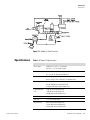
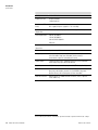
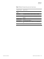
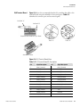
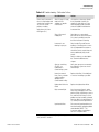
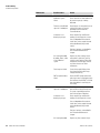
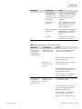
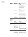
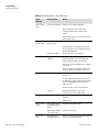
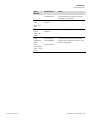
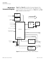
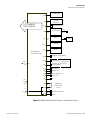
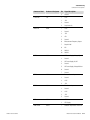
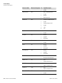
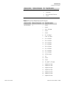
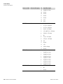
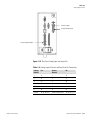
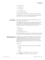
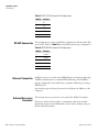
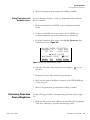
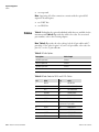
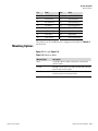
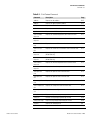
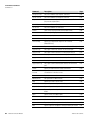
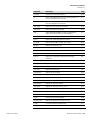
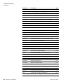
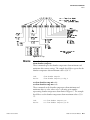
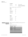
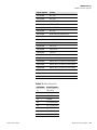
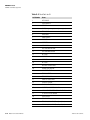
Troubleshooting
Connector Pin Descriptions
Connector Pin
Descriptions
The connector pin descriptions in Table 6–5 through Table 6–12 can be
used along with the board-level connection diagrams to troubleshoot
board-level faults.
Table 6–5. Motherboard Connector Pin Descriptions
Connector Label
Reference Designator
Pin
Signal Description
INTF DATA
J1
1
Ground
2
+RS485 to Interface Board
3
-RS485 to Interface Board
1
Ethernet Output (+)
2
Ethernet Output (-)
3
Ethernet Input (+)
4
NC
5
NC
6
Ethernet Input (-)
7
NC
8
NC
1
+5V
2
+24V
3
+24V
4
Ground
5
Ground
6
Ground
7
+RS485 to Expansion Board
8
-RS485 to Expansion Board
1
+5V
2
+24V
3
+24V
4
Ground
5
Ground
6
Ground
7
+RS485 to Spare Board
8
-RS485 to Spare Board
1
Power Fail Relay N.C. Contact
10-BASE-T
EXPANSION BD
SPARE DATA
I/O
6-12
Model 43i Instruction Manual
J2
J3
J4
J5
Thermo Fisher Scientific