1
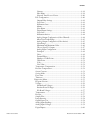
Tables
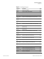
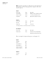
Table 1–1. Model 43i Specifications.................................................................. 1-3
Table 1–2. Model 43i Optional Permeation Oven Specifications...................... 1-5
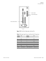
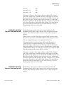
Table 2–1. I/O Terminal Board Pin Descriptions ................................................ 2-6
Table 2–2. D/O Terminal Board Pin Descriptions............................................... 2-7
Table 2–3. 25-Pin Terminal Board Pin Descriptions........................................... 2-8
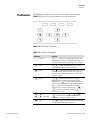
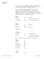
Table 3–1. Front Panel Pushbuttons................................................................... 3-3
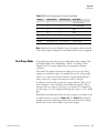
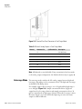
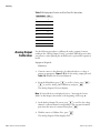
Table 3–2. Default Analog Outputs in Single Range Mode............................... 3-9
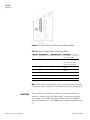
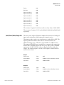
Table 3–3. Default Analog Outputs in Dual Range Mode ............................... 3-10
Table 3–4. Default Analog Outputs in Auto Range Mode ............................... 3-12
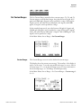
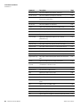
Table 3–5. Standard Ranges............................................................................. 3-14
Table 3–6. Extended Ranges ............................................................................ 3-14
Table 3–7. Analog Output Zero to Full Scale Values ....................................... 3-47
Table 3–8. Signal Types Group Choices........................................................... 3-48
Table 6–1. Troubleshooting - Power-Up Failures............................................... 6-2
Table 6–2. Troubleshooting - Calibration Failures ............................................. 6-3
Table 6–3. Troubleshooting - Measurement Failures........................................ 6-5
Table 6–4. Troubleshooting - Alarm Messages ................................................. 6-8
Table 6–5. Motherboard Connector Pin Descriptions...................................... 6-12
Table 6–6. Measurement Interface Board Connector Pin Descriptions .......... 6-16
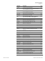
Table 6–7. Front Panel Board Connector Pin Diagram..................................... 6-19
Table 6–8. I/O Expansion Board (Optional) Connector Pin Descriptions ......... 6-21
Table 6–9. Digital Output Board Connector Pin Descriptions.......................... 6-22
Table 6–10. Input Board Connector Pin Descriptions ...................................... 6-23
Table 6–11. Flash Trigger Pack Pin Descriptions ............................................. 6-24
Table 6–12. Flash Intensity Assembly Pin Descriptions .................................. 6-24
Table 7–1. Replacement Parts............................................................................ 7-3
Table 7–2. Model 43i Cables.............................................................................. 7-4
Table 7–3. External Device Connection Components ........................................ 7-4
Table 7–4. Analog Output Channels and Rear Panel Pin Connections............ 7-23
Table 7–5. Analog Input Channels and Rear Panel Pin Connections............... 7-24
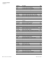
Table 8–1. RS-232 DB Connector Pin Configurations ...................................... 8-12
Table 8–2. RS-485 DB Connector Pin Configuration ........................................ 8-12
Table 9–1. Cable Options.................................................................................. 9-10
Table 9–2. Color Codes for 25-Pin and 37-Pin Cables ..................................... 9-10
Table 9–3. Mounting Options ........................................................................... 9-11
Table B–1. C-Link Protocol Commands .............................................................. B-3
Thermo Fisher Scientific
Model 43i Instruction Manual
xxiii