1
1 Checking Supplied Items
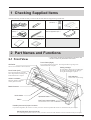
Check the following to make sure that you received all the items that were shipped along with the unit.
Power cord: 1
Blade (ZEC-U1005) : 1
Blade holder
(XD-CH3) : 1
Roller base: 1
* CM-24 only
Cutter tool (for trimming
material) : 1
Tweezers: 1
* CM-24 only
User's manual: 1
Material for test cuts: 1
Test-use application tape: 1
* CM-24 only
CAMM-1 DRIVER
for Windows® 95 : 1
2 Part Names and Functions
* In this manual, the sections that explain both the CM-24 and
the CM-12 shown only illustrations of the CM-24.
2-1 Front View
Pinch Roller (Right)
Press material against the grit roller. This is aligned with the right edge of the
loaded material and set in place.
Grit Roller
This moves the material to the front and rear.
Cutting carriage
The tool (blade or plotting pen) is installed here.
The cutting carriage performs the cutting by
moving the tool left/right or up/down.
Pinch Roller (Left)
Press material against the grit roller.
This is aligned with the left edge of the
loaded material and set in place.
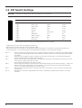
DIP Switches
Used to make various settings.
Guide Line Marks
Material is loaded in alignment
with the guide-line marks.
Blade Protector
Knife Guide
Platen
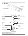
Operation Panel
Pen Force Control Slider
Sets the blade force to be used with the tool.
Parallel (Centronics) Input Connector
In a parallel configuration, this connector is where you need to connect the parallel cable in order to communicate with your computer.
Serial (RS-232C) Input Connector
In a serial configuration, this connector is where you need to connect the serial cable that is used to communicate with your computer.
5