1
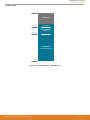
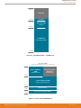
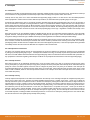
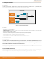
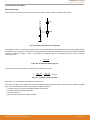
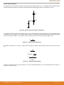
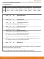
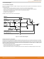
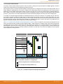
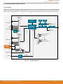
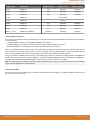
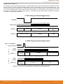
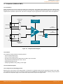
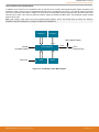
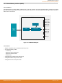
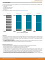
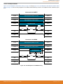
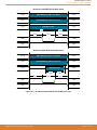
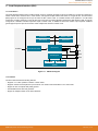
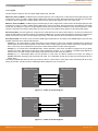
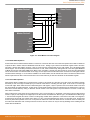
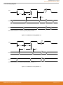
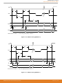
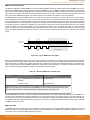
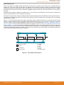
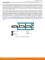
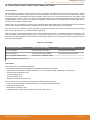
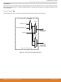
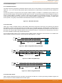
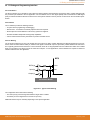
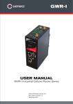
EFM8UB2 Reference Manual
Reset Sources and Power Supply Monitor
9.3.3 Supply Monitor Reset
volts
The supply monitor senses the voltage on the device's supply pin and can generate a reset if the supply drops below the corresponding
threshold. This monitor is enabled and enabled as a reset source after initial power-on to protect the device until the supply is an adequate and stable voltage. When enabled and selected as a reset source, any power down transition or power irregularity that causes
the supply to drop below the reset threshold will drive the RSTb pin low and hold the core in a reset state. When the supply returns to a
level above the reset threshold, the monitor will release the core from the reset state. The reset status can then be read using the
device reset sources module. After a power-fail reset, the PORF flag reads 1 and all of the other reset flags in the RSTSRC register are
indeterminate. The power-on reset delay (tPOR) is not incurred after a supply monitor reset. The contents of RAM should be presumed
invalid after a supply monitor reset. The enable state of the supply monitor and its selection as a reset source is not altered by device
resets. For example, if the supply monitor is de-selected as a reset source and disabled by software using the VDMEN bit in the
VDM0CN register, and then firmware performs a software reset, the supply monitor will remain disabled and de-selected after the reset.
To protect the integrity of flash contents, the supply monitor must be enabled and selected as a reset source if software contains routines that erase or write flash memory. If the supply monitor is not enabled, any erase or write performed on flash memory will be ignored.
Supply Voltage
Reset Threshold
(VRST)
t
RSTb
Supply Monitor
Reset
Figure 9.3. Reset Sources
9.3.4 External Reset
The external RSTb pin provides a means for external circuitry to force the device into a reset state. Asserting an active-low signal on
the RSTb pin generates a reset; an external pullup and/or decoupling of the RSTb pin may be necessary to avoid erroneous noiseinduced resets. The PINRSF flag is set on exit from an external reset.
9.3.5 Missing Clock Detector Reset
The Missing Clock Detector (MCD) is a one-shot circuit that is triggered by the system clock. If the system clock remains high or low for
more than the MCD time window, the one-shot will time out and generate a reset. After a MCD reset, the MCDRSF flag will read 1,
signifying the MCD as the reset source; otherwise, this bit reads 0. Writing a 1 to the MCDRSF bit enables the Missing Clock Detector;
writing a 0 disables it. The state of the RSTb pin is unaffected by this reset.
9.3.6 Comparator (CMP0) Reset
Comparator0 can be configured as a reset source by writing a 1 to the C0RSEF flag. Comparator0 should be enabled and allowed to
settle prior to writing to C0RSEF to prevent any turn-on chatter on the output from generating an unwanted reset. The Comparator0
reset is active-low: if the non-inverting input voltage (on CP0+) is less than the inverting input voltage (on CP0–), the device is put into
the reset state. After a Comparator0 reset, the C0RSEF flag will read 1 signifying Comparator0 as the reset source; otherwise, this bit
reads 0. The state of the RSTb pin is unaffected by this reset.
silabs.com | Smart. Connected. Energy-friendly.
Rev. 0.2 | 64