1
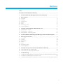
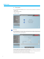
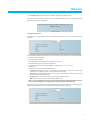
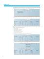
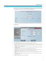
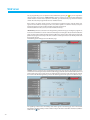
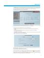
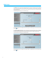
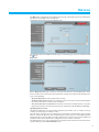
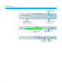
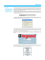
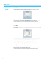
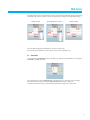
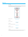
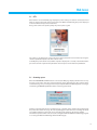
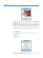
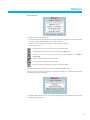
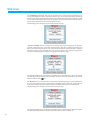
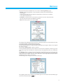
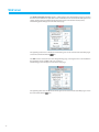
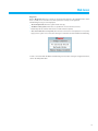
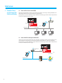
Web Server
5739 92
User Manual
April 09 PC
Web Server
Index
Description of the WebServerAVConfig.............................................................................................................. 4
1
Use of the MH2 with Web pages from Personal computer....................................................... 6
2
2.1
2.2
2.3
2.4
2.5
2.6
2.8
Base functions.............................................................................................................................................................. 9
Scenarios
9
Lighting
10
Automatisms
11
Alarms
12
CCTV
13
Answering system
15
Thermoregulation
16
3
3.1
3.2
3.3
Functions reserved for the “administrator” user........................................................................... 25
Configuration – System
25
Configuration – Language
27
Configuration – Answering system
27
4
Use of the WebServerAVConfig with Web Pages from handheld computer........... 29
5
5.1
5.2
5.3
5.4
5.5
5.6
5.7
Managing the functions.................................................................................................................................... 30
Scenarios
30
Lighting
30
Automation
31
Alarms
32
CCTV
33
Answering system
33
Thermoregulation
34
6 Examples of ways of connection to the WebServerAVConfig............................................. 44
6.1 Home with local area network (LAN)
44
6.2 Home with ADSL subscription with fixed IP
44
7
7.1
7.2
7.3
Troubleshooting...................................................................................................................................................... 45
The WebServerAVConfig does not respond to requests via Ethernet (browser, ping, etc.)45
The WebServerAVConfig does not send e-mail
45
The WebServerAVConfig does not perform the commands sent to the In One by Legrand® systems 45
3
Web Server
Description of the
WebServerAVConfig
The Web Server item WebServerAVConfig can work on a In One by Legrand® system installed in the
house or offi ce. The connection can be made via modem and/or data network (wired or wireless).
The user, using a Personal or handheld computer with commercial browser (e.g. Internet Explorer 6),
can connect locally or remotely with the WebServerAVConfig and, nagivating via Web pages which can
be customised which have icon menus and control pushbuttons, perform the following operations:
• monitoring and command of the Automation (management of loads, lights, rolling shutters etc.),
Burglar-alarm, CCTV, Power management and Thermoregulation systems.
• audio and video real-time connection with the cameras in the CCTV system. In particular, you can:
see the picture transmitted by the camera selected (being able from the PC to alter the picture
quality, framing and zoom), listen to the message recorded by the microphone of the camera
selected (remote audible monitoring) and send a message to the loudspeaker associated with
the camera selected (2-way real-time audio communication from Personal computer);
• listen to the audio messages and see the pictures on the Personal computer sent by video handset
to the WebServerAVConfig when the “Video door entry answer machine” function is active.
The audio message and the picture can also be sent via e-mail to an electronic postal address.
Thermoregulation
Automation
Burglar-alarm
CCTV
USB
Speed
Full
Link
USB
Aux
Lighting
System
5739 92
ETH
SCS
SCS
SCS
SCS
DC
WebServerAVConfig
Video door entry
You can also receive an e-mail message with attached pictures in your post box when events are
signalled as occurring in the burglar-alarm system.
With the activation of the In One by Legrand® WEB service, the house can be managed remotely not
only from the PC or handheld connected to the Internet, but also from a landline or mobile phone.
4
Web Server
If the Personal Computer is to dialogue with the WebServerAVConfig it must have an Ethernet
network card or a modem.
Each WebServerAVConfig in the system will be connected to the data network or to the telephone
line, to the 2-wire cable item 336904 of the digital video door entry system and to the 2-wire cable
item L4669S of the burglar-alarm system.
Example of connection to the WebServerAVConfig with Handheld by means of Router Modem Wi-Fi
Telephone line
Internet
ISP
USB
Speed
Full
USB
Link
Aux
System
5739 92
* Handheld
ETH
Modem Router
Wi-Fi
SCS
AV IN
SCS
AV
SCS
AV OUT
SCS
DC
AI
ethernet
In One by Legrand®
systems
LAN network
Example of connection to the WebServerAVConfig with Handheld by means of GPRS connection
of a mobile phone
* Handheld
®
USB
Speed
GPRS mobile
phone
Bluetooth
Attention: configure the
WebServerAVConfig with the
TiWebServerAVConfig program.
Full
Link
USB
Aux
System
5739 92
ETH
SCS
SCS
SCS
SCS
DC
WebServerAVConfig
* Operation guaranteed with Handhelds with Windows Mobile – Windows CE 2002 or higher operating
system. Correct operation is not guaranteed with Palm OS..
5
Web Server
1 Use of the MH2 with
Web pages from
Personal computer
The interaction with the In One by Legrand® systems connected to the WebServerAVConfig can
occur locally (on LAN or Wi-Fi network) and remotely (accessing them with public Internet address
or via modem) through Web pages where the types of action to be performed and the control
pushbuttons have already been configured and customised.
With connection via modem (local telephone line) the user must configure the Remote Access
function on the control PC (for more information see “Guide to the configuration of the Networks
and the PC”).
When the browser has been started, the numerical address (or URL – Uniform Resource Locator –
standard method for indicating the logic address of a specific network resource, e.g. 192.168.1.35)
of the WebServerAVConfig which the program must connect to set up a direct connection line to
the In One by Legrand® system must be indicated.
The connection and the data exchanged with the site are protected.
In One by Legrand® uses the SSL 128 bit encryption system, based on the Secure Sockets Layer
protocol.
All the application pages are downloaded using this protocol which guarantees their integrity and
origin.
Today 128-bit message cryptography represents the best security system for sending reserved
information via Internet and is the system used by banks throughout the world.
Because it is standard, it is used by the main Browsers (Explorer, Opera). If Internet Explorer is used,
after entering the URL the encryption system rewrites http:// as https:// (the s indicates that the
site uses the SSL protocol) and displays the following security alert.
Press Yes to access the identification page.
6
Web Server
Note the padlock in the Internet Explorer window (bottom right), indicating a secure connection.
On moving the mouse above the padlock the type of protection protocol used will be indicated.
To display the protection certificate click on the padlock or on the “display certificate” twice in the
security alert window.
Note: the protection certificate
is issued by Legrand.
Every time you connect to the
WebServerAVConfig the security
alert is shown, as reminder and
guarantee of a secure system,
because it is not visible and
cannot be edited by third
parties.
The certificate indicates: the issuer (Legrand), the date of validity of the protection certificate and
who it was issued to.
7
Web Server
The connection between PC and WebServerAVConfig is available for one access at once; several
users cannot connect with the WebServerAVConfig and thus with the system at the same time.
This is fundamental to guarantee consistency between the actions requested (commands) and
carrying them out. Obviously the access to the system command pushbuttons is subordinate to
passing an “identification page” where a login (identification name) and a password, known only
by the user, are requested.
If the identification has been successful the system can display the list of all the functions which can
be activated and which were defined in the WebServerAVConfig configuration phase by means of
the TiWebServerAVConfig program.
Attention: if no action is
performed for a time defined
in the programming phase, the
WebServerAVConfig returns the
user to the identification page
whenever a second user enters
the correct login and password
values.
Identification
page
Control
home page
Two types of user can access the Web pages:
• administrator user
• user user
The administrator user can navigate in the same pages as the user user and can also access the
CONFIGURATION function and define some WebServerAVConfig parameters such as, for example,
the number of pictures to be saved in the video door entry answering system, the e-mail address to
which alarm signals and/or messages in the answering system should be sent, login and password
for access to the pages as user user, etc.
Note: the administrator user
login and password are defined
with the TiWebServerAVConfig
program.
8
Web Server
Example of a Web page:
WebServerAVConfig
identification name
WebServerAVConfig
address
Functions
available
selection area
2 Base functions
Exit
pushbutton
Access to the
different pages
System state
Activation interrogation
pushbuttons pushbutton
State request
pushbutton
Information and
operation area
State of the
relevant light
Icon of the
function
selected
2.1 Scenarios
By pressing pushbuttons displayed in the Web page this function can activate the scenarios saved
in the Automation system scenario module item 03551.
The confirmation message: Command sent is displayed in the page for each command sent successfully.
9
Web Server
2.2 Lighting
In managing the LIGHTING function the web page displays the pushbuttons for sending the ON/
OFF, Timing, Flashing and dimmer control command.
Detail of the pushbuttons and their functions:
Dimmer
setting
Display light
state
State request
pushbutton
Timing selection
ON/OFF
commands
Flash frequency
selection
Confirmation
message
The confirmation message: Command sent is displayed in the page for each command sent successfully.
10
Web Server
2.3 Automatisms
In managing the AUTOMATISMS function the Web page displays the pushbuttons for sending the
UP/DOWN/STOP and State request command.
The confirmation message: Command sent is displayed in the page for each command sent successfully.
11
Web Server
2.4 Alarms
When the ALARMS function is selected the Web page displays the burglar-alarm system state with a
text. When there is an alarm the message indicates the type of alarm (e.g. intrusion alarm, tampering
alarm or technical alarm) and where it came from (e.g. living room).
If there are no alarm events the message:
No alarm activated
If there is an alarm event the message:
anti-intrusion alarm: <zone name>
where <zone name> is the name of the zone where the intrusion event occurred. It can be customised with the TiWebServerAVConfig program.
Signalling alarms via e-mail:
The WebServerAVConfig can signal anti-intrusion events or auxiliary alarms, such as gas leak, flooding, etc., by sending e-mail messages via modem or LAN.
The texts of the messages sent are predefined and correspond to the alarm definitions given by the
TiWebServerAVConfig application. A compressed .zip file can be attached to the messages containing the pictures in .jpg format from the burglar-alarm system camera.
To activate this function when programming the device by means of the TiWebServerAVConfig application enter the addresses of the addressee, the sender, the post server IP (SMTP) and any Router
of the LAN to which the PC configured to receive e-mails is connected.
The administrator user can also configure the e-mail address for transmission via modem in the
CONFIGURATION menu “System” Web page.
12
Web Server
2.5 CCTV
When the CCTV function is selected and the “Activate” pushbutton pressed, the Web page displays the
picture sent from the camera selected in the CCTV system connected to the WebServerAVConfig.
By pressing the pushbuttons in the page the user can interact by selecting the camera required,
editing the picture parameters such as brightness, contrast and colour or enlarging a specific area
of the picture.
If the camera selected is an entrance panel camera, the door lock and lighting can be activated.
Note:to increase the picture
frame rate (number of pictures
displayed in a second) alter the
quality. In particular, the lower
the quality required, the higher
the frame rate.
Detail of the pushbuttons and the functions performed:
Window to display the
camera to be activated
Activation and deactivation of the
selected camera
Activating door lock and light commands
Horizontal/vertical selection of the
part enlarged
Brightness - Setting the brightness
Contrast - Setting the contrast
Attention: the CCTV function
is not available if the Video
door entry answering system is
recording a message.
Quality - Setting the picture quality
(the more the picture definition is raised the longer it takes to refresh)
Zoom - Picture enlargement/reduction x 2
13
Web Server
For Internet Explorer the possibility of displaying the camera pictures by means of an ActiveX has
been added. This Windows “external module” can display the pictures more smoothly. To activate it
select the pull-down menu and select the option depending on the connection network used.
On pressing the activation pushbutton the following appears:
This is because Windows libraries are needed to use ActiveX. If they are not on the PC they must be
downloaded from the Internet. If you have a fast ASDL connection the operation takes about ten
seconds, with a 56kb modem it takes up to ten minutes.
monday, June 26, 2008 - 15:10:52
Using the ActiveX the
data on the date and time
of filming are entered in
the picture.
Pressing on ? a Help
window appears which
explains the meaning of
the term “ActiveX”.
After installing ActiveX on your PC and pressing “Activate ActiveX” the operation described above is
no longer performed, even if the message continues to appear, and the passage from “slow” picture
to “smoother” picture will be immediate.
To deactivate the application click on the pull-down window and select No ActiveX.
On pressing the deactivation pushbutton the following appears:
14
Web Server
2.6 Answering system
When the ANSWERING SYSTEM function is selected, the Web page displays pictures and voice messages from the entrance panel, saved by the WebServerAVConfig if the “Video door entry Answering
system” function was activated.
By pressing the push buttons in the page, the user can listen to/cancel the messages and click on
the pictures to enlarge them.
The user can configure the answering system service with the TiWebServerAVConfig program or
via the Web pages (as administrator user) by selecting CONFIGURATION.
Using the TiWebServerAVConfig program the WebServerAVConfig can be configured so that the ANSWERING MACHINE function can also be activated by pressing a In One by Legrand® Automations system
control push button and/or switching on the burglar alarm. Also, when the ANSWERING MACHINE has
been activated, the WebServerAVConfig can activate a signal light, by means of Automation system
devices. The installer must set up the Automation system to perform the functions described above.
Pictures saved.
The number can be configured by the Web
page or by the TiWebServerAVConfig program.
Picture selected for display (to return to displaying all the
pictures recorded select the message to be heard again).
Detail of the pushbuttons and the actions performed:
Listen to message
Activate/deactivate answering system
pushbutton
Cancel message
Message date and time indication
Indication in % of the memory used
15
Web Server
2.8 Thermoregulation
When the TEMPERATURE CONTROL function is selected, the web page displays three pushbuttons:
– CONTROL UNIT;
– NON–CONTROLLED ZONES;
– EXTERNAL SENSORS.
Control unit
When “CONTROL UNIT” is selected, the web screen displays three areas: General, Programming and
Diagnostic. The first is for checking the system status, the second for setting the system parameters
and the third to perform a system diagnostic.
The “General” Web page is divided into two areas which, before they are displayed, are interrogated
by proposing the “system interrogation in progress” message.
The state of the thermoregulation system is summarised in the upper part, supplying information
similar to that which can be read on the control unit display.
The individual system zones or all of them can be interrogated in the low part.
16
Web Server
• The “update state” text. Press on this to ask the control unit to update again.
If for some reason the control unit does not respond to the initial state or updating interrogation
the following message is displayed:
Interrogating the zones
By selecting on the pull-down menu, the individual zones (sensors) can be interrogated or all
together.
The information displayed is that which is visible on the control unit when the zone temperature
is checked (“zone state” menu):
• the zone (sensor) chosen;
• the temperature measured in the room where the sensor is;
• the temperature expected and set for that zone;
• the position of the sensor knob (Local OFF, Local Protection, 0, +/-1, +/-2, +/-3)
in that zone;
• the zone mode of operation which will indicate:
– “Automatic” when the sensor is set to work in the same modes selected in the control unit
when these are in Week program, Scenario, Weekend or Holiday;
– “Manual” when, independent of the sensor setting, the control unit is in Manual mode or when
the sensor itself is in Manual mode;
– “Antifrost” when the sensor has been set remotely in Antifrost mode;
– “Off” when the sensor has been set remotely in Off mode.
• If a fan-coil speed regulation sensor is installed, the page will also display the different speeds
that can be selected by the user (Minimum, Average, Maximum and Automatic).
When the sensor is faulty and does not respond to the interrogations dashes “-“ will be displayed
apart from for “Mode” because this information is supplied by the control unit:
17
Web Server
If instead the bus connection is broken, there is no power supply on the system or the WebServerAVConfig
does not communicate, just a series of dashes “-“ will be shown for all the items.
Selecting “All the zones” from the pull-down menu all the zones on the system configured with the
TIMSERVER2 software displayed as below are interrogated one by one:
The same information can be read for the single request of the zone collected in a single vertically
sliding window. The individual lines give:
• the zone name;
• the temperature measured;
• the temperature expected;
• the position of the sensor knob;
• the zone mode of operation.
• The presence of a Fan-coil sensor with corresponding set speed.
If one or more sensors is faulty dashes “-“ are displayed.
18
Web Server
When the bus connection is broken and no sensor/zone manages to communicate all the zones will
show dashes “-“. If the message “The control unit does not respond” appears in the part reserved for
the control unit, the zones which show dashes mean “zone not reached.”
Programming
The “Programming” Web page is divided into two pages: Control unit and Zones.
The parameters for the control unit are set in the “Control unit” page in the seven modes provided:
• weekly, in which you can select a week program configured with the TiWebServerAVConfig
software or the last program selected;
• scenarios, in which you can select a scenario configured with TiWebServerAVConfig or the last
program selected;
• weekend, in which a weekend day can be activated up to the time chosen.
The time set must be later than the current time and if no time is set the command is not sent;
• holiday, in which the holiday can be activated with ending date and time;
• manual, in which temperatures can be set between 5 and 39.5°C, with deviation of half a degree;
• antifrost/thermal protection, in which the temperatures are fixed at 7°C (antifrost) or 35°C (thermal protection);
• OFF, in which the system can be switched OFF.
19
Web Server
For any programming to be accepted it must be followed by pressing the key on the right of the
chosen program. The message “command sent” is given in response. To check remotely whether the
control unit has received and accepted the command, go to the “General” page and check that the
control unit and/or the programmed zone has modified its state.
If the system is in “winter” mode (season), in selecting the programs/scenarios only the winter ones
appear and the “antifrost” mode appears. Vice versa, if the system is in “summer” mode (season), the
summer programs/scenarios and the “thermal protection” mode appear.
The winter/summer mode (season) cannot be modified remotely.
“Weekend day” must be activated in the “Programming-Control unit” page selecting the program set
in the control unit which is to be run on that weekend day and entering the date (in the format dd/mm/
yyyy) and time (in the format hh/mm) of that day. When the system reaches that weekend day it will
perform the program selected up to the time set. At the end the system returns to “Weekly” mode with
the program selected.
The following picture will appear in the “General” page:
“Holiday” must be activated in the “Programming-Control unit” page selecting the program set in the
control unit and entering the date (in the format dd/mm/yyyy) and time (in the format hh/mm) of the end
of the holiday period. The system will stay in antifrost/thermal protection mode until that date and will
then return to the Week programming selected. The following picture will appear in the “General” page:
The signalling of all the zones in “Holiday” mode will be given on the Web pages and on the Control
unit with the wording “Holiday” and the number of days in which this state will be maintained, with the
addition of the
icon.
20
Web Server
The “Manual” mode is activated in the “Programming-Control unit” page by selecting “Manual” in the
“Set mode” pull-down menu and setting the temperature value required. The system will keep all the
zones at this temperature until this mode is modified (remotely or in the control unit).
The following picture will appear in the “General” page:
The signalling of all the zones in “Manual” mode will be given on the Web pages and on the Control unit
with the wording “Manual” and the temperature value set, with no other icon.
The parameters for the individual zones are set in the “Zones” page:
• manual, in which temperatures can be set between 5 and 39.5°C, with deviation of half
a degree;
• antifrost/thermal protection, in which the temperatures are fixed at 7°C (antifrost)
or 35°C (thermal protection);
• automatic, to return the zone selected to the operation set on the control unit when this zone
has not been forced to different operation;
• OFF, in which the system can be switched OFF.
The settings of the individual zones (sensor) can be “unlocked” and then reactivated whenever they are
locally set in OFF or antifrost/thermal protection.
Its operation will be put to that set on the control unit.
For any programming to be accepted it must be followed by pressing the key on the right of the
chosen program. The message “command sent” is given in response. To check remotely whether the
control unit has received and accepted the command, go to the “General” page and check that the
control unit and/or the programmed zone has modified its state.
21
Web Server
The “Manual” mode is activated in the “Programming-Zones” page by selecting the zone to be modified
in the “Set mode” pull-down menu and “Manual” in the “Set mode” line and entering the temperature
value required. The zone chosen will remain at this temperature until this mode is modified (remotely
or in the control unit).
The following picture will appear in the “General” page:
The signalling of the zone in “Manual” mode will be given on the Web pages and on the Control unit
with the
icon.
The “Antifrost/Thermal Protection” mode is activated in the “Programming-Zones” page, selecting the
zone to be modified in the pull-down menu and “Antifrost” in the “Set mode” line if the system is in “winter” mode (season) and “Thermal device protection” if the system is in “summer” mode (season).
The following picture will appear in the “General” page:
The signalling of the zone in “Antifrost” mode will be given on the Web pages and on the Control unit
with the
icon.
22
Web Server
The “Off” mode is activated in the “Programming-Zones” page, selecting the zone to be modified in the
pull-down menu and “Off” in the “Set mode” line.
The following picture will appear in the “General” page:
The signalling of the zone in “Off” mode will be given on the Web pages and on the Control unit with
the
icon
Diagnostics
On the “Diagnostic” Web page a check can be made of the devices in the individual zones and, if
there is a fault on one or more zones of the system, the anomaly can be signalled. The following messages can be displayed:
• “No anomaly found” when the system works correctly;
• “Problem on the system” when there is a problem in one or more zones/sensors, followed by the
list of zones where there is a fault and its description;
• “The control unit does not respond” when the bus connection is interrupted, there is no power
supply on the system or no sensor/zone manages to communicate with the WebServerAVConfig.
Signalling faults via e-mail:
The WebServerAVConfig can signal thermoregulation system faults, such as a faulty sensor, by
sending e-mail messages via modem or LAN.
The texts of the messages sent are predefined and correspond to the definitions of the possible
faults. To activate this function, when programming the device by means of the TiWebServerAVConfig application, enter the addresses of the addressee, the sender, the post server IP (SMTP) and
any Router of the LAN to which the PC configured to receive emails is connected.
The administrator user can also configure the e-mail address for the transmission via modem in the
“System” Web page of the CONFIGURATION menu.
23
Web Server
Non-controlled zones
If the system includes temperature measurement sensors only (non-controlled zones), the temperature detected by them can be displayed in the appropriate web page.
External sensors
If the system includes external radio sensor, the temperature detected by them may be displayed.
24
Web Server
3 Functions
reserved for the
“administrator” user
If you access the Web pages as administrator user, the CONFIGURATION box appears in the function bar. It has three pages:
• SYSTEM
• ANSWERING SYSTEM
• LANGUAGE
3.1 Configuration – System
In this page the administrator user can configure the login and password data for the user user (Web
access), login/password and telephone for access to the Internet via modem (internet provider), the
number of rings for access to the modem from the local telephone line, the sender and addressee
of the e-mails and the Ethernet configuration parameters for access to the WebServerAVConfig.
To confirm the entered data press the
pushbutton.
Clicking on “TIME/DATE” gives access to the page to configure the date, time and time zone data.
To confirm the entered data press the
pushbutton.
25
Web Server
On clicking on “DIAGNOSTIC” the page containing the device parameters and the diagnostic message
(e.g.: No anomaly found) is displayed.
Click on “RANGE IP” to display the page where the IP addresses can be entered, for connection without
password.
26
Web Server
3.2 Configuration – Language
In this page the administrator user can configure the WebServerAVConfig Web page display language
The set default language is Italian, but all the main European languages are available.
When the language required is selected and confirmed the Web pages will be displayed in the new
language. If the system is performing other operations a wait message will appear.
3.3 Configuration – Answering system
In this page the administrator user can configure: the number of photos (from 1 to 16) which are
saved on each call from the entrance panel, select, if provided, a voice presentation message, enable
sending the messages recorded via e-mail and activate/deactivate the video door entry answering
system service.
Details of the pushbuttons and the functions performed:
Number of photos which the WebServerAVConfig
can save for the answering system service
Confirmation
pushbutton
27
Web Server
Pushbutton to hear
the message locally
Pushbutton to access the box of the PC
where the presentation
messages are (.wav file)
Pushbutton to send the
message to the WebServerAVConfig
Indication in % of the
memory used
Answering system ON/
OFF pushbutton
Box to enable
e-mail via Ethernet
28
Confirmation
pushbutton
Web Server
4 Use of the
WebServerAVConfig
with Web Pages from
handheld computer
The interaction with the In One by Legrand® systems connected to the WebServerAVConfig can also
occur locally (with Wi-Fi connection, Bluetooth or GPRS) through Web pages specially written for
use from handheld. The Web pages, previously configured and customised in the types of action
to perform, have control buttons for the communication with the system (for the configuration see
the TiWebServerAVConfig User manual).
When the browser is started, enter the numerical address (or URL – Uniform Resource Locator –
standard method to indicate the logic address of a specific network resource, e.g. 192.168.1.35) of
the WebServerAVConfig to which the program must connect to set up a direct connection line to
the In One by Legrand® system.
The protection warning is displayed. This indicates that the information exchanged with the site is
encrypted according to the SSL 128-bit protocol and thus cannot be displayed or edited by other
network users. Press Yes to access the presentation page.
The connection between handheld and WebServerAVConfig is available for one access at once;
thus several users cannot be connected with the WebServerAVConfig and thus with the system
at the same time. This is fundamental because it guarantees the consistency between the actions
requested (the commands) and carrying them out.
Obviously the access to the system control buttons is subordinate to correctly filling in an “identification page” which requests a login (identification name) and a password which only the user
knows.
If the identification has been successful, the list of all the types of function which the user can
activate can be displayed. These functions are those previously defined when programming the
WebServerAVConfig using the TiWebServerAVConfig software.
29
Web Server
5 Managing the
functions
5.1 Scenarios
Using the pushbuttons displayed in the Web page this function can activate the scenarios
saved in scenario module item 03551 of the Automation system.
The confirmation message: Command sent, is displayed for each command sent successfully.
If the command was not successful the: Command not sent message is displayed.
To activate another function, press the “Menu” pushbutton to return to the main menu.
5.2 Lighting
In managing the LIGHTING function the Web page displays the pushbuttons for sending the ON/
OFF command.
The confirmation message: Command sent, is displayed for each command sent successfully.
If the command was not successful the: Command not sent message is displayed.
The state of the lights can be requested by pressing the “Update” key.
A box where the state of the lights is signalled appears by the side of the light points:
• ON = light ON
• OFF = light OFF
The state of the lights cannot be displayed for the general commands, the rooms and the units. For
double commands for the same light point (e.g. LIVING ROOM LIGHT ON and LIVING ROOM LIGHT
OFF), the light state is only displayed for the first of the two.
To activate another function, press the “Menu” pushbutton to return to the main menu.
30
Web Server
The light points shown in red indicate the presence of a submenu to adjust the Timing and Flashing
commands and control the dimmer. Access the submenu by clicking on the light point writing.
Timing selection
Flashing frequency selection
Dimmer setting
Press the “Refresh” (Update) pushbutton to check the system state.
Press the “Back” pushbutton to return to the main page of the Lighting menu.
5.3 Automation
In managing the AUTOMATION function the Web page displays the pushbuttons for sending the
UP/DOWN and STOP command.
The confirmation message: Command sent, is displayed for each command sent successfully.
If the command was not successful the Command not sent message is displayed.
To activate another function, press the “Menu” pushbutton to return to the main menu.
31
Web Server
5.4 Alarms
When the ALARMS function is selected the Web page displays the state of the burglar-alarm system
with a text. If there is an alarm the message indicates the type of alarm (e.g. intrusion alarm, tampering alarm or technical alarm) and where it came from (e.g. living room).
If there are no alarms:
No alarm activated
is displayed
If there is an intrusion:
Intrusion alarm
<zone name>
is displayed
If there is a tampering alarm/tamptest:
Tampering alarm
is displayed
If there is a technical alarm
Auxiliary alarm
<alarm name>
is displayed
Press the “Refresh” (Update) pushbutton to check the state of the intrusion system and its alarms.
To activate another function, press the “Menu” pushbutton to return to the main menu.
32
Web Server
5.5 CCTV
When CCTV is selected the Web page displays the picture sent by one of the 4 cameras (black and
white or colour) in the CCTV system connected to the WebServerAVConfig. The picture displayed
on the handheld is always in black and white.
Using colour cameras the picture quality may not be quite as good.
The camera to be displayed is selected by means of the pull-down menu and then pressing the
“Activate” pushbutton by the side of the camera name.
To modify the picture “frame rate” (number of pictures displayed in a second), in the “Refresh Time”
part select the time required in the pull-down menu and press on the “Activate” pushbutton.
5.6 Answering system
When the ANSWERING SYSTEM function is selected, the Web page displays whether there are any
messages in the video door entry system answering system, displaying the date and time of the
recorded message, the percentage of memory used by the WebServerAVConfig for the messages
and showing the ON/OFF pushbutton of the answering system itself.
Clicking on the date/time of the recorded message, a window opens showing the photograph of
the person who left the message. The various photographs taken when the recording was made
are available under the picture and can be selected by just clicking on the picture number.
The number of pictures taken and saved can be configured with the TiWebServerAVConfig program
or accessing the WebServerAVConfig with the PC Web pages.
33
Web Server
The user can configure the answering system service with the TiWebServerAVConfig program
or by means of the Web pages (as “administrator” user) from Personal Computer by selecting
CONFIGURATION.
With the TiWebServerAVConfig program the WebServerAVConfig can be configured so that the
ANSWERING SYSTEM function can also be activated by pressing a In One by Legrand® Automation
system control pushbutton and/or switching the Burglar Alarm ON. Moreover, when the ANSWERING
SYSTEM is activated, the WebServerAVConfig can activate a light signal, via Automation system
devices. The installer must set up the Automation system for the functions described above.
To display another message press on the “Answering System menu” pushbutton to return to the
main menu.
5.7 Thermoregulation
When the THERMOREGULATION function is selected the Web page displays five pushbuttons:
• Control unit state;
• Zone state;
• Control unit programming;
• Zone programming;
• Diagnostic.
The first two pushbuttons interrogate the system state, the third and the fourth set the system
parameters and the last performs a diagnosis of the system.
34
Web Server
Control unit state
This page displays the information on:
• the mode of operation (weekly, manual, scenarios, weekend, holiday, OFF and antifrost/thermal
protection) and the program which is active at that moment
• the mode (season) of operation (summer = cooling; winter = heating);
• the system state icons:
indicates that one or more zones (sensors) are in the OFF state;
indicates that one or more zones (sensors) are in the MANUAL state;
indicates that one or more zones (sensors) are in ANTIFROST or THERMAL
PROTECTION;
indicates that the remote control is disabled;
indicates that the control unit battery is flat;
indicates an operation fault in one or more zones of the system.
Press the “Update State” pushbutton to ask the control unit to update again.
If for some reason the control unit does not respond to the initial state or updating interrogation
the following message is displayed:
To activate another function, press on the “Thermoregulation menu” pushbutton to return to the
main Thermoregulation menu.
35
Web Server
Zone state
Selecting on the pull-down menu, the individual zones (sensors) or all of them can be interrogated.
The information which is displayed is that which is visible on the control unit when the zone temperature is checked (“zone state” menu):
• the zone (sensor) chosen;
• the temperature measured in the room where the sensor is;
• the temperature expected and set for that zone;
• the position of the sensor knob (Local OFF, Local Protection, 0, +/-1, +/-2, +/-3) in that zone;
• the zone mode of operation which will indicate:
– Automatic when the sensor is set to work in the same modes selected in the control unit when
these are in Week program, Scenario, Weekend or Holiday
– Manual when, independent of the sensor setting, the control unit is in Manual mode or when
the sensor itself is in Manual mode
– Antigelo when the sensor has been set remotely in Antifrost mode
– Off when the sensor has been set remotely in Off mode.
When the sensor is faulty and does not respond to the interrogations dashes “-“ will be displayed
apart from for “Mode” because this information is supplied by the control unit:
36
Web Server
If instead the bus connection is broken, there is no power supply on the system or the WebServerAVConfig does not communicate, just a series of dashes “-“ will be shown for all the items.
Selecting “All the zones” from the pull-down menu all the zones on the system configured with the
TIMSERVER2 software displayed as below are interrogated one by one:
The same information can be read of the single request of the zone collected in a single vertically
sliding window. The individual lines give:
• the zone name;
• the temperature measured;
• the temperature expected;
• the position of the sensor knob;
• the zone mode of operation.
37
Web Server
If one or more sensors is faulty dashes “-“ are displayed.
When the bus connection is broken and no sensor/zone manages to communicate all the zones
will show dashes “-“.
The zones which show dashes mean “zone not reached.”
To activate another function, press on the “Thermoregulation menu” pushbutton to return to the
main menu.
38
Web Server
Control unit Programming
The parameters for the control unit are set in the “Control unit Programming” page in the seven
modes provided:
• Activate Week program, in which you can select a week program configured with the TiWebServerAVConfig software or the last program selected;
• Activate Scenario, in which you can select a scenario configured with TiWebServerAVConfig
or the last program selected;
• Activate Weekend day, in which a weekend day can be activated up to the time chosen.
The time set must be later than the current time and if no time is set the command is not sent;
• Activate Holiday, in which the holiday can be activated with ending date and time;
• Manual, in which temperatures can be set between 5 and 39.5°C, with deviation of half
a degree;
• Antifrost/thermal protection, in which the temperatures are fixed at 7°C (antifrost)
and 35°C (thermal protection);
• OFF, in which the system can be switched OFF.
For any programming to be accepted it must be followed by pressing the “Activate” key on the
right of the chosen program.
The “command sent” message is given in response.
To check remotely whether the control unit has received and accepted the command, go to the
“Control unit State” or “Zone State” pages and check that the control unit and/or the programmed
zone has modified its state.
If the system is in “winter” mode (season), in selecting the programs/scenarios only the winter ones
appear and the “antifrost” mode appears. Vice versa, if the system is in “summer” mode (season),
the summer programs/scenarios and the “thermal protection” mode appear.
The winter/summer mode (season) cannot be modified remotely.
39
Web Server
The “Holiday day” (Weekend day) must be activated in the “Control unit Programming” page
selecting the program set in the control unit which is to be run on that weekend day and entering
the date (in the dd/mm/yyyy format) and time (in the hh/mm format) of that day. When the system
reaches that weekend day it will perform the program selected up to the time set. At the end the
system returns to Weekly mode with the program selected.
The following picture will appear in the “Control unit State” page:
“Vacation” (Holiday) must be activated in the “Control unit Programming” page selecting the
program required set in the control unit and entering the date (in the dd/mm/yyyy format) and
time (in the hh/mm format) of the end of the holiday period. The system will stay in antifrost/
thermal protection mode until that date and will then return to the “Weekly” programming
selected. The following picture will appear in the “Control unit State” page:
The signalling of all the zones in “Holiday” mode will be given on the Web pages and on the Control
unit with the wording “Holiday” and the number of days in which this state will be maintained,
with the addition of the
icon.
The “Manual” mode is activated in the “Control unit Programming” page by selecting “Manual” in
the “Set mode” pull-down menu and entering the temperature value required. The system will keep
all the zones at this temperature until this mode is modified (remotely or in the control unit).
The following picture will appear in the “Control unit State” page:
The signalling of all the zones in “Manual” mode will be given on the Web pages and on the Control
unit with the wording “Manual” and the temperature value set, with no other icon.
40
Web Server
The parameters for the individual zones are set in the “Zone Programming” page:
• Manual, in which temperatures can be set between 5 and 39.5°C, with deviation of
half a degree;
• Antifrost/thermal protection, in which the temperatures are fixed at 7°C (antifrost)
or 35°C (thermal protection);
• Automatic, to return the zone selected to the operation set on the control unit when
this zone has not been forced to different operation;
• Off, in which the system can be switched OFF.
The settings of the individual zone (sensor) can be “unlocked” and then reactivated whenever they
are locally set in OFF or antifrost/thermal protection.
Its operation will be put to that set on the Control unit.
For any programming to be accepted it must be followed by pressing the XX key on the right of
the chosen program.
The message “command sent” is given in response.
To check remotely whether the control unit has received and accepted the command, go to the
“Zone State” page and check that the control unit and/or the programmed zone has modified its
state.
The “Manual” mode is activated in the “Control unit Programming” page by selecting the zone
to be modified in the pull-down menu and “Manual” in the “Set mode” menu and entering the
temperature value required. The zone chosen will remain at this temperature until this mode is
modified (remotely or in the control unit).
The following picture will appear in the “Zone State” page.
The signalling of the zone in “Manual” mode will be given on the “Control unit State” Web pages
and on the Control unit with the
icon.
41
Web Server
The “Antifrost/Thermal Protection” mode is activated in the “Zone Programming” page, by selecting
the zone to be modified in the pull-down menu and “Antifrost” in the “Set mode” line if the system is in
“winter” mode (season) and “Thermal protection” if the system is in “summer” mode (season).
The following picture will appear in the “Zone State” page:
The signalling of the zone in “Antifrost” mode will be given on the “Control unit State” Web pages
and on the Control unit with the
icon.
The “Off” mode is activated in the “Zone Programming” page, selecting the zone to be modified in
the pull-down menu and “Off” in the “Set mode” line.
The following picture will appear in the “Zone State” page:
The signalling of the zone in “Off” mode will be given on the “Control unit State” Web pages and on
the Control unit with the
icon.
42
Web Server
Diagnostic
On the “Diagnostic” Web page a check can be made of the devices in the individual zones and, if
there is a fault on one or more zones of the system, the anomaly can be signalled.
The following messages can be displayed:
• “No anomaly found”, when the system works correctly;
• “Problem on the system”, when there is a problem in one or more zones/sensors,
followed by the list of zones where there is a fault and its description;
• “The control unit does not respond”, when the bus connection is interrupted, there is no power
supply on the system or no sensor/zone manages to communicate with the WebServerAVConfig.
To end a connection with the WebServerAVConfig session, before closing the navigation browser,
click on the EXIT pushbutton.
43
Web Server
6 Examples of ways
of connection to the
WebServerAVConfig
6.1 Home with local area network (LAN)
If the Personal Computer is already connected to the network, connect by entering the WebServerAVConfig IP address in the Internet Explorer navigation bar.
At this point, to access the In One by Legrand® function control page, enter the name and password
in the user identification home page.
USB
USB
5739 92
ETH
SCS
SCS
SCS
SCS
DC
Access Point
ethernet
LAN network
In One by Legrand®
systems BUS
6.2 Home with ADSL subscription with fixed IP
From a PC connected to the Internet, the connection is made by entering your IP address in the
Internet Explorer navigation bar (check that the Wi-Fi Router Modem is correctly configured).
At this point, to access the In One by Legrand® function control page, enter the name and password
in the user identification home page.
USB
USB
5739 92
Modem Router
Wi-Fi
ETH
SCS
SCS
SCS
SCS
DC
ethernet
In One by Legrand®
systems BUS
Telephone line
ISP
44
Internet
Web Server
7 Troubleshooting
General checks on switching ON after connection
• When the power supply is connected, the LED turns on, off, and then on again, confirming that
the web server is working.
If this does not happen contact the technical after-sales service.
7.1 The WebServerAVConfig does not respond to requests via Ethernet (browser, ping, etc.)
• Check that the power supply cable is connected.
• Check that the video door entry system is correctly connected and working.
• Check that the PC Ethernet cable (used to communicate with the WebServerAVConfig) and the
WebServerAVConfig cable are correctly connected to their RJ45 ports.
• Check that the PC used to communicate with the WebServerAVConfig and the WebServerAVConfig
are correctly configured (in particular, check that the PC network interface is active and that its
IP address and netmask are compatible with those of the device).
• Also check that the IP addresses set in the PC and the WebServerAVConfig are not already being
used by other devices in the LAN.
7.2 The WebServerAVConfig does not send e-mail
• Make sure that the settings for the SMTP to be contacted to send e-mail, entered in TiWebServerAVConfig, are correct.
• Check with at least one other electronic mail server (ISP), after configuring the WebServerAVConfig
again with TiWebServerAVConfig.
If the problem continues contact the technical after-sales service.
7.3 The WebServerAVConfig does not perform the commands sent to the In One by Legrand®
systems
• If there is an annoying echo during a remote real-time connection with the video door entry
system, check the settings of the audio card installed on the PC.
Use headphones instead of loudspeakers to avoid the echo effect.
• If when a camera is switched ON there is a black picture on the Web page, wait for at least one
minute and try again.
• If when a camera is switched ON “service not available” appears on the Web page, wait for at least
one minute and try again.
• If the device does not save the Video door entry answering system messages, make sure that the
“Video door entry answering system” function has been activated.
• If messages which have already been cancelled appear in the Answering machine Web page, enter
the Browser program configuration screen and cancel the cache. Then set the Browser program
so that it does not recover pages from its cache.
45
Web Server
46
Web Server
47
Legrand reserves at any time the right to modify the contents of this booklet and to communicate, in any form and modality,
the changes brought to the same.
World Headquarters and
International Department
87045 LIMOGES CEDEX FRANCE
: 33 5 55 06 87 87
Fax : 33 5 55 06 74 55
www.legrandelectric.com