1
DCP-2000 and
DCP-2K4
Digital Cinema Servers
Field Installer Manual
Version 1.2
____________________________________________________________________________________
D2K.DP.001659.DRM
Page 1
Version 1.2
Doremi Cinema LLC
Table of Contents
1 INTRODUCTION.................................................................................................................... 12
1.1 PURPOSE...............................................................................................................................12
1.2 SOFTWARE VERSION.................................................................................................................12
1.3 CONTACT...............................................................................................................................12
1.4 DRIVES INSERTION....................................................................................................................13
1.4.1 General Rules............................................................................................................13
1.4.2 HDD Shipment........................................................................................................... 13
1.5 PROPER POWER OFF...............................................................................................................15
2 OVERVIEW............................................................................................................................ 16
2.1 FRONT PANEL.........................................................................................................................16
2.1.1 DCP-2000 Front Panel...............................................................................................16
2.1.2 DCP-2K4 Front Panel.................................................................................................17
2.2 REAR PANELS........................................................................................................................18
2.2.1 DCP-2000 Rear Panel................................................................................................18
2.2.2 DCP-2K4 Rear Panel.................................................................................................18
3 REAR PANEL CONNECTORS..............................................................................................20
3.1 VGA CABLE CONNECTION FOR SERVER LCD SCREEN USAGE.........................................................20
3.2 REAR PANEL CARD SLOT CONNECTORS......................................................................................21
3.2.1 DCP-2000.................................................................................................................. 21
3.2.2 DCP-2K4.................................................................................................................... 21
3.2.3 HD-SDI Serial Digital Interface / Dolphin DCI Decoder Card......................................22
3.2.4 Digital Audio (AES/EBU)...........................................................................................24
3.2.5 Analog Audio ............................................................................................................. 26
3.3 MOTHERBOARD CONNECTIONS....................................................................................................26
3.3.1 Motherboard Connectors............................................................................................26
3.3.1.1 SuperMicro Motherboard Connectors...................................................................26
3.3.2 Keyboard and Mouse PS-2 Connectors.....................................................................26
3.3.3 Serial Port.................................................................................................................. 26
3.3.4 VGA........................................................................................................................... 26
3.3.5 USB Ports..................................................................................................................26
3.3.6 Ethernet..................................................................................................................... 26
4 NETWORK CONFIGURATION..............................................................................................27
4.1 DEFAULT NETWORK CONFIGURATION............................................................................................27
4.2 CHANGING THE IP ADDRESS......................................................................................................27
4.3 NETWORK RESTART .................................................................................................................28
5 TIME ZONE CONFIGURATION.............................................................................................29
5.1 CHECKING THE TIME ZONE........................................................................................................29
5.2 CHANGING THE TIME ZONE.......................................................................................................30
6 CONTROL PANEL................................................................................................................. 31
6.1 ACCOUNT MANAGER GUI..........................................................................................................32
6.1.1 Add a New User Account...........................................................................................33
6.1.2 Edit an Existing User Account....................................................................................35
6.1.3 Delete an Existing User Account................................................................................36
6.2 AUDIO CONFIGURATION.............................................................................................................36
____________________________________________________________________________________
D2K.DP.001659.DRM
Page 2
Version 1.2
Doremi Cinema LLC
6.2.1 Channel Mapping Tab................................................................................................38
6.2.1.1 Disabled Configuration.........................................................................................38
6.2.1.2 Pre-Defined Mapping Configurations....................................................................38
6.2.1.2.1 4 Channels.....................................................................................................38
6.2.1.2.2 6 Channels.....................................................................................................40
6.2.1.2.3 7 Channels.....................................................................................................41
6.2.1.2.4 8 Channels.....................................................................................................42
6.2.1.2.5 9 Channels.....................................................................................................43
6.2.1.2.6 ISDCF............................................................................................................ 44
6.2.1.3 Custom Mapping Configuration............................................................................46
6.2.2 Advanced Tab............................................................................................................47
6.2.3 SMPTE Packages......................................................................................................48
6.2.4 Interop Packages.......................................................................................................48
6.3 CONTENT FEED MANAGER.........................................................................................................49
6.3.1 Quick Configuration....................................................................................................49
6.3.2 Scan for Server..........................................................................................................50
6.3.3 Advanced Options Button...........................................................................................52
6.3.4 Adding a Server Manually..........................................................................................53
6.3.4.1 Networking the Server(s)......................................................................................53
6.3.5 Advanced Options......................................................................................................55
6.3.6 Deleting a Server.......................................................................................................56
6.3.7 Ingesting from a Server that was Added....................................................................56
6.4 CONTENT MANAGER.................................................................................................................58
6.4.1 Home Page................................................................................................................ 59
6.4.2 Composition Playlists Page........................................................................................61
6.4.2.1 Actions Button......................................................................................................61
6.4.2.2 Info Button............................................................................................................ 67
6.4.2.2.1 Properties Tab................................................................................................67
6.4.2.2.2 Assets Tab ....................................................................................................68
6.4.2.2.3 SPL(s) Tab.....................................................................................................69
6.4.2.2.4 KDM(s) Tab....................................................................................................72
6.4.3 Search Tool............................................................................................................... 75
6.4.4 Decryption Keys Page................................................................................................76
6.4.5 Performing a KDM Sanity Check ...............................................................................78
6.4.6 Show Playlists Page...................................................................................................80
6.4.6.1 Delete an SPL......................................................................................................80
6.4.6.2 Export an SPL......................................................................................................80
6.4.7 Information Button......................................................................................................81
6.4.8 Licenses Page............................................................................................................ 81
6.4.9 Delete a License........................................................................................................82
6.5 DEVICE CONTROLLER................................................................................................................83
6.6 DEVICE MANAGER....................................................................................................................83
6.6.1 Adding a Projector......................................................................................................83
6.6.2 Removing a Device or Projector.................................................................................85
6.6.3 Automation Libraries Management.............................................................................86
6.6.4 Adding an eCNA Device.............................................................................................86
6.6.4.1 Removing an eCNA Device..................................................................................87
6.6.5 Adding a JNior Device................................................................................................87
6.6.5.1 Removing a JNior Device.....................................................................................88
6.6.6 Adding a Raw Device.................................................................................................88
6.6.7 Removing a Raw Device............................................................................................89
6.6.8 Adding a Serial Device ..............................................................................................89
____________________________________________________________________________________
D2K.DP.001659.DRM
Page 3
Version 1.2
Doremi Cinema LLC
6.6.9 ISE1 Device...............................................................................................................92
6.6.10 CSS Device..............................................................................................................92
6.6.11 3D Configuration......................................................................................................92
6.6.11.1 Dolby 3D Support...............................................................................................92
6.6.11.2 RealD 3D Support..............................................................................................92
6.6.11.3 Sensio 3D Support.............................................................................................94
6.6.12 Closed Caption Support...........................................................................................94
6.6.13 Subtitle Engine Configuration...................................................................................94
6.7 DIAGNOSTIC TOOL....................................................................................................................96
6.8 LANGUAGE SETUP....................................................................................................................97
6.9 LICENSE MANAGER.................................................................................................................100
6.9.1 Adding a License......................................................................................................100
6.10 LIVE MANAGER....................................................................................................................103
6.10.1 Creating a Live Event.............................................................................................104
6.10.2 Deleting a Live CPL................................................................................................106
6.11 LOG MANAGER....................................................................................................................107
6.11.1 Log Manager Configuration ...................................................................................108
6.12 LOG OPERATOR MANAGER.....................................................................................................109
6.12.1 Exporting System Logs..........................................................................................113
6.13 NETWORKING CONFIGURATION.................................................................................................117
6.14 TIME SETTING.....................................................................................................................117
6.15 TOUCHSCREEN CALIBRATION..................................................................................................117
7 AUTOMATION CONFIGURATION: MACRO EDITOR GUI.................................................119
7.1 MACRO AUTOMATION CUES......................................................................................................119
7.2 CREATING MACRO CUES.........................................................................................................119
7.3 EDITING A MACRO AUTOMATION CUE.........................................................................................121
7.4 DELETING MACRO CUES.........................................................................................................121
7.5 INSERTING ACTIONS INTO MACRO CUES......................................................................................122
7.5.1 Adding a GPO Action to the Macro Automation Cue................................................123
7.5.2 Playback Action Insertion.........................................................................................124
7.5.3 Video Output Action Insertion...................................................................................125
7.5.4 Dowser Action Insertion...........................................................................................125
7.5.5 Attaching Triggers and Automation Cues to the Serial Device.................................127
7.5.6 Detecting Incoming Messages from the Serial Port .................................................130
7.5.7 Projector Channel Switch Insertion..........................................................................131
7.6 AUTOMATION LIBRARY USAGE...................................................................................................132
7.6.1 Using Automation Library.........................................................................................132
7.6.2 Resulting Macro Setting...........................................................................................133
7.6.3 Action List Management...........................................................................................134
7.6.3.1 Action Re-Ordering.............................................................................................134
7.6.3.2 Action Edition.....................................................................................................134
7.6.3.3 Action Removal..................................................................................................134
7.6.4 Macro Saving........................................................................................................... 134
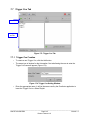
7.7 TRIGGER CUE TAB.................................................................................................................135
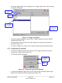
7.7.1 Trigger Cue Creation................................................................................................135
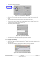
7.7.2 Connection to an Event............................................................................................136
7.7.3 Trigger Cue Saving..................................................................................................137
7.8 PRE-DEFINED MACRO USAGE..................................................................................................138
7.9 DEFAULT CUES.....................................................................................................................138
7.10 STARTUP SCRIPTS................................................................................................................138
____________________________________________________________________________________
D2K.DP.001659.DRM
Page 4
Version 1.2
Doremi Cinema LLC
8 NOTIFICATION ENGINE......................................................................................................139
8.1 GRAPHICAL NOTIFICATION........................................................................................................139
8.2 LOGS HANDLED BY THE GUI....................................................................................................141
8.3 RAID STATUS......................................................................................................................141
8.4 HARD DISK STATUS...............................................................................................................141
8.5 MEMORY STATUS...................................................................................................................143
8.6 SENSOR STATUS....................................................................................................................143
8.7 RAID MAINTENANCE .............................................................................................................144
8.8 SOFTWARE INTEGRITY.............................................................................................................145
8.9 DISK SPACE QUOTA...............................................................................................................145
8.10 NTP CLIENT STATUS...........................................................................................................146
9 UPDATING THE SOFTWARE AND FIRMWARE ...............................................................147
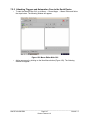
9.1 DISPLAYING THE SOFTWARE AND FIRMWARE VERSIONS...................................................................147
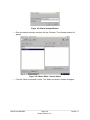
9.2 UPDATING THE SOFTWARE VIA USB..........................................................................................147
9.3 INGESTING THE DLM'S AND UPDATING THE SM SOFTWARE VIA USB..............................................149
9.3.1 Ingesting the DLM's via USB....................................................................................149
9.3.2 Updating the SM Version via USB............................................................................150
9.3.3 Updating the Dolphin Firmware Via USB..................................................................151
10 APPENDIX A: XML STRUCTURE USED BY MACRO EDITOR.......................................152
10.1 AUTOMATIONCUEMACROLIST SAMPLE......................................................................................152
10.2 AUTOMATIONCUEMACROLIST STRUCTURE................................................................................153
10.2.1 IssueDate Node.....................................................................................................154
10.2.2 Issuer Node............................................................................................................154
10.2.3 Creator Node.......................................................................................................... 154
10.2.4 AnnotationText Node..............................................................................................154
10.2.5 AutomationCueMacro Nodes.................................................................................155
10.2.5.1 Name Node......................................................................................................155
10.2.5.2 Id Node............................................................................................................. 155
10.2.5.3 AnnotationText Node (optional)........................................................................155
10.2.5.4 CommandList Node..........................................................................................155
10.2.6 Command Node (optional).....................................................................................155
10.2.6.1 Type Sub-Node................................................................................................156
10.2.6.2 Duration Sub-Node (optional)...........................................................................157
10.2.6.3 Line Sub-Node (optional)..................................................................................157
10.2.6.4 Value Sub-Node (optional)...............................................................................157
10.2.6.5 PulseDelay Sub-Node (optional)......................................................................157
10.2.6.6 DeviceName Sub-Node (optional)....................................................................158
10.2.6.7 MessageType Sub-Node (optional)..................................................................158
10.2.6.8 Message Sub-Node (optional)..........................................................................158
10.2.7 TriggerCue Node (optional)....................................................................................158
10.2.7.1 Name Node......................................................................................................158
10.2.7.2 ID Node............................................................................................................ 158
10.2.7.3 AnnotationText Node (optional)........................................................................159
10.2.7.4 CueType Node (optional).................................................................................159
10.2.7.5 CueTypeParameters (optional).........................................................................159
10.3 SCHEMA............................................................................................................................160
10.4 XML DIAGRAM LEGEND.......................................................................................................162
10.4.1 Element Symbols...................................................................................................162
10.4.1.1 Examples......................................................................................................... 162
____________________________________________________________________________________
D2K.DP.001659.DRM
Page 5
Version 1.2
Doremi Cinema LLC
10.4.2 Model Symbols ("compositors")..............................................................................163
10.5 TYPES...............................................................................................................................163
10.6 MODEL GROUPS AND REFERENCES..........................................................................................164
11 ANNEX B: NETMAP CONFIGURATION FILE..................................................................165
11.1 OVERVIEW..........................................................................................................................165
11.2 NETMAP FILE STRUCTURE......................................................................................................165
11.3 SAMPLE NETMAP FILE...........................................................................................................167
11.4 KNOWN ISSUES....................................................................................................................167
12 ANNEX C: TROUBLESHOOTING....................................................................................168
12.1 BIOS SETTINGS.................................................................................................................168
12.1.1 Doremi BIOS Setting (SuperMicro X7SBE)...........................................................168
12.2 SERVER LCD SCREEN MAINTENANCE......................................................................................169
12.2.1 Root Logging.......................................................................................................... 169
13 LINUX TERMINAL COMMANDS.......................................................................................170
13.1 LINUX LOG IN AND TERMINAL WINDOW (LOCAL CONNECTION).......................................................170
13.2 LINUX LOG IN AND TERMINAL WINDOW (REMOTE CONNECTION)....................................................170
13.2.1 Remote Log in From a Linux Computer..................................................................170
13.2.2 Remote Log in From a Windows PC......................................................................171
13.3 GENERATING DETAILED REPORTS............................................................................................171
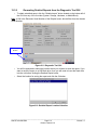
13.3.1 Generating Detailed Reports from Remote Access................................................171
13.3.1.1 Upload the File to a USB..................................................................................171
13.3.2 Generating Detailed Reports from the Diagnostic Tool GUI...................................172
13.4 SOFTWARE AND FIRMWARE UPDATE........................................................................................174
13.4.1 Transfer a Software Package to the Server Using FTP..........................................174
13.4.2 Performing the Software Upgrade..........................................................................174
13.4.3 Transfer a Firmware Package to the Server Using FTP.........................................174
13.5 INGEST FROM ETHERNET (FTP SERVER)................................................................................175
13.5.1 Uploading Files to a Remote Server via FTP.........................................................175
13.6 CHANGING THE LINUX LOG IN PASSWORD.................................................................................175
14 ACRONYMS....................................................................................................................... 176
15 DOCUMENT REVISION HISTORY....................................................................................177
____________________________________________________________________________________
D2K.DP.001659.DRM
Page 6
Version 1.2
Doremi Cinema LLC
Software License Agreement
The software license agreement can be found at the following location:
http://www.doremilabs.com/support/cinema-support/cinema-warranties/
Hardware Warranty
The hardware warranty can be found at the following location:
http://www.doremilabs.com/support/cinema-support/cinema-warranties/
____________________________________________________________________________________
D2K.DP.001659.DRM
Page 7
Version 1.2
Doremi Cinema LLC
WARNING
THIS DEVICE MUST BE GROUNDED.
IMPORTANT
Power requirements for electrical equipment vary from area to area. Please ensure that the
DCP-2000 or DCP-2K4 meet the power requirements in the surrounding area. If in doubt,
consult a qualified electrician or a Doremi Labs dealer.
DCP-2000 and DCP-2K4 Power Ratings
•
•
AC Input: 100-240V~, 6-3A, 60-50Hz
Maximum Power Consumption: 300W
WARNING: MULTIPLE SOURCES OF SUPPLY; DISCONNECT ALL SOURCES BEFORE
SERVICING.
DCP-2000 and DCP-2K4 Rack Mount and Thermal Information
•
•
•
•
Maximum operating ambient temperature is 35°C or 95°F.
Never restrict the air flow through the devices’ fan or vents.
When installing equipment into a rack, distribute the units evenly. Otherwise hazardous
conditions may be created by an uneven weight distribution.
Connect the unit only to a properly rated supply circuit. Reliable earthing (grounding) of
rack-mounted equipment should be maintained
PROTECTING YOURSELF AND THE DCP-2000 or DCP-2K4
Never touch the AC plug with wet hands. Always disconnect the DCP-2000 or DCP-2K4 from
the power supply by pulling on the plug not the cord. Allow only a Doremi Labs, Inc. dealer or
qualified professional engineer to repair or re-assemble the DCP-2000 or DCP-2K4. Apart from
voiding the warranty, unauthorized engineers might touch live internal parts and receive a
serious electric shock. Do not put, or allow anyone to put any object, especially metal objects,
into the DCP-2000 or DCP-2K4. Use only an AC power supply. Never use a DC power supply.
If water or any other liquid is spilled into or onto the DCP-2000 or DCP-2K4, disconnect the
power and call a Doremi dealer. The unit must be well ventilated and away from direct sunlight.
To avoid damage to internal circuitry, as well as the external finish, keep the DCP-2000 or DCP2K4 away from direct sources of heat (heater vents, stoves, radiators). Avoid using flammable
aerosols near the DCP-2000 or DCP-2K4. They can damage the surface area and may ignite.
Do not use denatured alcohol, paint thinner, or similar chemicals to clean the DCP-2000 or
DCP-2K4. This can damage the unit.
____________________________________________________________________________________
D2K.DP.001659.DRM
Page 8
Version 1.2
Doremi Cinema LLC
Modification of this equipment is dangerous and can result in the functions of the DCP-2000 or
DCP-2K4 being impaired. Never attempt to modify the equipment in any way. In order to ensure
optimum performance of the DCP-2000 or DCP-2K4, select the setup location carefully and
make sure the equipment is used properly. Avoid setting up the DCP-2000 or DCP-2K4 in the
following locations:
•
•
•
•
•
In a humid or dusty environment.
In a room with poor ventilation.
On a surface which is not level.
Inside a moving vehicle where it will be subject to vibration.
In an extremely hot or cold environment.
Removable Drives Warning
Removal of the hot swappable hard drives allows access to pins and traces supplying power to
the hard drive backplane. This is considered an energy hazard. Removal of the hard drives
must be performed by a trained service specialist or by trained personnel. The equipment may
only be used in a restricted access area which is not accessible to the general public.
Caution
•
•
•
•
Battery is located on the motherboard.
Danger of explosion if battery is incorrectly replaced.
Replace only with the same or equivalent type recommended by the manufacturer.
Dispose of used batteries according to the manufacturer’s instructions.
____________________________________________________________________________________
D2K.DP.001659.DRM
Page 9
Version 1.2
Doremi Cinema LLC
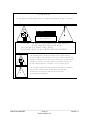
W A R N IN G !!
T o p re v e n t fire o r s h o c k h a z a rd , d o n o t e x p o s e th is a p p lia n c e to ra in o r m o is tu re
C A U T IO N
R IS K O F E L E C T R IC S H O C K
D O N OT O PEN
!
C A U T IO N :
T O R E D U C E T H E R IS K O F E L E C T R IC S H O C K ,
D O N O T R E M O V E C O V E R (O R B A C K ).
N O U S E R -S E R V IC E A B L E P A R T S IN S ID E .
R E F E R S E R V IC IN G T O Q U A L IF IE D S E R V IC E P E R S O N N E L .
T h e lig h tn in g fla s h w ith th e a rro w h e a d s y m b o l s u p e rim p o s e d
a c ro s s a g ra p h ic a l re p re s e n ta tio n o f a p e rs o n , w ith in a n e q u ila te ra l
tria n g le , is in te n d e d to a le rt th e u s e r to th e p re s e n c e o f u n in s u la te d
“ d a n g e ro u s v o lta g e ” w ith in th e p ro d u c t’s e n c lo s u re ; th a t m a y b e
o f s u ffic ie n t m a g n itu d e to c o n s titu te a ris k o f e le c tric s h o c k .
!
T h e e x c la m a tio n p o in t w ith in a n e q u ila te ra l tria n g le is in te n d e d to
a le rt th e u s e r to th e p re s e n c e o f im p o rta n t o p e ra tin g a n d
m a in te n a n c e (s e rv ic in g ) in s tru c tio n s in th e lite ra tu re
a c c o m p a n y in g th e a p p lia n c e .
____________________________________________________________________________________
D2K.DP.001659.DRM
Page 10
Version 1.2
Doremi Cinema LLC
CE NOTICE
Marking by the symbol
indicates compliance of the device to the EMC (Electromagnetic
Compatibility) directive and to the Low Voltage directive of the European Community. The
marking is indicative that the device meets or exceeds the following technical standards:
•
EN 55022 "Limits and Methods of Measurement of Radio Interface Characteristics of
Information Technology Equipment."
•
A "Declaration of Conformity" in accordance with the above standard has been made
and is on file at Doremi.
____________________________________________________________________________________
D2K.DP.001659.DRM
Page 11
Version 1.2
Doremi Cinema LLC
1 Introduction
1.1 Purpose
This manual is designed to guide the user through the installation and configuration of the DCP2000 or DCP-2K4. It also contains information on how to properly configure the unit to the
desired settings.
1.2 Software Version
•
This manual is intended for use with software version 2.0.10 and higher.
1.3 Contact
If in need of help or assistance, please contact Doremi Labs Technical Support at:
USA
• 24/7 Technical Support line: +1-866-484-4004
• Technical Support Email: [email protected]
Europe
• 24/7 Technical Support line: +33 (0) 492-952-847
• Technical Support Link: http://support.doremitechno.org/ticketing
Japan
• Technical Support line: +044-966-4855
• Technical Support Email: [email protected]
Australia ~ China ~ India ~ Indonesia ~ Korea ~ Malaysia ~ New Zealand ~ Philippines ~
Singapore ~ Taiwan ~ Thailand
• Technical Support Email: [email protected]
____________________________________________________________________________________
D2K.DP.001659.DRM
Page 12
Version 1.2
Doremi Cinema LLC
1.4 Drives Insertion
1.4.1 General Rules
•
In all cases do not insert or remove drives if the unit is powered on.
•
Drives are to be of the same make and model, and have the same capacity.
•
Doremi prohibits mixing SATA I drives with SATA II drives within the same RAID.
1.4.2 HDD Shipment
•
Hard disk drives (HDD) must be shipped out of the chassis. In this case, insert them in
before plugging in the power cables according to the procedure presented below:
•
Identify the label written on each HDD.
•
There will be one HDD with "A," one HDD with "B," and one HDD with "C" written on
them (Figure 1).
HDD Label
Location
Figure 1: HDD Label Location With “A” Label
•
For each HDD, press on the blue button located on the front side to release the gray
handle.
•
Open the gray handle all the way until it clicks ( Figure 2).
____________________________________________________________________________________
D2K.DP.001659.DRM
Page 13
Version 1.2
Doremi Cinema LLC
Gray Handle
Blue
Button
Figure 2: HDD Gray Handle Opened
•
Open the door covering the HDD case, which is located on the right side of the front
panel.
•
The drives can be inserted in any order.
•
The gray handle must remain open all the way.
A
LCD monitor
B
C
Figure 3:
HDD Location
____________________________________________________________________________________
D2K.DP.001659.DRM
Page 14
Version 1.2
Doremi Cinema LLC
•
Close the gray handle by pushing it toward the HDD until it clicks.
•
Power cables can now be plugged safely into the DCP-2000 or DCP-2K4.
1.5 Proper Power Off
Follow the instructions below to power off the DCP-2000 or DCP-2K4 safely. Any other method
might damage the RAID and result in RAID failure.
•
Select Shut Down from the "Logout" menu: Menu → Logout... → Shutdown.
•
Another method to power off the unit is to press and release the power button.
• To turn the unit back on, press and release the power switch.
Note: Do not press and hold the power Off button for more than a second.
____________________________________________________________________________________
D2K.DP.001659.DRM
Page 15
Version 1.2
Doremi Cinema LLC
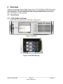
2 Overview
Thank you for choosing a Doremi Digital Cinema Server. The DCP-2000 and DCP-2K4 are high
quality DCI JPEG-2000 servers capable of playing movie or trailer packages in MXF format at
up to 250Mbits/sec. The DCP-2000 and DCP-2K4 also support MPEG2 Interop movies, preshow, and alternative content playback.
2.1 Front Panel
2.1.1 DCP-2000 Front Panel
• A DCP-2000 front panel with an LCD screen is shown below:
Figure 4: DCP-2000
Figure 5: DCP-2000 HDD Cage
____________________________________________________________________________________
D2K.DP.001659.DRM
Page 16
Version 1.2
Doremi Cinema LLC
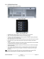
2.1.2 DCP-2K4 Front Panel
• A DCP-2K4 front panel is shown below:
Figure 6: DCP-2K4
Figure 7: DCP-2K4 HDD Cage
•
POWER (PWR): The LED lights turn green when the unit is powered on.
•
HDD: The Red LED light indicates access to the hard disk drives.
•
The door on the right on both types of units covers the "POWER" switch and the hard
disks that make up the RAID5 storage.
•
Each hard disk drive has a blue button that allows removal of the drive from the chassis.
•
Be careful NOT to remove the hard disk drive while the DCP-2000 or DCP-2K4 is
running.
•
There is one USB 2.0 connector on the center of the front panel that can accommodate
an external hard drive as well as a mouse or keyboard.
•
The left side of the front panel contains an LCD screen (only on units that are quipped
with a touchscreen).
•
On the panel, the LCD can be turned on or off by pressing on the LCD power button
using the stylus attached to the front panel. This button is located behind the stylus
(Figure 4).
Note: The use of the front panel LCD touchscreen requires that the two rear panel VGA
connectors are linked using the VGA cable provided with the DCP-2000 only.
____________________________________________________________________________________
D2K.DP.001659.DRM
Page 17
Version 1.2
Doremi Cinema LLC
2.2
Rear Panels
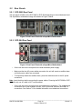
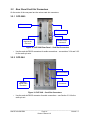
2.2.1 DCP-2000 Rear Panel
The rear panel will differ on the DCP-2000 or DCP-2K4 depending on the motherboard used.
The SuperMicro motherboard usage is illustrated in Figure 8 below.
Figure 8: Rear Panel Fitted with a SuperMicro Motherboard
2.2.2 DCP-2K4 Rear Panel
Figure 9: Rear Panel Fitted with a SuperMicro Motherboard
•
On the left side on the rear panel is the dual-redundant power supply.
•
Make sure that two AC power cables are used or the unit will sound an audible alarm
until both power cables are connected.
•
To temporarily disable the audible alarm, press the red button next to the AC power
connectors.
Note: Insert the drives before connecting the power cables. Powering the DCP-2000 or DCP2K4 with only one AC cable is NOT recommended.
•
On the left side on the rear panel are the motherboard connections. The motherboard
connections are for the keyboard, mouse, VGA, 9-pin serial, Ethernet and USB 2.0
connections. See Section 3.3 for detailed information on motherboard connections.
____________________________________________________________________________________
D2K.DP.001659.DRM
Page 18
Version 1.2
Doremi Cinema LLC
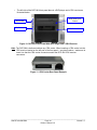
•
The left side of the DCP-2K4 front panel there is a DVD player and a CRU receiver as
illustrated below:
DVD ROM “Eject”
Button
DVD ROM
CRU Receiver
CRU Power Button
Figure 10: DCP-2K4 Front Panel With DVD Player and a CRU Receiver
Note: The DCP-2K4 is delivered without any CRU carrier. When inserting a CRU carrier into the
CRU receiver located on the left part of the front panel – see picture above - make sure to
insert it so that the CRU carrier connectors match the DCP-2K4 CRU receiver
connectors.
Figure 11: CRU Carrier Rear Panel Example
____________________________________________________________________________________
D2K.DP.001659.DRM
Page 19
Version 1.2
Doremi Cinema LLC
3 Rear Panel Connectors
3.1 VGA Cable Connection for Server LCD Screen Usage
If the front panel LCD touchscreen needs to be used, the server LCD touchscreen VGA
connector has to be linked to the motherboard VGA connector using the VGA cable. It is
provided with the DCP-2000. The VGA cable has to be secured to the DCP-2000 VGA
connectors using the integrated screws. If an external monitor is being used, then the VGA
cable should be attached to the lower VGA connector.
Server LCD
Screen
VGA connector
Motherboard VGA
connector
Figure 12: DCP-2000 Rear Panel with SuperMicro Motherboard VGA Connector
VGA cable required to link
the two rear panel VGA
connectors
Figure 13: VGA Cable
•
The rear panel is illustrated in Figure 14 below. The DCP-2K4 uses the same type of
VGA cable as the DCP-2000 to connect to an external monitor.
Red button
Power supply modules power switches
Figure 14: DCP-2K4 Rear Panel with SuperMicro Motherboard VGA Connector
____________________________________________________________________________________
D2K.DP.001659.DRM
Page 20
Version 1.2
Doremi Cinema LLC
3.2
Rear Panel Card Slot Connectors
On the center of the rear panel are the various card slot connectors.
3.2.1 DCP-2000
VGA connector
GPIO connector
AES/EBU
digital audio
connector
HD-SDI Output
connectors
Figure 15: DCP-2000 Rear Panel – Card Slot Connectors
•
Use the card slot DB-25 connectors for audio connections – see sections 3.2.4 and 3.2.5
for the audio pin-outs.
3.2.2 DCP-2K4
GPIO Connector
AES/EBU
Digital Audio
Connector
HD-SDI
Connectors
Figure 16: DCP-2K4 – Card Slot Connectors
•
Use the card slot DB-25 connector for audio connections – see Section 3.2.4 for the
audio pin-out.
____________________________________________________________________________________
D2K.DP.001659.DRM
Page 21
Version 1.2
Doremi Cinema LLC
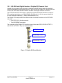
3.2.3 HD-SDI Serial Digital Interface / Dolphin DCI Decoder Card
Located in the rear panel card slots next to the digital audio AES output card is the standarddefinition/high-definition serial digital interface. This is the Doremi Dolphin DCI decoder card that
contains the JPEG-2000 decoder hardware and BNC serial digital interface connectors.
The DCP-2000 and DCP-2K4 utilizes a dual-link encrypted serial digital interface for output of
DCI-compliant resolutions up to 2048x1080p24 (2K-resolution). It can also operate single-link
for lower resolution material (e.g., trailers, advertisements, etc.).
The Dolphin DCI board provides two different kinds of external connectors on the DCP-2000
rear panel:
•
One GPIO (DVI-I) female connector
•
Two HD-SDI BNC connectors
The connectors of the Dolphin DCI board from top to bottom are GPIO, HD-SDI OUTPUT A,
and HD-SDI OUTPUT B. They are illustrated below:
GPIO Connector
HD-SDI Output - Link A
HD-SDI Output - Link B
Figure 17: Dolphin DCI Board Bracket
____________________________________________________________________________________
D2K.DP.001659.DRM
Page 22
Version 1.2
Doremi Cinema LLC
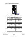
•
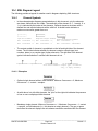
The GPIO DVI-I connector pin numbering is illustrated below:
17
18
19
20
21
22
23
24
9
10
11
12
13
14
15
16
1
2
3
4
5
6
7
8
C3
C1
C4
C2
C5 / C6
Figure 18: Dolphin DCI GPIO (DVI-I) Female Connector
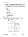
•
The General Purpose I/O DVI-I connector pin-out follows:
GPIO (DVI-I) Female Connector
Pin #
Signal Description
Pin
#
Signal Description
1
GPO 3
16
GPI 2-
2
GPO 2
17
GPO 7
3
GND (ground)
18
GPO 6
4
N/C
19
GND (ground)
5
N/C
20
GPO 1
6
GPI 5-
21
GPO 0
7
GPI 3-
22
GPI 5+
8
GPI 2+
23
GPI 4+
9
GPO 5
24
GPI 3+
10
GPO 4
C1
GPI 1-
11
GND (ground)
C2
GPI 0-
12
N/C
C3
GPI 1+
13
N/C
C4
GPI 0+
14
5V / 0.2A
C5/C
6
GND (ground)
15
GPI 4-
____________________________________________________________________________________
D2K.DP.001659.DRM
Page 23
Version 1.2
Doremi Cinema LLC
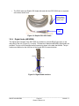
•
The GPIO cable and Dolphin DCI board delivered with the DCP-2000 have an exposed
wire end as shown here:
Connector to be
plugged into the
DCP-2000 GPIO
adapter cable
Un-wired
end
Figure 19: Dolphin DCI GPIO Cable
3.2.4
Digital Audio (AES/EBU)
The digital audio interface of the DCP-2000 is provided on a female DB-25 connector on the
rear panel of the unit (Figure 15). Currently, 16 channels of balanced AES/EBU digital audio are
provided. The pin-out for the digital audio connector is shown in the table that follows. The pin
numbers are defined on the front face of the female DB-25 connector below:
Pin 25
Pin 13
Pin 2
Pin 14
Pin 1
Figure 20: Digital Audio Interface
____________________________________________________________________________________
D2K.DP.001659.DRM
Page 24
Version 1.2
Doremi Cinema LLC
•
The AES/EBU digital audio DB-25 connector pin-out follows:
DCI Channel Map:
Channel 1:
Channel 2:
Channel 3:
Channel 4:
Channel 5:
Channel 6:
Channel 7:
Channel 8:
L (screen – left)
R (screen – right)
C (screen – center)
LFE (screen – low frequency effects
subwoofer)
Ls (surround – left wall)
Rs (surround – right wall)
Lc (screen – mid left to center)
Rc (screen – mid right to center)
Pin #
Signal Description
Pin #
Signal Description
1
Ch 15 & 16 plus
14
Ch 15 & 16 minus
2
Ch 15 & 16 ground
15
Ch 13 & 14 plus
3
Ch 13 & 14 minus
16
Ch 13 & 14 ground
4
Ch 11 & 12 plus
17
Ch 11 & 12 minus
5
Ch 11 & 12 ground
18
Ch 9 & 10 plus
6
Ch 9 & 10 minus
19
Ch 9 & 10 ground
7
Ch 7 & 8 plus
20
Ch 7 & 8 minus
8
Ch 7 & 8 ground
21
Ch 5 & 6 plus
9
Ch 5 & 6 minus
22
Ch 5 & 6 ground
10
Ch 3 & 4 plus
23
Ch 3 & 4 minus
11
Ch 3 & 4 ground
24
Ch 1 & 2 plus
12
Ch 1 & 2 minus
25
Ch 1 & 2 ground
13
no connection
____________________________________________________________________________________
D2K.DP.001659.DRM
Page 25
Version 1.2
Doremi Cinema LLC
3.2.5 Analog Audio
The analog audio interface is available by purchasing a Doremi AUD-D2A external digital to
analog audio converter.
3.3 Motherboard Connections
3.3.1 Motherboard Connectors
On the rear panel of both the units are the connections to the motherboard. The motherboard
used on the DCP-2000 and DCP-2K4 is a SuperMicro.
3.3.1.1
SuperMicro Motherboard Connectors
Mouse
Ethernet
1
Keyboard
USB
Ports
Serial
Port
VGA Port
Ethernet
0
Figure 21: Rear Panel SuperMicro Motherboard Connectors
3.3.2 Keyboard and Mouse PS-2 Connectors
On the left side of the connector panel are the PS-2 connectors for the PC keyboard and
mouse. These jacks can be used interchangeably, but traditionally the purple jack is for a PC
keyboard and the green jack is for a PS-2 mouse. If the user has a USB keyboard or mouse,
then use the USB ports on the left side of the motherboard connector panel.
3.3.3 Serial Port
This is a standard 9-pin male DB-9 serial COM port on the motherboard.
3.3.4 VGA
Connect a standard VGA monitor to display the DCP-2000 or DCP-2K4 software interface.
This connector can also be linked to the center rear panel VGA connector to facilitate use of the
front panel LCD screen (only DCP-2000 units). The VGA cable is provided with the DCP-2000
and DCP-2K4.
3.3.5 USB Ports
Connect standard USB 2.0 peripherals for a PC USB keyboard, mouse, hard drive, etc.
3.3.6 Ethernet
The motherboard has two built-in Gigabit Ethernet connectors. The left one is identified as
"Eth0" and the right one is identified as "Eth1."
____________________________________________________________________________________
D2K.DP.001659.DRM
Page 26
Version 1.2
Doremi Cinema LLC
4 Network Configuration
4.1 Default Network Configuration
All servers are shipped with a default IP address of 192.168.100.50 on the Ethernet port (Eth1)
and a DHCP assigned dynamic IP address on the Ethernet port (Eth0).
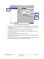
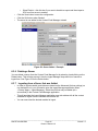
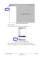
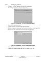
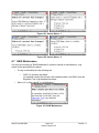
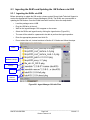
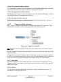
4.2 Changing the IP Address
•
To change the IP address of the server, select Menu → System → Networking
Configuration and then follow the steps below:
•
A window will appear asking for a password as illustrated below:
Figure 22: Password Confirmation Window
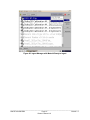
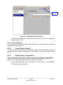
•
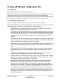
Follow the steps according to the "Ethernet Networking Configuration" Wizard.
Figure 23: Network Configuration
•
Press Enter to confirm the configuration of each page of the "Ethernet Networking
Configuration" Wizard. Press "Tab" to select an option.
•
Enter the desired system’s hostname and then press Enter (Note: It is a good idea to put
the circuit location/screen number in here. For example, “AMC_bir_scr1,” as it will be
easier to identify when connecting via VNC and in the logs).
•
Enter the desired system domain name and then press Enter.
•
Select Yes to set eth0 and then press Enter.
•
Select No for Removable Device and then press Enter.
•
Select No for automatically configure device with DHCP and then press Enter.
•
Enter the desired IP address for eth0 and then press Enter.
____________________________________________________________________________________
D2K.DP.001659.DRM
Page 27
Version 1.2
Doremi Cinema LLC
•
Enter the desired default gateway or leave empty and then press Enter.
•
Enter the desired subnet mask and then press Enter.
•
Select Yes to configure eth1 and then press Enter.
•
Select No for Removable device and then press Enter.
•
Select No for automatically configure device with DHCP and then press Enter.
•
Enter the IP address of eth1 and select OK – in the example, enter 192.168.100.50 and
then press Enter.
Note: Do not put leading zeros (0) in front of any numbers. For example, do not input
0192.168.100.50.
•
Enter the desired default gateway or leave empty and then press Enter.
•
Enter the desired subnet mask and select OK – in our example, enter the same subnet
mask as the projector: 255.255.255.0 and then press Enter.
•
Enter the IP Address of the System's Domain Name Server (or leave empty) and then
press Enter to exit the wizard.
•
To verify the setup, go to Menu → Doremi Apps. → Diagnostic Tool and verify the IP
Address under the Diagnostic Tool System Tab.
4.3 Network Restart
If for any reason the network needs to be restarted, use the terminal command line below:
• Type: /etc/init.d/networking restart <Enter>
____________________________________________________________________________________
D2K.DP.001659.DRM
Page 28
Version 1.2
Doremi Cinema LLC
5 Time Zone Configuration
Units are by default set to Pacific Time Zone (PST or PDT). This section provides information on
how to check and/or change the time zone.
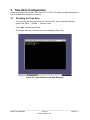
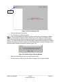
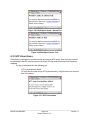
5.1
Checking the Time Zone
•
To confirm that the time zone of the unit is set correctly, open a terminal window by
going to the “Menu → System → Terminal” menu.
•
Type: date and then press Enter.
•
The current date, time, and time zone will be displayed (Figure 24).
Figure 24: Terminal Window with Date Displayed
____________________________________________________________________________________
D2K.DP.001659.DRM
Page 29
Version 1.2
Doremi Cinema LLC
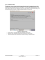
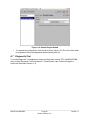
5.2
Changing the Time Zone
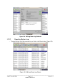
•
To change the time zone, follow the steps below in the terminal window
(Menu/System/Terminal):
•
Type: su and then press Enter.
•
Type the "root" password to log in as "root" – consult the system administrator to receive
the root password or Doremi to know the default root password.
•
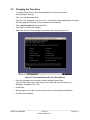
Type: rwdo tzconfig and then press Enter.
•
Type: Yes (to confirm the change).
•
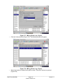
Select the number of the geographic area for the time change (Figure 25).
Figure 25: Terminal Window with Time Zone Wizard
•
Once the geographic area number has been selected, press Enter.
•
Type the name of the city / region that you would like the time zone set to (e.g.,
Singapore, Caribbean, PST, etc.).
•
Press Enter.
•
After typing the city / region, the unit will now be set to the desired configuration.
•
Exit the terminal window.
____________________________________________________________________________________
D2K.DP.001659.DRM
Page 30
Version 1.2
Doremi Cinema LLC
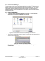
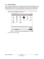
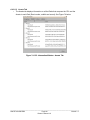
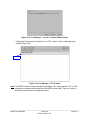
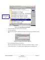
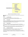
6 Control Panel
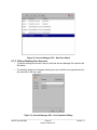
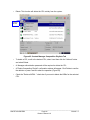
•
•
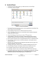
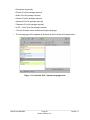
To access the Control Panel window, go to Menu and click on Control Panel.
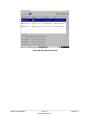
The following window will appear:
Figure 26: Control Panel Window
•
The Control Panel window provides access to various applications as listed below: See
Figure 26 above for more information.
1. Account Manager: Allows the user to add/remove/edit user accounts.
2. Audio Configuration: Allows the user to route all audio tracks to operator-designated
outputs (only SMPTE content).
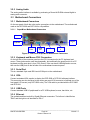
3. Content Feed Manager: Allows the user to add an FTP ingest server.
4. Content Manager: Allows the user to browse, manage and export all the content
available on the player including: ShowPlaylists, CPLs, KDMs and Doremi Licenses.
5. Device Controller: Allows the user to create/edit/register devices in a simplified manner.
6. Device Manager: Allows the user to add different projectors, close caption devices,
subtitle devices, etc.
7. Diagnostic Tool: Provides the user with Diagnostic information about the system. See
document “Diagnostic Tool User Guide.”
8. Language Setup window: Allows the user to change the language used on the unit.
9. License Manager: Displays and manages software licenses installed on the unit.
10. Live Manager: Allows the user to create a device as source of live events.
11. Log Manager: Allows the user to automatically configure SMPTE and System logs.
12. Log Operator Maintenance: Allows the user to log important information (e.g., hard disk
replacement, projector lamp replacement, etc.). This application helps the system
administrator keep track of any change operated in a theater booth.
____________________________________________________________________________________
D2K.DP.001659.DRM
Page 31
Version 1.2
Doremi Cinema LLC
13. Network Configuration: Set up and modify network connections.
14. Time Setting: Due to DCI requirements, users can only set the time to no more than 30
minutes per calendar year on a Dolphin DCI FIPS 1.0 board. For Dolphin DCI FIPS 1.2
boards, you can only adjust the RTC (Real Time Clock) time within DCI allowed-time of
6 minutes per calendar year.
15. Touch Screen Calibration: Initiates the touch screen calibration process (only applicable
to models with a touchscreen).
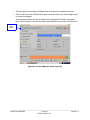
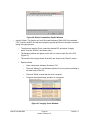
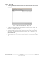
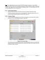
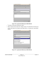
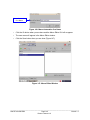
6.1 Account Manager GUI
•
To access the Account Manager GUI, double-click on the Account Manager icon within
the Control Panel window or select it and click the Start” button located on the rightbottom side of the Control Panel window.
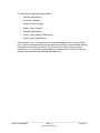
•
Input the appropriate password to continue and press the Ok button.
Figure 27: Password Confirmation Window
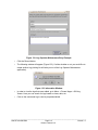
•
The following window will appear:
Figure 28: Account Manager GUI
____________________________________________________________________________________
D2K.DP.001659.DRM
Page 32
Version 1.2
Doremi Cinema LLC
•
The Account Manager GUI allows the user to edit, add, and delete user accounts (Figure
28).
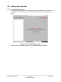
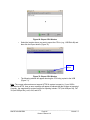
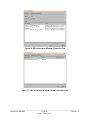
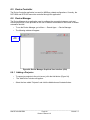
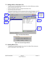
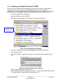
6.1.1 Add a New User Account
•
To add a new user account, click the Add button (Figure 28).
•
The following window will appear:
Figure 29: Account Manager GUI – New User Addition
•
Enter the username (to be used for log in) in the upper empty field and the associated
“Full Name” used to describe the user. Both names will be displayed in the Control Panel
window after the new user addition is completed.
•
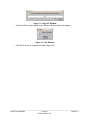
Define the password by clicking the “Set Password” button.
•
The following window will appear:
Figure 30: Password Definition Window
Note: The user will be provided information about the strength of the chosen password. Click
the “Set” button when the appropriate password is defined. Confirm the password in the
“Confirm” field. The user privileges need to be defined using the list-box.
•
Click the Set button to save the new password.
____________________________________________________________________________________
D2K.DP.001659.DRM
Page 33
Version 1.2
Doremi Cinema LLC
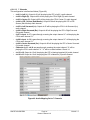
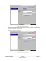
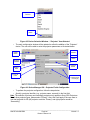
•
Select the proper privileges. They are listed below from the lowest level to the highest
level of privileges:
1) Projectionist: Projectionist is a standard user allowed to use the Doremi applications
present on the unit without changing the configuration.
2) Show Manager: In addition to Projectionist's privileges, a Show Manager user is allowed
to ingest and delete content.
3) SuperUser: In addition to Show Manager's right, a SuperUser has the privileges to
configure the unit. For example, the SuperUser can update the firmware and software.
4) Administrator: An Administrator user will be a user in the group of “root.” The
Administrator can perform all of the privileges listed above in addition to creating,
modifying, and deleting user accounts.
Figure 31: Account Manager GUI – Privileges Definition
•
Furthermore, two different log in types are available for the user:
1. Application: Virtual user account only works with Doremi applications.
2. System: Regular Linux user account that can be used anywhere on the system. For
example, on Linux terminal windows.
•
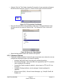
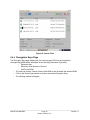
Select the proper user account type and click the Save button.
•
The new user account will be visible in the main Account Manager GUI as illustrated
below:
____________________________________________________________________________________
D2K.DP.001659.DRM
Page 34
Version 1.2
Doremi Cinema LLC
Figure 32: Account Manager GUI – New User Added
6.1.2 Edit an Existing User Account
•
To edit an existing user account, select it within the Account Manager GUI and click the
Edit button.
•
The following dialog box will appear allowing the user to edit the user properties but not
the username or the log in type.
Figure 33: Account Manager GUI – User Properties Editing
____________________________________________________________________________________
D2K.DP.001659.DRM
Page 35
Version 1.2
Doremi Cinema LLC
•
Click the Save button when finished editing the settings (Figure 33).
•
Click the Close button when finished with the configuration (Figure 33).
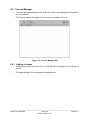
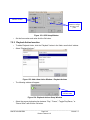
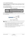
6.1.3 Delete an Existing User Account
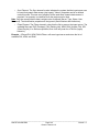
•
To delete an existing user account, select it within the main Account Manager GUI and
click the Delete button.
•
The user will be asked for a confirmation. Clicking Yes will delete the user account.
Figure 34: User Account Deletion Confirmation
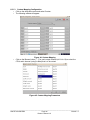
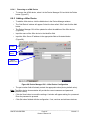
6.2 Audio Configuration
The Audio Configuration application allows the user to route all audio tracks in an
SMPTE/Interop package to operator-designated outputs. The main purpose of the mapping is to
allow users to move the HI or VI channels to a specific output. The Audio Configuration
application is available in the Control Panel.
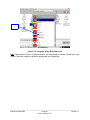
•
To open the Audio Configuration application, go to Menu -> Control Panel -> Audio
Configuration (Figure 35).
Figure 35: Control Panel with Audio Configuration Icon Selected
•
An “admin” password and confirmation will be needed to perform the operation.
•
The Audio Configuration window will appear.
____________________________________________________________________________________
D2K.DP.001659.DRM
Page 36
Version 1.2
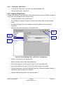
Doremi Cinema LLC
Template
Mapping
Save
Button
Advanced
Tab
Channel
Mapping
Tab
Figure 36: Audio Configuration - Default Setting
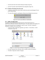
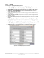
When first launched, the Audio Configuration application opens in the Channel Mapping
tab. The Template Mapping will be set to Disabled (Figure 36).
Note: All the templates, except “Disabled,” can be modified directly instead of having to select
“Custom.” Once the template is edited, the “Template Mapping” will read “Custom.”
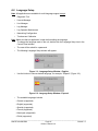
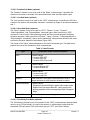
• Available configurations include:
• Disabled: This setting is the default and as such cannot be mapped (Section
6.2.1.1).
• 4 channels: This is a pre-set configuration.
• 6 channels: This is a pre-set configuration.
• 7 channels: This is a pre-set configuration.
• 8 channels: This is a pre-set configuration.
• 9 channels: This is a pre-set configuration.
• ISDCF: This is a pre-set configuration.
• Custom: This setting allows the user to create his/her own custom audio
configuration.
•
____________________________________________________________________________________
D2K.DP.001659.DRM
Page 37
Version 1.2
Doremi Cinema LLC
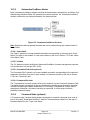
6.2.1 Channel Mapping Tab
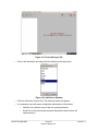
6.2.1.1
•
6.2.1.2
Disabled Configuration
Figure 37: Disabled Configuration
Disabled: This setting is the default and as such cannot be mapped. The Disabled
mapping configuration will perform pass-through mapping, meaning channel number "X"
of the CPL audio track will be routed to audio output number "X" (variable) of the server.
"X" being a number between 1 and 16. When the configuration is grayed-out, the user
cannot change the configuration.
Pre-Defined Mapping Configurations
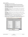
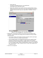
6.2.1.2.1 4 Channels
This configuration is defined as follows (Figure 38):
•
•
•
•
•
•
•
•
ch.01 is Left (L): Output ch.01 will be playing the CPL's Left (L) audio channel.
ch.02 is Right (R): Output ch.02 will be playing the CPL's Right (R) audio channel.
ch.03 is Center (C): Output ch.03 will be playing the CPL's Center (C) audio channel.
ch.04 is Input: ch.04 is pass-through, meaning the output channel “X” will be playing the
CPL's audio channel “X.”
ch.05 is Surround (S): Output ch.05 will be playing the CPL's Surround (S) audio
channel.
Channels ch.06 - ch.14 are pass-through, meaning the output channel “X” will be
playing the CPL's audio channel “X.” “X” will be a value between 6 and 14.
ch.15 is HI: Output ch.15 will be playing the CPL's Hearing Impaired (HI) audio channel.
ch.16 is VI: Output ch.16 will be playing the CPL's Narration (VI) audio channel.
____________________________________________________________________________________
D2K.DP.001659.DRM
Page 38
Version 1.2
Doremi Cinema LLC
Figure 38: Audio Mapping Set to 4 Channels
____________________________________________________________________________________
D2K.DP.001659.DRM
Page 39
Version 1.2
Doremi Cinema LLC
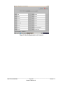
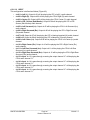
6.2.1.2.2 6 Channels
This configuration is defined as follows (Figure 39):
• ch.01 is Left (L): Output ch.01 will be playing the CPL's Left (L) audio channel.
• ch.02 is Right (R): Output ch.02 will be playing the CPL's Right (R) audio channel.
• ch.03 is Center (C): Output ch.03 will be playing the CPL's Center (C) audio channel.
• ch.04 is LFE / Screen (Sub-Woofer): Output ch.04 will be playing the CPL's LFE /
Screen (Sub-Woofer) audio channel.
• ch.05 is Left Surround (Ls): Output ch.05 will be playing the CPL's Left Surround (Ls)
audio channel.
• ch.06 is Right Surround (Rs): Output ch.06 will be playing the CPL's Right Surround
(Rs) audio channel.
•
Channels ch.07 - ch.14 are pass-through, meaning the output channel “X” will be
playing the CPL's audio channel “X.” “X” will be a value between 7 and 14.
•
ch.15 is HI: Output ch.15 will be playing the CPL's Hearing Impaired (HI) audio channel.
•
ch.16 is VI: Output ch.16 will be playing the CPL's Narration (VI) audio channel.
Figure 39: Audio Mapping Set to 6 Channels
____________________________________________________________________________________
D2K.DP.001659.DRM
Page 40
Version 1.2
Doremi Cinema LLC
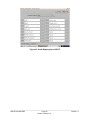
6.2.1.2.3 7 Channels
This configuration is defined as follows (Figure 40):
•
ch.01 is Left (L): Output ch.01 will be playing the CPL's Left (L) audio channel.
•
ch.02 is Right (R): Output ch.02 will be playing the CPL's Right (R) audio channel.
•
ch.03 is Center (C): Output ch.03 will be playing the CPL's Center (C) audio channel.
•
ch.04 is LFE / Screen (Sub-Woofer): Output ch.04 will be playing the CPL's LFE /
Screen (Sub-Woofer) audio channel.
•
ch.05 is Left Surround (Ls): Output ch.05 will be playing the CPL's Left Surround (Ls)
audio channel.
•
ch.06 is Right Surround (Rs): Output ch.06 will be playing the CPL's Right Surround
(Rs) audio channel.
ch.07 is Input: ch.07 is pass-through, meaning the output channel “X” will be playing the
CPL's audio channel “X.”
ch.08 is Input: ch.08 is pass-through, meaning the output channel “X” will be playing the
CPL's audio channel “X.”
ch.09 is Center Surround (Cs): Output ch.09 will be playing the CPL's Center Surround
(Cs) audio channel.
Channels ch.10 - ch.14 are pass-through, meaning the output channel “X” will be
playing the CPL's audio channel “X.” “X” will be a value between 10 and 14.
•
•
•
•
•
ch.15 is HI: Output ch.15 will be playing the CPL's Hearing Impaired (HI) audio channel.
•
ch.16 is VI: Output ch.16 will be playing the CPL's Narration (VI) audio channel.
Figure 40: Audio Mapping Set to 7 Channels
____________________________________________________________________________________
D2K.DP.001659.DRM
Page 41
Version 1.2
Doremi Cinema LLC
6.2.1.2.4 8 Channels
This configuration is defined as follows (Figure 41):
•
ch.01 is Left (L): Output ch.01 will be playing the CPL's Left (L) audio channel.
•
ch.02 is Right (R): Output ch.02 will be playing the CPL's Right (R) audio channel.
•
ch.03 is Center (C): Output ch.03 will be playing the CPL's Center (C) audio channel.
•
ch.04 is LFE / Screen (Sub-Woofer): Output ch.04 will be playing the CPL's LFE /
Screen (Sub-Woofer) audio channel.
•
ch.05 is Left Surround (Ls): Output ch.05 will be playing the CPL's Left Surround (Ls)
audio channel.
•
ch.06 is Right Surround (Rs): Output ch.06 will be playing the CPL's Right Surround
(Rs) audio channel.
ch.07 is Left Center (Lc): Output ch.07 will be playing the CPL's Left Center (Lc) audio
channel.
ch.08 is Right Center (Rc): Output ch.08 will be playing the CPL's Right Center (Rc)
audio channel.
Channels ch.9 - ch.14 are pass-through, meaning the output channel “X” will be playing
the CPL's audio channel “X.” “X” will be a value between 9 and 14.
•
•
•
•
ch.15 is HI: Output ch.15 will be playing the CPL's Hearing Impaired (HI) audio channel.
•
ch.16 is VI: Output ch.16 will be playing the CPL's Narration (VI) audio channel.
Figure 41: Audio Mapping Set to 8 Channels
____________________________________________________________________________________
D2K.DP.001659.DRM
Page 42
Version 1.2
Doremi Cinema LLC
6.2.1.2.5 9 Channels
This configuration is defined as follows (Figure 42):
•
ch.01 is Left (L): Output ch.01 will be playing the CPL's Left (L) audio channel.
•
ch.02 is Right (R): Output ch.02 will be playing the CPL's Right (R) audio channel.
•
ch.03 is Center (C): Output ch.03 will be playing the CPL's Center (C) audio channel.
•
ch.04 is LFE / Screen (Sub-Woofer): Output ch.04 will be playing the CPL's LFE /
Screen (Sub-Woofer) audio channel.
•
ch.05 is Left Surround (Ls): Output ch.05 will be playing the CPL's Left Surround (Ls)
audio channel.
•
ch.06 is Right Surround (Rs): Output ch.06 will be playing the CPL's Right Surround
(Rs) audio channel.
ch.07 is Left Center (Lc): Output ch.07 will be playing the CPL's Left Center (Lc) audio
channel.
•
•
•
ch.08 is Right Center (Rc): Output ch.08 will be playing the CPL's Right Center (Rc)
audio channel.
ch.09 is Center Surround (Cs): Output ch.09 will be playing the CPL's Center Surround
(Cs) audio channel.
•
Channels ch.10 - ch.14 are pass-through, meaning the output channel “X” will be
playing the CPL's audio channel “X.” “X” will be a value between 10 and 14.
•
ch.15 is HI: Output ch.15 will be playing the CPL's Hearing Impaired (HI) audio channel.
•
ch.16 is VI: Output ch.16 will be playing the CPL's Narration (VI) audio channel.
Figure 42: Audio Mapping Set to 9 Channels
____________________________________________________________________________________
D2K.DP.001659.DRM
Page 43
Version 1.2
Doremi Cinema LLC
6.2.1.2.6 ISDCF
This configuration is defined as follows (Figure 43):
•
ch.01 is Left (L): Output ch.01 will be playing the CPL's Left (L) audio channel.
•
ch.02 is Right (R): Output ch.02 will be playing the CPL's Right (R) audio channel.
•
ch.03 is Center (C): Output ch.03 will be playing the CPL's Center (C) audio channel.
•
ch.04 is LFE / Screen (Sub-Woofer): Output ch.04 will be playing the CPL's LFE /
Screen (Sub-Woofer) audio channel.
•
ch.05 is Left Surround (Ls): Output ch.05 will be playing the CPL's Left Surround (Ls)
audio channel.
•
ch.06 is Right Surround (Rs): Output ch.06 will be playing the CPL's Right Surround
(Rs) audio channel.
•
ch.07 is HI: Output ch.07 will be playing the CPL's Hearing Impaired (HI) audio channel.
•
ch.08 is VI: Output ch.08 will be playing the CPL's Narration (VI) audio channel.
ch.09 is Left Center (Lc): Output ch.09 will be playing the CPL's Left Center (Lc) audio
channel.
ch.10 is Right Center (Rc): Output ch.10 will be playing the CPL's Right Center (Rc)
audio channel.
ch.11 is Left Rear Surround (Lrs): Output ch.11 will be playing the CPL's Left Rear
Surround (Lrs) audio channel.
ch.12 is Right Rear Surround (Rrs): Output ch.12 will be playing the CPL's Right Rear
Surround (Rrs) audio channel.
ch.13 is Input: ch.13 is pass-through, meaning the output channel “X” will be playing the
CPL's audio channel “X.”
ch.14 is Input: ch.14 is pass-through, meaning the output channel “X” will be playing the
CPL's audio channel “X.”
ch.15 is Input: ch.15 is pass-through, meaning the output channel “X” will be playing the
CPL's audio channel “X.”
ch.16 is Input: ch.16 is pass-through, meaning the output channel “X” will be playing the
CPL's audio channel “X.”
•
•
•
•
•
•
•
•
____________________________________________________________________________________
D2K.DP.001659.DRM
Page 44
Version 1.2
Doremi Cinema LLC
Figure 43: Audio Mapping Set to ISDCF
____________________________________________________________________________________
D2K.DP.001659.DRM
Page 45
Version 1.2
Doremi Cinema LLC
6.2.1.3
Custom Mapping Configuration
•
•
Click on the drop-down menu and select Custom.
The following window will appear.
•
Figure 44: Custom Mapping
Click on the Browse button ("...") for each output channel (ch.01-ch.16) to select the
CPL's audio channel (using its label) that is to be routed.
Figure 45: Custom Mapping Parameters
____________________________________________________________________________________
D2K.DP.001659.DRM
Page 46
Version 1.2
Doremi Cinema LLC
6.2.2 Advanced Tab
This tab allows the user to add a delay between audio and video by dragging the cursor to the
desired delay. On the graphical cursor that allows values between -200 milliseconds and 200
milliseconds. All audio tracks will get the same delay. You cannot add separate delays for each
track. After the delay has been configured, click on the Save button to save the audio delay. The
selected audio delay is shown in numeric characters below the cursor field.
•
•
•
Figure 46: Advanced Tab
Positive Value: The audio will be heard behind the video action.
Negative Value: Indicates that the audio is ahead of the video action.
The recommended value that almost matches all setups is 80 milliseconds.
____________________________________________________________________________________
D2K.DP.001659.DRM
Page 47
Version 1.2
Doremi Cinema LLC
6.2.3 SMPTE Packages
Note: The audio selection should reflect the audio package in number of audio channels.
•
•
•
You can change the Template Mapping setting by clicking on the list-menu and selecting
the desired setting (Figure 37).
Make sure to click the Save button to ensure the configuration is saved (Figure 36).
The list of possible labels that can be routed (if present in the audio MXF file) are defined
by SMPTE as follows:
• L/Left
• R/Right
• C/Center
• LFE Screen
• Ls/Left surround
• Rs/Right surround
• Lc/Left center
• Rc/Right center
• Cs/Center surround
• Rrs/Right rear surround
• Lrs/Left rear surround
• HI/Hearing Impaired
• VI-N/Visual Impaired-Narration
6.2.4 Interop Packages
Interop audio MXF files do not contain any channel label information. Therefore, if a
configuration is selected, the routing will be executed as if the audio MXF file was created
according to the ISDCF audio mapping recommendations, which currently consists of:
Figure 47: ISDCF – Interop Recommendations
____________________________________________________________________________________
D2K.DP.001659.DRM
Page 48
Version 1.2
Doremi Cinema LLC
6.3 Content Feed Manager
The main purpose of the Content Feed Manager application is to add an FTP ingest source; in
addition, multiple units can be interconnected to share content simultaneously. The "Content
Feed Manager" makes the ingestion process quicker and simpler. This same procedure is
available in document "Content Feed Manager GUI User Manual," which is document number
D2K.OM.001597.DRM.
6.3.1 Quick Configuration
•
To open the Content Feed Manager application, go to Menu -> Control Panel and
double-click on the Content Feed Manager icon (Figure 48).
•
Figure 48: Control Panel with Content Feed Manager Icon Selected
You will need to authenticate yourself as "admin" by inputting the correct password to be
allowed to use this application.
•
Figure 49: Password Confirmation Window
When the Content Feed Manager is started for the first time, it will be appear as
illustrated below:
____________________________________________________________________________________
D2K.DP.001659.DRM
Page 49
Version 1.2
Doremi Cinema LLC
Figure 50: Content Feed Manager GUI
6.3.2 Scan for Server
•
Click the "Scan for Server" button to check and see if any servers are present on the
network. The following window will appear displaying the unit type, e-S/N, and IP as well
(Figure 51):
•
Qualifications for a server include: all DCP, ShowVaults, and TMS units that have an IP
address and are connected within the same networks with the concerned unit
(destination). The units can be used as sources for material.
•
Figure 51: Scan for Server Button
Scroll and select the server, then click the Add button (Figure 51). Once the server has
been selected the Content Feed Manager GUI will automatically be updated with the
default credentials.
____________________________________________________________________________________
D2K.DP.001659.DRM
Page 50
Version 1.2
Doremi Cinema LLC
Add
Button
Browse
Button
Advanced
Options
Button
Figure 52: Automatically Updated Server
•
The "Identifier" field identifies the server and can be renamed for the user's convenience.
•
The "Ingest Protocol" field allows the user to select the transfer protocol. Currently, only
FTP is supported.
•
Once the server is selected, the IP field will automatically be populated.
•
You can click on the "Test" button to determine if the unit is available in the network
once it has been selected.
•
Username and Password fields are for security purposes.
•
The "Remote Path" field is for the destination of the server. It is not needed when using
the "Scan for Server" method.
•
Click on the Save button to save this configuration for the Content Feed Manager. The
unit is now confirmed as an ingest source for our destination unit.
____________________________________________________________________________________
D2K.DP.001659.DRM
Page 51
Version 1.2
Doremi Cinema LLC
6.3.3 Advanced Options Button
Save
Button
Advanced
Options
Button
Figure 53: Advanced Options Menu
•
Clicking the "Advanced Options" button will open a drop-down menu where the user can
configure the following file types to be used for ingesting (Figure 53):
•
Authorize "play while ingest" from this server (enabled by default)
•
Key Delivery Message – allows the KDM to be ingested from the FTP or another
server registered in the netmap.
•
Composition Playlist (enabled by default) – allows import or FTP of a CPL into
the server.
•
Installation Package software, security manager, firmware packages for
upgrades.
•
Doremi License (DLM) – Doremi License Messages, e.g., Dolby3D, RealD, 4K
Enabled, etc.
•
Show Playlist – click this box if you want to be able to export and then import a
SPL from one server to another.
•
Click the Save button to save the configuration.
•
Click the Quit button when finished.
____________________________________________________________________________________
D2K.DP.001659.DRM
Page 52
Version 1.2
Doremi Cinema LLC
6.3.4 Adding a Server Manually
6.3.4.1
•
•
Networking the Server(s)
The Content Feed Manager GUI can be manually set up by clicking the Add button. This
will allow the user to add a new server for which the fields will have to be manually
entered.
Figure 54: Content Feed Manager GUI
Click the Add button to add a new server. The following window will appear:
____________________________________________________________________________________
D2K.DP.001659.DRM
Page 53
Version 1.2
Doremi Cinema LLC
Figure 55: Add New Server
•
Enter the Identifier name in the Identifier field. It is recommended that a unique identifier
be used (e.g., screen 1, screen 2, etc).
•
Enter the IP address for the server.
Figure 56: Add a New Server
____________________________________________________________________________________
D2K.DP.001659.DRM
Page 54
Version 1.2
Doremi Cinema LLC
•
Optional: Click the "Test" button to test the IP connection. A pop-up window will appear
that will test the connection (Figure 57). Click the Close button to exist this window.
Close
Button
•
•
Figure 57: FTP Connection Test Window
Enter the "Remote Path" for the destination of the server. Clicking the Browse button
will allow the user to locate the "Remote Path." The "Browse for Folder" window will
appear.
Figure 58: Browse for Folder Window
Select the folder which contains the content to be ingested.
6.3.5 Advanced Options
•
Clicking the "Advanced Options" button will open a drop-down menu where the user can
configure the following file types to be used for ingesting.
•
Authorize "play while ingest" from this server (enabled by default)
•
Key Delivery Message – allows the KDM to be ingested from the FTP or another
server registered in the netmap.
•
Composition Playlist (enabled by default) – allows import or FTP of a CPL into
the server.
•
Installation Package software, security manager, firmware packages for
upgrades.
•
Doremi License (DLM) – Doremi License Messages, e.g., Dolby3D, RealD, 4K
Enabled, etc.
____________________________________________________________________________________
D2K.DP.001659.DRM
Page 55
Version 1.2
Doremi Cinema LLC
•
Show Playlist – click this box if you want to be able to export and then import a
SPL from one server to another.
•
Click the Save button to save the configuration.
•
Click the Quit button when finished.
•
The server is now added to the Content Feed Manager network.
Figure 59: Server Added - Example
6.3.6 Deleting a Server
You can delete a server from the Content Feed Manager list by selecting it and clicking on the
Delete button. This will also remove it from the Ingest Manager drop-down list of servers to
ingest from. See Figure 59 for the Delete button.
6.3.7
Ingesting from a Server that was Added
•
In order to ingest material (restrictions are based on the Advanced Options settings) on
our destination unit, you will need to open the Ingest Manager application (Menu
->Doremi Apps.-> Ingest Manager). Select the unit that was just added (as a
source/feed) in the Content Feed Manager application.
•
This will populate the Ingest Manager application scan tab window with all the content
available for ingest from the selected source/feed unit.
•
You can now select the desired material to ingest.
____________________________________________________________________________________
D2K.DP.001659.DRM
Page 56
Version 1.2
Doremi Cinema LLC
Figure 60: Ingest Manager with Material Ready to Ingest
____________________________________________________________________________________
D2K.DP.001659.DRM
Page 57
Version 1.2
Doremi Cinema LLC
6.4 Content Manager
The Content Manager application is a new graphical user interface (GUI), that allows the user to
browse, manage and export all the content available on the player including: ShowPlaylist, CPL,
KDM and Doremi License. The user has an application to access content information that was
not available previously. The Content Manager application is available in the Control Panel.
•
To open the Content Manager application, go to Menu -> Control Panel and doubleclick on the Content Manager icon (Figure 61).
Figure 61: Control Panel with Content Manager Icon Selected
•
The following window will appear:
____________________________________________________________________________________
D2K.DP.001659.DRM
Page 58
Version 1.2
Doremi Cinema LLC
6.4.1 Home Page
Figure 62: Content Manager Main Tab
•
A complete CPL is a CPL that is playable.
•
An incomplete CPL misses elements, therefore is not playable.
•
Unavailable CPL might be listed by an SPL, but it might have been deleted from the unit.
•
Valid KDMs are KDMs that have not expired yet and are for trusted devices.
•
Invalid KDMs are KDMs that are either expired or for the wrong trusted device.
•
Expired KDMs are KDMs with a validity date that has expired.
•
Not yet valid KDMs are for KDMs made in advance, not valid in present, to be used in
the future.
•
Valid License is a license that has not expired.
•
Expired License is a license with validity date that has expired.
•
Not yet valid are licenses available on the unit, not valid in present, but valid only for
future use.
____________________________________________________________________________________
D2K.DP.001659.DRM
Page 59
Version 1.2
Doremi Cinema LLC
•
•
The main page (Home Page) will display how much space is available on the unit.
Click on the House icon indicated by a green arrow pointing to the "Home Page" button
to access more pages.
•
These pages will show the user all details for the Composition Playlists, Decryption
Keys, Show Playlists, Licenses and other related fields that are on the unit (Figure 63).
Drop-Down
Menu
Button
Figure 63: Content Manager Home Page Tab
____________________________________________________________________________________
D2K.DP.001659.DRM
Page 60
Version 1.2
Doremi Cinema LLC
6.4.2 Composition Playlists Page
6.4.2.1
Actions Button
•
Click on the House icon and select "Composition Playlists" from the drop-down menu.
•
The following page will appear showing all the CPLs that are available on the unit.
Actions
Button
Reload
Button
Green
Navigation
Buttons
Info
Button
Figure 64: Content Manager Composition Playlists Tab
•
The green arrows to the right of the window allow the user to navigate up and down
when searching for a CPL (Figure 64).
•
The Reload button allows the user to refresh the list of CPLs (Figure 64).
•
Select a CPL and click on the "Actions" button to get more options (Figure 64).
•
The "Actions" button will allow you to (Figure 65):
•
Delete a CPL
•
Perform an Integrity Check
•
Perform a Sanity check
•
Export a CPL
____________________________________________________________________________________
D2K.DP.001659.DRM
Page 61
Version 1.2
Doremi Cinema LLC
•
Delete: This function will delete the CPL entirely from the system.
Actions
Button
Figure 65: Content Manager Composition Playlists Tab
•
To delete a CPL, scroll to the desired CPL, select it and then click the "Actions" button
and select Delete.
•
A Manager authentication password will be required to delete the CPL.
•
A "Delete Composition Playlist" confirmation window will appear: Click Delete to confirm
the deletion or press Cancel to abort the operation (Figure 66).
•
Check the "Delete all KDM..." check-box if you want to delete the KDMs for the selected
CPL.
____________________________________________________________________________________
D2K.DP.001659.DRM
Page 62
Version 1.2
Doremi Cinema LLC
Figure 66: Delete Composition Playlist Window
•
Integrity Check: This function will verify the hash/checksum (SHA-256) of the selected
CPL. It verifies all MXF files that were properly ingested and that no corruption occurred
during the ingest process.
•
To perform an Integrity Check, select the desired CPL and select "Integrity
check" from the "Actions" drop-down menu.
•
The following window will appear, which will run a test on each file of the CPL
(Figure 67).
•
The results of the integrity check of each file are shown in the "Result" column.
•
Results include:
•
Green check-mark indicates Checksum "Ok"
•
The word "Missing" in red indicates that the file is not present according to
the asset map of the CPL.
•
The word "Failed" means that the file is corrupted.
•
Progress check percentage operation is in progress.
Figure 67: Integrity Check Window
____________________________________________________________________________________
D2K.DP.001659.DRM
Page 63
Version 1.2
Doremi Cinema LLC
Note: The test might run for an extended period of time (e.g., 45 minutes, depending on the
CPL size). Choose this test only if doubts persist about the integrity of the CPL.
•
Click the Close button when the Integrity Check is completed.
•
Sanity Check: This function will check the sanity of the selected CPL.
• To perform a Sanity Check, select the desired CPL and click "Actions" button and
select "Sanity Check" item.
• The following window will appear, which will automatically run a test on each of
the following security aspects of the CPL.
•
•
•
Checking signature:
•
Checking KDM is valid:
•
Checking asset’s existence:
•
Checking timings coherency:
•
Checking index files:
•
Checking duration coherency:
•
Checking video coherency:
•
Checking audio coherency:
•
Checking minimum duration:
•
Checking timedtext files:
Figure 68: Sanity Check Window
Once the test is complete, click the Close button (Figure 68).
Export: This function will export the CPL to a desired location (e.g., a USB flash drive).
• To export a CPL, select the desired CPL, and click the "Actions" button. Select
the "Export" menu item.
• The "Export CPL" window will appear (Figure 69):
____________________________________________________________________________________
D2K.DP.001659.DRM
Page 64
Version 1.2
Doremi Cinema LLC
Figure 69: Export CPL Window
•
Select the location where you want to export the CPL to (e.g., USB Disk #0) and
then click the Export button (Figure 70).
Export
Button
•
Figure 70: Export CPL Window
The following window will appear showing the CPL being copied to the USB
(Figure 71).
Note: The current software does not support NTFS file system to export to. If your USB is
formatted as NTFS, then an error message will appear to indicate that the file was not exported.
Currently, the supported file system formats for exporting include: FAT (limit 4GB per file), FAT
32 (limit 4GB per file), ext2, ext3, and HFS.
____________________________________________________________________________________
D2K.DP.001659.DRM
Page 65
Version 1.2
Doremi Cinema LLC
•
Figure 71: Copy CPL Window
Once the CPL has been copied to the USB, the following window will appear:
•
Figure 72: "OK" Window
Click the Ok button to complete the export (Figure 72).
____________________________________________________________________________________
D2K.DP.001659.DRM
Page 66
Version 1.2
Doremi Cinema LLC
6.4.2.2 Info Button
The "Info" button displays general information about the CPL. The information displayed
includes: KDM, Properties, Show Playlists that the CPL is a part of, and Assets. Any time the
user wants to exist the CPL Information window, click on the Close button located in the bottomright.
•
To use this function, select a CPL and click the "Info" button.
•
The following window will appear (Figure 73):
6.4.2.2.1 Properties Tab
•
The Properties tab displays the following information about the CPL (Figure 73):
• Title
• UUID (Universally Unique Identifier)
• Creation date
• Package size
• Duration
• Edit rate (frame rate)
• Kind (e.g., trailer, feature, etc.)
• Creator
• Issuer
• Sound: Channel count, Quantization bits, Encoding.
• Picture: Encoding and Dimension.
Figure 73: CPL Information Window - Properties Tab
____________________________________________________________________________________
D2K.DP.001659.DRM
Page 67
Version 1.2
Doremi Cinema LLC
6.4.2.2.2 Assets Tab
•
The Assets tab displays information on all the Reels that compose the CPL and the
Assets in each Reel (Reel number, subtitle and sound). See Figure 74 below.
Figure 74: CPL Information Window - Assets Tab
____________________________________________________________________________________
D2K.DP.001659.DRM
Page 68
Version 1.2
Doremi Cinema LLC
6.4.2.2.3 SPL(s) Tab
•
The SPL(s) tab displays information related to all of the Show Playlists that contain the
selected CPL.
Figure 75: CPL Information Window - SPL(s) Tab
•
The SPL information window will appear. Each SPL in this list contains the CPL that
information is sought for (Figure 76):
•
Select the desired SPL from the "Name" column and click the Open button. This will
open the SPL information window Properties tab that will show all the names of the
CPLs inside that SPL.
•
The second tab of the SPL information window displays the related schedules (Figure
77).
____________________________________________________________________________________
D2K.DP.001659.DRM
Page 69
Version 1.2
Doremi Cinema LLC
Figure 76: SPL Information Window - Properties Tab
Figure 77: SPL Information Window - Related Schedules Tab
____________________________________________________________________________________
D2K.DP.001659.DRM
Page 70
Version 1.2
Doremi Cinema LLC
•
In this window you can select any CPL that is part of the SPL by clicking the Open
button. The user will be transferred to the selected CPL Information window (Figure 78).
Figure 78: CPL Information Window - Properties Tab
____________________________________________________________________________________
D2K.DP.001659.DRM
Page 71
Version 1.2
Doremi Cinema LLC
6.4.2.2.4 KDM(s) Tab
This tab will display the UUID and Validity of each KDM for the concerned CPL (Figure 79). If
you select a KDM and select Open it will take you to the "KDM Information" window Properties
tab (Figure 80).
Figure 79: CPL Information Window - KDM(s) Tab
•
The Properties tab displays the following information about the selected KDM (Figure
80):
•
Message ID: KDM UUID
•
Message Type: MessageType field of the KDM
•
Annotation Text: AnnotationText field of the KDM
•
Ingestion Date: Date on which the KDM was ingested into the server
____________________________________________________________________________________
D2K.DP.001659.DRM
Page 72
Version 1.2
Doremi Cinema LLC
•
Figure 80: KDM Information Pop-Up Window
The Content tab contains the following information about the related CPL (Figure 81):
• CPL Title:
• CPL ID (CPL UUID):
• Audio Forensic Info (enabled / disabled):
• Video Forensic Info (enabled / disabled):
Figure 81: KDM Information Pop-Up Window
____________________________________________________________________________________
D2K.DP.001659.DRM
Page 73
Version 1.2
Doremi Cinema LLC
•
•
The Validation tab contains precise information about the date and time of the validity of
the KDM, an approximation of the period for which the KDM is valid as well as Signer
information (subject and issuer). See Figure 82 below.
Figure 82: KDM Information Pop-Up Window
The TDL tab contains the list about the trusted devices (projectors) and their certificate
thumbprints (Figure 83).
Figure 83: KDM Information Pop-Up Window
____________________________________________________________________________________
D2K.DP.001659.DRM
Page 74
Version 1.2
Doremi Cinema LLC
6.4.3
Search Tool
The Content Manager allows the user to search for CPLs, in the Composition Playlist tab, using
the search field located on the top portion of the window (Figure 84). The Search Tool allows
you to sort the CPLs based on the following categories (elements), or performing a Custom
Search, which is not case-sensitive, by entering a search pattern:
•
All Elements, Incomplete Elements, Feature, Rating, Teaser, Test, Trailer, Transitional,
or Custom Search.
Search
Tool
Blackhighlighted
area
Figure 84: Search Tool
•
For example, select "Trailer" to sort the CPLs. The CPLs will be alphabetically ordered
within the Trailer category (Figure 85).
Note: The black-highlighted area (Figure 84) indicates whether the content is 3D or has
subtitles (ST).
____________________________________________________________________________________
D2K.DP.001659.DRM
Page 75
Version 1.2
Doremi Cinema LLC
Figure 85: Search Field
6.4.4 Decryption Keys Page
The Decryption Keys page displays the list of all encrypted CPLs on the unit and the
corresponding KDMs with a description of the following information (Figure 86):
• Expiration date
• Electronic Serial Number of the unit
• UUID of the KDM
• The user can perform a Sanity Check of the KDM as well as delete the selected KDM.
• Click on the Home Page tab and scroll down and select Decryption Keys.
• The following window will appear:
____________________________________________________________________________________
D2K.DP.001659.DRM
Page 76
Version 1.2
Doremi Cinema LLC
Figure 86: Decryption Keys Tab
____________________________________________________________________________________
D2K.DP.001659.DRM
Page 77
Version 1.2
Doremi Cinema LLC
6.4.5 Performing a KDM Sanity Check
•
•
•
Select a KDM from the KDM list and click the "Actions" button and select the Sanity
Check menu item.
The Sanity Check window will appear displaying the results of the Sanity Check (Figure
87).
The results of the Sanity Check are displayed in the bottom-left corner of the Sanity
Check window (Figure 87).
Figure 87: Decryption Keys Tab
•
Once the Sanity Check is completed, click the Close button (Figure 87).
•
To view the properties of any KDM, select it from the list and the information will be
displayed in the bottom half of the window (Figure 88).
____________________________________________________________________________________
D2K.DP.001659.DRM
Page 78
Version 1.2
Doremi Cinema LLC
KDM
Information
KDM
Properties
Field
•
Figure 88: Decryption Keys Page: KDM Selected - Properties Shown
This same information can be obtained by selecting the KDM line and clicking the
Information button.
____________________________________________________________________________________
D2K.DP.001659.DRM
Page 79
Version 1.2
Doremi Cinema LLC
6.4.6 Show Playlists Page
This page displays all the SPLs available on the unit together with the following information:
•
SPL Duration
•
SPL UUID
Information
Button
Actions
Button
SPL
•
6.4.6.1
Figure 89: Show Playlists Page
The following Actions can be performed from the Show Playlists page: Delete and
Export SPLs.
Delete an SPL
•
Select an SPL from the list and click the "Actions" button (Figure 89) and select Delete
from the drop-down menu.
•
A manager password and confirmation will be needed to perform the operation.
•
Confirm or deny the deletion with the pop-up confirmation window by pressing Yes or
No.
6.4.6.2
Export an SPL
•
Insert a USB device in a USB port on the unit.
•
Select an SPL from the list and click the "Actions" button (Figure 89) and select Export
from the drop-down menu.
•
Select the USB device to export the SPL to.
•
Click on the Export button.
•
When the Export is finished, click on the Ok button and remove the USB device.
____________________________________________________________________________________
D2K.DP.001659.DRM
Page 80
Version 1.2
Doremi Cinema LLC
Note: The current software does not support NTFS file system to export to. If your USB is
formatted as NTFS, then an error message will appear to indicate that the file was not exported.
Currently, the supported file system formats for exporting include: FAT (limit 4GB per file), FAT
32 (limit 4GB per file), ext2, ext3, and HFS.
6.4.7 Information Button
•
•
Select an SPL and click the Information button to get details regarding the SPL.
The SPL Information window pops up and displays SPL Properties tab (all CPLs in it)
and the Related Schedules tab (see Figure 64 & Figure 63).
6.4.8 Licenses Page
•
•
To get to the Licenses page you must click on the Home icon and select the Licenses
menu item. The Licenses page will appear (Figure 90).
Figure 90: Licenses Page
The Licenses page contains the list of all the licenses available on the unit including the
expiration date and short description of the usage of the license. On this page, the user
is allowed to delete licenses.
____________________________________________________________________________________
D2K.DP.001659.DRM
Page 81
Version 1.2
Doremi Cinema LLC
6.4.9 Delete a License
•
Select the license from the list and then click on the "Actions" button (Figure 91).
•
Click on Delete.
Actions
Button
•
Figure 91: Licenses Page
A Manager password will be needed to perform the deletion (Figure 92).
Figure 92: Password Confirmation Window
•
Click on Yes to confirm the deletion (Figure 93).
Figure 93: Confirmation Window
____________________________________________________________________________________
D2K.DP.001659.DRM
Page 82
Version 1.2
Doremi Cinema LLC
6.5 Device Controller
The Device Controller application is meant for IMB/Sony related configurations. Currently, the
DCP-2000 and DCP-2K4 cannot be controlled through this application.
6.6 Device Manager
The Device Manager is an application used to configure the connection between a unit and
cinema projector(s). It also provides for the use of Ethernet commands for the control of theater
automation devices.
•
To run the Device Manager, go to Menu → Doremi Apps. → Device Manager.
•
The following window will appear:
Add
button
Figure 94: Device Manager Graphical User Interface (GUI)
6.6.1 Adding a Projector
•
To connect a projector to the unit (server), click the Add button (Figure 94).
•
The "Add Device" window will appear:
•
Select the item called “Projector” and click the Add button as illustrated below:
____________________________________________________________________________________
D2K.DP.001659.DRM
Page 83
Version 1.2
Doremi Cinema LLC
“Projector” item
selected
Add
Button
Figure 95: Device Selection Window – “Projector” Item Selected
•
The main configuration window will be updated to reflect the addition of the "Projector"
device. The user will be able to enter the projector parameters as illustrated below:
"Enable
subtitles"
Delete
Button
Test
Button
Projector
Identifier
Projector
Model
Head IP
Field
Vendor IP
Field
Username and
Password (do
not change)
Figure 96: Device Manager GUI – Projector Fields Configuration
•
To perform the projector configuration, follow the steps below:
•
Specify a projector identifier (e.g., projector name, screen #) in the first field.
Note: The selection of primary and secondary projectors only applies to Sony SRX Projectors.
For all other projector types, please select "Primary." Also, this could apply if the user were to
use dual projector for 3D (left projector would be “Primary” and right projector would be
“Secondary”).
____________________________________________________________________________________
D2K.DP.001659.DRM
Page 84
Version 1.2
Doremi Cinema LLC
•
Choose the correct projector model to connect to the unit using the “Projector model”
field(s).
•
Select the model series for the projector from the drop-down menu on the right. The
projector model series varies for all projector manufacturers.
•
Enter the Head IP address and then click the “test” button.
•
•
If the "DLP Head Connection Test" fails, the IP address is invalid.
Choose to either enable or disable the subtitles.
Note: If the user enables subtitles without the unit being connected to a projector, then the
server will not operate properly.
•
Input the appropriate username and password. The username and password will vary for
all projector manufacturers.
• Check the Enabled check box at the top right corner of the GUI.
• Click the Save button to record the settings. A password confirmation page will appear.
Enter the password to save and record the settings.
6.6.2 Removing a Device or Projector
•
To remove a device or projector, click on it in the left part of the Device Manager GUI.
•
Click the Delete button (Figure 96).
____________________________________________________________________________________
D2K.DP.001659.DRM
Page 85
Version 1.2
Doremi Cinema LLC
6.6.3 Automation Libraries Management
Support for theater automation control is also provided. The list of currently supported devices is
the following:
•
eCNA
•
JNior
A pre-built library of supported automation commands are available for each of these two
devices. These automation commands can then be added to Macro Cues.
6.6.4 Adding an eCNA Device
•
To add the eCNA device, click the Add button in the Device Manager window (Figure
97).
•
The "Add Device" window will appear. Select the item called “eCNA” and click the Add
button.
•
The Device Manager GUI will be updated to reflect the addition of the eCNA device.
•
Input the name of the eCNA device in the Identifier field.
•
Input the eCNA Server IP address in the appropriate field as illustrated below:
Add
Button
Delete
Button
Enabled
Checked
eCNA IP
Address Field
Figure 97: Device Manager GUI – eCNA Device Configuration
•
If not already done so, check the Enabled check-box in the top-right corner of the GUI.
•
Click the Save button to record the settings. A window asking for the password will
appear. Enter the password to save the settings and proceed.
•
Click Quit when finished with the configuration. If not, continue and add more devices.
____________________________________________________________________________________
D2K.DP.001659.DRM
Page 86
Version 1.2
Doremi Cinema LLC
6.6.4.1
•
Removing an eCNA Device
To remove the eCNA device, select it in the Device Manager GUI and click the Delete
button (Figure 97).
6.6.5 Adding a JNior Device
•
To add the JNior device, click the Add button in the Device Manager window.
•
The "Add Device" window will appear. Select the item called “JNior” and click the Add
button.
•
The Device Manager GUI will be updated to reflect the addition of the JNior device
(Figure 98).
•
Input the name of the JNior device in the Identifier field.
•
Input the JNior Server IP address in the appropriate field as illustrated below
(Figure 98).
Add
Button
Delete
Button
JNior IP
Address Field
Figure 98: Device Manager GUI – JNior Device Configuration
•
The port number field will already contain the appropriate value (factory default value).
Note: The JNior device documentation will provide the correct username and password
(factory default values).
•
Click the Save button to record the settings. A window will appear asking for a password.
Enter the password to proceed.
•
Click Quit when finished with the configuration. If not, continue and add more devices.
____________________________________________________________________________________
D2K.DP.001659.DRM
Page 87
Version 1.2
Doremi Cinema LLC
6.6.5.1
Removing a JNior Device
•
To remove the JNior device, click on it in the Device Manager GUI.
•
Click the Delete button (Figure 98).
6.6.6 Adding a Raw Device
A “Raw” device allows for communication with an external device across an Ethernet connection
using "Raw" data formatted as text or binary strings.
•
To add a Raw device, click the Add button.
•
The "Add Device" window will appear. Select the item called “Raw” and click the Add
button.
•
The Device Manager GUI will be updated to reflect the addition of the Raw device
(Figure 99).
•
Input the name of the Raw device in the Identifier field.
Quit
Button
Vendor
Field
Save
Button
Device IP
Field
Figure 99: Device Manager GUI – Raw Device Configuration
•
Specify a vendor name in the Vendor field.
•
Specify a product name in the Product Name field.
•
Enter the IP address of the Raw device in the Device IP field (Figure 99).
•
Choose the protocol to be used (TCP or UDP) and the proper Port number.
•
Click the Save button to record the settings (Figure 99). A window will appear asking for
a password. Enter the password to proceed.
•
If finished with the configuration, click the Quit button.
____________________________________________________________________________________
D2K.DP.001659.DRM
Page 88
Version 1.2
Doremi Cinema LLC
6.6.7 Removing a Raw Device
•
To remove the Raw device, click on it in the Device Manager GUI and press the Delete
button (Figure 99).
6.6.8 Adding a Serial Device
The Serial device is used to be able to manage incoming and outgoing messages over a serial
port. It is a new feature that allows the user to control or interact with some old legacy device
that usually communicates only through serial cables. Outgoing messages can be sent to the
automation using a simple basic automation cue.
Incoming messages are parsed, and then sent to the playback engine in the form of a signal
trigger.
•
The schema below explains how the daemon is run:
Figure 100: Serial Device Schema
•
•
The file device.xml contains all elements to configure properly the serial port and how to
scan incoming messages. This file is conveniently managed by the Device Manager GUI
application. The generic serial device driver can manage different serial ports
simultaneously.
Go to Menu → Doremi Apps. → Device Manager and follow the steps below. The
following window will appear:
____________________________________________________________________________________
D2K.DP.001659.DRM
Page 89
Version 1.2
Doremi Cinema LLC
Figure 101: Device Manager GUI
•
Click on the Add button and select the item Serial from the pop-up list.
Figure 102: Add Device Window
•
Click the Add button (Figure 102). The following window will appear:
•
It is necessary to provide some configuration parameters in the window:
•
Identifier is the friendly name of the new configured device.
•
Serial Port is the internal device system filename the device driver will
communicate to.
____________________________________________________________________________________
D2K.DP.001659.DRM
Page 90
Version 1.2
Doremi Cinema LLC
•
Usual values are:
/dev/ttyS0 for embedded serial port on the motherboard
/dev/ttyUSB0 for any USB-serial converter.
•
Speed, Data, Stop Bits, Parity and Flow control are usual parameters used to
configure serial communication. Refer to the original automation documentation
to find out what the correct values are. Usual value is 115200 8N1. No flow
control.
Figure 103: Device Manager GUI - Serial Device Added
•
•
Message type: This parameter indicates how incoming text will be parsed to build
messages. In order to match most existing protocol, two different incoming message
types are handled.
•
Fixed length messages: All messages are always expected to be the same length.
The user has to provide the message length parameter.
•
End of message character: All messages are expected to have a special "magic"
character to indicate the end of message. This type matches most text-based
protocol with an end of line character (\n) to validate the entry. You have to provide
the end of message "magic" character. Multiple character sequence is not supported
(e.g., \r\n). Note that the "magic" character will NOT be part of the message sent to
the playback engine.
Save the new configuration.
____________________________________________________________________________________
D2K.DP.001659.DRM
Page 91
Version 1.2
Doremi Cinema LLC
Figure 104: "fixed-length" and "end of message" Examples
Note: It may take up to 30 seconds before the new configuration is applicable.
•
After the serial device has been configured, the user can set the trigger from the serial
port or automation actions to serial port.
6.6.9 ISE1 Device
The ISE1 Device provides for communication with the IMAX Secure Enclosure. If more
information is needed, please contact Doremi Labs Technical Support (Section 1.3).
6.6.10
CSS Device
The CSS Device provides for communication with the Sony Cavity Security System. If more
information is needed, please contact Doremi Labs Technical Support (Section 1.3).
6.6.11
3D Configuration
When using a DCP-2000 or DCP-2K4 configuration for 3D presentation, the projector needs to
be set to the proper color space. Contact the projector vendor to configure the projector
properly.
6.6.11.1 Dolby 3D Support
To enable the Dolby 3D support, please contact Doremi Labs Technical Support to receive the
appropriate license (Section 1.3).
6.6.11.2 RealD 3D Support
To enable the RealD 3D support, please contact RealD at [email protected] to
receive the appropriate license. Once the license has been received, follow the steps below:
•
Open the Device Manager GUI by clicking on Menu → Doremi Apps. → Device
Manager.
•
The following window will appear:
____________________________________________________________________________________
D2K.DP.001659.DRM
Page 92
Version 1.2
Doremi Cinema LLC
Add
Button
Figure 105: Device Manager GUI
•
Click the Add button.
•
The list of available devices will appear as presented below:
Add
Button
Figure 106: List of Available Devices
•
Select the “RealD 3D EQ” device and click the Add button (Figure 106).
•
The device will be visible on the main Device Manager GUI as illustrated below:
____________________________________________________________________________________
D2K.DP.001659.DRM
Page 93
Version 1.2
Doremi Cinema LLC
Save
Button
Figure 107: “RealD 3D EQ” Device Added
•
To complete the configuration, click the Save button (Figure 107). Enter the appropriate
password and click Ok.
6.6.11.3 Sensio 3D Support
To enable the Sensio 3D support, please contact Doremi Labs Technical Support to receive the
appropriate license (Section 1.3).
6.6.12
Closed Caption Support
To enable the Rear Window devices Closed Caption support, install the appropriate license. For
information about the Closed Caption Support, contact Doremi Labs Technical Support (Section
1.3).
6.6.13
Subtitle Engine Configuration
This sections provides instructions on how to set up the Device Manager for Subtitle Engine
support. It will allow the user to burn subtitles into the picture before being exported to the
projector. Once the license has been received, follow the steps below:
• Open the Device Manager GUI by going to Menu → Doremi Apps. → Device Manager.
•
The following window will appear:
____________________________________________________________________________________
D2K.DP.001659.DRM
Page 94
Version 1.2
Doremi Cinema LLC
Add
Button
Figure 108: Device Manager GUI
•
Click the Add button (Figure 108).
•
The "Add Device" window will appear:
Note: In case the user already has a projector configured through Device Manager to display
subtitles, meaning that the “Enable subtitle” filed was set to Yes, adding the Subtitle Engine
device will cause a warning window to appear asking the user to disable all projector subtitle
display. The Subtitle Engine will burn the subtitle inside the picture before exporting the resulting
pictures to the projector. If the user plans to use the Subtitle Engine, click the Yes button in the
warning window to disable all projector subtitles (Figure 109).
Figure 109: Subtitle Engine Warning Window
•
Select the Subtitle Engine device and click the Add button.
•
The device will be visible on the main Device Manager GUI as illustrated below:
____________________________________________________________________________________
D2K.DP.001659.DRM
Page 95
Version 1.2
Doremi Cinema LLC
Figure 110: Subtitle Engine Added
•
To complete the configuration, click the Save button (Figure 110).The user will be asked
for a password. Enter the appropriate password and press Ok.
6.7 Diagnostic Tool
To use the Diagnostic Tool application, please see document number "DTL.OM.000169.DRM,"
which is titled "Diagnostic Tool User Manual." Contact Doremi Labs Technical Support to
receive this document (Section 1.3).
____________________________________________________________________________________
D2K.DP.001659.DRM
Page 96
Version 1.2
Doremi Cinema LLC
6.8 Language Setup
Note: All applications are available for multi-language support except:
•
Diagnostic Tool
•
License Manager
•
Live Manager
•
Log Manager
•
Log Operator Maintenance
•
Networking Configuration
•
Touchscreen Calibration
Note: Make sure that no application is open before setting the language.
•
To change the language used on the unit, double-click the Language Setup icon in the
Control Panel window.
•
The user will be asked for a password.
•
The following Language Setup window will appear:
Figure 111: Language Setup Window - English
•
Use the list-box to choose desired language, for example, “Espanol” (Figure 112).
Figure 112: Language Setup Window - Espanol
•
The available languages include:
• German (supported)
• English (supported)
• Spanish (supported)
• French (supported)
• Norwegian (supported)
• Polish (supported)
____________________________________________________________________________________
D2K.DP.001659.DRM
Page 97
Version 1.2
Doremi Cinema LLC
• Portuguese (supported)
• Russian (Font file package required)
• Arabic (Font file package required)
• Chinese (Font file package required)
• Japanese (Font file package required)
• Taiwanese (Font file package required)
• cs-CZ – Czech (Font file package required)
•
Click the OK button when finished selecting the language.
•
The unit language will be updated as illustrated in the CineLister GUI shown below:
Figure 113: CineLister GUI – Spanish Language Used
____________________________________________________________________________________
D2K.DP.001659.DRM
Page 98
Version 1.2
Doremi Cinema LLC
Boxes
Figure 114: Language Setup Drop-Down List
Note: These boxes (Figure 114) indicate that the font file package is needed. Contact your local
Doremi Technical Support to obtain the appropriate font file package.
____________________________________________________________________________________
D2K.DP.001659.DRM
Page 99
Version 1.2
Doremi Cinema LLC
6.9 License Manager
•
To access the License Manager GUI, double-click the License Manager icon available in
the Control Panel.
•
The following window will appear (if no licenses are installed on the unit):
Figure 115: License Manager GUI
6.9.1 Adding a License
•
To add a license have the license file on a USB flash drive and plug it into a USB port on
the unit.
•
The Ingest Manager GUI will appear as illustrated below:
____________________________________________________________________________________
D2K.DP.001659.DRM
Page 100
Version 1.2
Doremi Cinema LLC
Ingest
Button
Select the
license to
add
Figure 116: License Ingest Example
•
Select the license file(s) to install and click the Ingest button.
•
The user will be asked for a password. Enter the appropriate password and press Ok.
•
You do not have to reboot the unit (See Note below).
•
Go back to the License Manager GUI from Menu → Control Panel. The ingested
license(s) will be visible as illustrated below:
Figure 117: License Manager GUI – Three Licenses Added
____________________________________________________________________________________
D2K.DP.001659.DRM
Page 101
Version 1.2
Doremi Cinema LLC
•
To view the details of an available license, select it and click the View button.
Figure 118: License View Window
____________________________________________________________________________________
D2K.DP.001659.DRM
Page 102
Version 1.2
Doremi Cinema LLC
•
The License Information window will appear providing the validity window of the license.
•
To delete a license from the unit, select it within the License Manager GUI and click the
Delete button.
•
After ingesting a license, the associated device (e.g., “Subtitle Engine,” “Dolby DFC
100”) will be visible in the Device Manager GUI.
6.10 Live Manager
The Live Manger application allows the user to add a "Virtual Device" as a source of a live
event. These "Live CPLs" can be added to Show Playlists in Cinelister.
•
To access the Live Manager GUI, double-click the Live Manager icon within the Control
Panel GUI.
•
The user will be asked for a password. Enter the appropriate password to continue
(Figure 119).
Figure 119: Password Confirmation Window
•
The following window will appear:
Figure 120: Live Manager GUI
____________________________________________________________________________________
D2K.DP.001659.DRM
Page 103
Version 1.2
Doremi Cinema LLC
6.10.1
Creating a Live Event
•
To create a "Live CPL" allowing a live event, click the Add button.
•
The following wizard window will appear (Figure 121):
Figure 121: Live Manager – Live CPL Creation Wizard Step 1
•
Select the "live source device type."
•
Click the Next button. The next wizard window will appear.
•
Enter the IP address of the external "Live Event" box in the Device IP field (Figure 122).
•
Enter the "Live CPL" content title in the Content Title field (Figure 122).
Figure 122: Live Manager – Live CPL Creation Wizard, Step 2
•
Click the Next button.
•
Click the Finish button to complete the "Live CPL" creation (Figure 123).
____________________________________________________________________________________
D2K.DP.001659.DRM
Page 104
Version 1.2
Doremi Cinema LLC
Figure 123: Live Manager – Live CPL Creation Wizard, Step 3
•
Clicking the Finish button will make the "Live CPL" visible in the Live Manager main
window (Figure 124).
CPL
Figure 124: Live Manager – CPL Created
Note: The MPEG Streamer format is dynamically handled. This means that the 4:2:2 vs 4:2:0
parameter is automatically detected from the MPEG stream itself. There is no need to
provide this information to the playback engine.
____________________________________________________________________________________
D2K.DP.001659.DRM
Page 105
Version 1.2
Doremi Cinema LLC
•
Repeat the steps above as many times as necessary to generate another "Live CPL."
•
To use the "Live CPL" allowing a live event, open CineLister (go to Menu → Doremi
Apps. → CineLister).
•
The newly created "Live CPL" will be visible under “live” in the left part of the Editor tab
allowing the user to insert it in a Show Playlist like any standard CPL.
Figure 125: CineLister – “Live” CPL Inserted in a Show Playlist
6.10.2
•
Deleting a Live CPL
To delete an existing “live CPL,” select it in the Live Manager window and click the
Delete button.
____________________________________________________________________________________
D2K.DP.001659.DRM
Page 106
Version 1.2
Doremi Cinema LLC
6.11 Log Manager
The Log Manager application is a graphical user interface (GUI) that can be set up to
automatically upload SMPTE and System logs to designated FTP sites. The log can be
generated at a specific time (on a daily basis) and stored/uploaded locally or into a remote FTP
server. The Log Manager application is available in the Control Panel.
•
To open the Log Manager application, go to Menu -> Control Panel and double-click on
the Log Manager icon (Figure 126).
Figure 126: Control Panel
•
The following window will appear:
Figure 127: Log Manager Main Window
____________________________________________________________________________________
D2K.DP.001659.DRM
Page 107
Version 1.2
Doremi Cinema LLC
Log Manager Configuration
6.11.1
•
Click the Add button to add a new server. The following window will appear:
Figure 128: Log Manager Main Window
•
Check the Enable box to make sure that the server becomes active (logs will be sent to
the server).
•
Select the Frequency of sending logs from options:
•
•
Daily -> specify time
•
Weekly -> specify day and time
•
Monthly -> specify date and time
Select the file name from options:
•
Default: unit type, e-S/N, from date-to-date (e.g., dcp2000_213555_2011-0505_2011-05-05)
•
Custom: specify a name for the file
•
Enter the name of the server in the Name field.
•
Enter the appropriate URL destination in the URL field. This represents the URL of an
existing FTP site where you would like to have the logs uploaded (e.g.,
ftp://127.0.0.1/folder/).
•
Enter the username and password required for authentication to the FTP site.
•
The Security and System logs are checked by default, meaning that they are included in
the log upload.
____________________________________________________________________________________
D2K.DP.001659.DRM
Page 108
Version 1.2
Doremi Cinema LLC
•
Un-check the box Security (SMPTE) logs to exclude the security logs into the log
file that will be uploaded.
•
Un-check the box System (Doremi) logs to exclude the System logs into the log
file that will be uploaded.
•
Once finished, click the Save button.
•
Click the Test button to test the connection to the server where the logs will be uploaded.
•
You can delete a server by selecting it from the list and clicking the Delete button.
•
To quit the application, click the Quit button.
6.12 Log Operator Manager
The Log Operator Maintenance is an application that lets the operator log important information
(e.g., hard disk replacement, projector lamp replacement, etc.). It will help the system
administrator keep track of any change operated in a theater booth.
The log records created with the Log Operator Maintenance application are stored for 1 year.
The Log Operator Maintenance application is available in the Control Panel.
•
To access the Log Operator Maintenance application, go to the Control Panel and click
on the icon labeled "Log Operator Maintenance."
•
Figure 129: Control Panel
You will need to authenticate yourself as admin by inputting the correct password to be
allowed to use this application.
•
The following window will appear:
____________________________________________________________________________________
D2K.DP.001659.DRM
Page 109
Version 1.2
Doremi Cinema LLC
Figure 130: Log Operator Maintenance Main Window
•
The Author of the log will be shown as "admin."
•
Select a subject from the drop-down "Subject" window. The maintenance technician can
create a new subject line by typing in the Subject field (i.e., by typing over a pre-defined
subject).
Figure 131: Log Operator Maintenance Main Window
____________________________________________________________________________________
D2K.DP.001659.DRM
Page 110
Version 1.2
Doremi Cinema LLC
•
•
The following pre-defined subjects include:
•
Operator_Maintenance
•
Air_Filters_Changed
•
Liquid_Coolant_Changed
•
Lamp_House_Changed
•
Harddisk_Replacement
•
Secure_Clock_Battery_Replacement
•
Power_Supply_Replacement
Add a comment in the "Comment" field. No restrictions apply for the "Comment" field,
but it is highly recommended that the operator/technician insert comments about the job
performed as accurately as possible. This will be used for future references about
maintenance. The log will be recorded based on the date and time when the log was
entered into the Log Operator Maintenance application.
____________________________________________________________________________________
D2K.DP.001659.DRM
Page 111
Version 1.2
Doremi Cinema LLC
Figure 132: Log Operator Maintenance Entry Example
•
Click the Record button.
•
The following window will appear (Figure 133). Confirm whether or not you would like to
create another log (clicking No will take you out of the Log Operator Maintenance
application).
Figure 133: Information Window
•
In order to view the logs that were added, go to Menu -> Doremi Apps.-> SM Log
Viewer. Here you can search for logs based on class, date, etc.
•
Click on the concerned log to view its properties/details.
____________________________________________________________________________________
D2K.DP.001659.DRM
Page 112
Version 1.2
Doremi Cinema LLC
Figure 134: SM Log Viewer Log Retrieved
6.12.1
•
Exporting System Logs
To export the log, select the concerned log and click on the Export button (Figure 135).
Figure 135: SM Log Viewer Log - Export
____________________________________________________________________________________
D2K.DP.001659.DRM
Page 113
Version 1.2
Doremi Cinema LLC
•
•
•
•
The following window will appear:
Figure 136: SM Log Viewer Log – Export
Select the database from which to export the log, either System (Doremi) or Security
(SMPTE).
Select whether or not to export everything, selection, or “asrunlog.” This applies to
System (Doremi) logs (Figure 136).
Select whether or not to export selection or “asrunlog.” This applies to Security (SMPTE)
logs (Figure 137).
____________________________________________________________________________________
D2K.DP.001659.DRM
Page 114
Version 1.2
Doremi Cinema LLC
•
•
Figure 137: SM Log Viewer Log – Export
Click the Continue button (Figure 137). The following window will appear:
Figure 138: SM Log Viewer Log – Export
Select the location for where the log will be saved. Then click Continue to proceed
(Figure 138).
____________________________________________________________________________________
D2K.DP.001659.DRM
Page 115
Version 1.2
Doremi Cinema LLC
•
The following window will appear: The log will be exported (Figure 139).
•
Figure 139: SM Log Viewer Log – Export
Once the log exportation is complete, the GUI will indicate the process was successful
(Figure 140). Click the Close button to exit the pop-up window.
Figure 140: SM Log Viewer Log – Export
____________________________________________________________________________________
D2K.DP.001659.DRM
Page 116
Version 1.2
Doremi Cinema LLC
6.13 Networking Configuration
To configure the network, please refer to Section 4.
6.14 Time Setting
To adjust the time for the unit, follow the procedure below.
•
To access the Time Setting GUI, double-click the Time Setting icon in the Control Panel
window.
•
The user will be asked for a password. Enter the appropriate password to continue
(Figure 141).
Figure 141: Password Confirmation Window
•
The following pop-up window will appear. Adjust the time accordingly and then press the
Apply button. The time will now be updated.
Note: Due to DCI requirements, users can only set the time to no more than 30 minutes per
calendar year on a Dolphin DCI FIPS 1.0 board. For Dolphin DCI FIPS 1.2 boards, you can only
adjust the RTC (Real Time Clock) time within DCI allowed-time of 6 minutes per calendar year.
If you try to apply a value outside the remaining time limit, it will not be applied. Network Time
Protocol (NTP) should be used to keep the RTC time correct.
Figure 142: Time Setting Pop-Up Window
6.15 TouchScreen Calibration
Note: Verify that the stylus on the server front panel LCD screen functions as a mouse. Check
to see if the server LCD screen VGA connector is linked to the motherboard VGA connector.
•
Go to Menu → System → Touchscreen Calibration.
•
Using the stylus located on the left side of the server LCD screen, press on the four
blinking dots, as shown below (there is one dot in each screen corner). See Figure 144
below.
•
Make sure to hold the stylus over the blinking dot for more than a second.
____________________________________________________________________________________
D2K.DP.001659.DRM
Page 117
Version 1.2
Doremi Cinema LLC
Note: The red line on the bottom of the Touchscreen Calibration window indicates how much
time you have left to complete the calibration process. If the calibration process is not complete
by the time the red line runs out, the process will stop and the program will exit out of the
calibration process (Figure 143).
•
Once the blinking dot turns into a cross, move onto the next blinking dot.
First Blinking Dot
Red
Line
Figure 143: Touchscreen Calibration Window
Figure 144: Server LCD Screen Calibration
•
Anytime you want to abort without completing the calibration process press “Esc.”
•
Once the calibration process is complete, the Touchscreen Calibration window will
automatically close. This will indicate that the calibration process was successfully
completed.
____________________________________________________________________________________
D2K.DP.001659.DRM
Page 118
Version 1.2
Doremi Cinema LLC
7 Automation Configuration: Macro Editor GUI
An Automation Cue is an action/demand that is sent from the DCP-2000 to any external device
connected to the DCP-2000 (cinema server) for the purpose of being inserted into a Show
Playlist. Upon installation of the DCP-2000, Automation Cues can be pre-defined by the
operator, transferred from an “xml” file, or added manually. Automation Cues can be added to
CPL's and SPL's using CineLister.
7.1 Macro Automation Cues
A Macro Automation Cue consists of two parts, an Automation Cue and a Trigger Cue. Trigger
Cues are explained fully in Section 7.7 below. A Trigger Cue is an action that is sent to the
DCP-2000, whereas an Automation Cue is sent from the DCP-2000. Macro Cues are a
sequence of actions, whereas an Automation Cue is only one action.
7.2 Creating Macro Cues
•
Go to Menu and click on Doremi Apps., then select Macro Editor.
•
The Macro Editor GUI will appear ( Figure 145).
“New
Macro”
Button
Delete
Macro
Button
Macro
Window
Figure 145: Macro Editor Window
•
Click on the “New Macro” button to begin the creation process.
•
You will be prompted to enter a name for the Macro Automation Cue as well as
comments. ( Figure 146).
____________________________________________________________________________________
D2K.DP.001659.DRM
Page 119
Version 1.2
Doremi Cinema LLC
Macro Automation
Cue Name
Figure 146: Macro Automation Cue Name
•
Click the Ok button when you are done and the Macro Editor GUI will re-appear.
•
The new macro will appear in the Macro Editor window.
•
Click the Save button when you are done (Figure 147).
Figure 147: Macro Editor Window
____________________________________________________________________________________
D2K.DP.001659.DRM
Page 120
Version 1.2
Doremi Cinema LLC
7.3 Editing a Macro Automation Cue
•
To edit the name of an existing Macro Automation Cue, click the Edit button or doubleclick on the Macro itself (Figure 148).
•
Use the up and down arrows to re-arrange the Automation Cues.
•
Click the Save button when finished.
•
Selecting the Reset button will close a document without saving the changes. You will be
prompted to a window asking if you would like to save your changes (Figure 149).
Use the up and
down arrows to
re-arrange the
order of the
commands
Reset
Button
“Delete
Macro”
Button
Remove
Button
Edit
Button
“Insert a
new Action”
Button
Figure 148: Macro Editor Window
Figure 149: Unsaved Changes Window
7.4 Deleting Macro Cues
•
To delete/remove a Macro Automation Cue, select it in the Macro Editor window and
click the “Delete Macro” button (Figure 148).
____________________________________________________________________________________
D2K.DP.001659.DRM
Page 121
Version 1.2
Doremi Cinema LLC
7.5 Inserting Actions into Macro Cues
•
Go to Menu and click on Doremi Apps., then select Macro Editor.
•
Click the “Insert a new Action” button from the Macro Editor window (Figure 148).
•
The “Add a new Action” window will appear ( Figure 150). The “Add a new Action"
window provides a list of available actions to be used within a Macro Automation Cue.
•
To add an action to the Macro Automation Cue, click on its corresponding action button
in the left side of the “Add a new Action” window and click the Add button ( Figure 150).
Figure 150: Add a New Action Window
• The “Add a new Action” window provides a list of available actions, on the left side, to be
used within a Macro Automation Cue. The actions available include the following:
•
Projector:
◦ Projector Dowser: Open or close the selected projector dowser.
◦ Lamp: Power ON or Off the selected projector lamp.
◦ Projector Channel Switch: Switch the selected projector channel.
◦ Macro: Execute the macro defined in the selected projector.
•
Input / Output:
◦ General Purpose Output: Configure a GPO line.
◦ Send Message: Send a message to the connected device.
•
Playback:
◦ Audio Volume: Control the audio volume output.
◦ Playback Actions: Change the playback state.
◦ Video Output Actions: Change the default video output format.
◦ Sensio3D: Enable or disable the Sensio3D output format.
◦ RealD SBS: Enable or disable the RealD (Side-by-Side) SBS output format.
____________________________________________________________________________________
D2K.DP.001659.DRM
Page 122
Version 1.2
Doremi Cinema LLC
•
Macro Control:
◦ Delay: Insert a delay between actions.
◦ Purge Pending Macro: Purge the current macro execution stack.
•
Library:
◦ Certainty: Controls the Integrated Media Block (IMB) board (on ShowVaults only).
◦ Dolby DFC100: Allows for enabling and disabling the Dolby 3D color wheel.
◦ ecna: Allows for controlling the external automation box.
◦ jnior expansion module: Allows for controlling the external automation box (9-16).
◦ jnior: Allows for controlling the external automation box (1-8).
◦ MasterImage3D: Cues Library built-in.
•
System:
◦ System Shutdown: Allows the user to shutdown the player.
•
Click the Cancel button to cancel the action insertion.
7.5.1 Adding a GPO Action to the Macro Automation Cue
•
To add a GPO action, click the “General Purpose Output” button, which is located in the
"Input/Output" section in the “Add a new Action” window (Figure 151).
Figure 151: Add a New Action Window
•
The following window will appear ( Figure 152):
____________________________________________________________________________________
D2K.DP.001659.DRM
Page 123
Version 1.2
Doremi Cinema LLC
Button used to choose the
GPO line number
Use the minus/plus
buttons to change
the value of the
pulse
Figure 152: GPO Setup Window
•
Set the line number and value click the Ok button.
7.5.2 Playback Action Insertion
•
To add a Playback Action, click the “Playback” button in the “Add a new Action” window.
•
Select "Playback Actions."
Figure 153: Add a New Action Window - Playback Actions
•
The following window will appear:
Playback action
selection button
Figure 154: Playback Actions Setup Window
•
Select the proper playback action between “Play,” “Pause,” “Toggle Play/Pause,” or
“Recue Show” and click the Ok button.
____________________________________________________________________________________
D2K.DP.001659.DRM
Page 124
Version 1.2
Doremi Cinema LLC
7.5.3 Video Output Action Insertion
•
To add a Video Output Action, click the “Playback” button in the “Add a new Action”
window.
•
Select the "Video Output Actions" setting (Figure 155).
Figure 155: Add a New Action Window - Video Output Actions
•
Choose between the options from the drop-down list in Figure 156 below.
Figure 156: Default Video Output Drop-Down List
•
Match 3D Output: All content played will be in 48fps 3D YcbCr (4:2:2) colorspace.
•
Match JPEG 2D Output: All content played will be in 24fps 2D XYZ (4:4:4) colorspace.
7.5.4 Dowser Action Insertion
•
From the “Add a new Action” window choose the Projector setting ( Figure 157).
•
Scroll to and select the Dowser option.
•
Choose the name of the projector from the drop-down menu window that appears
( Figure 158). Choose to have it “open” or “close,” and then click Ok.
____________________________________________________________________________________
D2K.DP.001659.DRM
Page 125
Version 1.2
Doremi Cinema LLC
Figure 157: Add a New Action Window - Dowser
•
Figure 158: Close/Open Dowser
All: Means the same command will be sent to all, or Projector 1 or Projector 2.
____________________________________________________________________________________
D2K.DP.001659.DRM
Page 126
Version 1.2
Doremi Cinema LLC
7.5.5 Attaching Triggers and Automation Cues to the Serial Device
•
To start the Macro Editor GUI, go to Menu → Doremi Apps. → Macro Editor and follow
the steps below. The following window will appear:
Figure 159: Macro Editor Main GUI
•
Add a new macro by clicking on the New Macro button (Figure 159). The following
window will appear:
____________________________________________________________________________________
D2K.DP.001659.DRM
Page 127
Version 1.2
Doremi Cinema LLC
Figure 160: Macro Settings Window
•
Enter the desired comment and then click the Ok button. The following window will
appear:
Figure 161: Macro Editor - Device Added
•
Click the "Insert a new Action" button. The "Add a new Action" window will appear.
____________________________________________________________________________________
D2K.DP.001659.DRM
Page 128
Version 1.2
Doremi Cinema LLC
Figure 162: "Add a new Action" Window
•
Click on "Input/Output and select "Send Message," then click the Add button. The
following window will appear.
Figure 163: Send a Message Window
•
Select the proper "Device name" (Serial) and "Message type."
•
Click the Ok button when finished.
•
The Device Manager GUI will now be updated with the previous configuration. Click the
Save button to save these changes.
____________________________________________________________________________________
D2K.DP.001659.DRM
Page 129
Version 1.2
Doremi Cinema LLC
7.5.6 Detecting Incoming Messages from the Serial Port
•
In the Trigger Cue tab of the Macro Editor GUI, click on the button with the green cross
symbol to create a new trigger. The following window will appear:
Figure 164: Trigger Settings Pop-Up Window
•
Create a new trigger (name it) and then click the Ok button.
•
Once the new trigger has been created, select it in the left pane and click on the
"Connect to an event" button. The following window will appear:
Figure 165: Events Pop-Up Window
•
Click on the Signal button. The following window will appear:
Figure 166: Signal Setup Pop-Up Window
•
Select the serial device name in the "Source device name" drop-down list (or leave it to
"Any").
•
Enter in the "Signal name" text entry the message text to detect (e.g., enter "PLAY", if
the automation sends a "PLAY\n" sequence to instruct the server to start).
•
Click on the Ok button when finished.
____________________________________________________________________________________
D2K.DP.001659.DRM
Page 130
Version 1.2
Doremi Cinema LLC
7.5.7 Projector Channel Switch Insertion
•
From the “Add a new Action” window, choose the Projector setting (Figure 167).
•
Scroll to and select the Channel Switch option.
•
Choose the name of the projector from the drop-down menu window that appears
(Figure 168). Use the plus/minus buttons to select the channel you would like to send
the command to.
Figure 167: Add a New Action Window - Channel Switch
Figure 168: Projector Preset Setup Window
____________________________________________________________________________________
D2K.DP.001659.DRM
Page 131
Version 1.2
Doremi Cinema LLC
7.6 Automation Library Usage
7.6.1 Using Automation Library
Support for theater automation control is provided. The list of currently supported devices are:
•
Certainty
•
Dolby DFC100
•
eCNA
•
JNior Expansion Module
•
Jnior
•
MasterImage3D
When one of the supported devices (e.g., eCNA and JNior) is added, the Macro Editor
application will allow the user to use the corresponding commands for each device.
•
To use a library command, click on Library in the “Add a new Action” window (Figure
169).
•
Select one of the available devices in the left part of the following window and choose
the appropriate command (belonging to the selected device):
Figure 169: Add a New Action Window - Library
•
Click the Add button.
•
The following pop-up window will appear:
____________________________________________________________________________________
D2K.DP.001659.DRM
Page 132
Version 1.2
Doremi Cinema LLC
Figure 170: Macro Editor GUI – Library Automation Setup
•
Select the desired action and click the Ok button, or Cancel to cancel this command
(Figure 170).
7.6.2 Resulting Macro Setting
•
After inserting the three actions “Delay 1seconds,” “GPO line #3 ON,” and “Playback:
PLAY” in the Macro “Test_Macro” as called in the example. The right part of the
“Automation Cue” tab will display the added actions as illustrated below:
Figure 171: Macro Actions Window Updated
•
Click the Save button to save the “Test_Macro” settings.
•
Enter the password to save the settings and proceed.
____________________________________________________________________________________
D2K.DP.001659.DRM
Page 133
Version 1.2
Doremi Cinema LLC
7.6.3 Action List Management
7.6.3.1
Action Re-Ordering
The two arrows allow the user to change the order of the actions in the Macro Automation Cue
(Figure 171). Using the arrows, each action can be moved to the top or to the bottom of the
“Macro Actions” window.
•
In order to move an action toward the top of the list, select it and click on the arrow
pointing to the top.
•
If an action needs to be moved toward the bottom of the list, select it and click on the
arrow pointing to the bottom.
•
Repeat the two steps above until the required actions order is obtained.
7.6.3.2
Action Edition
The user can edit an action of any given Macro Automation Cue by selecting it. The user can
also click on the Edit Action button illustrated in Figure 171. The user will be able to edit the
properties and set the action when added to the Macro Automation Cue.
7.6.3.3
•
Action Removal
To remove an action from the list of actions associated to a Macro Automation Cue,
select the action in the “Macro Actions” window and click the Remove button (Figure
171).
7.6.4 Macro Saving
•
Repeat the Macro creation operations for all the Macro Automation Cues and click the
Save button.
•
The user will be asked for a password to be able to perform the operation (Figure 172).
Figure 172: Password Confirmation Window
•
Enter the appropriate password and click the Ok button.
The Macro Automation Cues will be available in CineLister in order to create a Show
Playlist.
Note: The saving operation will not only save the Macro Automation Cues, but also the Trigger
Cues that were created.
•
____________________________________________________________________________________
D2K.DP.001659.DRM
Page 134
Version 1.2
Doremi Cinema LLC
7.7 Trigger Cue Tab
Add Button
Trigger
Window
Figure 173: Trigger Cue Tab
7.7.1 Trigger Cue Creation
•
To create a new Trigger Cue, click the Add button.
•
The same type of window for the Automation Cue tab allowing the user to enter the
Trigger Cue name will appear (Figure 174).
Figure 174: Trigger Cue Setting Window
•
Enter the appropriate name. It will be the name used by the CineLister application to
insert the Trigger Cue in a Show Playlist.
____________________________________________________________________________________
D2K.DP.001659.DRM
Page 135
Version 1.2
Doremi Cinema LLC
•
The newly created Trigger Cue will appear in the “Trigger” window and it will be ready to
connect to a GPI event.
Edit Trigger
Button
Delete
Button
New Trigger
Cue Created
“Connect to an
event” button
Button
Figure 175: Trigger Cue Defined
•
To edit an existing Trigger Cue, select it in the “Trigger” window and click on the Edit
Trigger button (Figure 175).
•
The user will be able to edit the name of the Trigger Cue using the same window as
illustrated in Figure 174.
•
To remove a Trigger Cue, select it in the “Trigger” window and click the Delete button.
7.7.2 Connection to an Event
•
To connect a Trigger Cue to an event, select it in the “Trigger” window and click the
“Connect to an event” button (Figure 175).
•
The following window will appear:
"General
Purpose Input"
Button
Signal
Button
Figure 176: “Choose the event to add” Window
•
To connect the selected Trigger Cue to a GPI event, click the “General Purpose Input”
button of the “Choose the event to add” window (Figure 176).
____________________________________________________________________________________
D2K.DP.001659.DRM
Page 136
Version 1.2
Doremi Cinema LLC
•
The following window will appear:
GPI Line
Number Field
Figure 177: Connection to a GPI Event
•
Define the GPI line number and value to connect to the Trigger Cue and click the Ok
button.
•
The connected GPI event will then appear in the right part of the GUI.
•
To connect the selected Trigger Cue to another signal, click the “Signal” button of the
“Choose the event to add” window (Figure 176).
•
The following window will appear:
Figure 178: Signal Name Window
•
Click the Ok button when the appropriate signal name is defined.
7.7.3 Trigger Cue Saving
•
Repeat the Trigger Cue creation operation for all Trigger Cues that are created and click
the Save button.
•
The user will be asked for a password to be able to perform the operation.
Figure 179: Password Confirmation Window
____________________________________________________________________________________
D2K.DP.001659.DRM
Page 137
Version 1.2
Doremi Cinema LLC
•
Enter the appropriate password and click the Ok button.
•
The Trigger Cues will then be available within CineLister in order to be included in a
Show Playlist.
Note: The saving operation will not only save the Trigger Cues, but also the Macro Automation
Cues that were created.
7.8 Pre-Defined Macro Usage
If the user has a pre-defined "macros.xml" file containing automation and trigger cue definitions,
then copy it into the "/doremi/etc/" folder and the corresponding macros will be visible in the
Macro Editor GUI. The user will then be able to update the cues if needed from the Macro Editor
GUI.
7.9 Default Cues
The "default_cues.xml" file can be used to load an automation and trigger cue playlist prior to
any playback. This is to avoid having to add a “Fire Alarm” trigger cue to each show. If the user
is provided a "default_cues.xml" file, copy it into the "/doremi/etc/" folder. Each time a new SPL
is created the default cues are automatically applied.
7.10 Startup Scripts
•
Copy the script to be executed automatically at boot in the following folder:
"/doremi/etc/rc.d/"
____________________________________________________________________________________
D2K.DP.001659.DRM
Page 138
Version 1.2
Doremi Cinema LLC
8 Notification Engine
Starting from software version 2.2.0, a new log sub-system was introduced. It is a modular SQL
database that accepts incoming logs in XML format. The log engine allows a third party
application to receive a copy of the incoming log record and to receive a notification from
another process. Basically, a notification is a log record that is not stored into an SQL database,
but simply transferred to a third party application. The final component of the new log subsystem is to report critical information to the user. This information will be displayed to the user
as soon as it is available and/or as soon as the user is logged in.
8.1 Graphical Notification
•
The image below shows the graphical notification displayed:
Figure 180: Graphical Message Displayed
____________________________________________________________________________________
D2K.DP.001659.DRM
Page 139
Version 1.2
Doremi Cinema LLC
•
The pop-up is split into 3 areas:
•
The top area starts with a severity icon (information, warning and error), log
classification, date of the log and the close button.
Figure 181: Top Area
•
The main area is the main notification text:
Figure 182: Main Area
•
The bottom area ends with control buttons (first log, previous log, next log and
last log), the log counter information and a play / pause button to automatically
display the log one by one:
Figure 183: Bottom Area
•
•
The pop-up disappears after few seconds if the user did not touch anything, but the log
alert counter is still on:
Figure 184: Log Alert Counter
If the user has read all the pending alerts, the log counter will go down to 0. The user
can still click on the icon to show the alert window:
Figure 185: Log Alert Counter at 0
____________________________________________________________________________________
D2K.DP.001659.DRM
Page 140
Version 1.2
Doremi Cinema LLC
8.2 Logs Handled by the GUI
The Graphical User Interface (GUI) receives a copy of all the logs generated by the player. The
logs are filtered and reformatted to display only the most important ones and into a human
readable text. Moreover, the GUI and all the notification texts fully support internationalization.
8.3 RAID Status
Every time the status of the RAID has changed a log record is generated by the player (Figure
186).
•
•
The log is reformatted into the following text:
• “Status of the RAID has changed.”
• "RAID partition mounted on 1% is 2%. Open the Diagnostic Tool to get detailed
information.”
Where 1% is either “/data” or /opt and 2% is either “active,” “degraded,” “fail,” or
“unknown.”
Figure 186: RAID Status
8.4 Hard Disk Status
Every time the status of a hard disk has changed a log record is generated by the player (Figure
187).
• If a SATA disk has been replaced, the log is reformatted into the following text:
“SATA disk 1% replaced.”
“Device description: “
“Device Model: ”
“Serial Number: “
“Capacity: “
Where 1% is either “/dev/sda”, “/dev/sdb”, “/dev/sdc” or “/dev/sdd".
•
•
____________________________________________________________________________________
D2K.DP.001659.DRM
Page 141
Version 1.2
Doremi Cinema LLC
•
Figure 187: Hard Disk Status
If a S.M.A.R.T value has changed, the log is reformatted into the following text:
“SMART values for disk 1% updated.”
“Updated values: 2%”
“Growing SMART errors indicate a disk that may fail soon. If the errors continue
to increase, you should prepare to repair the disk.”
Where 1% is either “/dev/sda”, “/dev/sdb”, “/dev/sdc” or “/dev/sdd” and 2% is the list of
updated S.M.A.R.T value.
•
•
Figure 188: Smart Values - 1
Figure 189: Smart Values - 2
____________________________________________________________________________________
D2K.DP.001659.DRM
Page 142
Version 1.2
Doremi Cinema LLC
8.5 Memory Status
Every time the status of the memory has changed a log record is generated by the player
(Figure 190).
•
The log is reformatted into the following text:
“Status of memory has changed to 1%.”
“A bad or poor memory status may result in a player instability.”
• Where 1% is either “ok,” “bad,” or “poor.”
Figure 190: Memory Status
8.6 Sensor Status
Every time the status of a sensor has changed a log record is generated by the player.
•
•
The log is reformatted into the following text:
1) “Status of a sensor has changed.”
“Sensor 1% has triggered an alert. It might result in a system instability and a
damage of player component.”
“2%”
2) “Status of a sensor has changed.”
“Sensor 1% is back to a healthy condition.”
“2%”
Where 1% is the name of the sensors (i.e., “FAN_CPU”, “TEMP_CPU”, etc.) and 2% a
description of the sensor (i.e., sensor name, group, value, unit, etc.).
____________________________________________________________________________________
D2K.DP.001659.DRM
Page 143
Version 1.2
Doremi Cinema LLC
Figure 191: Sensor Status - 1
Figure 192: Sensor Status - 2
8.7 RAID Maintenance
If an error occurs during a "RAID Maintenance" operation (rebuild or reinitialization), a log
record will be generated by the player.
•
The log is reformatted into the following text:
•
“RAID 1% operation has failed.”
“An operation usually fails if there is still a bad hard disk in the RAID. Open the
Diagnostic Tool to get detailed information.”
Where 1% is either “rebuild” or “reinitialization.”
•
Figure 193: RAID Maintenance
____________________________________________________________________________________
D2K.DP.001659.DRM
Page 144
Version 1.2
Doremi Cinema LLC
8.8 Software Integrity
If the software detects a check sum error on one or more files on the file system, it generates a
"Software Integrity" log record. This log record is stored into a temporary database.
•
The log is reformatted into the following text:
•
“Software integrity check failed.”
“It is recommended to reinstall the software on this unit. Such error usually
indicates a corrupted Compact Flash.”
Figure 194: Software Integrity
8.9 Disk Space Quota
The server monitors at boot, and once a day, the disk space available on /data. If the space
available is below or equal to 10%, it generates a "Disk Space Quota" log record.
This log record is stored into a temporary database.
•
The log is reformatted into the following text:
•
“Partition 1% is 2%.”
“You need to make more space available on the partition. Open the Content
Manager application to delete some content.”
Where 1% is either “almost full” (Figure 195) or “full” (Figure 196).
•
____________________________________________________________________________________
D2K.DP.001659.DRM
Page 145
Version 1.2
Doremi Cinema LLC
Figure 195: Disk Space Quota - Almost Full
Figure 196:Disk Space Quota - Full
8.10 NTP Client Status
If the player is configured to synchronize the time from an NTP server, then this log record will
be generated if the NTP synchronization has failed. This log record is stored into a temporary
database.
• The log is reformatted into the following text:
•
“NTP synchronization failed”
“An error has occurred during NTP synchronization. It might result in an incorrect
time of the player.”
Figure 197: NTP Client Status
____________________________________________________________________________________
D2K.DP.001659.DRM
Page 146
Version 1.2
Doremi Cinema LLC
9 Updating the Software and Firmware
9.1 Displaying the Software and Firmware Versions
•
To display the software version of the unit, go to Menu → About.
•
The following window will appear:
Dolphin DCI 1.2
Firmware Version
DCP-2000 or
DCP-2K4 Software
Version
Security Manager
(SM) Version
Figure 198: About Window
9.2 Updating the Software via USB
If the user is unsure about the current software/firmware revisions, contact Doremi Labs
Technical Support for information and downloading instructions. Once the update is
downloaded, it can be ingested through the Ingest Manager GUI from a USB drive.
•
Transfer the update file to a USB drive.
•
Plug the USB drive into the unit.
•
Wait for the Ingest Manager GUI to appear on the screen as illustrated below:
____________________________________________________________________________________
D2K.DP.001659.DRM
Page 147
Version 1.2
Doremi Cinema LLC
Example of a DCP2000 or DCP-2K4
software package for
update
Figure 199: Ingest Manager GUI Window
•
Choose the update from the list of files (Figure 199).
•
Click the Ingest button.
•
The user will be asked for a password to be able to perform the ingest operation (Figure
200).
Figure 200: Password Confirmation Window
•
Enter the appropriate password and click Ok.
•
When the ingest process is complete, reboot the unit by clicking on Menu → Logout.
•
Click the Reboot button – the update cannot be applied without rebooting the unit.
____________________________________________________________________________________
D2K.DP.001659.DRM
Page 148
Version 1.2
Doremi Cinema LLC
9.3 Ingesting the DLM's and Updating the SM Software via USB
9.3.1 Ingesting the DLM's via USB
Before attempting to update the SM version, please contact Doremi Labs Technical Support to
receive the appropriate Doremi License Message(s) (DLM). The DLM's are a prerequisite to
updating the SM version. Once the DLMs have been received, follow the steps below:
•
Load the packages onto a USB.
•
Plug the USB drive in the unit.
•
Wait for the Ingest Manager GUI to appear on the screen.
•
Select the DLM's and ingest them by clicking the Ingest button (Figure 201).
•
The user will be asked for a password to be able to perform the ingest operation.
•
Enter the appropriate password and click Ok.
•
Do not reboot the unit, instead continue to Section 9.3.2 below and follow the steps.
Ingest
Button
DCP-2000
Software Package
Dolphin Firmware
Package
DLM(s)
SM Version
Software
Package(s)
Figure 201: Ingest Manager GUI with Files
____________________________________________________________________________________
D2K.DP.001659.DRM
Page 149
Version 1.2
Doremi Cinema LLC
9.3.2 Updating the SM Version via USB
Note: The SM Version upgrade package includes a firmware file. In some cases, Doremi might
require the user to update the firmware separately.
•
Transfer the update file to a USB drive.
•
Plug the USB drive into the DCP-2000.
•
Wait for the GUI to appear on the screen.
•
Choose the update file from the list of files displayed in the Ingest Manager GUI (Figure
202).
DCP-2000
Software Package
Dolphin Firmware
Package
DLM(s)
SM Version
Software
Package(s)
•
•
Figure 202: Ingest Manager GUI with Files
Click the Ingest button.
The user will be asked for a password to be able to perform the ingest operation (Figure
203).
Figure 203: Password Confirmation Window
•
Enter the appropriate password and click Ok.
•
When the ingest process is complete reboot the DCP-2000 by clicking on Menu →
Logout.
•
Click the Reboot button – the update cannot be applied without rebooting the unit.
____________________________________________________________________________________
D2K.DP.001659.DRM
Page 150
Version 1.2
Doremi Cinema LLC
9.3.3 Updating the Dolphin Firmware Via USB
If the user is unsure about the current software, firmware or SM revisions, contact Doremi
Technical Support for information and downloading instructions. Once the update is
downloaded, it can be ingested through the Ingest Manager GUI from a USB drive. The DLM's
and SM version must be updated first before attempting to update the Dolphin firmware.
•
Transfer the update file to a USB drive.
•
Plug the USB drive into the DCP-2000.
•
Wait for the Ingest Manager GUI to appear on the screen (Figure 204).
Example of a
Dolphin Firmware
Package
Figure 204: Ingest Manager GUI Window
•
Choose the update from the list of files displayed in the window (Figure 204).
•
Click the Ingest button.
•
User will be asked for a password to be able to perform the ingest operation (Figure
205).
•
•
Figure 205: Password Confirmation Window
Enter the appropriate password and click Ok.
When the ingest process is complete, go to Menu → Logout and click the Reboot button
– the update cannot be applied without rebooting the unit.
____________________________________________________________________________________
D2K.DP.001659.DRM
Page 151
Version 1.2
Doremi Cinema LLC
10 Appendix A: XML Structure Used by Macro Editor
The Macro Automation Cues and Trigger Cues generated using the Macro Editor GUI
presented in this manual are saved using one single XML file according to the structure
presented in this appendix.
10.1 AutomationCueMacroList Sample
An example of an XML file is provided below. Each Macro Automation Cue created according to
Section 7 is saved in one “AutomationCueMacro” element. Each "Trigger" Cue created
according to Section 7 is saved in one “Trigger Cue” element.
<?xml version=”1.0”?>
<AutomationCueMacroList>
<IssueDate>2007-01-31T10:25:11-08:00</IssueDate>
<Issuer>Doremi Cinema LLC</Issuer>
<Creator>CineLister Macro Editor v0.4</Creator>
<AnnotationText>Generated by Doremi Labs Macro Editor version 0.4</AnnotationText>
<AutomationCueMacro>
<Name>FEATURE_START_FLAT</Name>
<Id>urn:uuid:f9bd304e-8c81-4a62-8de5-0805fd91f160</Id>
<AnnotationText>start a FLAT feature</AnnotationText>
<CommandList>
<Command>
<Type>GPO</Type>
<Line>1</Line>
<Value>2</Value>
<PulseDelay>500</PulseDelay>
</Command>
<Command>
<Type>GPO</Type>
<Line>4</Line>
<Value>2</Value>
<PulseDelay>500</PulseDelay>
</Command>
</CommandList>
</AutomationCueMacro>
<AutomationCueMacro>
<Name>FEATURE_START_SCOPE</Name>
<Id>urn:uuid:3922e0c2-84af-407a-9cde-edd8f551af94</Id>
<AnnotationText>start a SCOPE feature</AnnotationText>
<CommandList>
<Command>
<Type>GPO</Type>
<Line>2</Line>
<Value>2</Value>
<PulseDelay>500</PulseDelay>
____________________________________________________________________________________
D2K.DP.001659.DRM
Page 152
Version 1.2
Doremi Cinema LLC
</Command>
<Command>
<Type>GPO</Type>
<Line>4</Line>
<Value>2</Value>
<PulseDelay>500</PulseDelay>
</Command>
</CommandList>
</AutomationCueMacro>
<TriggerCue>
<Name>Trigger_1</Name>
<Id>urn:uuid:ada0f7e7-172a-4490-a48f-365349946b22</Id>
<CueType>GPI</CueType>
<CueTypeParameters>
<Line>2</Line>
<Value>1</Value>
</CueTypeParameters>
</TriggerCue>
<TriggerCue>
<Name>Trigger_2</Name>
<Id>urn:uuid:807f29ee-40bc-4f54-810a-3c6f73209a95</Id>
<CueType>GPI</CueType>
<CueTypeParameters>
<Line>7</Line>
<Value>0</Value>
</CueTypeParameters>
</TriggerCue>
</AutomationCueMacroList>
10.2 AutomationCueMacroList Structure
The "AutomationCueMacroList" element is illustrated in Figure 206 and the individual elements
that comprise the "AutomationCueMacroList" element are defined in the remaining subsections.
____________________________________________________________________________________
D2K.DP.001659.DRM
Page 153
Version 1.2
Doremi Cinema LLC
Figure 206: "AutomationCueMacroList" Structure
Note: Dotted lines denote optional elements that can be omitted during the creation based on
Macro Editor.
10.2.1
IssueDate Node
The "IssueDate" node is used to define the time and date at which the
"AutomationCueMacroList" XML file was issued. It is meant for display for the user.
10.2.2
Issuer Node
The "Issuer" node contains a free-form human-readable annotation that identifies the entity that
created the "AutomationCueMacroList" XML file. It is meant for display for the user. The default
value generated by the Macro Editor GUI is “Doremi Cinema LLC.”
10.2.3
Creator Node
The "Creator" Node contains a free-form human-readable annotation that identifies the
application used to create the "AutomationCueMacroList" XML file. It is meant for display for the
user.
The default value generated by the Macro Editor GUI is “CineLister Macro Editor vx.y,” where
x.y corresponds to the Macro Editor application version number used to create the file.
10.2.4
AnnotationText Node
The "AnnotationText" element is a free-form human-readable annotation describing the
"AutomationCueMacroList" XML file. It is meant as a display hint for the user.
The default value generated by the Macro Editor GUI is “Generated by Doremi Labs Macro
Editor version x.y”, where x.y corresponds to the Macro Editor application version number used
to create the file.
____________________________________________________________________________________
D2K.DP.001659.DRM
Page 154
Version 1.2
Doremi Cinema LLC
10.2.5
AutomationCueMacro Nodes
Each "AutomationCueMacro" element contains all the parameters associated to one Macro Cue
defined using the Macro Editor GUI presented in previous sections. An "AutomationCueMacro"
element contains the sub-nodes presented in the sections below.
Figure 207: AutomationCueMacro Structure
Note: Dotted lines denote optional elements that can be omitted during the creation based on
Macro Editor.
10.2.5.1 Name Node
The "Name" element is a human-readable annotation corresponding to the name given to this
Macro Cue when it was created. It is the name chosen by the user in Section 7.2 for the “Name
of the Macro” field.
10.2.5.2 Id Node
The "Id" element uniquely identifies the AutomationCueMacro for asset management purposes.
It is encoded as a urn:uuid per [RFC 4122].
10.2.5.3 AnnotationText Node (optional)
This "AnnotationText" element is a human-readable annotation corresponding to the comment
assigned to this Macro Cue when it was created. It is the name chosen by the user in Section
7.2 for the “Comments” field.
10.2.5.4 CommandList Node
The "CommandList" element contains a list of zero and one or more Command elements. Each
Command element corresponds to the set of parameters describing one automation individual
command composing the Macro Automation Cue. An empty "CommandList" can be used to
generate an Automation Cue Macro executing no command. It will be used to maintain
portability between theaters.
10.2.6
Command Node (optional)
A "Command node" contains the parameters associated to a specific command to be used as
part of the overall "AutomationCueMacro" element. These parameters depend on the type of
command defined by the "Type" node below.
____________________________________________________________________________________
D2K.DP.001659.DRM
Page 155
Version 1.2
Doremi Cinema LLC
Figure 208: Command Structure
Note: Dotted lines denote optional elements that can be omitted during the creation based on
Macro Editor.
10.2.6.1 Type Sub-Node
•
The types of available commands are listed below:
Table 1: Command Types Available
Type
Description
Black
Black video and silent audio signals will be generated
by the server
GPO
A GPO will be sent by the server
Dowser
Command concerns the projector dowser
Lamp
Command concerns the projector lamp
Channel
Command concerns the projector channel
Play
Command will put the server in play mode
Pause
Command will put the server in pause mode
TogglePlayPause
Command will put the server in TogglePlayPause
mode
VideoOutputMode
Command will set the video output mode
ProjectorMacro
Command will specify a DLP projector macro
DeviceRawSendMessage
Command will send a message to a device
PurgePendingMacro
Command will purge pending macros
Note: In case the command type is Play, Pause, TogglePlayPause or PurgePendingMacro no
additional parameters are required within the Command element.
____________________________________________________________________________________
D2K.DP.001659.DRM
Page 156
Version 1.2
Doremi Cinema LLC
10.2.6.2 Duration Sub-Node (optional)
The "Duration" element is only to be used for the “Black” command type. It specifies the
duration as a number of seconds of the associated black video and silent audio output.
10.2.6.3 Line Sub-Node (optional)
The "Line" element is only to be used for the “GPO” command type. It specifies the GPO line
number to be used for the associated command. It contains an integer to be chosen between 0
and 7.
10.2.6.4 Value Sub-Node (optional)
The "Value" element is only to be used for “GPO,” “Dowser,” “Lamp,” “Channel,”
“VideoOutputMode,” and “ProjectorMacro” command types. When used for the “GPO”
command, it has to be the Value element grouped with the Line and optional PulseDelay
elements sequence. When used for the “Dowser,” “Lamp,” Channel,” “VideoOutputMode” or
“ProjectorMacro” commands, it has to be the stand alone Value element defined at the same
level as the Duration element in the schema (Figure 208).
The format of the "Value" element depends on the kind of command type. The table below
presents the use of the elements for each command type.
Table 2: Value Formats
Type
Associated Value Format Description
GPO
Possible values:
- 0: means GPO OFF
- 1: means GPO ON
- 2: means GPO Pulse mode
Dowser
Possible values:
- 0: means Dowser OFF
- 1: means Dowser ON
Lamp
Possible values:
- 0: means Lamp OFF
- 1: means Lamp ON
Channel
Value element is an integer chosen between 0 and 16. This
integer indicates to which projector channel to switch.
VideoOutputMode
Possible values:
- DolphinlorConversionDefault: default video output mode
- DolphinColorConversion444to422: video output mode
allowing playback of the corresponding 24fps Package at
48fps.
ProjectorMacro
Value indicates the concerned projector macro name
10.2.6.5 PulseDelay Sub-Node (optional)
The "PulseDelay" element is only to be present for the “GPO” command when the associated
value is set to 2 (Pulse Mode). Its value is the duration, in milliseconds, during which the
associated GPO will remain "ON" level before going to "OFF" (see Table 2 above).
____________________________________________________________________________________
D2K.DP.001659.DRM
Page 157
Version 1.2
Doremi Cinema LLC
10.2.6.6 DeviceName Sub-Node (optional)
The "DeviceName" element is only to be present for the “DeviceRawSendMessage” command.
It will contain the name of the device to which the message has to be sent.
10.2.6.7 MessageType Sub-Node (optional)
The "MessageType" element is only to be present for the “DeviceRawSendMessage” command.
It will define the type of the message (text and binary).
10.2.6.8 Message Sub-Node (optional)
The "Message" element is only to be present for the “DeviceRawSendMessage” command. It
contains the actual message to be sent to the device.
10.2.7
TriggerCue Node (optional)
Each "TriggerCue" element corresponds to all the parameters defining a "TriggerCue." These
parameters are recorded in the sub-nodes presented in the following sections.
Figure 209: "TriggerCue" Structure
Note: Dotted lines denote optional elements that can be omitted during the creation based on
Macro Editor.
Several "TriggerCue" elements can be generated. They have to be put back to back at the XML
level (Figure 206).
A "TriggerCue" node without "CueType" and "CueParameter" element can be used to generate
a Trigger Cue executing no command. It will be used to maintain portability between theaters. In
such a case, the only required sub-elements are the Name and the "ID" element below.
10.2.7.1 Name Node
The Name element is a human-readable annotation corresponding to the name given to this
"TriggerCue" when it was created. It is the name chosen by the user in Figure 174 for the field
“Name of the Trigger.”
10.2.7.2 ID Node
The "ID" element uniquely identifies the "TriggerCue" for asset management purposes. It is
encoded as a urn:uuid per [RFC 4122].
____________________________________________________________________________________
D2K.DP.001659.DRM
Page 158
Version 1.2
Doremi Cinema LLC
10.2.7.3 AnnotationText Node (optional)
This "AnnotationText" element is a human-readable annotation corresponding to the comment
assigned to this "TriggerCue" when it was created. It is the name chosen by the user in Figure
174 for the field “Comments.”
10.2.7.4 CueType Node (optional)
The "CueType" element corresponds to the type of cue used by the "TriggerCue." The available
Cue Types are listed in the table below:
Table 3: Cue Types Available
Type
GPI
Signal
Description
Allows assignment of a GPI line and value to the Trigger
Allows assignment of another signal to the Trigger
10.2.7.5 CueTypeParameters (optional)
The "CueTypeParameters" element contains the parameters associated to the cue type defined
in the "CueType" element.
Figure 210: TriggerCue Structure
Note: Dotted lines denote optional elements that can be omitted during the creation based on
the Macro Editor.
•
For GPI Cue Type the two following parameters have to be used: "Line" and "Value."
•
The "Line" element specifies the GPI line number to be used for the associated
command. It contains a integer to be chosen between 0 and 7.
•
The "Value" element indicates the state of the GPI: ON (Value = 1) or OFF (Value = 2).
•
For Signal Cue Type the following parameter has to be used: "Name."
•
The "Name" element specifies the signal name.
____________________________________________________________________________________
D2K.DP.001659.DRM
Page 159
Version 1.2
Doremi Cinema LLC
10.3 Schema
The XML Schema document presented in this section defines the structure of a Macro
Automation Cue List using a machine-readable language. While this schema is intended to
represent the structure presented in the prose portions (Section 10.2) of this document, conflicts
in definition may occur. In the event of a conflict, the prose shall be the authoritative expression
of the structure.
<?xml version="1.0"?>
<xs:schema targetNamespace="http://www.doremilabs.com/schemas/xxx/AML"
xmlns:aml="http://www.doremilabs.com/schemas/xxx/AML"
xmlns:ds="http://www.w3.org/2000/09/xmldsig#"
xmlns:xs="http://www.w3.org/2001/XMLSchema"
elementFormDefault="qualified" attributeFormDefault="unqualified">
<xs:import namespace="http://www.w3.org/XML/1998/namespace"
schemaLocation="http://www.w3.org/2001/03/xml.xsd"/>
<!-- AutomationCueMacroList -->
<xs:element name="AutomationCueMacroList" type="aml:AutomationCueMacroListType"/>
<xs:complexType name="AutomationCueMacroListType">
<xs:sequence>
<xs:element name="IssueDate" type="xs:dateTime"/>
<xs:element name="Issuer" type="aml:UserText"/>
<xs:element name="Creator" type="aml:UserText"/>
<xs:element name="AnnotationText" type="aml:UserText"/>
<xs:element name="AutomationCueMacro" type="aml:AutomationCueMacroType” minOccurs="0"
maxOccurs="unbounded"/>
<xs:element name="TriggerCue" type="aml:TriggerCueType” minOccurs="0"
maxOccurs="unbounded"/>
</xs:sequence>
</xs:complexType>
<!-- AutomationCueMacro -->
<xs:complexType name="AutomationCueMacroType">
<xs:sequence>
<xs:element name="Name" type="aml:UserText"/>
<xs:element name="Id" type="aml:UUID"/>
<xs:element name="AnnotationText" type="aml:UserText" minOccurs="0"/>
<xs:element name="CommandList">
<xs:complexType>
<xs:sequence>
<xs:element name="Command" type="aml:CommandType" minOccurs="0"
maxOccurs="unbounded"/>
</xs:sequence>
</xs:complexType>
</xs:element>
</xs:sequence>
</xs:complexType>
<!-- TriggerCue -->
<xs:complexType name="TriggerCueType">
<xs:sequence>
<xs:element name="Name" type="aml:UserText"/>
<xs:element name="Id" type="aml:UUID"/>
<xs:element name="AnnotationText" type="aml:UserText" minOccurs="0"/>
<xs:element name="CueType" type="aml:UserText" minOccurs="0"/>
<xs:element name="CueTypeParameters" type="aml:CueTypeParametersType" minOccurs="0"/>
</xs:sequence>
</xs:complexType>
____________________________________________________________________________________
D2K.DP.001659.DRM
Page 160
Version 1.2
Doremi Cinema LLC
<!-- CueTypeParameters -->
<xs:complexType name="CueTypeParametersType">
<xs:choice>
<xs:sequence>
<xs:element name="Line" type="xs:long"/>
<xs:element name="Value" type="aml:UserText”/>
</xs:sequence>
<xs:element name="Name" type="aml:UserText"/>
</xs:choice>
</xs:complexType>
<!-- Command -->
<xs:complexType name="CommandType">
<xs:sequence>
<xs:element name="Type" type="aml:UserText"/>
<xs:choice minOccurs="0">
<xs:sequence>
<xs:element name="Line" type="xs:long"/>
<xs:element name="Value" type="aml:UserText"/>
<xs:element name="PulseDelay" type="aml:UserText" minOccurs="0"/>
</xs:sequence>
<xs:element name="Value" type="aml:UserText"/>
<xs:element name="Duration" type="xs:long"/>
<xs:sequence>
<xs:element name="DeviceName" type="aml:UserText"/>
<xs:element name="MessageType" type="aml:UserText"/>
<xs:element name="Message" type="aml:UserText"/>
</xs:sequence>
</xs:choice>
</xs:sequence>
</xs:complexType>
<!-- UUID -->
<xs:simpleType name="UUID">
<xs:restriction base="xs:anyURI">
<xs:pattern value="urn:uuid:[0-9a-fA-F]{8}-[0-9a-fA-F]{4}-[0-9a-fA-F]{4}-[0-9a-fA-F]{4}[0-9a-fA-F]{12}"/>
</xs:restriction>
</xs:simpleType>
<!-- UserText -->
<xs:complexType name="UserText">
<xs:simpleContent>
<xs:extension base="xs:string">
<xs:attribute name="language" type="xs:language" use="optional" default="en"/>
</xs:extension>
</xs:simpleContent>
</xs:complexType>
</xs:schema>
____________________________________________________________________________________
D2K.DP.001659.DRM
Page 161
Version 1.2
Doremi Cinema LLC
10.4 XML Diagram Legend
The following provides a legend for notation used in diagrams depicting XML structures.
10.4.1
•
Element Symbols
In the schema design diagrams presented above in this document, only the elements
are drawn. Attributes are not visible. The cardinality of the element (0..1, 1 exactly, 0..n,
1..n) is indicated by the border of the elements. Optional elements are drawn with a
dashed line and required elements with a solid line. A double-border indicates a
maximum occurrence greater than one.
Optional element
Required single element Required repeated element
Min. occurrence = 0, Min. occurrence = 1,
Min. occurrence = 1,
Max. occurrence = 1 Max. occurrence = 1
Max. occurrence = unbounded
•
The content model of elements is symbolized on the left and right side of the element
boxes. The left side indicates whether the element contains a simple type (text,
numbers, dates,) or a complex type (further elements). The right side of the element
symbol indicates whether it contains child elements or not.
simple content complex content
complex content
no element content
with child elements (simple type, attributes
only, or empty element)
10.4.1.1 Examples
•
Optional single element without child elements. Minimum Occurrence = 0, Maximum
Occurrence = 1, content = complex.
•
As with above, but with child elements, the "plus" at the right side indicates the presence
of one or more undisplayed child elements.
•
Mandatory single element. Minimum Occurrence = 1, Maximum Occurrence = 1, content
= complex, no child elements (i.e., this denotes an empty element). The gray or green
text below the element displays the xml-schema annotation associated with the element.
____________________________________________________________________________________
D2K.DP.001659.DRM
Page 162
Version 1.2
Doremi Cinema LLC
•
Mandatory multiple element containing child elements (content = complex). This element
must occur at least once (Minimum Occurrence = 1) and may occur as often as desired
(Maximum Occurrence = unbounded).
•
Mandatory single element with containing simple content (e.g. text) or mixed complex
content (e.g. text with xhtml markup). Minimum Occurrence = 1, Maximum Occurrence =
1, type = xsd:string (for example), content = simple. The three lines in the upper left
corner are used for both text and numeric content.
10.4.2
Model Symbols ("compositors")
•
A sequence of elements, the elements must appear exactly in the sequence in which
they appear in the schema diagram.
•
A choice of elements, only a single element from those in the choice may appear at this
position.
•
The "all" model in which the sequence of elements is not fixed.
10.5 Types
•
If an element refers to a complex global type, the type is shown with a border and yellow
background. User can click on the gray type name shown at the top to jump to the type
definition itself.
•
Depending on the settings in xml spy when generating the schema diagrams, the type
name may be shown in the line below the element name:
____________________________________________________________________________________
D2K.DP.001659.DRM
Page 163
Version 1.2
Doremi Cinema LLC
•
In that case the type names of simple types are shown as well:
10.6 Model Groups and References
An "element group" is a named container with one or several elements. The group of elements
can be reused at multiple places in the schema. Model groups are invisible in the instance
document in contrast to types. Model groups have been used sparingly since they do not map to
a feature in object-oriented programming languages, unless they support multiple inheritance.
It is important to note that when reading the diagrams for model groups the model group symbol
is drawn with simple lines, not dashed. It does not imply that the elements in the model group
are required. The optionality of the group depends on the optionality of elements contained in
the model group. Model groups can be made optional, e.g., to make a model group with
required elements optional in some cases, but this has not been used.
The "any" group is a special kind of model group. It is a placeholder for elements not defined in
the schema. The "any" element defines points where the schema can be extended. After the
"any" keyword, the namespace from which the elements may come is defined. For example,
"##other" specifies that the extension elements may come from any namespace, except from
the current schema namespace.
"Element references" are indicated through a link arrow in the lower left corner. They are similar
to references to model groups within a schema, but instead of refining the model group, they
directly refer to a single global element. The global element can then be reused in multiple
places.
____________________________________________________________________________________
D2K.DP.001659.DRM
Page 164
Version 1.2
Doremi Cinema LLC
11 Annex B: Netmap Configuration File
11.1 Overview
This section presents the structure of the Netmap file.
The netmap feature allows an operator to store remote ingest server parameters to be re-used
easily and conveniently from the ingest GUI without having to enter the ingest server
identification and credential information. All the information is stored in a basic, simple XML file.
Every netmap entry contains all necessary information to ingest from an ingest server.
11.2 Netmap File Structure
The file is a regular valid UTF8 XML file. It is located in the "/doremi/etc" folder.
The top level XML element is <NetworkMappingList>. Every network entry property is listed in a
<NetworkMapping> sub-element, as presented in the paragraph below.
•
Name Element: The Name element's value is the human-readable name that will be
displayed to the operator to identify the ingest server.
•
Type Element: The Type element's value is the underlying communication protocol used
to communicate with the server. The only working and officially supported technology is
FTP. Another type under evaluation is "Local," which is to indicate a folder in the existing
file system. It will be used to reference regular Linux mounted file systems (NFS and
Samba).
•
Server Element: The Server element's value is the identifier to connect the ingest server.
Its syntax depends on the Type. For FTP, it is the FTP server's IP address (v4). For local
type, it is the absolute path-name to a folder in the system.
•
Share Element: The Share element's value is an ignored property. It is present for future
need for technology that requires an extra identifier for the exported data (Samba and
NFS).
•
FtpRemote Element: The FtpRemote element's value is an obsolete tag that indicates
the IP address of the FTP server. It is basically an alias for "Server", forcing "Type" to
"FTP."
•
User Element: The user element's value and the password element's value are the
credentials used to establish communication with the ingest server.
•
Auditorium Element: The Auditorium element's value is an index number used to identify
the screen in a complex. It is ignored by a DCP-2000 or DCP-2K4 engine, but is used in
TMS software to tag a number in front of a given server.
•
ManagementServer Element: ManagementServer element's value is the optional IP
address of the management ingest server. It is ignored in DCP-2000 or DCP-2K4
software, but is used in TMS software. The purpose is to separate the management
stream from the data stream. File browsing and management communication uses the
Management server, but all actual data is transferred using the Server IP address.
•
SerialNumber Element: The SerialNumber element's value is the serial number of the
ingest server in case the server is a regular DCP-2000 or DCP-2K4 system acting as an
ingest server. This property is ignored by the DCP-2000 or DCP-2K4 software and is
used in TMS software.
____________________________________________________________________________________
D2K.DP.001659.DRM
Page 165
Version 1.2
Doremi Cinema LLC
•
Sync Element: The Sync element's value indicates the system that the ingest server can
be used for dynamic data access (play ingest). "Above" properties can be re-defined
under this node. This new set of property will be used when dynamic data access is
required. If no property is re-defined, then the previous set is used.
Note: Only the communication data is subject to be re-defined (Server, Type, Share, User,
Password). The identification properties will be ignored (Serial Number and Auditorium).
•
Filters Element: The Filters element's value lists the file to scan on the ingest server. The
available filters are PKG (Package), PKL (Packing List), KDM, DLM (License File), SPL
(Show Playlist). If no filters are specified, then it will only scan for a PKL file (legacy
behavior).
Example: <Filters>PKL, KDM, DLM</Filters> will scan ingest server and return the list of
available PKL, KDM, and DLM.
____________________________________________________________________________________
D2K.DP.001659.DRM
Page 166
Version 1.2
Doremi Cinema LLC
11.3 Sample Netmap File
•
A sample Netmap file is provided below:
<?xml version="1.0" encoding="UTF-8"?>
<NetworkMappingList>
<NetworkMapping>
<!-- FTP ingest only -->
<Name>Doremi-FTP-01</Name>
<Type>ftp</Type>
<Server>192.168.100.51</Server>
<User>manager</User>
<Password>password</Password>
</NetworkMapping>
<NetworkMapping>
<!-- FTP ingest and 'pngest' -->
<Name>Doremi-LMS</Name>
<Type>ftp</Type>
<Server>192.168.100.1</Server>
<User>manager</User>
<Password>password</Password>
<!-- Required to enabled 'pngest' -->
<Sync>
<Type>ftp</Type>
<!-- The redefinition below are OPTIONAL -->
<!-- They override the values above in case -->
<!-- a different account is used for 'pngest' -->
<!-- feature -->
<User>manager</User>
<Password>password</Password>
</Sync>
</NetworkMapping>
</NetworkMappingList>
11.4 Known Issues
•
Passwords are stored in clear text. They may become a security issue if the file is not
protected correctly in file system.
•
This file is replaced with the Doremi TMS software when the screen is part of the unit
managed by the TMS software. All local modifications are lost.
•
There is no graphic user interface tool to edit this file conveniently.
•
If no "Sync" property is defined for a screen, the "Play'ngest" feature will not be available
for that screen (button hidden in the Ingest Manager application).
____________________________________________________________________________________
D2K.DP.001659.DRM
Page 167
Version 1.2
Doremi Cinema LLC
12 Annex C: Troubleshooting
12.1 BIOS Settings
In case the system does not complete the boot sequence upon powering up, the BIOS settings
may have to be checked. Follow the procedure below to confirm the BIOS settings.
12.1.1
Doremi BIOS Setting (SuperMicro X7SBE)
Note: The BIOS settings detailed here are for units fitted with the SuperMicro X7SBE
motherboard only. The motherboard model number is shown in the Diagnostic Tool System tab.
• To access the BIOS settings of the unit fitted with the SuperMicro X7SBE motherboard,
press the Delete key after powering on the unit when the SuperMicro load (splash)
screen appears, to enter the BIOS configuration.
•
In the Main tab, the time and date should be set to GMT (Greenwich Mean Time).
•
Check that the following is active:
•
•
Native Mode Operation
[Serial ATA]
SATA RAID Enable
[Disabled]
SATA AHCI Enable
[Enabled]
SATA AHCI Legacy Enable
[Disabled]
Go to the Advanced menu and choose Boot Features - check to see if the configuration
matches the format below:
Only USB Port #6 cab boot
[Enabled]
Power Loss Control
[Last State]
While in the Advanced menu go to Hardware Monitor - check to see if the configuration
matches the format below:
Fan Speed Control Mode
[3-pin Server]
•
In the Boot menu, press the “3" (on the keyboard) key to load the Doremi boot order.
•
It will read:
Boot Priority Order:
1. USB HDD: xxxxName_of_the_Boot_Compact_Flashxxxxx
•
After Boot Priority is correctly set, press F10 and confirm by clicking on Enter.
•
The unit will now continue the boot process with the new BIOS settings.
____________________________________________________________________________________
D2K.DP.001659.DRM
Page 168
Version 1.2
Doremi Cinema LLC
12.2 Server LCD Screen Maintenance
This section provides the required steps for the front panel LCD screen recalibration.
12.2.1
Root Logging
To perform the screen recalibration, the user has to be logged in as “root,” as presented in the
procedure below:
•
Go to Menu → System menu and select Terminal to launch a terminal window. In the
terminal window, do the following:
•
Type: su and press Enter.
•
Use the "root" password (consult the system administrator or Doremi to receive the
default "root" password).
____________________________________________________________________________________
D2K.DP.001659.DRM
Page 169
Version 1.2
Doremi Cinema LLC
13 Linux Terminal Commands
The cinema server uses the Linux operating system. Below are some basic instructions on how
to navigate the Linux interface and access options to configure the system.
13.1 Linux Log in and Terminal Window (Local Connection)
•
To open a Linux terminal, go to Menu → System → Terminal.
•
To log in as "root," type su and then press Enter.
•
Type the "root" user password and press Enter - consult the system administrator for the
"root" password or Doremi Technical Support to receive the default "root" password.
This is the default log in name and password for the unit. Use this log in for basic configuration.
To change the log in password, see Section 6.1. If the password has already been changed,
contact the system administrator for the new password.
Once logged in, the Linux desktop will appear with the Cinelister application open.
•
Next, open a terminal window.
•
Click the terminal icon on the taskbar or select Menu → System → Terminal.
13.2 Linux Log in and Terminal Window (Remote Connection)
•
To log in to the unit from a remote computer, use “ssh” – a secured shell terminal.
•
The unit can be accessed using a VNC viewer as well, which is compatible with Doremi
software.
13.2.1
Remote Log in From a Linux Computer
•
To log in to the unit remotely, the user must know the IP address of the unit to connect
to.
•
From a Linux terminal command line enter the following:
•
Type: ssh < Server IP address> and then press Enter.
•
Example: ssh 192.168.100.50 <Enter>
•
This will bring up the log in window on the remote cinema server.
•
Log in with username "root" and then type in the password and press Enter - consult the
system administrator for the root password or Doremi Labs Technical Support to receive
the default "root" password (Section 1.3).
•
The user will be connected to the selected cinema server remotely.
____________________________________________________________________________________
D2K.DP.001659.DRM
Page 170
Version 1.2
Doremi Cinema LLC
13.2.2
Remote Log in From a Windows PC
From a Windows PC, the user will need to install an ssh client to log in remotely. An example
ssh client is “PuTTY,” which can be found on the Internet (when logging in as “root,” the user will
need to type “root” instead of “su”). The connection and log in process is similar to that
described in Section 13.2.1 for a Linux computer.
13.3 Generating Detailed Reports
13.3.1
Generating Detailed Reports from Remote Access
When a problem appears on the server (e.g., looses video), a report can be generated that
gives detailed technical information on the nature of the problem. This file can be sent via email
(or FTP) to Doremi Labs Technical Support to determine the reason and to address any
fixes/updates that may be needed to resolve the issue.
•
To generate a Detailed Report, execute the following command from the terminal prompt
after the problem occurs and before rebooting the server.
•
Type: sh /doremi/sbin/report.sh and then press Enter.
•
This command will generate a report file in the "/doremi/tmp" folder.
•
The user can then connect via FTP and bring this file (via email or FTP) to Doremi Labs
for analysis.
13.3.1.1 Upload the File to a USB
•
To write the report file to a USB drive, do the following:
•
Plug in the USB drive.
•
The USB will be automatically scanned and mounted in "Read-Only" mode.
•
Follow the instructions below to remount and write to it.
•
Type: mount -o rw,remount /media/usb0/ and then press Enter (drive will mount in
read/write mode).
•
Type: cp /doremi/tmp/drmreport_xxxx.tgz /media/usb0/ and then press Enter
(command will copy the report onto the USB drive) xxxx represents the actual date of the
file.
•
Type: sync and then press Enter (command will commit the copy to the drive).
•
Type: umount /media/usb0/ and then press Enter (command will unmount the drive
and the file will be on the USB drive).
____________________________________________________________________________________
D2K.DP.001659.DRM
Page 171
Version 1.2
Doremi Cinema LLC
13.3.2
•
Generating Detailed Reports from the Diagnostic Tool GUI
To obtain a detailed report, click the “Detailed report” button located on the bottom-left of
the GUI from any of the four tabs (System, Storage, Hardware, or Media Block).
Note: e-S/N is the Electronic Serial Number of the Dolphin board, which differs from the chassis
Serial Number.
Detailed Report
Button
Figure 211: Diagnostic Tool GUI
•
You will be prompted to select the location where you will want to save the report. If you
want to save the report on a USB flash drive, then you will need to insert the flash drive
into the unit before clicking the Detailed Report button.
•
Select the location for saving the report and click the Ok button.
Figure 212: Detailed Report Location Selection
____________________________________________________________________________________
D2K.DP.001659.DRM
Page 172
Version 1.2
Doremi Cinema LLC
•
The report generation will start as illustrated below:
Figure 213: Detailed Report Generation (Progress Bar)
•
When the report generation is complete, a confirmation message providing the complete
report file path is displayed on the screen as shown below:
Figure 214: Confirmation Message
•
Click the Ok button to go back to the Diagnostic Tool main window.
•
If you choose to save a Detailed Report on USB flash drive, you need to click Ok before
unplugging the USB stick.
____________________________________________________________________________________
D2K.DP.001659.DRM
Page 173
Version 1.2
Doremi Cinema LLC
13.4 Software and Firmware Update
13.4.1
Transfer a Software Package to the Server Using FTP
•
To send a new software update file to the cinema server use an FTP client and log in as
follows:
•
Type: ftp 192.168.100.50 and then press Enter (IP address of the cinema server).
Note: When using Filezilla, you have to use “sftp” to see the directory “/doremi/etc/rc.once”.
•
When prompted for a user name type admin and then press Enter.
•
When prompted for a password type the "admin" password and then press Enter.
•
Type: cd /doremi/etc/rc.once and press Enter.
•
Type: put dcp2000_patch-2.0.10.pkg (or the appropriate package name)
•
Click Enter.
•
When the transfer is completed, type bye and press Enter.
Note: These steps may vary depending on the FTP client and whether the user is on a Linux or
Windows PC. The log in information, file name, and destination folder are the same in
both cases.
13.4.2
Performing the Software Upgrade
•
To perform the upgrade of the cinema server software, reboot the unit.
•
Log in as "root" and from the terminal command prompt type reboot and then press
Enter.
•
Once the unit has rebooted, log in again as "root."
•
Open a new terminal command and type halt and then press Enter. This command will
initiate the shutdown of the unit.
•
After approximately 20 seconds or so, the unit will shut off automatically.
•
After the unit has shutdown, power it on and log in.
•
This will complete the software update.
13.4.3
Transfer a Firmware Package to the Server Using FTP
•
To send a new firmware file to the unit JPEG-2000 decoder, use an FTP client and log in
as follows:
•
Type: ftp 192.168.100.50 and then press Enter (IP address of the unit).
•
When prompted for a user name, type admin and then press Enter.
•
When prompted for a password, type the "admin" password.
•
Type: cd /doremi/etc/rc.once and then press Enter.
•
Type: put fw-5.0.6.pkg and then press Enter (or the appropriate package name).
•
When the transfer is completed type bye and press Enter.
Note: These steps may vary depending on the FTP client and whether it is on a Linux or
Windows PC. The log in information, file names, and destination folder are the same in both
cases.
____________________________________________________________________________________
D2K.DP.001659.DRM
Page 174
Version 1.2
Doremi Cinema LLC
13.5 Ingest From Ethernet (FTP Server)
13.5.1
Uploading Files to a Remote Server via FTP
This section describes how to send package files from a local Linux machine to a networked
unit for ingest.
•
Open a new terminal window and follow these steps:
•
Type: cd <foldername>/ and press Enter.
•
The descriptor (foldername) is the name of the folder that contains the package files that
are sent to the networked server for ingest.
•
An example would be to type cd dcp_package/ and press Enter.
•
The folder called "dcp_package" contains the source material to be sent to the server for
ingest.
13.6 Changing the Linux Log in Password
•
To change the unit log in password, open a terminal window and do the following:
•
Type: mount -o rw,remount / and press Enter.
•
Type: root and press Enter.
•
Type: type the new password and then press Enter.
•
Type: password and then press Enter (re-type the new password).
•
Type: mount -o ro,remount /
Note: If changing the "root" password make sure to record the password in a secure place. If
the password is lost, the user will no longer be able to perform "root" privileges or have "root"
rights.
____________________________________________________________________________________
D2K.DP.001659.DRM
Page 175
Version 1.2
Doremi Cinema LLC
14 Acronyms
Term
Definition
e-S/N
Electronic Serial Number
FPS
Frames Per Second
CPL
Composition Play List
DCI
Digital Cinema Initiatives
DLM
Doremi License Message
GPI
General Purpose Input
GPO
General Purpose Output
HDD
Hard Disk Drive
KDM
Key Delivery Message
LCD
Liquid Crystal Display
LED
Light Emitting Diode
NTP
Network Time Protocol
RAID
Redundant Array of Independent Disks
SDI
Serial Digital Interface
SN
Serial Number
SSH
Secured Shell
SPL
Show PlayList
UUID
Universally Unique Identifier
VGA
Video Graphics Array
XML
Extensible Markup Language
____________________________________________________________________________________
D2K.DP.001659.DRM
Page 176
Version 1.2
Doremi Cinema LLC
15 Document Revision History
Date
Version
Description
09/02/2011
1.0
First version. Updated for software version 2.2.2.
01/24/2012
1.1
Contact information revised.
07/20/2012
1.2
Logo updated.
____________________________________________________________________________________
D2K.DP.001659.DRM
Page 177
Version 1.2
Doremi Cinema LLC