1
SiEN72-501
Service Manual
SiEN72-501
intelligent Touch Controller
DCS601C51
Power Proportional Distribution Card DCS002C51
Table of Contents
i
SiEN72-501
intelligent Touch Controller ............................................................ i
1. Introduction ............................................................................................ vi
1.1 Safety Cautions ....................................................................................... vi
Part 1 intelligent Touch Controller Hardware Manual ................. 1
1. System Overview ....................................................................................2
2. Part Names and Functions......................................................................3
2.1 Front and Side View .................................................................................3
2.2 Terminals on the Back of intelligent Touch Controller..............................4
3. Precautions .............................................................................................5
3.1 Internal Battery Enable (ON)/Disable (OFF) Switch.................................5
4. Maintenance............................................................................................6
5. Options....................................................................................................7
6. Specification............................................................................................8
6.1 Specification .............................................................................................8
6.2 Dimension ................................................................................................8
7. After-sales Service ..................................................................................9
7.1 After-sales Service ...................................................................................9
Part 2 intelligent Touch Controller Operation Manual............... 11
1.
2.
3.
4.
Safety Considerations ...........................................................................13
System Overview ..................................................................................15
Features and Functions ........................................................................16
Part Names and Functions....................................................................17
4.1 Front and Side View ...............................................................................17
4.2 Terminals on the Back of intelligent Touch Controller............................18
5. Part Names on the Monitoring Screen and the Functions ....................19
6. Quick Reference ...................................................................................25
6.1 Air Conditioner Operation.......................................................................25
6.2 System Setup Menu ...............................................................................26
7. Air Conditioner Operation......................................................................27
7.1
7.2
7.3
7.4
7.5
7.6
7.7
7.8
7.9
7.10
7.11
Starting/Stopping Operation Collectively................................................27
Starting/Stopping Operation by the Group .............................................28
Starting/Stopping Operation by the Zone ...............................................29
Switching the Operation Mode ...............................................................30
Changing the Temperature Setting ........................................................31
Resetting the Filter/Element Sign...........................................................32
Changing the Direction/Fan Speed ........................................................33
Changing the Range of Operation Allowed with Remote Control ..........34
Set Ventilation Mode ..............................................................................35
Set Ventilation Volume ...........................................................................36
Permit/Inhibit setting of Ventilation Remote Control Operations ............37
8. Monitoring Operation of Air Conditioner................................................38
8.1
8.2
8.3
8.4
8.5
8.6
ii
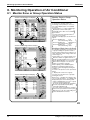
Monitor Zone or Group Operation Status ...............................................38
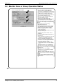
Monitor Zone or Group Operation Status ...............................................39
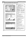
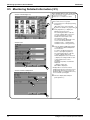
Monitoring Detailed Information (1/3) .....................................................40
Monitoring Detailed Information (2/3) .....................................................41
Monitoring Detailed Information (3/3) .....................................................42
To set/release the lock of screen operation ...........................................43
Table of Contents
SiEN72-501
9. System Setup Menu..............................................................................44
9.1
9.2
9.3
9.4
9.5
9.6
9.7
9.8
9.9
9.10
9.11
9.12
9.13
9.14
9.15
9.16
9.17
9.18
9.19
9.20
9.21
9.22
9.23
9.24
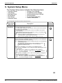
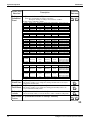
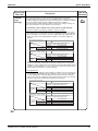
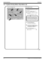
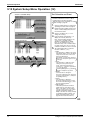
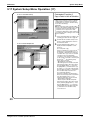
System Setup Menu Operation (1).........................................................61
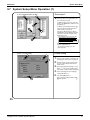
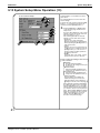
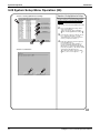
System Setup Menu Operation (2).........................................................62
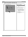
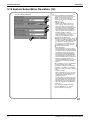
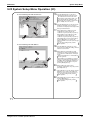
System Setup Menu Operation (3).........................................................63
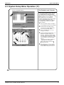
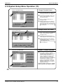
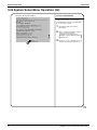
System Setup Menu Operation (4).........................................................64
System Setup Menu Operation (5).........................................................65
System Setup Menu Operation (6).........................................................66
System Setup Menu Operation (7).........................................................67
System Setup Menu Operation (8).........................................................68
System Setup Menu Operation (9).........................................................69
System Setup Menu Operation (10).......................................................70
System Setup Menu Operation (11).......................................................71
System Setup Menu Operation (12).......................................................72
System Setup Menu Operation (13).......................................................73
System Setup Menu Operation (14).......................................................74
System Setup Menu Operation (15).......................................................75
System Setup Menu Operation (16).......................................................76
System Setup Menu Operation (17).......................................................77
System Setup Menu Operation (18).......................................................78
System Setup Menu Operation (19).......................................................79
System Setup Menu Operation (20).......................................................80
System Setup Menu Operation (21).......................................................81
System Setup Menu Operation (22).......................................................82
System Setup Menu Operation (23).......................................................83
System Setup Menu Operation (24).......................................................84
10.Precautions ...........................................................................................85
11.Maintenance..........................................................................................86
12.Troubleshooting ....................................................................................87
13.Options..................................................................................................94
14.Specification..........................................................................................95
14.1 Specification ...........................................................................................95
14.2 Dimensions.............................................................................................95
15.After-sales Service ................................................................................96
15.1 After-sales Service .................................................................................96
Part 3 Power Proportional Distribution Software Operation
Manual .............................................................................. 97
1.
2.
3.
4.
5.
6.
7.
8.
9.
Table of Contents
Safety Consideration.............................................................................98
Functions and Outline ...........................................................................99
Preparation..........................................................................................100
Simplified Chart...................................................................................100
Initial Setup .........................................................................................100
Power Proportional Distribution Report Output Procedures................102
How to Output Power Proportional Distribution Report.......................102
Troubleshooting ..................................................................................106
After-Sales Service .............................................................................107
iii
SiEN72-501
Part 4 intelligent Touch Controller Web Software Operation
Manual ............................................................................ 109
1.
2.
3.
4.
5.
6.
Safety Consideration...........................................................................110
Before Starting ....................................................................................112
About Web Interface ...........................................................................112
Overview .............................................................................................113
Basic Mode .........................................................................................116
Advanced Mode ..................................................................................131
Part 5 intelligent Touch Controller Test Operation Manual .... 137
1. intelligent Touch Controller Test Operations Flow
(For New Installation) ..........................................................................138
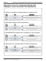
2. Operations Flow for Changing Settings after
intelligent Touch Controller Test Operations.......................................139
2.1
2.2
2.3
2.4
2.5
2.6
2.7
2.8
2.9
2.10
2.11
2.12
2.13
2.14
2.15
2.16
2.17
2.18
2.19
2.20
2.21
2.22
2.23
2.24
2.25
Download Software and License Key...................................................140
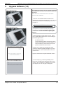
Upgrade Software (1/2) ........................................................................141
Upgrade Software (2/2) ........................................................................142
Check for Centralized Control Devices in Simultaneous Use (1/2) ......143
Check for Centralized Control Devices in Simultaneous Use (2/2) ......144
Set Connector for DIII-NET Parent Centralized Control.......................145
Select Display Language on ITC Screen .............................................146
Set Data Backup Battery Switch ..........................................................147
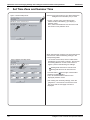
Set Time Zone and Summer Time .......................................................148
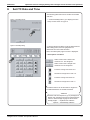
Set ITC Date and Time.........................................................................149
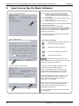
Input License Key (for Basic Software) ................................................150
Input License Key (for Option Software) ..............................................151
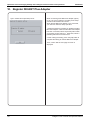
Register DIII-NET Plus Adapter ...........................................................152
Set ITC as Master or Slave ..................................................................153
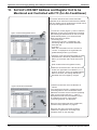
Set Unit’s DIII-NET Address and Register Unit to be Monitored and
Controlled with ITC (for Air-Conditioner) ..............................................154
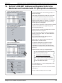
Set Unit’s DIII-NET Address and Register Units to be Monitored and
Controlled with ITC (Except Air-conditioner) ........................................155
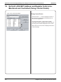
Set Unit’s DIII-NET Address and Register Units to be Monitored and
Controlled (Fixing Control Points) ........................................................156
Monitor Registered Units......................................................................157
Service Login on System Menu............................................................158
Service Login during Administrator Password Protection Setting ........159
Set Cooling/Heating Control in In-house Air-conditioner with ITC........160
Add Option Software after Test Operations .........................................161
Add DIII-NET Plus Adapter after Test Operations................................162
Connect Additional Units to ITC (for Air-conditioner) ...........................163
Connect Additional Units to ITC (for Other Equipment) .......................164
Part 6 Power Proportional Distribution Software
Test Run ......................................................................... 165
Introduction ..............................................................................................166
1. Test Run Procedure ............................................................................167
2. PPD Setting (Service Mode) ...............................................................168
iv
Table of Contents
SiEN72-501
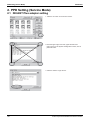
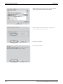
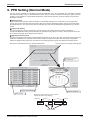
2.1 DIII-NET Plus adapter setting...............................................................168
2.2 DIII Port Setting (Service Mode)...........................................................171
2.3 Pulse Input Port Setting (Service Mode) ..............................................173
3. Service PC Setting ..............................................................................175
3.1 Required performance of Service PC...................................................175
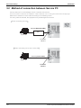
3.2 Method of connection between Service PC .........................................176
4. Startup and Connection of Service PC ...............................................177
4.1 Connection between Service PC and intelligent Touch Controller.......177
5. Formatting ...........................................................................................180
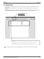
6. Setup Port ...........................................................................................181
7. Hardware Setting ................................................................................182
7.1 Automatic Setting .................................................................................183
7.2 Manual Setting .....................................................................................184
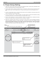
8. Power Group Setting...........................................................................185
8.1 Power Group Editing ............................................................................186
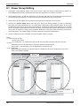
9. PPD Setting (Normal Mode)................................................................187
9.1 Off-time Period (Normal) Setting ..........................................................188
9.2 Special Day (Normal) Setting for Proportional Distribution ..................189
10.Confirmation of operation....................................................................190
10.1 Confirmation of the Type of Integrating Watt-hour Meter .....................191
10.2 Confirmation of Power Pulse Input.......................................................192
10.3 Confirmation of Integrated Power Consumption Values ......................193
11.Operation Confirmation ......................................................................194
11.1 Confirmation of Integrated Power.........................................................195
11.2 Confirmation of Current Integrated Values...........................................197
11.3 Confirmation of Tentative Consumed Power........................................199
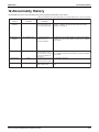
12.Abnormality History .............................................................................201
13.In Such a Case....................................................................................202
13.1 Memory Card........................................................................................202
13.2 Watt-hour Meter ...................................................................................203
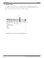
13.3 Model Data ...........................................................................................204
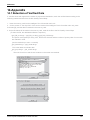
14.Appendix .............................................................................................205
14.1 Retention of Verified Data ....................................................................205
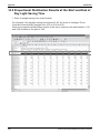
14.2 Proportional Distribution Results at the Start and End of Day Light
Saving Time .........................................................................................206
Part 7 Troubleshooting ............................................................. 209
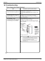
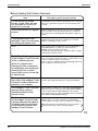
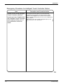
Before Having the Product Serviced ........................................................210
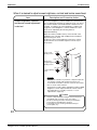
Emergency Procedure for intelligent Touch Controller Failure.................212
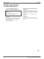
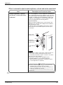
When it is desired to adjust screen brightness, contrast and
buzzer sound level ..............................................................................213
Table of Contents
v
Introduction
SiEN72-501
1. Introduction
1.1
Safety Cautions
Cautions and
Warnings
Be sure to read the following safety cautions before conducting repair work.
The caution items are classified into “
Warning” and “
Caution”. The “
Warning”
items are especially important since they can lead to death or serious injury if they are not
followed closely. The “
Caution” items can also lead to serious accidents under some
conditions if they are not followed. Therefore, be sure to observe all the safety caution items
described below.
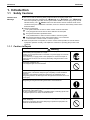
About the pictograms
This symbol indicates an item for which caution must be exercised.
The pictogram shows the item to which attention must be paid.
This symbol indicates a prohibited action.
The prohibited item or action is shown inside or near the symbol.
This symbol indicates an action that must be taken, or an instruction.
The instruction is shown inside or near the symbol.
After the repair work is complete, be sure to conduct a test operation to ensure that the
equipment operates normally, and explain the cautions for operating the product to the
customer
1.1.1 Caution in Repair
Warning
Be sure to disconnect the power cable plug from the plug socket before
disassembling the equipment for a repair.
Working on the equipment that is connected to a power supply can cause an
electrical shook.
If it is necessary to supply power to the equipment to conduct the repair or
inspecting the circuits, do not touch any electrically charged sections of the
equipment.
If the refrigerant gas discharges during the repair work, do not touch the
discharging refrigerant gas.
The refrigerant gas can cause frostbite.
When disconnecting the suction or discharge pipe of the compressor at the
welded section, release the refrigerant gas completely at a well-ventilated
place first.
If there is a gas remaining inside the compressor, the refrigerant gas or
refrigerating machine oil discharges when the pipe is disconnected, and it can
cause injury.
If the refrigerant gas leaks during the repair work, ventilate the area. The
refrigerant gas can generate toxic gases when it contacts flames.
The step-up capacitor supplies high-voltage electricity to the electrical
components of the outdoor unit.
Be sure to discharge the capacitor completely before conducting repair work.
A charged capacitor can cause an electrical shock.
Do not start or stop the air conditioner operation by plugging or unplugging the
power cable plug.
Plugging or unplugging the power cable plug to operate the equipment can
cause an electrical shock or fire.
vi
SiEN72-501
Introduction
Caution
Do not repair the electrical components with wet hands.
Working on the equipment with wet hands can cause an electrical shock.
Do not clean the air conditioner by splashing water.
Washing the unit with water can cause an electrical shock.
Be sure to provide the grounding when repairing the equipment in a humid or
wet place, to avoid electrical shocks.
Be sure to turn off the power switch and unplug the power cable when cleaning
the equipment.
The internal fan rotates at a high speed, and cause injury.
Do not tilt the unit when removing it.
The water inside the unit can spill and wet the furniture and floor.
Be sure to check that the refrigerating cycle section has cooled down
sufficiently before conducting repair work.
Working on the unit when the refrigerating cycle section is hot can cause burns.
Use the welder in a well-ventilated place.
Using the welder in an enclosed room can cause oxygen deficiency.
1.1.2 Cautions Regarding Products after Repair
Warning
Be sure to use parts listed in the service parts list of the applicable model and
appropriate tools to conduct repair work. Never attempt to modify the
equipment.
The use of inappropriate parts or tools can cause an electrical shock,
excessive heat generation or fire.
When relocating the equipment, make sure that the new installation site has
sufficient strength to withstand the weight of the equipment.
If the installation site does not have sufficient strength and if the installation
work is not conducted securely, the equipment can fall and cause injury.
Be sure to install the product correctly by using the provided standard
installation frame.
Incorrect use of the installation frame and improper installation can cause the
equipment to fall, resulting in injury.
Be sure to install the product securely in the installation frame mounted on a
window frame.
If the unit is not securely mounted, it can fall and cause injury.
Be sure to use an exclusive power circuit for the equipment, and follow the
technical standards related to the electrical equipment, the internal wiring
regulations and the instruction manual for installation when conducting
electrical work.
Insufficient power circuit capacity and improper electrical work can cause an
electrical shock or fire.
For integral units
only
For integral units
only
vii
Introduction
SiEN72-501
Warning
Be sure to use the specified cable to connect between the indoor and outdoor
units. Make the connections securely and route the cable properly so that there
is no force pulling the cable at the connection terminals.
Improper connections can cause excessive heat generation or fire.
When connecting the cable between the indoor and outdoor units, make sure
that the terminal cover does not lift off or dismount because of the cable.
If the cover is not mounted properly, the terminal connection section can cause
an electrical shock, excessive heat generation or fire.
Do not damage or modify the power cable.
Damaged or modified power cable can cause an electrical shock or fire.
Placing heavy items on the power cable, and heating or pulling the power cable
can damage the cable.
Do not mix air or gas other than the specified refrigerant (R410A) in the
refrigerant system.
If air enters the refrigerating system, an excessively high pressure results,
causing equipment damage and injury.
If the refrigerant gas leaks, be sure to locate the leak and repair it before
charging the refrigerant. After charging refrigerant, make sure that there is no
refrigerant leak.
If the leak cannot be located and the repair work must be stopped, be sure to
perform pump-down and close the service valve, to prevent the refrigerant gas
from leaking into the room. The refrigerant gas itself is harmless, but it can
generate toxic gases when it contacts flames, such as fan and other heaters,
stoves and ranges.
When replacing the coin battery in the remote controller, be sure to disposed
of the old battery to prevent children from swallowing it.
If a child swallows the coin battery, see a doctor immediately.
Caution
Installation of a leakage breaker is necessary in some cases depending on the
conditions of the installation site, to prevent electrical shocks.
Do not install the equipment in a place where there is a possibility of
combustible gas leaks.
If a combustible gas leaks and remains around the unit, it can cause a fire.
Be sure to install the packing and seal on the installation frame properly.
For integral units
If the packing and seal are not installed properly, water can enter the room and only
wet the furniture and floor.
1.1.3 Inspection after Repair
Warning
Check to make sure that the power cable plug is not dirty or loose, then insert
the plug into a power outlet all the way.
If the plug has dust or loose connection, it can cause an electrical shock or fire.
If the power cable and lead wires have scratches or deteriorated, be sure to
replace them.
Damaged cable and wires can cause an electrical shock, excessive heat
generation or fire.
Do not use a joined power cable or extension cable, or share the same power
outlet with other electrical appliances, since it can cause an electrical shock,
excessive heat generation or fire.
viii
SiEN72-501
Introduction
Caution
Check to see if the parts and wires are mounted and connected properly, and
if the connections at the soldered or crimped terminals are secure.
Improper installation and connections can cause excessive heat generation,
fire or an electrical shock.
If the installation platform or frame has corroded, replace it.
Corroded installation platform or frame can cause the unit to fall, resulting in
injury.
Check the grounding, and repair it if the equipment is not properly grounded.
Improper grounding can cause an electrical shock.
Be sure to measure the insulation resistance after the repair, and make sure
that the resistance is 1 Mohm or higher.
Faulty insulation can cause an electrical shock.
Be sure to check the drainage of the indoor unit after the repair.
Faulty drainage can cause the water to enter the room and wet the furniture
and floor.
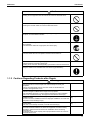
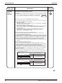
1.1.4 Using Icons
Icons are used to attract the attention of the reader to specific information. The meaning of each
icon is described in the table below:
1.1.5 Using Icons List
Icon
Type of
Information
Note
Description
A “note” provides information that is not indispensable, but may
nevertheless be valuable to the reader, such as tips and tricks.
Note:
Caution
A “caution” is used when there is danger that the reader, through
incorrect manipulation, may damage equipment, loose data, get
an unexpected result or has to restart (part of) a procedure.
Warning
A “warning” is used when there is danger of personal injury.
Reference
A “reference” guides the reader to other places in this binder or
in this manual, where he/she will find additional information on a
specific topic.
Caution
Warning
ix
Introduction
x
SiEN72-501
SiEN72-501
Part 1
intelligent Touch
Controller Hardware
Manual
1. System Overview ....................................................................................2
2. Part Names and Functions......................................................................3
2.1 Front and Side View .................................................................................3
2.2 Terminals on the Back of intelligent Touch Controller..............................4
3. Precautions .............................................................................................5
3.1 Internal Battery Enable (ON)/Disable (OFF) Switch.................................5
4. Maintenance............................................................................................6
5. Options....................................................................................................7
6. Specification............................................................................................8
6.1 Specification .............................................................................................8
6.2 Dimension ................................................................................................8
7. After-sales Service ..................................................................................9
7.1 After-sales Service ...................................................................................9
EM04A054A
intelligent Touch Controller Hardware Manual
1
System Overview
SiEN72-501
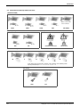
1. System Overview
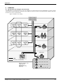
This intelligent Touch Controller is capable of controlling/monitoring up to 64 groups of indoor units (hereafter
“groups”).
The main functions of the intelligent Touch Controller include:
1. Collective starting/stopping of operation of the indoor units connected to the intelligent Touch Controller.
2. Starting/stopping of operation, temperature setting, switching between temperature control modes and
enabling/disabling of operation with the hand-held remote control by zone or group .
3. Scheduling by zone or group .
4. Monitoring of the operation status by zone or group .
5. Display of the air conditioner operation history.
6. Compulsory contact stop input from the central monitoring panel (non-voltage, normally-open contact).
7. Power distribution of the air conditioners. (With the optional DCS002C51)
8. Control and Monitoring of air conditioner with personal computer by the Controller (with the optional
DCS004A51).
∗ A group of indoor units include:
1 One indoor unit without a remote control.
2 One indoor unit controlled with one or two remote controls.
Indoor unit
or
No remote control
Remote control
Remote control
3 Up to 16 indoor units controlled with one or two remote controls.
Remote control
Up to 16 units
Two remote controls
Up to 16 units
∗ Zone control with the intelligent Touch Controller
∗ Zone control, which allows collective settings for more than one group, is available with the intelligent Touch
Controller, which facilitates the setting operations.
Zone 1
Zone 2
Zone 3
Zone 4
intelligent Touch Controller
Zone 5
One setting makes the same setting for all of the units in one zone.
Up to 128 zones can be set with one intelligent Touch Controller.
(The maximum number of groups in one zone is 64.)
Groups can be zoned at will with the intelligent Touch Controller.
Units in one group can be divided into more than one zone.
2
intelligent Touch Controller Hardware Manual
SiEN72-501
Part Names and Functions
2. Part Names and Functions
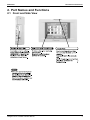
2.1 Front and Side View
intelligent Touch Controller Hardware Manual
3
Part Names and Functions
SiEN72-501
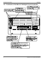
2.2 Terminals on the Back of intelligent Touch Controller
III
III
III
4
intelligent Touch Controller Hardware Manual
SiEN72-501
Precautions
3. Precautions
3.1 Internal Battery Enable (ON)/Disable (OFF) Switch
The intelligent Touch Controller is equipped with internal batteries in order to run the clock during
blackouts as well as to save data during blackouts when using the optional Power Proportional
Distribution. The batteries can be enabled and disabled using the switches shown in the figure below.
The clock and Power Proportional Distribution will not function properly when a blackout occurs
if this switch is turned to ⎡ OFF ⎦ .
The switches are turned to ⎡ON ⎦ when the unit is installed. Do not touch them unless the power
has been turned off for a long time. (See the next page for details on what to do if the power has
been off for long periods of time.)
<Location and Setting of Switches>
As shown in the figure, set the battery switch on the left side of this controller to “OFF” (switch knob
upper side) or “ON” (switch knob lower side), using a precision minus(-) screwdriver.
(Turning this switch OFF does not erase the settings for groups, zones or schedule.)
OFF
ON
is the location of the knob.
RE
SE
T
NOTE
z Do not touch other switches.
z Avoid turning the switch ON and
OFF with excessive force; otherwise
such operation may lead to parts
damage and failure.
intelligent Touch Controller Hardware Manual
5
Maintenance
SiEN72-501
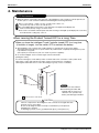
4. Maintenance
LCD Maintenance
Note
z When the surface of the LCD or the main unit of the intelligent Touch Controller is soiled, wipe the soil
off with a piece of cloth soaked in a diluted neutral detergent and wrung sufficiently.
z Do not use thinner, organic solvent, strongly acid solution, etc.
The print may fade or wear out and discolor.
z Forced rubbing with hard cloth may cause damage to the liquid crystal display unit.
Remove stains, always using a soft waste cloth.
z If the unit is stored with water droplets and stains sticking to the liquid crystal display unit, a blot may
be made and the coating may come off.
When Leaving the Product Turned OFF for a Long Time
When you leave the intelligent Touch Controller turned OFF for a long time
(6 months or longer), turn the switch OFF to maintain the battery.
z The intelligent Touch Controller has a built-in battery for operating the clock in power failure.
The battery mentioned above is for power failure only and it may be completely discharged if no power
is provided for a long time.
(The capacity is worth about 2 years of in total if no power is supplied.)
z To use the intelligent Touch Controller again, turn the switch ON.
[Setting the switch]
As shown in the figure, set the battery switch on the left side of this controller to “OFF” (switch knob
upper side) or “ON” (switch knob lower side), using a precision minus(-) screwdriver.
(Turning this switch OFF does not erase the settings for groups, zones or schedule.)
OFF
ON
NOTE
RE
SE
T
z Do not touch other switches.
z Avoid turning the switch ON
and OFF with excessive force;
otherwise such operation may
lead to parts damage and failure.
is the location of the knob.
CAUTION
If electric components in the intelligent Touch Controller are charged with static
electricity, it may cause failure.
Be sure to discharge the static electricity accumulated in your body before
attempting any operation.
To discharge yourself, touch a grounded metal object (control panel, etc.).
6
intelligent Touch Controller Hardware Manual
SiEN72-501
Options
5. Options
III
III
III
intelligent Touch Controller Hardware Manual
7
Specification
SiEN72-501
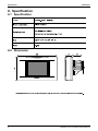
6. Specification
6.1 Specification
×
×
×
×
6.2 Dimension
8
intelligent Touch Controller Hardware Manual
SiEN72-501
After-sales Service
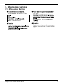
7. After-sales Service
7.1 After-sales Service
intelligent Touch Controller Hardware Manual
9
After-sales Service
10
SiEN72-501
intelligent Touch Controller Hardware Manual
SiEN72-501
Part 2
intelligent Touch
Controller Operation
Manual
1.
2.
3.
4.
Safety Considerations ...........................................................................13
System Overview ..................................................................................15
Features and Functions ........................................................................16
Part Names and Functions....................................................................17
4.1 Front and Side View ...............................................................................17
4.2 Terminals on the Back of intelligent Touch Controller............................18
5. Part Names on the Monitoring Screen and the Functions ....................19
6. Quick Reference ...................................................................................25
6.1 Air Conditioner Operation.......................................................................25
6.2 System Setup Menu ...............................................................................26
7. Air Conditioner Operation......................................................................27
7.1
7.2
7.3
7.4
7.5
7.6
7.7
7.8
7.9
7.10
7.11
Starting/Stopping Operation Collectively................................................27
Starting/Stopping Operation by the Group .............................................28
Starting/Stopping Operation by the Zone ...............................................29
Switching the Operation Mode ...............................................................30
Changing the Temperature Setting ........................................................31
Resetting the Filter/Element Sign...........................................................32
Changing the Direction/Fan Speed ........................................................33
Changing the Range of Operation Allowed with Remote Control ..........34
Set Ventilation Mode ..............................................................................35
Set Ventilation Volume ...........................................................................36
Permit/Inhibit setting of Ventilation Remote Control Operations ............37
8. Monitoring Operation of Air Conditioner................................................38
8.1
8.2
8.3
8.4
8.5
8.6
Monitor Zone or Group Operation Status ...............................................38
Monitor Zone or Group Operation Status ...............................................39
Monitoring Detailed Information (1/3) .....................................................40
Monitoring Detailed Information (2/3) .....................................................41
Monitoring Detailed Information (3/3) .....................................................42
To set/release the lock of screen operation ...........................................43
9. System Setup Menu..............................................................................44
9.1
9.2
9.3
9.4
9.5
9.6
9.7
9.8
System Setup Menu Operation (1).........................................................61
System Setup Menu Operation (2).........................................................62
System Setup Menu Operation (3).........................................................63
System Setup Menu Operation (4).........................................................64
System Setup Menu Operation (5).........................................................65
System Setup Menu Operation (6).........................................................66
System Setup Menu Operation (7).........................................................67
System Setup Menu Operation (8).........................................................68
intelligent Touch Controller Operation Manual
11
Si72-501
9.9
9.10
9.11
9.12
9.13
9.14
9.15
9.16
9.17
9.18
9.19
9.20
9.21
9.22
9.23
9.24
System Setup Menu Operation (9).........................................................69
System Setup Menu Operation (10).......................................................70
System Setup Menu Operation (11).......................................................71
System Setup Menu Operation (12).......................................................72
System Setup Menu Operation (13).......................................................73
System Setup Menu Operation (14).......................................................74
System Setup Menu Operation (15).......................................................75
System Setup Menu Operation (16).......................................................76
System Setup Menu Operation (17).......................................................77
System Setup Menu Operation (18).......................................................78
System Setup Menu Operation (19).......................................................79
System Setup Menu Operation (20).......................................................80
System Setup Menu Operation (21).......................................................81
System Setup Menu Operation (22).......................................................82
System Setup Menu Operation (23).......................................................83
System Setup Menu Operation (24).......................................................84
10.Precautions ...........................................................................................85
11.Maintenance..........................................................................................86
12.Troubleshooting ....................................................................................87
13.Options..................................................................................................94
14.Specification..........................................................................................95
14.1 Specification ...........................................................................................95
14.2 Dimensions.............................................................................................95
15.After-sales Service ................................................................................96
15.1 After-sales Service .................................................................................96
EM04A055
12
intelligent Touch Controller Operation Manual
SiEN72-501
Safety Considerations
1. Safety Considerations
Please read these “SAFETY CONSIDERATIONS” carefully before installing air conditioning equipment
and be sure to install it correctly.
After completing the installation, make sure that the unit operates properly during the start-up operation.
Please instruct the customer on how to operate the unit and keep it maintained.
Also, inform customers that they should store this installation manual along with the operation manual for
future reference. This air conditioner comes under the term “appliances not accessible to the general
public”.
Meaning of warning, caution and note symbols.
WARNING............. Indicates a potentially hazardous situation which, if not avoided, could result in
death or serious injury.
CAUTION .............. Indicates a potentially hazardous situation which, if not avoided, may result in
minor or moderate injury. It may also be used to alert against unsafe practices.
NOTE .................... Indicates situation that may result in equipment or property-damage-only
accidents.
Keep these warning sheets handy so that you can refer to them if needed.
Also, if this equipment is transferred to a new user, make sure to hand over this operation manual to the
new user.
WARNING
CAUTION
In order to avoid electric shock, fire or injury, or if you detect any abnormality such as smell of fire,
turn off power and call your dealer for instructions.
Ask your dealer for installation of the air conditioner.
Incomplete installation performed by yourself may result in a water leakage, electric shock, and fire.
Ask your dealer for improvement, repair, and maintenance.
Incomplete improvement, repair, and maintenance may result in a water leakage, electric shock, and fire.
Improper installation or attachment of equipment or accessories could result in electric shock,
short-circuit, leaks, fire or other damage to the equipment. Be sure only to use accessories made
by Daikin which are specifically designed for use with the equipment and have them installed by a
professional.
Ask your dealer to move and reinstall the air conditioner or the remote control.
Incomplete installation may result in a water leakage, electric shock, and fire.
Never let the indoor unit or the remote control get wet.
It may cause an electric shock or a fire.
Never use flammable spray such as hair spray, lacquer or paint near the unit.
It may cause a fire.
Never replace a fuse with that of wrong ampere ratings or other wires when a fuse blows out.
Use of wire or copper wire may cause the unit to break down or cause a fire.
Never inspect or service the unit by yourself.
Ask a qualified service person to perform this work.
Cut off all electric waves before maintenance.
Do not wash the air conditioner or the remote control with excessive water.
Electric shock or fire may result.
Do not install the air conditioner or the remote control at any place where flammable gas may leak
out.
If the gas leaks out and stays around the air conditioner, a fire may break out.
Do not touch the switch with wet fingers.
Touching a switch with wet fingers can cause electric shock.
CISPR 22 Class A Warning:
This is a class A product. In a domestic environment this product may cause radio interference in which
case the user may be required to take adequate measures.
After a long use, check the unit stand and fitting for damage.
If they are left in a damaged condition, the unit may fall and result in injury.
Do not allow a child to mount on the unit or avoid placing any object on it.
Falling or tumbling may result in injury.
Do not let children play on and around the unit.
If they touch the unit carelessly, it may result in injury.
Do not place a flower vase and anything containing water.
Water may enter the unit, causing an electric shock or fire.
intelligent Touch Controller Operation Manual
13
Safety Considerations
SiEN72-501
Never touch the internal parts of the controller.
Do not remove the front panel. Some parts inside are dangerous to touch, and a machine trouble may
happen.
For checking and adjusting the internal parts, contact your dealer.
Avoid placing the controller in a spot splashed with water.
Water coming inside the machine may cause an electric leak or may damage the internal electronic parts.
Do not operate the air conditioner when using a room fumigation - type insecticide.
Failure to observe could cause the chemicals to become deposited in the unit, which could endanger the
health of those who are hypersensitive to chemicals.
Safely dispose of the packing materials.
Packing materials, such as nails and other metal or wooden parts, may cause stabs or other injuries.
Tear apart and throw away plastic packaging bags so that children will not play with them. If children play
with a plastic bag which was not torn apart, they face the risk of suffocation.
Do not turn off the power immediately after stopping operation.
Always wait at least five minutes before turning off the power. Otherwise, water leakage and trouble may
occur.
The appliance is not intended for use by young children or infirm persons without supervision.
The remote control should be installed in such away that children cannot play with it.
Use the card provided in the same package.
NOTE
14
Never press the button of the remote control with a hard, pointed object.
The remote control may be damaged.
Never pull or twist the electric wire of the remote control.
It may cause the unit to malfunction.
Do not place the controller exposed to direct sunlight.
The LCD display may get discolored, failing to display the data.
Do not wipe the controller operation panel with benzine, thinner, chemical dustcloth, etc.
The panel may get discolored or the coating peeled off. If it is heavily dirty, soak a cloth in water-diluted
neutral detergent, squeeze it well and wipe the panel clean. And wipe it with another dry cloth.
Dismantling of the unit, treatment of the refrigerant, oil and eventual other parts, should be done in
accordance with the relevant local and national regulations.
intelligent Touch Controller Operation Manual
SiEN72-501
System Overview
2. System Overview
This intelligent Touch Controller is capable of controlling/monitoring up to 64 groups of indoor units (hereafter
“groups”).
The main functions of the intelligent Touch Controller include:
1. Collective starting/stopping of operation of the indoor units connected to the intelligent Touch Controller.
2. Starting/stopping of operation, temperature setting, switching between temperature control modes and
enabling/disabling of operation with the hand-held remote control by zone or group .
3. Scheduling by zone or group .
4. Monitoring of the operation status by zone or group .
5. Display of the air conditioner operation history.
6. Compulsory contact stop input from the central monitoring panel (non-voltage, normally-open contact).
7. Power distribution of the air conditioners. (With the optional DCS002A51)
∗ A group of indoor units include:
One indoor unit without a remote control.
One indoor unit controlled with one or two remote controls.
Indoor unit
or
No remote control
Remote control
Remote control
Up to 16 indoor units controlled with one or two remote controls.
Remote control
Up to 16 units
Two remote controls
Up to 16 units
∗ Zone control with the intelligent Touch Controller
∗ Zone control, which allows collective settings for more than one group, is available with the intelligent Touch
Controller, which facilitates the setting operations.
Zone 1
Zone 2
Zone 3
Zone 4
intelligent Touch Controller
Zone 5
• One setting makes the same setting for all of the units in one zone.
• Up to 128 zones can be set with one intelligent Touch Controller.
(The maximum number of groups in one zone is 64.)
• Groups can be zoned at will with the intelligent Touch Controller.
• Units in one group can be divided into more than one zone.
3
intelligent Touch Controller Operation Manual
15
Features and Functions
SiEN72-501
3. Features and Functions
nOperation Menu
See pages
intelligent Touch Controller is capable of starting/stopping of the operation by the
group or zone. Collective starting/stopping is also available.
nAir Conditioner Detail Setup
Temperature setting, switching between temperature control modes, switching of
speed and direction of wind and remote control mode setting are available by the
group, by the zone or collectively.
nMonitoring of Various Information on Indoor Units
Information on operation such as the operation mode and temperature setting of
the indoor units, maintenance information including the filter or element cleaning
sign, troubleshooting information such as error codes can be displayed by the
group or the zone.
15
to
17
See pages
18
to
22
See pages
26
to
29
nDiversified Operation Modes
Operation can be controlled both with the main unit and the remote control to
provide diversified operation management. Setting with the main unit allows the
following remote control settings by the group, by the zone or collectively:
1. Start/Stop
2. Operation Mode
3.Temperature Setting
:(Remote control) Inhibited
:(Remote control) Permitted
:Priority
22
See page
:(Remote control) Inhibited :(Remote control) Inhibited
:(Remote control) Permitted :(Remote control) Permitted
nZone Control Simplifying Complicated Setting Operations
Up to 64 groups can be controlled with the intelligent Touch Controller.
More than one group can be consolidated into a zone, which can be registered,
to allow the following settings by the zone. This eliminates the need for repeating
the same setting operation for each group. Function to allow collective setting for
all groups is also available.
• Start/stop
• Temperature setting
• Switching between operation modes
• Setting of direction and fan speed
• Disabling/enabling the remote control
nDetailed Scheduled Operation Control
The intelligent Touch Controller allows detailed scheduled operation by the group,
by the zone or collectively. Up to 8 options for annual schedule can be set. Each
schedule can include four types of plans: for Weekdays, Holidays, Special days 1
and Special days 2. Each of the plans allows setting of up to 16 operations.
See pages
15
to
29
33
See pages
35
to
36
nHandy Automated Control
The Intelligent Touch Controller can do the following.
• Change Over Settings: automatically switches between cooling and heating
according to the room temperature.
• Temperature Limit Settings: prevents the temperature from rising too high or
too low in unmanned rooms.
• Heating Optimization Settings: stops uncomfortable hot air from blowing when
the heating thermo is off.
See pages
37
to
46
4
16
intelligent Touch Controller Operation Manual
SiEN72-501
Part Names and Functions
4. Part Names and Functions
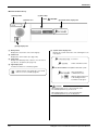
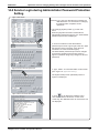
4.1 Front and Side View
PCMCIA Card Slot
Used when using the optional
Power Proportional Distribution
(DCS002C51) or updating the
intelligent Touch Controller
software to a newer version.
Color LCD with Touch Panel
Touch Pen
Provides a display for monitoring
and operation.
Be sure to use the touch pen
provided for operation.
Use the touch pen for operation.
Be sure to use the touch pen for
operation.
Use caution not to lose the touch
pen.
When the pen is lost, contact the
dealer you purchased the
product from.
Note
Be sure to use the touch pen for
operation of the touch panel of
the intelligent Touch Controller.
Operating with an object other
than the touch pen provided may
cause damage and failure.
5
intelligent Touch Controller Operation Manual
17
Part Names and Functions
SiEN72-501
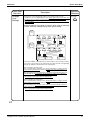
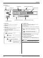
4.2 Terminals on the Back of intelligent Touch Controller
Terminal block for power supply
Modem connector for AIRNET
When using AIRNET service,
connect it to the telephone line.
Connect to AC100-240V power supply.
Terminal size is M4.
RS232-C connector for
DIII-NET Plus adapter
Using DIII-NET Plus adapter
being sold as an accessory,
you can increase the number
of indoor units to be controlled.
Earth terminal block
Securely connect the earth wire.
Terminal size is M4.
LINE
PHONE
RS-232C
LAN
COM Dil
Pi3 COM Pi2 Pi1
F2
F1
L0
L2
L1
Ethernet connector for web
When monitoring and operating
the indoor units using the optional
Web and E-mail function software
sold separately, connect to LAN
via Ethernet cable.
Terminal block for DIII-NET
communication
The terminal size of the terminal
block for communication with
indoor units is M3.5.
Terminal block for watt hour meter and force stop
input of indoor units
This is used when distributing the power supply to indoor
units using optional Power Proportional Distribution software
sold separately and when stopping the indoor units
compulsorily by contact input.
The size of terminal block is M3.5.
6
18
intelligent Touch Controller Operation Manual
SiEN72-501
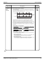
Part Names on the Monitoring Screen and the Functions
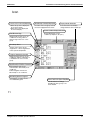
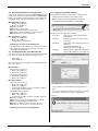
5. Part Names on the Monitoring Screen and the
Functions
List
Contents of the List Currently Displayed
Zone/Group Currently Displayed
Display Mode Selection
• When Group List is displayed
“Zone: Zone Name”
• When Zone List is displayed
“Zone List”
The name of the zone/group
currently selected is highlighted
in light-blue.
Press the button and display
change between Zone and Group.
System Condition Displayed Domain
Zone/Group Name
Domain displaying system
condition (Compulsory Stop etc.)
Set the names in the Group
Registration or Zone Registration
in the System Setup Mode.
Target of Automatic Control
Displayed when there is any air
conditioner with the registration of
scheduled in the zone or in the
group.
Filter/Element Sign
Displayed when there is any air
conditioner showing a filter or
element sign in the zone or the
group.
Monitoring Screen Legend
Pressing the “?” button shows
more detailed legend.
Button to Switch to the System Setup Mode
Use this button for settings
including the time, group, zone
and schedule.
7
intelligent Touch Controller Operation Manual
19
Part Names on the Monitoring Screen and the Functions
SiEN72-501
List
Display for Collective Monitoring of Air
Conditioners Connected to intelligent Touch Controller
When operation is normal and any air
conditioner is in operation:
Red/Normal
When operation is normal and all air
conditioners are in stoppage:
Green/Normal
When there is any air conditioner
generating an error:
Yellow/Abnormal
When there is any air conditioner with
communication error:
Blue/Abnormal
Change in color of Start/Stop is
possible by Iconcolor Settings in
System Settings.
Start All Button
Button to collectively start all the
air conditioners connected to
intelligent Touch Controller.
Stop All Button
Button to collectively stop all the
air conditioners connected to
intelligent Touch Controller.
Display Mode Selection
Select the mode among
icon/list/detailed icon.
Displayed in List in the right figure.
Icon display is P9, 10.
Detailed icon display is P11, 12.
Group/Zone Start Button
Button to start operation of the
group/zone selected.
Group/Zone Stop Button
Button to stop operation of the
group/zone selected.
Group/Zone Set Button
Makes settings (temperature
setting, temperature control mode,
etc.) and display of the
group/zone selected.
Scroll Buttons
Group/Zone Prop Button
Up/Down scroll button used when
monitoring zone/group which are
not currently displayed.
Left/Right scroll button used
when monitoring temperature
and errors etc.
Which are not currently
displayed.
Detailed display of the
group/zone selected
Lock Setting/Cancel Button
Current Time Display
Displays possibititiy of monitor
operation.
Expresses detailed information in
P31, 32.
Shows the current date and time.
8
20
intelligent Touch Controller Operation Manual
SiEN72-501
Part Names on the Monitoring Screen and the Functions
Icon
Contents of the List Currently Displayed
• When Group List is displayed
“Zone: Zone Name”
• When Zone List is displayed
“Zone List Display”
Filter/Element Sign
Zone/Group Currently Displayed
Display Mode Selection
The name of the zone/group currently
selected is highlighted in blue flame.
Select between Zone and Group.
System Condition Displayed Domain
Domain displaying system
condition (Compulsory Stop etc.)
Displayed when there is any air
conditioner showing a filter or
element sign in the zone or the
group.
Zone/Group Name
Set the names in the Group
Registration or Zone Registration
in the System Setup Mode.
Target of Automatic Control
Displayed when there is any air
conditioner with the registration of
scheduled in the zone or in the
group.
Description of Zone/Group
Set the names in the Group
Registration or Zone Registration
in the System Setup Mode.
Monitoring Screen Legend
Displayed Abnormality in Air Conditioner or Communication
Pressing the “?” button shows
more detailed legend.
Blue triangular mark shows
communication abnormality in air
conditioner.
Yellow triangular mark shows
abnormality in air conditioner.
Information on Zone/Group Currently Displayed
Generally, the temperature setting
and the operation mode are
displayed. If any error occurs in the
air conditioner, the error code is
displayed.
Button to Switch to the System Setup Mode
Use this button for settings
including the time, group, zone
and schedule.
9
intelligent Touch Controller Operation Manual
21
Part Names on the Monitoring Screen and the Functions
SiEN72-501
Icon
Display for Collective Monitoring of Air
Conditioners Connected to intelligent Touch Controller
When operation is normal and any air
conditioner is in operation:
Red/Normal
When operation is normal and all air
conditioners are in stoppage:
Green/Normal
When there is any air conditioner
generating an error:
Yellow/Abnormal
When there is any air conditioner with
communication error:
Blue/Abnormal
Change in color of Start/Stop is
possible by Iconcolor Settings in
System Settings.
Start All Button
Button to collectively start all the
air conditioners connected to
intelligent Touch Controller.
Stop All Button
Button to collectively stop all the
air conditioners connected to
intelligent Touch Controller.
Display Mode Selection
Select the mode among
icon/list/detailed icon.
Displayed is List in the right figure.
List display in P7, 8.
Detailed icon display is P11, 12.
Group/Zone Start Button
Button to start operation of the
group/zone selected.
Group/Zone Stop Button
Button to stop operation of the
group/zone selected.
Group/Zone Set Button
Makes settings (temperature
setting, temperature control mode,
etc.) and display of the
group/zone selected.
Scroll Buttons
Group/Zone Prop Button
Up/Down scroll button used when
monitoring zone/group which are
not currently displayed.
Left/Right scroll button used
when monitoring temperature
and errors etc.
Which are not currently
displayed.
Detailed display of the
group/zone selected
Lock Setting/Cancel Button
Current Time Display
Displays possibititiy of monitor
operation.
Expresses detailed information in
P31, 32.
Shows the current date and time.
10
22
intelligent Touch Controller Operation Manual
SiEN72-501
Part Names on the Monitoring Screen and the Functions
Icon
Contents of the List Currently Displayed
Zone/Group Currently Displayed
Display Mode Selection
The name of the zone/group currently
selected is highlighted in blue frame.
Press the button ana display
change between Zone and Group.
• When Group List is displayed
“Zone: Zone Name”
• When Zone List is displayed
“Zone List Display”
Filter/Element Sign
System Condition Displayed Domain
Domain displaying system
condition (Compulsory Stop etc.).
Displayed when there is any air
conditioner showing a filter or
element sign in the zone or the
group.
Zone/Group Name
Set the names in the Group
Registration or Zone Registration
in the System Setup Mode.
Target of Automatic Control
Displayed when there is any air
conditioner with the registration of
scheduled in the zone or in the
group.
Displayed Abnormality in Air Conditioner or Communication
Blue triangular mark shows
communication abnormality in air
conditioner.
Yellow triangular mark shows
abnormality in air conditioner.
Monitoring Screen Legend
Pressing the “?” button shows
more detailed legend.
Button to Switch to the System Setup Mode
Use this button for settings
including the time, group, zone
and schedule.
11
intelligent Touch Controller Operation Manual
23
Part Names on the Monitoring Screen and the Functions
SiEN72-501
Icon
Display for Collective Monitoring of Air
Conditioners Connected to intelligent Touch Controller
When operation is normal and any air
conditioner is in operation:
Red/Normal
When operation is normal and all air
conditioners are in stoppage:
Green/Normal
When there is any air conditioner
generating an error:
Yellow/Abnormal
When there is any air conditioner with
communication error:
Blue/Abnormal
Change in color of Start/Stop is
possible by Iconcolor Settings in
System Settings.
Start All Button
Button to collectively start all the
air conditioners connected to
intelligent Touch Controller.
Stop All Button
Button to collectively stop all the
air conditioners connected to
intelligent Touch Controller.
Display Mode Selection
Select the mode among
icon/list/detailed icon.
Displayed in List in the right figure.
List display is P7, 8.
Icon display is P9, 10.
Group/Zone Start Button
Button to start operation of the
group/zone selected.
Group/Zone Stop Button
Button to stop operation of the
group/zone selected.
Group/Zone Set Button
Makes settings (temperature
setting, temperature control mode,
etc.) and display of the
group/zone selected.
Scroll Buttons
Group/Zone Prop Button
Up/Down scroll button used when
monitoring zone/group which are
not currently displayed.
Left/Right scroll button used
when monitoring temperature
and errors etc.
Which are not currently
displayed.
Detailed display of the
group/zone selected
Lock Setting/Cancel Button
Current Time Display
Displays possibititiy of monitor
operation.
Expresses detailed information in
P31, 32.
Shows the current date and time.
12
24
intelligent Touch Controller Operation Manual
SiEN72-501
Quick Reference
6. Quick Reference
6.1 Air Conditioner Operation
To collectively start/stop the operation of all devices connected
to the intelligent Touch Controller
See page
15
To start/stop the operation of devices by group
See page
16
To start/stop the operation of devices by zone
See page
17
To change the operation mode
See page
18
To change the temperature setting
See page
19
To reset the filter or element sign
See page
20
To change the direction or fan speed
See page
21
To change the range of operation allowed with remote control
See page
22
To change the ventilation mode
See page
23
To change the ventilation volume
See page
24
To permit/prohibit the remote control at hand for ventilation
See page
25
To monitor by zone or by group
See pages
26
to
27
To monitor detailed information
See pages
28
to
29
To monitor the operation condition for ventilation
See page
30
To set / release the lock of screen operation
See page
31
Air Conditioner Operation Monitoring
13
intelligent Touch Controller Operation Manual
25
Quick Reference
SiEN72-501
6.2 System Setup Menu
To change the name of a group
See page
33
To change the zone setup
See page
33
To change the schedule setup
See pages
35
to
36
To change the change over settings
See pages
37
to
41
To change the temperature limit settings
See pages
42
to
44
To change the heating optimization settings
See pages
45
to
46
To calibrate the touch panel
See page
48
To review the history of errors
See page
48
To set the locale
See page
34
To set the icon color
See page
34
To set the network
See page
34
To set the license key
See page
34
To adjust the contrast of the screen
See page
81
To set the e-mail
See page
47
14
26
intelligent Touch Controller Operation Manual
SiEN72-501
Air Conditioner Operation
7. Air Conditioner Operation
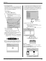
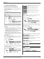
7.1 Starting/Stopping Operation Collectively
Screen 1 Monitoring
1
2
To start/stop the operation of
all devices connected
Start or stop collectively the operation of
devices connected.
On the Monitoring screen, operation is
allowed with either Zone or Group as the
display mode and with either Icon or List as
the display type. In the example on the left,
the display mode is Group in the collective
mode and the display type is Icon.
[Procedure]
Screen 1 Monitoring, press the [Start
1. On
All] button 1 or [Stop All] button 2.
Screen 2 Confirm
2. Screen 2 Confirm
appears. Press the
3
[OK] button .
To exit without activating collective
start or stop, press the [Cancel] button.
3
15
intelligent Touch Controller Operation Manual
27
Air Conditioner Operation
SiEN72-501
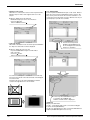
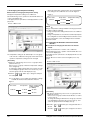
7.2 Starting/Stopping Operation by the Group
To start/stop the operation of
devices by group
Screen 1 Monitoring
Start or stop the operation of air conditioners
by group.
1
2
The example on the left shows the
screen for starting/stopping the
operation of Group Name: 1F North
registered for Zone Name: Canteen.
Zone Name
Canteen
1F North
1F West
Air conditioner
1F South group to be
started or
1F East stopped
2F North
Screen 2 Monitoring (Group)
2F West
3
2F South
4
2F East
5
3F North
[Procedure]
Screen 1 Monitoring, select a zone
1. On
from the button .
a zone that includes the group of
2. Select
which the operation is to be started or
stopped
.
a group from the button .
3. Select
Screen 2 Monitoring (Group) appears.
a group to be started or stopped
4. Select
as in and press the [Start] button
or [Stop] button
.
16
28
intelligent Touch Controller Operation Manual
SiEN72-501
Air Conditioner Operation
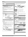
7.3 Starting/Stopping Operation by the Zone
To start/stop the operation of
devices by group
Screen 1 Monitoring
Start or stop by zone the operation of groups
of air conditioners set in zones.
1
2
3
4
The example on the left shows a screen for
starting or stopping the operation of air
conditioners in the canteen.
Zone Name
Collective Zone
Office
Canteen
Meeting
1F
2F
Air conditioner
group to be
started or
stopped
3F
[Procedure]
Screen 1 Monitoring, select a zone
1. On
from the button .
the zone of which the operation
2. Select
is to be started/stopped as shown in .
3. Press the [Start] button
button
or [Stop]
.
17
intelligent Touch Controller Operation Manual
29
Air Conditioner Operation
SiEN72-501
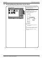
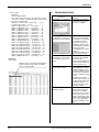
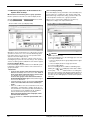
7.4 Switching the Operation Mode
Screen 1 Monitoring
1
Switch the operation mode of the air
conditioner.
On the Monitoring screen, operation is
allowed with either Icon or List as the display
type.
The operation mode can be switched by
zone or by group.
2
3
Selecting a zone and switching the
operation mode switches the mode of
all air conditioners in the zone.
Selecting a group and switching the
operation mode switches the mode of air
conditioners in the group selected.
[Procedure]
Screen 1 Monitoring, select a zone
1. On
or a group from the button .
with a zone or a group of
2. Select
which the operation mode is to be
Screen 2 Operation
switched.
3. Press the [Set] button
.
Screen 2 Operation appears.
4
the operation mode to be set
4. Select
from the pull down menu .
On the menu, operation modes
available for air conditioners in the
zone are displayed if the switching
is to be made by zone. See the
example below.
5. Press the [OK] button
.
To cancel the setting, press the
Cancel button.
5
Ex.: For the following zone setting, the
operation modes available are Fan,
Cool, Heat and Auto.
If Cool/Heat option is not available for
any air conditioner in the zone, Fan and
Set Point are the available operation
modes.
Zone name
Group name
Canteen
1F North
Operation modes available
“Cool”
“Air”
1F West
“Cool”
“Auto”
“Heat”
“Air”
18
30
intelligent Touch Controller Operation Manual
SiEN72-501
Air Conditioner Operation
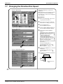
7.5 Changing the Temperature Setting
Screen 1 Monitoring
1
2
3
Change the temperature setting of air conditioners.
On the Monitoring screen, operation is allowed
with either Icon or List as the display type.
The temperature setting can be switched by zone
or by group.
Selecting a zone and changing the temperature
setting changes the setting of the air conditioner
groups in Cool, Heat, Auto or Temp operation in
the zone.
Selecting a group and changing the temperature
setting changes the temperature setting of air
conditioners in the group selected.
If all of the air conditioners in the group
selected are in Fan operation, temperature
setting cannot be changed.
[Procedure]
On Screen 1 Monitoring, select a zone or a
1. group
from the button .
Select a zone or a group of which the
2. temperature
setting is to be changed .
Press the [Set] button .
3. Screen
2 Operation appears.
For temperature setting, press the [Modify]
4. button
.
Screen 2 Operation
4
Set Temperature dialog is displayed and
input temperature for setting.
On the menu, temperature settings
available for air conditioners in the zone
are displayed if the setting is to be made
by the zone. See the example below.
5. Press the [OK] button
5
.
To cancel the setting, press the [Cancel]
button.
Ex.: For the following zone setting, the
temperature settings available are between
20 ºC and 30 ºC inclusive.
Zone name
Group name
Canteen
1F North
1F West
Range of temperature
settings available
(see Note)
25 to 30 ºC
20 to 25 ºC
When the temperature setting is 30 ºC, the
actual temperature settings for air
conditioners are as shown below:
Group name
1F North
1F West
Temperature setting
30 ºC
25 ºC
Note: Range of temperature settings available is
the range specified in accordance with the
following.
• Range of temperature setting inherent to
the air conditioner main unit.
• Range of temperature as a result of the
restriction by the temperature setting limit.
See page
53
19
intelligent Touch Controller Operation Manual
31
Air Conditioner Operation
SiEN72-501
7.6 Resetting the Filter/Element Sign
Screen 1 Monitoring
1
Reset the filter or element sign after
cleaning any air conditioner showing the
filter or element sign.
On the Monitoring screen, operation is
allowed with either Icon or List as the display
type.
The filter or element sign can be reset by
zone or by group.
2
[Procedure]
3
Screen 1 Monitoring, select a zone
1. On
or a group from the button .
2. Select a zone or a group of which the
filter or element sign is to be reset
.
3. Press the [Set] button
.
Screen 2 Operation appears.
Screen 2 Operation
the [Advanced Operation] button .
4. Press
Screen 3 Advance Operation appears.
reset the filter/element sign, select
5. To
“Filter Sign Reset” in pull-down menu .
Then press the [OK] button .
To cancel the setting, press the
[Cancel] button.
Screen 2 Operation reappears.
4
press the [OK] button
6. Then
2 Operation.
on Screen
To cancel the setting, press the
[Cancel] button.
7
Screen 3 Advanced Operation
5
6
20
32
intelligent Touch Controller Operation Manual
SiEN72-501
Air Conditioner Operation
7.7 Changing the Direction/Fan Speed
Screen 1 Monitoring
1
Change the fan direction or volume of air
conditioners.
On the Monitoring screen, operation is allowed
with either Icon or List as the display type.
The fan direction or volume can be changed by
zone or by group.
[Procedure]
Screen 1 Monitoring, select a zone
1. On
or a group from the button .
2
3
a zone or a group of which the
2. Select
fan direction or volume is to be reset .
the [Set] button .
3. Press
Screen 2 Operation appears.
4. Press the [Advanced Operation] button .
Screen 3 Advance Operation appears.
Screen 2 Operation
the direction with the pull-down
5. Set
menu .
The larger the value for wind direction
setting (0 - 6), the closer to vertical the
direction becomes. The value 7
indicates automatic swing.
(Note: See the figure below.)
The description given above may not
exactly apply depending on the model.
Check the wind direction sign on the
remote control after operation.
4
Select between High and Low with the pulldown menu .
Then press the [OK] button .
To cancel the setting, press the
[Cancel] button.
Screen 2 Operation reappears.
8
press the [OK] button on Screen
6. 2Then
Operation.
Screen 3 Advanced Operation
To cancel the setting, press the
[Cancel] button.
Note: Guidelines for wind direction value and
actual direction
Indoor unit
5
6
0
4
5
6
7: Wind direction auto
swing
7
21
intelligent Touch Controller Operation Manual
33
Air Conditioner Operation
SiEN72-501
7.8 Changing the Range of Operation Allowed with Remote
Control
Screen 1 Monitoring
1
Change the setting of operation with the remote
control of air conditioners between Permitted and
Prohibited.
On the Monitoring screen, operation is allowed
with either Icon or List as the display type.
The setting between Permitted and Prohibited
can be changed by zone or by group.
[Procedure]
2
3
Screen 1 Monitoring, select a zone
1. On
or a group from button .
with a zone or a group for which
2. Select
the setting of the range of operation
allowed with remote control is to be reset.
the [Set] button .
3. Press
Screen 2 Operation appears.
Press the [Advanced Operation] button .
4. Screen
3 Advance Operation appears.
make setting with the pull-down
5. Then
menus - .
Screen 2 Operation
There are three settings as shown below:
Start/Stop
“Prohibited”
“Stop Only”
“Permitted”
“No change”
Operation Mode
“Permitted or Prohibited”
“No change”
Set Point
Permitted or Prohibited
“No change”
4
Press the [OK] button after setting
- .
To cancel the setting, press the
[Cancel] button.
Screen 2 Operation reappears.
9
Screen 3 Advanced Operation
5
6
7
6.
Then press the [OK] button on Screen
2 Operation.
To cancel the setting, press the
[Cancel] button.
[Details of Setting]
Item
Setting
Prohibited
Start/Stop
Stop Only
Permitted
Operation
Mode
Permitted
Prohibited
Permitted
8
Set Point
Prohibited
Meaning
The remote control cannot
start or stop operation.
The remote control can stop the
operation of air conditioners in
operation but cannot start air
conditioners not in operation.
The remote control can start
or stop operation.
The remote control can
change the operation mode.
The remote control cannot
change the operation mode.
The remote control can change
the temperature setting.
The remote control cannot
change the temperature setting.
22
34
intelligent Touch Controller Operation Manual
SiEN72-501
Air Conditioner Operation
7.9 Set Ventilation Mode
Screen 1 Monitoring (Icon)
1
3
2
Perform the following procedure to switch
the ventilation mode.
For this operation, you can select any of
three display types, icon, detailed icon and
list on the monitoring screen
When changing the ventilation modes of all
the ventilation groups of a zone, select the
zone and switch the ventilation mode.
When changing the ventilation mode of a
group, select the group and switch the
ventilation mode.
[Procedure]
Monitoring Screen Screen 1, select
1. On
a zone or group by pushing the button .
select a zone or group subject to
2. Toventilation
mode switching, push the icon .
[Set] button to display Set
3. Push
Screen Screen 2.
Screen 2 Set
a desired ventilation mode on
4. Select
the pull-down menu .
4
press [OK] button .
5. Last,
To cancel above settings, press
[Cancel] button.
* Note that some models of ventilation
systems permit you to make the above
settings but the others don’t.
5
23
intelligent Touch Controller Operation Manual
35
Air Conditioner Operation
SiEN72-501
7.10 Set Ventilation Volume
Screen 1 Monitoring
1
3
2
Perform the following procedure to change
the ventilation volume.
For this operation, you can select any of
three display types, icon, detailed icon and
list on the monitoring screen.
When changing the ventilation volumes of all
the ventilation groups of a zone, select the
zone and switch the ventilation volume.
When changing the ventilation volume of a
group, select the group and switch the
ventilation volume.
[Procedure]
the Monitoring Screen Screen 1,
1. On
select a zone or group by pushing the
button .
select a zone or group subject to
2. To
ventilation volume switching, push the
icon .
[Set] button to display the Set
3. Push
Screen Screen 2.
Screen 2 Set
a desired ventilation volume on
4. Select
the pull-down menu .
push [OK] button .
5. Lastly,
To cancel above settings, press
4
[Cancel] button.
* Note that some models of ventilation
systems permit you to make the above
settings but the others don’t.
5
24
36
intelligent Touch Controller Operation Manual
SiEN72-501
Air Conditioner Operation
7.11 Permit/Inhibit setting of Ventilation Remote Control
Operations
Screen 1 Monitoring
1
3
2
Perform the following procedure to enable or
disable the ventilation remote control
operations.
For this operation, you can select any of
three display types, icon, detailed icon and
list on the Monitoring Screen.
You may enable or disable the remote
control operations in units of zones or
groups.
[Procedure]
the Monitoring Screen Screen 1,
1. On
select a zone or group by pushing the
button .
select a zone or group subject to
2. Toventilation
volume switching, push the
icon .
[Set] button to display the Set
3. Push
Screen Screen 2.
Screen 2 Set
Push [Advanced Operation] button to
4. display
the Advanced Operation Screen
Screen 3.
a desired setting on the pull-down
5. Make
menu .
You can enable or disable the following
setup items for remote control:
Disabling remote control operations
Enabling only stop operation
Assigning priority to button pushed
later
After making the setting, push [OK]
button to display the Set Screen
Screen 2 again.
To cancel above settings, push
[Cancel] button.
4
7
push [OK] button on the Set
6. Lastly,
Screen.
Screen 3 Advanced Operatioon
To cancel above settings, push
[Cancel] button.
5
*Note that some models of ventilation
systems permit you to make the above
settings but some models don’t.
6
25
intelligent Touch Controller Operation Manual
37
Monitoring Operation of Air Conditioner
SiEN72-501
8. Monitoring Operation of Air Conditioner
8.1 Monitor Zone or Group Operation Status
Screen 1 Monitoring (Icon Display)
2
Monitor Zone or Group
Operation Status
1
3
9
4
7
8
5
6
Screen 2 Monitoring (Detailed Icon Display)
2
1
3
[Descriptions of Display Items on the Screen]
At displays information concerning a zone
or group, including the operation active or
inactive status and the presence/absence of
faults, automatic control settings, filters and
element signs, etc.
9
Push the button to change a display scope.
When the number of registered zones or
groups is small and all the zones or groups
can be displayed within one screen, this
button does not appear. See Screen 3.
4
6
5
8
Screen 3 Monitoring (List Display)
2
1
3
9
8
6
To monitor the operation status, the
monitoring screen permits you to choose
any of three display types, icon, detailed
icon or list.
Push the button to select a display type.
Display type selection takes place
repeatedly in the order of icon, detailed
icon and list.
You may monitor the operation status in
units of zones or groups.
Examples of display types are shown in left
figures.
Screen 1 Display type
: Icon
Unit of monitoring : Group
Screen 2 Display type
: Detailed icon
Unit of monitoring : Group
Screen 3 Display type
: List
Unit of monitoring : Zone
Display of indicates a legend.
When requiring a more detailed legend,
display the Legend Description Screen
Screen 4 on the next page by pushing the
[?] button .
To return to the previous screen, push Close
button.
displays the current zone or group.
You may select another zone or group by
pushing the screen.
On Screen 1, displays the settings of the
zone or group selected at . (Icon display only)
Display takes place in the following order:
• Upper : Detailed name for a zone or group
• Lower left : Setting temperature
For a zone, this also indicates the temperature
set for the representative machine (Note).
• Lower right : Operation mode
For a zone, this also indicates the operation
mode for the representative machine. (Note).
When an error occurs, the corresponding error
code is indicated in the lower area.
5
26
38
intelligent Touch Controller Operation Manual
SiEN72-501
Monitoring Operation of Air Conditioner
8.2 Monitor Zone or Group Operation Status
Screen 4 Legend Description
10
11
12
At , you can monitor at a glance the
operation status of all air-conditioners
connected to the Intelligent Touch Controller.
When no problem is found and one or more airconditioners are operating : Display in red
When no problem is found and air-conditioners
are not operating : Display in green
When one or more wrong air-conditioners
are found : Display in yellow
When one or more air-conditions with
communication errors are found : Display in blue
You may change the colors indicating the
operation active or inactive status through the
use of Icon Color Setting on the System Setting
menu.
(See page 34 for Icon color setting.)
(Note) Representative zone
When monitoring takes place in units of groups
on the Monitoring Screen, the following groups
indicate the zone representative machines.
• When the display type is icon : Leftmost
group on the top line
• When the display type is detailed icon or list:
Groups on the top line.
displays the operation status of an airconditioner.
For zone list display, display takes place as
shown below.
• When no problem is found and one or more airconditioners are operating : Display in red
• When no problem is found and no airconditioner is operating : Display in green
• When one or more wrong air-conditioners
are found : Display in yellow
• When one or more air-conditions with
communication errors are found : Display
in blue
You may change the colors indicating the
operation active or inactive status through
the use of Icon Color Setting on the System
Setting menu.
(See P34 for Icon color setting.)
provides for icon or detailed icon display.
provides for list display.
Machines subject to automatic control are
displayed only when schedule settings are
made.
They cannot be displayed when Heating
Mode Optimization or Temperature Limit
has been set.
27
intelligent Touch Controller Operation Manual
39
Monitoring Operation of Air Conditioner
SiEN72-501
8.3 Monitoring Detailed Information (1/3)
Monitor Operation Status of a Zone or Group in Detail
Screen 1 Monitoring (Icon Display)
When monitoring the operation status in detail,
you may choose any of three
display types, icon, detailed icon and list.
You may monitor the details of the operation
status in units of zones or groups.
1
either Zone or Group by pushing
1. Select
the button .
Note that screens in the left-hand
column are examples for group selection.
[Set] button to display the Opera2. Push
tion Screen Screen 2.
2
When a zone is selected in the above operation, both to on Screen 2 and to on Screen 3 show the operation status of the representative machine in that
zone. displays ON so long as at least
one of the filter signs or element signs is
on in the zone or group.
The following describes in order the contents of display data on Screen 2.
The grayed characters in to indicate the
current status of the selected zone or group.
The meanings of screen data in the lefthand column are shown below.
Operation/stop status
: Start
Operation mode setting status: Cool
Temperature setting status : 20.0ºC
3
Screen 2 Operation Screen
4
5
Push [Advanced Operation] button to dis3. play
the Advanced Operation Screen Screen 3.
6
7
8
9
Screen 3 Advanced Operation Screen
10
11
12
13
14
16
15
To return to the Monitoring Screen
Screen 1, push [Cancel] button .
The following describes in order the contents of display
data on the Advanced Operation Screen Screen 3.
displays the settings made for start and
stop remote control operations.
Prohibited, Stop Only or Permitted is displayed.
displays the settings made for remote control
operations to change the operation mode.
Either Permitted or Prohibited is displayed.
displays the settings for remote control
operations to change the setting temperature.
Either Permitted or Prohibited is displayed.
displays the settings for remote control
operations to change the setting temperature.
Either Permitted or Prohibited is displayed.
displays the direction of wind.
A value from 1 to 7 is displayed.
Wind flows more vertically as the setting
value becomes larger in a range from 0 to
6. When the setting value 7 is displayed,
the direction of wind is swung automatically. Note that these descriptions may vary
from model to model.
Check for a wind direction displayed on the
remote control.
displays a filter sign.
Either ON and OFF is displayed.
*Display data on Screens 2 and 3 is updated each
time the respective screens are displayed.
Once these screens are displayed, no data is updated unless they are closed and opened again.
4. Check the settings and push [Cancel] button.
28
40
intelligent Touch Controller Operation Manual
SiEN72-501
Monitoring Operation of Air Conditioner
8.4 Monitoring Detailed Information (2/3)
[Prop] button .
5. Push
The following maintenance data is
Screen 4 Monitoring Screen (Icon Display)
displayed on the Detailed Information
Screen Screen 5.
Note that screens in the left-hand
column are examples for group selection.
[For group selection]
Name : Group name
Detailed name : Detailed group name
Type : Air-conditioner/ventilation/D3Dio/D3Di
D3 Address : 1:1-00 to 1:4-15
When DIII-NET Plus adapter is enabled:
1:1-00 to 2:4-15
Schedule Setup
: Enabled or disabled
Heating Optimization : Enabled or disabled
Temperature Limit
: Enabled or disabled
Change Over Settings : Enabled or disabled
SIv R/C
: Parent or child
Cool/Heat Option
:Presence/Absence/Under Selection
Ou/Unit Addr
: Outside unit address
Err Code
: 2-digit error code in
case of error occurence
Err Unit No
: ⎡−⎦ for no error or unit number for error
17
Screen 5 Detailed Information Screen
[For zone selection]
Name : Zone name
Detailed name : Detailed zone name
Start1By1 : Enabled or disabled
Nb of Regist Grp : Number of groups registered in a zone
Schedule Setup: Enabled or disabled
[Abnormal history] button to display
6. Push
the Abnormal History Screen (Screen 6).
18
19
The following data is displayed on the
Abnormal History.
[For group selection]
Name : group name
Detailed name : Detailed group name
Error log :
• Time: Error occurrence time
• Err Code: 2-digit error code
• Err Code No: Unit number
Screen 6 Fault History
[For zone selection]
Name : group name
Error log :
• Time : Error occurrence time
• Name : Error occurrence group name
• Err Code : 2-digit error code
• Err Code No : Unit number
20
Top 10 error logs are displayed, assigning
the highest priority to the time of the latest
error.
* When the same error recurs, the error time
is renewed.
Check for display data and push [Close]
button to return to the detailed information
screen Screen 5. To return to the
Monitoring Screen Screen 4, push [Close]
button on that screen.
29
intelligent Touch Controller Operation Manual
41
Monitoring Operation of Air Conditioner
SiEN72-501
8.5 Monitoring Detailed Information (3/3)
Monitor Ventilation Status of a zone or group in Detail
Screen 1 Monitoring (Icon)
1
When monitoring the operation status in detail,
you may choose any of three
display types, icon, detailed icon and list.
You may monitor the details of the operation
status in units of zones or groups.
2
3
either Zone or Group by pushing
1. Select
the button .
Note that screens in the left-hand
column are examples for group lection.
2. Push [Set] button to display the
Operation Screen Screen 2.
The following describes in order the
contents of display data on Screen 2.
The grayed characters and indicate the current status of the
selected zone or group.
The following data is displayed on the
screen of the left-hand column.
Ventilation mode : Heat Exchange
Ventilation volume : Strong (Fresh up)
Screen 2 Set
3. Push
the [Advanced Operation] button
4
to display the Advanced Operation
screen Screen 3.
To return to the Monitoring Screen
Screen 1, push [Cancel] button .
5
The following describes in order the
contents of display data on the
Advanced Operation screen Screen 3.
displays the settings made for startor stop-related remote control
operations.
Prohibited, Stop Only or Permitted is
displayed.
displays a filter sign.
ON or OFF is displayed.
6
10
Screen 3 Advanced Operation
* Display data on Screens 2 and 3 is
updated each time the respective screens
are displayed. Once these screens are
displayed, data is not updated unless they
are closed and opened again.
4. Check for display
data and push
[Cancel] button
.
7
8
9
30
42
intelligent Touch Controller Operation Manual
SiEN72-501
Monitoring Operation of Air Conditioner
8.6 To set/release the lock of screen operation
Screen 1 Monitoring (Icon)
Lock and Unlock Operations on the
Screen
You may use a password to lock and unlock
operations on the screen.
To make this lock/unlock setting, you have
to assign an unlock password on P50
beforehand. The key mark in the following
figure does not appear unless this setting is
made.
Unlock icon
This icon indicates that operations
on the screen have been unlocked.
Lock icon
This icon indicates that operations
on the screen have been locked.
In this state, you cannot manipulate
the air-conditioner or the system.
1
[Lock method]
Screen 2 Confirm
the unlock button is displayed,
1. While
push the button to display the
Confirmation Screen Screen 2.
Yes button to return to the
2. Push
Monitoring Screen Screen 1 with the
operations locked.
Push No button not to lock the operations.
[Unlock method]
the lock icon is displayed, push
3. While
the button , Air-conditioner Operation
button or System Operation button to
display the Password to release lock
Screen Screen 3.
2
the password assigned for unlock
4. Enter
password protection on P50.
[Lock method]
Screen 3 Passward to release lock
4
5
3
: Toggle button for switching uppercase
letters to lowercase letters
: Correction button for characters
entered by hitting the incorrect keys.
When deleting one or more incorrect
characters just immediate before the
cursor, you must push this button as
many times as necessary.
: Button for moving the cursor.
After entering the password, push OK
button .
To cancel the entered password, push
Cancel button and return to the
Monitoring Screen Screen 1.
6
31
intelligent Touch Controller Operation Manual
43
System Setup Menu
SiEN72-501
9. System Setup Menu
The System Setup menu includes the following items:
•
•
•
•
•
•
Password Setup
Time Setup
Backlight Setup
Group Setup
Zone Setup
Schedule Setup
•
•
•
•
•
•
Change Over Settings
Temperature Limit Settings
Heating Optimization Settings
History Display
Touch Panel Calibration
Version Information
The following table describes the items mentioned above.
System Setup
Menu Item
Operation
(Reference)
Description
Setting a
Password
You can set passwords to restrict persons responsible for control operations.
1. Assigning administrator passwords
You may assign administrator passwords to restrict system menu operations.
2. Assigning unlock passwords
You may assign unlock passwords to restrict air-conditioner and system
menu operations.
When both passwords have been assigned, you have to reset them twice
to resume the system menu operations.
Notes : When you forget the assigned passwords, you cannot perform any
system operations. Don’t forget the passwords.
When you don’t remember them, contact a dealer in your area.
See page
Time Setup
Adjust the system clock (year, month, day, hour, minute and second).
The clock is used for scheduled operation, saving history, power distribution
(optional) and demand operation (optional).
Note : Adjusting the clock may affect scheduled operation, power distribution
or demand operation.
For the details of the influence, see the following. For power
distribution and demand operation, see the respective
instruction manual as well.
See page
50
51
[Influence of changing the clock setting on scheduled operation]
• The operation scheduled to run at a time passed by advancing the clock is
not performed.
Ex.: When an air conditioner is scheduled to start at 10:00 ():
If the time is adjusted to 10:05 at 9:55, the scheduled operation
() is not performed.
• The operation scheduled to run at a time reached again by turning back
the clock is performed again.
Ex.: When an air conditioner is scheduled to start at 10:00 ():
If the time is adjusted to 9:55 at 10:05, the scheduled operation
() is performed again at 10:00.
32
44
intelligent Touch Controller Operation Manual
SiEN72-501
System Setup Menu
System Setup
Menu Item
Backlight
Setup
Description
A backlight is used for the LCD of the intelligent Touch Controller. The backlight
has its service life and the luminance of the backlight is reduced in proportion to
the period of time it is illuminated. This setting is for preventing the luminance
from being reduced in a short time by automatically turning the backlight OFF
when the touch panel has been left untouched for a set period of time.
If the backlight has been turned off automatically, touching the panel illuminates
the backlight again.
Operation
(Reference)
See page
52
Backlight setting includes the following two steps:
1.Set the time before the backlight is automatically turned OFF.
Range: 1 - 60 minutes in increments of one minute.
2.Set whether the backlight should be automatically illuminated when any error is
generated in the air conditioner while the backlight is turned OFF.
Enable/Disable
Note: If this setting is not made, the backlight generally requires replacement every 3
- 4 years.
The life of the backlight becomes even shorter if it is illuminated in a low
temperature (10 ˚C or lower) environment for a long time.
When using the intelligent Touch Controller in a low temperature environment,
it is recommended that a shorter time is set for 1. above and Disabled for 2.
Group Setup
Set the name, description, icons to be displayed and temperature setting limit
(see Note) for the group.
If this registration is not made, addresses for central management of the group is
used for the Name and Description. Operation is not affected if these settings
are not made.
Addresses for central management include up to 64 addresses 1-00, 1-01, ......
1-15, 2-00, ...... 4-15.
See page
53
During use of DΙΙΙ plus adaptor, addresses are 128, 1:1-00 to 2:4-15.
(Note): The temperature setting limit is a function to allow operation only within
the preset temperature limit to prevent too much cooling or heating.
(The limit function above does not work when the operation mode of the
air conditioners is Auto.)
Ex.: Temperature setting limit: 25 - 35 ˚C cooling
If the temperature is set to 20 ˚C with the remote control, the intelligent
Touch Controller automatically changes the temperature setting to 25 ˚C.
Zone Setup
Set the name, description, icons to be displayed and sequential starting of the
groups registered for a zone (see Note), and groups to be registered for the zone.
The zone includes “Collective,” for which all groups are registered in advance.
This zone is made available for making the settings for all of the air
conditioners connected to the intelligent Touch Controller. The name,
description or registered groups cannot be changed for this Collective zone.
See pages
54
to
55
(Note): Setting sequential starting of groups registered for the zone
When multiple groups are registered for a zone and operation is performed by
the zone, air conditioner outdoor units start operation at one time. If many
outdoor units start at the same time, a large amount of current is used
momentarily, which may trip the breaker when the power capacity of the
receiving device is not enough. This setting is a function to prevent such
phenomenon by starting air conditioners one by one.
(Memo 1): When power distribution (optional) is performed, the zone registered
here becomes the unit for distribution (tenant). Register the zone
setting by the tenant.
(Memo 2): One group can be registered for more than one zone.
33
intelligent Touch Controller Operation Manual
45
System Setup Menu
System Setup
Menu Item
SiEN72-501
Operation
(Reference)
Description
See page
Locale
Setting
This menu permits you to select a language from the list displayed on the
Intelligent Touch Controller.
Network
Setting
This menu permits you to set an IP address for the Intelligent Touch Controller.
Icon Color
Setting
This menu permits you to change the icon colors on the Intelligent Touch
Controller.
Icons on the monitoring screen are displayed in the colors set on this menu.
See page
Input
License
Key
You have to input the license key to use various options of the Intelligent Touch
Controller.
If necessary, you can check the current license or add the new license.
This setting is usually done by sales engineer of our company.
See page
By setting locale, you can display data in the selected language on the Intelligent
Touch Controller.
(Remarks): When using a Web function (option), you have to set the IP address,
subnet mask, etc. according to the environmental requirements of
your system.
55
See page
56
57
58
34
46
intelligent Touch Controller Operation Manual
SiEN72-501
System Setup Menu
System Setup
Menu Item
Setting
Schedule
Outline
Operation
(Reference)
Description
This menu permits you to make settings for the scheduled operations in units of zones or groups.
The scheduled operations are used to automatically start or stop an airconditioner at the date and time (year, month, day, day of the week, hour and
minute) previously set in the Intelligent Touch Controller according to the
operating conditions of the air-conditioner.
The following operations can be scheduled and controlled.
• Start/stop • Remote control enabled/disabled • Operation mode
• Temperature setting • Ventilation mode (*) • Ventilation volume (*)
* Note that these settings cannot be made depending on the model in use.
The following describes a procedure for setting the schedule.
• 17 kinds of dates can be registered including the weekly settings (Sunday to
Saturday) and special settings (Ex1 to Ex10).
These 17 kinds of dates are registered via following Setting Calendar menu.
When registering them in setting calendar, you can register 11 kinds of
dates including one weekly setting (because settings from Sunday to
Saturday are used as a single setting) and 10 special settings (Ex1 to Ex10).
• Calendar settings, weekly settings and special settings can be made.
(Example: The weekly settings are made for regular use and special settings are
made for summer holiday.)→These settings can be made for the coming 13 months.
• Lastly, concrete events can be registered on the respective 17 kinds of dates
for which 7 weekly settings (Sunday to Saturday) and 10 special settings
(Ex1 to Ex10) have been made.
(Example: Setting for starting zone 1 at 9:00 and stopping it at 17:00)→
A maximum of 16 operations can be registered for each date.
• A maximum of 8 schedules can be registered when the above settings are
handled as a single schedule.
The following describes how to make the settings, showing a few examples.
Setting
Zone
1. [Utilization of floors]
Schedule
Setting
Calendar
2. [Make the weekly and special settings on the setting
calendar menu for the above zones]
See page
1F: Reception Register “1F” as a zone name.
2F: Office Register “2F” as a zone name.
3F: Canteen Register “3F” as a zone name.
Zone name
Day of the week
Sunday
54
Zone 1F
Zone 2F
Zone 3F
Holiday
Holiday
Holiday
See page
59
8:30 to 17:00: Working hours
12:00 to 13:00: Lunch hour
Monday
9:30 to 18:00: Working hours
Tuesday
Same as above
Same as above
Same as above
Wednesday
9:30 to 17:00: Working hours
Same as above
Same as above
Thursday
Same setting as for Monday
Same as above
Same as above
Friday
Same setting as for Monday
Same as above
Same as above
Saturday
holiday
holiday
17:00 to 22:00: Overtime
9:30 to 14:30: Working hours
22:00: Locking
holiday
EX1 Third Saturday in every month Handled as a weekday for attendance Handled as a weekday for attendance Handled as a weekday for attendance
August 1 to August 20
EX2
holiday
holiday
holiday
December 29 to January 4
EX3 December 28 9:00 to 12:00: Working hours 9:00 to 12:00: Working hours
holiday
EX4
January 5
10:00 to 15:00: Working hours
9:00 to 12:00: Working hours
12:00 to 13:00: Lunch hour
9:30 to 14:30: Working hours
35
intelligent Touch Controller Operation Manual
47
System Setup Menu
SiEN72-501
System Setup
Menu Item
Setting
Scheduled
Event
Operation
(Reference)
Description
3. [Set events for zone 2F.]
See pages
(Note) The following lists the events for reference.
Change the settings according to the actual use conditions.
Setting events for Monday to Friday
60
Time
8:30
12:00
13:00
17:00
22:00
Target zone
Zone 2F
Zone 2F
Zone 2F
Zone 2F
Zone 2F
Start/stop Operation mode Setting temperature
Start
Disabled
Disabled
stop
Disabled
Disabled
Start
Disabled
Disabled
Disabled
Disabled
Disabled
stop
Disabled
Disabled
to
62
Remote control code
Assign priority to key pushed later
Disabled
Assign priority to key pushed later
Only stop operation permitted
Remote control operation prohibited
Setting events for Saturday and Sunday
Time
8:30
12:00
Target zone
Zone 2F
Zone 2F
Start/stop Operation mode Setting temperature Remote control code
Disabled
Disabled Assign priority to key pushed later
Start
Disabled
Disabled Remote control operation prohibited
stop
Setting events for Ex1 (Third Saturday in every month)
Time
8:30
12:00
13:00
17:00
22:00
Target zone
Zone 2F
Zone 2F
Zone 2F
Zone 2F
Zone 2F
Start/stop Operation mode Setting temperature
Start
Disabled
Disabled
stop
Disabled
Disabled
Start
Disabled
Disabled
Disabled
Disabled
Disabled
stop
Disabled
Disabled
Remote control code
Assign priority to key pushed later
Disabled
Assign priority to key pushed later
Only stop operation permitted
Remote control operation prohibited
Setting events for Ex2 (Summer holiday, etc.)
Time
9:00
17:00
Target zone
Zone 2F
Zone 2F
Start/stop Operation mode Setting temperature Remote control code
Disabled
Disabled Assign priority to key pushed later
Disabled
Disabled
Disabled Remote control operation prohibited
stop
Setting events for Ex3 (December 28)
Time
Target zone
12:00
Zone 2F
Start
Heating
25ºC
17:00
Zone 2F
stop
Disabled
Disabled
Start/stop Operation mode Setting temperature
Remote control code
Assign priority to key pushed later
Temperature setting prohibited
Operation mode prohibited
Only stop operation permitted
Setting events for Ex3 (December 28)
Start/stop Operation mode Setting temperature
Time
Target zone
10:00
Zone 2F
Start
Heating
25ºC
12:00
Zone 2F
stop
Disabled
Disabled
13:00
Zone 2F
Start
Disabled
25ºC
15:00
Zone 2F
stop
Disabled
Disabled
Remote control code
Assign priority to key pushed later
Temperature setting prohibited
Operation mode prohibited
Only stop operation permitted
Assign priority to key pushed later
Temperature setting prohibited
Operation mode prohibited
Only stop operation permitted
*The term “Disabled” means that the setting is not changed
Change
Schedule Name
Change Special
Date Name
Enable or disable
a schedule.
Other Schedule
Functions
See page
4. [Change a schedule name.]
63
This function enables you to change the existing schedule name to an easy-tounderstand schedule name.
See page
5. [Change a special day name.]
63
This function enables you to change the existing special holiday name to an
easy-to-understand holiday name.
See page
6. [Enable or disable a schedule.]
63
This function finally enables you to decide whether to enable or disable the setting made.
7. [Convenient functions for setting a schedule]
See pages
64
to
65
36
48
intelligent Touch Controller Operation Manual
SiEN72-501
System Setup Menu
System Setup
Menu Item
Change
Over
Settings
Description
This function allows the optimal room temperature to be maintained without the users
having to change the operation mode by automatically switching the air conditioner’s
operation mode (cooling or heating) according to the room temperature for locations
where the temperature difference during the day and at night is very large.
Operation
(Reference)
See page
66
< Overview of Function >
This function automatically switches the air conditioner’s operation mode and set
temperature in units of one (4) automatic cooling/heating switch group according
to the following 3 parameters: (1) main set temperature, (2) main room
temperature, and the difference between the set temperatures when in cooling and in
heating operation (listed hereafter as (3) temperature difference).
[1] Control Method (How to determine the (1) Main Set Temperature and (2) Main Room Temperature)
The 3 following methods exist for determining the above temperatures.
1.Fixed Air Conditioner Method
The first indoor unit (the one highest on the screen) among those registered in the
automatic cooling/heating switch group is designated the main indoor unit and the set
temperature and room temperature of that indoor unit are designated the main set
temperature and main room temperature.
Note, however that if the main indoor unit is in fan operation mode, its automatic
cooling/heating switch group cannot be controlled.
2.Operating Air Conditioner Selection Method
Starting with the first indoor unit (the one highest on the screen) of those registered in
the automatic cooling/heating switch group and working down, a search is performed
to find an indoor unit which is both operating and in either cooling, heating, or
automatic operation mode. The first one which satisfies both of these conditions is
designated the main indoor unit and the set temperature and room temperature of that
indoor unit are designated the main set temperature and main room temperature.
If none is found which satisfies these conditions, the main set temperature and main
room temperature are determined using the Fixed Air Conditioner Method shown
above.
3.Average Method
All the indoor units which are registered in the automatic cooling/heating switch group,
are operating, and are either in cooling, heating, or automatic mode are found, and
the averages for their set temperatures and room temperatures are calculated and
used as the main set temperature and main room temperature. (Decimals are
rounded up.) Note, however, that if there no air conditioners among the registered air
conditioners for the averages to be calculated, the main set temperature and main
room temperature are determined using the Fixed Air Conditioner Method shown
above.
[2] (3) Temperature Difference
The temperature difference is the difference between the set temperatures when
automatically switching between cooling and heating when using this control.
The temperature difference is set to between 1˚C and 7˚C in 1˚C units.
(When shipped from the factory, the setting is 2˚C.)
[3] (4) Automatic Cooling/Heating Switch Group
• This control is performed using one automatic cooling/heating switch group as a unit.
• Up to 128 indoor unit groups can be registered in one automatic cooling/heating switch group.
• It is not possible to register the same indoor unit to multiple automatic
cooling/heating switch groups.
• Up to 128 automatic cooling/heating switch groups can be registered in this unit.
• These controls can be enabled and disenabled for each individual automatic
cooling/heating switch group.
(These controls only work for groups set as enabled.)
• A mark indicating that the indoor unit is under automatic control will appear on the
monitor screen.
37
intelligent Touch Controller Operation Manual
49
System Setup Menu
SiEN72-501
System Setup
Menu Item
Change
Over
Settings
Operation
(Reference)
Description
See page
< Control Implementation Conditions >
The relationship between the main room temperature, the main set temperature,
and the operation mode is described below, with examples.
(Two examples are given, as the operation differs for temperature differences 2˚C
and below and 3˚C and above.)
The controls are implemented when the control conditions are satisfied, every 5
minutes from the time the power is turned on.
66
< Implementation conditions when the temperature difference is 2˚C or lower.>
(The figure below is for a temperature difference of 1˚C)
Temperature
Shift up from heating
to cooling switch set
temperature
Shift down from
cooling to heating
switch set temperature.
1
Main cooling set temperature + 1˚C
Main cooling set temperature
(Example:27˚C)
Temperature difference
Main heating set temperature
(Example:26˚C)
Main room temperature
Main heating set temperature – 1 ˚C
2
Heating mode
Cooling mode
Heating mode
Time
Conditions for switching from heating to cooling:
Main room temperature > main set temperature + temperature difference + 1˚C
(Example:28.1˚C > 26˚C + 1˚C + 1˚C)
Conditions for switching from cooling to heating:
Main room temperature < main set temperature – temperature difference – 1˚C
(Example:24.9˚C < 27˚C – 1˚C – 1˚C)
<Implementation conditions when the temperature difference is 3˚C or higher.>
(The figure below is for a temperature difference of 3˚C)
Temperature
Shift up from heating
to cooling switch set
temperature
Shift down from
cooling to heating
switch set temperature.
1
Main cooling set temperature
(Example:27˚C)
Temperature
difference
Main room temperature
Main heating set temperature
2
(Example:24˚C)
Heating mode
Cooling mode
Heating mode
Time
Conditions for switching from heating to cooling:
Main room temperature > main set temperature + temperature difference
(Example:27.1˚C > 24˚C + 3˚C)
Conditions for switching from cooling to heating:
Main room temperature < main set temperature - temperature difference
(Example:23.9˚C < 27˚C – 3˚C)
∗ See the next page for a detailed description of the instructions to the air conditioner.
38
50
intelligent Touch Controller Operation Manual
SiEN72-501
System Setup Menu
System Setup
Menu Item
Change
Over
Settings
Description
The control instruction is sent to the indoor units registered in the automatic
cooling/heating switch group when the control implementation conditions shown on
the previous page are satisfied. The actual control instructions sent differ according to
the control method setting (fixed air conditioner/operating air conditioner
selection/average) and the satisfied conditions (switch from cooling to heating, etc.).
The control instructions for each situation are shown below.
Operation
(Reference)
See page
66
<Instructions sent to indoor units when control is implemented>
1.Fixed air conditioner/operating air conditioner selection methods
The control instructions are determined by the operation mode of the main indoor
unit and the main set temperature. Instructions regarding the operation mode and
the set temperature, shown below, are sent to all the indoor units registered in the
group once all the control implementation conditions on the previous page are
satisfied.
When conditions are met for
switching from heating to cooling
Instructions to indoor units registered in the
automatic cooling/heating switch group
Set temperature
Operation mode
Operation mode Heating/Automatic heating cooling main unit setting temperature+temperature difference
of the main
Cooling/Automatic cooling cooling
main unit setting temperature
indoor unit
When conditions are met for
switching from cooling to heating
Instructions to indoor units registered in the
automatic cooling/heating switch group
Operation mode
Set temperature
Operation mode Cooling/Automatic cooling heating main unit setting temperature–temperature difference
of the main
main unit setting temperature
Heating/Automatic heating heating
indoor unit
For this control, when the operation mode of the main indoor unit is automatic,
whether it is automatic cooling mode or automatic heating mode is checked when
judging the control conditions. Once the instructions have been determined, either a
cooling or a heating instruction is sent to indoor units in automatic operation mode.
(They switch from automatic to cooling or heating.)
2. Average Method
Unlike the fixed air conditioner and operating air conditioner selection methods, the
set temperature is decided based on considerations of the current set temperature
for each individual unit, without sending the same instruction based on the main
indoor unit to all the air conditioners. When implementing the control, the following
operation modes and set temperature instructions are executed.
When conditions are met for
switching from heating to cooling
Instructions to indoor units registered in the
automatic cooling/heating switch group
Set temperature
Operation mode
Current indoor Heating/Automatic heating cooling
Current set temperature+temperature difference
unit operation Cooling/Automatic cooling No instruction
No instruction
mode
Other than the above cooling
main unit setting temperature+temperature difference
When conditions are met for
switching from cooling to heating
Instructions to indoor units registered in the
automatic cooling/heating switch group
Operation mode
Set temperature
Current indoor Cooling/Automatic cooling heating Current set temperature-temperature difference
unit operation Heating/Automatic heating No instruction
No instruction
mode
Other than the above cooling main unit setting temperature–temperature difference
39
intelligent Touch Controller Operation Manual
51
System Setup Menu
SiEN72-501
System Setup
Menu Item
Change
Over
Settings
Operation
(Reference)
Description
See page
<Precautions when using this control>
1.Do not use the set temperature restriction function in indoor units which are subject
to control.
If it is used, operation modes will be switched and the set temperature will be changed
repeatedly, possibly causing the air conditioners to break down.
66
Caution
(See P44 for how to set the set temperature restriction function.)
2.The following will happen if a communication error (the icon on the screen is blue)
occurs in the air conditioner being controlled.
2-1.Fixed air conditioner
If the main unit experiences a communication error, the automatic cooling/heating
switch group control will not happen.
2-2.Operating Air Conditioner Selection Method
Remove the air conditioner experiencing the communication error from selection
as the main unit, and select an air conditioner with normal communication.
2-3.Average Method
Remove the air conditioner experiencing the communication error from the
calculation for the average, and only use air conditioners with normal
communication for calculating the average.
3.Control which matches the main unit’s operation mode
(Control for when the operation mode of the main unit does not represent the
automatic cooling/heating switch group.)
It is possible that only the operation mode for the main unit is changed when control
using this function is done based on the main group unit (when the control method is
fixed air conditioner or operating air conditioner). The following control is performed
because it is possible that the operation mode of air conditioners other than the
main unit in the group might be in violation of the purpose of control and not
automatically switch if the conditions for implementing control using this function are
not satisfied.
[Example] Heating Mode-Matched Control
When the main unit is already operating in heating mode, whether or not the
conditions for implementing a switch from cooling to heating (main room temperature
< main set temperature – temperature difference) depends on the state
(environment) of the main unit. (If only the main unit is in heating operation, it is
possible that the room temperature might not rise because of the indoor units other
than the main unit which are in cooling operation, and the above control conditions
might not be satisfied.)
Therefore, only when control is performed based on the main group unit is the
control below performed depending on the operation mode of the main group unit.
Cooling Mode-Matched Control
Instructions to indoor units registered in the
automatic cooling/heating switch group
State of main unit (control conditions)
Operation mode Cooling/Automatic cooling
Temperature Main room temperature>main set temperature
Operation mode
Set temperature
Cooling
main set temperature
Heating Mode-Matched Control
Instructions to indoor units registered in the
automatic cooling/heating switch group
Operation mode
Set temperature
State of main unit (control conditions)
Operation mode Heating/Automatic heating
Temperature Main room temperature<main set temperature
Heating
main set temperature
40
52
intelligent Touch Controller Operation Manual
SiEN72-501
System Setup Menu
System Setup
Menu Item
Change
Over
Settings
Operation
(Reference)
Description
4.Because this control automatically switches the operation mode, if the air
conditioner is not a cooling/heating free unit, always register indoor units which have
the right to select cooling or heating for the same cooling system to the same
automatic cooling/heating switch group, when controlling indoor units which do not
have such rights.
See page
66
Unexpected things may happen if control is done using the following
incorrect automatic cooling/heating switch group settings.
Outdoor
unit
Automatic cooling/heating
switch group 1
1-00 Operation mode:Heating, set
Outdoor
unit
Has right to select
cooling or heating
1-01
1-02
temperature 20 ˚C
Does not have right
to select cooling or
heating
Does not have right
to select cooling or
heating
Automatic cooling/heating
switch group 2
1-03
1-04 Operation mode:Heating, set
1-05
temperature 23 ˚C
Does not have right
to select cooling or
heating
Has right to select
cooling or heating
Does not have right
to select cooling or
heating
If indoor units (address 1-02) which do not have the right to select cooling or heating
for the same cooling system are not registered to the same automatic cooling/heating
switch group, address 1-02 will behave in the following way.
[Actions related to operation mode]
If the room temperature of Group 1 rises, group 1 will switch to cooling as per this
control and the set temperature will become 25˚C (if the temperature difference is
5˚C).
When this happens, the set temperature of the indoor unit at 1-02 will continue at
23˚C although only the operation mode will change to cooling, i.e. in a different
operation mode from the other indoor units in Group 2.
→The operation mode will be determined by Group 1.
[Actions regarding set temperature]
If the room temperature of Group 2 rises, group 2 will switch to cooling as per this
control and the set temperature will become 28˚C (if the temperature difference is
5˚C).
When this happens, the operation mode of the indoor unit at 1-02 will continue in
heating and only the set temperature will change to 28˚C, i.e. in a different operation
mode from the other indoor units in Group 2.
→The set temperature will be determined by Group 2.
41
intelligent Touch Controller Operation Manual
53
System Setup Menu
SiEN72-501
System Setup
Menu Item
Temperature
Limit
Settings
Operation
(Reference)
Description
This function automatically starts and stops air conditioners in order to prevent the
room temperature of unmanned rooms from getting too high or too low. For example,
This has the following advantages.
See page
67
• It prevents overheating of or condensation from forming on equipment which needs to
be temperature controlled in unmanned rooms.
• It can also help buildings and not just individual rooms to preserve heat by preventing
unmanned rooms from reaching extremes of temperature at night.
<Overview of Function>
This function performs automatic control by monitoring the relationship between the
set upper and lower limits and the room temperature (the air conditioner intake
temperature) to prevent the set room temperature from exceeding those limits. This
function starts and stops the air conditioners and changes the operation mode.
• Cooling operation control (and stop control)
Cooling operation is automatically started when the room temperature rises above the
set upper temperature limit.
The air conditioner is stopped once the room temperature falls sufficiently far below
the upper temperature limit (upper temperature limit – 4˚C or more) during cooling due
to this control.
Heating operation control (and stop control)
Heating operation is automatically started when the room temperature falls below the
set lower temperature limit.
The air conditioner is stopped once the room temperature rises sufficiently far above
the lower temperature limit (lower temperature limit + 4˚C or more) during heating due
to this control.
:Controlled air conditioners
• This controls auto-start and auto-stop for each air conditioner based on the
temperature set for each room temperature limit control group.
• This control is not applicable to air conditioners which are already operating,
even if they are registered to the room temperature limit control group. (It is only
applicable to stopped air conditioners.)
• Up to 128 indoor groups can be registered in one room temperature limit control
group.
• It is not possible to register the same indoor unit to multiple room temperature
limit control groups.
• Up to 8 room temperature limit control groups can be registered in this unit.
• These controls can be enabled and disenabled for each individual room
temperature limit control group.
(These controls only work for groups set as enabled.)
• A mark indicating that the indoor unit is under automatic control will appear on
the monitor screen.
:Upper room temperature limit
• Upper and lower room temperature limit
The upper and lower room temperature limits desired for automatic control. The
settable range of upper and lower limits is as follows.
Upper limit : 34˚C to 50˚C in 1˚C units. (The default is 36˚C.)
Lower limit : 2˚C to 14˚C in 1˚C units. (The default is 14˚C.)
The temperature different between the upper or lower limit and the room temperature
when the air conditioner under cooling (heating) operation control using this function
(to prevent hunting) is 4˚C.
42
54
intelligent Touch Controller Operation Manual
SiEN72-501
System Setup Menu
System Setup
Menu Item
Temperature
Limit
Settings
Operation
(Reference)
Description
:Control Implementation Conditions
See page
The relationship between room temperature, upper/lower limit, and operation
mode is shown below.
The controls are implemented when the control conditions are satisfied, every 5
minutes from the time the power is turned on.
Room temperature
Heating operation control
67
Cooling operation control
Upper limit
Upper limit – 4˚C
Air conditioner stop
Heating operation
Cooling operation
Air conditioner stop
Room temperature
is controlled into
this range.
Lower limit + 4˚C
Lower limit
Time
This function performs stop control for cooling/heating operation and other
operation controls to prevent excessive increase or decrease of the room
temperature. The set values of room temperature upper/lower limit control group
are used for the upper/lower limit values and other factors of this control.
This control is not performed for the group of air conditioners to which this control
is set invalid. The set temperatures of the air conditioners are not changed by
this control.
Start condition of cooling operation:
Cooling operation is controlled when the room temperature is higher than the
upper limit of room temperature and the unit is stopped.
Start condition of heating operation:
Heating operation is controlled when the room temperature is lower than the
lower limit of room temperature and the unit is stopped.
Stop condition:
The air conditioners under cooling/heating control by this function stop when
any of the following conditions are met.
• During cooling operation
“Room temperature is lower than the upper limit of room temperature – 4˚C”
or “Room temperature is lower than the cooling set temperature”
• During heating operation
“Room temperature is higher than the lower limit of room temperature + 4˚C”
or “Room temperature is higher than the heating set temperature”
43
intelligent Touch Controller Operation Manual
55
System Setup Menu
SiEN72-501
System Setup
Menu Item
Operation
(Reference)
Description
Temperature :Precautions for the use of this control
The operation modes are switched over automatically with this control. Therefore, if
Limit
the air conditioners are not cooling/heating-free machines, and when an indoor unit
without cooling/heating selection right is to be controlled, be sure to register an
Settings
See page
67
indoor unit with cooling/heating selection right in the same cooling system into the
same room temperature upper/lower limit group.
If the control is performed with a wrong setting of room temperature
upper/lower limit control group as shown in the figure below, the
following unexpected control will be performed.
Outdoor
unit
Automatic cooling/heating
switch group 1
1-00 Operation mode:Heating, set
Outdoor
unit
Has right to select
cooling or heating
1-03
1-01
1-02
temperature 20˚C
Does not have right
to select cooling or
heating
Does not have right
to select cooling or
heating
Automatic cooling/heating
switch group 2
1-04 Operation mode:Heating, set
1-05
temperature 23˚C
Does not have right
to select cooling or
heating
Has right to select
cooling or heating
Does not have right
to select cooling or
heating
As shown in the figure above, if an indoor unit (address 1-02) not having the
cooling/heating selection right is not registered into the same room temperature
upper/lower limit control group with an indoor unit having cooling/heating selection
right in the same cooling system, the operation of the address 1-02 will be as follows.
[Actions related to operation mode]
When the room temperature of the group 1 rises, the operation mode of the group 1 is
switched to cooling operation by this control, and the automatic operation continues.
At this time, only the operation mode of the indoor unit 1-02 changes into cooling
mode, and operates in the mode different from other indoor units.
→The operation mode will be determined by Group 1.
44
56
intelligent Touch Controller Operation Manual
SiEN72-501
System Setup Menu
System Setup
Menu Item
Heating
Optimization
Setting
Description
With the air conditioners made by Daikin (Buil-Mul or Building multi
indoor unit), when the thermo-switch is turned off (the compressor is
off) during heating operation, the fan does not stop. (It continues to
run at the minimum speed, or at the speed set in the heating mode.)
Also, because a slight amount of coolant continues to circulate at
this time, the room temperature may rise slightly by the fan operation
described above.
Therefore, this function starts/stops the air conditioner based on the
room temperature (intake air temperature) and the set temperature
during heating operation to prevent the temperature rise.
Operation
(Reference)
See page
68
<Overview of Function>
• Operation interruption control
When the room temperature for the air conditioner in heating operation becomes
higher than the set temperature + 1˚C, the air conditioner is stopped. However,
because the stop control (operation interruption) by this function is the optimum
control for turning off of the thermo-switch during heating operation, the system
regards this status as in operation, and the screen display on the unit remains “Inoperation.”
∗After the unit is interrupted by this function, it restarts when the specified
conditions are met. Therefore the user’s explicit stop command is effective.
• Operation restart control
When the room temperature for the air conditioner under the stop control by this
function (during heating operation interruption) becomes lower than the set
temperature – 1˚C, the air conditioner is restarted.
:Controlled air conditioners
• This control is performed for each individual air conditioner. This function can
beset to enabled/disabled for each air conditioner.
• Only the air conditioners with this function set to enabled becomes the subject for
the control.
• For the indoor units under this control, a mark showing the automatic control is
displayed on the monitoring screen.
45
intelligent Touch Controller Operation Manual
57
System Setup Menu
SiEN72-501
System Setup
Menu Item
Heating
Optimization
Setting
Operation
(Reference)
Description
:Control execution condition
See page
The relationship between room temperature, set temperature, and operation/stop
status is shown in the figure below.
The operation period of the control is every 5 minutes after the system power is
turned on, and the operation is executed when the control conditions are met at
each timing.
68
Temperature
Set temperature+1˚C
Room temperature
Operation restart
Heating set temperature
Fan stop
Set temperature-1˚C
Interruption control
“Indoor unit room temperature/set temperature,” and “heating operation
interruption control”
Time
This function performs start/stop control based on the relationship between the
set temperature and the room temperature (intake air temperature) of the air
conditioner in heating operation. The control conditions are described below.
Operation interruption control in heating mode (Stop control)
When the room temperature for the air conditioner in heating operation becomes
higher than the set temperature + 1˚C, the air conditioner is stopped. The
stoppage (operation interruption) by this control is processed as “in-operation of
the air conditioner” on the monitoring screen of the unit.
Operation restart control in heating mode (start control)
When the room temperature for the air conditioner in interruption becomes lower
than the set temperature – 1˚C by this function, the air conditioner is
restarted.
Enabled-to-disabled change over control (start control)
When the setting of this function for the air conditioner is changed from enabled
to disabled during operation interruption, the operation is restarted.
Operation mode change over control (Start control)
When the operation mode of the air conditioner in interruption is changed by this
function, the air conditioner is restarted.
:Precautions for the use of this control
1.The stoppage (operation interruption) by this control is processed as “inoperation of the air conditioner” on the monitoring screen of the unit. As a result,
this status is indicated as “Stop” on the remote controller of the air conditioner,
and as “In-operation” on the monitoring screen of the unit.
2.As explained above (item 1), because the display on the remote controller
during operation interruption by this control is “Stop,” the user may not perform
the stop operation even at the scheduled time of system stoppage, resulting in
forget-to-stop error. Therefore, it is recommended that a measure against forgetto-stop error be executed by the scheduled control of the unit or other
appropriate methods.
46
58
intelligent Touch Controller Operation Manual
SiEN72-501
System Setup Menu
System Setup
Menu Item
E-Mail
Setting
Description
*The e-mail function (option) comes standard with the Web function.
When an air-conditioner fault has been detected in the Intelligent Touch Controller,
this option can send e-mail to up to three destinations of the registered administrator
to inform the status of the fault (date and time of error occurrence and error code).
• The following equipment is required to use the e-mail function.
SMTP (Simple Mail Transfer Protocol) server
This server is capable of sending e-mail conforming to RFC821.
Electronic mail receiving terminal
This server is capable of transferring e-mail conforming to RFC822.
Operation
(Reference)
See pages
70
to
71
This setting is made for items listed in the following table.
Setting item
Description
Enabling/disabling the electronic mail function When this mail function has been disabled,
no e-mail transmission takes place.
SMTP server address Specifies a URL (IP address) for the SMTP server.
SMTP server
SMTP server port number Specifies a port number for the SMTP server.
Enabling/disabling the POP Specifies whether to access the specified
before SMTP function
POP server before mail transmission.
Setup items for POP server address Specifies a URL (IP address) for the POP server.
enabling/disabling POP server port number Specifies a port number for the POP server.
the POP before POP user ID
User ID for POP authentication
SMTP function POP password Password for POP authentication
Transmission Transmission group
Specifies a group to which e-mail
condition
transmission takes place at error occurrence.
Transmission interval
Retransmits e-mail at the specified time when the
error remains. (Retransmission can take place in
units of hours within a setting range from 1 to 72).
ITO identification name
Specifies a character string to be
displayed as the subject at mail reception.
Electronic mail Mail addresses 1, 2 and 3 Specifies up to three mail addresses.
This address specification may be omitted.
• E-mail transmission timing
When an error has been found, e-mail is transmitted to a registered group 3
minutes later.
• Operation at e-mail transmission error
When an e-mail transmission error has been found, e-mail is transmitted three
times at intervals of 2 minutes. However, no e-mail transmission takes place in
the following cases:
⎯The POP server returns an error at the time of user authentication.
⎯The SMTP server makes a permanent error response.
⎯Test e-mail transmission takes place.
• E-mail transmission log
A maximum of 300 e-mail logs can be saved for successful or unsuccessful
transmission.
*For details on e-mail logs, refer to “Log Display” on P69.
47
intelligent Touch Controller Operation Manual
59
System Setup Menu
System Setup
Menu Item
History
Display
SiEN72-501
Operation
(Reference)
Description
This menu shows the time when record is made in addition to the following.
Use this to see if the scheduled operation set is properly performed or if
errors are generated often in any specific air conditioner.
See page
69
1. Generation and resetting of an error in air conditioners
2. Generation and resetting of an error in the system.
3. History concerning scheduled operation
4. History concerning zone registration
5. History concerning change of clock setting
6. History concerning the time at which the intelligent Touch Controller is turned ON.
7. History concerning power distribution (optional)
Up to 300 records can be made altogether.
Touch Panel
Calibration
Menu for adjusting the positions of buttons on the touch panel used as the
screen of the intelligent Touch Controller.
Version
information
This provides maintenance information. The menu shows the version
number of the software for the intelligent Touch Controller currently used.
See page
70
If a phenomenon such as “the intelligent Touch Controller does not
recognize the pressing on the button shown on the screen” repeatedly
occurs, use this menu to calibrate the touch panel.
See page
72
48
60
intelligent Touch Controller Operation Manual
SiEN72-501
System Setup Menu
9.1 System Setup Menu Operation (1)
Screen 1 Monitoring Screen
Viewing the System Setup
Menu Screen
1. Press the [S] button 1 on Screen 1
Monitoring.
2. Screen 2 System Setup Menu (see
lower left) appears.
If a password is set, the screen does
not appear unless the password is
entered.
3. Select an item from the System Setup
Menu.
1
the [Execute] button 4.
The example on the left shows the
appearance of the screen for
password setup.
3-3. The setting screen selected appears.
3-4. When the setting has been made on
the setting screen, press Exit (OK) or
cancel.
Detailed operation is described in
the following items.
3-5. Screen 2 reappears. The setting
selected is complete.
3-6. If another item is to be set, repeat
the operation in 3-1 - 3-5.
If there is no more item to be set,
press the [Close] button 5.
Screen 1 Monitoring screen
reappears.
Screen 2 System Setup Menu
2
3
4
5
3-1. Select an item from pull-down menu 2.
3-2. Click the item to be set 3. and press
The following pages describe the System
Setup operation in order.
49
intelligent Touch Controller Operation Manual
61
System Setup Menu
SiEN72-501
9.2 System Setup Menu Operation (2)
Password setup
Screen 1 Password Setup
Password Setup as described on
1. Select
page 49.
1 Password Setup, which is
2. Screen
shown on the left, appears.
1
1
Enable or Disable for password
3. Select
Protection .
If Disable is selected, press the [Close]
button . The setting is completed.
If Enable is selected, Screen 2 Enter
Password appears.
Perform following operation in 4 to 7.
2
the keyboard on the panel to enter
4. Use
the password.
Screen 2 Enter Password
Note: Password is case-sensitive (see
). Use caution and enter the
exact password.
A password can be as long as 32
characters.
When a wrong character is
entered by mistake, press the
[Back Space] button .
5
5. When the settinghas been made, press
the [OK] button .
Pressing the [Cancel] button is equal
to setting Disable for Password
Protection.
4
confirmation, Please reenter
6. For
Password screen appears. Enter the
password as described in 4. Screen 3
appears.
3
Pressing the [Close] button 7. completes
the setting.
Screen 3
7
(Memo): To change the password, press the
[Modify Password] button and
repeat the operation in 4 - 7 above.
* Password setting is possible in the same
way both in Administrator password protect
and Lock release password protect.
6
50
62
intelligent Touch Controller Operation Manual
SiEN72-501
System Setup Menu
9.3 System Setup Menu Operation (3)
Time setup
Screen 1 Time Setup
1. Select Time Setup as described on
1
page 49.
1 Time Setup, which is shown
2. Screen
on the left, appears.
Press the [Modify] button .
Time setting dialog in Screen2 is
displayed.
2
the number key button to set the
3. Press
year, month, day, hour, minute and
second.
the setting has been made, press
4. When
the [OK] button .
Screen 3 Confirmation appears.
Screen 2
5. See the Note on page 25. If changing
the time setting causes no problem,
press the [OK] button . Time setup is
complete.
To cancel setting, press the [Cancel]
button.
3
Screen 3 Confirmation
4
51
intelligent Touch Controller Operation Manual
63
System Setup Menu
SiEN72-501
9.4 System Setup Menu Operation (4)
Backlight setup
Screen 1 Backlight Setup
1
1
2
3
3
Backlight Setup as described on
1. Select
page 49.
1 Backlight Setup, which is
2. Screen
shown on the left, appears.
Enable or Disable for Backlight
3. Press
Auto Off .
If you select Disabled, go to step 6.
Caution
4
For longer service life of the backlight, select
Enable whenever the backlight does not need
to be illuminated all the time. The backlight
once turned OFF is illuminated again when
the panel is touched or automatically activated
by any error generated in the air conditioner if
Enable is selected for 5. Auto On Detect Err.
the [Modify] button .
4. Press
Input dialog is displayed.
Set the time for automatic OFF.
whether the backlight should be
5. Set
automatically turned ON when any error
is generated in air conditioners by
selecting Enable or Disable .
the [OK] button .
6. Press
To cancel the setting, press the
[Cancel] button.
52
64
intelligent Touch Controller Operation Manual
SiEN72-501
System Setup Menu
9.5 System Setup Menu Operation (5)
Group setup
Screen 1 Group Setup
1
1. Select
Group Setup as described on
page 49.
1 Group [Setup], which is
2. Screen
shown on the left, appears.
the group to be set with .
3. Select
Press the [Setup] button .
1
17
Group setup in Screen 2 is displayed.
18
the [Modify] button .
4. Press
Screen 2 Enter Group Name appears.
2
3
Screen 2 Group Setup
10
Use the keyboard on the panel to enter
the name in such a way that it is
contained in the area .
If it is not contained in the area,
reduce the number of characters and
reenter.
[How to use the keyboard]
11
: Button to select between uppercase
and lowercase.
: Button to correct wrong entries
made.
Pressing one time deletes one
character leftward starting at the
cursor.
: Button to move the cursor.
: Candidates for input are displayed.
Words presumed to be input for
Name has already been involed.
12
16
When all entries have been made,
press the [OK] button .
To cancel, press the [Cancel] button.
Screen 2 Group Setup reappears.
Screen 3 Enter Group Name
5. Press
the [Modify] button and enter
the name as shown in step 4 above.
4
7
the [▲] or [▼] button to select
6. anPress
icon.
The selection of icon does not affect
the operation of the group.
the [Temp Limit] button .
7. Press
Screen 4 Temp Limit appears. Select
6
9
5
8
Screen 4 Temp Limit
13
14
Enbled or Dlsabled for Limits Setup
for the group currently selected.
If you select Yes, set the limits by
press the [OK] button . Press the
[Modify] button and set the restriction
range.
Screen 2 Group Setup reappears.
8. Select
the position with the [Down] or
[Up] button for showing the group
currently selected within the zone.
9. Press the [OK] button .
15
To cancel the setting, press the
[Cancel] button.
53
intelligent Touch Controller Operation Manual
65
System Setup Menu
SiEN72-501
9.6 System Setup Menu Operation (6)
Zone setup
Screen 1 Zone Setup
Zone Setup as described on
1. Select
page 49.
1 Zone Setup, which is shown
2. Screen
on the left, appears.
3. To
add a zone, press the [Add] button
. A zone is added with the name Z-
2
1
000.
To modify the zone, select with the
zone to be modified.
Press the Setup button. Zone setup in
screen2 is displayed.
16
the [Modify] button .
4. Press
Screen 3 Enter Group Name appears.
Use the keyboard on the panel to enter
the name in such a way that it is
contained in the area .
If it is not contained in the area,
reduce the number of characters and
reenter.
3
Screen 2 Zone Setup
4
[How to use the keyboard]
: Button to select between uppercase
and lowercase.
: Button to correct wrong entries
made.
Pressing one time deletes one
character leftward starting at the
cursor.
: Button to move the cursor.
: Candidates for input are displayed.
Words presumed to be input for
Name has already been involed.
When all entries have been made,
press the [OK] button .
To cancel, press the Cancel button.
Screen 2 Group Setup reappears.
11
12
14
13
5.
6.
15
Screen 3 Enter Group Name
7.
5
8
Press the [Modify] button and enter
the name as shown in step 4 above.
Press the [▲] or [▼] button to select
an icon.
The selection of icon does not affect
the operation of the group.
For operation by the zone, to start the
groups in the zone one by one rather
than at one time, press the Enable
button for Interval Start . To start the
groups at one time, press Disable.
If you select Enable, press the [Modify]
button and set the interval time for
group sequential start.
(Note) For the zone Collective, the
factory setting is Enable for
Interval Start and 2 (seconds) for
Interval.
7
10
9
6
54
66
intelligent Touch Controller Operation Manual
SiEN72-501
System Setup Menu
9.7 System Setup Menu Operation (7)
Zone setup 2
Screen 3 Registered Groups Edit
19
17
the groups to be registered for the
8. Set
zone currently selected.
To add a group to the zone, select the
group to be added with and press the
[<<] button .
18
To delete a group registered for a zone,
select the group to be deleted with and press the [>>] button 21
20
The [Up] or [Down] button allows
changing the order in display of groups
in the zone currently selected on the
Monitoring screen.
The group shown on the top is the
representative unit for the zone.
In the example of Screen 3 shown
on the left, 1F Lobby is the
representative unit for the zone 1F.
22
When all editing has been completed,
press the [OK] button .
To cancel the setting, press the
[Cancel] button.
Locale Setting
Screen 1 Locale setting
1
1
2
“Locale Setting” according to the
1. Select
operating procedure shown in page 49.
that the Locale setting screen
2. Confirm
Screen 1 will be displayed in the lefthand column.
a language by pushing [<<], [>>]
3. Select
button on the Locale setting screen.
(The details of settings remain unchanged.)
a language via the Language
4. Select
setting radio button .
5. Last, push [OK] button .
3
To cancel the settings made, push
[Cancel] button.
55
intelligent Touch Controller Operation Manual
67
System Setup Menu
SiEN72-501
9.8 System Setup Menu Operation (8)
Network Setting
Screen 1 Network Setting
1
2
3
4
5
6
“Network Setting” according to the
1. Select
operating procedure shown in page 49.
that the Network setting screen
2. Confirm
Screen 1 will be displayed as shown in
the left-hand column.
the [Modify] button and enter a
3. Push
Host name on the resulting input screen.
the [Modify] button and enter
4. Push
an IP address on the resulting input
screen.
the [Modify] button and enter a
5. Push
Subnet mask on the resulting input
7
screen.
the [Modify] button and enter a
6. Push
Default gateway on the resulting input
screen.
the [Modify] button and enter a
7. Push
Primary DNS on the resulting input
screen.
the [Modify] button and enter a
8. Push
Secondary DNS on the resulting input
screen.
making the settings, push the [OK]
9. After
button .
To cancel the settings made, push the
[Cancel] button.
56
68
intelligent Touch Controller Operation Manual
SiEN72-501
System Setup Menu
9.9 System Setup Menu Operation (9)
Screen 1 Setting of icon color
Icon Color Setting
“Setting of icon color” according
1. Select
to the operating procedure shown in
1
page 49.
that the Setting of icon color
2. Confirm
screen Screen 1 will be displayed as
1
shown in the left-hand column.
a desired color via the radio
3. Select
button to change the start/stop icon
color on the Monitoring screen. Note
that the stop icon color is light green
and the start icon color red at factory
setting. and the start icon color red at
factory setting.
2
the [OK] button .
4. Push
To cancel the settings made, push the
Cancel button.
57
intelligent Touch Controller Operation Manual
69
System Setup Menu
SiEN72-501
9.10 System Setup Menu Operation (10)
License Key Input
Screen 1 License key input
“License key input” according to the
1. Select
operating procedure shown in page 49.
that the License key input
2. Confirm
screen Screen 1 will be displayed as
shown in the left-hand column.
the [Add] button and input an
3. Push
option software license key on the
1
resulting keyboard dialog.
In this case, care should be taken for
key input because the license key
cannot be registered so long as it
contains incorrect uppercase or
lowercase letters.
[How to use the keyboard]
2
: Button for switch uppercase to
lowercase and vice versa
Screen 2 Input Screen
4
3
5
6
: Button for deleting a character input
by pressing the incorrect character
key You can delete any number of
characters from the cursor position
to the left by pushing this button as
many times as necessary.
: Button for moving the cursor
After making the necessary settings,
push the [OK] button .
To cancel the settings made, push
the [Cancel] button and return to
the License key input screen
Screen 1.
adding the option, push the [OK]
4. After
button to determine the input license
key. Then, push the [OK] button on the
restart confirmation screen to restart the
Intelligent Touch Controller.
58
70
intelligent Touch Controller Operation Manual
SiEN72-501
System Setup Menu
9.11 System Setup Menu Operation (11)
Set Schedule and Calendar
Screen 1 Schedule Setup
1
Before setting a calendar, refer to page 35
to consider what kind of schedule is to be
set and perform the following operations.
The following shows an example of setting
made referring to zone 2 in page35.
This example shows the setting that
determines which days in the year schedule
to use for special days (such as the
summer holidays) requiring air-conditioner
control different from that in the regular
weekly schedule.
2
“Schedule setting” according to
1. Select
the operating procedure shown in page 49.
that the Schedule setting
2. Confirm
screen Screen 1 will be displayed as
Screen 2 Calendar Setup
shown in the left-hand column.
Select a schedule from to set or
3. change
the calendar.
3
3
5
4
6
the [Calendar Setup] button to
4. Push
display the calendar setup screen
Screen 2. Initially, the weekly settings
are made. Select a month for change
at and a day for change at . Then,
select a pattern for the selected day
from .
* Check a Set checkbox to display a
radio button for each pattern.
This setting can be made for the
coming 13 months.
making the necessary settings,
5. After
push the [OK] button and return to
the Schedule setup screen Screen 1.
59
intelligent Touch Controller Operation Manual
71
System Setup Menu
SiEN72-501
9.12 System Setup Menu Operation (12)
Set Schedule and Event
Screen 1 Schedule Setup
Before setting an event, refer to page 36 to
determine what kind of event is to be set
and perform the following operations.
The following shows an example of setting
made referring to page 36.
1
“Schedule Setup” according to the
1. Select
operating procedure shown in page 49.
that the Schedule setup screen
2. Confirm
Screen 1 will be displayed as shown in
2
the left-hand column.
Select a schedule from to set or
3. change
the event(s).
Push the [Event setting] button to
4. display
an event list (Screen 2).
Screen 2 Event List
Here, actual schedule operations are
set for each of 17 kinds of days
(Sunday to Saturday, Ex1 to Ex10).
First, use the pull-down menu to
determine a day of the 17 kinds of days
for which events are to be set. Screen
2 indicates that Mon has been selected.
8
9
3
4
5
following describes in order the
5. The
functions of buttons to .
6
7
10
11
Add :
Use this button to add the new event.
Pushing this button causes the Event
setup screen Screen 3 on the next
page to be displayed.
For details on event setup operation,
refer to the descriptions given on the
next page.
Copy :
Use this button to make the same
setting as for the previously set
event. Select the previously set
event from . Push the copy button
to copy the event.
Push the [Modify] button (described
below) to modify the copy event.
Modify :
Use this button to change the
previously registered event. Select the
event to be changed from and push
the [Modify] button .
Delete :
Use this button to delete the
previously registered event. Select
the event to be deleted from and
push the [Delete] button .
Edit Schedules :
This button provides the functions
similar to those of the above copy
button. This button can be used to
copy the events set for a set of days
(Sunday to Saturday and Ex1 to
Ex10) to another set of days (Sunday
to Saturday and Ex1 to Ex10). (For
details on Edit Schedules, refer to
page 64 “Convenient Functions.”)
60
72
intelligent Touch Controller Operation Manual
SiEN72-501
System Setup Menu
9.13 System Setup Menu Operation (13)
Screen 3 Event Setup
A full description of each button has been
given above.
The following discusses how to make the
actual settings.
To define the new operation, push the [Add]
button . To change the previously set
operation, push the [Modify] button .
12
13
14
15
16
17
18
19
20
the Add button or Modify button
6. Push
on the previous page, and the Event
setup screen
Screen 3 will be displayed. The current
settings of events are shown at the left
side of the buttons to .
The following describes in order the
settings of events that can be made.
• Event time:
Refers to the event setting time.
Display a keyboard for registering the
time by pushing the [Modify] button and enter the time.
• Target:
Refers to the zone or group of the airconditioner to be controlled. Push the
[Modify] button to select a zone or
group for which schedule operations
should be performed.
• On/Off:
Sets Start, Stop or No change. Use the
pull-down menu for this selection.
to make the setting for the remote
[ How
]
control at hand
Start/Stop:
Select Permitted, Stop Only,
Prohibited or No change from the pulldown menu .
Operation Mode:
Select Permitted, Prohibited or No
change from the pull-down menu .
Set Temperature:
Select Permitted, Prohibited or No
change from the pull-down menu .
• Advanced setting:
Push the button to display an
advanced setting screen Screen 4.
The descriptions of the advanced
setting are shown on the next page.
After setting the operation and making
the advanced setting on the next page,
push the [OK] button . To cancel the
settings made, push the [Cancel] button
to return to Screen 2 on the previous
page. When making additional settings,
repeat the operations shown in steps 5
and 6. After making the necessary
settings, push the [OK] button on
Screen 2 of the previous page.
61
intelligent Touch Controller Operation Manual
73
System Setup Menu
SiEN72-501
9.14 System Setup Menu Operation (14)
Screen 4 Advanced Setup
21
22
23
24
25
[Advanced setting] button 7. onPushthetheEvent
setup screen Screen 3 to
display an advanced setup screen
Screen 4. The current settings of
events are shown at the left side of the
buttons to .
• Operation Mode :
Refers to the operation mode for a
zone or group. Select Cool, Heat,
Auto, Fan, Set Point or No change.
Note that only three modes (Set Point,
Fan and No change) are available
when a target zone or group (being
subject to mode selection) does not
provide you with an option for
selecting “heating” or “cooling.” In this
case, you may select one of the
modes from the pull-down menu .
Temperature adjustment :
Refers to cooling or heating. When
“cooling” or “heating” has been set in
an air-conditioner (providing you with
an option for selecting “heating” or
“cooling”), the air-conditioner works
according the selected cooling or
heating operation mode.
• Set Temperature :
Set thetemperature of a zone or group.
Push the [Modify] or [Disabled] button according to purpose. When displaying
a keyboard to register a temperature
and entering a desired temperature on
that keyboard, push the [Modify] button.
The Disabled button is displayed only
when the [Modify] button is pushed once
and the desired temperature is set.
Push the [Disabled] button to cancel the
temperature set through the [Modify]
button.
When ventilation is to be scheduled, the
following settings can be made.
Though this setting menu is displayed
regardless of ventilation, no ventilation
control takes place even if the setting is
made.
• Ventilation mode :
Set the ventilation mode.You can select
Auto, Normal, All heat exchange or No
change from the pull-down menu .
• Ventilation amount :
Set the volume of ventilation.You can
select Auto (Normal), Weak (Normal),
Strong (Normal), Auto (Freshen up),
Weak (Freshen up), Strong (Freshen
up) or No change from the pull-down
menu .
After making the advanced settings,
push the [OK] button to return to
Screen 3 on the previous page.
62
74
intelligent Touch Controller Operation Manual
SiEN72-501
System Setup Menu
9.15 System Setup Menu Operation (15)
Change Schedule Name
Screen 1 Schedule Setup
“Schedule Setup” according to the
1. Select
operating procedure shown in page 49.
that the Schedule setup screen
2. Confirm
Screen 1 will be displayed as shown in
1
the left-hand column.
Select a schedule from the list to
3. change
the name.
a keyboard screen by pushing
4. Display
the [Modify Name] button and enter a
desired schedule name on that keyboard.
A schedule name can be entered in up
to 16 characters.
2
Screen 2 Event List
2
Change Special Day Name
a specify day from the pull-down
1. Select
menu on the event list screen to
1
change the name.
Confirm that the [Modify Name] button 2. will
be displayed for the selected special day.
a keyboard screen by pushing
3. Display
the [Modify Name] button and enter a
desired special day name.
A special day name can be entered in
up to 8 characters.
Screen 3 Schedule Setup
Enable or Disable Schedule
enable or disable a schedule.
1. Last,
Perform the following operations on the
1
schedule setup screen Screen 3.
Select a schedule from the list and
enable or disable the schedule at .
On the confirmation screen, push the
[Yes] button to enable the schedule and
the [No] button to disable it. Then,
check to see the display “Enabled” or
“Disabled” in right side of to confirm
that the schedule has been enabled or
disabled successfully.
Even if the calendar or event is set, no schedule
function works unless the schedule is enabled.
2
63
intelligent Touch Controller Operation Manual
75
System Setup Menu
SiEN72-501
9.16 System Setup Menu Operation (16)
Convenient Function 1
Copy in Units of Events
Screen 1 Schedule Setup
* When it is necessary to reuse an event set
for a day of the week, this function greatly
helps you copy the event to the other day of
the week.
Example: When using the same schedule
for Monday to Friday, set an event for
Monday, then copy it for Tuesday to Friday
to eliminate the efforts required for making
the setting for each day of the week.
1
2
“Schedule Setup” according to the
1. Select
operating procedure shown in page 49.
that the schedule setup screen
2. Confirm
Screen 1 will be displayed as shown in
the left-hand column.
Screen 2 Event List
a schedule from to copy the
3. Select
event.
the [Event setting] button to
4. Push
display the event setup screen Screen 2.
the [Event Schedules] button to
5. Push
display the event manipulation screen
3
Screen 3.
Screen 3 Event Manipulation
4
6
5
The following describes in order the
functions of buttons to .
Select a day of the week for a copy
source at and that for a copy
destination at . In an example of the
left-hand column, “Mon” is selected as
a day of the week for the copy source
and “Tues” as that for the day of the
copy destination.
Then, select the event to be copied at
and push the [>] button to copy
the event No. 01 from Monday to
Thursday.
Push the [>>] button to copy all the
events from Monday to Thursday,
Push the [<] button once to delete
the event copied incorrectly from .
You must push the [<] button as
many times as necessary to delete
multiple incorrect events. After making
the necessary settings, push the [OK]
button to return to the event list
screen Screen 2.
7
9
8
10
11
64
76
intelligent Touch Controller Operation Manual
SiEN72-501
System Setup Menu
9.17 System Setup Menu Operation (17)
Convenient Function 2
Copy or Delete in Units of Schedules
Screen 1 Schedule Setup
* When it is necessary to resume a calendar
setting made for schedule 1, this function
greatly helps you copy the calendar setting
to the other schedule(s).
Example:
When reusing the same calendar setting
(such as the summer holiday) for the other
schedule, make the calendar setting for
schedule 1, then copy it for the other
schedule to eliminate the efforts required
for making the same setting for each of the
other schedules.
1
2
“Schedule Setup” according to the
1. Select
operating procedure shown in page 49.
that the schedule setup screen
2. Confirm
Screen 1 will be displayed as shown in
the left-hand column.
Screen 2 Data Manipulation
3
5
4
7
8
6
the [Edit Schedules] button to
3. Push
display the data manipulation screen
Screen 2.
(For setup item copy)
Select a schedule for a copy source at and that for a copy destination at . In
an example of the left-hand column, the
schedule of the copy source is schedule
1 and that of the copy destination
schedule 2. Next, select the setup item
(to be copied) of schedule 1 from the pulldown menu . The following setup
items can be selected.
• Overwriting all setup items
• Overwriting only the calendar setup item
After selecting either of the above items,
push the [Apply] button . Last, push
the [OK] button to terminate the copy
procedure. To cancel the settings made,
push the [Cancel] button and return to
the schedule setup screen Screen 1.
(For setup item deletion)
Select the schedule to be deleted at .
Next, select the setup item to be deleted
from the pull-down menu . The
following setup items can be selected.
• Delete all the setup items
• Delete only the calendar setup item
After selecting either of the above setup
items, push the [Apply] button . Last,
push the [OK] button . To cancel the
settings made, push the [Cancel] button
and return to the schedule setup
screen Screen 1.
65
intelligent Touch Controller Operation Manual
77
System Setup Menu
SiEN72-501
9.18 System Setup Menu Operation (18)
Operation of Change Over Settings
Screen 1 Change Over Settings
16
1
3
Before performing Change Over Settings, read
thoroughly the section Change Over Settings on
page 37, and perform the following procedure.
1.
2.
2
3
15
3
17
17
3.
4.
18
18
Screen 2 Cooling/Heating Automatic Change Over Group Settings
5.
16
3
16
4
6.
9
3
6
3
17
5
17
7
10
17
83
10
17
11
17
12
17
7.
8.
Screen 3 Confirmation
9.
10.
13
16
14
16
See page 49 and select Change Over Settings.
Screen 1 Change Over Settings, which is shown on
the left, appears.
This screen shows current status (enabled/disabled)
of each cooling/heating automatic change over group,
control method, set value of temperature difference,
and the number of the registered indoor unit groups.
Touch a cooling/heating automatic change
over group to be set or changed as shown by
, and press the [Modify] button .
Screen 2 Cooling/Heating Automatic Change
Over Group Settings, which is shown on the
left, appears. First, select a control method at
. The following three control methods are
available.
• Fixed • Operating • Average
For details of each control method, see page 37.
Set a temperature difference value for
cooling/heating automatic change over with
the [modify] button .
(Setting range: 1˚C - 7˚C)
At , select an indoor unit to be added to the
cooling/heating automatic change over group
which is currently selected, and press the
button to add.
To delete an indoor unit from the
cooling/heating automatic change over group,
select it at , and press the button .
To change the order of the registered indoor
group , select an indoor unit to be changed
at , and move it with the Up button or the
Down button .
Memo: When the control method “Fixed” is
selected, the indoor unit displayed on the top
in the box becomes the representative one.
When the operation method “Operating” is
selected, a search for representative unit is
performed starting from the top.
When all settings for this cooling/heating automatic change
over group (control method, temperature difference, indoor
unit registration) are completed, press the [OK] button (To cancel, press the [Cancel] button .)
Screen 3 Confirmation Display appears.When there is no
problem in setting change, press the [Yes] button .
Screen 1, which is shown on the top on this page, appears.
(To add or change the settings in the cooling/heating
automatic change over group mentioned above, press the
[No] button . Screen 2 appears.)
On the screen 1, select the cooling/heating
automatic change over group to be enabled at ,
and press the button to enable. (Confirm the
group status (enabled/disabled) displayed on .)
Only the cooling/heating automatic change over
group set to enabled is controlled automatically.
Lastly, when all the setting changes are correct, press
the [OK] button . (To cancel, press the Cancel button
.)When the [OK] button is pressed, the screen 3
Confirmation Display appears.When there is no problem
in setting change, press the [Yes] button .This menu
is ended, and System Setup Menu appears.
(When the [No] button is pressed, the screen 1
appears.)
66
78
intelligent Touch Controller Operation Manual
SiEN72-501
System Setup Menu
9.19 System Setup Menu Operation (19)
Operation of Temperature Limit Settings
Screen 1 Temperature Limit Settings
14
14
1
Before performing Temperature Limit Settings, read
thoroughly the section Temperature Limit Settings
on page 42, and perform the following procedure.
1.
2.
13
1
21
3.
15
16
4.
Screen 2 Room Temperature Upper/Lower Limit Control Group Settings
8
7
5.
4
33
5
6.
6
9
10
Screen 3 Confirmation
7.
8.
11
12
See page 49 and select Temperature Limit Settings
Screen 1 Temperature Limit Settings, which is
shown on the left, appears.
This screen shows current status
(enabled/disabled) of room temperature
upper/lower limit control group, and
setting status of lower temperature limit,
upper temperature limit, and the number of
registered indoor unit groups.
Touch a room temperature upper/lower limit
control group to be set or changed as shown
by , and press the [Modify] button .
Screen 2 Room Temperature Upper/Lower
Limit Control Group Settings, which is shown
on the left, appears. First, at , select the
indoor unit to be added to the room
temperature upper/lower limit control group
which is currently selected, and press the
button to add. To delete an indoor unit
from the group, select it at , and press the
button .
Set a lower limit of room temperature with the
[Modify] button , and an upper limit of room
temperature with the [Modify] button .
Setting range: 2˚C - 14˚C for lower limit,
34˚C - 50˚C for upper limit
When all settings for this room temperature
upper/lower limit control group (indoor unit
registration, settings of upper limit and lower
limit) are completed, press the [OK] button .
(To cancel, press the [Cancel] button .)
Screen 3 Confirmation Display appears.
When there is no problem in setting change,
press the [Yes] button .
Screen 1, which is shown on the top on this
page, appears.
To add or change the settings in the room
temperature upper/lower limit control group
mentioned above, press the [No] button .
Screen 2 appears.
On the screen 1, select a room temperature
upper/lower limit control group to be enabled
at , and press the button to enable.
Confirm the group status (enabled/disabled)
displayed on .
Only the room temperature upper/lower limit
control group set to enabled is controlled
automatically.
Lastly, when all the setting changes are correct,
press the [OK] button . (To cancel, press the
[Cancel] button .)
When the [OK] button is pressed, the
screen 3 Confirmation Display appears.When
there is no problem in setting change, press
the [Yes] button .This menu is ended, and
System Setup Menu appears.(When the [No]
button is pressed, the screen 1 appears.)
67
intelligent Touch Controller Operation Manual
79
System Setup Menu
SiEN72-501
9.20 System Setup Menu Operation (20)
Operation of Heating Optimization Settings
Screen 1 Heating Optimization Settings
Before performing Heating Optimization Settings,
read thoroughly the section Heating Optimization
Settings on page 45, and perform the following
procedure.
1
3
1.
2.
2
4
3
4
4
5
3.
4.
6
Screen 2 Confirmation
7
See page 49 and select Heating Optimization Settings.
Screen 1 Heating Optimization Settings, which is
shown on the left, appears.
This screen shows current registration
status of Heating Optimization Settings.
Touch an indoor unit to be added as shown
by , and press the button to add.
To deactivate this control, select an indoor
unit at , and press the button .
Lastly, when all indoor units are registered,
press the [OK] button .
(To cancel, press the [Cancel] button .)
Screen 2 Confirmation Display appears.
When there is no problem in setting change,
press the [Yes] button .This menu is ended,
and System Setup Menu appears.
To continue the change, press the [No]
button . The screen 1 appears.
8
68
80
intelligent Touch Controller Operation Manual
SiEN72-501
System Setup Menu
9.21 System Setup Menu Operation (21)
Check for History
Screen 1 History
1
“History” by using the operation
1. Select
method described on page 49.
History screen Screen 1 appears
2. The
as shown in the left-hand column.
checking for the history of
3. When
system setup operations, touch the
2
3
[Operation History] button to confirm
that the Operation history screen
Screen 2 is displayed. The system
setup operations recorded in the
controller are displayed in the order
where they have been performed.
return to the History screen, touch the
4. To[Close]
button .
checking for the history of
5. When
automatic control operations, touch the
4
[Auto-control history] button to
confirm that the Automatic control
history screen Screen 3 is displayed.
Screen 2 Operation History
Use the pulldown menu to display
6. the
following items on the related
screens:
• Schedule History
Use this item to display log records on
schedule execution.
• Heating opt. Cntl. History
Use this item to display log records on
optimal stop control during heating.
• Temp. limit func. History
Use this item to display log records on upper/lower-limit control for the room temperature.
* When purchasing option soft, items shown
below are displayed in the pulldown menu in addition to those shown above.
• Power prop. division History
• E-mail History
* 4 items shown above except the item "Power
prop. division History" disappear when turning
off the power of the contoroller.
5
Screen 3 Automatic control history
6
return to the History screen Screen
7. To
1, touch the [Close] button .
saving the stored log records in a
8. When
memory card, insert a commercially
available PCMCIA flash memory card into a
slot provided at the left side of the controller
and touch the [Output in file] button .
* Care should be taken for memory
card insertion. Be sure to insert a
memory card in such a way that the
rear side of the card (not provided
with a label for the manufacturer
name and model name) should face
upwards.
When the memory card has been
forcibly inserted in wrong direction,
the controller may be damaged.
Then, touch the [OK] button to save the
log records in the memory card.
7
checking the log record, touch the
9. After
[Close] button .
69
intelligent Touch Controller Operation Manual
81
System Setup Menu
SiEN72-501
9.22 System Setup Menu Operation (22)
Screen 1 Touch Panel Calibration
Touch Panel Calibration
1. See
page 49 and select Touch Panel
Calibration.
2. Screen
1 Touch Panel Calibration, which is
shown on the left, appears.
the instruction shown on the screen
3. Follow
and press the intersection of the crosshairs and keep it pressed for about 1 second.
1
crosshairs are moved. Repeat the
4. The
operation described in step 3 on a total of five
points.
When calibration is finished, the System Setup
automatically appears within 30 seconds.
Setting of E-mail
Screen 1 Setting of E-mail
*The e-mail function (option) comes standard with the Web function.
1
1.
2.
2
3.
3
12
20
4.
5.
27
5
Screen 2 Setting of E-mail server
4
5
6
7
8
9
11
5
10
6.
7.
8.
9.
10.
11.
12.
13.
14.
Select “Setting of E-mail” according to the
operating procedure shown in page 49.
Confirm that the Setting of Email screen
Screen 1 will be displayed as shown in the lefthand column.
Select “Enable” or “Disabled” for the e-mail
function . When “Disabled” has been selected,
there is no additional setup operation for the e-mail
function. To continue the setup operation, be sure
to select the [OK] button .
You can monitor the current setting in the
display area .
Push the [Server Setting] button to display the
Setting of E-mail server screen Screen 2 will be
displayed as shown in the left-hand column.
Push the [Modify] button and enter an
SMTP server address on the input screen.
Push the [Modify] button and enter an SMTP
server port number on the input screen.
Select “Enabled” or “Disabled” for the POP server .
Push the [Modify] button and enter a POP
server address on the input screen.
Push the [Modify] button and enter a POP
server port number on the input screen.
Push the [Modify] button and enter a POP
server user ID on the input screen.
Push the [Modify Password] button and enter
a POP server password on the input screen.
Last, push the [OK] button to return to the
Setting of E-mail screen Screen 1.
(To cancel the settings made, push the [Cancel] button.)
Push the [Transmn Set] button to display
the Setting of E-mail transmission screen on
the next page Screen 3.
70
82
intelligent Touch Controller Operation Manual
SiEN72-501
System Setup Menu
9.23 System Setup Menu Operation (23)
15.
Screen 3 Setting of E-mail transmission
13
3
14
3
16.
17
15
16
17.
18
Push the [Modify] button and enter a
retransmission interval on the input screen.
The retransmission interval is an e-mail
retransmission interval when faults occur
consecutively with the equipment. This
interval time (hour) must be a value from 1
to 72. Initially, it is set to 2 hours.
Push the [Modify] button and enter an ITC
identifier on the input screen. The name
specified here is displayed in the Subject field
during e-mail transmission.
When adding an air-conditioner for fault
confirmation by e-mail, select the airconditioner at and push the [<<] button .
When deleting an air-conditioner for fault
confirmation by e-mail, select the airconditioner at and push the [<<] button .
19
After finishing the necessary edit operations,
push the [OK] button to return to the
Setting of E-mail screen on the previous page
Screen 1.
To cancel the settings made, push the
[Cancel] button.
Screen 4 Setting of E-mail address
18.
19.
22
21
23
3
24
25
26
Push the [Mail add. Set] button on the
previous page to display the Setting of E-mail
address screen Screen 4.
When adding an e-mail address for fault
notification by e-mail, push the [Add] button
and enter the e-mail address on the input
screen.
Note that a maximum of 3 e-mail addresses
can be registered.
When deleting an e-mail address, select the
address at and push the [Delete] button .
In addition, when changing the registered email address, select the address at and
push the [Modify] button .
20.
21.
22.
When sending test e-mail, select a
destination e-mail address at and push the
[Trial mail] button .
After making the necessary settings, push the
[OK] button to return to the Setting of Email screen on the previous page Screen 1.
To cancel the settings made, push the
[Cancel] button.
After finishing the necessary setting for e-mail,
push the [OK] button .
To cancel the settings made, push the
[Cancel] button.
71
intelligent Touch Controller Operation Manual
83
System Setup Menu
SiEN72-501
9.24 System Setup Menu Operation (24)
Screen 1 Version Information
Version Information
This is a menu for checking the version
number of the software for the intelligent
Touch Controller currently used. Generally it
is not necessary to check.
1. See page 49 and select Version
Information.
2. Screen 1 Version Information, which is
shown on the left, appears.
The figure on the left shows an
example. It may be different from the
actual version.
1
3. When the version number has been
checked, press the [Close] button
.
72
84
intelligent Touch Controller Operation Manual
SiEN72-501
Precautions
10.Precautions
Internal Battery Enable(ON)/Disable(OFF)Switch
The intelligent Touch Controller is equipped with internal batteries in order to run the clock during
blackouts as well as to save data during blackouts when using the optional Power Proportional
Distribution. The batteries can be enabled and disabled using the switches shown in the figure below.
The clock and Power Proportional Distribution will not function properly when a blackout occurs
if this switch is turned to ⎡OFF⎦.
The switches are turned to ⎡ON⎦ when the unit is installed. Do not touch them unless the power
has been turned off for a long time. (See the next page for details on what to do if the power has
been off for long periods of time.)
<Location and Setting of Switches>
As shown in the figure, set the battery switch on the left side of this controller to “OFF” (switch knob
upper side) or “ON” (switch knob lower side), using a precision minus(-) screwdriver.
(Turning this switch OFF does not erase the settings for groups, zones or schedule.)
OFF
ON
is the location of the knob.
RE
SE
T
Note
• Do not touch other switches.
• Avoid turning the switch ON and
OFF with excessive force; otherwise
such operation may lead to parts
damage and failure.
73
intelligent Touch Controller Operation Manual
85
Maintenance
SiEN72-501
11.Maintenance
LCD Maintenance
• When the surface of the LCD or the main unit of the intelligent Touch Controller is soiled, wipe the soil
off with a piece of cloth soaked in a diluted neutral detergent and wrung sufficiently.
Note
Do not use thinner, organic solvent, strongly acid solution, etc.
The print may fade or wear out and discolor.
Forced rubbing with hard cloth may cause damage to the liquid crystal display unit.
Remove stains, always using a soft waste cloth.
If the unit is stored with water droplets and stains sticking to the liquid crystal display unit, a blot may
be made and the coating may come off.
When Leaving the Product Turned OFF for a Long Time
When you leave the intelligent Touch Controller turned OFF for a long time
(6 months or longer), turn the switch OFF to maintain the battery.
• The intelligent Touch Controller has a built-in battery for operating the clock in power failure.
The battery mentioned above is for power failure only and it may be completely discharged if no power
is provided for a long time.
(The capacity is worth about 2 years of in total if no power is supplied.)
• To use the intelligent Touch Controller again, turn the switch ON.
[Setting the switch]
As shown in the figure, set the battery switch on the left side of this controller to “OFF” (switch knob
upper side) or “ON” (switch knob lower side), using a precision minus(-) screwdriver.
(Turning this switch OFF does not erase the settings for groups, zones or schedule.)
OFF
ON
Note
RE
SE
T
• Do not touch other switches.
• Avoid turning the switch ON and
OFF with excessive force;
otherwise such operation may
lead to parts damage and failure.
is the location of the knob.
Caution
If electric components in the intelligent Touch Controller are charged with static
electricity, it may cause failure.
Be sure to discharge the static electricity accumulated in your body before
attempting any operation.
To discharge yourself, touch a grounded metal object (control panel, etc.).
74
86
intelligent Touch Controller Operation Manual
SiEN72-501
Troubleshooting
12.Troubleshooting
Before Having the Product Serviced
Item
Description and Corrective Action
The display of the intelligent
Touch Controller has gone out.
When Backlight Auto OFF is set for Backlight Setup of the
intelligent Touch Controller, the light goes out if the screen is
left untouched for a certain time.
Touch the screen with the pen provided. The display comes
back on.
The backlight does not go out
when Backlight auto OFF is set.
Backlight Auto OFF is a function to automatically turn the
backlight OFF if it is left untouched for a certain time.
If the display is Set/Prop, System Setup, etc., the light does
not go out automatically.
The intelligent Touch
Controller cannot be operated
or monitoring is not available.
Press and hold down the reset button on the left screen of the
intelligent Touch controller for 5 seconds.
Pressing this switch initialize the intelligent Touch Controller.
Pressing this switch does not erase the settings for groups,
zones or schedule.
Press the RESET
button stamped
as “RESET”
thereunder with
something like a
thin shaft.
Note
• Do not touch
other switches.
• Avoid turning
the switch ON
and OFF with
excessive force;
otherwise such
operation may
lead to parts
damage and
failure.
RESET
RE
SE
T
intelligent Touch Controller
Caution
If electric components in the intelligent Touch Controller
are charged with static electricity, it may cause failure.
Be sure to discharge the static electricity accumulated in
your body before attempting any operation.
To discharge yourself, touch a grounded metal object
(control panel, etc.).
75
intelligent Touch Controller Operation Manual
87
Troubleshooting
SiEN72-501
Before Having the Product Serviced
Item
Description and Corrective Action
On the Monitoring screen,
buzzer sounds when an area
not allocated for a button for
operation is pressed.
The intelligent Touch Controller is designed in such a way that
the buzzer sounds when any part of the screen is pressed. It
is normal.
The screen flickers at a regular
interval.
While the Monitoring screen is shown, the screen is updated
every 3 seconds to show the latest status of air conditioners.
The screen may look flickering when the update is made. It is
normal.
Touching the screen of the
intelligent Touch Controller does
not change the display soon.
Updating of the display may take some time depending on the
communication status with the air conditioners connected.
Update is completed in a few seconds.
LCD
There may be found some dots that are never illuminated or
always illuminated on a certain part of the LCD of the
intelligent Touch Controller. It is normal.
The LCD may inherently generate unevenness due to change
of temperature, which is normal.
On the Zone Monitoring screen
of the intelligent Touch Controller,
a filter or element sign was
shown for a certain zone.
Cleaning the filter or element of
air conditioners and resetting the
cleaning sigh with a remote
control does not turn out the filter
or element sign.
On the Zone Monitoring screen, the filter or element sign
shown is not turned out unless the filter or element signs for all
of the air conditioners in the zone are reset.
Check for any air conditioner showing cleaning sign apart from
the air conditioners cleaned in the zone.
Pressing an operation button on
the screen of the intelligent Touch
Controller sounds the buzzer but
operation is not accepted.
The positions of buttons on the touch panel may be shifted
over time. See page 69 and perform touch panel calibration.
The intelligent Touch Controller
does not allow setting of
Permitted/Inhibited of the
remote control.
When iPU, BAC net Gateway is connected, Permitted/Inhibited
setting of the remote control cannot be made with the intelligent
Touch Controller. When double intelligent Touch Controller
control is performed, one of the two intelligent Touch Controllers
cannot make Permitted/Inhibited setting.
An air conditioner to be connected
to the intelligent Touch Controller
has been added but the added air
conditioner cannot be monitored
on the Monitoring screen of the
intelligent Touch Controller.
When adding an air conditioner to be connected to the
intelligent Touch Controller, trial running of the intelligent
Touch Controller, as well as of the air conditioner, is required.
When trial running of the intelligent Touch Controller has
not been performed, contact our representative.
76
88
intelligent Touch Controller Operation Manual
SiEN72-501
Troubleshooting
Before Having the Product Serviced
Item
Description and Corrective Action
Collective Operation, Start and
Stop buttons are not shown on
the Monitoring screen of the
intelligent Touch Controller and
operation of air conditioners is
made impossible.
Is the indication System Ctal Mng on the Monitoring screen, as
shown below?
This indication is shown in the following cases.
When iPU, BAC net Gateway is connected to the intelligent
Touch Controller, the low order control inhibit setting is
available for iPU, BAC net Gateway.
The lower order control inhibit is a setting that inhibits operation
of air conditioners from the intelligent Touch Controller central
management controller and ON/OFF controller and enables
commands from iPU, BAC net Gateway only. When this
setting is made, System Ctal Mng indication is shown on the
intelligent Touch Controller.
When the setting is released, the System Ctal Mng indication
disappears and operation with the intelligent Touch Controller
becomes available.
System Ctal Mng indication?
77
intelligent Touch Controller Operation Manual
89
Troubleshooting
SiEN72-501
Before Having the Product Serviced
Item
Description and Corrective Action
The air conditioner is
supposed to operate, but it is
stopped.
The followings are possible causes. Check the followings.
1. Is the stop operation performed with the remote control of the
air conditioner?
2. When a central unit is connected in addition to this unit, is the
stop operation performed with the central unit?
3. Was the power supply for air conditioner interrupted?
4. Is the schedule of stopping the air conditioner registered with
the schedule function of the unit?
5. Is Heating Optimization function of this unit activated?
(The above function stops the air conditioner during the heating
operation to prevent warm air when the thermo-switch is
turned off.) (For details, see P45,46.)
The air conditioner is
supposed to be stopped, but it
is operating.
The followings are possible causes. Check the followings.
1. Is the start operation performed with the remote control of the
air conditioner?
2. When a central unit is connected in addition to this unit, is the
start operation performed with the central unit?
3. Is the schedule of starting the air conditioner registered with the
schedule function of the unit?
4. Is Temperature Limit function of this unit activated?
(The above function operates the air conditioner automatically
to avoid excessive increase or decrease of room temperature.)
(For details, see P42-44.)
The set temperature or the
operation mode of the air
conditioner has been changed.
The followings are possible causes. Check the followings.
1. Is the set temperature or the operation mode changed with the
remote control of the air conditioner?
2. When a central unit is connected in addition to this unit, is the
set temperature or the operation mode changed with the central
unit?
3. Is the schedule of changing the set temperature or the
operation mode registered with the schedule function of the
unit?
4. Is Change Over function of this unit activated?
(The above function changes the operation mode and set
temperature of the air conditioner automatically to maintain an
optimum room temperature. (For details, see P37-41.)
78
90
intelligent Touch Controller Operation Manual
SiEN72-501
Troubleshooting
Before Having the Product Serviced
Item
Collective Operation, Start and
Stop buttons are not shown on
the Monitoring screen of the
intelligent Touch Controller and
operation of air conditioners is
made impossible.
Description and Corrective Action
Is the indication System Compulsory Stop on the Monitoring
screen, as shown below?
This indication is shown in the following cases.
When compulsory stop command is input to central management
devices (central remote controller, ON/OFF controller, etc.)
including the intelligent Touch Controller, the indication appears.
Inputting compulsory command stops all air conditioners
connected to the central management device. While the
command is input, neither the central management devices nor
remote control can operate air conditioners.
When the compulsory stop input command is canceled, the
System Compulsory Stop disappears, which allows control with
the intelligent Touch Controller.
System Compulsory Stop
indication?
79
intelligent Touch Controller Operation Manual
91
Troubleshooting
SiEN72-501
Emergency Procedure for intelligent Touch Controller Failure
Item
Description and Corrective Action
Failure occurs in the intelligent
Touch Controller while the
remote control is disabled with
the intelligent Touch Controller
and start/stop setting, etc. of
air conditioners cannot be
made.
As a temporary measure before our service personnel
investigates into the problem, turn OFF the power supply
breaker of the intelligent Touch Controller. This allows all
kinds of operation with the remote control of air conditioners in
about 5 minutes.
When there is any other central management device, turn
the power OFF for all of the devices.
80
92
intelligent Touch Controller Operation Manual
SiEN72-501
Troubleshooting
When it is desired to adjust screen brightness, contrast and buzzer sound level
Item
Screen brightness, contrast
and buzzer sound adjustment
is desired.
Description and Corrective Action
The screen brightness, contrast and buzzer sound level are
factory adjusted properly before shipment, but in case where
the screen is hard to see and the buzzer is hard to hear, for
example, according to the actual installation condition and
usage, the screen brightness, contrast and buzzer sound
level can be adjusted by the following method.
[Adjustment Method]
Adjust the volume (variable resistor) on the left side of the
intelligent Touch controller with a Phillips head screwdriver
while checking each level.
The buzzer sound, screen brightness and screen contrast
volume switches are located in sequence from the top as
shown below.
loud low
Buzzer sound
adjusting volume
bright dark
Liquid crystal
backlight brightness
adjusting volume
pale dark
Contrast adjusting
volume
RE
SE
T
Note
• Since each volume is a precision component part, do
not turn the volume switch with excessive force.
It should be noted that a fault is caused to the switch.
• Do not touch other switches.
(The buzzer sound volume and liquid crystal backlight
brightness can be adjusted with the volume switch
described above; normally, however, no such
adjustment is required.)
Caution
If electric components in the intelligent Touch Controller are
charged with static electricity, it may cause failure.
Be sure to discharge the static electricity accumulated in
your body before attempting any operation.
To discharge yourself, touch a grounded metal object
(control panel, etc.).
81
intelligent Touch Controller Operation Manual
93
Options
SiEN72-501
13.Options
Connecting Unification adaptor allows using the contact for normal and abnormal operation signal and collective
start/stop with a contact. For details, contact the vendor you purchased the product from.
Also, by connecting DΙΙΙ NET-plus adaptor, it is possible to operate and monitor the indoor units of 64 groups
(intelligent Touch Controller plus DΙΙΙ NET – plus adapter–128 groups in total) additionally.
Monitoring from PC is possible by Web
E-mail functions.
(Optional intelligent Touch Controller Web Software is necessary)
Central monitoring panel
(Collective start, stop and
Unification adaptor
error monitoring with contact) for computerized control
Outdoor unit
F1,F2
Measuring meter (max 3 units)
(Where Power Proportional
Distribution Card as option is used)
F1,F2
F1,F2
Up to 16 units maximum
CN2
RS-232C
LAN F1,F2
Up to 64 groups maximum
(The number of connectable indoor units is up to 64
units maximum, where the Power Proportional
Distribution Card as option is used.)
Fuse(10A) switch
L1
L1,L2
L2
Power supply
Grounding work 100 - 240 VAC
50/60 Hz
Force stop command
Outdoor unit
DΙΙΙ NET-plus adapter
F1,F2
F1,F2
Measuring meter (max 3 units)
(Where Power Proportional
Distribution Card as option is used)
F1,F2
F1,F2
Up to 16 units maximum
Up to 64 groups maximum
(The number of connectable indoor units is up to 64
units maximum, where the Power Proportional
Distribution Card as option is used.)
82
94
intelligent Touch Controller Operation Manual
SiEN72-501
Specification
14.Specification
14.1 Specification
Power
AC100 - 240V 50/60Hz
Power consumption
10 W maximum
Force stop input
Normally-open contact
Contact current approximately 10 mA
Size
230 × 147 × 107 (W × H × D)
Mass
1.2kg
14.2 Dimensions
50
57
147
90
230
The specification and appearance of the product may be modified for improvement without prior notice.
intelligent Touch Controller Operation Manual
95
After-sales Service
SiEN72-501
15.After-sales Service
15.1 After-sales Service
• To have the product repaired,
prepare the following information
• Model
• Date of installation
• Circumstances - as detailed as possible
• Address, name, phone number
• Transfer
Transfer requires professional technique. Be sure
to contact the vendor you purchased the product
from or service station.
The customer will be charged for the expense
required for transfer work.
• Repair after the guarantee period for
free repair
Contact the vendor. When the functions can be
maintained by repair, the product will be repaired
according to the request and the customer will be
charged.
(Guarantee period ... one year from the date of
installation)
• Questions
For after-sales service, contact the vendor you
purchased the product from or the nearest service
station.
84
96
intelligent Touch Controller Operation Manual
SiEN72-501
Part 3
Power Proportional
Distribution Software
Operation Manual
1.
2.
3.
4.
5.
6.
7.
8.
9.
Safety Considerations ...........................................................................98
Functions and Outline ...........................................................................99
Preparation..........................................................................................100
Simplified Chart...................................................................................100
Initial Setup .........................................................................................100
Power Proportional Distribution Report Output Procedures................102
How to Output Power Proportional Distribution Report.......................102
Troubleshooting ..................................................................................106
After-Sales Service .............................................................................107
EM04A056
Power Proportional Distribution Software Operation Manual
97
SiEN72-501
1.
SAFETY CONSIDERATIONS
Please read these “SAFETY CONSIDERATIONS” carefully
before installing air conditioning equipment and be sure to
install it correctly.
After completing the installation, make sure that the unit operates properly during the start-up operation.
Please instruct the customer on how to operate the unit and
keep it maintained.
Also, inform customers that they should store this installation
manual along with the operation manual for future reference.
This air conditioner comes under the term “appliances not
accessible to the general public”.
Meaning of warning, caution and note symbols.
WARNING ............. Indicates a potentially hazardous situation which, if not avoided, could result in
death or serious injury.
CAUTION ..............Indicates a potentially hazardous situation which, if not avoided, may result
in minor or moderate injury. It may
also be used to alert against unsafe
practices.
NOTE .....................Indicates situation that may result in
equipment or property-damage-only
accidents.
Keep these warning sheets handy so that you can refer to
them if needed.
Also, if this equipment is transferred to a new user, make sure to
hand over this operation manual to the new user.
WARNING
In order to avoid electric shock, fire or injury, or if you detect
any abnormality such as smell of fire, turn off power and call
your dealer for instructions.
Ask your dealer for installation of the air conditioner.
Incomplete installation performed by yourself may result in a
water leakage, electric shock, and fire.
Ask your dealer for improvement, repair, and maintenance.
Incomplete improvement, repair, and maintenance may result in
a water leakage, electric shock, and fire.
Improper installation or attachment of equipment or
accessories could result in electric shock, short-circuit,
leaks, fire or other damage to the equipment. Be sure
only to use accessories made by Daikin which are specifically designed for use with the equipment and have them
installed by a professional.
Ask your dealer to move and reinstall the air conditioner
or the remote controller.
Incomplete installation may result in a water leakage, electric
shock, and fire.
Never let the indoor unit or the remote controller get wet.
It may cause an electric shock or a fire.
Never use flammable spray such as hair spray, lacquer or
paint near the unit.
It may cause a fire.
Never replace a fuse with that of wrong ampere ratings or
other wires when a fuse blows out.
Use of wire or copper wire may cause the unit to break down
or cause a fire.
Never inspect or service the unit by yourself.
Ask a qualified service person to perform this work.
Cut off all electric waves before maintenance.
Do not wash the air conditioner or the remote controller
with excessive water.
Electric shock or fire may result.
Do not install the air conditioner or the remote controller
at any place where flammable gas may leak out.
If the gas leaks out and stays around the air conditioner, a fire
may break out.
Do not touch the switch with wet fingers.
Touching a switch with wet fingers can cause electric shock.
CISPR 22 Class A Warning:
This is a class A product. In a domestic environment this product may cause radio interference in which case the user may
be required to take adequate measures.
CAUTION
After a long use, check the unit stand and fitting for damage.
If they are left in a damaged condition, the unit may fall and
result in injury.
Do not allow a child to mount on the unit or avoid placing
any object on it.
Falling or tumbling may result in injury.
Do not let children play on and around the unit.
If they touch the unit carelessly, it may result in injury.
Do not place a flower vase and anything containing
water.
Water may enter the unit, causing an electric shock or fire.
Never touch the internal parts of the controller.
Do not remove the front panel. Some parts inside are dangerous to touch, and a machine trouble may happen.
For checking and adjusting the internal parts, contact your
dealer.
Avoid placing the controller in a spot splashed with
water.
Water coming inside the machine may cause an electric leak or
may damage the internal electronic parts.
Do not operate the air conditioner when using a room
fumigation - type insecticide.
Failure to observe could cause the chemicals to become
deposited in the unit, which could endanger the health of
those who are hypersensitive to chemicals.
98
Power Proportional Distribution Software Operation Manual
SiEN72-501
Safely dispose of the packing materials.
Packing materials, such as nails and other metal or wooden
parts, may cause stabs or other injuries.
Tear apart and throw away plastic packaging bags so that children will not play with them. If children play with a plastic bag
which was not torn apart, they face the risk of suffocation.
[Precautions]
This system calculates electricity consumptions by size of
indoor units, run time, expansion valves open gap, suction rate
and the number of pulses from the power meters installed at the
Outdoor Units.
This method is not calculated by direct measurement alone.
Do not turn off the power immediately after stopping
operation.
Always wait at least five minutes before turning off the power.
Otherwise, water leakage and trouble may occur.
Electric power meter
with pulse output
123
The appliance is not intended for use by young children
or infirm persons without supervision.
123
The remote controller should be installed in such away
that children cannot play with it.
Maximum of 3 Electric
power meter
Use the card provided in the same package.
NOTE
Outdoor
unit
Never press the button of the remote controller with a
hard, pointed object.
The remote controller may be damaged.
Never pull or twist the electric wire of the remote
controller.
It may cause the unit to malfunction.
Do not place the controller exposed to direct sunlight.
The LCD display may get discolored, failing to display the
data.
DIII-NET×1
DIII-NET Plus Adaptor
(DCS601C52)
This adaptor is an
optional accessory.
(
Indoor unit
)
Maximum of 64
Indoor unit
Do not wipe the controller operation panel with benzine,
thinner, chemical dustcloth, etc.
The panel may get discolored or the coating peeled off. If it is
heavily dirty, soak a cloth in water-diluted neutral detergent,
squeeze it well and wipe the panel clean. And wipe it with
another dry cloth.
Electric power meter
with pulse output
123
Dismantling of the unit, treatment of the refrigerant, oil
and eventual other parts, should be done in accordance
with the relevant local and national regulations.
2.
Power Proportional Distribution Software Operation Manual
123
Outdoor
unit
DIII-NET×1
Power Proportional Distribution Card, in combination with an
existing intelligent Touch Controller, enables to proportionally
calculate and display electricity amount used by air conditioner
per indoor unit.
Power proportional distribution results data can be saved for 12
months. (max. 12 months and 30 days)
• Per intelligent Touch Controller, power proportional distribution can be calculated for 64 indoor units at maximum.
• When DIII-NET Plus Adaptor is connected, power proportional distribution can be caculated for more 64 indoor units
at maximum (a total of 128).
• 3 Electric power meters at maximum can be connected to an
intelligent Touch Controller.
• When DIII-NET Plus Adaptor is connected, more 3 Electric
power meters at maximum (a total of 6) can be connected.
• Power proportion distribution results data can be saved into a
PCMCIA card.
Data is saved CSV format generally applied to personal computers, so bills can be issued by use of a general purpose
table calculation software package in easy manners.
(A personal computer and a general purpose table calculation software package can be available separately.)
123
Maximum of 3 Electric
power meter
FUNCTIONS AND OUTLINE
[Main Functions]
123
intelligent Touch Contoroller
(DCS601C51)
Indoor unit
PCMCIA card slot
Maximum of 64
Indoor unit
An existent personal
computer of a user
can be available.
Power Proportional
Distribution Card
By use of a general purpose
appplication, a form of bills
can be set by a user.
General
purpose
software
Bills
99
SiEN72-501
3.
5.
PREPARATION
INITIAL SETUP
3-1 Checking Attachments
5-1 Power Proportional Distribution Main Menu
Power Proportional Distribution Card includes the following
attachments.
Settings of power proportional distribution is made via the system setup menu.
To display the system setup menu, press the S button at the
bottom on the screen.
Software ID
3-2 How to Connect
To activate the power proportional distribution function, it is necessary to set the program by use of the attached PCMCIA card
and carry out a trial operation.
Before use, consult your supplier.
4.
SIMPLIFIED CHART
Press S button of the
fundamental screen.
Power proportional
distribution main menu
• Exclusion Periods (Normal Type)
See page [4]
• Special Calculation Days (Normal Type)
See page [5]
When the S button is pressed,
the screen shown below
will appear.
Press “Pwr Prp Dist” in the
system setup menu to display
it inverted, and then press
Execute button.
• Power Proportional Distribution Report
• Case to time limit set up
See page [5]
• Case to designate month
See page [6]
• Display in unit of indoor unit
See page [6]
• Display in unit of zone
See page [7]
• Total sum display
See page [7]
To set Special Calculation
Days (Normal Type), press
this button on the screen.
To set Exclusion Periods
(Normal Type), press this
button on the screen.
CAUTION
As for how to set current clock time, refer to the manual
attached to intelligent Touch Controller.
To set Power
Proportional Distribution
Report, press this button
on the screen.
To get back to the
previous screen,
press this button
on the screen.
NOTE
• Before initial setup, be sure to set the current clock time.
100
Power Proportional Distribution Software Operation Manual
SiEN72-501
5-2 How to set Exclusion Periods (Normal Type)
This function is only for normal type, and exclusion periods where power proportional distribution calculation is not carried out and
week days can be set. For example, it can be used when to collect fixed charges during day time in week days and carry out power
proportional distribution calculation only for overtime work and holiday work. Time zone can be set per week day. By the way, this setup
is of all systems, and it is impossible to make different settings in unit of zone.
Press Exclusion Periods
(Normal Type).
1. How to set Begin Time
2. How to set End Time
Press Begin button of the week day you want to
set, and set the begin time in exclusion periods
where power proportional distribution calculation
is not carried out.
∗The numeric keyboard appears. Set Begin Time.
Press End button of the week day you want to
set, and set the end time in exclusion periods
where power proportional distribution
calculation is not carried out.
∗The numeric keyboard appears. Set End Time.
3. How to cancel time setting
When to cancel Exclusion Periods
where power proportional distribution
calculation is not carried out , press
Disabled button.
5. When to cancel setup, press Cancel button.
4. When to end setup, press OK button.
[The numeric keyboard]
[How to set End Time]
When end time is set at 24:00 (at midnight),
enter 00:00.
(Settings remain same as previous.)
When Exclusion Periods is set in the above setup, the following
setting contents appear.
Tue.
08:30 Wed.17:00
Power
proportional
distribution
08:30 Thu.
19:30
Power
proportional
distribution
Fri.
Power
proportional
distribution
Exclusion Periods
CAUTION
When end time is set over 24:00, it is considered it is set from
0:00 of the day.
Ex.)
Begin time
Mon. 22:00
Sun.
07:00
End time
7:00
Mon. 22:00
Tue.
Power proportional
distribution
Exclusion Periods
Power Proportional Distribution Software Operation Manual
101
SiEN72-501
5-3 Special Calculation Days (Normal Type)
Even in the case where Exclusion Periods (Normal Type) is set,
it is available to set a day when power proportional distribution
calculation is specially carried out all the day (0:00 - 24:00).
Setting is made for one year in unit of day.
For example, it is used when to carry out power proportional distribution for all the day in irregular holidays.
Select either period designation or month designation.
In the case of period designation, enter calculation start day and
5 calculation end day.
In the case of month designation, designate the calculation day
since calculation is made in unit of month.
6 Press Execute button.
7 Power Proportional Distribution Report is displayed on the screen.
Press Special Calculation
Days (Normal Type).
7.
HOW TO OUTPUT POWER PROPORTIONAL DISTRIBUTION REPORT
7-1 Display of Power Proportional Distribution Report
1. Select the month you want to set.
When << is pressed, the previous month is displayed.
When >> is pressed, the next month is displayed.
There are 2 methods to display Power Proportional Distribution
Report, the method to designate a period and the one to designate a month.
2. Select the day
you want to set.
∗When the day
portion is pressed,
a is displayed.
∗When the day
portion with a is
pressed, the
disappears and
setup is cleared.
3. When to end setup, press OK button.
4. When to cancel setup, press Cancel button.
(Settings remain same as previous.)
6.
Press the Power
Proportional Distribution
Report button.
• Case to Time Limit Setup
In Time Limit Setup, the period for power proportional distribution calculation can be designated optionally.
For example, it can be used when zone is changed in middle
of a month and you want to see Power Proportional Distribution Report divided into the period before change and the
period after change.
1. Select Time Limit Setup.
Press the portion.
When selected, the
is displayed.
2. Designate the starting day of calculation period.
POWER PROPORTIONAL DISTRIBUTION REPORT OUTPUT PROCEDURES
Set the starting day of proportional distribution calculation.
∗The numeric keyboard appears, and set the starting day.
Here are descriptions of procedures to output monthly Power
Proportional Distribution Report.
CAUTION
Monthly Power Proportional Distribution data will not be collected unless initial setup has been carried out.
[Screen Display Procedures]
1
Insert Power Proportional Distribution Card into PCMCIA
card slot of intelligent Touch Controller.
2
Press S button in the default screen of intelligent Touch
Controller.
4. After setting period,
press Execute button.
5. When to cancel setup, press Cancel button.
Select the Pwr Prp Dist in the System Setup menu, and
3
press Execute button.
4 Press Result output button in the Pwr Prp Dist menu.
102
(Settings remain same as previous.)
3. Designate the ending day of calculation period.
Set the ending day of proportional distribution calculation.
∗When Modify button is pressed, the numeric keyboard
appears. Set the ending day.
Power Proportional Distribution Software Operation Manual
SiEN72-501
• Case to designate month
In month designation, Power Proportional Distribution Report
can be read in unit of one month. And by designating the calculation days, Power Proportional Distribution Report for a
month from the designated calculation day of previous month
to that of next month can be displayed.
In case the power proportional distribution report is missing,
the display indicates the list of missing data (day / month /
year / time). The list indicates up to a maximum of 100 cases.
If the missing data exceed 100 cases, the list indicates only
the first 100 cases. If OK button is pressed, the display indicates the power proportional distribution report.
1. Select Month.
Press the portion.
When selected, the
is displayed.
2. Designate the Calculation Day.
When Modify button is pressed, the numeric
keyboard appears.
Set the starting day of proportional distribution
calculation.
Display of Power
Proportional
Distribution Report
• Display in unit of indoor unit
1. When to display Power Proportional
Distribution Report per indoor unit, select In/Unit.
∗Press the portion.
When selected, it turns to .
3. After setting period,
press Execute button.
4. When to cancel setup, press Cancel button.
(Settings remain same as previous.)
Summary period is from 0:00 of the calculation day of one
month before to 0:00 of that of this month.
Ex.) When the calculation day is set to “1” and the day of
operating displays is 1 February, the power proportional
distribution result of 1 to 31 January is summed up.
Summary period
1/1
[Display contents
explanation]
[Used Power]
1/31 2/1
• Display of Power Proportional Distribution Report
After selecting either Time Limit Setup or Month, when Execute button is pressed, the following screen appears.
In/Unit Name
I-01
Used Power
702.915
[Cautions]
Display of In/Unit Name
1:1-00 ~ 1:4-15 display indoor units connected to intelligent
Touch Controller (DCS601C51).
2:1-00 ~ 2:4-15 display indoor units connected to DIII-NET Plus
Adaptor (DCS601A52, Optional accessory).
Power Proportional Distribution Software Operation Manual
103
SiEN72-501
• Display in unit of zone
When Zone is selected, the total of Power Proportional Distribution Report of indoor units registered in zone is displayed.
1. When to display Power Proportional
Distribution Report per zone, select the Zone.
∗Press the portion.
When selected, it turns to .
• Total sum display
When All is selected, the total of Power Proportional Distribution Report of all the indoor units is displayed.
7-2 Saving Files
Power Proportional Distribution Report can be saved. When to
print out Power Proportional Distribution Report, when to display electric power amount in unit of tenant, and when to convert electric power amount into charges, edit these files in your
general purpose spread sheet software.
1. Insert the Power Proportional
Distribution Card (PCMCIA card)
into the intelligent Touch Controller,
and press To File button.
1. When to display the total of Power
Proportional Distribution Report of all the indoor
units, select All.
∗Press the portion.
When selected, it turns to .
Insert the Power Proportional Distribution Card all the way
into the insertion mouth on the left-hand side of the intelligent
Touch Controller.
Check that the Power Proportional Distribution Card is
seated in the right direction as shown below.
32MB
Compact Flash R
2. Power Proportional Distribution Report
is saved into the PCMCIA card.
And the saved file name is displayed.
[Cautions]
Display of In/Unit Name
1:1-00 ~ 1:4-15 display indoor units connected to intelligent
Touch Controller (DCS601C51).
2:1-00 ~ 2:4-15 display indoor units connected to DIII-NET Plus
Adaptor (DCS601A52, Optional accessory).
104
Power Proportional Distribution Software Operation Manual
SiEN72-501
CAUTION
The minimum of 12 months to the maximum of 12 months and
30 days of the power proportional distribution results data can
be retained.
When the month changes, the data of the previous month of
the previous year will be zero cleared.
5 / 2004
6 / 2004
7 / 2004
5 / 2005
6 / 2005
1. The data of maximum 12 months and 30 days
2. The data of minimum 12 months
(Example)
1. When reading the power proportional distribution results on
31 May 2005, the data from 1 May 2004 to 30 May 2005 can
be read.
2. When reading the power proportional distribution results on 1
June 2005, the data from 1 June 2004 to 31 May 2005 can be
read.
7-3 File Format
When Power Proportional Distribution Report is saved, a zone
information file, an electric power information file and detailed
information file are created.
1. Zone information file
This contains zone name and information of air conditioners
in the zone.
1. File name : ZONE.CSV
2. File format:
(Example)
Zone ID, Zone Name
0, “ ’ All”
1, “ ’ Z-000”
2, “ ’ Z-001”
3, “ ’ Z-002”
zone ID, A/C Unit No
0, 0
0, 1
1, 2
1, 3
Index
Zone ID, zone name
One line space
Zone ID, air conditioner
number
(Example)
When the data from 25 Oct. 2000 to 24 Nov. 2000 are
totalled, the results are indicated as
“20001025_20001124. CSV”. If the file of the same name
already exists, it overwrites.
2. File format :
(Example)
Start Date, Nb of Days, A/C Type, Undistributed Power
Amount,Period Type
20050101,31,0,0,200501
A/C Unit No,In/Unit Name,HP Code,Daytime Used
Pwr,Nighttime Used Pwr,Daytime Idle Pwr,Nighttime Idle
Pwr,
0,“’1:1-00”,38,2459,0,0,0
1,“’1:1-01”,38,2718,0,0,0
2,“’1:1-02”,38,3105,0,0,0
3,“’1:1-03”,38,3494,0,0,0
4,“’1:1-04”,38,4141,0,0,0
60,“’1:4-12”,70,489,0,0,0
61,“’1:4-13”,8c,779,0,0,0
62,“’1:4-14”,2d,779,0,0,0
63,“’1:4-15”,47,1115,0,0,0
64,“’2:1-00”,38,3400,0,0,0
126,“’2:4-14”,38,3400,0,0,0
127,“’2:4-15”,38,3400,0,0,0
[Cautions]
Meaning of each data
Start Date
: The starting day of sum
Nb of Days
: Number of days of sum
A/C Type
: 0 fixed
Undistributed Power Amount
: 0 fixed
Period Type
: Period designation system (0 : Period
designation system, Date : Month designation system)
A/C Unit No
: Number of indoor unit (0 ~ 63. 0 ~ 127 in
case DIII-NET Plus Adaptor is connected.)
In/Unit Name
: Name of indoor unit
HP Code
: Horsepower of indoor unit
Daytime Used Pwr : Power amount used
Nighttime Used Pwr : Not used
Daytime Idle Pwr
: Electric power amount at stoppage (The
amount is displayed, only when power
proportional distribution calculation is
not carried out at stoppage.)
Nighttime Idle Pwr : Not used
3. Detailed information file
[Cautions]
Zone ID is automatically assigned. Do not change it.
2. Electric power information file
This file contains Power Proportional Distribution Report and
information of air conditioners.
1. File name : YYYYMMDD _ YYYYMMDD. CSV
Month and date of calculation
completion
1. File name : HOURLY.CSV
If the detailed information already exists, it will
overwrite.
Therefore, it is necessary to backup the data
to a PC at every data output.
The data of the period designated by the power proportional distribution report (from 01:00 of the day the tabulation started to 0:00 of the next day the tabulation ended)
are output. Regardless of whether the registration exists
or not in the commissioning tool, the results of 64 (or 128)
units of air conditioners are output.
Year, month and date of calculation start
Power Proportional Distribution Software Operation Manual
105
SiEN72-501
8.
2. File format:
(Example)
PPD Hourly Data (Wh)
Note:,Date and Time mean the calculation time of PPD.
,The value of 3:00 is a result between the calculation time
just before 3:00 and 3:00.
Date,Time,’1:1-00,’1:1-01,’1:1-02,’1:1-03, --- ,’1:4-15,
’2:1-00,’2:1-01,’2:1-02, --- ,2:4-15
2005.1.1,1:00,21,20,15,21, --- ,15,21,20,15, --- ,15
2005.1.1,2:00,22,20,17,22, --- ,17,22,20,17, --- ,17
2005.1.1,3:00,20,24,19,20, --- ,19,20,24,19, --- ,19
2005.1.1,4:00,20,21,16,20, --- ,16,20,21,16, --- ,16
2005.1.1,5:00,21,24,18,21, --- ,18,21,24,18, --- ,18
2005.1.1,6:00,20,24,18,20, --- ,18,20,24,18, --- ,18
2005.1.1,7:00,20,24,20,20, --- ,20,20,24,20, --- ,20
2005.1.1,8:00,21,22,21,21, --- ,21,21,22,21, --- ,21
2005.1.1,9:00,35,30,23,35, --- ,23,35,30,23, --- ,23
2005.1.1,10:00,40,30,23,40, --- ,23,40,30,23, --- ,23
2005.1.1,11:00,40,37,28,40, --- ,28,40,37,28, --- ,28
2005.1.31,17:00,49,43,38,49, --- ,18,21,24,18, --- ,38
2005.1.31,18:00,50,39,37,50, --- ,18,20,24,18, --- ,37
2005.1.31,19:00,45,39,38,45, --- ,20,20,24,20, --- ,38
2005.1.31,20:00,30,28,27,30, --- ,21,21,22,21, --- ,27
2005.1.31,21:00,32,28,26,32, --- ,23,35,30,23, --- ,26
2005.1.31,22:00,20,19,16,20, --- ,23,40,30,23, ---,16
2005.1.31,23:00,20,19,16,20, --- ,28,40,37,28, --- ,16
2005.2.1,0:00,21,20,15,21, --- ,15,21,20,15, ---,15
[Cautions]
View of data
It displays the power proportional distribution
results of indoor unit No.1-00, from 0:00 to
1:00 on 1 January 2005.
106
TROUBLESHOOTING
Symptom
“Pwr Prp Dist” is not displayed.
Cause and counter
measures
Power Proportional Distribution function is not set yet.
Contact your supplier.
When power proportional distribu- There is a time zone when
tion calculation is carried out, the power proportional distribufollowing message is displayed.
tion calculation is not made in
the designated collection
period. The cause for non
availability of power proportional distribution calculation
can be power failure.
Press OK button to continue
collection.
∗Collection is made by other
period excluding the day.
When Power Proportional Distribution Report is to be saved into a
file, “No memory card” is displayed.
PCMCIA card is not inserted
correctly into the intelligent
Touch Controller.
Check whether PCMCIA card
is inserted, and whether it is
inserted correctly or not.
I can’t display electric power
amount in unit of tenant.
When electric power proportional distribution is carried
out by the intelligent Touch
Controller mainframe, electric
power amount is displayed in
unit of air conditioner or in unit
of zone.
To display electric power
amount in unit of tenant, edit
the data of CSV format saved
in PCMCIA card by use of
your general purpose table
calculation software.
How do I convert electric power
amount into charges?
It is not available to convert
electric power amount into
charges by the intelligent
Touch Controller. To convert
electric power amount into
charges, edit the data of CSV
format saved in PCMCIA card
by use of your general purpose table calculation software.
Power Proportional Distribution Software Operation Manual
SiEN72-501
Symptom
How to print out Power Proportional Distribution Report?
Cause and counter
measures
The intelligent Touch Controller does not have printing
function. To print out Power
Proportional Distribution
Report, print out the data of
CSV format saved in PCMCIA card by use of your personal computer and printer.
How to change zone registration? To change zone registration
for change of insertion and so
forth in the middle of month,
read out once Power Proportional Distribution Report for
the days to the previous day
of change.
(By period designation, it is
possible to designate and
read an optional period.)
For the month with change,
read the reports for days
before change and those for
days after change.
Exclusion Periods (Normal Type)
setup and Special Calculation
Days (Normal Type) setup
Exclusion Periods (Normal
Type) setup and Special Calculation Days (Normal Type)
setup are not to be set when
to carry out power proportional distribution of ice storage type.
And setting is for only one
pattern, and it is not available
to make different setting per
zone.
Electric power amount at stoppage
“Electric power amount at
stoppage” in the display of
Power Proportional Distribution Report is the total value
of electric power amount
when it is set not to proportionally distribute electric
power of crank case heater
consumed at stoppage of air
conditioner since the electric
power amount cannot be
divided to any air conditioner.
The electric power amount in
this case must be handled as
common service fees and so
forth.
“Time Zone Setup” is not displayed.
“Time Zone Setup” can be
displayed in SE Mode. Contact your supplier.
When the S button is presed,
“Password for administrator” is
displayed.
Confirm your administrator to
enter the password.
Power Proportional Distribution Software Operation Manual
9.
AFTER-SALES SERVICE
After-sales Service
• To have the product repaired, prepare the following
information
• Model
• Date of installation
• Circumstances - as detailed as possible
• Address, name, phone number
• Transfer
Transfer requires professional technique. Be sure to contact
the supplier you purchased the product from or service station.
The customer will be charged for the expense required for
transfer work.
• Questions
For after-sales service, contact the supplier you purchased
the product from or the nearest service center.
107
SiEN72-501
108
Power Proportional Distribution Software Operation Manual
SiEN72-501
Part 4
intelligent Touch
Controller Web Software
Operation Manual
1.
2.
3.
4.
5.
6.
Safety Considerations .........................................................................110
Before Starting ....................................................................................112
About Web Interface ...........................................................................112
Overview .............................................................................................113
Basic Mode .........................................................................................116
Advanced Mode ..................................................................................131
EM04A057
intelligent Touch Controller Web Software Operation Manual
109
SiEN72-501
1.
SAFETY CONSIDERATIONS
Please read these “SAFETY CONSIDERATIONS” carefully
before installing air conditioning equipment and be sure to
install it correctly.
After completing the installation, make sure that the unit operates properly during the start-up operation.
Please instruct the customer on how to operate the unit and
keep it maintained.
Also, inform customers that they should store this installation
manual along with the operation manual for future reference.
This air conditioner comes under the term “appliances not
accessible to the general public”.
Meaning of warning, caution and note symbols.
WARNING ............. Indicates a potentially hazardous situation which, if not avoided, could result in
death or serious injury.
CAUTION .............. Indicates a potentially hazardous situation which, if not avoided, may result
in minor or moderate injury. It may
also be used to alert against unsafe
practices.
NOTE .................... Indicates situation that may result in
equipment or property-damage-only
accidents.
Keep these warning sheets handy so that you can refer to
them if needed.
Also, if this equipment is transferred to a new user, make sure to
hand over this operation manual to the new user.
WARNING
In order to avoid electric shock, fire or injury, or if you detect
any abnormality such as smell of fire, turn off power and call
your dealer for instructions.
Ask your dealer for installation of the air conditioner.
Incomplete installation performed by yourself may result in a
water leakage, electric shock, and fire.
Ask your dealer for improvement, repair, and maintenance.
Incomplete improvement, repair, and maintenance may result
in a water leakage, electric shock, and fire.
Improper installation or attachment of equipment or
accessories could result in electric shock, short-circuit,
leaks, fire or other damage to the equipment. Be sure
only to use accessories made by Daikin which are specifically designed for use with the equipment and have them
installed by a professional.
Ask your dealer to move and reinstall the air conditioner
or the remote controller.
Incomplete installation may result in a water leakage, electric
shock, and fire.
Never let the indoor unit or the remote controller get wet.
It may cause an electric shock or a fire.
Never use flammable spray such as hair spray, lacquer or
paint near the unit.
It may cause a fire.
Never replace a fuse with that of wrong ampere ratings or
other wires when a fuse blows out.
Use of wire or copper wire may cause the unit to break down
or cause a fire.
110
Never inspect or service the unit by yourself.
Ask a qualified service person to perform this work.
Cut off all electric waves before maintenance.
Do not wash the air conditioner or the remote controller
with excessive water.
Electric shock or fire may result.
Do not install the air conditioner or the remote controller
at any place where flammable gas may leak out.
If the gas leaks out and stays around the air conditioner, a fire
may break out.
Do not touch the switch with wet fingers.
Touching a switch with wet fingers can cause electric shock.
CISPR 22 Class A Warning:
This is a class A product. In a domestic environment this product may cause radio interference in which case the user may
be required to take adequate measures.
CAUTION
After a long use, check the unit stand and fitting for damage.
If they are left in a damaged condition, the unit may fall and
result in injury.
Do not allow a child to mount on the unit or avoid placing
any object on it.
Falling or tumbling may result in injury.
Do not let children play on and around the unit.
If they touch the unit carelessly, it may result in injury.
Do not place a flower vase and anything containing
water.
Water may enter the unit, causing an electric shock or fire.
Never touch the internal parts of the controller.
Do not remove the front panel. Some parts inside are dangerous to touch, and a machine trouble may happen.
For checking and adjusting the internal parts, contact your
dealer.
Avoid placing the controller in a spot splashed with
water.
Water coming inside the machine may cause an electric leak
or may damage the internal electronic parts.
Do not operate the air conditioner when using a room
fumigation - type insecticide.
Failure to observe could cause the chemicals to become
deposited in the unit, which could endanger the health of
those who are hypersensitive to chemicals.
Safely dispose of the packing materials.
Packing materials, such as nails and other metal or wooden
parts, may cause stabs or other injuries.
Tear apart and throw away plastic packaging bags so that children will not play with them. If children play with a plastic bag
which was not torn apart, they face the risk of suffocation.
Do not turn off the power immediately after stopping
operation.
Always wait at least five minutes before turning off the power.
Otherwise, water leakage and trouble may occur.
The appliance is not intended for use by young children
or infirm persons without supervision.
The remote controller should be installed in such away
that children cannot play with it.
intelligent Touch Controller Web Software Operation Manual
SiEN72-501
NOTE
Never press the button of the remote controller with a
hard, pointed object.
The remote controller may be damaged.
Never pull or twist the electric wire of the remote
controller.
It may cause the unit to malfunction.
Do not place the controller exposed to direct sunlight.
The LCD display may get discolored, failing to display the
data.
Do not wipe the controller operation panel with benzine,
thinner, chemical dustcloth, etc.
The panel may get discolored or the coating peeled off. If it is
heavily dirty, soak a cloth in water-diluted neutral detergent,
squeeze it well and wipe the panel clean. And wipe it with
another dry cloth.
Dismantling of the unit, treatment of the refrigerant, oil
and eventual other parts, should be done in accordance
with the relevant local and national regulations.
intelligent Touch Controller Web Software Operation Manual
111
SiEN72-501
2.
BEFORE STARTING
To use the web interface of the intelligent Touch Controller, the
target PC should meet the following requirements. Check them
before starting.
Requirements for the PCs
CPU
CPU Pentium III 800MHz or higher or
equivalent
OS
OS Windows 2000 Service Pack 4 or later
Windows XP Service Pack 1 or later
Memory
256MB or more
Free Disk Space
100MB or more
(required for installing Java plugin)
Network Speed
10 Base-T or higher
Display
Resolution: 1024 × 768 (XGA) or more,
Maximum color development
simultaneosly 65535 colors or more
Browser
Internet Explorer 6.0SP1 or more
1
Java plugin
J2SE
(Java2 Platform Standard Edition) V1.42
2
1: If IE6.0SP1 or later is not installed, obtain it from the
Microsoft website. It is downloadable for free. Other browsers, such as Netscape, may not work correctly. Be sure to
use IE6.0SP1 or later.
2: Be sure to use J2SE (Java2 Platform Standard Edition)
V 1.4.2_04. Other versions are not qualified.
Download it from the SUN website (for free) or contact the
dealer from which you purchased this product.
3.
ABOUT WEB INTERFACE
3-1 Web Interface of the intelligent Touch Controller
• Permissions: Privileges Given
to Each Login Name
There are two categories of login
users: General User who can perform
basic operations via the web interface
and Administrator who can setup the
system and change system settings.
See page [114]
• Two Display Modes
You can select the display mode from
two modes during login process: the
Basic mode which provides a simple
and easy-to-use interface and the
Advanced mode which allows you to
use advanced setting options.
Basic Mode
See page [116]
Advanced Mode
See page [131]
• Start/Stop Operation
You can start or stop all the
devices in a group, a zone, or multiple zones at a time.
• Advanced Settings for
Air Conditioners
You can set temperature, operation modes, direction of air flow,
air volume, and remote controller
mode of all devices in a group, a
zone, or multiple zones.
• Various Operation Modes
You can operate devices from a
web interface, the intelligent
Touch Controller console, or a
local remote controller. Also the
Administrator can permit or prohibit remote controller operations
of devices in a specified group or
zone using the web interface.
• User Administration
The Administrator can register or
delete General Users, who can
operate air conditioners via the
web interface, and set/change
his/her own password and General Users’ password.
• Scheduling Function
The Administrator can precisely
schedule operations for a specific
group or zone of devices. Weekly
schedule and 10 extra schedules
can be created.
112
Basic Mode
See page [126]
Advanced Mode
See page [132]
Basic Mode
See page [127]
Advanced Mode
See page [133]
Advanced Mode
See page [28]
(EM04A057)
See page [37]
(EM04A057)
See page [40]
(EM04A057)
intelligent Touch Controller Web Software Operation Manual
SiEN72-501
4.
OVERVIEW
4-1 Web System of the intelligent Touch Controller
The Administrator can assign (restrict) one or more air conditioners to each General User. In the following Figure 1, User 01, User 02,
and User 03 can operate and monitor only their local air conditioners. However User 64 can operate/monitor air conditioners that other
General Users can also operate/monitor.
Figure 1: Example of user setting
1-00
1-01
1-02
User 1
User 1
1-03
1-04
1-05
User 2
User 2·64
1-06
1-07
1-08
User 3
User 64
User 3
LAN
Inter-device communication
Maximum number of the
registered users
Administrator = 1
General Users = 64
Total = 65
intelligent Touch Controller Web Software Operation Manual
General User assignment
Administrator
User 1: 1-00 1-01 1-02
User 2: 1-03 1-04 1-05
User 3: 1-06 1-07 1-08
User 64: 1-01 1-04 1-07
113
SiEN72-501
4-2 Restricted Function for each login name
There are two categories of login users: General User who can
perform basic operations via the web interface and Administrator who can setup the system and change system settings. The
following list shows web operations given to each category.
■ Administrator is able to:
• Operate air conditioners.
• Monitor air conditioners.
■ Create schedules.
■ Set his/her own password.
■ Set or change General User’s passwords.
■ Register or delete General Users (Up to 64 users).
■ Assign devices to each General User.
■ A General User is able to:
• Operate air conditioners.
• Monitor air conditioners.
• Change his/her own password.
■ Privileges exclusive for the Administrator
• The Administrator can assign zones to each General User.
• Each General User can operate or monitor only devices
specified by the Administrator.
4-4 Logging into the Web Interface
1. Launch Internet Explorer and enter the IP address of the
intelligent Touch Controller into the address field.
http: // address of the intelligent Touch Controller
In the figure below, the IP address is 150.35.20.63.
2. The screen in the figure below appears.
User name:
Enter your user name assigned by the
Administrator.
Password:
Enter the password associated with the
user name.
GUI Mode:
Select either of the radio buttons: Basic or
Advanced.
Basic Mode (See page116)
Advanced Mode (See page 131)
Language:
Click this button to display the Display language setting dialog box. (See page 115)
4-3 Two Display Modes of the Web Interface
In the login process of the intelligent Touch Controller web interface, users can select either of the following two modes.
• Basic Mode
• Advanced Mode
This section provides the description of the difference between
these two modes.
■ Basic Mode:
[General Users are able to:]
• Monitor air conditioners.
• Operate air conditioners.
[The Administrator is able to:]
• Operate air conditioners.
• Monitor air conditioners.
■ Advanced Mode:
[General Users are able to:]
• Monitor air conditioners.
• Operate air conditioners.
• Permit and/or prohibit local remote controller operations.
• Change his/her own password.
[The Administrator is able to:]
• Operate air conditioners.
• Monitor air conditioners.
• Permit and/or prohibit local remote controller operations.
■ Create schedules.
■ Set his/her own password (Administrator password).
■ Set or change General User’s passwords.
■ Register or delete General Users (Up to 64 users).
■ Assign one or more zones to each General User.
Upon completion, click the OK button and log into the program.
If you are not authenticated, the error message ((1) in the figure) appears. Check your user name and password.
figure (1)
■ Privileges exclusive for the Administrator
114
intelligent Touch Controller Web Software Operation Manual
SiEN72-501
If the Administrator attempts to log into the web interface
without closing the system menu on the intelligent Touch
Controller console, the error message ((2) in the figure)
appears. In this case close the system menu, and log into
it again.
Screen 1: Authentication screen
figure (2)
If the Administrator, who is logging into the web interface,
attempts to log into the web interface via another PC, the
error message ((3) in the figure) appears. The Administrator
cannot log into the web interface via multiple PC at a time.
figure (3)
(1)
Screen 2: Display language setting screen
4-5 Selecting Display Language
To select a display language to be used for the web interface:
1. Click the “
” button (1) to display the Display
language setting screen (Screen 2).
2. Click the “
” or “
” button to select a language
to be used in this screen.
3. Select a language to be used in the web interface by clicking
a radio button (2).
4. To reflect your selection, click the “
To cancel your selection, click the “
”.
”.
intelligent Touch Controller Web Software Operation Manual
(2)
115
SiEN72-501
5.
BASIC MODE
5-1 Main Screen
You will see the following screen when logging into the web interface in the Basic mode. This section describes the Main screen shown
in the figure. See the next page for more information on each item on this screen.
(4)
(2)
(1)
(3)
The above figure shows the Main screen displayed in the Icon display mode.
(4)
← The figure to the left shows the Main screen displayed
in the List display mode.
(2)
(1)
(3)
116
intelligent Touch Controller Web Software Operation Manual
SiEN72-501
■ Display Areas on the Main Screen
(1) 〈Zone tree area〉
When you select a zone in this area, devices included in the
zone appear in the main display area (2).
Icons in the setting area
Icons in the main display area
Figure 1: Indoor unit icon
(2) 〈Main display area〉
Displays the devices in the zone selected in the zone tree
area (1).
(3) 〈Setting area〉
This area provides status information for each device. You
can also change the settings. The contents of this area vary
depending on the type of the devices selected in the main
display area.
• Group setting area
(Air conditioner)
(See page 121)
• Group setting area
(HRV)
(See page 122)
• Group setting area
(Lighting device)
(See page 123)
• Group setting area
(Universal device)
(See page 124)
• Zone setting area
(See page 125)
[HRV Devices]
A device registered as an “HRV device” appears as an HRV
device icon (Figure 2).
Icons in the setting area
Icons in the main display area
Figure 2: HRV icon
For more information, see the appropriate page.
(4) 〈Zone name bar〉
Displays the name of the zone selected in the zone tree
area (1). Otherwise displays the status report, “Monitoring
(Zone List)”.
■ Buttons and Other Information Boxes
〈Login name display〉
Displays the login name of the user currently logging into the web interface.
[Di or Dio Units]
When a device is registered as a Di or Dio unit and a lighting
device icon is assigned to it using the group setting function of
the intelligent Touch Controller console, it appears as a lighting
device icon (Figure 3).
When a device is registered as a Di or Dio unit and an icon other
than the lighting device icon is assigned to it using the group setting function of the intelligent Touch Controller console, it
appears as a universal device icon (Figure 4).
Icons in the setting area
Changes the main display area to the Icon
display mode.
Icons in the main display area
Figure 3: Lighting device icon
Changes the main display area to the List
display mode.
Updates zone or group status information
in the main display area with the most
recent data of the intelligent Touch
Controller.
Allows a user to log off the interface and
return to the authentication screen.
Figure 4: Universal device icon
〈Increase/reduce button〉
Increases or reduces the status display area.
Increase: →
Displays the status display area.
Reduce: →
Hides the status display area.
〈Increase button〉
〈Reduce button〉
5-2 Icons on the Screen
Each icon represents one of the categories shown in the figures
to the right. Devices are grouped into these categories in
advance using the intelligent Touch Controller console.
Icon assigned to each device cannot be changed via the web
interface. This section explains features of each icon.
[Indoor Units]
A device registered as an “indoor unit” appears as an indoor unit
icon (see Figure 1).
∗In the Icon display mode, a temperature value next to each icon
in the main display area represents the set temperature of the
device.
intelligent Touch Controller Web Software Operation Manual
[Zone]
Each zone appears as a zone icon (Figure 5).
∗In the Icon display mode, a temperature value next to each icon
in the main display area represents the set temperature of the
representative unit.
Refer to page 130 for more information on the representative unit.
Icons in the setting area
Icons in the main display area
Figure 5: Zone icon
No zone icon appears in the
setting area.
117
SiEN72-501
5-3 Information Provided by Indoor Unit Icons
[OPERATION MODE]
Either of the mode
icons to the left
COOL
HEAT
AUTO
[Start/Stop state]
FAN
SET POINT
[Error]
OFF
ON
Communication error
Device error
[Direction of air flow]
0
1
2
3
4
In the Swing mode the direction changes in the following order and this pattern
repeats permanently: 0 → 1 → 2 → 3 → 4 → 3 → 2 → 1
[Air volume]
High
118
Low
intelligent Touch Controller Web Software Operation Manual
SiEN72-501
5-4 Information Provided by HRV Icons
[Ventilation mode]
Automatic ventilation
All heat exchanger ventilation
Normal ventilation
[Ventilation Amount]
Low
High
Low (Fresh up)
High (Fresh up)
[Start/Stop state]
OFF
AUTO
AUTO (Fresh up)
[Error]
ON
intelligent Touch Controller Web Software Operation Manual
Communication error
Device error
119
SiEN72-501
5-5 Information Provided by Lighting Device, Universal Device, and Zone Icons
[Universal device: Start/Stop state]
OFF
[Universal device: Error]
Start ∗1
[Lighting device: Start/Stop state]
Turning off
Device error
[Lighting device: Error]
Turning on
[Zone: Start/Stop state]
OFF
Communication error
Communication error
Device error
[Zone: Error]
Start ∗1
Communication error
Device error
∗1 The icon color of an operational device depends on the setting
on the intelligent Touch Controller console.
120
intelligent Touch Controller Web Software Operation Manual
SiEN72-501
5-6 Information Provided by the Setting Areas
■ Air Conditioner Group:
(3) Start / Stop
(1) Group name
(4) System status display area
(5) Operation mode
(2) Status icon
(7) Room temperature (8) Set temperature
(9) Air flow flap
(10) Fan speed
(6) Sign display area
(1) Group name
Displays the exact name of the selected group.
(2) Status icon
Displays the current status. (See page 118)
(3) Start / Stop
Displays the Start/Stop state of the air conditioners. You
can start or stop the air conditioners, if required.
(See page 126)
(4) System status display area
Displays the system status. One of the following five icons
may appear.
:Forced off
:Under centralized control
:Abnormal system
:Inter-central-device
communication error
:Indicates that transmission
to the intelligent Touch
Controller is in progress.
intelligent Touch Controller Web Software Operation Manual
(5) Operation mode
Displays the operation mode of the air conditioners. You
can select a desired mode, if required. (See page 127)
(6) Sign display area
Provides information on schedule programs and filter signs.
Indicates that the selected group is associated
with one or more schedule programs.
Indicates that the selected group has one or
more illuminated filter/element signs.
(7) Room temperature
Displays the current room temperature. Since the suction
temperature of air conditioners is used, this may not correspond to the actual room temperature.
(8) Set temperature
Displays the temperature setting of air conditioners. You
can change this value, if required. (See page 128)
(9) Air flow flap
Displays the direction of air flow of air conditioners. You can
change this setting, if required. (See page 128)
(10) Fan speed
Displays the air volume of air conditioners. You can change
this setting, if required. (See page 128)
121
SiEN72-501
■ HRV Group:
(1) Group name
(3) Start / Stop
(4) System status display area
(5) Ventilation mode
(2) Status icon
(7) Ventilation amount setting
(8) Freshen up function setting
(6) Sign display area
(1) Group name
Displays the exact name of the selected group.
(2) Status icon
Displays the current status. (See page 119)
(3) Start / Stop
Displays the Start/Stop state of the HRVs. You can start or
stop the HRVs, if required. (See page 126)
(4) System status display area
Displays the system status. One of the following five icons
may appear.
(5) Ventilation mode
Displays the ventilation mode of HRVs. You can select a
desired mode, if required. (See page 127)
(6) Sign display area
Provides information on schedule programs and filter signs.
Indicates that the selected group is associated
with one or more schedule programs.
Indicates that the selected group has one or
more illuminated filter/element signs.
:Forced off
:Under centralized control
:Abnormal system
:Inter-central-device
communication error
:Indicates that transmission
to the intelligent Touch
Controller is in progress.
122
(7) Ventilation amount setting
Displays the Ventilation amount setting. You can change
the setting, if required. (See page 129)
(8) Freshen up function setting
Displays Start/Stop state of the Freshen up function. You
can turn the function on or off, if required. (See page 129)
CAUTION
For some HRV models, (5), (7), and/or (8) may not be configured. In this case, unavailable buttons are grayed out.
intelligent Touch Controller Web Software Operation Manual
SiEN72-501
■ Lighting Device Group:
(1) Group name
(3) Start / Stop
Note:
(2) Status icon
CAUTION
(5) System status display area
(4) Sign display area
(1) Group name
Displays the exact name of the selected group.
(2) Status icon
Displays the current status. (See page 120)
(5) System status display area
Displays the system status. One of the following five icons
may appear.
:Forced off
(3) Start / Stop
Displays the Start/Stop state of devices. You can start or
stop devices, if required. (See page 126)
:Under centralized control
(4) Sign display area
Provides information on schedule programs.
:Abnormal system
Indicates that the selected group is associated
with one or more schedule programs.
:Inter-central-device
communication error
:Indicates that transmission
to the intelligent Touch
Controller is in progress.
CAUTION
When lighting devices are connected via Dio units:
The Start/Stop buttons (3) can be used.
When lighting devices are connected via Di units:
The Start/Stop buttons (3) are not displayed.
intelligent Touch Controller Web Software Operation Manual
123
SiEN72-501
■ Universal Device Group:
(1) Group name
(3) Start / Stop
Note:
(2) Status icon
CAUTION
(5) System status display area
(4) Sign display area
(1) Group name
Displays the exact name of the selected group.
(2) Status icon
Displays the current status. (See page 120)
(5) System status display area
Displays the system status. One of the following five icons
may appear.
:Forced off
(3) Start / Stop
Displays the Start/Stop state of devices. You can start or
stop devices, if required. (See page 126)
:Under centralized control
(4) Sign display area
Provides information on schedule programs.
:Abnormal system
Indicates that the selected group is associated
with one or more schedule programs.
:Inter-central-device
communication error
:Indicates that transmission
to the intelligent Touch
Controller is in progress.
CAUTION
When lighting devices are connected via Dio units:
The Start/Stop buttons (3) can be used.
When lighting devices are connected via Di units:
The Start/Stop buttons (3) are not displayed.
124
intelligent Touch Controller Web Software Operation Manual
SiEN72-501
■ Zone:
Air conditioner zone:
(1)
(2)
(1)
(2)
HRV zone:
(1) Clicking this tab provides air conditioner zone information.
(2) Clicking this tab provides HRV zone information.
Di/Dio zone:
(see Note)
Note: When connecting via Di units, the “
are grayed out.
” and “
” buttons
Notes on Zone Display:
• If one or more groups in the selected zone are operational, the Start/Stop state for the zone is “On.” If one or more groups
in the selected zone are in an error state, the operation state for the zone is “Error.”
If one or more groups in the selected zone have an illuminated filter/element sign “
”, the filter/element sign for the zone
also illuminates.
• An illuminated Auto Control sign “
” informs that the selected zone is associated with one or more schedule programs.
• In the air conditioner zone area, information on the room temperature, set temperature, operation mode, air volume, and direction
of air flow is provided. In the HRV zone area, information on the Ventilation mode, Ventilation amount, and Freshen up setting is provided. Data of the representative unit is displayed, rather than that of the entire zone.
Representative Unit:
In a zone monitoring process, the following group is selected as the representative unit.
• In the Icon display mode: the group displayed at the upper left corner
• In the List display mode: the top group in the list.
intelligent Touch Controller Web Software Operation Manual
125
SiEN72-501
5-7 Starting/Stopping All the Devices in a Specific
Group
5-8 Starting/Stopping All the Devices in a Specific
Zone
■ Procedure for starting/stopping all the devices in a
specific group
■ Procedure for starting/stopping all the devices in a
specific zone
Start or stop all the air conditioners included in a specific group.
Start or stop all the devices included in a specific zone.
This procedure can be used when devices in the selected group
are registered as “indoor unit,” “HRV,” or “Dio unit.”
This procedure supports both the Icon display and List display
modes. In the figure (Screen 1) the devices are displayed in the
Icon display mode.
This procedure supports both the Icon display and List display
modes. In the figure (Screen 1) the devices are displayed in the
Icon display mode.
Screen 1: Main screen
Screen 1: Main screen
(2)
(2)
(1)
(1)
(3)
(3)
[Procedure]
1. On the Main screen (Screen 1), select the “Monitoring (Zone
list)” item from the zone tree area (1).
[Procedure]
1. On the Main screen (Screen 1) select the zone which
includes a desired group from the zone tree area (1).
2. In the main display area (2) the groups belonging to that zone
appear. Select the group in this area.
3. The settings of the selected group appear in the setting area
(3). Displayed items vary depending on the category of the
group. For more information, see pages 121 to 124.
2. The zone list appears in the main display area (2). Select a
desired zone in this area.
3. The setting area (3) changes to the zone setting area
(Screen 2).
Screen 2: Zone setting area
In the figure (Screen 2), an air conditioner group is selected.
Click the “
” or “
” button.
(4)
Screen 2: Group setting area (air conditioners)
• At this time, the “
” tab is selected
if the selected zone includes air conditioners.
• The “
includes HRVs,
(When both types of devices are not included, no tab is
displayed.)
CAUTION
In the Basic mode, clicking a button, such as the
“
” and “
”, immediately sends your
request to air conditioners and you cannot undo your operation. Therefore be sure to click only an appropriate button,
especially when your operation target is a zone.
126
” tab is selected if the selected zone
4. Click the “
” or “
” button.
CAUTION
Clicking the selected button does not send your request.
If you want to send the Start request, click Stop and then
Start.
intelligent Touch Controller Web Software Operation Manual
SiEN72-501
5-9 Switching the Operation Mode
Click one of the following buttons according to your requirement.
■ Procedure for switching the operation mode
Changes the operation mode to Cool.
Switch the operation mode of the air conditioner.
Changes the operation mode to Heat.
On the Monitoring screen, operation is allowed with either Icon
or List as the display type.
In the figure (Screen 1) the devices are displayed in the Icon display mode.
Changes the operation mode to Fan.
Changes the operation mode to Set Point.
Screen 1: Main screen
Changes the operation mode to Auto.
[HRV Devices]
Click the “
” tab in the zone setting area (Screen 4)
to change the setting of all the devices in a zone.
Screen 4: Zone setting
(2)
(1)
(3)
The operation mode can be switched by zone or by group.
Use the group setting area (Screen 5) to change the setting of
all the devices in a group.
Screen 5: Group setting (HRV)
[Procedure]
1. To change the setting for all the devices in a zone, select the
“Monitoring (Zone list)” item from the zone tree area (1), and
select the zone from the main display area (2).
To change the setting for all the devices in a group, select the
zone including the group from the zone tree area (1), and
select the group from the main display area (2).
2. Change the operation mode in the setting area (3). The steps
required for indoor units are different from ones for HRVs.
See the appropriate section.
Click one of the following buttons according to your requirement.
[Indoor Units]
Click the “
Changes the operation mode to Auto” tab in the zone setting area
matic ventilation.
(Screen 2) to change the setting of all the devices in a zone.
Changes the operation mode to All heat
Screen 2: Zone setting
exchanger ventilation.
Changes the operation mode to Normal
ventilation.
CAUTION 1
Use the group setting area (Screen 3) to change the setting of
all the devices in a group.
Screen 3: Group setting (air conditioners)
Some of the above setting options may not be used depending on the model of the HRVs. In this case, unavailable buttons are grayed out.
CAUTION 2
Mode setting buttons that cannot be used for the selected
zone or group are grayed out.
Ex.:
intelligent Touch Controller Web Software Operation Manual
127
SiEN72-501
5-10 Changing the Temperature Setting
■ Procedure for changing the temperature setting
Change the temperature setting of air conditioners.
On the Monitoring screen, operation is allowed with either Icon
or List as the display type.
In the figure (Screen 1) the devices are displayed in the Icon display mode.
When the temperature setting is 30 °C, the actual temperature settings for air conditioners are as shown Figure 2:
Figure 2:
Zone name
Group name
Canteen
Temperature setting
1 F North
30˚C
1 F West
25˚C
Screen 1: Main screen
NOTE
Range of temperature settings available is the range specified in
accordance with the following.
• Range of temperature settings inherent to the air conditioner
main unit.
• Range of temperature as a result of the restriction by temperature setting limit set on the intelligent Touch Controller console.
For more information, refer to the intelligent Touch Controller
Software manual.
(2)
(3)
(1)
5-11 Changing the Direction of Air Flow and Air
Volume
■ Procedure for changing the direction of air flow/air
volume
Change the fan direction or volume of air conditioners.
(4)
The temperature setting can be switched by zone or by group.
If all of the air conditioners in the group selected are in Fan
operation, temperature setting cannot be changed.
[Procedure]
On the Monitoring screen, operation is allowed with either Icon
or List as the display type.
In the figure (Screen 1) the devices are displayed in the Icon display mode.
The fan direction or volume can be changed by zone or by
group.
Screen 1: Main screen
1. On Screen 1 Monitoring, select a zone or a group from the
pull-down menu (1).
Select a zone or a group of which the temperature setting is
to be changed (2).
To change the setting for all the devices in a group, select the
zone including the group from the zone tree area (1), and
select the group from the main display area (2).
2. Click the “
or
” button (4) to change the tempera-
(2)
ture setting.
Ex.: For the Figure 1 zone setting, the temperature settings
available are between 20 °C and 30 °C inclusive.
(3)
(1)
Figure 1:
Zone name
Canteen
Group name
Range of temperature
settings available
(see NOTE)
1 F North
25-30˚C
1 F West
20-25˚C
(4)
(5)
[Procedure]
1. On Screen 1 Monitoring, select a zone or a group from the
pull-down menu (1).
Select a zone or a group of which the fan direction or volume
is to be reset (2).
To change the setting for all the devices in a group, select the
zone including the group from the zone tree area (1), and
select the group from the main display area (2).
2. Click the “
or
” button (4) to change the direction of
or
” button (5) to change the air volume.
air flow.
Click the “
128
intelligent Touch Controller Web Software Operation Manual
SiEN72-501
CAUTION
For some air conditioner models, the direction of air flow and/
or air volume cannot be changed. In this case these buttons
((4) and (5)) are grayed out.
Use the group setting area (Screen 3) to change the settings
for HRVs in a group. Use the following buttons on each
screen.
Screen 3: Group setting area (HRV)
5-12 Changing the Ventilation Amount and the
Freshen Up Function
■ Procedure for changing the HRV settings
Change the Ventilation amount and the Freshen up settings
for HRVs.
On the Monitoring screen, operation is allowed with either Icon
or List as the display type.
In the figure (Screen 1) the devices are displayed in the Icon display mode.
Turns the Freshen up function On.
Turns the Freshen up function Off.
Screen 1: Main screen
Adjusts the Ventilation amount.
Indicates the Automatic ventilation amount
setting.
Indicates the Strong ventilation amount setting.
Indicates the Weak ventilation amount setting.
CAUTION
(2)
(3)
(1)
For some HRV models, the Freshen up and/or Ventilation
amount settings cannot be changed. In this case unavailable
buttons are grayed out.
5-13 Notes on the Basic Mode
CAUTION
In the Basic mode, buttons for bulk operation, such as the
“
The Ventilation amount and Freshen up settings for all the HRVs
in a specific zone or group can be changed all together.
[Procedure]
1. On Screen 1 Monitoring, select a zone or a group from the
pull-down menu (1).
Select a zone or a group of which the fan direction or volume
is to be reset (2).
To change the setting for all the devices in a group, select the
zone including the group from the zone tree area (1), and
select the group from the main display area (2).
2. Click the “
” tab in the zone setting area
(Screen 2) to change the settings for HRVs in a zone.
Screen 2: Zone setting area
” and “
” for the Advanced mode,
are not provided. Therefore a General User, who does not
have a privilege to operate “All” zones, cannot perform bulk
start/stop operations.
If a General User want to start or stop all the air conditioners,
he or she should click the “
” or “
”
button manually, for all the zones that he or she has a privilege
to operate.
CAUTION
In the Basic mode, clicking a button, such as “
“
”, or “
”,
”, immediately sends your request
to air conditioners and you cannot undo your operation.
Therefore be sure to click only an appropriate button, especially when your target is a zone.
CAUTION
Clicking the selected button (see the above figure) does not
send your request. If you want to send the Start request, click
Stop and then Start.
intelligent Touch Controller Web Software Operation Manual
129
SiEN72-501
5-14 Monitoring Operations of All the Devices in a
Specific Zone or Group
■ Procedures for monitoring zone or group operations
Monitor operations in both the Icon and List display modes.
Click the “
” or “
” button to switch
the display mode.
Screen 1: Main screen (Icon display mode)
[In the List Display Mode]
In the main display area (2), information on the Start/Stop state,
presence/absence of malfunction, Auto Control setting, and
filter/element sign, temperature setting, operation mode, and
room temperature for that zone or group is provided.
When a zone is selected, the setting area (3) (Screen 1)
displays the settings of the representative unit.
Screen 2: Main screen (List display mode)
(2)
(1)
(2)
(1)
(3)
(3)
Operations can be monitored by zone or by group. To monitor
operations of devices in a zone, select the “Monitoring (Zone
list)” item from the zone tree area (1). The operation status
appears in the main display area (2).
To monitor operations of devices in a group, select the zone
including the group from the zone tree area (1). The operation
statuses for all the groups included in the selected zone appear.
[In the Icon Display Mode]
In the main display area (2), information on the Start/Stop state,
temperature setting, and error status for the selected zone or
group is provided.
∗About Zone:
• If one or more groups in the selected zone are operational, the Start/Stop state for the zone is “On.” If one or
more groups in the selected zone are in an error state,
the operation state for the zone is “Error.”
If one or more groups in the selected zone have an
illuminated filter/element sign, the filter/element sign for
the zone also illuminates.
• An illuminated Auto Control sign informs that the selected
zone is associated with one or more schedule programs.
• In the air conditioner zone area, information on the room
temperature, set temperature, operation mode, air volume, and direction of air flow is provided. In the HRV zone
area, information on the Ventilation mode, Ventilation
amount, and Freshen up function is provided.
Data of the representative unit is displayed, rather
than that of the entire zone.
∗For more information on the zone representative unit is
follow on.
130
CAUTION
〈Zone representative unit〉
In a zone monitoring process, the following group is selected
as the representative unit.
• In the Icon display mode: the group displayed at the upper
left corner
• In the List display mode: the top group in the list.
〈For zones including HRVs〉
For zones including both air conditioner and HRV groups:
Clicking the “
” tab displays status data of HRVs.
For the purpose of status indication in the zone setting area,
data of the representative unit is displayed, rather than that of
the entire zone. The HRV group displayed at a higher position than any other HRV groups is selected as the representative unit.
intelligent Touch Controller Web Software Operation Manual
SiEN72-501
6.
ADVANCED MODE
6-1 Main Screen
This section provides the description of the Main screen for the Advanced mode. When logging into the application in the Advanced
mode, you will see the following screen.
(4)
(3)
(2)
(1)
(5)
The above figure shows the Main screen displayed in the Icon display mode.
(4)
(3)
← The figure to the left shows the Main screen displayed
in the List display mode.
In the List display mode the area (5) is not provided.
(1)
(2)
intelligent Touch Controller Web Software Operation Manual
131
SiEN72-501
■ Display Areas on the Main Screen
(1) 〈Zone tree area〉
When you select a zone in this area, devices included in the
zone appear in the main display area (2).
∗ When logging into the web interface as a General
User, the “Schedule” item does not appear.
(2) 〈Main display area〉
Displays devices in the zone selected in the zone tree area
(1). Also setting functions related to the zone is provided.
In the Icon display mode, the icons set in the intelligent
Touch Controller console are used.
6-2 Starting/Stopping All the Devices in a Specific
Group
■ Procedure for starting/stopping all the devices in a
specific group
Start or stop all the air conditioners included in a specific group.
[Procedure]
1. On the Main screen (Screen 1) select the zone which
includes a desired group from the zone tree area (1).
Screen 1: Main screen
(3) 〈System status display area〉
Displays the system status such as “in Compulsory Stop
mode.”
(4) 〈Login name display〉
Displays the login name of the user currently logging into
the web interface.
(5) 〈Status display area in the Icon display mode〉
Provides device status information. This bar is displayed
only in the Icon display mode.
■ Action Buttons
Changes the main display area to the Icon
display mode.
(2)
(1)
Changes the main display area to the List
display mode.
Starts all the air conditioners for which the
login user has an operation privilege.
(See page 133)
Stops all the air conditioners for which the
login user has an operation privilege.
(See page 133)
Starts all the devices included in the
selected zone or group.
(See page 132 to 133)
Stops all the devices included in the
selected zone or group.
(See page 132 to 133)
Launches a dialog box displaying detailed
information on the selected zone or group.
2. Groups assigned to the selected zone appear in the main
display area (2). Select the group in this area.
3. Click the “
” or “
” button.
6-3 Starting/Stopping All the Devices in a Specific Zone
■ Procedure for starting/stopping all the devices in a
specific zone
Start or stop all the devices in air conditioner groups assigned to
a zone all together.
[Procedure]
1. Select the “Monitoring (Zone list)” item from the zone tree
area (1) in the Main screen (Screen 1).
Screen 1: Main screen
Launches a dialog box where you can set
up the selected zone or group.
(See page 133)
Launches a dialog box describing detailed
information on items displayed in the Icon/
List display modes.
Returns to the screen specified by the
previous zone tree setting. You can return
to the screen up to 20 generations (maximum).
(2)
Undoes your return operation.
Updates zone or group status information
in the main display area with the most
recent data of the intelligent Touch Controller.
(1)
Allows users to log off and returns to the
login authentication screen.
132
intelligent Touch Controller Web Software Operation Manual
SiEN72-501
2. A zone list appears in the main display area (2). Select a
desired zone in this area.
3. Click the “
” or “
Screen 1: Main screen
” button.
6-4 Starting/Stopping Air Conditioners All Together
■ Procedure for starting/stopping air conditioners all
together
Start or stop all of the registered air conditioners all together.
This procedure supports both the Icon and List display modes.
In the figure (Screen 1) the devices are displayed in the Icon display mode.
Screen 1: Main screen
(2)
(1)
The operation mode can be switched by zone or by group.
[Procedure]
1. To change the setting for all the devices in a zone, select the
“Monitoring (Zone list)” item from the zone tree area (1), and
select the zone from the main display area (2).
To change the setting for all the devices in a group, select the
zone including the group from the zone tree area (1), and
select the group from the main display area (2).
2. Press the
. Screen 2 Operation appears.
Screen 2: Setup screen
[Procedure]
1. Click the “
” or “
” button.
CAUTION
In the bulk stat/stop operation, only the devices for which
the login user has an operation privilege are started or
stopped. However if the login user is the Administrator, all
the devices are started or stopped. See page 5 for more
information on permissions of the web interface.
(3)
(4)
6-5 Switching the Operation Mode
■ Procedure for switching the operation mode
Switch the operation mode of the air conditioner.
On the Monitoring screen, operation is allowed with either Icon
or List as the display type.
In the figure (Screen 1) the devices are displayed in the Icon display mode.
3. Select the Set checkbox in the Operation mode frame (3).
Check one of the radio buttons (4) to select a desired operation mode.
On the menu, operation modes available for air conditioners in the zone are displayed if the switching is to be made
by zone. See the example on the next page.
intelligent Touch Controller Web Software Operation Manual
133
SiEN72-501
4. Press the
.
2. Press the
To cancel the setting, press the “
”.
. Screen 2 Operation appears.
Screen 2: Setup screen
Ex.:For the zone of the figure 1 you can set the operation mode
to “Fan”, “Cool”, “Heat”, “Set Point”, or “Auto”. When one or
more air conditioners in the zone do not have Cool/Heat
option, you can select only Fan or “Set Point” mode.
Figure 1
Canteen
1F North
1F West
[Set Point] [Fan]
[Cool] [Heat]
[Auto] [Fan]
6-6 Changing the Temperature Setting
(3)
(4)
■ Procedure for changing the temperature setting
Change the temperature setting of air conditioners.
On the Monitoring screen, operation is allowed with either Icon
or List as the display type.
In the figure (Screen 1) the devices are displayed in the Icon display mode.
Screen 1: Main screen
3. Select the Set checkbox (3) in the Set temperature frame,
and set the integral and decimal parts using the pull-down
menus (4).
In a zone setting, the pull-down menus are pre-populated
with allowable temperature values for the air conditioners
in the zone. See the following example.
4. Press the
.
To cancel the setting, press the “
(2)
(1)
Ex.: For the zone setting in the figure 1, the temperature settings
available are between 20°C and 30°C inclusive.
Figure 1
Zone name
Canteen
The temperature setting can be switched by zone or by group.
When all the air conditioners in the selected group or zone
are in the Fan mode, the temperature setting cannot be
changed.
[Procedure]
1. On Screen 1 Monitoring, select a zone or a group from the
pull-down menu (1).
Select a zone or a group of which the temperature setting is
to be changed (2).
To change the setting for all the devices in a group, select the
zone including the group from the zone tree area (1), and
select the group from the main display area (2).
134
”.
Group name
1F North
1F West
Range of temperature
settings available
(see NOTE)
25 - 30˚C
20 - 25˚C
When the temperature setting is 30°C, the actual temperature
settings for air conditioners are as shown in the figure 2.
Figure 2
Zone name
Canteen
Group name
1F North
1F West
Range of temperature
settings available
(see NOTE)
30˚C
25˚C
NOTE
Range of temperature settings available is the range specified in
accordance with the following.
• Range of temperature settings inherent to the air conditioner
main unit.
• Range of temperature as a result of the restriction by temperature setting limit set on the intelligent Touch Controller console.
For more information refer to the intelligent Touch Controller
manual.
intelligent Touch Controller Web Software Operation Manual
SiEN72-501
6-7 Resetting Filter/Element Signs
■ Procedures for resetting filter signs
When one or more air conditioner provide filter/element signs,
clean the specified filters or elements, and then reset the filter/
element sign.
2. Press the
. Screen 2 Operation appears.
Screen 2: Setup screen
This procedure supports both the Icon and List display modes.
In the figure (Screen 1) the devices are displayed in the Icon display mode.
Screen 1: Main screen
(3)
(1)
(2)
3. Select the Reset checkbox in the Filter sign frame.
4. Press the
.
To cancel the setting, press the “
You can reset all the signs displayed on air conditioners in a
group or zone all together.
[Procedure]
1. On Screen 1 Monitoring, select a zone or a group from the
pull-down menu (1).
Select a zone or a group of which the temperature setting is
to be changed (2).
To change the setting for all the devices in a group, select the
zone including the group from the zone tree area (1), and
select the group from the main display area (2).
intelligent Touch Controller Web Software Operation Manual
”.
CAUTION
In a zone setting, if one or more devices in the zone do not
provide the filter/element sign, the Reset checkbox is grayed
out.
135
SiEN72-501
136
intelligent Touch Controller Web Software Operation Manual
SiEN72-501
Part 5
intelligent Touch
Controller Test Operation
Manual
intelligent Touch Controller Test Operations Flow
(For New Installation) ...............................................................................138
Operations Flow for Changing Settings after
intelligent Touch Controller Test Operations ............................................139
1
2
3
4
5
6
7
8
9
10
11
12
13
14
15
16
17
18
19
20
21
22
23
24
25
Download Software and License Key...................................................140
Upgrade Software (1/2) ........................................................................141
Upgrade Software (2/2) ........................................................................142
Check for Centralized Control Devices in Simultaneous Use (1/2) ......143
Check for Centralized Control Devices in Simultaneous Use (2/2) ......144
Set Connector for DIII-NET Parent Centralized Control.......................145
Select Display Language on ITC Screen .............................................146
Set Data Backup Battery Switch ..........................................................147
Set Time Zone and Summer Time .......................................................148
Set ITC Date and Time.........................................................................149
Input License Key (for Basic Software) ................................................150
Input License Key (for Option Software) ..............................................151
Register DIII-NET Plus Adapter ...........................................................152
Set ITC as Master or Slave ..................................................................153
Set Unit’s DIII-NET Address and Register Unit to be Monitored and
Controlled with ITC (for Air-Conditioner) .............................................154
Set Unit’s DIII-NET Address and Register Units to be Monitored and
Controlled with ITC (Except Air-conditioner) ........................................155
Set Unit’s DIII-NET Address and Register Units to be Monitored and
Controlled (Fixing Control Points) ........................................................156
Monitor Registered Units......................................................................157
Service Login on System Menu............................................................158
Service Login during Administrator Password Protection Setting ........159
Set Cooling/Heating Control in In-house Air-conditioner with ITC........160
Add Option Software after Test Operations .........................................161
Add DIII-NET Plus Adapter after Test Operations................................162
Connect Additional Units to ITC (for Air-conditioner) ...........................163
Connect Additional Units to ITC (for Other Equipment) .......................164
CB04A046
intelligent Touch Controller Test Operation Manual
137
intelligent Touch Controller Test Operations Flow (For New Installation)
SiEN72-501
intelligent Touch Controller Test Operations Flow
(For New Installation)
Page
[1]
Item
Download software and license key.
Before test operation, register the ITC MAC address and another
commercially available software (D) in the server and obtain a
license key. In addition, download the latest version of software.
Install the downloaded latest version of
software in the ITC.
Copy the downloaded software in the PCMCIA memory card and
mount it in ITC for installation.
Check for centralized control units in
simultaneous use.
Check for centralized control units in simultaneous use and define
the settings on pages 4 and 12.
Set connector for DIII-NET
parent centralized control.
Mount or remove the connector for DIIII-NET
parent centralization control with ITC.
Select display language on ITC screen.
Select the display language to be used on the screen according to
the country or district of ITC in use.
Set data backup battery switch.
Turn on the switch of the battery.
(This battery provides for data backup at ITC power failure.)
Set time zone.
Select a time zone according to the district of ITC in use.
Set time.
Set the current time.
Input license key.
Input the downloaded license key.
Register DIII-NET Plus Adapter .
When using the DIII -NET Plus Adapter, register it here.
Set ITC as Master or Slave.
Sets ITC as Master or Slave.
Set unit address and register unit to be
monitored or controlled with ITC.
Set the DIII-NET address of the unit and register the
air-conditioner or
HRV to be monitored or controlled with ITC.
Monitor registered unit.
Confirm that the registered unit can be monitored normally.
P140
[2]
P141,142
[3]
P143,144
[4]
P145
[5]
P146
[6]
Description
P147
[7]
P148
[8]
p149
[9]
P150,151
[10]
P152
[11]
P153
[12]
P154-156
[13]
P157
End of test operations
138
intelligent Touch Controller Test Operation Manual
SiEN72-501
Operations Flow for Changing Settings after intelligent Touch Controller Test Operations
Operations Flow for Changing Settings after
intelligent Touch Controller Test Operations
z Select air-conditioner setting (heating or cooling) on ITC
Page
Item
Description
[14]
Service login procedure
Log in onto ITC with serviceman access privilege.
Heating/cooling setup or change procedure
Select or change heating or cooling on ITC.
P158,159
[15]
P160
z Add option software after test operations
Page
Item
Description
[14]
Service login procedure
Log in onto ITC with serviceman access privilege.
Register the license key of option software
Input the license key of option software.
P158,159
[16]
P161
z Add DIII-NET Plus Adapter after completion of test operations
Page
Item
Description
[14]
Service login procedure
Log in onto ITC with serviceman access privilege.
Register DIII- NET Plus Adapter
Register the DIII-NET Plus Adapter .
P158,159
[17]
P162
z Add units to be controlled with ITC after test operations
Page
Item
Description
[14]
Service login procedure
Log in onto ITC with serviceman access privilege.
Register unit to be monitored
and controlled with ITC
Register or check the air-conditioner or HRV to be monitored and
controlled with ITC.
P158,159
[18]
P164
intelligent Touch Controller Test Operation Manual
139
Operations Flow for Changing Settings after intelligent Touch Controller Test Operations
1.
SiEN72-501
Download Software and License Key
Before on-site test operations, download ITC installation software and its
license key from the license management server.
Operation Outline: (For details, refer to the download manual.)
1. Download the latest version of software from the server and copy it to the PCMCIA card.
2. Register the MAC address and software ID (this ID comes with the ITC main unit package)
in the license management server to obtain a license key.
Overview of Software and License Key Server
License management &
download server
ITC main unit (DCS601C51)
MAC
address
Hardware manual
Option software (PPD,
etc.)
Option software
ID
Software ID
Software ID certificate
Software ID certificate
DIL
Overseas dealers
MAC address
Software ID
User information
License key
Enter the following data to
obtain a license key.
MAC address
Software ID
User information
Customers
Software
License key
Software
Delivery
Install software.
Input a license key.
Software ID
Copy software to the PCMCIA card.
Install it in the ITC main unit on-site.
SE
140
intelligent Touch Controller Test Operation Manual
SiEN72-501
2.
Operations Flow for Changing Settings after intelligent Touch Controller Test Operations
Upgrade Software (1/2)
Figure 1 PCMCIA Card Slot
The following describes how to upgrade the existing
ITC software to the latest version downloaded from
the server.
Note: Be sure to download and use the latest
version of ITC software.
1.Insert an ITC software PCMCIA card into the
PCMCIA card slot at the left side of the ITC main unit.
The location of this slot is indicated by a red circle
in Figure 1.
Caution on PCMCIA Card Insertion
Figure 2 Reset Switch Position
Be sure to insert the PCMCIA card into the slot with the
card upturned, i.e., with the rear side (with no design
nameplate) topside from the viewpoint of the front of the
ITC main unit. Incorrect card insertion may damage the
card slot.
2. After inserting the card, switch ITC ON. When
ITC is already ON, switch it OFF once according to
the following procedure.
[ITC Reset Procedure]
The reset switch lies at the left side of the ITC main unit.
See the location indicated by a red circle in Figure 2. To
reset and restart ITC, push this switch with a tip of the
precision screwdriver for about 3 seconds.
Figure 3 Initial Screen for Software Upgrade
3. Switch on or restart ITC to display the initial
screen for software upgrade (see Figure 3) on the
ITC screen, then touch a desired item on the ITC
screen menu.
Figure 4 shows the touch panel calibration screen.
Figure 4 Touch Panel Calibration Screen
intelligent Touch Controller Test Operation Manual
4. Touch the plus (+) marks sequentially with a
touch pen according to the directions given on the
screen. Upon completion of calibration, the screen
(see Figure 5) on the next page is displayed.
141
Operations Flow for Changing Settings after intelligent Touch Controller Test Operations
2.
SiEN72-501
Upgrade Software (2/2)
Figure 5 Start of Software Upgrade
5. Touch t he [OK] button to start the software
upgrade process on the screen shown in Figure 5.
This software upgrade takes about 2 minutes.
Figure 6 Screen during Software Upgrade
Figure 7 Screen during Software Upgrade
6. On successful completion of software upgrade,
the screen shown in Figure 7 appears. Remove the
PCMCIA card from the slot and touch the [Restart]
button on that screen to restart the system.
Software upgrade is complete through the above
steps.
Now, begin to learn the operations described on the
next page.
<Caution>
When restarting the system without removing the
PCMCIA card, the software upgrade confirmation
screen is displayed again.
In this case, remove the PCMCIA card from the slot
while the screen shown in Figure 3 is displayed,
then reset the ITC according
to the procedure shown on the previous page.
142
intelligent Touch Controller Test Operation Manual
SiEN72-501
3.
Operations Flow for Changing Settings after intelligent Touch Controller Test Operations
Check for Centralized Control Devices in Simultaneous
Use (1/2)
ITC requires the following two settings. Note that these settings may vary depending on the types of centralized
control units in simultaneous use. Check for centralized control units in each customer and list the necessary ITC
settings in the form of the next page, referring to a summary given in the following table before starting to make
the settings.
1. Making the setting for the master or slave
When two ITC s are connected or one central controller and one ITC are used, one unit must be set up as
the master and another as the slave.
(Only the ITC set up as the master permits you to make the settings for remote control permission/inhibition
and setup temperature limitation.)
*Note that the ITC must be set up as the master when only one ITC is available.
2. Setting the connector for DIII-NET parent centralized control
Attach the connector only to one of the centralized control units connecting to the DIII-NET
communication line and remove all the other centralized control units.
Only the unit provided with the connector supplies power to the DIII-NET communication line.
Read the following descriptions for master/slave settings and relationship among settings required
for DIII-NET parent centralized control.
Unit name
Connector setup for DIII- NET parent centralized control
Master/slave setup
I-Manager
BACnet Gateway
Upper
Be sure to always mount the connector
for parent centralized control.
DMS-IF
No master/slave setting required.
(Remote control inhibition can be allowed at
any time.)
Parallel interface
ITC
Middle
Central controller
DIII- NET PLUS
adaptor
Lower
ON/OFF controller
For presence of upper unit
Remove the connector for parent
centralized control.
For absence of upper unit
Attach the connector for parent
centralized control to one of the
middle-grade units for use.
For presence of upper or middle unit
Remove the connector for parent
centralized control.
For absence of upper and middle units
Attach the connector for parent centralized
control to one of the lower units for use.
intelligent Touch Controller Test Operation Manual
Set one of the middle units as the master and
another as the slave.
Master = Settings for remote control inhibition
can be made (when the upper unit is not used).
Slave = Settings for remote control inhibition
cannot be made.
When the upper unit is used together:
Settings for remote control inhibition cannot
be made.
*DIII – The NET PLUS adaptor has no
master/slave relationship.
For details of master/slave settings
on the ON/OFF controller, refer to
the D-BACS Design Guide.)
143
Operations Flow for Changing Settings after intelligent Touch Controller Test Operations
3.
SiEN72-501
Check for Centralized Control Devices in Simultaneous
Use (2/2)
Qty.
1
Unit name
Master/slave
Connector setup for parent centralized control
*Example of entry
To be mounted
I-Manager
BACnetGateway
Master/slave: Memo field to be used in setting a connector
For DIII-NET parent centralized control. Make an entry,
Referring to an example of entry.
DMS interface
Parallel interface
1
To be removed
ITC
Remote control inhibition setting
disabled for master
Central controller
1
4
DIII-NET PLUS
adaptor
To be removed
ON/OFF controller
1. To be rem oved
2. To be rem oved
3. To be rem oved
4. To be rem oved
Unit name
• Quantity: Enter the quantity of units connected.
Connector setup for DIII-NET centralized control
• Specify whether the unit is a parent or a child
• Master/Slave: Specify whether the unit is a master
or a slave.
1. Master
2. Slave
3. Master
4. Slave
Connector setup for DIII-NET parent centralized control
Master/slave setting
I-Manager
BACnetGateway
DMS interface
Parallel interface
ITC
Central controller
DIII- NET PLUS
adaptor
ON/OFF controller
144
intelligent Touch Controller Test Operation Manual
SiEN72-501
4.
Operations Flow for Changing Settings after intelligent Touch Controller Test Operations
Set Connector for DIII-NET Parent Centralized Control
Figure 1 Screw Location
<Caution>
To avoid electric shock, confirm that ITC is OFF
before starting this operation.
In addition, operators should touch the grounded
control panel to remove electricity before starting
the operation because the built-in P plate is quite
fragile to static electricity.
1. Remove the connector for DIII-NET parent
centralized control according to the procedure
described on the previous page.
(This connector is provided at shipping from the
factory. When it is not necessary to remove this
connector, proceed to the next page because
settings on this page are not required.)
Figure 2 Hook Location
Figure 4
Figure 3 Removing the Panel
Figure 5 Location of the Connector for Parent Centralized Control
Open the front panel to remove the connector for
parent centralized control.
The front panel has been fixed with a screw at the
location indicated by a red circle in Figure 1.
Remove the screw and view the front panel from the
top.
2. The top of the front panel is shown in Figure 2.
Push down hooks at the locations indicated by three
red circles in Figure 2 for easy panel removal.
Open the top of the ITC and pull the screen
assembly as shown in Figure 4 to detach the front
panel.
3. The connector (CN1) for parent centralized
control lies at the location indicated by a red circle in
Figure 3.
After removing the connector, close the front panel.
,
At this time, don t forget to fix the panel with the
screw removed in step 1.
After closing the front panel, switch on again and
confirm that the following screen on the next page is
displayed.
intelligent Touch Controller Test Operation Manual
145
Operations Flow for Changing Settings after intelligent Touch Controller Test Operations
5.
SiEN72-501
Select Display Language on ITC Screen
Figure 1 Local Setting Screen
Select a display language on the ITC screen
according to the requirements of a customer.
1.Use the buttons (
and
) to touch a radio
button for any of the languages on the Locale setting
screen.
(This selection does not affect the contents of the
setting.)
1
1.Click a language setting radio button to select a
display language to be used on all ITC screens from
the pane indicated by (1). After selecting the radio
button, touch the [OK] button to set up the selected
display language as the new language.
Next, the subsequent page of screen is displayed.
146
intelligent Touch Controller Test Operation Manual
SiEN72-501
6.
Operations Flow for Changing Settings after intelligent Touch Controller Test Operations
Set Data Backup Battery Switch
Figure 1 Battery Backup Switch Confirmation Screen
Set a switch to enable the use of a data backup
battery. When this switch is already set, the screen
shown in Figure 1 does not appear. In this case,
proceed to the setup operations on the next page.
1. When the battery backup switch is OFF, th e
confirmation screen is displayed as shown in the lefthand figure. In this case, turn on this switch
according to the following procedure.
Figure 2 Switch Location
1
2. The following describes how to turn on the battery
backup switch.
The battery backup switch lies at the left side of ITC
(location indicated by a red circle in Figure 2).
The enlarged view is shown in Figure 3.
Figure 3 Switch Location
Figure 4 Switch Drawing
Upper
3. The location of the battery backup switch is
indicated by a red circle in Figure 3. Manipulate
this switch with a tip of the precision screwdriver.
The interior of the switch is shown in Figure 4.
Slide the knob to the upper side for OFF and slide
it to the lower side for ON.
4. Slide the knob to the lower side for ON, then
touch the [OK] button indicated by (1) in Figure 1 to
display the next page of screen.
(When the knob has been placed in position for ON,
the screen shown in Figure 1 is displayed again.
Push the OK button (1) again.)
Lower
<Caution>
Be sure to turn on the battery backup
switch. When this switch is OFF, time data
etc. may be lost at power failure.
intelligent Touch Controller Test Operation Manual
147
Operations Flow for Changing Settings after intelligent Touch Controller Test Operations
7.
SiEN72-501
Set Time Zone and Summer Time
Figure 1 Time Zone Setup Screen
1
Set a time zone according to your district where the
intelligent touch controller (ITC) is used.
1. Figure 1 shows a time zone setup screen.
Click the button indicated by (1) to display a
pulldown menu.
Then, select a desired time zone from the world
time zones in this pulldown menu.
2
Figure 2 Summer Time Setup Screen
2
When automatically using the ITC time based on the
summer time, make the following settings in the
corresponding fields:
1.To set the summer time, select a radio button
indicated by (2) and make “ activate ” the summer
time setting effective. On the screen shown in
Figure 2 perform the following two settings:
Starting date and time for Summer time
Ending date and time for Summer time
Click the button (
)to the right of each field to
display the pulldown menu.
Then, set a desired date and time on the
displayed pulldown menus.
After making the necessary settings, touch the
[OK] button. The time zone and summer time
are set up and the next page of screen is
displayed.
148
intelligent Touch Controller Test Operation Manual
SiEN72-501
8.
Operations Flow for Changing Settings after intelligent Touch Controller Test Operations
Set ITC Date and Time
The following describes how to set the current date
and time.
Figure 1 Time Setup Screen
1. Push the Modify button (1) to display the Time
Setup screen shown in Figure 2.
1
Figure 2 Time Setup Dialog
2. Use the following buttons to set the date and time.
After setting them, touch the [OK] button to
determine the current date and time.
Next, the subsequent page of screen is displayed.
* Descriptions of buttons
2
Selects a text box item to the left of the
current item as a new change item.
Selects a text box item to the right of the
current item as a new change item.
Increments a change value in units of 10.
Decrements a change value in units of 10.
Increments a change value in units of 1.
Decrements a change value in units of 1.
The date and time can be set within a range from
1/1/2004 00:00:00 to 31/12/2037 23:59:59.
<Caution>
The fields of the time setup text box (2) may be displayed in
different order, depending on the order of language selection
made in 6. Select a Display Language on the ITC Screen.
Example) English – Day/Month/Year Hr:Min:Sec
Japanese – Year/Month/Day Hr:Min:Sec
intelligent Touch Controller Test Operation Manual
149
Operations Flow for Changing Settings after intelligent Touch Controller Test Operations
9.
SiEN72-501
Input License Key (for Basic Software)
ITC does not run unless software is installed as
shown in Section 2 and its license key is
input according to the following procedure in
this section.
This section describes how to input a license key for
basic software.
(*For license key acquisition, refer to Section 1.)
Figure 1 License Key Input Screen
1
1.Push the [Modify] button (1) to display the keyboard
dialog shown in Figure 2.
Input your license key on this keyboard.
(The license key is case-sensitive. Care should be
taken to input the uppercase and lowercase letters of
the key to ensure that license key registration can
take place successfully.)
The following gives a brief description of operations
on the keyboard dialog.
Figure 2 Keyboard Dialog
* Descriptions of Buttons
Changes the keyboard (switching of uppercase and
lowercase letters, Spec-U and Spec-L)
Moves the cursor left by one character.
Moves the cursor to right by one character.
Clears all the input characters.
Deletes the character just before the cursor.
After completion of license key input , touch the [OK]
button (2) to determine the input key.
2
Figure 3 Screen after License Key Input
The screen shown in Figure 3 appears when a
license key for basic software is input.
When it is necessary to input a license key for
option software immediately after that for basic
software, touch the [Add] button (3) in Figure 3.
Confirm that the screen shown in Figure 1 on the
next page is displayed. Input a license key for
option software according to the procedure
described on the next page.
3
4
150
When it is not necessary to input a license key for
option software, touch the [OK] button (4) and
confirm that the restart confirmation screen is
displayed, then restart ITC.
Upon successful ITC restart, the screen in Section
11 is displayed.
intelligent Touch Controller Test Operation Manual
SiEN72-501
9.
Operations Flow for Changing Settings after intelligent Touch Controller Test Operations
Input License Key (for Option Software)
Figure 1 License Key Input Screen
This section describes how to input a license key
for option software.
(*For license key acquisition, refer to Section 1.)
1. Push the [Add] button (1) to display the keyboard
dialog. Input your license key for option software on
this keyboard.
(The license key is case-sensitive. Care should be
taken to input the uppercase and lowercase letters
of the key to ensure that license key registration can
take place successfully.)
The following gives a brief description of operations
on the keyboard dialog.
1
Figure 2 Keyboard Dialog
* Descriptions of Buttons
Selects a text box item to the left of the current item
as a new change item.
Moves the cursor left by one character.
Moves the cursor left by one character.
Clears all the input characters.
Deletes the character just before the cursor.
2
Figure 3 Screen after License Key Input
After completion of license key input , touch the
[OK] button to determine the input key.
The option content appears when a license key for
option software is input.
After adding all the option software license keys,
touch the [OK] button (3) to determine the input
license keys.
Then, confirm that the restart confirmation screen is
displayed and touch the [OK] button to restart ITC.
Upon successful ITC restart, the next page of screen
is displayed.
3
intelligent Touch Controller Test Operation Manual
151
Operations Flow for Changing Settings after intelligent Touch Controller Test Operations
SiEN72-501
10. Register DIII-NET Plus Adapter
Figure 1 DIII-NET Plus Adapter Setup Screen
When connecting a DIII-NET Plus adapter (option)
to ITC, be sure to register it according to the setup
procedure described in this section.
When the DIII-NET Plus adapter is not connected,
you need not make this setup operation.
1. Make the setting for enabling or disabling the DIIINET Plus adapter. When the DIII-NET Plus adapter
has been connected, select an [Enable] radio button
on the setup screen (Figure 1). Otherwise, select a
[Disable] radio button on that screen.
2. After making the setting, touch the [OK] button to
complete the setting for the DIII-NET Plus adapter.
Then, confirm that the next page of screen is
displayed.
152
intelligent Touch Controller Test Operation Manual
SiEN72-501
Operations Flow for Changing Settings after intelligent Touch Controller Test Operations
11. Set ITC as Master or Slave
Figure 1 DIII-NET Test Ope ration Screen
Set ITC as master or slave based on the information
items arranged in Section 3.
1.Select “Master ” or “ Slave” for ITC.
* When only one ITC is available, be sure to select a
radio button for Master.
2. After making this selection, touch the [OK] button
and confirm that the next page of screen is
displayed.
(Note the following points when other
centralized control units are also available:)
Remote control permission/inhibition and setup
temperature limitation are available only with ITC
set as master.
When upper units such as I-Manager, etc. are
used together, remote control
permission/inhibition is not available regardless of
whether ITC is set as the master or slave.
intelligent Touch Controller Test Operation Manual
153
Operations Flow for Changing Settings after intelligent Touch Controller Test Operations
SiEN72-501
12. Set Unit’s DIII-NET Address and Register Unit to be
Monitored and Controlled with ITC (for Air-Conditioner)
This section describes how to set the DIII-NET
addresses of all units to be monitored and controlled
with ITC (setting can be made with the remote control
at hand) and register the above units.
Figure 1 Control Point Registration Screen
1. On the ITC screen (Figure 1), enter in order the
addresses of units to be monitored and controlled.
After entering the addresses of all units, touch the
[Latest Refresh] button (1) to confirm that the
latest connections are listed.
* Connecting field
Confirm that “ Normal” is displayed in the
Connecting field for units whose addresses
have been set.
* Type field
When the connected unit is an in-house unit,
“ In/Unit ” is displayed in the Type field if the
[Latest Refresh] button (1) is touched.
1
When the Type and Connecting fields are not
refreshed even if the above [Latest Refresh]
button (1) is touched, wait a while and touch it
again.
(Note: It takes time to recognize the units.)
When the connected unit is a Di unit, Dio unit
or HRV, the Type field is not refreshed, i.e., it
remains “ Unknown” even if the [Latest Refresh]
button is touched. The setting methods are
described on the next page by unit type.
2. Add the control units of air-conditioners as
follows.
First, confirm that “ Normal ” is displayed in the
Connecting field for all air-conditioners whose
addresses have been set, then touch the [Add all]
button (2) and confirm that the “ +” mark is
displayed at the left end of the address of each
air-conditioner for which “ Type=In/Unit ”,
“ Connecting=Normal ” are displayed.
Figure 2 Screen after In/Unit Addition
2
When the control points are all air-conditioners,
proceed to setup operations on page 21.
When they are HRV, Di and Dio except airconditioners, register them according to the
procedure shown on the next page.
154
intelligent Touch Controller Test Operation Manual
SiEN72-501
Operations Flow for Changing Settings after intelligent Touch Controller Test Operations
12. Set Unit’s DIII-NET Address and Register Units to be
Monitored and Controlled with ITC (Except Air-conditioner)
Figure 1 Control Point Registration Screen
1.Set the addresses of units according to step 1 on
the previous page.
After setting the addresses of HRV, Di unit and Dio
unit, add the respective control points manually.
Select the address to be added as a control point to
display the [Add] button (1) and touch it. When the
[Add] button is touched, the [Add Type Selection]
screen (Figure 2) is displayed.
1
2. Select the unit type of the control point to be added.
Select a radio button for the target unit type and
touch the [OK] button (2).
Figure 2 Add Type Selection Screen
Confirm that the Control Point Registration screen is
displayed as shown in Figure 3.
3. Select the HRV address and touch the [Modify]
button (3) only when “HRV ” has been selected in
the above step 2.
Then, confirm that the HRV Setting screen is
displayed as shown in Figure 4.
When other than HRV has been selected in the
above step 2, proceed to step 5.
2
Figure 3 Control Point Registration
4. When the tailing part of an HRV unit name
indicates a GA or the subsequent (i.e., HRV
marketed on and after 2005), select the [Enable]
radio buttons at (5), (6) and (7) and touch the [OK]
button (8).
Confirm that the screen (3) is displayed again.
4
3
Figure 4 HRV Setting
For units marketed earlier than GA, select the related
radio buttons for [Disable] in principle.
Operations for Control Point Deletion
Select the control point to be deleted on the screen
shown in Figure 3, then touch the [Delete] button (4).
The “ - ” mark is displayed at the left end of the address
for each of the deleted control points.
5. Confirm that the “+” mark is displayed at the left
end of the address set.
5
Repeat the steps 1 to 4 for each unit whose address
must be set.
6
Finally, make the settings on the next page.
7
8
intelligent Touch Controller Test Operation Manual
155
Operations Flow for Changing Settings after intelligent Touch Controller Test Operations
SiEN72-501
12. Set Unit’s DIII-NET Address and Register Units to be
Monitored and Controlled (Fixing Control Points)
Figure 1 End of Control Point Addition
Fixing Control Points
Confirm that the “+” mark is displayed for each of
the units to be monitored and controlled with ITC
and touch the [OK] button.
Touch the [OK] button, confirm that the restart
confirmation screen is displayed and restart the ITC
according to the directions displayed on the screen.
After restart, the main screen is displayed as shown
on the next page.
156
intelligent Touch Controller Test Operation Manual
SiEN72-501
Operations Flow for Changing Settings after intelligent Touch Controller Test Operations
13. Monitor Registered Units
Figure 1 Main Screen
Confirm on the main screen that the units registered
on the previous page can be monitored.
Check whether or not the units registered in Section
12 are all displayed on the main screen.
When there is a registered unit that does not appear
on the main screen, display the service menu
according to the procedure shown in Section 14
“ Service Login ”, select “ Control Point Registration”
and register that unit by performing the procedure
shown in Section 18.
Upon completion of this confirmation, all test
operations are complete.
intelligent Touch Controller Test Operation Manual
157
Operations Flow for Changing Settings after intelligent Touch Controller Test Operations
SiEN72-501
14-1 Service Login on System Menu
Fig. 1
Sections 14-1 and 14-2 describe how to display the
dedicated menus (for exclusive use by servicemen)
in changing the ITC settings again after completion of
test operations.
1. Click the [S] (System) button (1) on the main
screen to display the System Setup screen (Figure 2).
1
Fig. 2
Fig. 3
Fig. 4
158
3
1
2
4
2. Click four locations on the screen: upper right,
lower left, upper left and lower right.
(Click them in order according to numbers (1-4) on
the screen.)
3. Confirm that the [Service Login] button (2) is
displayed on the screen.
Click this button to display the service/password
input screen, then type “ daikin ” in lowercase letters
on that
, screen.
(Don t type it in uppercase letters.)
1.Click
(3) to display the pulldown menu, then
select “ Service functions ” on that menu.
In this way, the dedicated menu for servicemen can
be displayed.
intelligent Touch Controller Test Operation Manual
SiEN72-501
Operations Flow for Changing Settings after intelligent Touch Controller Test Operations
14-2 Service Login during Administrator Password Protection
Setting
Figure 1 Main Screen
Sections 14-1 and 14-2 describe how to display the
dedicated menu for servicemen in changing
the settings after completion of test
operations.
1.Click the [S] (System) button (1) on the main
menu.
When the [S] button has been locked with the
administrator password (Figure 2), the administrator
password input screen is displayed.
Figure 2 Admin. Password Input Screen
1
3
1
2
4
2. Click four locations on the administrator
password input screen: upper right, lower left, upper
left and lower right (concretely, touch them as
numbered 1 to 4 in the left-hand figure).
The administrator password input screen changes
to the service password input screen shown in
Figure 3 (character string at (2) changes to Service
password).
Figure 3 Service Password Input Screen
3. Type “daikin” in lowercase letters on this screen.
,
(Don t type it in uppercase letters.)
The System Setup screen (SE Mode) shown in
Figure 4 is displayed.
2
Figure 4 Service Functions Menu Screen
4. Click
(3) to display the pulldown menu,
then select “Service functions” on that menu.
In this way, the dedicated menu for servicemen can
be displayed. 3
4
intelligent Touch Controller Test Operation Manual
159
Operations Flow for Changing Settings after intelligent Touch Controller Test Operations
SiEN72-501
15. Set Cooling/Heating Control in In-house Air-conditioner
with ITC
In the in-house air-conditioner, cooling/heating
control is usually assigned with the hand-held
control, but its settings (cooling or heating) can be
changed with ITC. The procedure is described in
this section.
Figure 1 Cool/Heat Selecting Screen
1. Long in according to the procedure described in
Section 14 “Service Login” and select “ Service
functions.” Select “Cool/Heat selection setting” on
the menu and confirm that the screen (see Figure
1) appears.
The screen shown in the left-hand column appears
when the cooling or heating mode has been
selected in advance. In this example, the
cooling/heating mode has been set for 2-09.
2
2. The following gives an example of operation.
<Example> Operations for transferring cooling/
heating control to 2-13
1
Click the [Release] button (1) to reset
cooling/heating control set for 2-09, then touch the
[Latest Refresh] button (2).
Figure 2 Now Selectings
3. Confirm that “Now Selecting” is displayed for all
Cool/Heat Options within the same refrigerant series
address ( “ 1” in this example).
(When “ Now Selecting” is not displayed, wait for a
while and touch the [Latest Refresh] button (2)
again.)
4. With 2-13 selected, touch the [Setup] button (3).
2
3
Figure 3 Screen after Cooling or Heating Option Selection
5. Confirm that “ Cool/Heat Enable” is displayed for
Cool/Heat Option in 2-13 and “ Cool/Hear Disable” is
displayed for all other Coo/Heat Options within the
same series address ( “1” in this example).
(When “ Cool/Heat Enable” or “ Cool/Heat Disable” is
not displayed, wait for a while and touch the [Latest
Refresh] button (2) again.)
After this confirmation, touch the [Close] button to
terminate the setup operation for cooling/heating
control assignment.
All the settings have been changed through the
above steps.
2
160
intelligent Touch Controller Test Operation Manual
SiEN72-501
Operations Flow for Changing Settings after intelligent Touch Controller Test Operations
16. Add Option Software after Test Operations
The following describes how to add option software
after completion of test operations.
Figure 1 License Key Input Screen
2. Perform service login according to the procedure
shown in Section 14 “Service Login” and select
“ System.”
Then, select “ License key input ” on that screen and
touch the [Execute] button to confirm that the
License Key Input screen (see Figure 1) is displayed.
2. Input the license key as described in Section 9
“ Input License Key.” Be sure to check the license
key input in Section 9 in advance for correct key
input in this field.
After license key input, touch the [OK] button to
determine the key input.
intelligent Touch Controller Test Operation Manual
161
Operations Flow for Changing Settings after intelligent Touch Controller Test Operations
SiEN72-501
17. Add DIII-NET Plus Adapter after Test Operations
Figure 1 Service Functions Menu Screen
The following describes how to add the DIII-NET
Plus adapter.
1. Perform service login according to the procedure
shown in Section 14 “Service Login” and select
“Service functions.”
Then, touch “ Expansion D3 adapter setting” on
that screen to confirm that the screen shown in
Figure 2 is displayed.
Figure 2 DIII-NET Plus Adapter Setup Window
2. When enabling the DIII-NET Plus adapter, touch
an [Enable] radio button. Otherwise, select a
[Disable] radio button.
Then, touch the [OK] button to determine the setting
and confirm that the restart confirmation screen is
displayed.
Next, touch the [OK] button to restart ITC according
to the direction given on that screen.
* : When removing the attached DIII-NET Plus
adapter, be sure to delete all control points
connected to this DIII-NET Plus adapter according to
the descriptions given in “ Operations for Control
Point Deletion” on page 20 before directly changing
the setting from Enable to Disable on this screen.
162
intelligent Touch Controller Test Operation Manual
SiEN72-501
Operations Flow for Changing Settings after intelligent Touch Controller Test Operations
18. Connect Additional Units to ITC (for Air-conditioner)
Figure 1 Control Point Registration Screen
The following describes how to connect additional
units to ITC after completion of test operations.
1. Set the DIII-NET address of an additional unit to
be connected to ITC.
2. Perform service login according to the procedure
shown in Section 14 “Service Login” and select
“ Service functions.”
Then, select “Control point registration” on the
menu and confirm that the screen shown in Figure
1 is displayed.
When address setting is complete,
“ Type=<Unknown>” , “Connecting=NG” is initially
displayed for the newly added unit.
In this status, touch the [Latest Refresh] button (1).
Figure 2 Addition of Control Points
1
3
2
4
Figure 3 Main Screen
3. Confirm that “Normal” is displayed in the
Connecting field for an air-conditioner whose
address has been set.
(When “NG” remains, wait for a while and touch
the [Latest Refresh] button (1) again.)
(When “ Normal” is not displayed regardless of
retry, check whether address setting has been
made correctly.)
After confirm that “ Normal” is displayed in the
Connecting field, select the address of a unit to be
added and touch the [Add] button (2).
(When there are multiple units to be added, repeat
the address setting steps and touch the [Add all]
button (3).
Then, confirm that the + mark is displayed at the
left end of the address and touch the [OK] button
(4). Finally, restart ITC according to the direction
given on the screen.
4. When the added unit can be monitored on the
screen displayed after ITC restart, it can conclude
that it has been added (connected) to ITC
successfully.
* When deleting control points, read the
descriptions under the heading “ Operations for
Control Point Deletion” on page 20.
intelligent Touch Controller Test Operation Manual
163
Operations Flow for Changing Settings after intelligent Touch Controller Test Operations
SiEN72-501
18. Connect Additional Units to ITC (for Other Equipment)
Figure 1 Control Point Registration Screen
The following describes how to connect additional
units to ITC after completion of test operations.
1. Set the DIII-NET address of an additional unit to be
connected to ITC.
1
2. Perform service login according to the procedure
shown in Section 14 “ Service Login” and select
“ Service functions.”
Then, select “ Control point registration” on the
displayed menu and confirm that the screen shown in
Figure 1 is displayed.
Figure 2 Addition of Control Points
When address setting is complete,
“ Type=<Unknown>”, “ Connecting=NG” is initially
displ ayed for the newly added unit.
In this status, touch the [Latest Refresh] button (1).
1
2
4
Figure 3 Add Type Selection Screen
3. Confirm that “ Normal” is displayed in the
Connecting field for an air-conditioner whose address
has been set.
(When “ NG” remains, wait for a while and touch the
[Latest Refresh] button (1) again.)
(When “ Normal ” is not displayed regardless of retry,
check whether address setting has been made
correctly.)
After confirming that “ Normal” is displayed in the
Connecting field, select the address of a unit to be
added and touch the [Add] button (2) to confirm that
the Add Type Selection (see Figure 3) screen is
displayed.
4. Select the unit type of a control point to be added.
Then, select the unit type with a radio button and
touch the [OK] button (3).
Then, confirm that the screen shown in Figure 2 is
displayed again and the selected unit type is
displayed in the Type field.
Figure 4 Main Screen 3
When the added unit type is HRV, make the settings
shown in steps 3 and 4 on page 20.
Then, touch the [OK] button (4) and restart ITC
according to the direction given on the screen.
5. When the added unit can be monitored on the main
menu displayed after ITC restart, it can conclude that
the unit has been added (connected) to ITC
successfully.
* When deleting control points, refer to the
descriptions under the heading “ Operations for
Control Point Deletion.”
164
intelligent Touch Controller Test Operation Manual
SiEN72-501
Part 6
Power Proportional
Distribution Software
Test Run
1. Introduction .........................................................................................166
2. Test Run Procedure ............................................................................167
3. PPD Setting (Service Mode) ...............................................................168
3.1 DIII-NET Plus adapter setting...............................................................168
3.2 DIII Port Setting (Service Mode)...........................................................171
3.3 Pulse Input Port Setting (Service Mode) ..............................................173
4. Service PC Setting ..............................................................................175
4.1 Required performance of Service PC...................................................175
4.2 Method of connection between Service PC .........................................176
5. Startup and Connection of Service PC ...............................................177
5.1 Connection between Service PC and intelligent Touch Controller.......177
6. Formatting ...........................................................................................180
7. Setup Port ...........................................................................................181
8. Hardware Setting ................................................................................182
8.1 Automatic Setting .................................................................................183
8.2 Manual Setting .....................................................................................184
9. Power Group Setting...........................................................................185
9.1 Power Group Editing ............................................................................186
10.PPD Setting (Normal Mode)................................................................187
10.1 Off-time Period (Normal) Setting ..........................................................188
10.2 Special Day (Normal) Setting for Proportional Distribution ..................189
11.Confirmation of operation....................................................................190
11.1 Confirmation of the Type of Integrating Watt-hour Meter .....................191
11.2 Confirmation of Power Pulse Input.......................................................192
11.3 Confirmation of Integrated Power Consumption Values ......................193
12.Operation Confirmation ......................................................................194
12.1 Confirmation of Integrated Power.........................................................195
12.2 Confirmation of Current Integrated Values...........................................197
12.3 Confirmation of Tentative Consumed Power........................................199
13.Abnormality History .............................................................................201
14.In Such a Case....................................................................................202
14.1 Memory Card........................................................................................202
14.2 Watt-hour Meter ...................................................................................203
14.3 Model Data ...........................................................................................204
15.Appendix .............................................................................................205
15.1 Retention of Verified Data ....................................................................205
15.2 Proportional Distribution Results at the Start and End
of Day Light Saving Time .....................................................................206
CB04A049
Power Proportional Distribution Software Test Run
165
Introduction
SiEN72-501
Introduction
1.
A test run is required before using the i-Controller's PPD function.
The test run procedure can generally be divided into three parts.
(1) Activating the i-Controller's PPD function.
(2) Conducting the test run of the i-Controller unit.
(3) Conducting the test run of the Service PC.
* A test run is conducted after connecting the i-Controller unit to the Service PC.
How to Activate the PPD Function
To vali date the the function of power proportional distribution, it is necessary to obtain
ACTIVATION KEY.
As for the method to obtain the license key and validate the function, see the intelligent Touch
Controller (DCS601C51) Test Run Manual.
2.
Test Run Program
For the power proportional distribution test run, the dedicated test run program is required.
(1) Program Control No. : FD04A210
(2) Program File No.
: SetupPPD.exe
(3) Program formation
166
Power Proportional Distribution Software Test Run
SiEN72-501
Test Run Procedure
1. Test Run Procedure
The test run procedure is as follows:
Obtaining ACTIVATION KEY
Install software
PPD Setting (Service Mode)
-DIII-NET Setting
-D-III Plus Adaptor Setting
-Pulse Input Port Setting
i-Controller Unit
Engineering
Service PC Setting
Startup and Connection of Service PC
PPD Function
Engineering using
the Service PC
Formatting
Hardware Setting
Power Group Setting
Power reset
PPD Setting (Normal Mode)
Operation Confirmation
Power Proportional Distribution Software Test Run
i-Controller Unit
Engineering
PPD Function
Engineering using
the Service PC
167
PPD Setting (Service Mode)
SiEN72-501
2. PPD Setting (Service Mode)
2.1 DIII-NET Plus adapter setting
1. Click the “S” button on the monitor screen.
2. Click the upper right, lower left, upper left and lower
right corners on the System Setting Menu screen, in that
particular order.
3. Click the “Service Login” button.
168
Power Proportional Distribution Software Test Run
SiEN72-501
PPD Setting (Service Mode)
4. The Password Input screen will come up.
5. Select “Lwr Case” on the Lettering Switch menu.
6. Input “DAIKIN” or “daikin”.
7. Click the “OK” button.
8. The System Setup screen in the Service Mode will
come up.
9. Click the
button.
9. Select “Service function” from the System Setup menu.
Power Proportional Distribution Software Test Run
169
PPD Setting (Service Mode)
SiEN72-501
1.Select “Expansion D3 adapter setting” on the System
Setting menu and click the “Execute” button.
2. Select “Disabled” when DIII-NET Plus Adaptor is not
used, and “Enabled” when it is used.
3. Click the “OK” button.
4. Click the “Yes” button.
170
Power Proportional Distribution Software Test Run
SiEN72-501
PPD Setting (Service Mode)
2.2 DIII Port Setting (Service Mode)
10. Select “Control point registration” from the System
Setup menu and click the “Execute” button.
11. To make all the connected indoor units to be the models
to be monitored, press “Add all”.
12. To make the designated indoor unit to be the model to
be monitored by designating the indoor unit No., press
the “Add” button.
13. When the indoor unit No. is designated and the button
“Delete” is pressed, the designated model willbecome
the model not to be monitored.
Power Proportional Distribution Software Test Run
171
PPD Setting (Service Mode)
SiEN72-501
14. Click the “OK” button.
15. Click the “Yes” button.
172
Power Proportional Distribution Software Test Run
SiEN72-501
PPD Setting (Service Mode)
2.3 Pulse Input Port Setting (Service Mode)
1.Select “Control point registration” on the System Setup
menu and click the “Execute” button.
2. Click the
button.
3. Select “Body I/O” from the System Setup menu.
4. Select “pulse port” and click the “Modify” button.
Power Proportional Distribution Software Test Run
173
PPD Setting (Service Mode)
SiEN72-501
5. Set the Pulse multiplying factor to 1 or 10 for the Input
Ports to be used and click the “OK” button.
(Note)
The following selections are available as the output pulse
units for the wattmeter.
(1) 1 kWh/pulse
(2) 10 kWh/pulse
6. Click the “Yes” button.
174
Power Proportional Distribution Software Test Run
SiEN72-501
Service PC Setting
3. Service PC Setting
3.1 Required performance of Service PC
The PPD Test Run Tools is a program that operates on Windows 98/Me/NT/2000/XP.
This program operates under the following environment.
Hardware
- CPU
- Memory
- HDD
- Other
At least Pentium 100 MHz
Minimum 32 MB
At least 2 MB of open space
Video Card that can present images with 640 x 480 pixel resolution and in displays in 256 colors.
ethernet (10 BASE-T),
Power Proportional Distribution Software Test Run
175
Service PC Setting
SiEN72-501
3.2 Method of connection between Service PC
Connect Service PC and intelligent Touch Controller with Ethernet.
There are 2 kinds of cables for the 10BASE-T cable of Ethernet, one is cross type and the other is straight type.
Make sure to select the correct cable according to the following cases.
If a wrong cable is selected, the equipment may be damaged at the worst.
When connecting via Hub
Ethernet (Straight cable)
Hub
Service PC
ETHERNET
10BASE-T
When connecting one to one not via Hub
Ethernet (Cross cable)
Service PC
ETHERNET
10BASE-T
176
Power Proportional Distribution Software Test Run
SiEN72-501
Startup and Connection of Service PC
4. Startup and Connection of Service PC
4.1 Connection between Service PC and intelligent Touch
Controller
1. Setting up the IP address of the PC. First go into Control Panel then Network and Dial-up Connection.
2. Then click on Local Area Connection and select Properties.
3. From here select Internet Protocol (TCP/IP) and select properties or just double click on it.
Power Proportional Distribution Software Test Run
177
Startup and Connection of Service PC
SiEN72-501
4. The default IP setting for the iController is 192.168.0.1 so you set your PC at any other.
For engineering we recommend you set your PC at 192.168.0.101.
5. After the setting is made you should have a connection from the PC to the iController.
6. Now you can run the SetupPPD.exe file.
178
Power Proportional Distribution Software Test Run
SiEN72-501
Startup and Connection of Service PC
7. Set the Ethernet IP address of the iController (192.168.0.1).
8. If all worked well the Setup program should start without any problems.
Note: If software buttons are grayed out, this indicates that connect was not successfully made. Please
check that the cables are properly connect and repeat the procedure from the beginning if necessary.
Power Proportional Distribution Software Test Run
179
Formatting
SiEN72-501
5. Formatting
1. The dialog box below will be displayed if the connection is successfully made. The dialog box can be
brought up with the "Format" button on the top left of the screen.
2. Test runs should never be continued if the set condition cannot be properly detected. (*3)
- When the air-conditioner cannot be detected...
First quit Test Run Tools and restart it after waiting two to three minutes.
- When the combination of air-conditioner and system number is not correct...
Quit Test Run Tools and confirm the installation, air-conditioner address and outdoor unit system
number.
3. When setting for the first time, click the "Format A ll Data" button and clear all set values and
calculation data. When the formatting is properly completed, a confirmation dialog box will be displayed.
No other operations should be conducted until it is displayed.
(Note)
* 1 Indoor Unit Number
The number will be shown in a 1-1-00 format. The first figure will represent the D3 Line Number
(1) and the remaining two figures, the air-conditioner address.
* 2 System Number
The number will be shown in a 1-01 format. The first figure will represent the D3 Line Number (1)
and the second, the system address (1-10) assigned to the outdoor unit.
You can move to this
screen with this button.
Refrigeration System Detection
In case of intelligent Touch Controller (DCS002C51),
ignore this indication.
(It indicates correctly only when the ice thermal storage type
air conditioners are connected)
180
Power Proportional Distribution Software Test Run
SiEN72-501
Setup Port
6. Setup Port
1. When the screen changeover button "Setup Port" is pressed, the display of set port is indicated on the
main screen.
The Pi control point (main frame Pi, Ext-Pi) usable as an input port (depends on the controller spec) is
indicated.
Here, the port which belongs to the power group during proportion calculation is indicated in red and that
during suspended state in blue and that suring proportion calculation suspended state in black.
You can move to this
screen with this button.
Caution
1. Main Pi1 ~ Pi3 show the Pulse Input Port of the intelligent Touch Controller
main unit.
2. Ext. Pi1 ~ Pi3 show the Pulse Input Port of DIII -NET plus Adapter
When changing the pulse rate of the integrating watt-hour meter, see "2-3 Pulse Input Port Setting".
Power Proportional Distribution Software Test Run
181
Hardware Setting
SiEN72-501
7. Hardware Setting
1. Click the "Hardware Setting" button to bring up the dialog box below. The machines within the power
groups for which proportional distribution is being calculated will be shown in red. The settings for the
power groups cannot be changed when it is being calculated.
2. Click the "Automatic Setting" button to start the automatic setting (*1) for the hardware. The model name
for the air-conditioner that is first detected will be shown. So click the "Setting Start" button if there are no
problems.
3. When wanting to change the hardware calculation conditions (default settings are "Conduct Proportional
Distribution", "Conduct Proportional Distribution when OFF", "Conduct Proportional Distribution for the
Heater" and "Conduct Proportional Distribution for the Fan"), manually set by clicking the "Setting
Change" button.
4. Click the "Setting Change" button to manually set hardware that cannot be set with the Automatic Setting
function and HRV/Wiring ADP for Other Air-Conditioners.
(Note)
* 1 Automatic Setting
The installed air-conditioners are automatically recognized and the coefficients are set for the
pertinent models.
* 2 Manual Setting
The coefficients and calculation conditions are set manually on an individual basis.
It indicates the indoor
unit of the DIII -NET
plus adapter side.
You can move to this
screen with this
button.
Conducts
the manual
setting.
Copies, pastes and
deletes set content (all
coefficients).
Conducts automatic
setting.
182
Power Proportional Distribution Software Test Run
SiEN72-501
Hardware Setting
7.1 Automatic Setting
1. When the "Automatic Setting" button in the "Hardware Setting" dialog box is clicked, select the power
supply specification.
2. When the "Select" button is clicked, the installed air-conditioners are automatically recognized (*) and a
search for data on the pertinent models is conducted. If data exists on a model, then the model name will
be shown in the dialog box below.
3. When setting, the conditions can all be set at once after clicking the "Conditions Setting" button.
4. Clicking the " Begin Setup" button sets the coefficient values (within the model data) and specified
calculation conditions for all the detected air-conditioners.
(Note)
* Automatic Model Recognition
Already set air-conditioners are not targeted in the automatic setting, so it is necessary to
either completely delete all prior settings by formatting or delete the data for only those models
necessary with the "Clear" button.
Only existing data for
pertinent models is
shown.
Set all default settings to
"Yes" when conducting all
the condition settings at
once.
Power Proportional Distribution Software Test Run
183
Hardware Setting
SiEN72-501
7.2 Manual Setting
1. Clicking the "Setting Change" button in the "Hardware Setting" dialog box will bring up the dialog box
below.
2. In order to manually input all data, input the appropriate values for the "Calculation Method (*1)",
"Comments", "Conditions Setting" and "Coefficient Setting" ("Model Name" cannot be manually input).
3. In order to use the coefficients in the model data file, click the "Database Reference" button and select
the appropriate coefficient from the displayed list.
4. When wanting only to revise a portion of the existing model data at source, click the "Coefficient
Change" button and this will allow changing of the values in the "Coefficient Setting (*2)".
5. The "Condition Setting" can be changed at any time.
(Note)
* 1 Calculation Method
There are three methods used to calculate consumed power, that for "Normal (VRV)",
"HRV" and "Wiring ADP for Other Air-Conditioners". "Normal" is used for hardware for which
consumed power is calculated according to proportional distribution, while the other methods are
used for hardware for which consumer power is calculated according to operation time.
* 2 Coefficient Setting
All coefficients can be set with "Normal", 'Rated Consumed Power for Fans' with "HRV" and
only 'Consumed Power when OFF' with "Wiring ADP for Other Air-Conditioners".
Input the original model
name in the comment box
when existing model data
is revised.
Calculation Method
Either Normal, HRV or
Wiring ADP for Other
Air-Conditioners
Conditions Setting
Default settings are
to be “Yes” for all of
condition settings.
Use to revise the coefficient data.
Clicking this button will
automatically change the model
name to “Manual Input” mode.
Select from the model
data file and this
allows input of data.
Coefficient Setting
Data that cannot be changed will
be shown in gray.
184
Power Proportional Distribution Software Test Run
SiEN72-501
Power Group Setting
8. Power Group Setting
1. Clicking the "Power Group" button will bring up the dialog box below. Groups being calculated will be
shown in red and those that are Temporarily OFF, in blue.
2. Click the "New" button to create new power groups. You will have to select which type of power group to
create; Normal Type or Heat Storage Type (*). The type of power group cannot be changed once it is
set.
3. Click the "Group Editing" button to register the power ports and air-conditioner for the power group. (The
method is explained on the following page.)
4. Click the "Calculation Start" to initiate calculation. The power groups for which PPD calculation is being
conducted will be shown in red and those that are Temporarily OFF, in blue.
5. Click the "End Calculation" to end the calculation. However, note that after the calculation has been
ended all accumulated data is cleared the next time calculation is initiated.
6. Clicking the "Temporary Stop" button for the groups for which power is being calculated temporarily
stops the calculation process off. Clicking the button a second time revives the calculation process
(button display will differ depending on the calculation state for the selected group). When the calculation
has been restarted from a temporary stop state, the pulse meter values are once again aligned.
Therefore, this step can (also) be used to align the meters.
(Note)
* Group Type
Either the Normal Type or Heat Storage Type.
You can move to
this screen with this
button.
Create a new power
group.
Start and end the calculation of
proportional distribution.
Register air-conditioners
and power ports for the
group.
Power Proportional Distribution Software Test Run
185
Power Group Setting
SiEN72-501
8.1 Power Group Editing
1. Clicking the "Group Editing" button in the "Power Group" dialog box brings up the dialog box below (*1).
The displayed ports and air-conditioners are only those registered in the same i-Controller.
2. Under both the ports (*2) and air-conditioners (*3), the right side will show the registered control points for
the selected group and the left, control points that are not registered for any of the groups.
3. Select those you will register in the group from the right list and add to the list on the left.
4. Clicking the "Special Setup" button will bring up a dialog box asking whether you will be conducting
automatic proportional distribution for the rated power consumption-type hardware. When all the group
hardware are rated power consumption-type hardware, the automatic proportional distribution for the rated
power consumption type hardware refers not to actually consumed power equaling the tentative consumed
power (time of operation x rating), but proportional distribution of the input pulse according to the tentative
consumed power. The default setting is "Conduct Automatic Proportional Distribution".
5. Once the setting has been completed, click the "Register" button to register.
(Note)
* 1 Colors used in the lists
- Power Ports...Black
- Air-conditioners...Air-conditioners with normal communication are black and those not, blue.
* 2 Ports
Wattmeter ports can be registered in a group as determined appropriate.
(Many body 1 and Main body 3 can be registered in the same group.)
* 3 Air-conditioners
When adding and deleting Ice Heat Storage air-conditioners, all the air-conditioners in the same
system are added or deleted.
Sets the port
members.
Sets the air-conditioner
members.
186
Power Proportional Distribution Software Test Run
SiEN72-501
PPD Setting (Normal Mode)
9. PPD Setting (Normal Mode)
You can set the schedule for calculating proportional distribution using the i-Controller. The calculation schedule
mentioned here refers to the two schedules shown below. There is only one calculation schedule per system (one per
system), so the calculation of proportional distribution is conducted for all power groups according to the set same
calculation schedule.
Off-time Period
Off-time period (time periods in which the PPD is not calculated) setting can be conducted for normal type power
groups. This can be used when the tenant knows that they are being charged the regular amount when using within
the scheduled hours. The period is specified by selecting days and hours as determined appropriate for the off-time
period.
Special Day Setting
For normal type power groups, special days can also be set on the yearly calendar for which calculation of
proportional distribution will be conducted all day long despite the day being an "off-day". Off-time periods cannot be
set for heat storage type power groups (not an option).
Nighttime Discount Period
For heat storage type power groups, nighttime discount periods can be set. In this case, the results of the proportional
distribution calculations are collected in two batches, daytime (outside of the night discount period) and nighttime
(within the nighttime discount period). The data for the normal type power groups are collected as daytime power.
Can be used for normal type power groups.
Execute the "PPD Setting" from the System Setting menu
Selection of the month
to be displayed
Set the off-time period.
Select the day.
Set the special day.
Setting the off-time period as per the above
example will result in the following:
Wednesday
Thursday
08:00
17:00
Daytime
Power
Friday
07:00
Saturday
22:00
Daytime Power
Daytime
Power
Daytime
Power
Off-time period
Power Proportional Distribution Software Test Run
187
PPD Setting (Normal Mode)
SiEN72-501
9.1 Off-time Period (Normal) Setting
This function refers to setting only for the normal type and it allows the user to specify days and periods in
which the PPD calculation will not be conducted.
For example, it can be used for cases where during day time of weekdays the regular charge will be
collected, while PPD is only calculated for overtime hours and holidays.
The time period settings can be done for each day. The settings apply to the whole system and different
settings on a zone basis cannot be conducted.
Click the "Off-time Period (Normal) Setting" button.
(1)Select the day you want to set.
(2) Set the Begin and End times.
Activate the setting and return to
the previous screen.
Setting becomes effective at the time
OK is pressed
(3) Select the "Disabled" when canceling the
setting.
Setting the off-time period as per the above
example will result in the following:
Returns to the previous screen without
conducting any settings.
(Setting remains as previously conducted)
08:00
Wednesday
Daytime
Power
17:00
Thursday
22:00
07:00
Friday
Saturday
Daytime Power
Daytime
Power
Daytime
Power
Off-time Period
188
Power Proportional Distribution Software Test Run
SiEN72-501
PPD Setting (Normal Mode)
9.2 Special Day (Normal) Setting for Proportional
Distribution
Even when setting for off-time periods (normal), you can conduct settings for special days on which you
will be calculating PPD. The setting can be conducted for one year according to the specific month and
day.
For example, it can be used to calculate PPD on irregular holidays such as national holidays.
Click the "Special Day (Normal) Setting" for Proportional Distribution
(1) Select the month for which you want to set.
* Clicking the << will show the previous month and >>, the
next month.
(2) Select the day.
* Clicking a day puts a box over that
specific day.
* Clicking the days with boxes will
cancel the setting.
Activate the setting and return to
the previous screen.
Setting becomes effective at the
time OK is pressed.
Returns to the previous screen without
conducting any settings.
(Setting remains as previously conducted)
Power Proportional Distribution Software Test Run
189
Confirmation of operation
SiEN72-501
10.Confirmation of operation
Follow the procedure shown below and confirm whether the Power Proportional Distribution is properly
carried out or not.
10-1 Confirm the Type of Integrating Watt-hour Meter
10-2 Confirm the Power Pulse Input
10-3 Confirmation of Integrated Power Consumption Values
190
Power Proportional Distribution Software Test Run
SiEN72-501
Confirmation of operation
10.1 Confirmation of the Type of Integrating Watt-hour Meter
! "# $
% "&# % "'# ! & & $ & &( $
")# ! &(( "*# ! -
+ ",- &(
&.&( #
/ & $.& / &(
$.& ! 0
&( / &( $.& /
& $. 1 ! 0
&.&( &(( + & "! #
"
# $ Power Proportional Distribution Software Test Run
191
Confirmation of operation
SiEN72-501
10.2 Confirmation of Power Pulse Input
Confirm whether the output pulse of an Integrating Watt-hour Meter is correctly input to i-Controller or not.
Checkpoint
1. If an air conditioner operates and the Integrating Watt-hour Meter rotates, the output pulse from the
Integrating Watt-hour Meter must input to iTouch controller.
2. If multiple Integrating Watt-hour Meters are installed, the registered content edited by the power group
must correspond to the actually connected Integrating Watt-hour Meter.
When an air conditioner of a certain system starts operation, the corresponding Integrating Watt-hour
Meter must rotate and the output pulse from the Integrating Watt-hour Meter must input to the power port
of the registered power group.
Checking method
1. Record the value (W1) of the Integrating Watt-hour Meter. At the same time record the number of pulses
(P1)
from the Integrating Watt-hour Meter which is input to i-Controller by the following "pulse data".
2. When the Ingerating Watt-hour Meter changes, record the changed value (W2). At the same time, record the
number of pulses (P2) from the Integrating Watt-hour Meter which is input to i-Controller by the following
"pulse data" .
3. If it is (W2 — W1) (P2 — P1), it is acceptable.
4. In the same way, check all the connected Intergating Watt-hour Meters.
192
Power Proportional Distribution Software Test Run
SiEN72-501
Confirmation of operation
10.3 Confirmation of Integrated Power Consumption Values
Confirm that the total of the power energy proportionally distributed to each indoor unit agrees with the value of
integrating watt-hour meter.
Note
Every hour on the hour, it carries out the
Proportional Distribution calculation.
Checkpoint
1. Confirm by each power group
How to check
(1) Record the value of the Integrating Watt-hour Meter at one 5 minutes before the hour. (W1)
(2) Readout the Integrated Power Consumption value of all the registered indoor units in the same group by
the screen of "current Integrated Power Consumption value" and record the total. (A1)
(3) Record the value of the Integrating Watt-hour Meter at the next 5 minutes before the hour. (W2)
(4) Readout the Integrated Power Consumption of all the indoor unit registered in the same group by the
"current Integrated Power Consumption value" and record the total. (A2)
(A2 — A1), it is acceptable.
(5) If it is (W2 — W1)
(6) Carry out the confirmation procedure from (1) to (5) with all the power group.
(Example)
Follow the procedures below in the numerical order from 1 to 5 .
PM 2:00
Value of Integrating
Watt-hour Meter
PM 3:00
W1
Total of Integrated Power
Consumption of each
indoor unit
W1
A1
2
PM2:05 - PM2:55
Read the Integrated Power
Consumption of all the air
conditioners during the above
period by the "current
Integrated Power Consumption
value" by the screen and
record the total. (A1)
A2
1
PM2:00
Read the value of Integrating
Watt-hour Meter at the above
time and record it.
(W1)
3
PM3:00
Read the value of Integrating
Watt-hour Meter at PM2:55
and record it. (W2)
4
PM3:05 - PM3:55
Read the Integrated Power
Consumption of all the air
conditioners during the period from
PM3:00 to PM3:50 by the "current
Integrated Power Consumption
value" by the screen and record
ithe total. (A2)
5
If it is (W2 — W1)
(A2 — A1), it is acceptable.
Power Proportional Distribution Software Test Run
(Caution)
The Power Proportional Distribution
value of each indoor unit is calculated
by rounding out the digit of 0.1Wh. (so
that the building owner may not make a
loss) Therefore, the total of Integrated
Power Consumption is slightly larger
than the value of the Integrating Watthour Meter.
193
Operation Confirmation
SiEN72-501
11.Operation Confirmation
1. Clicking the "Confirm" button brings up the dialog box below.
2. Selecting the group from the list allows you to click the buttons on the left side. Clicking each button
allows you to confirm the current data for the indoor units and ports within the group. The buttons allow
confirmation of the following content:
* Integrated Power… Confirm the hysterical data of indoor unit, input port and group
* Integrated Current Value…Confirm the actual Power Consumption of indoor unit, input port and
group
* Verification Data …Confirm the Temporary Power Consumption value of indoor unit, input port and
group.
3. Clicking the "Save Setting" button allows you to save the current settings for all power groups in a text
file on the PC.
You can move to this
screen with this button.
Save settings for all
power groups.
Select from the groups
displayed.
194
Power Proportional Distribution Software Test Run
SiEN72-501
Operation Confirmation
11.1 Confirmation of Integrated Power
1. Clicking the “Integrated Power” button in the “Operation Confirmation” dialog box will bring up the
corresponding dialog box below. This allows viewing the data of the specified period (The data over 48 hours is
indicated.)
2. If the button “ time retrieval” is pressed, the dialog “ time selection” will be indicated. Then, select the time
stamp of the desired data and press the button “ select ” , the period of the data will be indicated on the side of the
button “time retrieval”.
3. If the button “ read-out ” is pressed during the period of the data is indicated, the data of the specified period will be
calculated and indicated.
4. Pressing the “Ta b” key allows changing of the displays of the data for indoor units, ports and groups. Data for
indoor units, ports and groups can be displayed for the Normal Type.
(Note)
* 1 Overflow
An overflow error occurs if the integrated value exceeds 999.999 kWh/day or exceeds 99.999 kWh/day when
the machine is off.
* 2 Input Pulse Error
An input pulse error occurs when the input pulse is 0 regardless of whether the tentative consumed power is
1000 kWh or above. (Note)
* 3. The data indicated by “ Indoor” is as follows:
Amount (kWh) : It indicates the Integrated Power Consumption over the period specified by “ time selection” .
Integration :
It indicates the Integrated Power Consumption from the operation startup to the present.
Idle power (kWh) : It indicates the Integrated Power Consumption over the period specified by “ time selection” only when set
to no Proportional Distribution at a standstill.
Integration : It indicates the Integrated Power Consumption from the operation startup to the present only when set to no
Proportional Distribution at a standstill.
ThermoON Time (min) : It indicates the ThermoON time over the period specified by “ time selection”
OP.Time (min): It indicates the indoor unit operating time over the period specified by “ time selection”
Fan OP. Time (min): It indicates the fan operating time over the period specified by “ time selection” .
Rate (%): It indicates the Proportional Distribution rate over the period specified by “ time selection” .
Clicking this button updates
the data.
In case the letters are blue, it
shows that the operation
started from the selected time
band
Note
1. Data can be shown for specified period(s) at least one day.
2. Data can be shown for up to 48 hours.
Power Proportional Distribution Software Test Run
195
Operation Confirmation
SiEN72-501
4. The data indicated by [Port] are as folllows:
Total Pulse : It indicates the number of pulse input over the period specified by “ time selection”.
Integration: It indicates the number of pulse input from the operation startup to the present.
Pulse at Exclusion Period: It indicates the number of pulse input in the time zone of Proportional Distribution excluded from the
total pulse over the period specified by “ time selection” .
Integration: It indicates the number of pulse input in the time zone of Proportional Distribution being excluded from the integrated
pulse input the operation startup to the present.
You can move to this
screen with this button.
5
The data indicated by [Group] are as follows:
Power consumption at Exclusion Period : It indicates the Integrated Power Concumption in the time zone of Proportional
Distribution excluded over the period specified by “ time selection” .
Integration: It indicates the Integrated Power Consumption in the time zone of Proportional Distribution being excluded from the
operation startup to the present.
You can move to this
screen with this button.
196
Power Proportional Distribution Software Test Run
SiEN72-501
Operation Confirmation
11.2 Confirmation of Current Integrated Values
1. Clicking the“ Present Calculated Value” button in the "Operation Confirmation" dialog box brings up the
corresponding dialog box below. This shows the integrated data for the time from 00:00 of the previous
day to the time of final calculation (the 00 minutes before the current time).
2. Data that is invalid due to overflow and input pulse errors will show pound signs before and after the
numerical value. Moreover, the entries will be shown in red.
3. Pressingthe“ Tab” key allows changing of the displays of the data for indoor units, ports and groups.
Data for indoor units, ports and groups can be displayed for the Normal Type.
1.
The data indicated by [Indoor] are as follows:
Amount (kWh): It indicates the Integrated Power Consumption from the operation startup to the present.
Idle power (kWh): It indicates the power consumption at stop from the operation startup to the present only when set to
no Proportional Distribution at a standstill.
Power Proportional Distribution Software Test Run
197
Operation Confirmation
198
SiEN72-501
2
The data indicated by [Port] is as follows:
Total Pulse: It indictes the number of input pulse from the time of starting operation to the present.
Pulse at Exclusion Period : It indicates the number of pulse input in the time zone of proportional distribution excluded from the
time of starting operation to the present.
3
The data indicated by [Group] is as follows:
Power consumption at Exclusion Period : It indicates the Integrated Power Consumption in the time zone of Proportional
Distribution being excluded from the operation startup to the present.
Power Proportional Distribution Software Test Run
SiEN72-501
Operation Confirmation
11.3 Confirmation of Tentative Consumed Power
1. Clicking the“ Temporary Power Consumption” button in the "Operation Confirmation" dialog box will
bring up the corresponding dialog box below. This allows viewing of the tentative consumed power from
the time of final calculation to the present.
2. Pressingthe“ Tab” key allows changing of the displays of the data for indoor units, ports and groups.
Data for indoor units, ports and groups can be displayed for the Normal Type.
1
The data indicated by [Indoor] is as follows:
Temporary Power Consumption: It indicates the temporary Power Consumption from every hour on the hour up to the present.
The data is cleared every hour on the hour.
Power Proportional Distribution Software Test Run
199
Operation Confirmation
2
SiEN72-501
The data indicated by [Port] is as follows:
Amount of Pulse: It indicates the number of pulse input from every hour on the hour up to the present. The data is cleared
every hour on the hour.
The pulse is counted even in the Proportional Distribution being excluded time zone.
200
Power Proportional Distribution Software Test Run
SiEN72-501
Abnormality History
12.Abnormality History
Abnormalities that occur when calculating the power proportional distribution are as follow:
(They are indicated in the abnormality history of system setting menu in iTouch controller)
Abnormality
history
Additional information
on history
Abnormality occuring
conditions
Daytime Pwr
overflow
Air conditioner No.
Actual Power Consumption of
indoor unit calculated on the
hour exceeded 500.000KWh..
The data of the day the abnormality occurred can be readout
normally. In addition, the day the abnormality occurred is
indicated on the screen.
Daytime Idle Pwr
overflow
Air conditioner No.
The Power Consumption of
indoor unit at a standstill
calculated on the hour
exceeded 500.000KWh
The data of the day the abnormality occurred can be readout.
In addition, the day the abnormality occurred can be readoput
on the screen.
Pulse Input Err
Air conditioner No.
The data of the day the abnormality occurred cannot be readout. In addition, the day the abnormality occurred is indicated
on the screen.
Backup Start
None
Though the total of tentative
power consumption of indoor
units which belong to the power
group exceeds 1000kWh, the
input pulse is 0.
Since a power failure occurred
in the process of retaining the
data, it started from the backup
data.
BCC Err
None
Information retained in
SRAM is destructed.
The destructed information is zero cleared and the calculation
starts.
Power Proportional Distribution Software Test Run
Measures taken when abnormalty occurred
The calculation continues.
201
In Such a Case
SiEN72-501
13.In Such a Case
13.1 Memory Card
When the memory card is inserted into the Intelligent Touch Controller
main unit and if a message “do you initialize?” is indicated, select
either “YES or OK” and initialize. Then, the memory card can be used.
202
Power Proportional Distribution Software Test Run
SiEN72-501
In Such a Case
13.2 Watt-hour Meter
1. Minimum starting current of watt-hour meter
Air conditioners consume electric power even when they are at
standstill. In case an air conditioner is at standstill, if pulse input from the
watt-hour meter is extremely small, check the minimum starting current of the
watt-hour meter. Starting current means the minimum current value
detectable by a watt-hour meter.
Power Proportional Distribution Software Test Run
203
In Such a Case
SiEN72-501
13.3 Model Data
1. When a model name is not indicated by the automatic equipment
registration, obtain the latest model name from the Global Operation home
page. Overwrite and copy the set of folder (¥kisyu).
204
Power Proportional Distribution Software Test Run
SiEN72-501
Appendix
14.Appendix
14.1 Retention of Verified Data
If a doubt arises with regard to the results of proportional distribution, retain the verified data according to the
following method and send it to the DIL Quality Control Dept.
1. Insert the memory card into the Intelligent Tou ch Controller main unit.
2.On the screen of “Pwr Prp Dist” of the service mode of the Intelligent Touch Controller main unit, press
the button [B], and the data is retained in the memory card.
3. As the file below will be made in the memory card, send all the file to the DIL Quality Control Dept.
(To thaw the file, the dedicated software is required.)
ppd_DB_01.dat.gz ~ ppd_DB_12.dat.gz ppd_DB_CUR.dat.gz
The power consumption per every hour, the thermo ON time and the number of power pulse of one month
are retained in a file.
(can be retained up to max. 13 months)
ppd_hst00.dat.gz ~ ppd_hst48.dat.gz
This is the latest 48 minutes data
ppd_prop.dat.gz ・ ppd_sched.dat.gz
The tools for trial run and the set contents on the screen are retained.
Power Proportional Distribution Software Test Run
205
Appendix
SiEN72-501
14.2 Proportional Distribution Results at the Start and End of
Day Light Saving Time
1. Start of daylight saving time (client’s data)
For example if the daylight saving time starts at 2:00, the clock of intelligent To uch
Controller automatically changes from 2:00 to 3:00 at 2:00.
When the proportional distribution results of this day is retained, the data between 1:00
and 2:00 is added to the part of 3:00.
206
Power Proportional Distribution Software Test Run
SiEN72-501
Appendix
2. End of daylight saving time (client’s data)
For example, if the daylight saving time ends at 2:00, the clock of intelligent To uch
Controller automatically changes from 2:00 to 1:00 at 2:00.
When the proportional distribution results of this day is retained, there are two data of
1:00. The second data of 1:00 is the data of the time band the daylight saving time
ended.
Power Proportional Distribution Software Test Run
207
Appendix
208
SiEN72-501
Power Proportional Distribution Software Test Run
SiEN72-501
Part 7
Troubleshooting
Before Having the Product Serviced ........................................................210
Emergency Procedure for intelligent Touch Controller Failure.................212
When it is desired to adjust screen brightness, contrast and
buzzer sound level ..............................................................................213
Troubleshooting
209
SiEN72-501
Before Having the Product Serviced
Item
Description and Corrective Action
The display of the intelligent
Touch Controller has gone out.
When Backlight Auto OFF is set for Backlight Setup of the
intelligent Touch Controller, the light goes out if the screen is
left untouched for a certain time.
Touch the screen with the pen provided. The display comes
back on.
The backlight does not go out
when Backlight auto OFF is set.
Backlight Auto OFF is a function to automatically turn the
backlight OFF if it is left untouched for a certain time.
If the display is ⎡ Set/Prop⎦ ⎡System Setup⎦ etc., the light does
not go out automatically.
The intelligent Touch
Controller cannot be operated
or monitoring is not available.
Press and hold down the reset button on the left screen of the
intelligent Touch controller for 5 seconds.
Pressing this switch initialize the intelligent Touch Controller.
Pressing this switch does not erase the settings for groups,
zones or schedule.
Press the RESET
button stamped
as “RESET”
thereunder with
something like a
thin shaft.
NOTE
z Do not touch
other switches.
z Avoid turning
the switch ON
and OFF with
excessive force;
otherwise such
operation may
lead to parts
damage and
failure.
RESET
RE
SE
T
intelligent Touch Controller
CAUTION
If electric components in the intelligent Touch Controller are
charged with static electricity, it may cause failure.
Be sure to discharge the static electricity accumulated in your
body before attempting any operation.
To discharge yourself, touch a grounded metal object (control
panel, etc.).
8
210
Troubleshooting
SiEN72-501
Item
Description and Corrective Action
On the Monitoring screen,
buzzer sounds when an area
not allocated for a button for
operation is pressed.
The intelligent Touch Controller is designed in such a way that
the buzzer sounds when any part of the screen is pressed. It
is normal.
Something is wrong with the
buzzer sound (the sound
breaks up, etc.)
The buzzer sound may occasionally break up when the load
on the CPU is particularly large, but this is not a problem.
The screen flickers at a regular
interval.
While the Monitoring screen is shown, the screen is updated
every 3 seconds to show the latest status of air conditioners.
The screen may look flickering when the update is made. It is
normal.
Touching the screen of the
intelligent Touch Controller does
not change the display soon.
Updating of the display may take some time depending on the
communication status with the air conditioners connected.
Update is completed in a few seconds.
Some dots of LCD are never
illuminated.
There may be found some dots that are never illuminated or
always illuminated on a certain part of the LCD of the
intelligent Touch Controller. It is normal.
The LCD may inherently generate unevenness due to change
of temperature, which is normal.
An air conditioner to be connected
to the intelligent Touch Controller
has been added but the added air
conditioner cannot be monitored
on the Monitoring screen of the
intelligent Touch Controller.
When adding an air conditioner to be connected to the
intelligent Touch Controller, trial running of the intelligent
Touch Controller, as well as of the air conditioner, is required.
When trial running of the intelligent Touch Controller has
not been performed, contact our representative.
9
Troubleshooting
211
SiEN72-501
Emergency Procedure for intelligent Touch Controller Failure
Item
Description and Corrective Action
Failure occurs in the intelligent
Touch Controller while the
remote control is disabled with
the intelligent Touch Controller
and start/stop setting, etc. of
air conditioners cannot be
made.
As a temporary measure before our service personnel
investigates into the problem, turn OFF the power supply
breaker of the intelligent Touch Controller. This allows all
kinds of operation with the remote control of air conditioners in
about 5 minutes.
When there is any other central management device, turn
the power OFF for all of the devices.
10
212
Troubleshooting
SiEN72-501
When it is desired to adjust screen brightness, contrast and buzzer sound level
Item
Screen brightness, contrast
and buzzer sound adjustment
is desired.
Description and Corrective Action
The screen brightness, contrast and buzzer sound level are
factory adjusted properly before shipment, but in case where
the screen is hard to see and the buzzer is hard to hear, for
example, according to the actual installation condition and
usage, the screen brightness, contrast and buzzer sound
level can be adjusted by the following method.
[Adjustment Method]
Adjust the volume (variable resistor) on the left side of the
intelligent Touch controller with a Phillips head screwdriver
while checking each level.
The buzzer sound, screen brightness and screen contrast
volume switches are located in sequence from the top as
shown below.
loud low
Buzzer sound
adjusting volume
bright dark
Liquid crystal
backlight brightness
adjusting volume
pale dark
Contrast adjusting
volume
RE
SE
T
NOTE
z Since each volume is a precision component part, do
not turn the volume switch with excessive force.
It should be noted that a fault is caused to the switch.
z Do not touch other switches.
(The buzzer sound volume and liquid crystal
backlight brightness can be adjusted with the
volume switch described above; normally, however,
no such adjustment is required.)
CAUTION
If electric components in the intelligent Touch Controller are
charged with static electricity, it may cause failure.
Be sure to discharge the static electricity accumulated in your
body before attempting any operation.
To discharge yourself, touch a grounded metal object (control
panel, etc.).
11
Troubleshooting
213
SiEN72-501
214
Troubleshooting
SiEN72-501
Index
A
After-sales Service .............................................9, 96
C
Centralized Control Devices in Simultaneous Use
(1/2) ..............................................................143
Centralized Control Devices in Simultaneous Use
(2/2) .....................................................................144
D
DIII Port Setting (Service Mode) ..........................171
I
Integrating Watt-hour Meter .................................191
O
Options ...............................................................7, 94
P
Power Pulse Input ................................................192
PPD Setting (Service Mode) ................................168
Precautions ........................................................5, 85
S
Service PC Setting ...............................................175
Specification .......................................................8, 95
System Overview ...............................................2, 15
System Setup Menu ...............................................44
T
Test Run Procedure .............................................167
Troubleshooting ...................................................209
Index
i
SiEN72-501
ii
Index
SiEN72-501
Drawings & Flow Charts
A
O
Add DIII-NET Plus Adapter after Test
Operations ....................................................162
Add Option Software after Test Operations .........161
Automatic Setting .................................................183
Off-time Period (Normal) Setting ......................... 188
Operation Confirmation ....................................... 194
Operations Flow for Changing Settings after
intelligent Touch Controller Test Operations 139
Options .............................................................. 7, 94
C
Changing the Direction/Fan Speed ........................33
Changing the Range of Operation Allowed with
Remote Control ...............................................34
Changing the Temperature Setting ........................31
Confirmation of operation .....................................190
Connect Additional Units to ITC
(for Air-conditioner) .......................................163
Connect Additional Units to ITC
(for Other Equipment) ...................................164
Connection between Service PC and intelligent
Touch Controller ...........................................177
Current Integrated Values ....................................197
P
Dimension ................................................................8
Dimensions ............................................................95
Download Software and License Key ..................140
Part Names and Functions ................................ 3, 17
Part Names on the Monitoring Screen and the
Functions ....................................................... 19
Permit/Inhibit setting of Ventilation Remote Control
Operations ..................................................... 37
Power Consumption Values ................................ 193
Power Group Editing ........................................... 186
Power Group Setting ........................................... 185
Power Proportional Distribution Software Operation
Manual ........................................................... 97
PPD Setting (Normal Mode) ................................ 187
PPD Setting (Service Mode)
DIII Port Setting (Service Mode) ................... 171
Proportional Distribution Results at the Start and
End of Day Light Saving Time ..................... 206
Pulse Input Port Setting (Service Mode) ............. 173
F
R
Formatting ............................................................180
Register DIII-NET Plus Adapter .......................... 152
Resetting the Filter/Element Sign .......................... 32
Retention of Verified Data ................................... 205
D
H
Hardware Setting .................................................182
I
Input License Key (for Basic Software) ................150
Input License Key (for Option Software) ..............151
Integrated Power ..................................................195
intelligent Touch Controller Operation Manual .......11
intelligent Touch Controller Test Operation
Manual ..........................................................137
intelligent Touch Controller Web Software
Operation Manual .........................................109
Internal Battery Enable (ON)/Disable (OFF)
Switch ...............................................................5
M
Maintenance ..................................................... 6, 86
Manual Setting .....................................................184
Method of connection between Service PC .........176
Model Data ...........................................................204
Monitor Registered Units .....................................157
Monitor Zone or Group Operation Status ........ 38, 39
Monitoring Detailed Information (1/3) .....................40
Monitoring Detailed Information (2/3) .....................41
Monitoring Detailed Information (3/3) .....................42
Drawings & Flow Charts
S
Select Display Language on ITC Screen ............ 146
Service Login during Administrator Password
Protection Setting ......................................... 159
Service Login on System Menu .......................... 158
Set Connector for DIII-NET Parent Centralized
Control ......................................................... 145
Set Cooling/Heating Control in In-house
Air-conditioner with ITC ................................ 160
Set Data Backup Battery Switch ......................... 147
Set ITC as Master or Slave ................................. 153
Set ITC Date and Time ....................................... 149
Set Time Zone and Summer Time ...................... 148
Set Unit’s DIII-NET Address and Register Unit
Except Air-conditioner ................................... 155
Fixing Control Points ..................................... 156
for Air-Conditioner ......................................... 154
Set Ventilation Mode ............................................. 35
Set Ventilation Volume .......................................... 36
Setup Port ........................................................... 181
Special Day (Normal) Setting for Proportional
Distribution ................................................... 189
Starting/Stopping Operation by the Group ............ 28
Starting/Stopping Operation by the Zone .............. 29
Starting/Stopping Operation Collectively ............... 27
iii
SiEN72-501
Switching the Operation Mode ...............................30
System Image ..........................................................4
System Setup Menu Operation (1) ........................61
System Setup Menu Operation (10) ......................70
System Setup Menu Operation (11) ......................71
System Setup Menu Operation (12) ......................72
System Setup Menu Operation (13) ......................73
System Setup Menu Operation (14) ......................74
System Setup Menu Operation (15) ......................75
System Setup Menu Operation (16) ......................76
System Setup Menu Operation (17) ......................77
System Setup Menu Operation (18) ......................78
System Setup Menu Operation (19) ......................79
System Setup Menu Operation (2) ........................62
System Setup Menu Operation (20) ......................80
System Setup Menu Operation (21) ......................81
System Setup Menu Operation (22) ......................82
System Setup Menu Operation (23) ......................83
System Setup Menu Operation (24) ......................84
System Setup Menu Operation (3) ........................63
System Setup Menu Operation (4) ........................64
System Setup Menu Operation (5) ........................65
System Setup Menu Operation (6) ........................66
System Setup Menu Operation (7) ........................67
System Setup Menu Operation (8) ........................68
System Setup Menu Operation (9) ........................69
T
Tentative Consumed Power .................................199
Terminals on the Back of intelligent Touch
Controller ................................................... 4, 18
Test Operations Flow (For New Installation) ........138
Test Run Procedure .............................................167
To set/release the lock of screen operation ...........43
Troubleshooting .....................................................87
U
Upgrade Software (1/2) ........................................141
Upgrade Software (2/2) ........................................142
iv
Drawings & Flow Charts
Naamloze Vennootschap
Daikin Europe N.V. is approved by LRQA for its Quality
Management System in accordance with the ISO9001
standard. ISO9001 pertains to quality assurance
regarding design, development, manufacturing as well
as to services related to the product.
ISO14001 assures an effective environmental
management system in order to help protect human
health and the environment from the potential impact
of our activities, products and services and to assist in
maintaining and improving the quality of the
environment.
"The present publication is drawn up by way of information
only and does not constitute an offer binding upon Daikin
Europe N.V.. Daikin Europe N.V. has compiled the content of
this publication to the best of its knowledge. No express or
implied warranty is given for the completeness, accuracy,
reliability or fitness for particular purpose of its content and the
products and services presented therein. Specifications are
subject to change without prior notice. Daikin Europe N.V.
explicitly rejects any liability for any direct or indirect damage, In
the broadest sense, arising from or related to the use and/or
interpretation of this publication. All content is copyrighted by
Daikin Europe N.V.."
Daikin units comply with the European regulations that
guarantee the safety of the product.
Zandvoordestraat 300
B-8400 Oostende - Belgium
www.daikin.eu
BTW: BE 0412 120 336
VRV products are not within the scope of the Eurovent
certification programme.
RPR Oostende
ÈSIEN72-501{ËÍ
SiEN72-501 • 05/2007 • Copyright © Daikin
Prepared in Belgium by Lannoo, (www.lannooprint.be) a company whose
concern for the environment is set in the EMAS and ISO 14001 systems.
Daikin’s unique position as a manufacturer of
air conditioning equipment, compressors and
refrigerants has led to its close involvement in
environmental issues.
For several years Daikin has had the intension
to become a leader in the provision of
products that have limited impact on the
environment.
This challenge demands the eco design and
development of a wide range of products and
an energy management system, resulting in
energy conservation and a reduction of
waste.