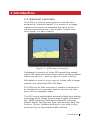
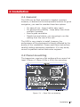
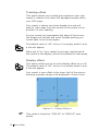
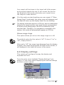
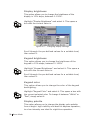
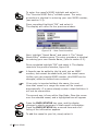
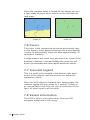
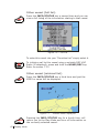
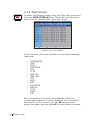
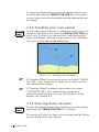
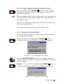
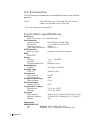
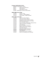
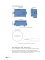
1
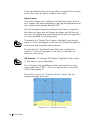
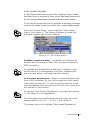
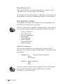
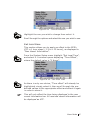
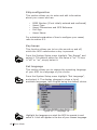
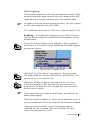
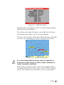
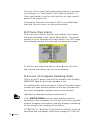
MANUAL SIMRAD AI50 Class B Transceiver 988-0168-003 Iss.3.0 English © 2007 Navico UK Ltd The technical data, information and illustrations contained in this publication were to the best of our knowledge correct at the time of going to print. We reserve the right to change specifications, equipment, installation and maintenance instructions without notice as part of our policy of continuous development and improvement. No part of this publication may be reproduced, stored in a retrieval system or transmitted in any form, electronic or otherwise, without prior permission from Navico UK Ltd. No liability can be accepted for any inaccuracies or omissions in the publication, although every care has been taken to make it as complete and accurate as possible. 2 Contents 988-0168-003 Iss.3.0 Sep 07 WP Contents 1 Introduction 1.1 General overview 9 9 1.2 About this manual 10 1.3 SimNet/NMEA2000 10 1.4 WR20 Remote (not supplied) 10 2 Installation 13 2.1 General 13 2.2 Panel mounting 13 2.3 Bracket mounting 14 2.4 GPS antenna 14 2.5 VHF antenna 16 2.6 Power/data cable 18 2.7 SimNet cable 18 2.8 SD card (not supplied) 19 3 Keypad Overview 21 3.1 Layout 21 3.2 PWR/Lights key (powering on/off) 22 3.3 Navigation keys 22 Display mode 22 Menu mode 22 Data entry mode 23 3.4 Zoom keys 23 3.5 ENTER/MENU 23 3.6 INFO/STATUS 23 3.7 TRACK/CLR TRK 23 Contents 3 3.8 HOME/DSC 24 3.9 VIEW/DISPLAY 24 3.10 PWR/ (backlight adjustment) 4 Menu Navigation 24 25 4.1 General operation 25 4.2 Navigation keys 25 4.3 Data entry mode 25 4.4 ENTER/MENU 25 5 Initial Configuration 27 5.1 Window display convention 27 5.2 Initial start up sequence 28 5.3 Ship configuration procedure 29 MMSI Entry 30 Vessel type entry 32 Vessel dimensions & GPS reference 32 Call sign entry 34 Vessel name entry 34 6 Menu Mode 35 6.1 General 35 6.2 Display mode settings 35 Coastline detail 35 Tracking offset 36 Display offset 36 Show range rings 37 6.3 Display settings Display brightness 4 Contents 37 38 Keypad brightness 38 Keypad color 38 Display palette 38 6.4 Favorites List 39 Adding an entry 39 Edit entry 41 Delete entry 41 6.5 Alarm setup 41 Collision alarms 42 Lost vessel alarms 45 Favorites alarm 46 6.6 System setup 46 Units of measure 46 Set local time 47 Ship configuration 48 Key beeps 48 Set language 48 Data logging 49 Transmit enable 51 Reset options 51 6.7 SimNet/NMEA2000 52 Data sources 52 Network management 53 Network list 54 Remote enable 54 DSC Radio select 54 6.8 Product info 55 Contents 5 7 AIS Map Mode 57 7.1 General 57 7.2 Vessel icon detail 57 7.3 Range rings/info 58 7.4 Point of view 59 7.5 Coast line detail 59 7.6 Cursor 60 7.7 Transmit legend 60 7.8 Vessel information 60 Own vessel 61 Other vessel’s info (reduced list) 61 Other vessel (full list) 62 Other vessel (minimal list) 62 7.9 Features for vessel information 63 7.10 Making a DSC call (map mode) 63 7.11 Text mode 64 Changing the sort order 65 7.12 Making a DSC call (text mode) 65 7.13 Tracking individual vessels 65 7.14 Tracking your own vessel 66 7.15 Clearing down all trails 66 7.16 Light adjustment (short cut) 67 7.17 KeyLock function 67 6 Contents 8 Alarms 69 8.1 General 69 8.2 Collision avoidance alarms 70 CPA/TCPA alarm 70 Lost vessel alarm (1) 72 Guard zone alarm 72 8.3 BIIT alarm 73 8.4 Lost vessel alarm (2) 73 8.5 Favorites alarm 74 8.6 Loss of compass heading data 74 8.7 Safety message alarm 75 9 Appendix 77 9.1 Maintenance 77 9.2 Troubleshooting 77 9.3 Accessories 78 9.4 Product specifications 78 9.5 Dimensions 80 9.6 Service and warranty 80 9.7 Declaration of Conformity (EU) 81 10 Index 83 Contents 7 Blank page 8 Contents 1 Introduction 1.1 General overview The AI50 is a collision warning device that has been designed for maximum safety. It is housed in a rugged waterproof enclosure to withstand the rigors of the marine environment and it has a bright, crystal clear, color display for easy viewing. Figure 1.1 - AI50 Class B Transceiver It displays the position of other AIS transmitting vessels within VHF range and allows other vessels and shore based stations to see you - even at night or in poor visibility. With safety in mind it is very easy to initiate calls to target vessels via a networked DSC VHF Radio. The AI50 can be flush mounted or bracket mounted and be located at any convenient position such as the helm pod or at the navigation table. The AI50 uses a sophisticated automatic digital time sharing technology which enable the exchange of static information like; MMSI (Maritime Mobile Service Identifier) Number, Vessel’s Name, Call Sign and Type. Also dynamic data like; Position, Course, Distance and more, from ship to ship, and from ship to shore based traffic stations. Introduction 9 The advantages of the AI50 are: • Increased awareness of the current shipping situation within your VHF range through the exchange of data between vessels. • Improving traffic management in busy shipping lanes through exchanging information between vessels and shore based traffic stations. • Reporting information automatically in shipping areas where it is mandatory. As with all electronic navigational equipment, it is only an aid to navigation and should not be used as a substitute for good seamanship. Remember - Maritime law requires that you keep a good lookout at all times. The position of a vessel on the screen is the position of the most recent transmission and may not be the current position. 1.2 About this manual The manual combines operating and installation information for the AI50. Operation is sub-divided into main working categories for easy reference. 1.3 SimNet/NMEA2000 SimNet is Simrad’s proprietary high speed data bus network complete with NMEA2000. It provides intelligent sharing of data and control information between a wide range of marine electronics and instruments. 1.4 WR20 Remote (not supplied) The WR20 Remote Commander is a handheld wireless command centre, which enables you to remotely control your AI50, as well as all of your other SimNet electronics, such as Plotters/Radar, Autopilots and Instruments. It will also control the VHF with the advanced features of voice 10 Introduction calls, and when paired to a mobile phone it offers the same operating features as a Bluetooth Handset. The WR20 Handset has been designed to survive the rigours of the marine environment. It has a tough, sealed body that is fully waterproof and houses an integral LiIon rechargeable battery that is automatically charged whenever it is placed in its cradle. ) For further information on the WR20 and other Simrad Products, visit our web site at www.simradyachting.com. Introduction 11 Blank page 12 Introduction 2 Installation 2.1 General The AI50 can be flush mounted or bracket mounted, however, to determine the best possible location for good navigation, you need to consider these few options: • • • • For ease of use - keep it within easy reach For good screen visibility - keep away from direct sunlight if possible Ensure good ventilation Decide how and where, you are going to run the cabling from the rear of the unit. The AI50 is very simple to install, however, the performance of the equipment is directly affected by the quality of the installation. Please read these instructions carefully before attempting installation. If in any doubt, consult a qualified marine electronics engineer. 2.2 Panel mounting The transceiver requires a flat surface with an area of at least 172mm x 115mm (6.8in x 4.5in) for mounting. Figure. 2.1 – Panel Cut-out drawing Installation 13 Allow sufficient space behind the unit for cable entry – at least 50mm (2.0in), in addition to the depth of the unit, is recommended. The surface should be rigid and sturdy enough to be able to support the weight of the unit, taking into account the shock loads likely to be encountered when the vessel is under way in heavy seas. 1 2 3 4 5 6 7 8 9 Remove the backing paper and stick the cutting template onto your console or panel where the unit is to be mounted. Drill a 2.5mm hole in each corner, where shown, to fasten the unit. Drill 8 x 6mm holes where shown to assist in cutting the case peripheral hole. Carefully cut the hole where shown on the template. Remove the template. Assemble case gasket to the rear of the AI50 unit. Place the AI50 unit in the cut-out and fasten with 4 self tapping screws into 2.5mm holes. Carefully remove 4 corners, (3 left and 3 right supplied), from the moulding rosette. (Note: they are numbered 1 and 2 on rear) Place the 4 snap fit, removable corner covers into place. (No.1 is placed in the bottom left and top right position, No. 2 is placed in the top left and bottom right position. 2.3 Bracket mounting Using the supplied bracket as a template, hold it against the surface it is going to be mounted on. With a marker pen, make a mark through the centre of the holes and drill a 3.5mm pilot hole on each mark. Secure to the surface with the supplied self tapping screws. 2.4 GPS antenna The antenna, ideally needs to be mounted as low as possible with a clear view of the sky to minimise 14 Installation errors due to movement over and above the transitory movement of the vessel. The GPS antenna is capable of being flush mounted on a suitable flat area of the cabin roof or deck area. In this configuration, fit the supplied rubber gasket under the antenna and use the four threaded studs, nuts and washers to fix the antenna down. ) The cable can be routed in the molding to drop down directly underneath, or by breaking out the thin traps, the cable can be routed out of the side of the antenna. Alternatively, the antenna may be fixed on a standard 1” threaded mounting pole (Not supplied). Attach the supplied mounting base to the antenna with the four screws, thread the cable down the center hole and through the pole. Thread the pole into the mounting base, before attaching the pole to the superstructure. ) DO NOT connect your antenna using further extension cables, or remove the connector, as this may degrade the reception to a point where it may not function correctly. To minimize interference, place the antenna in a position away from steel constructions, wires, metal masts, sources of electrical interference, such as radar etc. If installing the GPS antenna close to other antennas, mount it either above or below their radiation beams. The antenna cable is terminated in a push fit connector (SMB). Push the antenna plug firmly into the socket on the back of the AI50. The following drawing is a guide to the connections on the rear of the unit. Figure 2.2. Installation 15 Figure. 2.2 - Rear view connections ) 2.5 VHF antenna North American Users - To meet FCC (Federal Communications Commission) rules on Radio Frequency Exposure, it is recommended that the VHF antenna is mounted at least 3m (10ft) away from any area accessible to any personnel on board. If this distance is achieved by vertical separation, the antenna must be at least 5m (16.5ft) above deck. This guideline applies only to antennas not exceeding 3dBi gain. Failure to observe these recommendations may expose those within the MPE (Maximum Permitted Exposure) radius of 1m (3ft) to RF absorption levels that exceed the FCC safe limits. The most important factor in the performance of any AIS transceiver will be the quality and positioning of the antenna. As the range of VHF signals are governed by line of sight, the antenna should be placed as high as possible, while remaining clear of any metallic objects. Long whip antennae are generally recommended for larger boats, although the most popular antennae for marine use is 1m (3ft 3in) long. On sailboats these are 16 Installation usually mounted on the masthead, where the length of the antenna keeps it clear from the navigation lights and wind vanes. This type of antenna can also be mounted on the cockpit roof or powerboat garages. For maximum range, it is recommended that a VHF antenna specifically tuned for use with an AIS is used, and mounted away from the standard VHF antenna. Vertical separation is preferred, but where this is not practical, at least 5 metre horizontal spacing is recommended The antenna coaxial cable and any connectors used must be rated at 50Ω. Under no circumstances should standard domestic TV cable and connectors be used. Incorrectly rated cabling and connectors could result in power not reaching the antenna, but also power could be reflected back into the AI50 unit, reducing its performance. The quality of any connections and integrity of the cable will directly affect the performance of the radio. Poor soldering or corrosion of the terminals can impair performance. We recommend that screw or crimp terminal type connectors are not used for any through deck fittings - a good quality waterproof solder terminal connector will be less susceptible to poor connection due to corrosion of the contacts. To ensure the best performance of the radio, the antenna cable should be routed where it is least likely to interfere with, or receive interference from other electronic equipment, such as echo sounder transducer cables and high current carrying cables. The antenna cable should terminate in a standard marine PL259 plug fitting. Connect the antenna plug to the socket on the back of the AI50 and screw the retaining collar down. Figure 2.3. Installation 17 Figure 2.3 - VHF Antenna connection ) To avoid possible water damage to the transceiver, it is recommended that all cables are looped to provide a drip path. 2.6 Power/data cable Power cable The electrical installation is quite straightforward - push the connector end of the supplied Power/Data cable firmly into the socket on the rear of the unit. The Power cable has two wires, one red and one black. Connect the red cable to +12V via a 2 Amp fuse, and the black cable to 0V. Data cable The data cable is used for connectivity to AIS enabled chart plotters with NMEA0183-HS interface. The Data cable is screened and has four wires. For connection data refer to the following table. Signal Color Out +ve Orange Out -ve Blue Comment In +ve Yellow Not Used In -ve Green Not Used Figure 2.4 - NMEA0183-HS connections ) 18 Installation (NMEA0183-HS is specified at 38.4kbaud and is not compatible with conventional NMEA0183, which operates at the lower speed of4800baud) 2.7 SimNet cable The AI50 is connected to the SimNet databus using the cable supplied. Ensure that the connector on the end of the cable is in the correct orientation and press firmly into either of the two sockets on the rear of the unit. Figure.2.2. The spare socket can be used to daisy chain SimNet to another item of equipment. If the spare socket is not used insert the supplied blanking plug. 2.8 SD card (not supplied) The SD card slot is situated on the reverse of the unit under a water resistant cover. Figure. 2.5 - SD Card Access Cover ) DO NOT insert or remove the SD card while the AI50 is turned on. Locate and undo the two retaining screws, and carefully remove the cover to reveal the SD card slot. With the SD card, contact side down, place under the shroud and slide firmly into place, making sure the card is sitting squarely and not at an angle. Installation 19 Replace the cover and screw back into place, making sure not to over tighten the screws. ) 20 Installation The use of high speed SD cards is not recommended. Use only Class 1 SD cards. 3 Keypad Overview 3.1 Layout 1 2 3 4 5 9 8 7 6 Figure 3.1 - AI50 Automatic Identification System Keypad functions 1 2 3 4 5 6 7 8 9 ) 8-Way NavPad ENTER/MENU INFO/STATUS HOME/DSC PWR/ (Lights) VIEW/DISPLAY TRACK/CLR TRK + Zoom Out Zoom In To obtain the functions printed on the keys in white text, requires a single push of that key. To obtain the functions printed on the keys in red text, requires you to press and hold that key for a couple of seconds. Keypad Overview 21 3.2 PWR/Lights key (powering on/off) To turn on the AI50, press and hold the PWR/ approximately 0.25 seconds. ) key for When turning your AI50 on for the first time, you will be directed to configure it for full use. If this is declined the AI50 will only function as a receiver until fully configured. (Refer to chapter 5). Press and holding the PWR/ key, will power the unit down. A brief message will appear until the unit turns off. Figure 3.2 - Power down message 3.3 Navigation keys The circular 8-way NavPad, (Figure 3.1 Item 1) can operate in a variety of ways depending on which mode the unit is in. Display mode The NavPad keys are used to position the cursor around the screen. By using a combination of keys, for example, pressing S and W together, will make the cursor move diagonally up and to the left. Menu mode The ST keys are used to highlight menu items before selecting them. The X key is used to select a new menu item, or go further into an item’s sub menu. A single press of the W key returns you to the previous menu or mode. Press and hold the W key returns you to the Display Mode 22 Keypad Overview Data entry mode During data entry, the NavPad keys are used to highlight characters and numbers before using the ENTER/MENU key to select them. 3.4 Zoom keys + In Map Mode these keys have two functions: • A short single press, will increase or decrease the range shown in the display about your current position. • Press and holding, will increase or decrease the range shown in the display about the cursor. 3.5 ENTER/MENU Pressing the ENTER/MENU key in any display mode, will select “Menu Mode” and display the menu in the top left corner. When navigating within a menu, once an item has been highlighted, pressing the ENTER/MENU key or the X key, will select that item or sub menu. In data entry mode the ENTER/MENU key is used to enter that data into the systems memory. 3.6 INFO/STATUS STATUS INFO A short press allows you to view the received information of a vessel that has been highlighted using the cursor. Press and holding the INFO/STATUS key will show your own vessel’s information in a column on the right side of the display. 3.7 TRACK/CLR TRK CLR TRK TRACK The AI50 can show the track of a selected vessel. A single press of the TRACK/CLR TRACK toggles the tracking of a vessel on/off. Press and holding, will clear all displayed tracks. Keypad Overview 23 3.8 HOME/DSC Resets the view and your own vessel’s position to the centre of the display, or the offset position if activated. Press and holding the HOME/DSC key initiates a DSC call, to a highlighted vessel, via an installed, compatible SimNet VHF radio. 3.9 VIEW/DISPLAY Toggle between views (HEADUP, NORTHUP, COGUP). DISPLAY VIEW DISPLAY VIEW Press and hold VIEW/DISPLAY to access Text Mode in which the map is replaced by a list of target vessels and their details. While in Text Mode, short presses of the VIEW/DISPLAY key will cycle through the predefined order in which the vessels are sorted. Press and hold again to restore map view. 3.10 PWR/ (backlight adjustment) Short presses of the PWR/ preset lighting levels. key will cycle through the Figure 3.3 - Display and Keyboard brightness message 24 Keypad Overview 4 Menu Navigation 4.1 General operation Throughout this manual, the following convention will apply to the way you navigate the AI50 menus, and select and change the user settings. 4.2 Navigation keys To find your way around the AI50 menus, you mostly use the NavPad keys and the ENTER/MENU key. The ST keys are used to highlight items in the menu list before selecting them. A single press of the W key returns you to the previous menu or mode. Press and hold the W key will return you to the Map Mode. All user setup data, falls into one of the following categories: • • • Tick box Pre-defined list Alpha/numeric entry 4.3 Data entry mode During data entry, the ST keys are used cycle through a pre-defined list before selecting a value, or used in conjunction with the WX keys, to move around the alpha/ numeric characters on the screen. For example, during vessels configuration, such as MMSI, vessel name and callsign entry. 4.4 ENTER/MENU Pressing the ENTER/MENU key in any display mode, will select “Menu Mode”. The top level menu, will appear in the top left hand corner of the display. Menu Navigation 25 or X The ENTER/MENU key or the X key, is then used to go further into a highlighted menu or sub menu, or to select an item in that menu. Once a change has been made, pressing ENTER/MENU saves that change to the AI50’s memory. With a tick box, the ENTER/MENU key simply turns the option on or off, (ticked or un-ticked). 26 Menu Navigation 5 Initial Configuration 5.1 Window display convention Throughout the operation of the AI50 all displays will conform to the following convention for daylight settings: Title bar: This is the top bar of a window, and will display the title or type of warning/alarm being displayed. In information and menu windows the Title Bars will be “Blue”. In general alert windows it will be “Yellow and in windows displaying serious alarms, it will be “Red”. Information area: The middle portion of the window will show the information/menu or graphic relevant to the title displayed and will be grey. Instruction bar: The lower bar in the window is known as the “Instruction Bar”. This bar will inform you of what action to perform, relevant to the information being shown, and will normally be “White”. For general alerts it will be “Yellow” and for serious alarms it will be “Red”. Initial Configuration 27 5.2 Initial start up sequence When you turn your AI50 on for the first time, you will be prompted to select the language you want the unit to work in. Highlight your choice and select it. The default is “English”. Figure 5.1 – Select language Once selected, press ENTER/MENU to continue. The display changes to show a warning regarding good seamanship. Figure 5.2 - Start Up Screen Press W to clear this window and continue. If you have not previously configured the unit, a new Information window appears asking if you wish to configure the AI50 for full operation now. The default value is “Yes”. Figure 5.3 - Configuration request 28 Initial Configuration If you wish to configure your AI50 now, select “Yes”, then go to section 5.3. If not, select “No”. If you select “No” the following message will be displayed. Figure 5.4 – Configuration warning Press W to exit the configuration menu and return to Map mode. If you decide not to enter your MMSI at this stage, it can be entered later from within the System setup menu, refer to section 6.6. However, you will not be permitted to enter any other information about your vessel until MMSI entry has been completed. ) Your AI50 will only operate as a receiver, until you have fully completed the ship configuration as described in Section 5.3. 5.3 Ship configuration procedure From Map Mode, select Menu Mode, scroll down the menu and select “System Setup”. Scroll down to “System Setup” menu and select “Ship Configuration”. A more detailed procedure is explained further on in this chapter. All values selected during this procedure will be automatically stored in the AI50 memory once completed. All data entered during this procedure can be edited at any time, except the MMSI. Once this has been entered and confirmed it will become locked and shown as greyed out. Indicating that it can be viewed, but not edited. Initial Configuration 29 Should it become necessary to change your MMSI, for example, if you wish to re-install your AI50 into a new vessel; you will need to contact your local Simrad dealer about reprogramming a new number. MMSI Entry If you have selected "YES" when asked to “Configure Now”, a warning window will appear. Figure 5.5 – MMSI Entry warning Press the W key to clear the message and continue. The warning disappears from the screen and you are now ready to enter your MMSI number. Figure 5.6 – MMSI Entry display Using the NavPad keys, highlight the first number of your MMSI and press the ENTER/MENU key to select it. The first number appears in the display and the cursor moves on to the second. Repeat this procedure until every number has been entered. If you have made an incorrect entry, highlight "" or "" and pressing ENTER/MENU, move the cursor onto the position of the error. Highlight the correct number and select it. Once you are sure that your MMSI number is correct, highlight “OK” and select it to save it. ) "OK" will only function if all digits have been entered. Once your MMSI number has been entered, the entry 30 Initial Configuration screen will change, this time the title bar will read “Confirm MMSI Entry”. You must now repeat the above entry procedure to confirm your MMSI entry. Once you are sure that your confirmation is correct, highlight “OK” and select it to save it. If both entries are identical the following message will be displayed confirming a successful entry. Figure 5.7 - MMSI Confirmation Clearing this message will take you to the “Vessel Configuration Information” window, where you can continue entering the remaining ships configuration information. If the two entered MMSI numbers do not match, a message indicating this will be shown. Figure 5.8 - MMSI mismatch warning Clearing the display will revert you back to the Configuration Request window as shown in Figure 5.3 to start again. If you need to cancel the input mode, highlight the “CANCEL” button and select it. A warning will be shown in the display. Figure 5.9 - MMSI cancelled warning Clearing the display will revert you back to the Configuration Request window as shown in Figure 5.3. Initial Configuration 31 Once the MMSI number has been entered and confirmed, the next stage of the configuration is highlighted. The MMSI number is now shown as greyed-out and locked into the system memory; no further changes can be made to it except by an authorised agent. Figure 5.10 – Vessel configuration list Vessel type entry Highlight “ Vessel type” and select it. The default value, “Not Set” will be highlighted. Figure 5.11 – Vessel Type Entry Screen The available choices for vessel type are: • • • • • • • • • Not Set (default) Pleasure Craft Sailing Vessel Military Diving Ops Dredging Tow Large Load Towing Fishing When you have made your choice, select it to save it into the AI50’s memory. Vessel dimensions & GPS reference Select “Vessel Dimensions & GPS Reference”. A window opens showing the required dimensions. 32 Initial Configuration Figure 5.12 – Vessel Dimensions & GPS Reference Entry Screen All numeric entries must include preceding zero’s. For example if “Dim A “ is 20 metres, it should be entered as “020” and not “20” before “OK” is selected, if not the following message will appear. Figure 5.13 - Dimension entry error Enter the required dimensions of your vessel, (in metres), with reference to the GPS antenna, using the same method of entry as described during MMSI entry. Once you have entered a dimension, the cursor will advance to the next one. When complete, highlight "OK" and select it to accept your entry. The display returns to the vessel configuration Information window. If you have made an incorrect entry, use the same method to correct it as described in “MMSI Entry” earlier in this section. Initial Configuration 33 Call sign entry Selecting “Call Sign” will open a window allowing you to enter you vessels callsign. Figure 5.14 – Call Sign Entry Screen Enter your callsign using the same method of entry as described during MMSI entry. When complete highlight “OK” and select it to save it. If you have made an incorrect entry, use the same method to correct it as described in “MMSI Entry” earlier in this section. Vessel name entry Select “Vessel Name”. A window opens identical to the call sign entry window, figure 5.14 but with “Vessel Name Entry” in the title bar. Enter your vessel’s name using the same method of entry as described for “MMSI entry”. When complete highlight the OK button and select it to save it. Once the Vessel Name has been entered, the display returns to the Vessel Configuration Information menu. Figure 5.15 – Completed vessel configuration Ships Configuration is now complete and stored in the unit’s memory ready for use. 34 Initial Configuration 6 Menu Mode 6.1 General The AI50 has many advanced features that are user configurable. These options can be accessed by pressing ENTER/MENU during any display mode. A window opens in the top left corner displaying the Main menu options. Figure 6.1 – Menu Mode Display 6.2 Display mode settings This section will change the way the display looks when in operation. From the Main menu highlight “Display Mode” and select it. A sub menu opens displaying various options and their current status. Figure 6.2 – Display Mode Options Coastline detail This option allows you to turn the coastline detail on and off. or X The default value for this option is “on”, and a tick is shown in the box. To change its value simply select it. The coastline map is a visual aid to assist with orientation and range. It is not a marine chart and must not be used as a substitute for accurate charting Menu Mode 35 Tracking offset This option allows you to track the progress of your own vessel in relation to all other AIS equipped vessels within your VHF range. Your vessel is shown as a boat shaped icon and will start to track away from the centre of the screen in the direction of your heading. As your vessel icon approaches the edge of the screen, the display will refresh and scroll forward putting your vessel back to the centre again. The default value is “off”, to turn it on simply select it, and a tick will appear. or X When set to “on” your vessel is no longer maintained at the centre of the display, and will be allowed to track away. Display offset or X This option allows you to turn the display offset on or off. The default value is “off”, to turn it on simply select it, and a tick will appear. Your vessel is now offset to the lower half of the screen, allowing a greater range to be displayed in front of you. Figure 6.3 – Display Offset on ) 36 Menu Mode This mode is limited to “COG-UP” or “HDG-UP” view points. Your vessel will be shown in the lower half of the screen and pointing towards the top. It will remain like this for the duration of this mode, and when your vessel turns, the map will rotate about it. ) ) If in this mode you start tracking your own vessel, if “Show Range Rings” is activated, the range rings will disappear and the boat will move up the display under its own heading. The display could also work for a COG-Up, but the relationship between the vessel and the map might not be representative of actual events taking place, due to the influences of the wind and tide. Therefore, if no compass is connected to the system, this mode will automatically appear as COG-Up. Show range rings This option allows you to turn the range rings on or off. The default option for this value is “off”. To turn it “on” or “off”, simply select it. or X When set to “off”, the range rings disappear from the display, however, the overall range across the width of the screen, is still displayed in the lower left corner of the screen. 6.3 Display settings This section will configure the way the display and keyboard will look. or X From the main menu highlight “Display Settings” and select it. A sub menu opens displaying the various settings and their current values. Figure 6.4 – Display settings menu Menu Mode 37 Display brightness This option allows you to change the brightness of the display in 10% steps, between 0-100%. Highlight “Display Brightness” and select it. This opens a box with the current value in. or X Figure 6.5 – Changing display settings Scroll through the pre defined values for a suitable level, then select it. Keypad brightness This option allows you to change the brightness of the keypad in 10% steps, between 0-100%. Highlight “Keypad Brightness” and select it. This opens a box with the current value in. or X Scroll through the pre defined values for a suitable level, then select it. Keypad color This option allows you to change the color of the keypad backlighting. or X Highlight “Keypad Color” and select it. This opens a box with the current selected color. To change it between “White” or “Red”, simply select it. Display palette This option allows you to change the display color palette from a bright high visibility one ideal for daytime operation, to a low intensity one ideal for night time operation. 38 Menu Mode or X Highlight “Keypad Palette” and select it. This opens a box with the current selected palette. To change it between “Day” or “Night”, simply select it. 6.4 Favorites List Vessels can be added to a “Favorites List” and an alarm set, so that you receive an alert when a vessel on your list comes within VHF range. (To set the alarm, refer to section 8.5). There are two methods for adding vessels to your list. Adding an entry or X The first way to add an entry is from the main menu. Highlight “Favorites List” and select it. A window will open showing the current list of favorites. Figure 6.6 - Favorites list (non selectable) or X Highlight “Add New Favorite”, and select it. The display changes showing the two available data entry fields, “MMSI” and “Vessel Name”. Figure 6.7 – Adding a Favorite Menu Mode 39 or X To enter the vessel’s MMSI highlight and select it. The “Favorite MMSI Entry” window opens. The entry procedure is identical to entering your own MMSI number, (see section 5.3). Once completed highlight “OK” and select it. The display will return to the previous window. or X Figure 6.8 – New Favorite added or X Next, highlight “Vessel Name” and select it. The “Vessel Name Entry” window opens. The entry procedure is identical to entering your own Vessels Name, (refer to section 5.3). Once completed highlight “OK” and select it. The display reverts to the previous window, figure 6.8. ) ) A favorite can be added to the list with just an MMSI number, but cannot be added with just the vessel name. Unlike your own vessels MMSI number, this MMSI can be changed, edited or deleted once entered. If an entry is inserted without the name, the next time that vessel is in range the name will be inserted automatically. If a name already exists in that field then it will not be overwritten. The second way is from within Map Mode. Place the cursor over the selected vessel, and a highlighted box will appear. STATUS INFO or X 40 Menu Mode Press the INFO/STATUS key once, and the display changes to show a summary of that vessel’s information. Press the INFO/STATUS key a second time and a full listing of the information appears. To add this vessel to your list, simply select it. Edit entry From the Favorites List highlight “Select Favorite” and select it. or X Highlight the vessel you wish to edit and select it. A menu window opens with the available options. Figure 6.9 - Editing a Favorite Highlight the field you wish to edit and select it. or X Editing the MMSI number is described in section 5.3 and editing the Vessel Name is described in section 5.3 Delete entry From the Favorites List, highlight “Select Favorite” and select it. Highlight the item you wish to delete and select it. or X A window opens showing three choices “MMSI”, “Vessel Name” and “DELETE”. Highlight “DELETE” and select it. or X 6.5 Alarm setup This section allows you to activate/deactivate, and setup parameters of the various safety alarms on your AI50. For detailed information about alarm messages, please refer to section 8. Menu Mode 41 From the main menu highlight “Alarm Setup” and select it. A sub menu opens displaying the various types of alarms. or X Figure 6.10 – Alarm list Highlight the Alarm type you wish to activate or change and select it. Collision alarms The AI50 has three types of alarms to help prevent a collision at sea, they are • • • or X CPA/TCPA Guard Zone Lost Vessel Alarm From the “Alarm Setup” menu highlight “Collision Alarm” and select it. A window open showing the activation status and values. The default is “Not Active “. Figure 6.11 – Collision Alarms CPA/TCPA - When you activate the CPA/TCPA Alarm from within the Alarm Setup Menu, the CPA/TCPA will be calculated for all AIS equipped vessels in your VHF range. ) 42 Menu Mode CPA – Closest Point of Approach is the calculated distance of how close a vessel will pass. TCPA – Time to Closest Point of Approach is the calculated time to reach the CPA Calculations are made on the basis of vessels continuing on their latest COG and SOG. When both the CPA and TCPA values calculated by the AI50 are less than, or equal to the values set by the user, then an alarm will sound, and a warning will be displayed. The CPA/TCPA values are set by the user, as described above. It is the responsibility of the user to determine how close another vessel may pass without being dangerous, and how quickly the user can react to manoeuvre their own vessel to avoid a collision. or X To activate the “CPA/TCPA” alarm, highlight it and select it. A tick appears in the box, indicate the alarm is now active and using the values shown. Highlight the “CPA Value” you wish to change, then select it. Figure 6.12 - CPA/TCPA values or X Scroll through the predefined values and select the most appropriate one, (30ft – 8.1nm or equivalent in selected units), then select it. The cursor returns to highlight “CPA Value”. To change “TCPA Value”, highlight it and select it. The value is now highlighted. or X Scroll through the predefined values and select the most appropriate one, (5 min – 95min), then select it. The cursor returns to highlight “TCPA Value”. Menu Mode 43 If the calculated values are less than or equal to the values set by the user, an alarm condition will exist. Guard zone This option allows you to setup an invisible perimeter around your vessel, that when activated, a red ring will appear around your vessel in the display, labelled “GZ”. Any AIS equipped vessel at a distance less than, or equal to the value you have set, will trigger an alarm, and its icon will turn red. An audible and visual warning will also be triggered if you have enabled it on during setup. or X To activate the “Guard Zone” alarm, highlight it and simply select it. A tick will appear in the box, to indicate the alarm is now active and using the values shown. To activate the “Audible/Visual Warning”, highlight it select it. A tick will appear in the box, to indicate the alarm is now active. GZ Radius - To change “GZ Radius” highlight it then select it. The value is now highlighted. or X Scroll through the predefined values and select the most appropriate one, (35ft. – 27nm or equivalent in selected units), then select it. The cursor returns to “Collision Alarms” menu and the display changes as shown. Figure 6.13 – Guard Zone active 44 Menu Mode Lost vessel alarms A Lost Vessel Alarm occurs when the reception from a vessel has been lost for a period of time, which has been determined by its missed transmission periods and last known speed. This function allows the user to activate a warning message each time a vessel is lost from within the current display range. or X From the “Alarm Setup” menu highlight “Lost Vessel Alarm” and select it. The display changes to show the activation status and current setting. Figure 6.14 – Lost Vessel Alarm Audible/visual warning - if enabled, will activate an audible and visual alarm each time a vessel is lost from AI50 reception. or X To activate the “Audible/Visual Warning”, highlight it and simply select it. A tick appears in the box, indicating the alarm is now active, and using the value shown. Lost vessel persistence - When a vessel has been lost from AI50 reception, its icon will change to a lost vessel icon. Refer to section 7.2. Lost vessel persistence is the user assignable time period for which this lost vessel icon will remain on the screen. To change “Lost Vessel Persistence”, highlight and select it. The value is now highlighted. or X Scroll through the predefined values and select the most appropriate one, (1 min. – 30 min.), then select it. The cursor returns to highlight “Lost Vessel Persistence”. Menu Mode 45 Favorites alarm This option allows you to be notified if a vessel in your “Favorites List” comes within VHF range. To activate the “Favorites Alarm”, highlight it and select it. A tick appears in the box, indicating the alarm is now active. 6.6 System setup This section is where you customise the configuration of the AI50 to function how you want. From the Main menu highlight “System Setup”, and select it. A sub menu window opens showing the following choices: or X • • • • • • • • Units of Measure Set Local Time Ship Configuration Key Beeps Set Language Data Logging Transmit Enable Reset Options Units of measure This section allows you to change the units the AI50 displays, for both for distance and speed. The options are as follows: or X 46 Menu Mode • Distance in: Nautical Miles (default) Miles Kilometres • Speed in: Knots (default) MPH KPH From the System Setup menu highlight “Units of Measure” and select it. A window opens showing two choices, “Distance” or ”Speed units”. Figure 6.15 - Units of Measure Highlight the one you wish to change then select it. or X Scroll through the options and select the one you wish to use. Set local time This section allows you to apply an offset to the GPS’s UTC in 1 hour steps, (-13 to +13 hours), as displayed in “Own Vessel Information”. or X From the System Setup menu highlight “Set Local Time”, and select it. A window opens displaying “Time Offset”, where the default value is “0 Hours”. Figure 6.16 – Set Local Time or X ) As there is only one choice, “Time offset” will already be highlighted, simply select it, then scroll through the predefined values to the appropriate offset and select it again in order to store it. This will only affect the time being displayed in the own vessel information bar. All received vessel information will be displayed as UTC. Menu Mode 47 Ship configuration This section allows you to enter and edit information about your vessel such as: • • • • • MMSI Number (If not initially entered and confirmed) Vessel Type Vessel Dimensions and GPS Reference Call Sign Vessel Name For a detailed explanation of how to configure your vessel, refer to section 4.3. Key beeps This function allows you to turn the sound on and off, which the AI50 makes when a key is pressed. or X From the System Setup menu highlight “Key Beeps”, and select it. The default option for this value is “on”. To turn it “off” or “on”, simply select it. Set language This section allows you to change the operating language of your AI50 to a language of your choice. or X From the System Setup menu highlight “Set Language”, and select it. The display changes to show a list of available languages, with English being the default choice. Figure 6.17 – Language list or X 48 Menu Mode Highlight the language you wish the AI50 to operate in and select it. A tick will appear in the box of your chosen language. Data logging This function enables you to store an electronic record, of the dynamic and static data received from all vessels within VHF range during a voyage, including your own vessel’s data. ) In order to use the Data Logging function, you will require an SD card installed into your AI50. For installation procedure of SD card, refer to section 2.8. Enabling - To enable data logging on your AI50, first you have to select a data file name that the information will be stored under. or X From the System Setup menu highlight “Data Logging”, and select it. A window opens displaying the data logging options as shown. Figure 6.18 – Logging menu or X or X ) Highlight “Log File Name” and select it. Scroll through the predefined file names, (AISLOG1 to AISLOG10), and select the one you wish to use. Highlight “Enable Logging” and select it to turn it on. A tick will appear in the box and the file name will be greyed out. All data for your voyage will now be stored under this file name. If you enter this menu with a log file open, you will only be able to end logging. When you press the W key to return to the previous menu, a pop-up window will inform you that the file has been created. Logging is now enabled, and all information being received will be recorded onto the installed SD card, under the selected file name. Menu Mode 49 If, however, you have omitted to fit an SD card into your AI50, or you have a non compatible SD card, when you try to enable logging the following message will be shown in the display. Figure 6.19 – Logging failure or X Disabling - From the System Setup menu highlight “Data Logging” and select it. A window opens displaying the options as shown previously in figure 6.18. Highlight “Enable Logging” and select it. The tick disappears and the file name above is no longer greyed out. or X ) When you press the W key to return to the previous menu, a pop-up window informs you that the file is OK. If the data logging is not disabled correctly before powering down, all data could be lost. Disabling a log file will not delete any of the data stored on it. Playback log - To playback a data log on your AI50, you have to select the correct data file name for the voyage you wish to replay. or X or X From the System Setup menu highlight “Data Logging” and select it. A window opens displaying the options as shown previously in figure 6.18. Highlight “Log File Name” and select it. The “File Name” is now highlighted. Scroll through the predefined file names until you find the one you wish to replay, then select it. Highlight “Playback Log” and select it to turn it on. A tick will appear in the box and the file name will be greyed out. or X 50 Menu Mode On exiting, the following message will be displayed, confirming playback is enabled and a log file is now open. Figure 6.20 – Logging Confirmed ) If you enter this menu with a log file open, you will only be able to end playback. Transmit enable This option allows you to turn the AI50’s VHF transmitter “on” or “off”, rendering you either visible or invisible to other AIS equipped vessels in your VHF range. or X From the “System Setup” menu highlight “Transmit Enable” and select it. The default value for this option is “On”. To turn it “off” or “on”, simply select it. Reset options Selecting this option will reset all system variables back to their factory default settings, except for the ship’s configuration. or X From the System Setup menu highlight “Reset Options” and select it. A window opens showing “Reset Options” already highlighted. Figure 6.21 – Reset Option or X To continue with a system reset, select it, and a tick will appear in the box. Highlight “CONFIRM” and select it. A window will open confirming that the system has been reset. Figure 6.22 Menu Mode 51 Figure 6.22 – Reset Confirmed 6.7 SimNet/NMEA2000 From the Main menu highlight “SimNet/NMEA2000” and select it. A window opens showing the following choices: • • • • • Data Sources Network Management Network List Remote Enable DSC Radio Select Data sources This section allows you to select a SimNet/NMEA2000 data source, to provide compass heading information. ) The data source must be able to supply magnetic compass heading. From the “SimNet/NMEA2000” menu, highlight “Data Source” and select it. or X As there is only one choice, “Heading” will already be highlighted, simply select it. Figure 6.23 – Data Source menu Scroll through the available SimNet data sources to the one of your choice and select it. or X 52 Menu Mode Network management This section allows you to manage all of the SimNet networks on your vessel, as well as all of the SimNet devices you have connected to those networks. From the SimNet/NMEA2000 menu highlight “Network Management” and select it. or X The Network Management window opens showing “Device Instance” and “System Instance” Device instance - This option will normally be used on large complicated systems, where there maybe more than one radio system or AIS on the same SimNet bus. For example, the system may contain more than one AI50. To prevent conflict across the network, these can each be assigned a unique device number between 0 and 255. Figure 6.24 – Device Instance or X From the Network Management menu, highlight “Device Instance” and select it. Scroll through the pre-defined numbers to the one of your choice, and select it to enter it into memory. System instance - A SimNet system can have a maximum of 50 devices or “Nodes” attached to it. If a large vessel has a requirement for more than 50 nodes, then a multiple network system is required. The system Instance allows the user to allocate a unique number between 0 and 15 to each network, which allows the multiple networks to intercommunicate. Menu Mode 53 If your vessel is large enough that it is likely to require setting up multiple networks, it is strongly advised that you contact Simrad Technical Support to discuss you particular system requirements before proceeding further. or X From the Network Management highlight “System Instance” and select it. Scroll through the pre-defined numbers to the one of your choice, and select it to enter it into memory. Network list This function displays all products connected to the SimNet/NMEA2000 network. From the SimNet/NMEA2000 menu highlight “Network List”, and select it. The Network List window opens, showing a list of all the products connected to the SimNet Network. Remote enable This option allows you to “Enable” or “Disable” the Simrad WR20 Remote Commander handset from controlling the AI50. From the “SimNet/NMEA2000” menu highlight “Remote Enable” and select it. or X The default value for this option is “enabled”, and a tick is shown in the box. To change it between “enable” or “disable”, simply select it. DSC Radio select If a compatible DCS radio is installed on the SimNet network, the AI50 will enable the user to initiate a DSC call. ) or X DSC functions will only be available, if the MMSI number has been entered into the radio. From the SimNet/NMEA2000 menu highlight “DSC Radio Select”, and select it. A window opens showing the DSC Radio Select menu and current option. As there is only one menu item simply select it. Scroll through the list of DSC radios to the one of your choice and select it. or X 54 Menu Mode If no radio is present on the SimNet network then “N/A” will be shown in the radio list. 6.8 Product info This section will display information about your AI50’s Unique Identifier, Software version and Ship Configuration information. or X From the Main menu select “Product Info” and select it. A window opens showing the first page of information, to view the second page, press the W key. Figure 6.25 – Product Info 1 Figure 6.26 – Product Info 2 Menu Mode 55 Blank page 56 Menu Mode 7 AIS Map Mode 7.1 General This section will describe the operational features of the AI50 Map Mode. Display orientation Range Rings Selected Target Vessels, heading & COG Own Vessel Coastline map Transmit Legend Display range Figure 7.1 – AI50 Display If the unit is returning or entering the Map mode from any other display mode, the last settings remain valid. 7.2 Vessel icon detail The AI50 displays different icons for each vessel state, they are as follows: Standard icon Tracked icon (Bold) Lost vessel icon ) Your COG will be shown as a dashed line emanating from the centre of your vessel’s icon, whilst the line coming from the front of the arrow head will be your heading. If a vessel displaying one of these icons goes into an alarm state, then the icon will turn red. AIS Map Mode 57 7.3 Range rings/info The Range rings consist of three concentric circles situated around the centre point of the display. The screen range information is shown in the bottom left hand corner of the display, as shown in Figure 7.1; this indicates the range across the whole display. The display range can be adjusted by using the zoom keys, with each circle displaying its range information on the left radial intersect point. Pressing the right hand zoom key, (zoom out), increases the range across the display. + Pressing the left hand key (zoom in), decreases the range across the display. If you wish to zoom in or out on vessels in a particular area of the display, place the cursor on your selected area, then press and hold either of the zoom keys. The display will zoom in or out at that point, depending on which zoom key is pressed. If your own vessel is still in view it will be shown as a small circle. You can set your screen to display any of the 12 ranges, they are: No. 1 2 3 4 5 6 7 8 9 10 11 12 58 Display Mode Range (between rings) Total Range (Across display) (Showing own Full display vessel info bar) 0.01nm 0.02nm 0.05nm 0.1nm 0.2nm 0.5nm 1.0nm 2.0nm 4.0nm 8.0nm 16.0nm 32.0nm 0.08nm 0.16nm 0.4nm 0.8nm 1.6nm 4.0nm 8.0nm 16.0nm 32.0nm 64.0nm 128.0nm 256.0nm 0.06nm 0.12nm 0.3nm 0.6nm 1.2nm 3.0nm 6.0nm 12.0nm 24.0nm 48.0nm 96.0nm 192.0nm 7.4 Point of view The AI50 can display information in one of three ways; “NORTH UP”, “HEAD UP” and “COG UP”. The symbol in the top left corner of the display informs you of your current view. ) DISPLAY VIEW HDG UP will only be available if a compass source is present. Pressing the DISPLAY/VIEW key, will cycle through the available options; “NORTH UP”, “HEAD UP” and “COG UP”. As you cycle through the options, the full name will be displayed in the top left corner for 2 seconds before changing to an arrow with a relevant letter in, denoting your selected view, “N”, “H”, and “C”. NORTH UP – Arrow on the display points to True North. 2 Secs HDG UP – Arrow on the display points to the vessels True Heading. 2 Secs COG UP – Arrow on the display points to the vessels COG True. 2 Secs Figure 7.2 – View Modes The “HDG Up” option will only be available when the unit is interfaced to a suitable source of Compass Heading information through the SimNet port. 7.5 Coast line detail The coast line detail is drawn from internally stored worldwide maps. It can be toggled on/off from within “Display Mode” options in the Main Menu, see section 6.2. The coastline map is a visual aid to assist with orientation and range. It is not a marine chart and must not be used as a substitute for accurate charting. Display Mode 59 When the coastline detail is turned off the display will turn a light shade of green which should not be confused with land mass. Figure 7.3a - Coastline detail on Figure 7.3b - Coastline detail off 7.6 Cursor The cursor is the intersecting horizontal and vertical lines on the display, which appear whenever the 8-way NavPad is used. It automatically times out after approximately 30 seconds of inactivity. A single press of any cursor keys will move it by 1 pixel in the direction of that key. Press and holding the cursor key will allow it to accelerate and move rapidly across the screen. 7.7 Transmit legend This is a small circle situated in the bottom right hand corner of the display, and informs the user about the transceiver status. When the AI50 starts to transmit your vessels data, the transmit legend will turn green for 1 second. If there is an internal fault it will turn red, with an indication of the fault, all other times it will be white. 7.8 Vessel information The AI50 is able to view information from any AIS equipped vessel within VHF range. 60 Display Mode Own vessel STATUS INFO Press and hold the INFO/STATUS key for 2 seconds, the display changes to show your own vessels information in a panel on the right side of the screen. Heading data source Own vessel heading or COG if no compass available Lat/Long Heading reference MAG or TRUE Current time Collision alarm setting COG & SOG Guard zone setting Figure 7.4 – Own Vessel Information STATUS INFO To return to Full Screen View, press and hold the INFO/ STATUS key for another 2 seconds. Other vessel’s info (reduced list) STATUS INFO Place the cursor over the selected vessel and a highlighted box will appear. Press the INFO/STATUS key once, the display changes to show you a summary of that vessel’s information. Figure 7.5 – Shortened List After approximately 10 seconds the list will change to the minimum and display just the vessel’s name, when available, otherwise it will display the vessels MMSI number. Display Mode 61 Other vessel (full list) STATUS INFO Press the INFO/STATUS key a second time and you can view a full listing of the information relating to that vessel. Figure 7.6 – Full List To enter this vessel into your “Favorites List” simply select it. To initiate a call to this vessel using a suitable DSC VHF Radio (If attached), press and hold the HOME/DSC key. Refer to section 7.10 Other vessel (minimal list) STATUS INFO Press the INFO/STATUS key a third time and just the MMSI or name will be displayed. Figure 7.7. – Vessels MMSI displayed STATUS INFO Pressing the INFO/STATUS key for a fourth time, will return you to the Map Mode and turn off information on the currently selected vessel. 62 Display Mode 7.9 Features for vessel information As icons with dialogue boxes move across the display, they may overlap each other; if this is the case the current highlighted selected dialogue box will be the top one. ) If a lost vessel icon is selected, the only information displayed in the box will be the vessels MMSI, name and last received position. 7.10 Making a DSC call (map mode) To make a DSC call, the unit must be connected to a SimNet compatible DSC VHF radio. In Display Mode highlight a vessel icon then press and hold the HOME/DSC key, the AI50 will format a Routine Individual DSC call. A “Creating DSC Call” window opens showing the MMSI number and name of the vessel you intend to call. or X If this is correct and you wish to continue, press ENTER/ MENU or X to send the call. The “Routine DSC Call” window opens confirming that the call has been created and sent to the VHF radio. If you wish to cancel the DSC call at this stage, press the W key and the display will return to the map view. If the AI50 is not connected to a compatible VHF radio when the DSC key is pressed a message window will open indicating that a compatible VHF radio cannot be detected. ) Further control for the DSC radio from this point must be done at the radio. For further information on the DSC functionality consult your radio’s user manual. Display Mode 63 7.11 Text mode DISPLAY VIEW To enter Text Display Mode, from the Map view, press and hold the VIEW/DISPLAY key. The screen will change to show a list of vessels within your VHF range. Figure 7.8 – Text Mode At the top just under the title bar, are the Data Headings these are: • • • • • • • • • • • • • • • • MMSI/NAME COG SOG DISTANCE CPA TCPA POS LAT POS LON UTC HDG ROT CALLSIGN IMO No TYPE DEST ETA Each consecutive line below the headings holds the voyage static data for a vessel. Because this information does not fit on the screen, use the WX keys to scroll across the page, and use the ST to scroll down the page. 64 Display Mode Changing the sort order DISPLAY VIEW To change the display order in which the vessels are sorted, press the VIEW/DISPLAY key, this will cycle through the following sort order: • • • • • Sort Sort Sort Sort Sort by by by by by Acquire Time Distance (Closest first) TCPA/CPA (shortest time first) Speed (Fastest first) Vessel Name (alphabetical) 7.12 Making a DSC call (text mode) To make a DSC call to a highlighted vessel use the same method as that described in Section 7.10, once the vessel has been selected. DISPLAY VIEW To return to Map view, press and hold the VIEW/DISPLAY key again. 7.13 Tracking individual vessels CLR TRK TRACK To track a selected vessel, place the cursor over it to highlight it and press the TRACK/CLR TRK key once. That icon will turn Bold and tracking will start immediately, (although a trail may not be noticeable until the vessel has moved sufficiently). Figure 7.9 – Tracking individual vessels Multiple vessels can be tracked by selecting them using the above procedure. Display Mode 65 To cancel individual tracking, select the vessel icon you wish to cancel and press the TRACK/CLR TRK key. The vessel icon will return to its non-bold state and the existing trail will be cleared. 7.14 Tracking your own vessel CLR TRK TRACK To turn own vessel tracking on, place the cursor over your vessel to highlight it and press the TRACK/CLR TRK key once. Your icon will turn red and bold, and tracking will start immediately, although a trail may not be noticeable until your vessel has moved sufficiently. Figure 7.10 - Tracking your own vessel ) ) If “Tracking Offset” is not active when you select “TRACK/ CLR TRK”, your vessel will be shown as a small circle at the centre of the display. If “Tracking Offset” is already active when you select “TRACK/CLR TRK”, your vessel will be shown as a distinctive boat icon at its current GPS location on the display, See section 6.2. 7.15 Clearing down all trails CLR TRK TRACK To clear all existing vessel trails, including your own vessels, press and hold TRACK/CLR TRK for 2 seconds. All vessels will return to their non-bold state and all tracks will be cleared from your display. 66 Display Mode 7.16 Light adjustment (short cut) Single presses of the POWER key will cycle through the preset lighting levels, in 20% steps, for both the keypad and display. ) When changing light levels in this mode, the keypad light will only go to a minimum of 10%. This is to allow for viewing at night. The current backlighting settings will be stored when the AI50 is powered down. For further lighting options refer to section 6.3. 7.17 KeyLock function The AI50 has the ability to lock the keypad to prevent accidental key presses. Lock - To lock the keypad press POWER once. A window will open and display the following message. Figure 7.11 - Keypad lock message or X Pressing ENTER/MENU will lock the keypad, and the screen will revert back to its previous display, the keypad is now locked. Unlock - To unlock the keypad press POWER once. A window will open and display the following message. Figure 7.12 - Keypad unlock message Display Mode 67 Press ENTER/MENU within 2 seconds to unlock the keypad. The screen will revert back to its previous display, and the icon will disappear from the screen. ) The “lock” and “Unlock” messages will only remain on screen for a few seconds. 68 Display Mode 8 Alarms 8.1 General This section details the types of visual alarms, alerts and warnings used by the AI50. All alarm windows will have a hazard symbol displayed in the title bar. All alarms relating to another vessel will display the following information about that vessel when triggered: • • • • • • • • • • MMSI Ships Name Latitude Longitude UTC Bearing COG SOG CPA TCPA Each alarm state produced by the AI50 has an order of priority dependent on how serious the alarm condition is these are shown with their respective warning icon below: ! Level 1 – is the highest priority alarm, which require immediate action. This alarm status if not acted upon with great urgency, could result in loss or serious damage to your vessel and /or loss of life. ! Level 2 – high priority requires prompt attention. If this alarm status is not acted upon with some urgency, it could possibly develop into a “Level 1” Alarm resulting in loss or serious damage to your vessel and /or loss of life. ! Level 3 – medium priority, and are reserved for warnings of a less urgent nature. ) All audible and visual alarms will remain until confirmed and cleared. If further alarms are activated before the current one is cleared, they will be stacked up and displayed in order of their priority, the highest priority being at the top. Alarms 69 8.2 Collision avoidance alarms The Simrad AI50 boasts a sophisticated, very simple to use, collision avoidance alarm system. Which, when enabled, becomes an important aid in the prevention of collisions at sea and ensures even greater safety for your vessel and passengers. These collision alarms are: • CPA/TCPA alarm • Lost Vessel alarm • Guard Zone alarm CPA/TCPA alarm This is a Level 1 alarm. If you have activated the CPA/TCPA Alarm from within the “Alarm Setup” Menu, the CPA/TCPA is then calculated from the received position, COG and SOG of the AIS transmissions, from all AIS equipped vessels within VHF range. ) CPA – “Closest Point of Approach” is the calculated distance of how close a vessel will pass. TCPA – “Time to Closest Point of Approach” is the calculated time to reach the CPA. The CPA/TCPA alarm values are set by the user, as described in section 6.5. These are based on the last calculated COG and SOG, assuming the vessel continues on the same course, at the same speed. It is the responsibility of the user to determine how close another vessel may pass without being dangerous, and how quickly the user can react to manoeuvre their own vessel in order to avoid a collision. If both values calculated by the AI50 are less than, or equal to the values set by the user, then an alarm will activate, regardless of what screen the unit is in. An audible alarm will sound and a window will open displaying the following information. Figure 8.1. 70 Alarms Figure 8.1 – CPA/TCPA Alarm Because this information is live, it is continuously being recalculated and updated. To confirm and clear this alarm, press W, this will close the window and return you to current display. The icon of the vessel which caused the alarm to activate will turn red, indicating an alarm condition still exists. Figure 8.2 – Collision Alarm view It is the responsibility of the vessel’s captain to determine what action to take in this situation in order to avoid a collision. Once action has been taken, and the calculated values increase beyond the limits as set in the “Collision Alarm” menu, the vessel’s icon will return to its normal state. Alarms 71 Lost vessel alarm (1) This is a Level 1 alarm and will sound whether the Lost Vessel alarm, as described in Section 6.5, has been set by the user or not. If a vessel activates a CPA/TCPA or Guard Zone alarm, and the AIS transmissions from that vessel are lost; regardless of what screen the AI50 is in, an audible alarm will sound and a “Lost Vessel Collision Alert” window will open, displaying the last received information. To confirm and clear this alarm, press W, this will close the window and return you to current display. The icon of the vessel which caused the alarm to activate will change to a “Lost Vessel” icon. Refer to section 7.2. It will retain its previous color and bold outlines, and flash at a rate of once every second, indicating that this condition still exists. The icon will remain on the display in this state for 10 minutes before being erased. However, if reception from the lost vessel’s AIS is re-established, the icon will return to its previous state. Guard zone alarm This is a Level 2 alarm. The guard zone is determined by the radius dimension entered during setup. Refer to Section 6.5. A red circle will surround your vessel, but the size will depend on the range selected. ) If “Track Own Vessel” mode has been activated; the red circle will track with your own vessel’s icon. For every AIS equipped vessel entering your Guard Zone, an alarm will be generated, regardless of what screen the AI50 is in, and a “Guard Zone Collision Warning” window will be displayed. 72 Alarms Figure 8.3 – Guard Zone Warning To confirm and clear this alarm press ENTER/MENU. The icon of the vessel which caused the alarm to activate will turn red, indicating an alarm condition still exists. Once a vessel leaves the Guard Zone its icon will return to the normal state. 8.3 BIIT alarm The BIIT (Built In Integrity Test) is a Level 2 alarm. The AI50 is constantly monitoring and testing the integrity of the AIS transceiver. Should a fault be detected within the unit, the small circle situated in the bottom right hand corner of the display flashes red, and a text message informs the user about the transceiver status. The “BIIT” message will remain there until the fault is cleared by the AI50 circuitry, or the unit has been repaired. If the unit is powered down with a BIIT fault still active, the fault type will be saved to memory and displayed the next time the AI50 is turned on. 8.4 Lost vessel alarm (2) This is a Level 3 alarm, and will be activated when the AIS reception from a vessel is lost. An audible alarm will sound and a “Lost Vessel Alarm” window will open, displaying the last received information. To confirm and clear this alarm, press W, this will close the window and return you to current display. Alarms 73 The icon of the vessel which caused the alarm to activate will change to a “Lost Vessel” icon. Refer to section 7.2. If the text display is active, the text line for that vessel’s data will be greyed out. If reception from the lost vessel’s AIS is re-established, then the icon will return to its previous state. 8.5 Favorites alarm This is a Level 3 alarm, and will only display if the option has been activated in the “Alarm Setup Menu”. If a vessel entered on your favorites list comes within your VHF range the following window will open and the alarm will sound. Figure 8.4 - Favorite ship alert To confirm and clear this alarm, press W, this will close the window and return you to current display. 8.6 Loss of compass heading data This is a Level 3 alarm, and will only activate if the SimNet/ NMEA2000 data for the ships compass is lost. An audible alarm will sound and a “Loss of Compass” alarm window will open showing details of the lost compass and any other compatible compass units on the network. Highlight an alternative device and select it. or X If the ENTER/MENU key has been pressed without selecting a new compass, the unit will continue to operate without compass information, and any displays consisting of the vessel’s own heading will be blank. If “HDG Up” or “North Up” View Point is selected, it will be cancelled and the display View Point changes to “COG Up”. 74 Alarms If the original compass unit returns to the network this will automatically be re-selected, and a message window will appear to indicate this. To confirm and clear this alarm, press W, this will close the window and return you to current display. 8.7 Safety message alarm AIS technology incorporates a messaging system that allows approved users to broadcast safety messages that will appear as text in the AIS display. This is a Level 3 alarm, and will activate if a safety message is received from another vessel over the AIS network. An audible alarm will sound and a “Safety Message Alarm” window will open, displaying the received information and the safety message. An example is shown here. Figure 8.5 – Example Safety Message To confirm and clear this alarm, press W, this will close the window and return you to current display. Alarms 75 Blank page 76 Alarms 9 Appendix 9.1 Maintenance Periodically wipe down the casing and display screen with a clean damp cloth. To remove heavier marks use mild soapy water, dampen cloth and wring out thoroughly before wiping unit. Never use cleaning solutions containing spirit or alcohol as these can damage the unit. 9.2 Troubleshooting These simple checks should be carried out before seeking technical assistance and may save time and expense. General Symptom Possible Cause Unit will not switch on • Faulty connector to power • Fuse has blown No picture on display • Remedy Check power connection • Replace fuse and check power supply • Unit not powered up Light level set too low • • No mapping detail • Coastline detail not active • Activate coastline detail (see section 6.2.1) No GPS Position data • Antenna or cable problem • Check antenna cable and connections No HDG info • SimNet cable problem • Check SimNet power/ connector Not logging • No SD card fitted • • Wrong type of SD card • MMSI not entered Transmit disabled No AIS transmission • • Press PWR/ key Increase light level. (See section 3.10 and 6.3) Install SD card (see section 2.8) • Install correct type SD card (see section 2.8) • • Enter MMSI number Enable Transmit (see section 6.6) Appendix 77 9.3 Accessories The following accessories are available from local Simrad agents: VA14* VHF AIS antenna - S/S whip with 20 metres Cable, terminated in a PL259 plug. * One off required for operation 9.4 Product specifications AIS Type Class B for use on non-SOLAS craft VHF Receiver Receiver type Dual TDMA (shared DSC) Sensitivity < -107dBm for 20% PER Transmit power 2Watt Type Approval Meets IEC62287-1 GPS Receiver Receiver type Integral 16 channel receiver EMC IEC60945 Power Voltage 10.8 – 15.6VDC Current <1A SimNet/NMEA2000 Network load 1 Backlighting Keypad LED (Red or White) Display Type VGA TFT 102mm (4in) Connectors VHF Antenna PL259 GPS Antenna SMB Compass mounting Safe distance 0.3m Environmental Waterproofing IP67 Temperature range Operational -15°C to +55°C Storage -40°C to +85°C Physical With Bracket 201mm (7.9”)x133mm (5.2”)x77mm (3”) Without Bracket 172mm (6.8”) x 115mm (4.5”) x 77mm (3”) Weight 1Kg Interfaces NMEA0183-HS Out In 78 Appendix 38kbaud VDM, VDO, RMC, ALR 38kbaud for configuration & testing only SimNet/NMEA2000 PGN’s NMEA2000 Mandatory PGNs 59392 ISO Acknowledgment 59904 ISO Request 60928 ISO Address Claim 126996 NMEA2000 Product Information NMEA2000 Data PGNs 126992 System Time 129025 Position, “Rapid Update” 129026 COG & SOG, “Rapid Update” NMEA2000 AIS PGNs 129038 Class A Position Report 129039 AClass B Position Report 129040 Class B Extended Position Report 129792 DGNSS Broadcast Binary Message 129793 UTC and Date Report 129794 Class A Static and Voyage Related Data 129795 Addressed Binary Message 129796 Acknowledge 129797 Binary Broadcast Message 129798 SAR Aircraft Position Report 129800 UTC/Date Enquiry 129801 Addressed Safety Message 129802 Broadcast Safety Message 129803 Interrogation 129804 Assignment Mode Command 129805 Data Link Management Message Appendix 79 9.5 Dimensions Figure 9.1 - AI50 dimensions Figure 9.2 - GPS Antenna dimensions 9.6 Service and warranty If it is necessary to have a unit repaired, please contact your local authorized dealer. For worldwide warranty details and a list of authorised Simrad agents please refer to the Warranty Card supplied with this unit. 80 Appendix 9.7 Declaration of Conformity (EU) English Hereby, Simrad Limited (Margate) declares that this AI50 is in compliance with the essential requirements and other relevant provisions of Directive 1999/5/ EC. Finnish Simrad Limited (Margate) vakuuttaa täten että AI50 tyyppinen laite on direktiivin 1999/5/EY oleellisten vaatimusten ja sitä koskevien direktiivin muiden ehtojen mukainen. Dutch Hierbij verklaart Simrad Limited (Margate) dat het toestel AI50 in overeenstemming is met de essentiële eisen en de andere relevante bepalingen van richtlijn 1999/5/EG. French Par la présente, Simrad Limited (Margate) déclare que ce AI50 est conforme aux exigences essentielles et aux autres dispositions de la directive 1999/5/CE qui lui sont applicables. Swedish Härmed intygar Simrad Limited (Margate) att denna AI50 står i överensstämmelse med de väsentliga egenskapskrav och övriga relevanta bestämmelser som framgår av direktiv 1999/5/EG. Danish Undertegnede Simrad Limited (Margate) erklærer herved, at følgende udstyr AI50 overholder de væsentlige krav og øvrige relevante krav i direktiv 1999/5/ EF. German Hiermit erklärt Simrad Limited (Margate), dass sich dieses AI50 in Übereinstimmung mit den grundlegenden Anforderungen und den anderen relevanten Vorschriften der Richtlinie 1999/5/EG befindet. (BMWi) Greek Με την παρουσα Simrad Limited (Margate) δηλωνει οτι AI50 συμμορφωνεται προς τις ουσιωδεις απαιτησεις και τις λοιπες σχετικες διαταξεις της οδηγιας 1999/5/ΕΚ. Italian Con la presente Simrad Limited (Margate) dichiara che questo AI50 è conforme ai requisiti essenziali ed alle altre disposizioni pertinenti stabilite dalla direttiva 1999/5/CE. Spanish Por medio de la presente Simrad Limited (Margate) declara que el AI50 cumple con los requisitos esenciales y cualesquiera otras disposiciones aplicables o exigibles de la Directiva 1999/5/CE. Portuguese Simrad Limited (Margate) declara que este AI50 está conforme com os requisitos essenciais e outras provisões da Directiva 1999/5/CE. The equipment named in this declaration, is intended for use in international waters as well as coastal sea areas, and inland waterways administered by countries of the E.U. and E.E.A. Website – www.simradyachting.com Appendix 81 Blank page 82 Appendix 10 Index 8-way NavPad 22, 25 A accessories 76 alarm priority 67 alarms BIIT 71 CPA/TCPA 42, 68 favorite 45, 72 guard zone 44, 70 loss of compass heading data 72 lost vessel 44, 55, 70, 71 safety message 73 alarm setup 41 display nomenclature 55 display offset 36 DSC call 61, 63 DSC Radio 54 E ENTER/MENU 23, 25 F favorites list add to 39, 60 delete from 41 editing 41 B G backlighting display 24, 65 keypad 24, 65 GPS reference 33 GZ Radius 44 C call sign 34 coast line detail 35, 58 COG UP 57 compass data source 52 control unit connections 15 dimensions 78 front panel 21 installation 13 maintenance 75 specifications 76 CPA/TCPA 42, 43, 63, 68, 70 cursor 58 D data formats 25 data logging disabling 50 enabling 49 playback 50 data sources 52 display brightness 38 palette 38 H HDG UP 57 HOME/DSC 24, 60, 61 I INFO/STATUS 23, 40, 59 installation electrical 17 GPS antenna 14 mounting bracket 14 panel 13 SD card 18 SimNet 18 VHF antenna 15 K key beeps 48 keypad color 38 keypad brightness 38 keypad lock lock 65 unlock Index 83 L MMSI 30, 75 modes of operation text mode 62 TRACK/CLR TRK 23, 63, 64 tracking clear all tracks 64 clear tracks 63 individual vessels 63 own vessel 64 tracking offset 36 transmit enable/disable 50 transmit legend 58 troubleshooting 75 turning on/off 22 N U network management 52 NMEA2000 AIS PGNs 77 NMEA2000 Data PGNs 77 NORTH UP 57 units of measure 46 distance 46 speed 46 language 48 light adjustment 65 lost vessel persistence 45 M P points of view 57 COG UP 57 HDG UP 57 NORTH UP 57 product information 54 R range rings 37, 56 regulations DOC (EU) 79 FCC 15 remote control 54 S service and warranty 78 ships configuration 29, 47 SimNet/NMEA2000 network compass data source 52 device instance 52 network list 53 system instance 53 SimNet/NMEA2000 PGNs 77 sort order 63 system reset 51 system setup 46 T text mode 62 time offset 47 84 Index V vessel dimensions 33 vessel icons 55 vessel information 58 other vessel 59, 60 own vessel 59 vessel name 34 vessel type 32 VIEW/DISPLAY 24, 62, 63 Z zoom 21, 23