1
Basic Training • Contents
WebAccess HMI & SCADA software
Contents
Section 1 - Introduction
1
Objectives .................................................................................................................................. 1
Training Notes ........................................................................................................................... 1
Using this Training Manual......................................................................................... 1
What is WebAccess? ................................................................................................... 2
WebAccess Benefits.................................................................................................... 4
WebAccess Components ............................................................................................. 5
Basic Terminology ...................................................................................................... 8
Broadwin WebAccess Documentation ........................................................................ 9
Exercises.................................................................................................................................. 11
Task 1: Connect to WebAccess Demo Project with a web browser.......................... 11
Task 2: Download and Install Client Plug-in. ........................................................... 13
Task 3: Start WebAccess VIEW in a web browser. .................................................. 16
Task 4: WebAccess Display Navigation .................................................................. 20
Task 5: Browse Tags with the Point Info Dialog Box .............................................. 27
Task 6: Use the Change Dialog Boxes ..................................................................... 31
Task 7: View the Thin Client ................................................................................... 34
Reference ................................................................................................................................. 38
Section 2 - Node Software Installation
39
Objectives ................................................................................................................................ 39
Training Notes ......................................................................................................................... 39
Hardware and Operating System............................................................................... 39
Hard Key ................................................................................................................... 44
Control File................................................................................................................ 46
Licensing ................................................................................................................... 46
Firewalls .................................................................................................................... 47
TCP Ports .................................................................................................................. 49
Number of TCP Ports required when using a Firewall, Router or Private LAN ....... 50
Is IIS installed on your computer?............................................................................. 51
How to Install the IIS (Internet Information Services) .............................................. 52
Software Installation.................................................................................................. 52
Project and SCADA Node installation ...................................................................... 53
Exercises.................................................................................................................................. 55
Task 1: Install Project and SCADA Node software .................................................. 55
Task 2: Modify Printer Setup for printing Graphic Displays .................................... 61
Task 3: Change Remote Access Code and TCP Ports............................................... 63
Reference ................................................................................................................................. 64
Section 3 - Project and SCADA Node Configuration
67
Objectives ................................................................................................................................ 67
Training Notes ......................................................................................................................... 67
Exercises.................................................................................................................................. 68
Broadwin Technology, Inc.
Revision B April 16, 2007
Ver. 5.0
i
Basic Training • Contents
WebAccess HMI & SCADA software
Task 1: Connect to project node ................................................................................ 68
Task 2: Start WebAccess Configuration.................................................................... 71
Task 3: Create New Project ....................................................................................... 72
Task 4: Add SCADA Node ....................................................................................... 73
Task 5: Download and Start the SCADA Node ........................................................ 76
Task 6: Start VIEW ................................................................................................... 78
Reference ................................................................................................................................. 80
Section 4 – Communications, IO Tags and Blocks
81
Objective.................................................................................................................................. 81
Training Notes ......................................................................................................................... 81
IO Tags and Blocks ................................................................................................... 81
Tag Fields .................................................................................................................. 82
Exercises.................................................................................................................................. 83
Task 1: Configure a Communication Port ................................................................. 83
Task 2: Add Device (a PLC) ..................................................................................... 85
Task 3: Add an Analog Input Tag ............................................................................. 88
Task 4: Add an Analog Output Tag........................................................................... 91
Task 5: Add a Discrete Output (also called Digital Output)...................................... 95
Task 6: Download changes to the SCADA Node...................................................... 98
Task 7: Start VIEW to verify communications to PLC ........................................... 100
Task 9: Use Point Info (Tag Browser) to verify new tag......................................... 102
Task 10: Use Station Status (Communication Status) to diagnose problems .......... 104
Task 11: Review the Port and Device List .............................................................. 105
Reference ............................................................................................................................... 107
Section 5 - Internal Tags
109
Training Notes ....................................................................................................................... 109
Constant Point ......................................................................................................... 109
Accumulation Point................................................................................................. 110
Calculation Point ..................................................................................................... 110
Math Functions........................................................................................................ 110
Logic Functions....................................................................................................... 111
System Point Tags ................................................................................................... 111
Reference ............................................................................................................................... 112
Exercise ................................................................................................................................. 112
Task 1: Create constant point tags. .......................................................................... 112
Task 2: Create accumulation point tag. .................................................................. 121
Task 3: Create calculation point tags...................................................................... 123
Task 4: Configure a System Point Tag .................................................................... 128
Task 5: Download to the SCADA Node.................................................................. 130
Task 6: Verify new Tag configurations in VIEW................................................... 131
Section 6 - Trending
137
Training Notes ....................................................................................................................... 137
Data Logging ......................................................................................................................... 138
Data Log Trend recording ....................................................................................... 138
Reference ............................................................................................................................... 140
Exercise ................................................................................................................................. 140
Task 1: Enable Data Logging for Tags.................................................................... 140
Task 2: Add Data Log Trend Group........................................................................ 142
Task 3: Add RealTime Trend Group....................................................................... 144
Task 4: DATA Log Folder ...................................................................................... 146
Task 5: Download changes to the SCADA Node.................................................... 147
Broadwin Technology, Inc.
Revision B April 16, 2007
Ver. 5.0
ii
Basic Training • Contents
WebAccess HMI & SCADA software
Task 5: VIEW.......................................................................................................... 148
Task 6: View Data Log Trend Group ...................................................................... 148
Task 7: Data Log Trend Display controls................................................................ 151
Task 8: Export Data - Trend Display....................................................................... 155
Task 9: Add Tag to Real-time Trend....................................................................... 157
Section 7 - Alarms
161
Training Notes ....................................................................................................................... 161
Alarm Handling Package Summary ........................................................................ 161
Reference ............................................................................................................................... 163
Exercise ................................................................................................................................. 164
Task 1: Alarm Configuration................................................................................... 164
Task 2: View the Alarm Summary .......................................................................... 168
Task 3: Alarm Summary controls............................................................................ 173
Task 4: View the Alarm Log Display...................................................................... 176
Section 8 - DRAW
179
Objectives .............................................................................................................................. 179
Training Notes ....................................................................................................................... 179
Mouse Operation ..................................................................................................... 181
ENTER and ESC Key............................................................................................. 181
Reference ............................................................................................................................... 181
Exercise ................................................................................................................................. 181
Task 1: Start WebAccess DRAW............................................................................ 181
Task 2: Start local graphics builder - DrawDAQ .................................................... 184
Task 3: Explore DRAW Toolbars ........................................................................... 185
Additional Exercise 1: Build a simple graphic ...................................................................... 187
Task 4: Draw a Widget- Meter ................................................................................ 187
Task 5: Draw Text................................................................................................... 191
Task 6: Dynamic Text Animation ........................................................................... 195
Task 7: Draw a Pushbutton...................................................................................... 196
Task 8: SAVE Graphic............................................................................................ 199
Task 9: Download Graphic...................................................................................... 200
Task 10: Download Graphics from task tray........................................................... 201
Task 11: Start WebAccess VIEW ........................................................................... 202
Additional Exercise 2: ........................................................................................................... 206
Task 12: Create a tank level graphic display. .......................................................... 206
Additional Exercise 3: ........................................................................................................... 215
Task 13: Explore DRAW Toolbar Icons and Menus............................................... 215
Task 14: Draw a Curve Line: .................................................................................. 224
Task 15: Draw Outline Text .................................................................................... 226
Task 16: Draw Fill Text .......................................................................................... 226
Section 9 – Pushbuttons, Key Macros & Scripts
229
Objectives .............................................................................................................................. 229
Training Notes ....................................................................................................................... 229
Key Macros ............................................................................................................. 229
Scripts...................................................................................................................... 230
Reference ............................................................................................................................... 232
Exercise ................................................................................................................................. 233
Task 1: DRAW Push buttons .................................................................................. 233
Task 2: Edit Pushbuttons ......................................................................................... 236
Task 3: Create a KeyMacro File.............................................................................. 238
Task 4: Rotate a Widget with a Script ..................................................................... 241
Broadwin Technology, Inc.
Revision B April 16, 2007
Ver. 5.0
iii
Basic Training • Contents
WebAccess HMI & SCADA software
Additional Exercises.............................................................................................................. 245
Task 5: Multiple rotating fans ................................................................................. 245
Task 6: Write data into an Text file ......................................................................... 246
Task 7: Global Script Configuration ....................................................................... 246
Section 10 – Video
249
Objectives .............................................................................................................................. 249
Training Notes ....................................................................................................................... 249
Reference ............................................................................................................................... 251
Exercise ................................................................................................................................. 251
Task 1 Video configuration from Project Manager ................................................. 251
Task 2: VIEW full screen Video Cameras ............................................................. 253
Task 3: Draw Video in User Graphic Display......................................................... 255
Section 11 – Users & Passwords
259
Objectives .............................................................................................................................. 259
Training Notes ....................................................................................................................... 259
Overview - Users & Passwords ............................................................................... 259
Area and Level security........................................................................................... 260
Reference ............................................................................................................................... 261
Exercise ................................................................................................................................. 261
Task 1: Add or Update a User ................................................................................. 261
Task 2: Add or Update Project User or admin......................................................... 265
Additional Exercise ............................................................................................................... 267
Task 3: Configure passwords. ................................................................................ 267
Task 4: Configure tag security and alarms ............................................................. 268
Task 5: Work with Users, Passwords, Area and Level Security in VIEW ............. 268
Task 6: Create a User Manager .............................................................................. 269
Section 12 - Scheduled Reports & ODBC Logs
271
Objectives .............................................................................................................................. 271
Training Notes ....................................................................................................................... 271
Scheduled Reports ................................................................................................... 271
Email Scheduled Reports ........................................................................................ 272
Project Logs............................................................................................................. 273
Reference ............................................................................................................................... 274
Exercise ................................................................................................................................. 274
Task 1: Configure Log to ODBC for each Tag in a Report.................................... 274
Task 2: Add Scheduled Report................................................................................ 275
Task 3: Shift Report Properties ............................................................................... 278
Task 4: View past or current report ......................................................................... 283
Task 5: View Analog Tag Log ................................................................................ 285
Section 13 - Scheduler
289
Objectives .............................................................................................................................. 289
Training Notes ....................................................................................................................... 289
Scheduler Functions ................................................................................................ 289
Reference ............................................................................................................................... 290
Exercise ................................................................................................................................. 290
Task 1: Create a Schedule ....................................................................................... 290
Task 2: Start Scheduler in View or ViewDAQ........................................................ 295
Section 14 - Recipes
Broadwin Technology, Inc.
Revision B April 16, 2007
297
Ver. 5.0
iv
Basic Training • Contents
WebAccess HMI & SCADA software
Objectives .............................................................................................................................. 297
Training Notes ....................................................................................................................... 297
Reference ............................................................................................................................... 300
Exercise ................................................................................................................................. 300
Task 1: Configure a recipe file. .............................................................................. 300
Task 2: Manage recipes in VIEW........................................................................... 301
Section 15 - WebAccess Utilities
304
Objectives .............................................................................................................................. 304
Training Notes ....................................................................................................................... 304
Exercise ................................................................................................................................. 305
Task 1: Backup........................................................................................................ 305
Task 2: Restore........................................................................................................ 307
Task 3: Log Data Maintenance................................................................................ 309
Reference ............................................................................................................................... 311
Section 16 - Database Utilities
313
Objectives .............................................................................................................................. 313
Training Notes ....................................................................................................................... 313
Import SCADA Node .............................................................................................. 313
Exercise ................................................................................................................................. 314
Task 1: Import SCADA Node ................................................................................. 314
Task 2: Export Tags to EXCEL (EXCEL OUT) ..................................................... 315
Task 3: Edit and Create Tags in EXCEL................................................................. 317
Task 4: Import Tags from EXCEL (EXCEL IN) ................................................... 318
Reference ............................................................................................................................... 321
Section 17 – Display Groups
323
Objectives .............................................................................................................................. 323
Training Notes ....................................................................................................................... 323
Reference ............................................................................................................................... 324
Exercise ................................................................................................................................. 324
Task 1: Start ViewDAQ .......................................................................................... 324
Task 2: Create a new Display Group....................................................................... 325
Task 3: Open Display Group from Menu Bar ......................................................... 330
Additional Exercise ............................................................................................................... 331
Section 18 - Advanced Features
337
Objective................................................................................................................................ 337
Training Notes ....................................................................................................................... 337
Data Transfer........................................................................................................... 337
DDE......................................................................................................................... 337
OPC ......................................................................................................................... 338
Reference ............................................................................................................................... 339
Exercise ................................................................................................................................. 339
Task 1: Configure Data Transfer ............................................................................. 339
Task 2: EXCEL formula to read tags from WebAccess .......................................... 341
Additional Exercise 1 ............................................................................................................ 342
Task 1: Configure an OPC Communication Port .................................................... 342
Task 2: Add OPC Device ........................................................................................ 345
Task 3: Start the OPC Tool ..................................................................................... 346
Task 4: Connect to OPC Server with OPC Tool ..................................................... 347
Task 5: Connect to OPC Server with OPC Tool ..................................................... 350
Broadwin Technology, Inc.
Revision B April 16, 2007
Ver. 5.0
v
Basic Training • Contents
WebAccess HMI & SCADA software
Task 6: OPC TOOL INI file of Conversion Rules .................................................. 353
Appendix
355
Using this Training Manual ................................................................................................... 355
Windows 2000, XP Pro, Vista Business or Vista Enterprise with IIS is recommended355
Windows but no IIS - workaround .......................................................................... 356
Windows 98 or XP Home - workaround ................................................................ 356
Engineering Manual & Project Node software installed on student’s PC ............................. 357
Host file ................................................................................................................... 357
Modbus TCP Simulator Software.......................................................................................... 358
Modified: April 13, 2007
Rev A. - The hyperlinks to Help files in this manual are now to demo.broadwin.com. Previously, they were to localhost.
You can edit the host file on a PC to redirect demo.broadwin.com to 127.0.0.1 (i.e. localhost) if an Internet connection is
not available or if the student has Project Node software installed on their PC. See the Appendix, for instructions on
editing the host file.
Rev B. – Windows Vista, removed SMART Host.
Broadwin Technology, Inc.
Revision B April 16, 2007
Ver. 5.0
vi
Basic Training • 1. Introduction
WebAccess HMI & SCADA software
Section 1 - Introduction
Objectives
This section introduces WebAccess HMI & SCADA software. At the end of the section, you will
be familiar with:
1. Software Components
2. Capabilities of WebAccess Software
3. Terminology
Training Notes
Using this Training Manual
The following is recommended for the Student PC
•
Windows Vista Business, XP Professional or 2000 Professional with IIS installed
on the students PC. Vista Enterprise and Server 2003 will also work well.
•
A network card and TCP IP service.
•
A Hub or Switch to allow connection of client to a “Demo Web Sever”. This is used in
Section 1 Task 1: Connect to WebAccess Demo Project with a web browser. Page 11.
•
A connection to the Internet and demo.broadwin.com (Note – See the appendix for
alternative configurations).
•
Project & SCADA Node software. This will be done in Section 3 Task 1: Install Project
and SCADA Node software page 55.
•
A PLC or other controller with appropriate cables and connections. Alternatively, the
Modbus TCP Simulator can installed on student PC
•
EXCEL installed on Student PC.
Broadwin Technology, Inc.
Revsion A March 16, 2006
Ver 5.0
1
Basic Training • 1. Introduction
WebAccess HMI & SCADA software
•
Optionally, an OPC server installed on student PC (e.g. Kepware OPC simulator) if OPC
section is to be covered.
For alternative configurations and workarounds, see the appendix.
Note - The hyperlinks to help files in this manual are now to demo.broadwin.com. Previously, they were to localhost.
You can edit the host file on a PC to redirect demo.broadwin.com to 127.0.0.1 (i.e. localhost) if an Internet
connection is not available or if the student has Project Node software installed on their PC.
What is WebAccess?
WebAccess is web browser based software for Human Machine Interface (HMI) and Supervisory
Control and Data Acquisition. WebAccess communicates with automation equipment used in
manufacturing facilities, industrial plants and building automation systems. The software
acquires, displays and stores real-time data and allows operators to change setpoints,
equipment status and other parameters in Programmable Logic Controllers (PLCs), Controllers,
IO, RTUs, DCS and DDC systems.
Through a graphical user interface on a Personal Computer (PC), WebAccess
•
Displays dynamic real-time data on graphic displays that are pictorial
representations\of equipment and processes.
Broadwin Technology, Inc.
Revsion A March 16, 2006
Ver 5.0
2
Basic Training • 1. Introduction
WebAccess HMI & SCADA software
•
Indicates alarm conditions, through beeping sound, flashing colors, email messages
to users and pagers, text-to-speech annunciation and media files (e.g. wave, midi,
mp3)
•
Displays trends that mimic strip-chart recorders and archives historical data to hard
drives and databases.
•
Enables the operator to perform control actions (change setpoints, start/stop pumps,
etc.)
•
Provides tools to assist operators such as downloading recipes, jump to an Alarm
display, browse tags, and find displays used by a tag.
Broadwin Technology, Inc.
Revsion A March 16, 2006
Ver 5.0
3
Basic Training • 1. Introduction
WebAccess HMI & SCADA software
•
Tracks operator initiated changes.
•
Executes scripts for animation, custom reports, emails, logic for real-time control and
scheduling equipment.
•
Exports historical data to html files and external databases.
•
Generates scheduled reports and logs.
•
Uses live Video mixed with animation and live data
•
Does all this in an ordinary web browser (Internet Explorer 6.0 or 7.0 recommended)
•
Provides a non-web browser version of all these functions also for dedicated control
rooms and stand-alone computers.
WebAccess Benefits
•
Add Internet technology to control and automation equipment
•
Remotely engineer and support automation equipment using a Web Browser (this is
probably unique to Broadwin WebAccess).
•
Reduce trips to the field
•
Provide timely access to real-time data to users through out the enterprise using
ordinary web browsers (for example, accountants and managers).
•
Provides a modularized system that allows you to expand with project needs.
•
A database structure, which resembles that of a DCS, that enables database
parameter, Block, and display templates to reduce the time in engineering and
commission a system.
•
Vector-based Graphic Builder that enables fast creation of displays with sophisticated
animation capabilities and smaller file sizes for faster downloads. Also allows import
of bitmap (JPEG, GIF, Bmp, DIB) and Vector-based DXF files from AutoCAD.
•
Graphics that provide details from a plant-wide overview to individual control loops
can be generated minimal effort (a built-in, drill-down, and display architecture.)
•
Integration with enterprise databases via real-time ODBC data conversion including
Microsoft Access (standard) and relational databases including Microsoft SQL Server,
Oracle and MySQL.
•
Built-in scheduled report module - no add-on option is required.
•
Built-in networking capabilities allow data from remote sites to be readily available to
the central control.
•
Always have a compatible development tool (a Web Browser, IE 6.0 ot 7.0) without
having to match the version installed at the customer site.
•
Provide all your staff with the Development Tool (the Project Manager) at no
additional cost. (Just need Internet Information Server installed on your laptop or
PC, a free option in Windows).
Broadwin Technology, Inc.
Revsion A March 16, 2006
Ver 5.0
4
Basic Training • 1. Introduction
WebAccess HMI & SCADA software
WebAccess Components
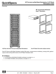
A complete WebAccess system consists of three basic areas, illustrated below.
Figure 1.6 WebAccess Network Components
•
Client (Web Browser VIEW of real-time Data) and an Active-X
control called the Plug-in
•
SCADA Node – a PC that communicates with automation
devices and the Clients.
•
Project Node - the Configuration Tool, Central Data base and
Web Server. .
•
Network Service – runs on the SCADA Node and Project node
and provides file transfer and real-time data transfer to Clients
and SCADA nodes (webvrpcs.exe is the name of the network
service that runs on SCADA nodes and Project Node).
•
Thin Clients - which display snapshots of graphics and use a
text based interface to change data, acknowledge alarms and
control. No software installation required. Supports PDA and
Pocket PCs
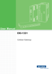
Stand-alone systems are implemented in one of two general ways:
Broadwin Technology, Inc.
Revsion A March 16, 2006
Ver 5.0
5
Basic Training • 1. Introduction
WebAccess HMI & SCADA software
•
The SCADA Node software and Project Node software are on the same PC.
•
The SCADA Node software is on the PC and the Project Node Software is on a
mobile laptop or remote PC.
Figure 1.7 Stand-alone SCADA Node
Standalone PC with remote dial up access
Figure 1.9 Single SCADA Node - remote access
Configuration (also called the Project Manager)
The configuration tools are:
•
Project Manager - This module allows you to configure tags mapped to device
addresses. Other functions, such as recipes, trending, networking and scripts, are
also configured in this module. This is on the Web Sever / Project Node.
•
Graphic Builder - This module is used to create graphics for run-time display. Tags
configured in the database can be associated with graphical elements to enable
animated display of process data. DRAW is the web browser version that runs on a
Client web-browser when connected to Project Node. DrawDAQ runs locally on the
Project Node (without a web browser).
Broadwin Technology, Inc.
Revsion A March 16, 2006
Ver 5.0
6
Basic Training • 1. Introduction
WebAccess HMI & SCADA software
Client
The Client consists of a Web-browser and the Client Plug-in. SCADA Nodes also have a
non-web browser version of the Client called ViewDAQ.
Client Plug-in
The Client Plug-in is used by Web Browsers to VIEW real-time data and DRAW. It
consists of two parts: 1) an Active-X control for Internet Explorer (an OCX) and 2) a
Netscape Navigator Plug-in.
Internet Explorer 6.0 is recommended and supports all features of WebAccess (including
Video).
Note – future support for Netscape is not guaranteed because of the ill-defined future
AOL-Time Warner and Mozilla have announced for Netscape Navigator.
There are two functions performed by the Client Plug-in:
•
VIEW - These are the real-time displays that form the operator interface. They
include graphical displays with full motion animation, pre-built graphics, such as the
Alarm Summary, Data Log Trends and Point Detail display and Video Multiple Clients
can be running at the same time on the same PC or other PCs.
•
DRAW –Graphics displays can be built using an ordinary web browser. The Client
Plug-in allows engineers and technicians to build and animate graphic displays.
OEMs, system integrators and engineers can modify and support systems remotely
over the Internet or an intranet.
SCADA Node
The SCADA node runs independently of any node in the system.
•
Kernel (datacore.exe)- This consists of a real-time kernel that handles all the
communications with the external automation devices and Clients. It is also
responsible for logging historical data, alarm functions, executing event programs,
printing reports, etc.
•
Device Driver(s) - This handles the communication protocol between WebAccess and
the external device.
•
Web Service (webvrpcs.exe) – this provides the remote communication over the
Internet or intranet. This is the icon that appears in the taskbar next to the clock
•
ViewDAQ – this is a non-web browser version of VIEW. It runs on the SCADA node
locally. It is used for stand-alone systems and control room applications. It also
provides a type of redundancy allowing operators to view and control even if the
network connection is down.
Project Node
The Project Node is a central database and the Web Server. The Project Node holds a
copy of the database and graphics of all SCADA Nodes in the system. A user downloads
these files from the Project Node to the SCADA node via a web browser.
•
Project Manager - The Project Manager is the configuration tool. It consists of a
collection ASP pages and databases to allow an ordinary web browser to configure
Broadwin Technology, Inc.
Revsion A March 16, 2006
Ver 5.0
7
Basic Training • 1. Introduction
WebAccess HMI & SCADA software
tags, alarms, reports, scheduled and perform all the engineering using fill-in-theblanks configuration. The Project Node provides a number of utilities for project
deployment and maintenance including EXCEL Import, EXCEL Export, the OPC
Import tool and Import SCADA Node to import tags and graphics from another
project or PC:
•
DrawDAQ – this is a non-web browser version of DRAW. It runs on the Project node
locally (or a combined Project Node / SCADA Node). It is used for stand-alone
systems and control room applications. It allows engineers and technicians to build
and animate graphic displays.
•
OPCTool - These enable you to and import tags from an OPC Client into a WebAccess
tag database from a third party application OPC Servers, such as Cimetrics Bacnet
OPC Server, Kepware OPC Servers. Many automation hardware suppliers supply
OPC Servers as the communications interface to their proprietary networks.
Basic Terminology
Tag
A tag can consist of a single I/O point, multiple I/O points, or an internal point. I/O tags
are read and written to PLCs, controllers, DCS, DDC and IO hardware over a network
(either serial or LAN). Internal Tags include Calculation Tags, Accumulation Tags (e.g.
Totalizers), Constants and System information Tags and animation tags.
The term Tag comes from Industrial Plants, where each instrument had a metal or
plastic Tag describing it, and from computer databases, where a tag is row of
information in the WebAccess database that has a real-time value during run-time
operation and other values, such as Engineering Units, Alarm Limits, and Description.
Block
A Block is a single Tag Name that has more than one real-time value associated with it.
A PID controller or a VAV controller is an example of Blocks that consist of
Measurement, Setpoint, Output, Auto/Manual Status and Tuning Parameters. A Block
consists of multiple I/O points.
Parameter
A Block consists of Multiple Parameters. Each real-time IO value is a separate
parameter. For example, the Measurement is one Parameter of a PID Block, the Setpoint
is a second parameter, the Output is a third parameter, etc.
WebAccess also uses parameters as a template to guide novice users to create ordinary
tags. For example, the Modbus Driver comes with parameters for Analog Inputs, Analog
Outputs, Digital Inputs and Digital Outputs with preconfigured address, scaling and
conversion information. A parameter can guide a novice user in creating
communications to a device by modifying the parameters unique to each WebAccess
device driver.
Parameters can also be used in large projects as a productivity tool to create
“standards” for typical flow measurements, level measurements, pressure
measurements, etc
Broadwin Technology, Inc.
Revsion A March 16, 2006
Ver 5.0
8
Basic Training • 1. Introduction
WebAccess HMI & SCADA software
Graph
“Graph” is an abbreviation for Graphic Display.
Broadwin WebAccess Documentation
WebAccess documentation is supplied with a set of technical manuals, as:
o
Web Help, on every Project Node viewable from any web browser.
o
HTML Help, on every SCADA node
o
on paper (a little out of date)
o
or CD-ROM and in the WebAccess Node setup from the ftp site.
Document
Information Provided
Installation Manual
Installing the software and updating from a
previous version of WebAccess
Quick Start Guide
Tutorial to guide you through the first steps in
using WebAccess
Engineering Manual
Reference information on configuring a project and
utilities
Operator Manual
Reference information on run-time operation
Device Driver Guides
Device-specific information, such as
communication requirements, wiring, address
format and pre-built parameters and blocks.
Additional technical information in the form of Application Notes, Frequently Asked
Questions (FAQ), and white papers are available from the Broadwin Technology Inc.
Web Site at:
http://www.broadwin.com
http://broadwin.com/Literature/ ,
http://broadwin.com/Literature/#HelpFiles ,
http://broadwin.com/Literature/#UserGuides ,
http://broadwin.com/Manual/InstallGuide/InstallGuide.htm ,
http://localhost/broadWeb/EngMAN/EngMAN.htm ,
http://demo.broadwin.com/Manual/OpMan/OpMan.htm ,
http://broadwin.com/Manual/QuickStart/quickstart.htm
http://broadwin.com/broadweb/EngMan.EngMan.htm
Broadwin Technology, Inc.
Revsion A March 16, 2006
Ver 5.0
9
Basic Training • 1. Introduction
WebAccess HMI & SCADA software
Figure 1.10 - Help opens the Operator Manual in VIEW
Figure 1.11 – Engineering Manual opens from HELP in Project Manager
Broadwin Technology, Inc.
Revsion A March 16, 2006
Ver 5.0
10
Basic Training • 1. Introduction
WebAccess HMI & SCADA software
Exercises
This goal of this exercise is to become acquainted with WebAccess VIEW. This shows
what an ordinary user will encounter when first connecting to an established WebAccess
system via a web browser.
Note – the address of the Demo Project maybe different than listed below. Use the IP
Address the instructor gives you to connect for this exercise.
What you need to complete this exercise:
a. Windows 98, 2000, XP, 2003, or Vista.
b. Internet Explorer 6.0 or 7.0
c. Network connection to http://demo.broadwin.com or http://67.94.27.175
or to http://localhost or to a WebAccess Project Node in the classroom
via a hub or switch or Project Node installed on your PC.
Task 1: Connect to WebAccess Demo Project with a web browser.
1.
Start Internet Explorer.
•
Double Click the Icon on your Desktop
•
OR, Click Icon on your Taskbar
•
OR, From the Start button select:
Start->Programs->Internet Explorer
2. Enter IP Address, network address, computer name, host name or URL of
the WebAccess Project in Web Browser.
Enter the IP address or URL into the "Address Bar" (see figure 1.1) given by your
instructor.
For the Live Demo enter http://demo.broadwin.com/
Broadwin Technology, Inc.
Revsion A March 16, 2006
Ver 5.0
11
Basic Training • 1. Introduction
WebAccess HMI & SCADA software
Figure 1.13 - Internet Explorer Web Browser - Address Bar
About Addresses
The first time you connect, you must enter the address of your WebAccess Project in the
Address bar of your Web Browser. Later, you can add this address to your "Favorites". The
address can take several forms:
URL is the Universal Resource Locator, for example http://www.broadwin.com/. If
•
your company has assigned a URL to your WebAccess Project, enter this in the Address
Bar of Internet Explorer. URL also can have similar forms, for example the WebAccess
Live Demo project node can be reached at http://demo.broadwin.com/
•
IP Address, Internet Protocol Address. The IP address is a series of four numbers
separated by periods (e.g. http://67.94.27.175/ is the IP Address of
demo.broadwin.com).
Computer Name - If you are on an Intranet, you can enter the computer name of
•
the WebAccess Project Node (for example "Server1"). This can be either a TCP/IP "host
name" or the Microsoft Network name.
Host name – This is like a computer name, but uses a name installed in the HOSTS
•
file of the Client PC. The HOSTS file redefines the IP address and allows different users
to use different IP Addresses to access the same SCADA and Project Nodes. This might
be required if some users on an Intranet (using private IP address) and others are on
the Internet (using Public IP Address) and the router or firewall does allow private users
to use the Public IP address to connect to the SCADA node. The localhost name is an
example of a HOST name. For example. “localhost” is the default host name for the local
PC address. It is mapped to 127.0.0.1
Hint – The hyperlinks later in this Training Guide connect to “localhost”. If you do not have IIS web server
installed on your PC, you can modify the HOST file to redirect “localhost” to a PC on your network
that does have IIS web server software and the Engineering Manual Installed (e.g. Project Node
software installed). See the Appendix for a “How to”.
•
Local PC - If you are on a PC that has the Project Node software installed and a
network card, you can use the default localhost address or url:
http://localhost
Broadwin Technology, Inc.
Revsion A March 16, 2006
Ver 5.0
12
Basic Training • 1. Introduction
WebAccess HMI & SCADA software
or
http://127.0.0.1
No Network - If you are on a standalone PC without a network
•
card, you must use the computer name: (for example
"http://mycomputername").
3. Press the Enter key or Select Go.
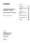
4. WebAccess Home Page Opens (figure 1.14)
Congratulations! You have successfully connected to a WebAccess
Project. It took no special software to connect. No software download was
required.
There are two choices on the WebAccess Home Page (bwroot.asp).
•
WebAccess Configuration
•
WebAccess View
Note – so far you have used only TCP Port 80 that most all firewalls
allow.
Figure 1.14 - WebAccess default HOME - Welcome Page
Task 2: Download and Install Client Plug-in.
1. Select the WebAccess View button (Figure 1.14).
Broadwin Technology, Inc.
Revsion A March 16, 2006
Ver 5.0
13
Basic Training • 1. Introduction
WebAccess HMI & SCADA software
This is to view the run-time version of WebAccess HMI & SCADA that ordinary users will
see.
Note -
WebAccess Configuration is for engineers and integrators and will be explored over the next 3 days.
2. Download and Install Client Plug-in
WebAccess uses an ActiveX control to display animated Graphics. The first time you
connect to WebAccess, you will need to download and install the client plug-in.
If you have not already installed the Client, you will see a message:
"Please Click here to install WebAccess Client first".
The first time you try to connect to VIEW or DRAW, you will be prompted to
download and install the Client Plug-in.
Figure 1.15 - Prompt to download and install WebAccess Client
If you get this message, just follow the steps to download and install the client.
Hint -
If you need more information about downloading and installing the client plug-in, please refer to
Appendix in the Engineering Manual section for a step-by- step instructions on How to download
and install the client plug-in.
The Hyperlinks in this note are to the Engineering Manual and do not work until Section 2, Task
1: Install Project and SCADA Node Software is complete. The above Hyperlinks assume that the
Web Based Engineering Manual is installed on this Local PC. IIS is required for these links to
http://localhost/broadWeb/engman/EngMan.htm to work.
3. Windows File Download Dialog Box appears (Figure 1.16).
Broadwin Technology, Inc.
Revsion A March 16, 2006
Ver 5.0
14
Basic Training • 1. Introduction
WebAccess HMI & SCADA software
Figure 1.16 - Windows File Download dialog box
4.
Select Save (Figure 1.16) to save Setup.exe to disk. (Desktop).
The Client Plug-in is about 4 megabytes and contains the ActiveX control for Internet
Explorer (and a Navigator Plug-in). The setup file that you download is a selfextracting setup program named WebAccessClientSetup.exe. This is also available
on the WebAccess CD-ROM for users with slow network connections.
We recommend that you save to Disk unless you have a very fast Internet Connection.
We also recommend that you save to Desktop, so that you can find the Setup.exe
program easily in order to run Install.
5. The Windows Save As Dialog Box appears (Figure 1.17)
Figure 1.17 - Windows 2000 Save As Dialog Box
6.
Select the Desktop’s location to Save the Setup file.
7.
Select Save button (Figure 1.17).
8.
Download Dialog Box Appears (Figure 1.18)
Broadwin Technology, Inc.
Revsion A March 16, 2006
Ver 5.0
15
Basic Training • 1. Introduction
WebAccess HMI & SCADA software
Figure 1.18 - Download Complete
How long it takes to download the Client Plug-in depends on your Internet
connection. The file is approximately 4.9 Megabytes
9.
Select the Close button to close the Download Dialog Box, if it
did not close automatically (Figure 1.18).
Task 3: Start WebAccess VIEW in a web browser.
1. Re-Start Internet Explorer. (Repeat Task 1 above)
2.
Enter IP Address, network address, computer name, host name or URL of the
WebAccess Project in Web Browser. (Repeat Task 1, step 2 above).
3.
Select the WebAccess View button (Figure 1.14).
4. The WebAccess View Login Page appears (Figure 1.19).
Figure 1.19 VIEW Login
4a. If there are more than one Project or SCADA node, a Project Tree appears (Figure
1.20).
Select Start View under the SCADA node from the
Navigation Tree in the left frame.
Broadwin Technology, Inc.
Revsion A March 16, 2006
Ver 5.0
16
Basic Training • 1. Introduction
WebAccess HMI & SCADA software
Figure 1.20 VIEW Login - multiple Nodes
Hint -
Notice that Figure 1.19 does not show the Navigation Tree in the left frame. Yet, Figure 1.20 shows
multiple Nodes each with Start Node, Start View and Stop Node. If there is only one SCADA Node in
the project, the navigation tree is not shown.
5. Click on "Please Login" (Figure 1.19 or 1.20).
6. The Login Dialog Box appears (Figure 1.21).
Figure 1.21 - Login Dialog Box
7. Enter your "User Name" assigned by the engineer or technician who configured the
system. Note that you can use either your keyboard or the mouse in the Login
dialog box.
8. Enter your "Password".
4. The Demo login and the Default login is,
5. User Name: admin
6. Password:
(i.e. a blank password)
Tip - if this is a newly installed system, use the default login username: admin with a
blank password/
Broadwin Technology, Inc.
Revsion A March 16, 2006
Ver 5.0
17
Basic Training • 1. Introduction
WebAccess HMI & SCADA software
5.
Press the Enter key.
6. The MAIN graphic display for your system appears. The default MAIN graphic
supplied with WebAccess is shown below (Figure 1.22). Yours will probably look different
Figure 1.22 - default Main graphic display
The MAIN graphic display appears with navigation frame on the left if there are multiple
SCADA Nodes or multiple Projects.
Figure 1.23- default Main graphic - multiple Nodes
Broadwin Technology, Inc.
Revsion A March 16, 2006
Ver 5.0
18
Basic Training • 1. Introduction
WebAccess HMI & SCADA software
Main Graphic is a user built display and yours may look different. The Main Graphic in
the WebAccess Live Demo (http://demo.broadwin.com) or (http://67.94.27.175) is
shown below.
Figure 1.24 - Main Graphic WebAccess Live Demo - Power User Login.
Congratulations! You are connected via the Internet to the first fully web-base HMI and
SCADA system.
Other Ways to Start VIEW:
a. A link on an HTML web page
This might be your corporate Web Page, created by your system
administrator or web master. It will probably use the bwviewpg.asp with
options that include automatic log in.
The Broadwin Technology web site has a link like this.
http://demo.broadwin.com/broadWeb/system/bwviewpg.asp?proj=LIVEDEMO&node
=SCADANode1&user=tom&pass=tom&tree=0&goto=graph=1welcome.bgr&tool=1&c
apt=1&stat=1
The short hyperlink is Click Here!
If you remove the user and pass options, then you will be prompted to
login.
b. Favorites menu
You can create a link yourself by using the Add to Favorites feature in
Internet Explorer. (Netscape users call this a Bookmark). You can use the
Add to Favorites in Internet Explorer the first login described in Start
View.
Broadwin Technology, Inc.
Revsion A March 16, 2006
Ver 5.0
19
Basic Training • 1. Introduction
WebAccess HMI & SCADA software
Favorites -> Add to Favorites
c. One Click Log-ins
Users can login directly to View without having to enter a password, if you
create hyperlink in an HTML page, email or an ASP page with the user
login, password and project information using the bwviewpg.asp with
options. The Live Demo has several "One Click" logins that are
hyperlinks:
Power User LOG IN (click here!) This link works only if
connected to the Internet.
Restricted User LOG IN (click here!) This link works only if
connected to the Internet.
You could email these (or your own) hyperlinks with all the information to
log-on, then ask the user to connect using the hyperlink and then Add to
Favorites. This would allow the user to login with one click on his
favorites folder. Favorites -> Add to Favorites
Go to exercise 4 for step-by-step tour of display navigation.
Task 4: WebAccess Display Navigation
1. Start Internet Explorer.
2. Login to WebAccess VIEW.
3. Right Click the mouse inside the WebAccess Browser window.
4. Navigation Popup Menu appears (Figure 11.25).
Figure 1.25 - Right Click VIEW Menu
5. Drag the mouse down the Navigation Popup Menu to GOTO (Figure 11.26).
Broadwin Technology, Inc.
Revsion A March 16, 2006
Ver 5.0
20
Basic Training • 1. Introduction
WebAccess HMI & SCADA software
Figure 1.26- Navigation Popup Menu - GOTO menu selected
On any display, you can Right Click the Mouse the get a Navigation Popup Menu.
6. Select Alarm Summary to view current Alarms.
7. Right Click -> Goto -> Graph opens the Graph List Dialog Box.
The Graph List Dialog Box pops open (Figure 1.27).
Figure 1.27- Graph List Dialog Box - in VIEW
8. Double click on the Graphic name in the Graph List Dialog Box.
For example, double click on Meter.bgr
Broadwin Technology, Inc.
Revsion A March 16, 2006
Ver 5.0
21
Basic Training • 1. Introduction
WebAccess HMI & SCADA software
OR
Single click on the Graphic name and press OK.
9. The graphic display you selected appears. (Figure 1.28 shows an example from the
LiveDemo of the Meter display).
Figure 1.28 user-built Graphic Display from Demo (named Meter.bgr).
Only user-built Graphic Displays with the *.bgr extension are listed in the Graphic List
("Graph List). Note that the word "Graphic" is abbreviated "Graph" in most menus and
dialog boxes.
Broadwin Technology, Inc.
Revsion A March 16, 2006
Ver 5.0
22
WebAccess HMI & SCADA software
Basic Training • 1. Introduction
Toolbar
Figure 1.29 - standard Toolbar for graphic display
The Toolbar is a row of pushbuttons at the top of each graphic display window. The
toolbar is used to call new displays, acknowledge alarms and open dialog boxes.
Engineers can customize the appearance of the toolbar, by adding or deleting buttons
and icons. The toolbar can change based on the display being viewed. Users can hide
the toolbar using View Property link. Engineers can hide the toolbar by using the
bwviewpg.asp options.
The Status Bar at the bottom of the display shows the description of each button on the
Toolbar by moving the cursor over that button.
Figure 1.30 - Toolbar functions described by Status Bar
The Right Click Menu (in a web browser VIEW) is also another easy way to navigate.
ViewDAQ users (i.e. the non-web browser version local to SCADA Node) have a menu
bar. Keyboard Function Keys provide an alternative to the Toolbar and Menus.
Standard Toolbar buttons
Figure 1.31 Standard Toolbar buttons
The buttons on the standard Toolbar for a graphic display are (listed left to right):
NOTE – The Hyperlinks on this page to the Operator and Engineering Manuals at demo.broadwin.com. See the
Appendix for details.
Broadwin Technology, Inc.
Ver. 5.0
23
Revision A March 16, 2006
Basic Training • 1. Introduction
WebAccess HMI & SCADA software
Overview
Groups
Opens first Overview Group Display. (Does
nothing if no Faceplate Groups are configured).
Faceplate
Groups
Opens a Dialog Box listing the Faceplate
Groups. (Does nothing if no Faceplate Groups are
configured).
Real Time Trend Opens a Dialog Box listing the "Real
List
Time Only Trend" displays. (Does nothing if no
RealTime Trend Groups are configured).
Data Log Trend Opens a Dialog Box listing the "Real
List
time and Historical Trend" displays. (Does
nothing if no Datalog Trend Groups are configured).
Alarm
Summary
Opens the Alarm Summary of current alarms
Alarm Group
Opens a Dialog Box listing the Alarm Group
displays.
Recipe
Opens a Dialog Box listing the Recipe files,
Recipes and processing Units. (Does nothing if
no Recipes are configured).
Graphic List
Opens a Dialog Box listing user
built graphic displays.
Video
Opens a Dialog Box listing the Video cameras
configured for the system. (Does nothing if no
cameras are configured).
Acknowledge
Screen
Acknowledges all alarms displayed on this
graphic display.
Acknowledge
Point
Acknowledges the selected Tag or Block
Parameter.
Change
Opens the Change Dialog box for the selected
tag.
Point Info
Opens the "tag browser" dialog box listing all
tags in the system (based on user
login). Restricted Users will only see tags from their
assigned displays. General and Power Users will see
all tags.
Back
Back to previous graphic display.
Forward
Move forward in display history queue.
Global Script
Opens the global script monitor display (Power
Users and Admin only using VIEW in a web
browser).
Station Status
Opens the communication status display
(Power Users and Admin only using VIEW in a web
browser).
Alarm Log
Opens a record of the last 10,000 alarms on
this SCADA Node (Power Users and Admin only
using VIEW in a web browser). For a similar list,
NOTE – The Hyperlinks on this page to the Operator and Engineering Manuals at demo.broadwin.com. See the
Appendix for details.
Broadwin Technology, Inc.
Ver. 5.0
24
Revision A March 16, 2006
WebAccess HMI & SCADA software
Basic Training • 1. Introduction
see the Alarm Log from Central Database Logs.
Action Log
Opens a record of the last 10,000 operator
actions. (Power Users and Admin only using VIEW
in a web browser). For a similar list, see the
Alarm Log from Central Database Logs.
User Program
Opens the status display of any 3rd Party
programs started and monitored by WebAccess
(Power Users and Admin only using VIEW in a web
browser).
Toolbar, GOTO Menu and Keyboard have similar functions
The "GOTO Menu" (Figure 1.26), the "Toolbar" (Figure 1.29) and the Function keys on your
keyboard all perform the same function.
For example, selecting "Alarm Summary" in the "GOTO Dialog Box", clicking on F5 on the
default toolbar or pressing the F5 key on your keyboard all do the same thing, they call up the
Alarm Summary display. The default toolbar is usually replaced with buttons using icons,
symbols or text. Yours might look different. For example, the F5 button on the toolbar is
usually replaced with the words "ALARM SUMMARY".
See Keyboard Function Keys, for a description of all the Display Navigation available using the
Keyboard Function Keys.
Keyboard Function Keys
These commands are the same as pressing the Function keys on the Keyboard of the PC
(F1 through F10) and the Ctrl and the Shift keys.
Keyboard
Description
Equivalent Keymacro
F1
Overview Display
<GOTO>OVERVIEW=1
F2
Faceplate Group List
<DIALOG>FPLGROUP
F3
Real Time Trend List
<DIALOG>REALTRD
F4
Data Log Trend List
<DIALOG>DLOGTRD
F5
Alarm Summary
<GOTO>ALMSUMMARY
F6
Alarm Group List
<DIALOG>ALMGROUP
F7
Block Detail Display
<GOTO>BLOCKDTL=@%TPICKTAG
F8
Recipe List
<DIALOG>RECIPE
F9
Graphic List
<DIALOG>GRAPH
F10
Video List
<DIALOG>VIDEO
Shift + F1
Download Recipe
(Recipe Display Only)
NOTE – The Hyperlinks on this page to the Operator and Engineering Manuals at demo.broadwin.com. See the
Appendix for details.
Broadwin Technology, Inc.
Ver. 5.0
25
Revision A March 16, 2006
Basic Training • 1. Introduction
WebAccess HMI & SCADA software
Keyboard
Description
Equivalent Keymacro
Shift + F3
Scale Recipe
(Recipe Display Only)
Shift + F7
Point Detail Display
<GOTO>POINTDTL=@%TPICKTAG
Ctrl + F1
Acknowledge Screen
<ALMACK>
Ctrl + F2
Acknowledge Point
<ALMACKS>@%TPICKTAG 0 0
Ctrl + F3
Change Point
<DIALOG>TAGVALCHG=@%TPICKTAG
Ctrl + F5
Point Info List
<DIALOG>POINTINFO
Ctrl + F6
Global Script Status
<GOTO>GSCRIPT
Ctrl + F7
Station Status
<GOTO>STATION
Ctrl + F8
Alarm Log
<GOTO>ALARMLOG
Ctrl + F9
Action Log
<GOTO>ACTIONLOG
Ctrl + F10
User Programs
<GOTO>USRPRG
Alt + F4
Close Display Group Windows.
Keyboard will close Web Browser.
<CLOSEDSP>@%TDAQDSPNAME
Page Down
Calls Down Link Graphic
Page Up
Calls Up Link Graphic
Esc
Calls Main graphic Display
<GOTO>Graph=Main.bgr
NOTE – The Hyperlinks on this page to the Operator and Engineering Manuals at demo.broadwin.com. See the
Appendix for details.
Broadwin Technology, Inc.
Ver. 5.0
26
Revision A March 16, 2006
WebAccess HMI & SCADA software
Basic Training • 1. Introduction
Task 5: Browse Tags with the Point Info Dialog Box
1. Right Click -> Goto -> Point Info opens the Point Info Dialog Box (the Tag
Browser of all tags in the system).
Figure 1.20 - Point Info Dialog Box
2. Select a point or Tag from the list on the left of the dialog box. (For example, pick
AC12_OAT in Figure 1.20). You can also type the tag name using the keyboard.
The Point Info Dialog Box shows the current Value, Description, Point Type, High and
Low Span and Engineering Units.
The Point Info Dialog Box is a menu of all Points (IO Tags, Blocks and system Tags) plus
information about them, including current value, alarms, Displays they appear. The Point
Info Dialog box also has the ability to change the value of tags based on user security
and will open a login dialog box if user security is too low. The tags listed are based on
user login. Restricted Users will only see tags from their assigned displays. General and
Power Users will see all tags.
Value: Flashing Red means the tag is in Alarm and is Unacknowledged. Steady Red
means the tag is in Alarm and is Acknowledged. Asterisks (*) or a number in brackets
means a communications failure. Blue is Normal.
The Acknowledge button
will acknowledge the highest alarm associated
with the tag (the tag should stop flashing). If there are multiple alarms, then the
acknowledge button must be pressed multiple times. The Alarm Summary describes the
alarm type associate with tag. Restricted Users can be prevented from acknowledging
alarms, depending on the security assigned to them.
NOTE – The Hyperlinks on this page to the Operator and Engineering Manuals at demo.broadwin.com. See the
Appendix for details.
Broadwin Technology, Inc.
Ver. 5.0
27
Revision A March 16, 2006
WebAccess HMI & SCADA software
Basic Training • 1. Introduction
Tag Name
The Tag name (or Block and Parameter Name) is how WebAccess identifies this
information on displays, logs, alarms, trends and reports. A typical tagname is FIC101 or
AC3_OAT.
Description
Description: is the user assigned description for this tag used in displays and alarms. A
typical description is Boiler #1 Feedwater Flow. The description is 25 alphanumeric
characters.
Tag Type
Tag Type: is the Data Type of the tag or parameter. The types are Analog, Digital or
Text.
Analog is a floating Point Number (e.g. 0, 101.234, 100, -999.1).
Discrete is a state between 0 and 7, usually with a Descriptor (e.g. RUN, STOP,
ON, OFF). Digital is also called Discrete.
Text is ASCII data consisting of letters and numbers.
Scan Type
Scan Type defines the type of scanning performed by the Tag or Block Parameter.
Constant Scan means the Tag is always scanned as long as the SCADA node is
running. Constant scanning must be used for all I/O points that require
continuous update (alarming, trends, logs, batch, scripts, logic).
Display Scan is for infrequently accessed tags, like tuning parameters and
setpoints. Display Scanning occurs only when a Display is being viewed with this
tag on it. Display Scan is a means of optimizing or increasing communications
throughput.
Some drivers provide other Scan options. Scan Type is chosen from a pull down
menu showing valid scan types for this device.
Port
This is also called the Com Port. This is the communications port the tag is using to
read or write data from automation devices including PLCs, Controllers and IO. The
STATION STATUS Display can be used to view the status of the comport. The %DAQ
System Tag can also be used to monitor the Status of the comport using
%DCOMST(tagname.COM). Comport numbers less than 1 represent Internal Tags
(Accumulation, Constant, Calculation, System and Screen Tags). For IO Tags and Blocks,
the COM Port is the physical comport configured in WebAccess Configuration Manager.
For Network and Software Interfaces (like DDE, OPC and API), the COM port may be a
virtual number. For Serial and some API interfaces, the comport is the physical
communications port (i.e. COM1, COM2, COM3, etc.).
NOTE – The Hyperlinks on this page to the Operator and Engineering Manuals at demo.broadwin.com. See the
Appendix for details.
Broadwin Technology, Inc.
Ver. 5.0
28
Revision A March 16, 2006
Basic Training • 1. Introduction
WebAccess HMI & SCADA software
-1 = Accumulation Tag (Internal Tag)
-2 = Calculation Tag (Internal Tag)
-3 = Constant Tag (Internal Tag)
0 = Local Screen Tag or %DAQ System Tag (Internal Tag)
1 to 255 = Physical Comport (Com1, Com2, etc) or Virtual Port
Range: -3 to 255
You can select the comport using the
keys to see up to port 12.
keys. Use the Up / Down arrow
Unit
The Unit Number describes the field device (e.g. PLC, RTU, Controller) this tag reads.
Depending on the driver, this may be the physical address of the device. Technicians
and engineers configure unit Number when they create the device in WebAccess Project
Manager.
Device Name
Device Name is a description of the Automation device the tag connects in order read or
write data. Automation devices include PLCs, Controllers and IO. Typical Device Names
are PLC1, CTL202, and VAV300. Engineers and technicians assign the Device Name
when they create the Device in the WebAccess Project Manager.
Address
Address of data in the field device to be read or written by this tag. Address is initially
set when the Tag or Block was built. Address is very device dependent. Refer to the
device driver manual for more details.
The Goto button
trends the tag is used on.
opens the Goto Point Info list of all the displays and
will open the Change Dialog box allowing an operator
The Change button
to change the value of the tag (with the appropriate security).
NOTE – The Hyperlinks on this page to the Operator and Engineering Manuals at demo.broadwin.com. See the
Appendix for details.
Broadwin Technology, Inc.
Ver. 5.0
29
Revision A March 16, 2006
WebAccess HMI & SCADA software
Basic Training • 1. Introduction
Figure 1.21 - Change dialog Box for ANALOG tag
"Analog" is any floating-point number (-99999999999 to 999999999999). The
maximum size of an Analog Tag is 12 digits including sign and decimal point. You
can use the keyboard, mouse, or touch-screen to enter values. The Keyboard keys
are: F1 to Hold Output, ENTER, TAB select Exit.
Figure 1.22 - Change Dialog Box for a DISCRETE Tag
Figure 1.23 Change Dialog Box for TEXT-type tag.
NOTE – The Hyperlinks on this page to the Operator and Engineering Manuals at demo.broadwin.com. See the
Appendix for details.
Broadwin Technology, Inc.
Ver. 5.0
30
Revision A March 16, 2006
WebAccess HMI & SCADA software
Basic Training • 1. Introduction
Task 6: Use the Change Dialog Boxes
1. Open the Change Dialog Box, there are at least three methods:
a.
Select an Analog Tagname from the Point Info Dialog Box the pick the Change
button (Figure 1.21).
OR
b. Double click on any pick-able dynamic number on a user built graphic (Figure
1.16).
OR
c. Pick a Tag and use the Ctrl-F3 key or the
1.19).
2.
on the Standard Toolbar (Figure
The Analog Change Dialog Box appears (Figure 1.24).
Figure 1.24 - CHANGE dialog Box for ANALOG tag
3. Click Hold Output to keep the dialog box open while making a change instantly
effective (Figure 1.24).
4.
Click the Ramp Arrows to change a value
(Figure 1.24).
a. OR, Click the number keys in the Change Dialog Box
(Figure 1.24) to enter a value.
b. The UP and Down (↓) keys on the keyboard can also be used to ramp the value
of an Analog tag in the Change Dialog Box.
5.
Click Enter to close the Change Dialog Box (Figure 1.24)
NOTE – The Hyperlinks on this page to the Operator and Engineering Manuals at demo.broadwin.com. See the
Appendix for details.
Broadwin Technology, Inc.
Ver. 5.0
31
Revision A March 16, 2006
WebAccess HMI & SCADA software
Basic Training • 1. Introduction
6. Click Exit to close the Point Info Dialog Box (Figure 1.24)
making a change. (If Hold Output is depressed).
without
Hold Output
If the Hold Output button is depressed (i.e. enabled)
made until the enter key is pressed.
, then changes are not
If the Hold Output button is depressed (i.e. enabled), then Exit will cancel any
keystrokes and no change will be made.
If the Hold Output button is raised (i.e. disabled)
State button is immediate.
, then any change to a
The F1 key on the keyboard will toggle Hold Output.
Dec
Dec displays the number read from the Field IO device as Decimal Number (i.e. base
10, 0 to 9).
Hex
Hex displays the number read from the Field IO device as a Hexadecimal Number (i.e.
base 16, 0 to F where F16 = 1510 ).
Bin
Bin displays the number read from the Field IO device as a Binary Number (i.e. base 2,
0 to 1 where 102 = 210 ).
Oct
Oct displays the number read from the Field IO device as an Octal Number (i.e. base 8,
0 to 7 where 108 = 810 ).
Change Dialog Box - Discrete Tags
"Discrete" is any integer number (from 0 to 7). That's 3-bits of data.
The most common discrete tag is a Digital Tag (On/Off, True/False) that is 1-bit of data.
NOTE – The Hyperlinks on this page to the Operator and Engineering Manuals at demo.broadwin.com. See the
Appendix for details.
Broadwin Technology, Inc.
Ver. 5.0
32
Revision A March 16, 2006
WebAccess HMI & SCADA software
Basic Training • 1. Introduction
Figure 1.25 - Change Dialog Box for 2-state Discrete Tag (i.e. Digital)
An example of 2-bit discrete is the On-Off, and Transition State of a Block Valve
(0=open and should be open, 1=open, but should be closed, 2=closed but should be
open and 3=closed and should to be closed).
WebAccess will automatically resize the Discrete Dialog Box to bit the number of 'bits"
read by the tag from the IO device. (3-bits max bit length).
Figure 1.26 - Change Dialog Box for 8-state (7-bit) Discrete Tag
Keyboard Keys for Change Dialog Box
You can use the keyboard, mouse or touch-screen to enter values. The keyboard keys
are:
•
F1 key to toggle Hold Output
•
Up Arrow and Down Arrow keys to change
The UP and Down (↓) keys on the keyboard can also be used to:
•
Select the State of a Discrete
•
Ramp the value of an Analog.
•
TAB will toggle between Enter and Exit buttons.
•
Enter will execute based on the selected Enter or Exit button.
This is useful for membrane panels or if the mouse or touch screen fails.
NOTE – The Hyperlinks on this page to the Operator and Engineering Manuals at demo.broadwin.com. See the
Appendix for details.
Broadwin Technology, Inc.
Ver. 5.0
33
Revision A March 16, 2006
Basic Training • 1. Introduction
WebAccess HMI & SCADA software
Task 7: View the Thin Client
The THIN CLIENT is intended for use with Hand-held PCs running WINDOWS CE (for
example, the iPAQ).
Figure – iPAQ 3900
WebAccess will test for the operating system and will direct Windows CE clients to the
Thin Client interface path.
You can use any PC to connect to the THIN CLIENT by typing the full path to the Thin
Client Interface.
1.
Connect to the thin client by typing the address given by your instructor with
broadweb/hd1/m.asp appended to the ip address.
http://ipaddress/broadweb/hd1/m.asp
OR
For the Demo type:
http://demo.broadwin.com/broadweb/hd1/m.asp
or
http://67.94.27.175/broadweb/hd1/m.asp
You can use any PC to view the Thin Client. Pocket PCs using Windows CE are
automatically redirected to the thin client (i.e. Windows CE only needs to type IP
address without the additional path).
NOTE – The Hyperlinks on this page to the Operator and Engineering Manuals at demo.broadwin.com. See the
Appendix for details.
Broadwin Technology, Inc.
Ver. 5.0
34
Revision A March 16, 2006
WebAccess HMI & SCADA software
Basic Training • 1. Introduction
Figure 1.27 – THIN CLIENT
2. Select a SCADA Node by clicking on the yellow pointer
.
3. Log in to the Thin Client
Login: admin
Password:
blank
( i.e. no password)
Figure 1.28 – THIN CLIENT – Log in
NOTE – The Hyperlinks on this page to the Operator and Engineering Manuals at demo.broadwin.com. See the
Appendix for details.
Broadwin Technology, Inc.
Ver. 5.0
35
Revision A March 16, 2006
Basic Training • 1. Introduction
WebAccess HMI & SCADA software
Figure 1.29 – Thin Client Menu Display
4. Click the yellow pointers to expand
alarms etc.
and compress
the list of displays, tags,
5. Click on any Graphic to enlarge it.
Figure 1.30 – typical THIN CLIENT Graphic Display
with control tags (2ductAHU1.bgr).
6. Click on a Tag Name to change the Tag
NOTE – The Hyperlinks on this page to the Operator and Engineering Manuals at demo.broadwin.com. See the
Appendix for details.
Broadwin Technology, Inc.
Ver. 5.0
36
Revision A March 16, 2006
WebAccess HMI & SCADA software
Basic Training • 1. Introduction
Figure 1.31 – Change Tag in THIN CLIENT (FAN_START101)
NOTE – The Hyperlinks on this page to the Operator and Engineering Manuals at demo.broadwin.com. See the
Appendix for details.
Broadwin Technology, Inc.
Ver. 5.0
37
Revision A March 16, 2006
WebAccess HMI & SCADA software
Basic Training • 1. Introduction
Reference
The information in this introduction is also in the WebAccess Operators Manual.
The Operator Manual can be downloaded from the following locations:
http://demo.broadwin.com/broadweb/OpMan/OpMan.htm
http://broadwin.com/downloads/winhelp/OpMan.CHM
http://localhost/broadweb/OpMAn/OpMan.htm
The Operator Manual can be accessed from every WebAccess System using the
HELP hyperlink in WebAccess VIEW.
Figure - Help opens the Operator Manual in VIEW
NOTE – The Hyperlinks on this page to the Operator and Engineering Manuals at demo.broadwin.com. See the
Appendix for details.
Broadwin Technology, Inc.
Ver. 5.0
38
Revision A March 16, 2006
WebAccess HMI & SCADA software
Basic Training • 2. Node Software
Section 2 - Node Software
Installation
Objectives
•
Install Project Node and SCADA Node software
Training Notes
Hardware and Operating System
This section is intended as a quick list of things to consider. This section does not list
the detail here; instead, it is a reminder or checklist. Use this as a reminder and review
the appropriate section in the manual for details.
1. Hardware
Pentium III, Pentium IV, or Athelon processors are recommended for the Project Node
and SCADA nodes. The Clients should be Pentium or better.
A network card is needed for network applications.
Even for Standalone architecture nodes (Project and SCADA nodes combined, no
network), the TCP/IP service is needed. The loop back service can be installed for a
standalone system. Note that all configuration is through a Web Browser using IIS and
the TCP/IP protocol. A Stand-alone node can benefit from some sort of network access
to allow remote access and remote software administration. Windows provides a service
called RAS that allows remote dial-up over a modem. A network card and a cross-link
cable provide an easy method to copy data to or from a laptop
Data Logging Trend Files require a fast CPU and a Hard Drive with fast access times and
sufficient disk capacity. Data Logging requirements will also affect the number of SCADA
Nodes required. It is recommended to use a SCSI drive for data logging. It is further
NOTE – The Hyperlinks on this page to the Operator and Engineering Manuals at demo.broadwin.com. See the
Appendix for details.
Broadwin Technology, Inc.
Ver. 5.0
39
Revision A March 16, 2006
WebAccess HMI & SCADA software
Basic Training • 2. Node Software
recommended to use drive for data logging that is separate from your operating system
and WebAccess program drive.
5. File System
NTFS file system recommended for Project Node and SCADA nodes. NTFS provides
Security. FAT provides no security and is not appropriate for the Web Server
(Project Node) or SCADA node.
File compression is not recommended for the WebAccess DATALOG subdirectories,
since this will result in more overhead and slower performance.
6. Operating System
Project Node operating System: Windows 2000 or Windows XP Professional or
Server 2003 or Vista Business or Vista Enterprise with IIS. A Project Node
separate from the SCADA node increases the security of your SCADA node. Windows
Vista comes “locked-down” and requires you to take steps to enable IIS to work with
WebAccess (and ASP). See the Windows Vista section that follows.
SCADA Node: Windows 2000 or SERVER 2003 or Windows XP Professional or
Vista Business or Vista Enterprise. SCADA nodes do not need web server software.
If you have many SCADA Nodes using email alarms, emailed scheduled reports or MAIL
commands, you should install IIS with the SMTP (simple Mail Transfer Protocol).
Client: Windows 98, 2000 (Professional & Server), 2003 Server or XP (Home,
Professional and Sever) or Vista (Home, Business or Enterprise).
XP home and Vista Home will not work for Project Node (there is no Web Server
feature). XP Home is not supported for SCADA node.
XP Home, Windows 98, and ME do not support advanced graphic features. If your
clients are to use Win 98, ME or XP Home, limit the graphics they can view to basic
animation: vector rotation, color, motion. Bitmap rotation and Text rotation are not
supported by 98, ME or XP Home.
7. Web Server
IIS (Internet Information Service) is required for the Project Node. If email
notification of alarms and email of scheduled reports are to be used, then the SMTP
(Simple Mail Transfer Protocol) service must be installed and running on both the Project
Node and SCADA node. The Web Server (WWW Service) does not need to be installed
on the SCADA Node.
Windows Vista comes “locked-down” and requires you to take steps to enable IIS to
work with WebAccess (and ASP). See the Windows Vista section that follows.
SMTP Server (an option with IIS) is optional for Email Alarm Notification, emailed
scheduled reports or MAIL commands. The Simple Mail Transfer Protocol option allows
Project Node to forward email from SCADA Nodes to your corporate email server.
FTP Server is not recommended or needed. It is to much of a security risk.
8. Service Packs installed.
NOTE – The Hyperlinks on this page to the Operator and Engineering Manuals at demo.broadwin.com. See the
Appendix for details.
Broadwin Technology, Inc.
Ver. 5.0
40
Revision A March 16, 2006
WebAccess HMI & SCADA software
Basic Training • 2. Node Software
Service Pack 4 (SP4) is required for Windows 2000. SP2 Is required for Windows XP and
SP1 Is required for Server 2003. The latest service packs are recommended to improve
security of your project and SCADA nodes. REINSTALL SERVICE PACKS IF YOU ADD A
WINDOWS COMPONENT (e.g. you add IIS)!
9. Professional or Server (or Business or Enterpise)?
The Number of simultaneous connections to Project Node will affect your decision to use
2000 Professional or Server, XP Professional or Server 2003 or Vista Business or Vista
Enterprise for the project node. Professional is limited to 10 simultaneous connections.
Database Configuration, DRAW and the Thin Client require continuous connections to
project node (Web Server).
Connections to the SCADA node by Clients using VIEW are temporary and re-direct to
the SCADA node after an initial connection to the Project Node (Web Server). Clients
have a short-lived connection to the Project Node (Web Server) to get the address of the
SCADA node and to get few ASP pages. The connection from Client to Web Server is
then dropped until the Client either presses the refresh button (not done during normal
use of Web Access) or reconnects to SCADA node.
If you are using the Thin Client feature and have more than 10 users that will connect
simultaneously, you should consider using 2000 Server or Server 2003 or Vista
Business.
Scheduled Reports, HTML Reports of central ODBC Logs, and online changes to the
Scheduler from VIEW require a connection to the Project Node.
Many Operations in the Project Manager require multiple connections, for example every
time a comport is created a new connection is opened while the comport asp runs.
Vista Business appears to support over 4 million simultaneously (by it’s license). It
would seem that Vista Enterprise is not really needed for most WebAccess Applications
10. Internet Explorer 6.0 or 7.0
WebAccess uses ASP for its configuration (Project Manager) and the initial page (VIEW).
IE 6.0 or IE 7.0 must have ASP enabled.
Netscape and IE 5.0 can be used for evaluation purposes only. IE 5.0 appears to work,
but does not process java scripts correctly and can potentially corrupt your Database.
Never press the "submit" if using IE 5.0 to view configuration data. Netscape is slower
than IE 5 and although it appears to work, it is not recommended
11. Internet Explorer Security Settings
IE 6.0 and 7.0 security settings musts allow ActiveX control to run (Medium setting) this
can be accomplished in two ways:
Medium for Internet Zone - This affects all Internet sites visited and is less
secure than the adding Web Access as a Trusted Site.
NOTE – The Hyperlinks on this page to the Operator and Engineering Manuals at demo.broadwin.com. See the
Appendix for details.
Broadwin Technology, Inc.
Ver. 5.0
41
Revision A March 16, 2006
WebAccess HMI & SCADA software
Basic Training • 2. Node Software
Medium for Trusted Sites or Intranet- Instruct your users to add the
WebAccess Project node as a Trusted site. This allows a more restricted setting
for the Internet zone.
12.
Web Server Security
Anonymous Access is most common. But to increase security you should consider
Intergated Windows Authentication.
Integrated Windows Authentication for the Web Server is most secure. It will
require users to login with a password. It requires that users be "recognized" Windows
Users on the Project Node PC (local User) or the Domain of the project node (if a domain
is used). If users are all part of a domain used by the Project Node, the login will be
transparent for recognized users (i.e. no dialog box asking for password) much like
connecting to a shared drive or printer on your company's intranet.
13.
Network Addresses (IP or Computer Name)
The Project Node and SCADA nodes require some sort of Fixed Address. You can use
either a fixed IP address (required if users outside your intranet are to connect) or
Network name (if all your users are on a local network). If all your clients are on an
intranet, the SCADA node and project node can be private IP.
SCADA node and Project node can use Network Names (computer names) instead of IP
address if all clients are on same network.
IP addresses must be fixed IP for SCADA and Project Nodes. Clients can have dynamic
IP addresses.
A Standalone PC without a network must use it’s computer name.
14.
Security to install Client Plug-in
Windows Vista, Server 2003, Windows 2000 and Windows XP users must have security
to install the client. (I.e. they must be either administrator or Power Users for 2000,
2003 or XP).
All Windows 98 and ME users can install the client.
15.
Communication Drivers:
Check that WebAccess has a driver that can communicate to your automation
hardware. It is not enough that the manufacturer has one driver: check the specific
model and Web Access Driver Guide for compatibility.
Native Drivers are faster and more reliable. They provide higher data rates. Modbus
RTU, Modbus Ethernet,
Open Standard drivers, like OPC use third party software to provide communications
between WebAccess and automation hardware. RSLinx is an example, providing
communications to Allen-Bradley hardware via OPC. 3rd Party OPC servers are available
from Kepware (www.kepware.com), the hardware manufacturers, and others.
NOTE – The Hyperlinks on this page to the Operator and Engineering Manuals at demo.broadwin.com. See the
Appendix for details.
Broadwin Technology, Inc.
Ver. 5.0
42
Revision A March 16, 2006
WebAccess HMI & SCADA software
Basic Training • 2. Node Software
For serial drivers, you need to know the physical protocol, cable wiring (Rs232, RS422,
null modem cable, etc), Baud rates, parity, stop bits, device address and the minimum
scan time the device supports.
There can be 12 Communication ports per SCADA node with 255 DEVICES PER COM
PORT and only one protocol per COM port.
Multiple IP addresses and Multiple Network cards can be used on a SCADA node.
WebAccess will search all network cards for path to device. This allows automation
equipment to be on one or more private networks and the SCADA node to communicate
over a public network.
For the current list of drivers, see the Broadwin Technology, Inc. web site:
http://broadwin.com/Drivers/WebAccessDrivers.htm
16.
Video
Video supports some web-enabled cameras. Confirm driver exists for camera. Camera
must have an IP accessible by all clients, since the client connects directly to camera.
17. Disk Defragmenter Utility
Data Logging (i.e. recording real-time Data to the Hard drive via Data Log Trends) will
fragment the hard drive and slow the system, eventually stopping it. Windows supplies
a disk defragmenter utility that must be run manually and cannot be scheduled. It is
recommended to purchase a Disk Defragmenter Utility for the SCADA Nodes, and
schedule it to run Daily or Weekly.
18. Anti-Virus Software
It is recommended to install and update Anti-virus software on all SCADA Nodes, the
Project Node and all Clients.
19. Windows Update
It is recommended to subscribe to Automatic Windows Update in order to get the latest
security patches from Microsoft.
20. Firewall or Router with Port Mapping (NAT)
It is recommended to place your SCADA Nodes and Project Node behind a Firewall or
Router and close any unnecessary TCP Ports. SCADA Nodes need only two TCP Ports
(defaults are 4592 and 14592). Optionally the SMTP TCP port is needed for both SCADA
Nodes and Project Nodes. The Project Node also needs an HTTP port (default 80), a
Primary TCP Port (default 4592) and optionally the SMTP and POP3 TCP Ports. Windows
remote Desktop or PC Anywhere may require additional TCP Ports. For more
information, see the Engineering Manual.
WebAccess is compatible with the Windows Firewall supplied with Windows XP and
Server 2003. WebAccess will configure the Windows Firewall in XP and 2003 to open
configured TCP ports.
NOTE – The Hyperlinks on this page to the Operator and Engineering Manuals at demo.broadwin.com. See the
Appendix for details.
Broadwin Technology, Inc.
Ver. 5.0
43
Revision A March 16, 2006
WebAccess HMI & SCADA software
Basic Training • 2. Node Software
Data Log Trend recording
The hard drive disk controller will be the limiting factor on most systems depending on
the number of tags data logged.
The actual number of tags that can be Data Logged by a SCADA node is dependent on:
•
Processor Speed (CPU Speed)
•
Hard Disk Access Time
•
Processor Load (due to other tasks like scripts, schedules, communications,
calculation tags).
•
Scan Rate of the Communication Port
A guideline is 500 tags/second for a 1.8 GHz Pentium IV processor. If your Scan rate is
every 3 seconds, then you could data log about 1500 tags. Increasing the deadband to
reduce the number of changes/second could increase this number of tags data logged.
These assume the worse case scenario that there is no deadband or that the tags
exceed the deadband every scan cycle.
500 tags/second scan rate
1000 tags / 2 second rate
2000 tags / 4 seconds rate
The use of a deadband will result in recording only significant changes, effectively
reducing the number of value changes recorded per scan (and increasing the number of
Tags that can be data logged).
If you are Data Logging more than 1500 tags on a SCADA node, you should consider
using multiple SCADA nodes or using SAN, NAIS or other Disk Cache to speed up Disk
Controller Access times by the SCADA node PC.
Hard Key
WebAccess software products use the Sentinel Hard Key from Rainbow Technologies,
Inc. for copy protection. A hard key must be installed to the USB or parallel printer port
LPT1. You can attach a printer cable to the end of the hard key installed at the parallel
port, since any data sent to the printer port for printing will pass through the hard key
unaffected.
However, some printers or parallel port device are not compatible with the hard key.
Rainbow Technologies maintains and updates an incompatibility list. You can contact
Rainbow Technologies for specific compatibility questions:
Rainbow Technologies
TEL: (714) 454-2100
9292 Jeronimo Road
FAX: (714) 454-8557
Irvine, CA 92718
NOTE – The Hyperlinks on this page to the Operator and Engineering Manuals at demo.broadwin.com. See the
Appendix for details.
Broadwin Technology, Inc.
Ver. 5.0
44
Revision A March 16, 2006
WebAccess HMI & SCADA software
Basic Training • 2. Node Software
Parallel Hard Key
Figure 1-11 Hard Key – LPT1 parallel port
The Parallel port version of the hard key is installed on a 25-pin parallel port (D25) on
the SCADA node that adheres to IBM standards: LPT1 is supported.
Installing the Parallel Hard Key
To install a Sentinel Pro key, attach it to the parallel printer port of an IBM PC/XT/AT,
PS/2, or true IBM-compatible computer. The side to be attached to the port is labeled COMPUTER. Screws are provided to connect the key securely to the port.
If the computer is close to a wall or another obstacle, you can attach an extension cable
to the port, and then attach the Sentinel Pro to the cable. Use a straight-through, 25pin, male to female cable such as Rainbow Part Number 103027-001.
Incompatible Parallel Connectors
Some computers have a 14-pin connector. In this case, you can attach a Sentinel Pro
key using an appropriate adapter cable.
Using Other Hardware Keys
Unlike the Sentinel Pro, some hardware keys “sit between” the computer and the
printer. Such keys do not pass all signals through to the printer. If the Sentinel Pro is
installed behind other hardware keys, it may not be able to communicate properly. For
this reason, always attach the Sentinel Pro directly to the printer port, and attach any
other security devices to the Sentinel Pro.
USB Hard Key
NOTE – The Hyperlinks on this page to the Operator and Engineering Manuals at demo.broadwin.com. See the
Appendix for details.
Broadwin Technology, Inc.
Ver. 5.0
45
Revision A March 16, 2006
WebAccess HMI & SCADA software
Basic Training • 2. Node Software
Figure 1-12 USB Hard Key
The USB versions of the Hardkey key are inserted in a USB port after installing
WebAccess SCADA Node software.
Note -All USB Sentinel SuperPro keys need to be removed before installing
software. Otherwise, the USB portion of the installation might fail. If you insert
the USB key prior to installing SCADA Node software, you will be prompted to
insert a CD with sentinel drivers. You should select CANCEL and install
WebAccess SCADA Node Software before inserting a USB key.
If a user fails to heed the above warning then you should have the user unplug the USB
key and then remove the Sentinel USB key using Add/Remove Hardware applet in
the Control Panel (Start ->Settings-> Control Panel -> Add/Remove Hardware). The
User should then Install (or re-install) WebAccess SCADA Node software. This should
repair the system and make the USB key operational.
All USB Sentinel SuperPro hard keys must be removed before installing software.
Install USB Key after software
If Plug and Play is enabled (and after WebAccess is installed), when you install the USB
key, a dialog box will appear saying, "new hardware found". It will find the driver if you
have installed WebAccess. If you move the USB key to another port, it will re-install the
driver (and you will get the pop-up dialog box again) if you have Plug-n-Play enabled
Control File
In conjunction with a hard key, every installed WebAccess package, except the working,
or live, demo version, requires a control file for proper operation. During WebAccess
installation, this control file is installed to the WebAccess root directory. The serial
number of the control file must match that of the hard key.
The control file contains information about the options enabled in the WebAccess
package. To view this information, double-click the Function List icon in the WebAccess
program group or folder.
This file is named bwkserv.exe and must match your hard key. It can be copied to a
system manually to drive:\Webaccess\node. This file can be read using the
%TSERIALNUM in the Point Info display (ctlr-F5) in VIEW or ViewDAQ.
Licensing
WebAccess only requires that the customer pay for the SCADA node License. The Client
and Project nodes are licensed at no charge. Only the SCADA Node(s) requires a
HARDKEY and CONTROL FILE. The Hardkey serial number must match the Control File
serial number. The number of tags the SCADA node will run is limited by the Control
File. You can build an unlimited number of Tags in the Project Node.
NOTE – The Hyperlinks on this page to the Operator and Engineering Manuals at demo.broadwin.com. See the
Appendix for details.
Broadwin Technology, Inc.
Ver. 5.0
46
Revision A March 16, 2006
WebAccess HMI & SCADA software
Basic Training • 2. Node Software
Remember, the Project Node does not need a license. This can allow you to equip many
engineers with WebAccess on their laptops of PCs for development.
Firewalls
A firewall appliance is highly recommended if your WebAccess Project and SCADA nodes
are exposed to the Internet (i.e. you are using Public IP Addresses). This will increase
the security of your system.
A firewall appliance is preferable over firewall software installed on the SCADA or Project
Node. A firewall appliance (like a Netgear FR114P) can be purchased for under $100
and is more secure that firewall software. Firewall software or a Firewall that is poorly
configured can interfere with the RPC service in Windows 2000, 2003, Vista and XP.
(Note – WebAccess is compatible with the Windows Firewall in XP and 2003).
A Firewall restricts the flow of data onto a network; it is a method of network security.
Many corporations use firewalls. The firewall is used to restrict View Clients from
communicating with the SCADA node and from downloading files from the Project Node
to the SCADA node.
If your connection is through a firewall, you will need to have your network
administrator open two TCP ports for you to use the DRAW or VIEW features in
WebAccess. WebAccess need two TCP ports, one to download files and another to
exchange live data. You will need to know these TCP ports to install software on each
SCADA node. You will also have to enter these port numbers into the Node Properties in
the Project Manager. This will create a deploy file to inform clients outside the firewall of
these two TCP/Ports for them to access your SCADA nodes.
If you are using a firewall (or multiple firewalls) and Public IP Address, then you will
have to use Address Mapping to allow both Private Network users and Internet users to
connect to the Clients, Project and SCADA Nodes behind the firewall.
WebAccess will configure the Windows Firewall in Vista, XP and 2003 to open configured
TCP ports.
Microsoft has a free PortQuery tool
(http://support.microsoft.com/default.aspx?scid=kb;en-us;832919)
that is described in the Broadwin WebAccess Engineering Manual
http://demo.broadwin.com/broadWeb/engman/22.1.7_Firewall_or_blocked_ports.htm
that you can install on clients to test the part to the project node and SCADA nodes if
you receive “cannot connect to Project / SCADA node” or other errors.
NOTE – The Hyperlinks on this page to the Operator and Engineering Manuals at demo.broadwin.com. See the
Appendix for details.
Broadwin Technology, Inc.
Ver. 5.0
47
Revision A March 16, 2006
WebAccess HMI & SCADA software
Basic Training • 2. Node Software
Firewall with access to SCADA Nodes using Public IP Address - use Address Mapping on
Nodes and Private Clients
If you are using a dedicated firewall for a Project node and a Public IP Address, then you
must use Address Mapping to allow the Project Node to connect to itself via a private
address and to allow users to connect via the Public IP Address.
NOTE – The Hyperlinks on this page to the Operator and Engineering Manuals at demo.broadwin.com. See the
Appendix for details.
Broadwin Technology, Inc.
Ver. 5.0
48
Revision A March 16, 2006
WebAccess HMI & SCADA software
Basic Training • 2. Node Software
Firewall for Project Node requires Address Mapping - optionally use Address Mapping on
SCADA Nodes
If you are using a dedicated firewall for each SCADA Node, you don't need to use
Address Mapping if you use ViewDAQ on the SCADA node. If you want to use a web
browser to view the local SCADA Node, then you will need to use Address Mapping.
See 8.7.5 Address Mapping for Firewalls and mixed Private & Public Users in the
Engineering Manual for more information on Address Mapping by editing the bwclient.ini
file on the SCADA and Project Nodes.
TCP Ports
Blocked TCP ports are the most common problem with WebAccess. If you can connect
to the Project Manager, but see a blank screen in VIEW, a firewall or router is blocking
one of the TCP Ports used by WebAccess.
WebAccess uses three TCP Ports; all three can be modified by the user to accommodate
firewalls, routers, port mapping, etc.
NOTE – The Hyperlinks on this page to the Operator and Engineering Manuals at demo.broadwin.com. See the
Appendix for details.
Broadwin Technology, Inc.
Ver. 5.0
49
Revision A March 16, 2006
WebAccess HMI & SCADA software
Basic Training • 2. Node Software
Port 80 is the default Port used for the ASP page (the web page). This is the default web
server port for all web servers. For security or other reasons, you can use another port.
This port is changed in the Microsoft Operating System on the Project Node using
Internet Services Manager.
WebAccess uses to additional TCP Ports for downloading files and real-time data:
Port 4592 is the WebAccess Primary Port used for File Downloads (e.g. graphics,
symbols, etc).
Port 14592 is the WebAccess Secondary port is used for real-time data (e.g. setpoints,
measurements, status, Trends).
WebAccess downloads a "deploy file" which describes the two additional TCP ports used
by Web Access Project and SCADA Nodes to the Clients. You can read this depl;oy file
remotely by enering the following into IE browser address
http://ipaddress/broadweb/projectname.dpj
For the demo: http://67.94.27.175/broadweb/livedemo.dpj
[location]
ip=67.94.27.175
port=4592
timeout=0
dir=.\config
porthttp=80
[nodeinfo]
SCADAnode1=67.94.27.175
[port]
SCADAnode1=4592
[timeout]
SCADAnode1=0
[port2]
SCADAnode1=14592
[nodelist]
node1=SCADAnode1
Number of TCP Ports required when using a Firewall, Router or Private
LAN
If using a firewall or router and the Project Node and SCADA Node are the SAME
computer, three ports must be mapped to the Project / SCADA Node. If the Project
Node is separate from the SCADA node, four ports would be needed. Each additional
SCADA node would require an additional two ports.
The TCP ports are set on the SCADA node during software installation. When
configuring your SCADA nodes in the Project Configuration Manager, you must enter the
correct TCP Port numbers.
Note that 0 means the default ports numbers are used (4592 and 14592).
To change TCP Ports used by a Project Node through a firewall (HTTP Port and Primary
TCP Port), go to the Home page in the Project Manager. This affects all projects on this
NOTE – The Hyperlinks on this page to the Operator and Engineering Manuals at demo.broadwin.com. See the
Appendix for details.
Broadwin Technology, Inc.
Ver. 5.0
50
Revision A March 16, 2006
WebAccess HMI & SCADA software
Basic Training • 2. Node Software
Project Node. The user must also either edit the bwserver.ini file or reinstall WebAccess
software and specify the new TCP ports. Finally, the user must stop and restart either
WebAccess Network Service (webvrpcs) via the Windows Task Manager or restart the
computer. The appropriate windows service must also be modified (e.g. www service)
for the new port numbers.
To change TCP Ports used by a SCADA Node through a firewall (Primary TCP Port), go
to the Home page in the Project Manager, then select Update for the desired Project. To
change the SMTP Port or POP3 email port, got to SCADA Node Properties and modify
SMTP Port and/or Email Port. The user must also either edit the bwserver.ini file or
reinstall WebAccess software and specify the new TCP ports. Finally, the user must stop
and restart either WebAccess Network Service (webvrpcs) via the Windows Task
Manager or restart the computer. The SMTP service, if used or modified, for the new
port number.
Is IIS installed on your computer?
To see if IIS is installed on your computer, follow the instructions below for your version
of Windows:
Windows 2000 Server or Professional:
1.
On the taskbar, click Start, click Settings, and then click Control Panel.
2.
Select Add/Remove Programs, and then choose Add/Remove Windows
Components.
3.
In the Windows Component Wizard dialog box, if Internet
Information Services (IIS) is checked, IIS is installed on your
computer.
4.
If not listed, you could install IIS from here if you have the Windows 2000
Installation CD.
5.
Click on Internet Information Services (IIS) and then click Details.
6.
In the Subcomponents of IIS dialog box, if SMTP Service is checked,
SMTP Email Server is installed on your computer.
7.
Close Add/Remove Windows Components, and then close Control Panel.
Windows XP Professional:
1.
On the taskbar, click Start, and then click Control Panel.
2.
Select Add or Remove Programs, and then choose Add/Remove
Windows Components.
3.
In the Windows Component Wizard dialog box, if Internet
Information Services (IIS) is checked, IIS is installed on your
computer.
NOTE – The Hyperlinks on this page to the Operator and Engineering Manuals at demo.broadwin.com. See the
Appendix for details.
Broadwin Technology, Inc.
Ver. 5.0
51
Revision A March 16, 2006
WebAccess HMI & SCADA software
Basic Training • 2. Node Software
4.
If not listed, you could install IIS from here if you have the Windows 2000
Installation CD.
5.
Click on Internet Information Services (IIS) and then click Details.
6.
In the Subcomponents of IIS dialog box, if SMTP Service is checked,
the SMTP Email Server is installed on your computer.
7.
Close Add/Remove Windows Components, and then close Control
Panel.
Note - the FTP Service Option is not required in version 3.0 and later of WebAccess.
How to Install the IIS (Internet Information Services)
You will need the Installation CD to match your installation of Windows XP Professional,
Windows 2000 or Windows 2003.
IMPORTANT - Re-install Service Packs after adding a Windows
Component!
1.
Log on to the computer as an administrator.
2.
Click Start, and then click Control Panel.
3.
Double-click Add or Remove Programs, and then click Add/Remove
Windows Components.
4.
In the Windows Components Wizard, under the Components list, click
Internet Information Services.
5.
In the Windows Components Wizard, click Next. The Windows
Components Wizard displays the Configuring Components screen with a
status bar that displays the progress of the configuration. If you are
prompted, insert the Windows XP CD-ROM into the CD-ROM drive.
6.
When Setup is complete, the Completing the Windows Components
Wizard screen is displayed. Click Finish to close the wizard.
7. Download and install the latest service pack. Adding a Windows
Component overwrites some service pack files and lacks files from the
service pack update resulting in a potentially corrupt operating system or
non-functional features.
RE-INSTALL SERVICE PACK AFTER ADDING A WINDOWS COMPONENT!
Software Installation
In brief, the steps to Installing Software are:
1. Insert CD.
NOTE – The Hyperlinks on this page to the Operator and Engineering Manuals at demo.broadwin.com. See the
Appendix for details.
Broadwin Technology, Inc.
Ver. 5.0
52
Revision A March 16, 2006
WebAccess HMI & SCADA software
Basic Training • 2. Node Software
2. Review this Installation Guide (i.e. this manual).
3. Install Node software on Project & SCADA Nodes.
4. Insert Diskette for SCADA Node License.
5. Reboot the SCADA Node.
6. Install Hard Key on SCADA Node.
Avoid Electrostatic discharge when installing key.
All USB Sentinel SuperPro hard keys must be removed before installing software.
Node Installation refers to the SCADA node and Project Node. These nodes must
be installed from the CD-ROM or from a network copy of the CD. You can also download
the Node software from the ftp site (ftp://ftp.broadwin.com). You need to install Project
and SCADA node software only if you are creating a new system.
Client Installation refers to the client plug-in: the Active-X control used with Internet
Explorer Web-Browser. You do not need to install the Client from the CD. The
WebAccess Client Setup.exe is normally downloaded from the Project Node when a
Web-Browser Client connects the first-time they try VIEW or DRAW. The Client
Installation software is provided separately on the CDROM for convenience. If your
users have very slow network or dial-up connections, you may want to distribute the
Client Installation software by CD-ROM.
Project and SCADA Node installation
The Installation of the Project Node and/or SCADA Node software must be done from the
CD or a network copy of Node Setup from the ftp site. (The Client can be downloaded
and installed from the Project Node using a web browser).
The Project Node must have Web Server software. Internet Information Server (IIS)
is the web server in Windows 2000, XP Professional, 2003 Server, Vista Business or
Vista Enterprise.
Note - XP Home and Vista Home do not have web server software and cannot be a
Project Node or SCADA node. Please refer to the System Requirements in the previous
section for more information
If a user wants to combine the SCADA node and Project Node on the same PC, choose
this option during installation to install both SCADA node software and Project Node
software. This option would be used most commonly for stand-alone systems that
consist of only one PC.
A TCP/IP service is also required. Even if there is no network connection and no outside
users will connect, you need at least a TCP/IP loop back service and IIS or Peer Web
Services installed. WebAccess configuration is through an Internet Browser (IE 5.5 or
later) and ASP (Active Server Pages).
Note 1 - XP Home does not have web server software and cannot be a Project Node or SCADA
node.
NOTE – The Hyperlinks on this page to the Operator and Engineering Manuals at demo.broadwin.com. See the
Appendix for details.
Broadwin Technology, Inc.
Ver. 5.0
53
Revision A March 16, 2006
WebAccess HMI & SCADA software
Basic Training • 2. Node Software
Please refer to section 1.4.1 Project Node - System Requirements and section 1.4.2
SCADA Nodes - System Requirements in the Engineering Manual for more information.
NOTE – The Hyperlinks on this page to the Operator and Engineering Manuals at demo.broadwin.com. See the
Appendix for details.
Broadwin Technology, Inc.
Ver. 5.0
54
Revision A March 16, 2006
Basic Training • 2. Node Software
WebAccess HMI & SCADA software
Exercises
Task 1: Install Project and SCADA Node software
To install WebAccess Project and SCADA node software:
1.
Insert the WebAccess CD into your CD-ROM drive.
The installation program automatically starts up if autorun is enabled on the PC. If
the Install program does not start automatically, open explore, browse to the CD and
double click on setup.exe
Hint – Node software can also be downloaded from the ftp site at ftp://ftp.broadwin.com
User Login: bwdownload
Passw: broadwin
2.
You will see the Welcome to the Installation CD html page.
3.
Select - Install Project and SCADA Node.
4.
The Install Shield Program starts.
Broadwin Technology, Inc.
Ver. 5.0
55
Basic Training • 2. Node Software
WebAccess HMI & SCADA software
5.
A Welcome to Install Shield for WebAccess Node screen is displayed.
To continue, click Next.
6.
The WebAccess License Agreement displays. Please carefully read the License
Agreement. Clicking No will end Setup. To accept the License Agreement and
to continue with Setup, click Yes.
7.
Enter your Customer Information (user name and company).
To continue, click Next.
8.
Select Options to install. Select Project and SCADA node.
Broadwin Technology, Inc.
Ver. 5.0
56
Basic Training • 2. Node Software
WebAccess HMI & SCADA software
This exercise assumes you want a single PC to have both Project Node and
SCADA node software.
Choose Project and SCADA Node
and select Next.
The SCADA node and Project node are not "together" always. You can have many
SCADA nodes in a project; but usually there is only one Project node (sometimes a
backup project node is also used). To address these different software configurations,
there are four installation options from the Node Installation Program (Setup.exe):
a.
Install the Project Node and SCADA node on the same computer.
b.
Install only Project node
c.
Install only SCADA node
d.
Install only OPC service
Installation Options b, c and d are intended to be on separate computers.
Install Project and SCADA Node Software. This is intended for a "standalone" system
on a single PC. It is used to make a PC both the Project Node (Configuration Tool) and
a SCADA node (connected to automation devices). Install Option 1 will install Project
Node software (ASP files), the centralized database (bwCfg.mdb), SCADA Node
Software, Communications Drivers, the OPC Service, ViewDAQ and DrawDAQ. The PC
will be able to communicate with automation devices.
The PC must have a Windows Operating System that provides a Web Server: Windows
2000 Server or Professional, XP Professional, 2003 Server, Vista Business or Vista
Enterprise with Internet Information Server (IIS). A Hardkey and License file is required
for the SCADA node to run in communication mode.
Install Project node software. This will make this PC a Project Node ONLY. It is intended for network
architectures where the Web Server (Project Node) is separate from any SCADA nodes. This might be done for
security, administrative or cost reasons. It will convert a SCADA node to a Project Node even if SCADA
software was previously installed.
Project Node software is a collection of ASP pages that are "served" by a web server to client web browsers.
Install Option 2 will install Project Node software (ASP files), the centralized database (bwCfg.mdb), and
DrawDAQ. The acts as a centralized database server and the configuration tool.
The PC must have a Windows Operating System that provides a Web Server: Windows 2000 Professional or
Server, XP Professional, 2003 Server, Vista Business or Vista Enterprise with Internet Information Server
(IIS). No Hardkey or License file is required for Project Only Node.
Note - option 2 (Install Project Node) will convert an existing SCADA or combined Project/SCADA node to be a
Project Node Only.
Install SCADA node software. This will make this PC a SCADA Node ONLY. It's used for systems with
multiple SCADA nodes in a project. SCADA nodes do not need to be a web server. SCADA nodes do not need
the Project Node software installed on the same PC. Install Option 3 will install SCADA Node Software,
Communications Drivers, the OPC Service, and ViewDAQ. The PC will be able to communicate with automation
devices. The Hardkey and Software License Control File are required for the SCADA node to run in
communications mode. The PC must have Windows 2000, XP Professional, 2003 Server, Vista Business or
Vista Enterprise. No Web server is required. There must be a project node somewhere on the network to
configure this SCADA node's database.
Broadwin Technology, Inc.
Ver. 5.0
57
Basic Training • 2. Node Software
WebAccess HMI & SCADA software
Note - option 3 (Install SCADA Node) will convert an existing Project or combined
Project/SCADA node to be a SCADA Node Only.
Install OPC service software. Installation Option 4 is intended for a remote OPC server that is not on the
same computer as a SCADA node. If a SCADA node is to access the OPC server of a remote computer, then
the OPC Service must be installed on that remote OPC Server computer. No Hardkey or license is required for
this option. This is not an OPC Server. This service allows the WebAccess OPC Tool to communicate to an
OPC Server using a TCP/IP connection over the Internet.
9.
Choose Destination - Folder where setup will install WebAccess SCADA Node
program and Project Configuration files. To continue, click NEXT.
Note - It is recommended to accept the default directory (drive:\WebAccess\Node) unless you are
very experienced user and have a good reason. If you are changing the default location,
type the entire path (DO NOT ENTER ONLY A DRIVE LETTER).
10. Enter a Remote Access Code. This is HIGHLY RECOMMENDED. It will prevent
unauthorized users from hijacking your Project Node (Web Server) or SCADA
node. 32 characters maximum. You can only modify this Remote Access Code
using the installation program. This code must match the code used in the Project
Manager in order to create new projects to your Project node.
To continue, click NEXT.
11. If data must pass through a Firewall or mapped to a private IP via NAT, enter the
Primary TCP Port Number (i.e. TCP Port).
Note - 0 = the default port number (4592)
If you are not using a firewall, accept the default (0).
To continue, click Next.
12. If data must pass through a Firewall or mapped to a private IP via NAT, enter the
Secondary TCP Port Number. WebAccess needs the http port and two
additional ports through a firewall; they cannot be the same port number.
Note - 0 = the default port number (14592)
If you are not using a firewall, accept the default (0).
To continue, click Next.
13. Confirm the WWWRoot directory to Install ASP files - This is the directory used
by IIS (Internet Information Server) Web Server. WebAccess creates a
subdirectory (\broadweb) and installs the ASP Files that are served by the Web
Server to clients as the configuration tool (Project Manager).
Note - it is recommended not to change this unless you are an experienced user and there
are more than one WWW server or more than one operating system image
installed.
If the path drive:\InetPub\wwwroot does not appear, then Internet
Information Server (IIS) is not installed on this PC. You should cancel installation
Broadwin Technology, Inc.
Ver. 5.0
58
Basic Training • 2. Node Software
WebAccess HMI & SCADA software
and install IIS (Internet Information Server) from your Windows Installation CD.
To continue, click Next.
14. Install Control File - Check the box to install the Software License Control
File. If you are updating an existing WebAccess node, leave this box un-checked
to use your previously installed license file.
If you do not have a license and want to use the demo license (limited to 32
tags) leave this box un-checked.
If you have your license diskette or CD with the license file (named
bwkserv.exe), check the box. To continue, click Next.
Note that it is common for the license file to be emailed. You can copy it to a
memory stick, network drive or other method to get it to the SCADA Node. You
can also copy it manually later co drove:\Webaccess\Node\bwkserve.exe on the
SCADA Node.
Only the SCADA node needs a license
15. WebAccess will install files to the directories above. This can take a long time for
the project node, mostly to install all the help files.
16. If you are installing the Software License Control File, Web Access will prompt
you to insert the diskette.
17. InstallSheild Wizard Complete.
Select, Yes I want to restart my computer now.
To continue, select Finish.
Broadwin Technology, Inc.
Ver. 5.0
59
Basic Training • 2. Node Software
WebAccess HMI & SCADA software
18. Install Hardkey on SCADA node after reboot. If you do not install a hardkey,
the system will run in Simulation Mode.
Avoid Electrostatic discharge when installing key.
Note - All USB Sentinel SuperPro hard keys must be removed before installing software. See USB
Hardkey section for more information.
After reboot, you should see the WebAccess Icon
clock.
in the taskbar next to the system
Install Project and SCADA Node software also installs DrawDAQ and ViewDAQ.
Right clicking the WebAccess icon accesses these options plus Start Kernel, Stop Kernel
and Download Graph.
Figure – combined Project Node and SCADA Node Taskbar Menu
Project Node Taskbar Icon
If you install Project Node only, DrawDAQ and Download Graph appear in the Taskbar
menu (but no Start Kernel).
Figure –Project Node Taskbar Menu
Broadwin Technology, Inc.
Ver. 5.0
60
Basic Training • 2. Node Software
WebAccess HMI & SCADA software
SCADA Node Taskbar Icon
If you install SCADA Node only, Start Kernel appears in the Taskbar menu (but no
DrawDAQ and Download Graph).
Use DataLog Folder Option to reduce Install Time
WebAccess Installation checks the security settings in
drive:\Inetpub\wwwroot\broadweb and drive:\WebAccess. It checks every file. If there
are many DataLog Trend files (for example after a system has been running for months
or years) the Install process will take an extremely long time, maybe hours to check all
thos files. It is recommended to use the Data Log Folder option in node properties to
define a folder outside of drive:\WebAccess (for example use C:\WebAccessDATALOG)
to avoid this. Before installing you should create this folder and move all the DATA Log
folders in drive:\WebAccess\Log to the new folder (do this before re-installing
WebAccess).
Task 2: Modify Printer Setup for printing Graphic Displays
The number of printers you might want to attach to a WebAccess system depends on
the type of printouts required during operation. In general, you can enable the following
to be sent to the default printer of the SCADA Node or Project Node:
•
alarm log – SCADA Node
•
action log – SCADA Node
•
Scheduled reports – Project Node
Printing of graphics and trends can be directly to Printer or the Paintbrush program
(Paint.exe). The default is to Paintbrush.
To print directly to printer, modify the *.INI files (and create them if they don't exist).
Printing from VIEW (Client) or ViewDAQ
1.
On SCADA node, open Notepad. Start -> Run -> Type Notepad
2.
Browse to WebAccess, typically located in
C:\WebAccess\Client\bwclient.ini (for VIEW in a Web Browser)
Broadwin Technology, Inc.
Ver. 5.0
61
Basic Training • 2. Node Software
WebAccess HMI & SCADA software
BWCLIENT.INI (opens paint)
[[viewer]
bitmap=mspaint.exe
bitmap_width=
bitmap_height=
text=notepad.exe
actlog=notepad.exe
almlog=notepad.exe
[mapping]
67.94.27.177:0=127.0.0.1:0
[webvrpcs]
keep=0
BWCLIENT.INI (prints directly to printer)
[viewer]
bitmap=mspaint.exe /p
bitmap_width=600
bitmap_height=800
text=notepad.exe
actlog=notepad.exe
almlog=notepad.exe
[mapping]
67.94.27.177:0=127.0.0.1:0
[webvrpcs]
keep=0
Note that a similar file exists for ViewDAQ located typically at
C:\WebAccess\Client\bwclient.ini (for adjusting ViewDAQ on a SCADA node):
The options are:
Bitmap=mspaint.exe will open PAINT, the standard bitmap editor supplied with
Windows Operating Systems. Users can then save, print or even email the image from
PAINT. This is the default setting in the INI file.
Bitmap=mspaint.exe /p will print directly to the default printer. The default printer is
the Windows Operating System default Printer set in
Start -> Settings -> Printers.
User must use the PRINT button on the WebAccess Toolbar (the <PRINT? keymacro) or
Right Click -> File -> Print. The Web Browser’s print button will not print a graphic display. The
Print will be in “landscape” mode.
Bitmap_width=0 will use the actual pixels displayed on the screen to generate the
bitmap and print. This can be adjusted to “fit” the page (160 to 3600 pixels).
The number specifies the number of pixels in the starting bitmap. The printer driver will
fit this to the page based on the resolution of the printer and the peculiarity of the
printer driver. For an HP LaserJet 1200 (1200 dpi) bitmap_width=800 works well.
Broadwin Technology, Inc.
Ver. 5.0
62
Basic Training • 2. Node Software
WebAccess HMI & SCADA software
Bitmap_height=0 will use the actual pixels displayed on the screen to generate the
bitmap and print. This can be adjusted to “fit” the page (120 to 2700 pixels). For an
HP LaserJet 1200 (1200 dpi) bitmap_width=400 works well.
Printing from VIEW or ViewDAQ on SCADA Node
1.
On SCADA node, open Notepad. Start -> Run -> Type Notepad
2.
Browse to WebAccess Typically located in C:\WebAccess\Node\bwview.ini
BWVIEW.INI
[viewer]
bitmap=mspaint.exe /p
bitmap_width=600
bitmap_height=800
text=notepad.exe
actlog=notepad.exe
almlog=notepad.exe
3.
4.
Save your changes
Open BWDRAW, INI
(C:\WebAccess\Node\bwdraw.ini)
BWDRAW.INI
[viewer]
bitmap=mspaint.exe /p
bitmap_width=600
bitmap_height=800
text=notepad.exe
actlog=notepad.exe
almlog=notepad.exe
text=notepad.exe
actlog=notepad.exe
almlog=notepad.exe
Task 3: Change Remote Access Code and TCP Ports
The Remote Access Code used during software installation on the Project Node and each
SCADA Node must match the Remote Access Code entered in your Project Manager
Database. The TCP Ports used by the Project Node and SCADA Nodes must match those
used by your Firewall or Router, and, as entered in your Project Manager database:
(Primary Port, Secondary Port, HTTP port and SMTP port). These are specified when you
installed Node Software. You can change them by re-installing software on the nodes or
by editing to BWSERVER .IN file
Change Remote Access Code or TCP Ports without reinstalling Software
Edit to BWSERVER .IN file to
1.
Open Explorer. Go to drive:\WebAccess\Node
(typically C:\WebAccess\Node)
Broadwin Technology, Inc.
Ver. 5.0
63
Basic Training • 2. Node Software
WebAccess HMI & SCADA software
2.
Right Click on bwserver.ini
3.
Select Open with…
4.
Select Notepad.
5.
If you are using a firewall or port mapping and entered alternate TCP ports,
try changing them to zero (the default).
[port]
web_rpc_port=0
web_socket_port=0
[nodetype]
type=0
[security]
code=remoteaccesscode
[language]
type=1
[www]
root=c:\inetpub\wwwroot
remember for ports, 0 = 4592 and 14592
6.
If you accepted the defaults, try changing them to another number (like 5592
and 15592 or any two numbers above 2000 and less 655355).
7.
You can add a remote access code or change it here (without having to
reinstall software. Remember to run UPDATE in the Project manager so the
database matched this code.
8.
Save the bwserver.ini file
9.
Login to Project Manager and use UPDATE to change the Ports in the Project
Database for the SCADA node and Project Node.
10. Download.
Reference
WebAccess Installation Guide
On the CD ROM
http://broadwin.com/Manual/InstallGuide/InstallGuide.htm
http://broadwin.com/downloads/winhelp/InstallGuide.CHM
WebAccess Engineering Manual.
http://demo.broadwin.com/broadweb/EngMan/EngMan.htm
http://broadwin.com/downloads/winhelp/EngMAN.CHM
http://localhost/broadweb/EngMan/EngMan.htm
Broadwin Technology, Inc.
Ver. 5.0
64
Basic Training • 2. Node Software
WebAccess HMI & SCADA software
Figure – Engineering Manual opens from HELP in Project Manager
Broadwin Technology, Inc.
Ver. 5.0
65
WebAccess HMI & SCADA software Basic Training • 3. Project & SCADA Node Configuration
Section 3 - Project and SCADA
Node Configuration
Objectives
This section provides details on the minimum settings to enable communication between
WebAccess Project Node, SCADA Node and Clients via a web browser. This is a useful first step
in “checking-out” your network. At the completion of this section, you will be able to create an
Project, configure a SCADA Node and check communications. The following topics are covered:
•
Create a Project.
•
Configure a SCADA Node.
•
Download SCADA Node configuration (from Project Node to
SCADA node even if they are the same PC, it’s different
software modules).
•
Start and Stop a SCADA node.
•
Communicate with SCADA Node from a client Web browser.
•
View default Graphic displays.
Training Notes
The minimum configurations required to establish communication with a controller device are:
•
A Project Node to act as the “Development Tool” and download a “Runtime”
Configuration to the SCADA node
•
A SCADA Node – specifies data logging, trends, communications, reports, etc and
acts as the “runtime” software module.
•
Port configuration - specifies the communication port(s) to communicate with the
controllers and field devices.
•
Device configuration - specifies the device type and addresses.
•
Tags – You need at least one tag to communicate to a controller or IO device.
To check that you can read and write data to a controller device, you need to create an I/O
point, such as a Single Point tag. A single point tag is a tag that addresses a memory location in
Broadwin Technology, Inc.
Ver. 5.0
67
WebAccess HMI & SCADA software Basic Training • 3. Project & SCADA Node Configuration
the controller device. It constitutes a single I/O point. WebAccess also supports tags that
consist of multiple I/O points, called Blocks. These are discussed in section 4.
To check communication with your SCADA node, begin by quickly configuring a Project with the
minimum information needed to Download and Start your SCADA node. This will allow you to
test out your newly installed software. This assumes you have installed Project Node and
SCADA node Software.
To build a minimum configuration to download and Start WebAccess software:
•
Connect to Project Node
•
Start WebAccess Configuration
•
Create a Project
•
Open Project Manager
•
Create a Node
•
Download and Start SCADA node
•
VIEW the SCADA node
WebAccess has pre-built system displays that allow you to quickly build and VIEW a run-time
database without any graphics building. This should take an experienced user less than 5
minutes to build a basic project, download and start your SCADA node and confirm your
software installation was successful.
Exercises
Task 1: Connect to project node
1.
Start Internet Explorer.
•
•
•
2.
Double Click the Icon on your Desktop
OR, Click Icon on your Taskbar
OR, From the Start button select:
Start->Programs->Internet Explorer
Enter the IP address or URL into the "Address Bar" (Figure 3-1).
To connect to the Live Demo enter http://demo.broadwin.com/ or
http://67.94.27.175
To connect to your local PC enter http://localhost/
If you do not have a network card or it is not plugged in or it is otherwiase
disabled, connect using your computer name. For example:
http://mylaptopname.
Broadwin Technology, Inc.
Ver. 5.0
68
WebAccess HMI & SCADA software Basic Training • 3. Project & SCADA Node Configuration
In Windows XP, You can determine your computer name from by Right Clicking
on My Computer, selecting Properties, then selecting the Computer Name
tab.
3.
Press the Enter key or Select Go.
Figure 3-1 – Customized “Home” page for the DEMO showing Internet Explorer Web Browser - Address Bar
Congratulations! You have successfully connected to your WebAccess Project
Node. It took no special software to connect.
Broadwin Technology, Inc.
Ver. 5.0
69
WebAccess HMI & SCADA software Basic Training • 3. Project & SCADA Node Configuration
Figure 3-2 – WebAccess Welcome: “Home” or “Root” page – bwRoot.ASP
Your WebAccess probably looks like the above.
There are three choices on the HOME Page (bwroot.asp).
•
WebAccess Configuration – This is to configure Nodes, ports, devices and tags. It is
used by engineers and technicians: Admin and Project Users.
•
WebAccess User Management – this is to configure users and passwords only by
Admin and User Managers.
•
WebAccess View – this is the ‘runtime” version used by engineers, operators and
ordinary users: Admin, Power Users, General Users and Restricted Users.
If this is a newly installed system, you must build a project, using WebAccess Configuration, and
download it to a SCADA node, before you can use VIEW.
Let’s next go to WebAccess Configuration, to build a project.
Broadwin Technology, Inc.
Ver. 5.0
70
WebAccess HMI & SCADA software Basic Training • 3. Project & SCADA Node Configuration
Task 2: Start WebAccess Configuration
1.
Select WebAccess Configuration button on the HOME Page (bwroot.asp), Figure
3-3.
Figure 3-3 - WebAccess bwRoot page (Root page)
2.
Configuration Login Page appears, Figure 3-4 (bwconfig.asp)
Figure 3-4 - Configuration Login (bwconfig.asp)
3.
Login with Default username and password
If this is a new system or you are connecting to the Live Demo, use the "Default
Login". Otherwise, use your Login Name and Password.
a.
In the Login Name field type: admin
b.
Leave Password field blank (i.e. no password)
c.
Click the Login Button
"WebAccess Project(s)" list appears (bwproj.asp). If this is a newly installed system, it
will be empty (Figure 3-5). Otherwise, a list of projects previously configured appears
(Figure 3-6).
Broadwin Technology, Inc.
Ver. 5.0
71
WebAccess HMI & SCADA software Basic Training • 3. Project & SCADA Node Configuration
Task 3: Create New Project
If you have not already done so, connect to the Project Node and Start WebAccess
Configuration.
Figure 3-5 - WebAccess Project List empty - newly installed system (bwproj.asp)
1.
Enter a Project Name for this project, in the Create New Project section in
the WebAccess Project(s) List (Figure 2-27). This name can be any alphanumeric
(but NO UNDERSCORES). This name will identify the project in the Project
Manger. It also will appear on the caption bar in VIEW. Projects are typically
named after the customer or facility.
Note - If you are using a standalone system, the Project Name with the SCADA node name appended to it will
appear in ViewDAQ and DrawDAQ menu lists (ProjectName_NodeName)
2.
Optionally, enter a Project Description to help identify your project. This will
appear only in the Project Manager.
3.
The Project Node IP Address should already appear by default. You can also
use a URL or Computer Name.
4.
If connecting through a Firewall, enter the Primary Port Number of a TCP port
assigned by your system administrator.
If not using a Firewall, accept the default: 0. Note that 0 means the default
primary port number (4592)
5.
It is recommended to accept the default Project Time Out. 0 means the
default value is used (15 seconds). Project Time out can range from 1 to 60
Broadwin Technology, Inc.
Ver. 5.0
72
WebAccess HMI & SCADA software Basic Training • 3. Project & SCADA Node Configuration
seconds. This is the time for normal communications between the Project Node
and a SCADA node or the Project Node and the ASP Server.
6.
The Access Code should appear by default. This is the Remote Access Code
specified during the installation of the WebAccess Project Node Software. This
Remote Access Code is to prevent unauthorized use of your project node.
7. Press Submit for New Project.
Task 4: Add SCADA Node
If you have not already done so, connect to the Project Node and Start WebAccess
Configuration.
Figure 3-6 - Project List - a single project shown.
1.
From Current Projects (Figure 3-6) select your Project Name.
If there are no projects listed, see the previous section: Create New Project.
2.
The WebAccess Project Manager opens (bwMain.asp).
Broadwin Technology, Inc.
Ver. 5.0
73
WebAccess HMI & SCADA software Basic Training • 3. Project & SCADA Node Configuration
Figure 3-7 - Project Manager - Project page
3.
Select Add SCADA Node from the Project Manager.
4.
The Create SCADA Node ASP page opens (Figure 3-8).
Figure 3-8 - Create SCADA Node
Broadwin Technology, Inc.
Ver. 5.0
74
WebAccess HMI & SCADA software Basic Training • 3. Project & SCADA Node Configuration
5.
Enter a Node Name for this SCADA node. This is the name that users will see in
the caption bar of VIEW and use to select this node from a list of nodes if your
have multiple SCADA nodes.
Note - the Project Name with the SCADA node name appended to it will appear in ViewDAQ and DrawDAQ
menu lists (ProjectName_NodeName). See Start Kernel from Taskbar Icon in section 2.1.5.1. of the
Engineering Manual.
6.
Optionally, enter a Description.
7.
Enter the IP address of the SCADA node. The Project Node IP Address appears
by default. Be sure to enter the IP Address of the SCADA node. You can also
use a URL or Computer Name. For more information, see the Engineering
Manual, section 2.3.1 About Addresses.
8.
If connecting through a Firewall, enter the Primary Port Number of a TCP port
assigned by your system administrator. This must also match the values entered
in WebAccess Installation (and listed in the SERVER.INI file)
If not using a Firewall, accept the default: 0. Note that 0 means the default
primary port number (4592)
9.
If connecting through a Firewall, enter the Secondary Port Number of a TCP
port assigned by your system administrator.
If not using a Firewall, accept the default: 0. Note that 0 means the default
secondary port number (14592).
WebAccess uses the HTTP (port 80) plus these 2 additional TCP ports; do not use
the same port number for both primary and secondary ports if you are
connecting through a firewall.
Firewalls - Three (3) TCP ports are required. Typically port 80 is already open, this is the port for HTTP
(web and ASP pages). WebAccess needs two additional ports:
Primary port (default 4592) for file transfer and
Secondary Port (default 14592) for real-time data.
Port Mapping and Network Address Translation (NAT). This is where Private IP addresses of a corporate
intranet use a single public IP address. The same ports described for firewall must be mapped in
NAT also. For more information, see TCP Ports & Firewalls and Routers & NAT in the Security
Section of the Engineering Manual.
10. It is recommended to accept the default Node Time Out. 0 means the default
value is used (15 seconds). SCADA Node Time out can range from 1 to 60
seconds. This is the time for normal communications between the SCADA Node
and a VIEW Client, the Project Node and the ASP Server. If you have a very slow
network connection between the Project and SCADA nodes, you may have to
increase this value.
11. Enter the Remote Access Code for the SCADA node (this must match the
remote access code entered during software installation of the SCADA node
software) (This is also in the SERVER.INI file). The Project Node’s Remote
Access Code appears by default. The SCADA Node and Project Node do not
Broadwin Technology, Inc.
Ver. 5.0
75
WebAccess HMI & SCADA software Basic Training • 3. Project & SCADA Node Configuration
necessarily have the same Access Code. This Remote Access Code is to prevent
unauthorized use of your SCADA node.
12. Leave the information about Alarm Log, Printers, Action Log, Alarm Beep, email
and other fields blank for now.
13. Most users should leave the information under Redundant SCADA node blank. If
you have a Redundant SCADA Node, enter its IP address, node name, firewall
ports and remote access code. A separate license and control file is needed for
the Redundant SCADA node. However, an offline standby can be created by using
a Redundant SCADA node and manually moving the Hardkey to it in the event
the Primary Fails. Redundant SCADA nodes work well only for network (i.e.
TCP/IP) connection to field devices. Serial communications would requires some
third party hardware switches to switch the serial connection between SCADA
nodes.
14. Press Submit.
You have configured enough information to Download and Start a SCADA node.
This is just the minimum to create a SCADA Node. Please refer to section 3.2 on SCADA Node
Properties in the Configuration Manual.
http://demo.broadwin.com/broadWeb/engman/3.2_SCADA_Node_Properties.htm
Task 5: Download and Start the SCADA Node
If you have not already done so, connect to the Project Node and Start WebAccess
Configuration. Select your Project.
1.
Select the SCADA Node under your Project Name in the Project/Node list (Figure 39).
Figure 3-9 - SCADA Node Main page (Main.asp) - Download
2.
Select Download.
3.
The Download Dialog Box pops open (Figure 3-10).
Broadwin Technology, Inc.
Ver. 5.0
76
WebAccess HMI & SCADA software Basic Training • 3. Project & SCADA Node Configuration
Figure 3-10 - Download SCADA Node
4.
When download is finished, select Close Window (Figure 3-10).
5.
From Project Manager select Start node (Figure 3-9).
6.
The Start Node Dialog Box pops open (Figure 3-11).
Figure 3-11 - Start SCADA Node
7.
When Node is started, select Close Window (Figure 3-11).
Download on a Running System.
If the SCADA node was already running, (like it might be now) Download to the SCADA
Node will temporarily STOP the SCADA Node if it is running, then restart it. Users will
see a blank screen. Trend and reports will stop collecting data. Communications to field
devices will stop.
Broadwin Technology, Inc.
Ver. 5.0
77
WebAccess HMI & SCADA software Basic Training • 3. Project & SCADA Node Configuration
If you make changes to a Tag, you must download (which will stop and restart the
SCADA Node).
Changes to Graphic Displays (and associated Screen Scripts, keymacro files) can be
downloaded without stopping the SCADA Node by using Graph Only download link.
Trends, Recipes and other features also have a Download feature in their configuration
pages that allow a download without stopping the SCADA node.
Task 6: Start VIEW
Continuing from Step 7 in the previous section (Download the SCADA Node).
Figure 3-12 Start VIEW from Project Manger
8.
Select Start View (Figure 3-12).
There are other ways to START VIEW described in VIEW Client Options and Start WebAccess VIEW
9.
If you have not already installed the Client, you will see a message (fig 3-13):
"Please Click here to install WebAccess Client first".
Figure 3-13 - Prompt to download and install WebAccess Client
If you get this message, just follow the steps to download and install the client. If you
need more information about downloading and installing the client plug-in see the
QuickStart Manual or http://demo.broadwin.com/broadWeb/QuickStart/Step_3__Download_and_Install_WebAccess_Client_Plug-In.htm .
Hint - After Downloading Client, close all Web browser windows before running the
Client Setup program. If you close all web browser windows, you will not have to
reboot your computer.
Broadwin Technology, Inc.
Ver. 5.0
78
WebAccess HMI & SCADA software Basic Training • 3. Project & SCADA Node Configuration
Figure 3-14 - Login page, start VIEW – from Project Manager
10. Welcome to WebAccess Login appears (Figure 3-14) if the Client is installed.
11. Select Please Login
12. The User Login Dialog Box Appears (Figure 3-15).
Figure 3-15 - Login Password Dialog Box
13. Enter Username: admin
and no Password:
14. Right Click with the mouse or press the Enter key.
15. The default Main Graphic Display appears (fig. 3-16). You can edit or create a new
Main.bgr later.
Broadwin Technology, Inc.
Ver. 5.0
79
WebAccess HMI & SCADA software Basic Training • 3. Project & SCADA Node Configuration
Figure 3-16 - default MAIN Graphic Display
CONGRATULATIONS! You have installed, created, configured, downloaded and started a
WebAccess project.
The steps so far have been to test out your software installation, there are many steps
not yet completed in building a real automation project: configuring Com Ports, Devices,
Tags and building graphics are the next steps.
To rapidly build a demonstration or practice project with many graphics, you can Import
a SCADA Node over the Internet from the Broadwin Live Demo
(http://demo.broadwin.com). See Import SCADA Node in the section 2.4.2.2 of the
Engineering manual. The remote access code for the demo is remoteaccesscode .
Reference
WebAccess Engineering Manual.
http://demo.broadwin.com/broadweb/EngMAN/EngMAN.htm
http://broadwin.com/downloads/winhelp/EngMAN.CHM
http://localhost/broadWeb/engman/engman.htm
WebAccess QuickStart Guide.
http://localhost/broadWeb/QuickStart/QuickStart.htm
http://broadwin.com/downloads/winhelp/QuickStart.CHM
http://demo.broadwin.com/broadweb/ QuickStart/QuickStart.htm
Broadwin Technology, Inc.
Ver. 5.0
80
WebAccess HMI & SCADA software
Basic Training • 4. Communications, IO, Tags & Blocks
Section 4 – Communications, IO
Tags and Blocks
Objective
This section discusses the various point types (Analog Tags, Discrete Tags, Text-type Tags and
Blocks, parameters, tag fields, internal tags, IO Tags etc.).
Training Notes
There are two different categories of point tags: I/O communication points and database
points.
•
I/O Tags - These include single points and multi-points. Communication points have
device addresses that are mapped to some memory location in the controller device.
I/O communication points are created from parameters and block types.
•
Internal Tags - These include constant points, calculation points and accumulation
points. They are not configured for communication; they do not have I/O addresses
and are used solely in WebAccess.
IO Tags and Blocks
WebAccess uses two concepts of tags used in communication with plant floor devices:
Tags and Blocks. Both IO Tags and Blocks describe real-time measurements and
outputs (reads and writes) between the SCADA node and automation devices (PLCs,
controllers, DDC systems, etc).
Tags are easiest to understand and are frequently used in small projects.
Blocks are a productivity tool that requires significant planning, but can dramatically
reduce the time to implement a large automation project or repetitions of the same
automation project.
Tags can represent analog, discrete or text type data. Discrete type data is also
called digital. Text type data is also called string data. Analog data is a usually a
floating point number. Discrete data is an Integer between 0 and 7, but is often only 0
or 1 (hence the term digital). Text type data is an ASCII string up to 72 characters.
Broadwin Technology, Inc.
Ver. 5.0
81
WebAccess HMI & SCADA software
Basic Training • 4. Communications, IO, Tags & Blocks
Users reference the data in a tag by its tagname. For example, a temperature might be
read by typing ZoneTemp1.
Parameters are like tags, but are grouped into a Block. Users reference the data in a
block by appending the parameter to the block name: Blockname:Parameter. For
example, to read the setpoint of flow controller, type FIC101:SP in the Point Info Dialog
box.
IO Tags and Blocks are built from template type objects: Parameter Types and Block
Types. Parameters and Blocks are associated the the Device Type.
Parameters also act as a Template for creating tags. They often have a default or
typical address typical of the device and that can guide a novice user. For example an AI
parameter in a Modbus might have an address template of 40001. But the AI for a
BACnet device would have an address template of 0.InstanceNo.85. Not all device
drivers, if they do not exist, you must create at least one for each tag type (analog,
discrete and text) that you plan to create. New drivers or seldom used device drivers
often lack parameters in the default database supplied with Webaccess.
Tag Fields
Tag Fields describe the multiple dimensions of a Tag including description, Alarm State,
Alarm Limits, Output Limits, Engineering Units, Span Hi, and Span Lo. Tag fields are
read by appending the Field name to the Tagname. The format is:
Tagname.FIELD or
Blockname:paramter.FIELD
For example, to read the high output limit of the setpoint in the above example, type
FIC101:SP.OUTPH in the Point Info Dialog box
To see or change the High Alarm Limit of the tag named SINE, type SINE.ALMHI in the
point info dialog box
Many Tag Fields are Read/Write and can be used to adjust Alarm Limits, Descriptions,
etc. during Run time.
Broadwin Technology, Inc.
Ver. 5.0
82
WebAccess HMI & SCADA software
Basic Training • 4. Communications, IO, Tags & Blocks
Exercises
For these training exercises, it is recommended to use a Modbus PLC with TCP/IP
communications. If a PLC is not available, it is recommended to install the Modbus TCP
Simulator software on the student’s PC. See the Appendix for more information on the Modbus
PLC simulator software.
Task 1: Configure a Communication Port
From the Project Manager (See 2.3.2 Connect to Project Node of the Engineering
Manual, if you need help connecting)
1.
Select your SCADA node under the Project/Node list.
2.
Select Add Comport
This can take a long time while tables are created in the database on the Project
Node / Web Server.
Warning – if multiple students are using a single project node that is using a 10 client limit for IIS,
pressing Add Comport will open a new connection each time it is pressed. Be patient if you
are sharing a Project Node with other students and do not press Add Comport more than
once, otherwise you will get the error:
The page cannot be displayed
There are too many people accessing the Web site at this time.
3.
The Create New Comport page appears.
Broadwin Technology, Inc.
Ver. 5.0
83
WebAccess HMI & SCADA software
4.
Basic Training • 4. Communications, IO, Tags & Blocks
Select the TCP/IP as the Interface Name for this Comport. (Also called the
Comport Type).
The fields change depending on the Comport Type.
5. The TCP/IP Comport Properties page appears.
Broadwin Technology, Inc.
Ver. 5.0
84
WebAccess HMI & SCADA software
Basic Training • 4. Communications, IO, Tags & Blocks
TCPIP - TCP/IP (transmission Control Protocol / Internet Protocol). Specifies a
"Virtual Port" that uses the TCP/IP service installed. Does not correspond to
specific IO card or comport number. Will access any IO card that uses the TCP/IP
service installed on your PC. For a description of the data entry fields for a TCP/IP
Network Interface see the Engineering Manual, section 3.3.4 TCP/IP Com Port
Properties.
6. Enter a Comport Number. It is recommended to use a number above 2 for
TCP/IP ports, so you don't interfere with adding a serial comport. Most PCs have
2 serial comports, if you configured a TCP/IP comport as 1 or 2, you would not be
able to use that serial comport in the future. It is not easy to change comport
numbers.
7. Optionally, enter a Description. This is just for your own reference.
8. Accept the default values for the other fields, or modify them. For a description of
the data entry fields for a TCP/IP Network Interface see, section 3.3.4 TCP/IP
Com Port Properties.
9. Click Submit.
11. The SCADA Node page appears. The Port should appear as a folder under the
SCADA node. (In this example Port 3 under Node 1) in the menu tree at left.
Task 2: Add Device (a PLC)
12. Click on the Port hyperlink (Port3 in this example). The Com Port Properties
page opens.
13. Select Add Device.
Broadwin Technology, Inc.
Ver. 5.0
85
WebAccess HMI & SCADA software
Basic Training • 4. Communications, IO, Tags & Blocks
14. The Create Device Page opens. This also can take some time while data tables
are created in the database on the Project Node.
15. Select Modicon form the Device Type pull down list.
(Alternatively, you can select one of the other Modbus TCP/IP devices: ADAM
5000 Ethernet driver (ADAM5KE), ADAM 6000 (ADAM6K) or Wago 750.
16. Enter a Device Name. This will appear as a folder under the comport in the
Project Manager. It will also appear in VIEW during runtime in the Point Detail
Display for any tags created.
Broadwin Technology, Inc.
Ver. 5.0
86
WebAccess HMI & SCADA software
Basic Training • 4. Communications, IO, Tags & Blocks
17. Optionally, enter a description.
18. Enter the Unit Number. This number will appear in VIEW during runtime on the
Station Status display and will be the reference to Enable and Disable
communications to the Device. It also will be the reference for communication
alarms. (1 to 254)
Logically, this usually matched the actual device number, but it is possible to
assign a unit number that does not match the actual Modbus Protocol Device
Address. For example, each Modbus PLC has a unique IP Address and all PLCs
have Modbus Device address 1 at these unique IP Addresses.
19. Enter an IP Address for the Device.
Important! – Use the IP Address and Port given by your Instructor for the PLC in your
classroom. The Modbus TCP Simulator software can be installed locally on a
SCADA node and use the SCADA nodes IP address.
If you installed the ModSim.exe simulator software on your PC, then enter the IP
Address of your PC or 127.0.0.1
20. Enter the TCP or UDP Port Number for the Device. This is important. It has to
match the TCP port used by the device.
Important! – Use the TCP Port given by your Instructor for the PLC in your classroom.
The Modbus TCP Simulator software uses port 5111. The FAS 2046 uses port 503
or 504 (504 out of the box, 503 if FPBuilder default used). Bacnet often uses
47808.
21. Enter a Device Address if different from the Unit Number.
Broadwin Technology, Inc.
Ver. 5.0
87
WebAccess HMI & SCADA software
Basic Training • 4. Communications, IO, Tags & Blocks
Important! – Use the Device Address given by your Instructor for the PLC in your
classroom. The Modbus TCP Simulator software uses Device Address 1.
22. Optionally, add Address and Port information for a redundant communication
path to the Device. For example, if the PLC has two Network Interface Cards
(NICs).
23. If using TCP (the official Modbus Ethernet protocol) use 0 for Use UDP.
24. Press Submit. This can be a wait while data tables are created on the Project
Node.
The PLC appears as a folder under the comport in Project Manager.
Task 3: Add an Analog Input Tag
25. The Update Device Page Appears.
26. Select Add Tag.
Broadwin Technology, Inc.
Ver. 5.0
88
WebAccess HMI & SCADA software
Basic Training • 4. Communications, IO, Tags & Blocks
Note – Use the IP Address the Instructor gives you for the PLC in the class
27. The Create New Tag page appears.
28. Use the AI Parameter from the Parameter pull down List
29. Enter a Tagname (AI0002 in the example).
30. Modify the address (30002 in the example).
Broadwin Technology, Inc.
Ver. 5.0
89
WebAccess HMI & SCADA software
Basic Training • 4. Communications, IO, Tags & Blocks
Scan Types
By default, WebAccess reads data from the controller device continuously as long as the
KERNEL Task is running. This is called constant scan. In addition to constant scan, you
can specify some other scan type so that for the specific point WebAccess scans data
only when a graphic associated with that point is open. For a large project, these other
scan types can significantly reduce the communication burden and improve driver
performance. The following scan types are available:
Broadwin Technology, Inc.
Ver. 5.0
90
WebAccess HMI & SCADA software
Basic Training • 4. Communications, IO, Tags & Blocks
•
Constant - the point is scanned continuously regardless of the current VIEW task.
•
Display - the point is scanned only when it is displayed in a graphic.
Conversion Code.
This describes how to treat the number. Most devices report it as an unsigned integer
which implies a number between 0 and 65,536 (if 16 bit). Most Modbus devices uses
Unsigned Integer. However the FAS 2046 uses two registers (32 bit) to form a floating
point number (e.g. 3.14159265) but in reverse word order (IEEE, Reversed Word).
Input Scaling
You can apply a scaling to the raw data from the controller devices. The following scaling
methods (Input Scaling) are available for display of values:
•
No Scale - for a value not requiring scaling or one that will be scaled prior to
reaching the computer. The value read from the device is displayed exactly in
WebAccess.
•
Scale to Span (for 0-100%) input - for a percent value that needs to be
converted to an engineering range specified by the SpanHi and SpanLo fields. The
input value from the controller device must be in the range 0-100.
•
Square Root - for a value that requires a square root function.
•
Linear function MX+B X=input - for a value that needs to be scaled to an
engineering range with a slope and bias. The values for the multiplier (M) and the
bias (B) are calculated using the following linear slope equation:
M * (High Input Count) + B = Span High
M * (Low Input Count) + B = Span Low
•
Scale to Span (for 12-bit input) - for a 12-bit value that needs to be converted to
an engineering range specified by the SpanHi and SpanLo fields. The input value
from the controller device must be in the range 0-4095.
32. Accept the default values for the other fields . Press Submit.
Important! – Press SUBMIT before continuing to next step or you will loose your data.
For more information, see Section 4.2 Analog Tag Properties in the Engineering Manual.
Task 4: Add an Analog Output Tag
33. Continuing from add Analog Input, the Create New Tag page appears.
34. Select the AO Parameter from the Parameter Pull Down List.
Broadwin Technology, Inc.
Ver. 5.0
91
WebAccess HMI & SCADA software
Basic Training • 4. Communications, IO, Tags & Blocks
35. The AO Parameter Page opens.
Broadwin Technology, Inc.
Ver. 5.0
92
WebAccess HMI & SCADA software
Basic Training • 4. Communications, IO, Tags & Blocks
Notice that the Address field changes from 30001 (for AI) to 40001 (for the AO
Parameter).
36. Create a Tag name AO005
Tag name
Tag fields
AO005
Parameter: AO
Description: Valve #5 Position
Address: 40005
Scaling Type: Scale 0 –100% Input to Span
Span Hi: 100
Span Lo: -100
Output High Limit: 100
Eng Units: %OPEN
Broadwin Technology, Inc.
Ver. 5.0
93
WebAccess HMI & SCADA software
Basic Training • 4. Communications, IO, Tags & Blocks
Display Digits (Integer): 3
All other parameters: use default
37. Press Submit when finished to create the tag.
Important! – Press submit to save your data before continuing with the next step.
Broadwin Technology, Inc.
Ver. 5.0
94
WebAccess HMI & SCADA software
Basic Training • 4. Communications, IO, Tags & Blocks
Task 5: Add a Discrete Output (also called Digital Output)
38. Select DO from the Parameter pull down list (you have to scroll down to the
bottom of the list.
Notice that the Address field Changes to data type changes from analog to
discrete. Also, the Data Fields change: State Descriptors appear. There is no
Scaling, Span or Output Limits for a Discrete.
Also notice how any data entered is lost if you change the Parameter before
pressing submit! It is best to select Parameter before entering tag name. You
cannot change the parameter type of a tag once it is created.
Broadwin Technology, Inc.
Ver. 5.0
95
WebAccess HMI & SCADA software
Basic Training • 4. Communications, IO, Tags & Blocks
39. Select Alarm from the Pulldown list.
Similar to changing the Parameter, selecting alarm changes the page and you will
loose any data entered before pressing submit. You can add or remove alarming
for a tag after you create.
The page refreshes and alarm fields appear at the top and bottom of the page.
40. Enter a Tag Name of PUMP_STATUS
This will be how the information is referenced on Displays in VIEW. Typical Tag
names are YS1001, SS4516, Pump_Start, B31_R11_STATUS. The end user
usually has a Tag naming convention used at his facility. Tag name is 21
characters Maximum. For legal tag name characters, see the Engineering Manual
section 4.11.1 Legal_characters in a Tag Name.
41. Enter a Description of the tag: Pump #1 Status
This will appear in VIEW and helps operators identify the information. It will also
appear in the Alarm Summary and will be read by the Text-to-Speech Alarm
Annunciator. The Description can be changed during runtime by modifying the
DESCRP field associated with the tag.
Broadwin Technology, Inc.
Ver. 5.0
96
WebAccess HMI & SCADA software
Basic Training • 4. Communications, IO, Tags & Blocks
42. Enter the actual Address for the tag: 00001
The parameter provides an example of a typical address for the Data type (00001
for Discrete Outputs, 10001 for Discrete Inputs, 30001 for Discrete Outputs and
40001 for Analog Outputs).
43. For this example, leave the default settings for
Scan Type = Constant Scan
Conversion Code = Unsigned Integer
Start Bit = 0
Length = 1
Signal Reverse = No.
For more information on these fields, see the Engineering Manual 4.3 Discrete
Tag Properties
44. Enable Data Logging for the Tag by selecting the radio button next to Log
Data.
45. Modify the State0 and State1 descriptors to read ON and OFF.
46. Modify the Alarm Priority to 1 or higher. An alarm priority of 0 = no alarms.
Broadwin Technology, Inc.
Ver. 5.0
97
WebAccess HMI & SCADA software
Basic Training • 4. Communications, IO, Tags & Blocks
47. Optionally, enable Play Voice to here a Text-to-Speech Alarm annunciation on
the SCADA Node.
48. Optionally, enable Send Email and enter your email address in the Email To
fields to receive an Alarm Email.
49. In this example, leave the other fields at their default values. For more
information on these fields, see the Engineering Manual 4.3 Discrete Tag
Properties.
50. Press Submit.
The Tag Name appears under the Device Name in the Project Manager
(SCADNode1, Port3, ModbusPLC in this example.) You should see three tags
AI0002, AO0005 and PUMP_STATUS.
Task 6: Download changes to the SCADA Node
If you have not already done so, connect to the Project Node and Start WebAccess
Configuration. Select your Project.
Broadwin Technology, Inc.
Ver. 5.0
98
WebAccess HMI & SCADA software
1.
Basic Training • 4. Communications, IO, Tags & Blocks
Select the SCADA Node under your Project Name in the Project/Node list (Figure 431).
Figure 4-31 - SCADA Node Main page (Main.asp) - Download
2.
Select Download.
3.
The Download Dialog Box pops open (Figure 4-32).
Figure 4-32 - Download SCADA Node
4.
When download is finished, select Close Window (Figure 4-32).
5.
If the Node was not already running, from the Project Manager Select Start node
(Figure 4-31).
6.
The Start Node Dialog Box pops open (Figure 4-33).
Broadwin Technology, Inc.
Ver. 5.0
99
WebAccess HMI & SCADA software
Basic Training • 4. Communications, IO, Tags & Blocks
Figure 4-33 - Start SCADA Node
7.
When Node is started, select Close Window (Figure 4-33).
Download to the SCADA Node will temporarily STOP the SCADA Node. Users will see a
blank screen. Trend and reports will stop collecting data. Communications to field
devices will stop. When the SCADA restarts, Alarms will be re-set to unacknowledged.
If you make changes to a Tag, you must download (which will stop and restart the
SCADA Node).
Changes to Graphic Displays (and associated Screen Scripts, keymacro files) can be
downloaded without stopping the SCADA Node by using Graph Only download link.
Task 7: Start VIEW to verify communications to PLC
Continuing from Step 7 in the previous section ( or see Download the SCADA Node in
the Engineering Manual).
Figure 4.37- Start VIEW from Project Manger
8.
Select Start View (Figure 4-37).
There are other ways to START VIEW described in VIEW Client Options and Start WebAccess VIEW
Broadwin Technology, Inc.
Ver. 5.0
100
WebAccess HMI & SCADA software
Basic Training • 4. Communications, IO, Tags & Blocks
Figure 4-39 - Login page, start VIEW – from Project Manager
10. Welcome to WebAccess Login appears (Figure 4-39) if the Client is installed.
11. Select Please Login
12. The User Login Dialog Box Appears (Figure 4-40).
Figure 4-40- Login Password Dialog Box
13. Enter Username: admin
and no Password:
14. Right Click with the mouse or press the Enter key.
15. The default Main Graphic Display appears (you can edit or create a new Main.bgr
later)
Broadwin Technology, Inc.
Ver. 5.0
101
WebAccess HMI & SCADA software
Basic Training • 4. Communications, IO, Tags & Blocks
Figure 4-41 - default MAIN Graphic Display
Task 9: Use Point Info (Tag Browser) to verify new tag
The Point Info Dialog Box is opened using:
•
Pressing the
icon on the Toolbar.
•
Pressing Ctrl + F5 on the Keyboard.
•
Right Click -> Goto -> Point Info (ViewDAQ users skip the right click)
Figure - Point Info Dialog Box – red is Alarm
Broadwin Technology, Inc.
Ver. 5.0
102
WebAccess HMI & SCADA software
Basic Training • 4. Communications, IO, Tags & Blocks
1 Scroll down (if necessary) to see the Tag.
2 Click on the Tag Name
3 You should see a ON or OFF as the value. It may be flashing Red if in Alarm.
Troubleshooting
45. If you see an asterisk (*) with a number (typically 8000 or 9000),
communications has failed. You have the IP Address wrong, the port wrong, the
address wrong or some other communication problem.
Figure - BAD communications
Broadwin Technology, Inc.
Ver. 5.0
103
WebAccess HMI & SCADA software
Basic Training • 4. Communications, IO, Tags & Blocks
46. Go to the Station Status Display.
Task 10: Use Station Status (Communication Status) to diagnose
problems
The Station Status Display can be viewed from the Toolbar
or Ctrl+F7 function
key or a pushbutton with the <GOTO>STATION keymacro. The Right-Click Menu can
also call up the Action Log (Right Click -> Goto -> Station Status).
Only Power Users and the admin account can view the Station Status through a Web
Browser. (General Users and Restricted users cannot view the Station Status through a
Web Browser). All users can view the Station Status locally on the SCADA node using
ViewDAQ.
The Station Status Display shows status of all communication Ports and automation
devices (e.g. stations).
A Communications Alarm will appear in the Status Bar at the bottom of all displays (a
Red letter C ). See the Engineering Manual, section 7.10 , for more information on the
Alarm Windows in the Status Bar.
Figure 4-59 Station Status Display
Using the Ramp Keys
Broadwin Technology, Inc.
, users can change the Comport viewed.
Ver. 5.0
104
WebAccess HMI & SCADA software
Basic Training • 4. Communications, IO, Tags & Blocks
The Numbered pushbuttons (1 through 255) represent the Devices (e.g. Stations)
connected to the Comport. These are typically the PLCs, Controllers and automation
devices.
A Grey number is not configured (no device configured)
A Blue Number is OK or RETRYING
A Flashing Red is Communication Failure
A Steady Red is DISABLED (by user).
47. If the Device is Blue, this implies you have the Tags Address wrong (e.g. the
Modbus Address, 00001, 00002, 00003, etc.)
48. If communication to the Device failed, it will be flashing RED. This implies you
have the IP Address, TCP Port or Device Address wrong.
48.1 Try to ping the PLC Address from the Windows Command prompt.
(for more help, see Eng. Manual, 22.2.11 PING to test TCP/IP
communications ).
48.1 Confirm the TCP Port and Modbus Device Address from the PLC
configurator or Jumper settings on its Network Card (NIC).
Task 11: Review the Port and Device List
The SCADA Node, Ports, Devise, Tags and Blocks are organized in a folder style list at
the left of the Project Manger. You may have to open or close a folder to see the
information you are looking for.
This section assumes you have started Internet Explorer 6 or later Web Browser and
connected to your Project Node.
1.
Start WebAccess Configuration.
2.
Login with User Name and Password.
3.
Select your Project Name.
4.
The Project Manger opens.
5. You may need to expand the Port List by clicking on the Folder icon
of SCADA Node (Node 1 in the example).
Broadwin Technology, Inc.
Ver. 5.0
to the left
105
WebAccess HMI & SCADA software
7.
Basic Training • 4. Communications, IO, Tags & Blocks
You may need to expand the list of Devices under your Comport by clicking on
the Folder icon
to the left of the Comport.
8.
Drag the slider bar on the left Frame down to reveal Communication Port (e.g.
Port 3 in the example above).
9.
You may need to expand the list of Devices by clicking on the Folder icon
the left of the Port (in the example, pick Port3).
to
10. You may need to expand the list of Tags and Blocks by clicking on the Folder
icon
to the left of the device (in the example, pick DemoPLC).
Tags are listed in Black.
Blocks are listed in Brown after all tags.
You may have to scroll down to see the Tag or Block associated with the
device.
Broadwin Technology, Inc.
Ver. 5.0
106
WebAccess HMI & SCADA software
Basic Training • 4. Communications, IO, Tags & Blocks
Reference
WebAccess Engineering Manual.
http://localhost/broadWeb/EngMAN/EngMAN.htm
http://demo.broadwin.com/Manual/EngMAN/engman.htm
http://broadwin.com/downloads/winhelp/EngMAN.CHM
Broadwin Technology, Inc.
Ver. 5.0
107
Basic Training • 5. Internal Tags
WebAccess HMI & SCADA software
Section 5 - Internal Tags
Training Notes
WebAccess provides Internal Tags that do not read IO directly: Calculation Tags,
Accumulation Tags, and Constant Tags. These internal tags are used for
calculations and for constants used by scripts or calculations. Internal Tags have all the
alarm and security features of IO Tags. These Internal Tags are available to every other
tag, script, display, and client in the system.
Local Screen Tags are temporary internal tags used by scripts and graphic displays.
Typically, Local Screen Tags hold intermediate values or enhance display animation.
Local Screen Tags disappear when the display they are assigned is closed.
%DAQ System Tags and System Point Tags are used to access system data. For
example %DKRLMODE allows you to put the system in Simulation Mode.
%TSERIALNUM reads the license file (the license number inside the software control
file).
Constant Point
A constant point is a user defined point tag that is independent of any control system
device. A constant point can be an analog or digital point, a single element or an array
of values. A constant point can be set to an initial value on start-up and changed during
run-time operation.
Constant Tags are a Global Internal Tags. All clients, scripts and other tags will see the
same value when reading this tag. Changes to the tag will be seen globally by all other
clients, scripts and other tags.
Constant Tags are most frequently used for operator entry of values to calculation tags,
scripts and user programs.
The number of Internal tags is limited by the software license control file. The number of
Internal Tags (Calculation + Accumulation + Constant) cannot exceed the number of IO
tags in the license.
Broadwin Technology, Inc.
Ver. 5.0
109
Basic Training • 5. Internal Tags
WebAccess HMI & SCADA software
Accumulation Point
An Accumulation Tag consists of an Integration function from another tag or block,
usually an IO Tag.
The most common use is to totalize the Flow from a flow device (e.g. calculate volume
from flow rate). The value of the input tag is "Accumulated" into a total. The
totalization function is executed within the software. Accumulation tags are ANALOG
tags. They have all the properties of an Analog Tag including alarms, data logging,
output limits and security. Accumulation Tags can be included in trends, displays, alarm
summaries and reports.
Calculation Point
A Calculation Tags perform mathematical and logical operations on the values of other
tags. The result is a single analog output that can be alarmed and data logged. Up to
20 inputs can be used in the calculation. Input tags can be Analog or Discrete.
Any tag can be an input to a calculation tag including IO Tags, Block parameters,
Constant Tags, Accumulation Tags, and other Calculation Tags.
Calculation Tags are an Internal type Tag that are globally available to all graphics and
other tags. Calculation Tags can be read and written to by scripts, User Programs, and
DDE clients. Calculation Tags can be included in trends, displays, alarm summaries and
reports. Calculation Tags have all the alarm and security features of IO Tags.
The calculation function is executed within the software, independent of any control
system device.
A calculation Tag is globally accessible but executes locally on the SCADA node it is
configured. It also provides alarming, security, description and other features. A
calculation point needs to be configured once on one node and it will be available to all
Clients. However, if communication to the SCADA node is lost or the node is taken off
line, then the value of the calculation will be lost. All clients, scripts and other tags will
see the same value when reading this tag. All other clients, scripts and other tags will
see changes to the tag globally.
The software license control file limits the number of Internal tags. The number of
Internal Tags (Calculation + Accumulation + Constant) cannot exceed the number of IO
tags in the license.
The tags within the formula must be entered as their single-letter designations. The
calculation formula is limited to 80 characters.
A typical formula is: (A*.99+B)/C.
Math Functions
Calculation Tag Math Functions
Operators
+
-
Broadwin Technology, Inc.
Description
Addition
Subtraction
Ver. 5.0
110
Basic Training • 5. Internal Tags
WebAccess HMI & SCADA software
*
/
sin( )
cos( )
sqrt( )
pow( , )
log( )
log10( )
()
Multiplication
Division
Sine function; format is sin(A) where A is in radians
Cosine function; format is cos(A) where A is in radians
Square root; format is sqrt(A) where A is in radians
Power; format is pow(A,B) for A to the power of B
Natural logarithm; format is log(A)
Logarithm base 10; format is log10(A)
Precedence operator. Perform calculation inside parentheses
before any operators outside parentheses
Math Functions can be nested. For example, SIN(A*0.0175) will multiply A by 0.0175
then calculate the Sine.
To convert degrees to radians, multiply by 0.0175
Logic Functions
Logic Functions
Operators
>
>=
<
<=
==
!=
!
&&
||
max(A,B)
min(A,B)
Exp1?Exp2:Exp3
Description
Greater than
Greater than or equal to
Less than
Less than or equal to
Equal to
Not equal to
NOT
AND
OR
Selects the higher value of A and B
Selects the lower value of A and B
Conditional expression where Exp 1, 2 and 3 are math and/or logic
expressions. Exp 1 is evaluated first. If it is non-zero (true), the
tag uses the value of Exp 2 as its output. Otherwise, Exp 3 is used
for the tag output.
An example is C>0?A*B/C:1 If C is greater than 0, the tags value will be A*B/C. If C
is Not greater that 0, then output of the calculation is 1.
System Point Tags
System Point tags provide diagnostics and provide useful information for Alarms,
Reports, Logs and global scripts. For example, there are system tags for Communication
Port Status, Device Status, Simulation Mode, License Serial Number, and Tag Limit.
Broadwin Technology, Inc.
Ver. 5.0
111
Basic Training • 5. Internal Tags
WebAccess HMI & SCADA software
The System Point tags must be configured by the user and are based on a subset of the
%DAQ tags although there are System Point Tags that do no have a corresponding
%DAQ tag. System Points Tags alarm, show in the Alarm Summary, can be used in
trends, global scripts, calculation tags, logs and reports.
Note - The %DAQ tags are created automatically and are similar to System Point Tags,
however %DAQ tags can not be used in Calculation Tags and %DAQ tags do not appear
in the Alarm Summary, trends, or reports. Only Local Screen Scripts, Graphic Displays
and Pushbutton Keymacros can use %DAQ tags. Use System Point Tags for reports,
alarms and calculation tags.
Reference
Engineering Manual Section 4. Tags
Exercise
Task 1: Create constant point tags.
1. Select your SCADA Node from the list on the left of the Project
Manager.
Figure 5.1 – SCADA Node hyperlink
2. Click the ConstPoint hyperlink in Project Manager to open the
Constant Point List page.
Figure 5.2 – ConstPoint hyperlink to create a Constant Point Tag
3. Click Add Const Point to open the Add New Tag page.
Broadwin Technology, Inc.
Ver. 5.0
112
Basic Training • 5. Internal Tags
WebAccess HMI & SCADA software
Figure 5.3 – Empty Constant Point list
Create Analog Constant Point Tags
4. ConstAna should be selected for the Parameter (if not, select
ConstAna).
5. Configure a constant point tag named Amplitude by entering
the following data from the table. It should look like the picture
below the table.
Tag name
Tag fields
Amplitude
Broadwin Technology, Inc.
Parameter: ConAna
Description: Size of SINE wave
Keep previous value: Yes
Initial value: 70
Span Hi: 100
Span Lo: -100
Output High Limit: 100
Display Digits (Integer): 3
All other parameters: use default
Ver. 5.0
113
Basic Training • 5. Internal Tags
WebAccess HMI & SCADA software
Figure 5.4 – Example Analog Constant Point Tag named AMPLITUDE
6. Press Submit when finished entering data.
Important! – Press Submit to save your data and create the AMPLITUDE tag before
starting the next step.
7. Create a new Constant Point Tag named SPEED by entering the
following data.
Broadwin Technology, Inc.
Ver. 5.0
114
Basic Training • 5. Internal Tags
WebAccess HMI & SCADA software
Figure 5.5 – Example Constant Point Tag named SPEED
Broadwin Technology, Inc.
Tag name
Tag fields
SPEED
Parameter: ConAna
Description: SINE oscillation rate
Initial value: 60
Span Hi: 1000
Span Lo: 0
Output High Limit: 1000
Display Digits (Integer): 4
Eng Units: counts/sec
All other parameters: use default
Ver. 5.0
115
Basic Training • 5. Internal Tags
WebAccess HMI & SCADA software
8. Press Submit when finished.
Create a DISCRETE Constant Point Tag
9. Create a new discrete Constant point named Valve1 by
selecting ConstDis from the parameter pulldown list.
10. Enter the following data for a simulated control valve named
Valve1.
Broadwin Technology, Inc.
Tag name
Tag fields
Valve1
Parameter: ConDis
Description: Simulated Control Valve #1
Initial value: 0
State 0 descriptor: CLOSED
State 1 descriptor: OPEN
Ver. 5.0
116
Basic Training • 5. Internal Tags
WebAccess HMI & SCADA software
Figure 5.6 – Example Discrete constant point tag named VALVE1
11. Press Submit when finished entering data for Valve1.
12. To make changes to your Constant Point Tags, select Const
Point List.
13. Select Update hyperlink for the Tag you want to Change.
Broadwin Technology, Inc.
Ver. 5.0
117
Basic Training • 5. Internal Tags
WebAccess HMI & SCADA software
Figure 5.7 Constant Point Tag list
14. Select the Folder next to Const Point to expand the List.
15. Select AMPLITUDE to review the Tag properties.
Broadwin Technology, Inc.
Ver. 5.0
118
Basic Training • 5. Internal Tags
WebAccess HMI & SCADA software
Figure 5.8 – Constant Point Tag Properties for example tag AMPLITUDE
16. Select Tag Properties to make changes.
Create Discrete Tag for a FAN to rotate later
17. Create a second Discrete Constant Point Tag named FAN101.
Broadwin Technology, Inc.
Ver. 5.0
119
Basic Training • 5. Internal Tags
WebAccess HMI & SCADA software
Figure – Create Discrete Constant Point Tag named FAN101
You should see four tags listed under ConstPoint:
AMPLITUDE, SPEEN, Valve1 and FAN101.
Figure – If you have completed the above correctly, these tags should appear in your project.
Broadwin Technology, Inc.
Ver. 5.0
120
Basic Training • 5. Internal Tags
WebAccess HMI & SCADA software
Task 2: Create accumulation point tag.
1. Select your SCADA Node from the list on the left of the Project
Manager.
2. Click the AccPoint hyperlink in Project Manager.
18. Wait for the page to refresh.
19. Select the Add Accumulation Point hyperlink.
20. Configure the following accumulation point.
Tag name
TIMER
Broadwin Technology, Inc.
Tag fields
Accumulation point
Description: Input to SINE
Source tag name: SPEED
Accumulate frequency: 1 once per second
Divide factor: 1
Span Hi: 3600
Span Lo: 0
Value Limit: 3599
All other parameters: use default
Ver. 5.0
121
Basic Training • 5. Internal Tags
WebAccess HMI & SCADA software
21. Press Submit when finished.
22. Review your changes by selecting the Acc Point Folder.
23. Select TIMER from the list.
Broadwin Technology, Inc.
Ver. 5.0
122
Basic Training • 5. Internal Tags
WebAccess HMI & SCADA software
24. The tag properties page opens.
25. Select Tag Property to make changes to the Timer tag.
Task 3: Create calculation point tags.
Configure the following calculation points.
1. Select your SCADA Node from the list on the left of the Project
Manager.
2. Click the CalcPoint hyperlink in Project Manager
Broadwin Technology, Inc.
Ver. 5.0
123
Basic Training • 5. Internal Tags
WebAccess HMI & SCADA software
3.
Broadwin Technology, Inc.
Click the Add Calculation Point hyperlink.
Ver. 5.0
124
Basic Training • 5. Internal Tags
WebAccess HMI & SCADA software
4. Create New Tag page opens.
4. Enter the values as shown above or in the table below for the
SINE calculation Tag.
Tag name
SINE
Broadwin Technology, Inc.
Tag fields
Parameter: CalcAna
Description: Sine Wave
Evaluate Frequency: 1 second
Write Action Log: No
Log Data: Yes
Data Log Db: 0.2%
Span high: 1
Ver. 5.0
125
Basic Training • 5. Internal Tags
WebAccess HMI & SCADA software
Span low: -1
Output High Limit: 1
Output Low Limit: -1
Display Digits (integer): 1
Display Digits (fraction): 2
Calculation: SIN(A*0.00175)*(B/100)
A: Timer
B: AMPLITUDE
5. Press Submit when finished entering information for the SINE
tag.
Important! – You must press Submit to save the data and create the SINE tag.
6. Select CalcDis from the Parameter Pulldown List.
7. The Create New Tag page refreshes displaying fields for a
Discrete Type tag.
Broadwin Technology, Inc.
Ver. 5.0
126
Basic Training • 5. Internal Tags
WebAccess HMI & SCADA software
8. Enter Values for the FlipFlop calculation point Tag.
Broadwin Technology, Inc.
Tag name
Tag fields
FlipFlop
Parameter: CalcDis
Description: Test if nonzero - flip from 0 to 1 to 0
Evaluate Frequency: 3 seconds
Initial Value: 0
Ver. 5.0
127
Basic Training • 5. Internal Tags
WebAccess HMI & SCADA software
State 0 OFF
State 1 ON
State 2 NotUsed
Formula: A>0?0:1
A: FlipFlop
9. Press Submit when finished entering information for the tag.
10. The SINE and FlipFlop tags should appear under Calc Point.
These tags should appear if you have followed the Exercises correctly up to now.
Task 4: Configure a System Point Tag
1. Select SysPoint hyperlink from SCADA Node Properties Page.
2. Select ADD System Point.
Broadwin Technology, Inc.
Ver. 5.0
128
Basic Training • 5. Internal Tags
WebAccess HMI & SCADA software
2. From the Pull Down list Parameter, select a Parameter associated with the function
you want to monitor. Select DEVSTS.
int - Parameter names for System Points are an abbreviation of the function. Pick a
parameter, then read the Description that describes it's function better than the
abbreviated parameter name.
3. Select Alarm if you want the tag to generate an Alarm.
4. Enter a Tag Name: ModbusPLC
5. Optionally, modify the Description.
6. Enter Comport Number and Unit Number: 3,1
This assumes you created a Comport 3 and used Device Address 1 for the
Modbus PLC.
7. Modify Log Data, Log Deadband, Action Log, Previous Value, Security Area and Level,
State Descriptors, Log to ODBC and Analog Alarm Limits and Discrete Alarms as per
any IO tag.
8. Press Submit.
Broadwin Technology, Inc.
Ver. 5.0
129
Basic Training • 5. Internal Tags
WebAccess HMI & SCADA software
If you created all the tags in the above exercises, the tag list should look like this.
9. Download the SCADA node to make changes take affect.
Task 5: Download to the SCADA Node
1.
Select the SCADA Node under your Project Name in the Project/Node list.
(Figure 5-31).
Figure 5-31 - SCADA Node Main page (Main.asp) - Download
2.
Select Download
3.
The Download Dialog Box pops open (Figure 5-32).
Broadwin Technology, Inc.
Ver. 5.0
130
Basic Training • 5. Internal Tags
WebAccess HMI & SCADA software
Figure 5-32 - Download and restart SCADA Node
If you do not see download and RESTART Promary node, then the SCADA node was not
running and you will need to start it manually using Start Node.
4.
When Node is started, select Close Window (Figure 5-33).
Download to the SCADA Node will temporarily STOP the SCADA Node. Users will see a
blank screen. Trend and reports will stop collecting data. Communications to field
devices will stop.
Task 6: Verify new Tag configurations in VIEW.
1. Download the SCADA Node.
2. Start the SCADA Node
3. Start VIEW.
4. Open the Point Info List and use the filter buttons to check the
values of the points configured. The Point Info Dialog Box is
opened using:
•
Pressing the
•
Pressing Ctrl + F5 on the Keyboard.
•
icon on the Toolbar.
Right Click -> Goto -> Point Info (ViewDAQ users
skip the right click)
5. View Constant Points
Broadwin Technology, Inc.
Ver. 5.0
131
Basic Training • 5. Internal Tags
WebAccess HMI & SCADA software
Constant Point Tags and System Tags appear as IO Tags in
Point Info. Constant Button shows only Constant Tags and
System Point Tags for the SCADA Node.
6. View Accumulation Tag
Accumulation Tags appear as I/O Tags from all SCADA nodes.
Use the Accumulation button to view Acc Tags on this SCADA
node.
7. View Calculation Tags.
Calculation Point Tags appear as I/O Tags (from all SCADA
Nodes) or using the Calculation Button to view Calc Tags on
this SCADA node
8. In the Point List, select a point AO0005.
Broadwin Technology, Inc.
Ver. 5.0
132
Basic Training • 5. Internal Tags
WebAccess HMI & SCADA software
9. Select the Goto button .
10. The Point Goto Dialog Box opens.
11. Select Point Detail button.
12. Select OK.
13. Check the tag fields in the point detail displays.
Broadwin Technology, Inc.
Ver. 5.0
133
Basic Training • 5. Internal Tags
WebAccess HMI & SCADA software
14. Open the Point Info List and use the filter buttons to check the
values of the points configured. The Point Info Dialog Box is
opened using:
•
Pressing the
•
Pressing Ctrl + F5 on the Keyboard.
•
icon on the Toolbar.
Right Click -> Goto -> Point Info (ViewDAQ users
skip the right click)
15. Select ViewDAQ button
Note - %DAQ system tags are listed after any local screen tags.
Broadwin Technology, Inc.
Ver. 5.0
134
Basic Training • 5. Internal Tags
WebAccess HMI & SCADA software
Figure - ViewDAQ button in Point Info Dialog Box to see %DAQ system Tags
16. Scroll down to %TKRLMODE. This shows the Simulation or
Communication mode
17. Scroll Down to %DKRLMODE. This shows the mode and you
can Change the mode here.
18. Scroll to %ACOMST(
19. Enter 3) to make it %ACOMST(3). This shows the Status of
Com Port 3. This is similar to the DEVSTS System point tag
created earlier (ModbusPLC).
For more information about %DAQ tags, see section 4.9 System Tags in the Engineering
Manual.
Broadwin Technology, Inc.
Ver. 5.0
135
Basic Training • 6. Trending
WebAccess HMI & SCADA software
Section 6 - Trending
Training Notes
Three types of trending are available in WebAccess:
•
Real-time trends - display data acquired during in real-time.
Once data scrolls off the screen, it is lost.
•
Data Log Trends - display both real-time and historical data.
Data is stored on the Hard Drive of the SCADA node for later
retrieval.
•
Log to ODBC databases on the Project Node. Access is the
default. SQL Server, Oracle, and MySQL are also supported.
Real-time trends do not take Disk space and are often used for Tuning Parameters and
other short term trending. Real-time trends are also useful for HMI and Touch Panels
with limited disk space. Any Tag can be viewed using Real-time trend with no planning
before hand.
Data Log Trends save the data indefinitely or until you schedule Data Log Maintenance
to delete or archive the files after user-defined interval (Days, months, or years). An
Engineer must enable Data Logging for each Tag in the Project Manger before tags can
be viewed in Data Log Trends.
Historical data also can be recorded to ODBC databases or spreadsheet in real-time
(Real-time ODBC option required) using Log to ODBC. This will be covered later in the
Reports & Logs section.
Data Log and Real-Time trends can be converted to an HTML file, then "Copied and
Pasted" to EXCEL or WORD. Use Edit -> Export Data to create the HTML report of the
Trend. This creates an “on-the-fly” report. .
Each trend display can show data of up to 12 data points. Analog and Discrete tag types
can be trended. Tags can be added without losing data from other tags. At least one
Real-time Trend Group and at least one Historical Trend Group must be configured to
see Trend Data. DataLog must be enabled for each Tag for Historical Trending.
Seconds Data can be disabled to reduce Disk Space.
Broadwin Technology, Inc.
Ver. 5.0
137
Basic Training • 6. Trending
WebAccess HMI & SCADA software
Data Logging
WebAccess collects each tags DATA in a separate file that allows remixing tags on a
DATALOG trend without losing past data.
You must enable DATA LOGGING for each TAG in the Tag configuration using Tag
Properties (see Analog Tag Properties or Discrete Tag Properties).
Log Data in Tag Properties is Data Logging enabled. A file will be created for this Tag
and a record entered once a second, if the Dead Band is exceeded.
Data Log DB is the Dead Band used to reduce file size of the Data Log. The Tag's value
must change more than the Dead Band in order for a record to be added to the Data Log
File.
You can Data Log Analog and Discrete (e.g. Digital) Tags. You cannot Data Log texttype Tags.
To view Data Log Trends, you should create at least one Data Log Trend Group. A
maximum of 12 tags can be viewed in one Trend Group simultaneously; but, you can
add or replace Tags "on the fly" in any Trend Group without losing historical data. The
Data Log Trend Group uses a pre-built template display. You need only enter the Tag
names in a list to build a Trend Group.
You should also check that the Deadband for Data Logging is set appropriately. Too
large of a Deadband will prevent any data from being logged. Too small a Deadband will
result in unnecessary recording of values that have not changed and will waste disk
space.
Use Data Log Maintenance to schedule File Management for Data Log Trend Files. Files
can be Archived to another drive and/or deleted.
The log files are located on the SCADA node. Typically, the default path is
C:\WebAccess\Node\projectnameNodename\log
It is recommended to specify another path to reduce the time for re-installing software.
This is done is SCADA Node Properties, Data Log Folder. WebAccess modifies the
security settings of all files in drive:\WebAccess during Node software installation. A
large number of Data Log files will greatly increase software installation.
Data Log Trend recording
The actual number of tags that can be Data Logged by a SCADA node is dependent on:
•
Processor Speed (CPU Speed)
•
Hard Disk Access Time
Broadwin Technology, Inc.
Ver. 5.0
138
Basic Training • 6. Trending
WebAccess HMI & SCADA software
•
Processor Load (due to other tasks like scripts, schedules, communications,
calculation tags).
•
Scan Rate of the Communication Port
A guideline is 500 tags/second for a 1.8 GHz Pentium IV processor using an IDE disk
controller. If your Scan rate is every 3 seconds, then you could data log about 1500
tags. Increasing the deadband to reduce the number of changes/second could increase
this number of tags data logged. These assume the worse case scenario that there is no
deadband or that the tags exceed the deadband every scan cycle.
500 tags/second scan rate
1000 tags / 2 second rate
2000 tags / 4 seconds rate
The use of a deadband will result in recording only significant changes, effectively
reducing the number of value changes recorded per scan (and increasing the number of
Tags that can be data logged).
It is recommended to use SCSII drives for data logging. A separate Data Log drive can
be specified under SCADA node properties Data Log Folder.
Data Log Trend Disk Space
Real time trends never store data on the hard drive.
Data Log Trends record Data to the Hard Drive of the SCADA Node.
Data Log Trend records 10 bytes per sample on the SCADA node. If you are sampling
1000 tags every 1-second and you are using NO deadband, then it will be:
500 tags * 10 bytes/sample * 1 scan/ sec * 3600 samples/hour * 24 hours/day * 30
days/month * 1/1024 *1/1024 *1/1024 = 12 Gigabytes in a month.
500 tags * 10 bytes/sample * 1 scan/ sec * 3600 samples/hour * 24 hours/day * 365
days/year * 1/1024 *1/1024 *1/1024 = 146.9 Gigabytes in a year.
500 tags * 10 bytes/sample * 1 scan/ sec * 3600 samples/hour * 24 hours/day *
1/1024 *1/1024 = 412 Megabytes in a day.
If a deadband is used, it will be less. If you assume the tags exceed deadband only 50
percent of the time (every 2 seconds), it will be
12 * .5 = 6 Gigabytes / month / 500 tags
146.9 * . 5 = 73.5 Gigabytes / year / 500 tags
412 * . 5 = 206 Megabytes / day / 500 tags
If a 5 second scan time is used:
500 tags * 10 bytes/sample * 1 scan/ 5 sec * 3600 samples/hour * 24 hours/day * 365
days/year * 1/1024 *1/1024 *1/1024 = 29.4 Gigabytes in a year.
Broadwin Technology, Inc.
Ver. 5.0
139
Basic Training • 6. Trending
WebAccess HMI & SCADA software
The Log Data Maintenance feature in WebAccess will archive Data Log Trend files to
a network folder or mass storage device AND will ERASE files that are older than a userdefined period on the local hard drive of the SCADA Node. Log Data Maintenance will
also archive and delete expired (old) records from the ODBC Log databases on the
Project Node. (See Log Data Maintenance for more information). The Log Data
Maintenance will prevent your disk drive from filling up if used properly. In the above
examples, if Log Data Maintenance were set for 30 Days would require only 9 Gigabytes
of Disk space for data log trend files for 500 tags.
Reference
Engineering Manual , Section 6. Data Logging & Trends
Operator Manual, Section 5.5 Trends
Exercise
In this exercise, you will practice creating real-time and historical trend groups, and using the
various functions in the VIEW trend displays.
Task 1: Enable Data Logging for Tags.
1. Log in to Project Manager.
2. Select your Project.
3. Select your SCADA Node from the list on the left of the Project
Manager.
4. Click the folder icon next to the Port (Port 3 in the example) to
expand the list of Devices.
5. Click the. Folder icon next to the PLC to expand the List of
Tags. (ModbusPLC in the example)
Broadwin Technology, Inc.
Ver. 5.0
140
Basic Training • 6. Trending
WebAccess HMI & SCADA software
6. Select the Tag (AI0002 in the example)
7. Select the Tag Property hyperlink.
8. The Update Tag page opens.
9. Check Yes for Log Data.
10. Make Data Log DB (DeadBand) 1%.
11. Press Submit.
12. Repeat for AO005 and optionally other IO Tags on this PLC.
13. Expand the List of Accumulation Tags by clicking the Acc Point
Folder ICON.
14. Select TIMER tag.
15. Select Tag Property.
16. Check Yes for Log Data.
17. Press Submit.
18. Expand List of Calculation Tags by clicking the Folder icon next
to Calc Point.
Broadwin Technology, Inc.
Ver. 5.0
141
Basic Training • 6. Trending
WebAccess HMI & SCADA software
19. Select SINE tag.
20. Select Tag Property.
21. Check Yes for Log Data.
22. Make Log DB (deadband) = 0.2%
23. Press Submit.
Task 2: Add Data Log Trend Group
1.
The SCADA Node.
The SCADA Node Main Page opens.
Figure - Data Log Trend Group - Project Manager
2.
Select DataLog Trend.
The Data Log Trend Display Group List Page appears.
Figure - Add Data Log Trend Display group
3.
Select Add DataLog Trend.
4.
The Create New DataLog Group appears.
Broadwin Technology, Inc.
Ver. 5.0
142
Basic Training • 6. Trending
WebAccess HMI & SCADA software
Figure 6-5 Create Data Log Trend Display Group
5.
Enter a Unique Group Number (between 1 and 1000). This is how the Group will be
ordered in the Data Log Trend Group Dialog Box in VIEW and identified by Operators
and Users.
6. Enter a Description for the group. This will appear in the Data Log Trend Group
List Dialog Box seen by users and operators in VIEW.
7.
Select a Time Span from the Pulldown menus. This is the default time span that
appears when first opening the Trend Display. This feature allows the viewing of
data at a sample frequency different than the recording frequency. The intent is to
allow users to adjust the time span across the screen. This does not affect the
actual data recording rate. See (4.2.15 Log Data, 4.2.16 Data Log DB, and
3.2.23.1 Disable Data Log Seconds recording).
6 min span across the display uses 1 second sample intervals.
12 min span across the display uses 2 second samples intervals.
30 min span across the display uses 5 second samples intervals.
1 hour span across the display uses 10 second samples intervals.
4 hour span across the display uses 40 second samples intervals.
6 hour span across the display uses 1 minute samples intervals.
12 hour span across the display uses 2 minute samples intervals.
1 day span across the display uses 4 minute samples intervals.
2 day span across the display uses 8 minute samples intervals.
1 week span across the display uses 28 minute samples intervals.
15 days span across the display uses 1 hour samples intervals.
1 month span across the display uses 2 hour samples intervals.
3 months span across the display uses 6 hour samples intervals.
1 Year span across the display uses daily samples intervals.
8. Select the empty field next to Tag Name 1.
9. Open the Pull down list by clicking on Tag List (Figure 6-5). This shows the names of
all Analog Tags with Log Data and Discrete Tags with Log Data set to yes.
Broadwin Technology, Inc.
Ver. 5.0
143
Basic Training • 6. Trending
WebAccess HMI & SCADA software
10. Scroll down the Tag List. Click the Tagname desired. The Tagname should appear on
the Tag Name 1 field. For example, select AI0002.
11. Select the empty field next to Tag Name 2.
12. Repeat steps 9 to 12.
13. If you did not enabled Data Log for a tag, you can enable data Log later and enter
the tag name now. You can Type Tag names and Blocks. You can also copy and
paste Tag Names and Block Names from the Left Frame of your browser.
14. Select the opening Plot Type that will appear for each tag.
Users can change this from VIEW in combination with the Time Period Chosen
(Seconds, Minutes Hours, and Days)
i.
LAST shows the last recorded value of the Tag during the time period.
ii.
Average shows the average value.
iii.
Minimum will show the smallest value.
iv.
Maximum will show the largest value.
If seconds are the time period chosen by the user, the Last value is always shown.
Seconds is the default period chosen. Your entry here will affect the Minutes, Hours
and Day time periods.
15. Click Submit when you are finished.
Figure 6-6 – Data Log Trend Group List
Task 3: Add RealTime Trend Group
1.
Select the SCADA Node.
2.
The SCADA Node Main page opens.
Broadwin Technology, Inc.
Ver. 5.0
144
Basic Training • 6. Trending
WebAccess HMI & SCADA software
Figure 6-9 Real Time Trend display Group - Project Manager
3.
Select RealTime Trend.
The RealTime Trend List Page appears.
Figure 6-10 Real Time Trend List - Project Manager
4.
Select Add RealTime Trend.
5.
The Create New RealTime Trend Group appears.
Figure 6-11 Create Real Time Trend Display
6.
Enter a Unique Group Number (between 1 and 1000). This is how the Group will be
ordered in the RealTime Trend Dialog Box in VIEW and identified to Operators and
Users.
7. Enter a Description for the group. This will appear in the RealTime Trend Group List
Dialog Box seen by users and operators in VIEW.
Broadwin Technology, Inc.
Ver. 5.0
145
Basic Training • 6. Trending
WebAccess HMI & SCADA software
8. Enter a Sample Rate. This is the frequency of updating the Trend Display with new
Data. RealTime Trends are fixed at 240 samples. Sample Rate for Realtime Trends
range from 1 to 180 seconds.
If 1 second interval and 240 samples = 1 x 240 = 240 seconds (4 minutes)
If 180 second interval and 240 samples = 180 x 240 = 43200 seconds
9. Select the field next to Tag Name 1.
10. Open the Pull down list by clicking on Tag List (Figure 6-11). This shows the names
of all Analog Tags and Discrete Tags.
11. Scroll down the Tag List. Click the Tagname desired. The Tagname should appear on
the Tag Name 1 field.
12. Repeat for Tag Name 2 to 12.
13. You can Type Tag names and Blocks (BLOCK:PARAMETERs). You can also copy and
paste Tag Names and Block Names from the Left Frame of your browser.
14. Click Submit when you are finished.
Figure 6-12 – Real Time Trend Group
Task 4: DATA Log Folder
Because Datalogging can create many files (one per day per tag). It is recommended to
create a folder outside of c:\Webaccess to shorted the time to do software updates and
possibly off the main Hard Drive to prevent filling the hard drive and corrupting your
system
1. Go to Node Properries
2. Scroll down to DataLg Folder.
Broadwin Technology, Inc.
Ver. 5.0
146
Basic Training • 6. Trending
WebAccess HMI & SCADA software
3. Enter a Directory outside of Webaccess. For example C:\WebDATALOG or
D:\DATALOG
4. You may also want to Disable ALL Seconds Data. For Building Automation one second
data can rapidly fill your hard drive. One minute will be the fastest if this option is
enabled to Yes.
5. Press Submit.
Task 5: Download changes to the SCADA Node
Because we made changes to Tags (i.e. enabled Data Logging) we need to do a
download and restart of the SCADA node.
Note that if we had only modified the Trend Groups, and not Tags, we could have
downloaded from the Dlog Trend list (figure 6-10) and from the Real-Time Trend List
(Figure 6-12). But because we changed the tags, we need to do a full download.
1.
Select the SCADA Node under your Project Name in the Project/Node list (Figure 631).
Figure 6-31 - SCADA Node Main page (Main.asp) - Download
2.
Select Download
3.
The Download Dialog Box pops open (Figure 6-32).
4.
When download is finished, select Close Window (Figure 6-32).
Broadwin Technology, Inc.
Ver. 5.0
147
Basic Training • 6. Trending
WebAccess HMI & SCADA software
7.
When Node is started, select Close Window (Figure 6-33).
Download to the SCADA Node will temporarily STOP the SCADA Node. Users will see a
blank screen. Trend and reports will stop collecting data. Communications to field
devices will stop. When the SCADA restarts, Alarms will be re-set to unacknowledged.
Task 5: VIEW
Continuing from Step 7 in the previous section (or see Eng, Man., section 2.3.6
Download the SCADA Node) and assuming VIEW is still running from the previus section
8.
The MAIN graphic display for your system appears. The default MAIN graphic
supplied with WebAccess is shown below (Figure 6.38). Yours will probably look
different
Figure 6.38 - default Main graphic display
The MAIN graphic display appears with navigation frame on the left if there are multiple
SCADA Nodes or multiple Projects.
Main Graphic is a user built display and yours may look different. The Main Graphic in
the WebAccess Live Demo (http://demo.broadwin.com or http://67.94.27.175) is shown
below.
Task 6: View Data Log Trend Group
1. Open the Data Log Trend Pop-up Dialog Box with a list of all these Data Log Trend
Groups.
Broadwin Technology, Inc.
Ver. 5.0
148
Basic Training • 6. Trending
WebAccess HMI & SCADA software
Select the Standard Toolbar button
Or, Press the F4 key on the keyboard
Or Right Click -> Goto -> Data Log Trend (in a web browser VIEW)
Or on the ViewDAQ menu bar, select Goto -> Data Log Trend
Figure 6.40 - Data Log Trend List Box
2. Select Trend 1 from the List Box (figure 6.40).
3. Select Datalog Trend. Trends are plotted versus Time (the X-axis is Time),
similar to a strip-chart recorder. (Figure 6.41)
4. Select OK.
5. Data Log Trend Display opens.
Broadwin Technology, Inc.
Ver. 5.0
149
Basic Training • 6. Trending
WebAccess HMI & SCADA software
Figure 6.41 DataLog TREND
Note that no display building was required to view Trends.
6. Select the Standard Toolbar button
7. Select a Trend Group.
8. Select Datalog X-Y Plot.
9. An XY- Plot opens. Tags are plotted versus a selected Tag. (Figure 6.42) Any
of the twelve tags can be selected as the X-axis; the other 11 tags are plotted
on the Y-axis. Data Log Plots are commonly used to show a relationship
between two tags).
Broadwin Technology, Inc.
Ver. 5.0
150
Basic Training • 6. Trending
WebAccess HMI & SCADA software
Figure 6.42 Data Log X-Y PLOT
Task 7: Data Log Trend Display controls
DATA log Trends use a single Template Display that is pre-built and supplied with
WebAccess. There is no graphics building required. Up to 12 Tags can be viewed on a
single Data Log Trend Display. There is no limit to he number of DataLog Trend Groups.
Broadwin Technology, Inc.
Ver. 5.0
151
Basic Training • 6. Trending
WebAccess HMI & SCADA software
Figure 6-43 Customized Data Log Trend Display
Crosshair
Pick a spot on the Trend area. A crosshair line appears. The current Value of the tag,
the Historical Value at the crosshair, and Time of the Crosshair appears.
To Change the Time Span of a Data Log Trend in View
Figure 6-44 2 Data Log Trend Interval: Seconds, Minutes, Hours, and Days
Use the UP/Down arrow keys next to Interval to change from Seconds, Minutes, Hour,
and Day. This also changes the SPAN across the screen.
To Jump to a DATE using the Calendar the Time Span of a Data Log Trend in View
Figure 6-45 Data Log Trend: Change DATE
Broadwin Technology, Inc.
Ver. 5.0
152
Basic Training • 6. Trending
WebAccess HMI & SCADA software
Use the Double-arrow button to open a Pop-up Dialog Box with a Calendar to jump to a
new Date.
Figure 6-46 – Data Log Trend – Jump to a new Date
DataLog Trends allows users to shift trend data by specifying date and time from a
popup menu dialog box. The time specified is not the new start time of the shifted trend
data. Instead, the new start time will be calculated according the time specified and will
be aligned automatically.
Note – The Data Log Trend Historical Time requires version 4.5 Candidate Build
4.5-2005.01.21 or later fro both SCADA Node and the Client Plug-in.
Data Type
Trends can display Average, Maximum, Minimum or Last value for the Minute, Hour and
Day intervals.
Change the Display High and Low Span in View
By default, WebAccess uses the High Span and Low Span of the Tag. Users can change
the Display High and Low Span to "zoom in" or "zoom out" of trend data.
1.
Select a Tagname by clicking on the colored square.
2.
Click Display Low
3.
A Change Dialog Box opens
Broadwin Technology, Inc.
Ver. 5.0
153
Basic Training • 6. Trending
WebAccess HMI & SCADA software
4.
Type a new number for Display Low or use the ramp keys or slider.
5.
Click Enter.
6.
Repeat for Display High.
If you leave this Data Log Trend Group, the default Display Low and Display High will be used.
To Add a Tag (temporarily) to a Data Log Trend in VIEW
1.
Select a field under Tagname by clicking on a colored square.
2.
Click New Tag
3.
A Dialog Box of Tags with Data Log enabled.
4.
Select Tag Name.
If you leave this Data Log Trend Group, the Tag will disappear from the List.
If you select a field that already has a Tagname, the New Tag will temporarily replace
that Tag until you leave, then return to this Data Log Trend Group.
To permanently add a Tag to a Data Log Trend Group, use the Configuration Manager to
Modify the Trend Group.
Change Sample Type to MAX, MIN, AVG or LAST
To change a Tag from LAST to MAX, you have to pick the tag from the left menu, then
use the UP/down arrows at the bottom right to change to AVG or MAX or Min or LAST.
This does one tag at a time so you can compare MAX of one tag to MIN of another. Also
AVG, MAX, MIN only applies for time frames of 1 minute or 1 hour.
Change Value
The Change Value pushbutton at the bottom of Data Log Trend allows you to Change
the Value of a Tag from the Trend Display.
1.
Click a Tagname from the Trend
Broadwin Technology, Inc.
Ver. 5.0
154
Basic Training • 6. Trending
WebAccess HMI & SCADA software
2.
Click Change Value
3.
The Change Value Dialog Box Opens.
If the user does not have the Area and Level Security required by the tag, a Login Dialog
Box opens.
Alarm Graph
The Alarm Graph allows an operator to go directly to the Alarm Graphic assigned to the
selected tag. The Tag must be in the unacknowledged alarm state and an Alarm Graphic
must be configured for the tag. (we have not assigned any Alarm Graphics yet, so this
button won’t work).
Acknowledge Point
The Acknowledge Point Pushbutton acknowledges the Alarm for a selected Tag
Acknowledge Group
Acknowledge Group Pushbutton acknowledges all alarms for all Tags in this Trend
Group.
Task 8: Export Data - Trend Display
DATA Log Trend data can be exported to EXCEL, email and other programs. Up to 12
Tags can be exported in a on a single Data Log Trend Display.
To export data in a Web Browser
1. Scroll to the time period you want.
2. Select SEC. MIN, HOUR or DAY as the interval.
3. Select LAST, AVG, MAX or MIN as the data type
4. Right Click -> Edit -> Export Data
Broadwin Technology, Inc.
Ver. 5.0
155
Basic Training • 6. Trending
WebAccess HMI & SCADA software
5. A second Web Browser window pops up with the HTML formatted data. Copy and
Paste the data or use File -> Save to save the HTML page.
Broadwin Technology, Inc.
Ver. 5.0
156
Basic Training • 6. Trending
WebAccess HMI & SCADA software
Task 9: Add Tag to Real-time Trend
1. Open the RealTime Trend Pop-up Dialog Box will list all the RealTime Trend
Groups, which can be viewed by:
The Standard Toolbar button
Or F3 function key
Or a pushbutton with the <GOTO>REALTRD=keymacro.
Or the Right-Click Menu in a web browser VIEW
Right Click -> Goto -> Realtime Trend
Or from the menu bar in ViewDAQ Goto -> Realtime Trend
2. The Real-Time Trend List Box Opens.
Any Tag can be added to a Trend Group in VIEW (i.e. by operators and ordinary users in
run-time).
Figure 6.18 Real Time Trend List
3. Select Trend 1.
4. Select OK.
5. The Realtime Trend opens.
Broadwin Technology, Inc.
Ver. 5.0
157
Basic Training • 6. Trending
WebAccess HMI & SCADA software
6. Select a field under Tagname by clicking next to a colored square. (AC12_OAT in the
example). A the pointer should appear there.
7. Click New Tag.
8.
A Dialog Box of Tags all tags in the system opens.
9. Select Tag Name.
10. The Tag is added to the Trend.
Broadwin Technology, Inc.
Ver. 5.0
158
Basic Training • 6. Trending
WebAccess HMI & SCADA software
If you leave this RealTime Trend Group, the Tag will disappear from the Trend.
If you select a field that already has a Tagname, the New Tag will temporarily replace
that Tag until you leave this Trend Group.
To permanently add a Tag to a Realtime Trend Group, use the Project Manager to Modify
the Trend Group.
Realtime Trends use a single Template Display that is pre-built and supplied with
WebAccess. There is no graphics building required. Up to 12 Tags can be viewed on a single
RealTime Trend Display.
Broadwin Technology, Inc.
Ver. 5.0
159
Basic Training • 7. Alarms
WebAccess HMI & SCADA software
Section 7 - Alarms
Training Notes
Alarm Management is built into WebAccess. Alarms provide a notification system to inform
operators of process and equipment status.
WebAccess provides a full-feature Alarm handling package developed for use in traditional
Distributed Control Systems (DCS). There are no special displays to build. There are no special
points to build.
Alarm Handling Package Summary
WebAccess supplies pre-built alarm summary display, alarm groups, alarm log display,
and audible alarm notification to the operator of new alarms.
1.
Analog-type Tag Alarms providing High-High, High, Low, Low-Low, Rate-ofChange and Deviation Alarms for each Analog point tag in the system including IO
Tags, each parameter of a Block, Calculation Points, Accumulation Points, and
Constant Point Tags.
2.
Discrete Tag Alarms and Digital-type Tag Alarms on the true or false state of
the tag. This is for IO Tags, each parameter of a Block, Calculation Points,
Accumulation Points, and Constant Point Tags.
3.
Alarm Summary Display shows a dynamically updated display of all active alarms.
This display is automatically generated. It displays all active unacknowledged alarms
in flashing red and active acknowledged alarms in blue. (The colors can be changed
by the user by editing the almsum.dxx file in DRAW). Once an alarm “clears” it is
removed from the alarm summary display.
4.
Prioritizing Alarms with 99 alarm priorities. Alarms can be sorted by rank of
priority on the alarm summary page to enable operators to see the most important
alarms first.
5.
Sorting Alarms by Time, Priority, Group, Acknowledge State on alarm summary
displays.
Broadwin Technology, Inc.
Ver. 5.0
161
Basic Training • 7. Alarms
WebAccess HMI & SCADA software
Alarms can also be sorted in the Project Alarm Log, which uses an ODBC Database
(i.e. Access, SQL Server, Oracle or MySQL).
6.
Filtering Alarms from other nodes or by Priority or Acknowledge state. The Alarm
Summary provides filtering of alarms. By disabling Alarm priorities, these disabled
alarms will not show in the alarm summary display.
7.
Alarm Log generates a running display of all alarms in chronological order. The
user can select to have this alarm log printed to a printer, to a file on the hard drive
and written to a database. This is Local to the SCADA node.
8.
Alarm Groups can be configured in any logical arrangement. These are user
configurable. The user can display alarm groups using automatically generated alarm
group displays. An alarm group is typically a process unit in a multi-process facility.
9.
Individual Alarm Suppression of any tag. The user can disable alarms from
being reported individually. This allows nuisance alarms to be removed when a unit
or process is shutdown or out of service.
10. Alarm Graphic is configurable for each tag in the system. From the alarm summary
display, the operator can call up this Alarm Graphic with a single mouse click. The
Alarm Graphic can be any graphic display in the system. Typically, it is a process
graphic giving the operator the most information on the cause or solution to the
alarm condition.
11. Flashing and Color of Values on Displays. Operator graphics display alarms by
changing the color of numeric, text and state values. The colors can change and
flash based on alarm, acknowledge state, and priority of the alarm.
12. Block Alarming is provided when using Block-type tags. On process graphics, the
displayed parameter can change color and flash indicating the alarm-state of another
parameter in the same block. For example, measurement can flash read when there
is a high output alarm, although the output is not indicated on the display.
13. Pre-configured alarm indication in Widgets and Faceplate supplied in the
symbols library allows users to build graphic display elements with alarm display
features already incorporated into them.
14. Alarm indication on pre-built System Displays and Dialog Boxes including Point
List (i.e. Point Browser), Trends, Overview Display, Group Displays, Point Detail
Displays and Block Detail Displays.
15. Status Bar Alarms -There are four (4) Alarm windows in Status Bar at the base of
all displays.
16. Alarm Limits Changeable On-line, in Runtime VIEW, from Point Detail Display
and Point Browser, protected by Security Level. Alarm limits can also be changed by
scripts and programs. These property changes can take place from both the client
and the SCADA nodes.
17. Alarm Acknowledgment is provided through the standard toolbar on every
display, the Alarm Summary and Alarm Group displays, Point Info Dialog Box, and
user-built displays, pushbuttons, key macros and scripts.
Broadwin Technology, Inc.
Ver. 5.0
162
Basic Training • 7. Alarms
WebAccess HMI & SCADA software
18. Email notification of Alarms is a standard feature in WebAccess. No third party
software is required. Tags can be individually selected to generate an email, assigned
recipient email address or use global email recipients.
19. Schedule Alarm Email recipients by Shift or Day. The scheduler can schedule
different email recipients based on Time of day, shift, Day of Week, and Holiday
schedules.
20. Local Alarm Beep is provided using the system speaker on the Personal Computer
of all Clients (including Web Browser Clients). A sound card is not required. The tone
and duration is configurable. This audible annunciator is coordinated with
unacknowledged alarms.
21. Text-to-Speech Alarm Annunciation - Text-to-Speech technology Annunciates
alarms locally on the SCADA node. A choice of male and female voices reads the Tag
name, description, Alarm Type, Alarm Limit and Alarm Value. No recording is
required by the user. A sound card and speaker is required.
22. Alarm Suppression Tag - The Associate Tag suppresses the alarms for a tag when
the Associate Tag is in alarm. The Associate Tag is usually the “more important”
alarm. The Associate Tag is used to suppress nuisance alarms and help operators
identify the cause of upset conditions.
23. Reply Email to Acknowledge Alarms. If a POP3 Email account is configured in
SCADA node properties, by replying to the Alarm Notification Email, the alarm will be
acknowledged.
24. Media Files (.wav, .mid, .mp3, etc.) played for Alarm Annunciation. Prerecorded Media files can annunciate alarms locally on the SCADA node and on
Clients. Users must install media player software on the clients and SCADA node (it
is not part of the client plug-in or SCADA node software). Recording is required by
the user. A sound card and speaker is required.
25. Centralized ODBC Database for all alarms on all nodes. Optionally, Alarms
can also be recorded in the Project Alarm Log, which uses an ODBC Database (i.e.
Access, SQL Server, Oracle or MySQL). All alarms from all SCADA nodes are
recorded in this centralized database on the Project Node.
Reference
WebAccess Engineering Manual Section 7. Alarm Management.3.2.8 Outgoing Email Server - SMTP
3.2.9 Email From
3.2.12 Alarm Email To
3.2.14 Reply Alarm Email to Ack
3.2.16 Incoming Email (POP3) Server
3.2.17 Alarm Voice
3.2.18 Alarm Log to Printer
3.2.19 Alarm Log to ODBC
Broadwin Technology, Inc.
Ver. 5.0
163
Basic Training • 7. Alarms
WebAccess HMI & SCADA software
3.2.19.1 Alarm Log to File
3.2.19.2 Minimal Alarm Log Priority
3.2.25 Beep Interval
4.2.31 ALARM Properties - ANALOG TAGS
4.3.24 ALARM Properties - Discrete Tags
WebAccess Operator manual, Section 10.1 Status Bar Alarms
WebAccess Operator manual, Section 5.1 Alarm Summary
WebAccess Operator manual, 5.2 Alarm Log
WebAccess Operator manual, 5.3 Alarm Groups
Exercise
Task 1: Alarm Configuration
Unlike other HMI and SCADA, you do not need to create additional alarm tags. Alarming
can be enabled for every analog or discrete tag through the Project Manager.
Alarm configuration can be added to a Tag by simply changing the tag’s configuration.
An alarm is “configured” by selecting a non-zero Alarm Priority for the alarm type.
In a perfect world, the engineer “plans” what the alarm values of the tags in the system
will be, then engineer or technician enters these values as the tag is configured.
Alarm Limits can be changed on-line without stopping or downloading the SCADA node,
if the alarm is already configured with a non-zero Alarm Priority for the Tag. The change
can be made by a Power User with Tag Field Level of 127, by changing the Alarm Field
for the Tag. If “Online Change Tag Field To DataBase” is enabled for the SCADA Node
properties, then these changes are permanent; if not enabled, the next download will
over-write these alarm changes.
Configure an Alarm for a Tag:
1. Open Internet Explorer
2. Connect to WebAccess Configuration
3. Login as admin or Project User.
4. Open Project Manager for Your Project
5. Select your SCADA node.
6. Expand the Comport and Device to see the list of Tags.
6. Select the Tag (AI002 in the example)
7. Select Tag Property.
8. The Update Tag page opens.
Broadwin Technology, Inc.
Ver. 5.0
164
Basic Training • 7. Alarms
WebAccess HMI & SCADA software
8.
9.
From the Alarm Pull Down List, select Alarm.
Wait for the page to Update. A Pink border should appear around Alarm.
10. Drag the slider bar down to the bottom to the Page into the Pick Section.
11. Select a non-zero Alarm Priority for the desired for High Priority (1 in the
example).
12. Enter a High Alarm Limit. (90 in the example)
13. Analog Tags can have multiple Alarms. Enable other alarms for the tag by
entering a non-zero Alarm Priority and Alarm Limit.
14. Press Submit.
15. Select tag AO005 from the left.
16. Select Tag Property.
17. Update Tag page opens.
18. Select Alarm. Wait for Page to refresh.
Broadwin Technology, Inc.
Ver. 5.0
165
Basic Training • 7. Alarms
WebAccess HMI & SCADA software
19. Select a non-zero Alarm Priority for the desired for High Priority (1 in the
example).
20. Enter a High Alarm Limit. (90 in the example)
21. Analog Tags can have multiple Alarms. Enable other alarms for the tag by
entering a non-zero Alarm Priority and Alarm Limit.
Press Submit.
Repeat for the Accumulation Tag named TIMER.
Repeat for the Accumulation Tag named SPEED.
Broadwin Technology, Inc.
Ver. 5.0
166
Basic Training • 7. Alarms
WebAccess HMI & SCADA software
25. Download your SCADA node.
For Detail Description of Analog Tag Properties see the Engineering Manual, section
4.2.31 ALARM Properties - ANALOG TAGS.
For Detail Description of Discrete Tag Properties see Engineering Manual, section
4.3.24 ALARM Properties - Discrete Tags
Note - Alarm Limits can be changed on-line without stopping or downloading the
SCADA node, if the alarm is already configured with a non-zero Alarm Priority for the
Tag, by changing the Alarm Field for the Tag.
To Configure Logging Alarms and Operator Actions to printers or ODBC
Databases, please refer to the Engineering Manual, Section 3. SCADA NODE
properties. or the following Sections:
3.2.18 Alarm Log To Printer
3.2.19 Alarm Log To ODBC
3.2.8 Outgoing Email Server - SMTP
3.2.9 Email From
Broadwin Technology, Inc.
Ver. 5.0
167
Basic Training • 7. Alarms
WebAccess HMI & SCADA software
3.2.12 Alarm Email To
3.2.13 Alarm Email CC
3.2.14 Reply Alarm Email to Ack
3.2.16 Incoming Email (POP3) Server
To Configure Alarm Horn or Text-to-Speech Alarm Annunciation
characteristics., please refer the Engineering Manual, section 3. SCADA NODE
properties or the following Sections.
3.2.17 Alarm Voice
3.2.25 Beep Interval
3.2.26 Beep Frequency
3.2.27 Beep Duration
Task 2: View the Alarm Summary
Figure 7-5 Start VIEW from Project Manger
2.
Right Click Start View (Figure 7-5).
3.
Select Open in a New Window
.
Broadwin Technology, Inc.
Ver. 5.0
168
Basic Training • 7. Alarms
WebAccess HMI & SCADA software
There are other ways to START VIEW described in VIEW Client Options and Start
WebAccess VIEW
The WebAccess View Login Page appears (Figure 7.6).
Figure 7.6 VIEW Login
3. Click on "Please Login" (Figure 7.6).
4.
The Login Dialog Box appears (Figure 7.7).
Figure 7.7 - Login Dialog Box
5.
Enter your "User Name" assigned by the engineer or technician who configured the
system. Note that you can use either your keyboard or the mouse in the Login
dialog box.
Tip - if this is a newly installed system, use the default login username: admin.
6.
7.
Enter your "Password".
Default login is,
User Name: admin
Password:
(i.e. a blank password)
Press the Enter key.
Broadwin Technology, Inc.
Ver. 5.0
169
Basic Training • 7. Alarms
WebAccess HMI & SCADA software
8. The MAIN graphic display for your system appears. The default MAIN graphic
supplied with WebAccess is shown below (Figure 7.8). Yours will probably look
different,
Figure 7.8 – default Main graphic display
9. View the Alarm Summary:
•
Select the Alarm Summary button
7.8)
from the Standard Toolbar (Figure
OR
•
Use the Navigation Popup Menu in a web browser VIEW:
Right Click -> Goto -> Alarm Summary
OR
•
Menu bar in ViewDAQ: Goto -> Alarm Summary
OR
•
Press F5 on your keyboard
10. The Alarm Summary Opens (Figure 7.9).
Broadwin Technology, Inc.
Ver. 5.0
170
Basic Training • 7. Alarms
WebAccess HMI & SCADA software
Figure 7.9 - Alarm Summary
The Alarm Summary shows all current alarms and all unacknowledged alarms. As
alarms are "acknowledged" and "clear" they disappear from the Alarm Summary. An
Alarm does leave the Alarm Summary until they are "Acknowledged" by an Operator.
This is similar to Alarm Monitors in control rooms, commonly associated with Distributed
Control Systems (DCS).
The Alarm Summary can be edited, so yours might look different (color, font,
pushbuttons, etc.).
Power Users, General Users and the admin account can view the Alarm Summary
through a Web Browser. Restricted users cannot view the Alarm Summary through a
Web Browser. All users can view the Alarm Summary locally on the SCADA node using
ViewDAQ.
The Alarm summary can scroll to show up to 3000 alarms (16 at a time). The Priority,
Date, Time of the Alarm, Tag Name, Node, Alarm Type, Alarm Limit, Alarm Value an
Alarm Group are shown in the Default Alarm Summary
The Alarm Summary is "Global" and shows all alarms from all SCADA Nodes in your
system. If the Project Node is off-line, the Alarm Summary will be blank.
Some Abbreviations are:
P=
Alarm Priority (0 is no alarm and 99 is highest priority)
TP = Alarm Type (e.g. High-High, High, Low, Low-Low, High deviation, Low
Deviation, Rate of Change or State)
Broadwin Technology, Inc.
Ver. 5.0
171
Basic Training • 7. Alarms
WebAccess HMI & SCADA software
GP =
Alarm Group (0 is no group)
11. If there are no Alarms, force AO005 into alarm.
12. Open the Point Info List and use the filter buttons to check the values of the points
configured. The Point Info Dialog Box is opened using:
•
Pressing the
•
Pressing Ctrl + F5 on the Keyboard.
•
icon on the toolbar.
Right Click -> Goto -> Point Info (ViewDAQ users
skip the right click).
13. Select AO005.
14. Select Change.
15. Type 95 or use slider bar.
16. Click Enter.
17. AO005 should appear Red in both the Alarm Summary and the Point Info Dialog
Box. It should also appear in the Status Bar at the bottom of the page. Your
computer should beep. If Alarm Voice is enabled, the Alarm should be read to you.
Broadwin Technology, Inc.
Ver. 5.0
172
Basic Training • 7. Alarms
WebAccess HMI & SCADA software
18. Press the Acknowledge button in the Point Info. The Flashing red should stop.
AO005 should change color in the Alarm Summary also.
Task 3: Alarm Summary controls
The Alarm Summary shows a list of Current Alarms and Unacknowledged Alarms.
Each time an Alarm occurs, a line is entered in the Alarm Summary describing the
alarm. Acknowledgement by the operator changes the color (or flashing color) to
indicate Acknowledgement. As alarms return to Normal, they disappear from the Alarm
Summary (if they have been acknowledged by an operator or user). This is similar to
Alarm Monitors in control rooms commonly associated with Distributed Control Systems
(DCS).
Broadwin Technology, Inc.
Ver. 5.0
173
Basic Training • 7. Alarms
WebAccess HMI & SCADA software
Figure 7-10 Modified Alarm Summary
The Alarm Summary can be edited for colors and columns. Above is a modified Alarm
Summary display.
Acknowledge All
Pressing the Acknowledge All button will acknowledge all active alarms on the SCADA
node.
If a tag's current value has triggered multiple alarms (for example, low-low and low
alarms) then the next lower priority alarm will appear.
Acknowledge Screen
Pressing the Acknowledge Screen button will acknowledge all active alarms Displayed
on the screen.
If there are more than 17 alarms (i.e. the number that will fit in the Alarm Summary)
only the first 17 alarms will be acknowledged. The user must use the Scroll Down (or
Scroll UP) buttons to view additional Alarms, which will be unacknowledged.
Similarly, if the Alarm Filter is enabled, only the displayed alarms will be acknowledged.
Acknowledge Tag
Pressing the Acknowledge Tag button will acknowledge only the selected tag. To
acknowledge only one tag on the Alarm Summary:
Broadwin Technology, Inc.
Ver. 5.0
174
Basic Training • 7. Alarms
WebAccess HMI & SCADA software
1.
2.
Click on the Tagname (or anywhere on that line)
Click Acknowledge Tag
Acknowledge Group
Pressing the Acknowledge Group pushbutton will acknowledge all active Alarms in the
Alarm Group of the Selected Tag. See Alarm Groups for information about building
Alarm Groups.
Filtered # of Alarms
Indicates the total number of alarms in the Alarm Summary display after the Alarm
Filter has been applied.
For example, if Alarm Priority 5 alarms are filtered, and there are 10 Alarms with a
priority of 5, then the
Total Number of Alarms = Filtered # of Alarms + 10
See also, Alarm Filter.
Total Number of Alarms
Indicates the total number of alarms on the SCADA node, ignoring any Alarm Filter.
Alarm Sorting
From the Alarm Summary Display, the SORT alarm field indicates how alarms are
sorted: by Time (default), Name, Priority, Acknowledge Status and Alarm Group.
Figure 7-11 Alarms Sorted By
Clicking the square button next to each sort method will change the sort criteria.
This allows users and operators to quickly identify the Highest Priority Alarm, find an
alarm by Tagname or other criteria. If the Alarm Filter is enabled, those tags will be
hidden from this sorted list.
Leaving the Alarm Summary, then returning will result in the sort by Time (the default
value).
Advanced Options (Alarm Filter)
From the Alarm Summary Display, the Advanced Options pushbutton allows users to
hide alarms from view (i.e. filter-out unwanted alarms).
Broadwin Technology, Inc.
Ver. 5.0
175
Basic Training • 7. Alarms
WebAccess HMI & SCADA software
Figure 7-12Disable Options: hide alarms on Alarm Summary
A dialog Box opens (Alarm Summary Disable Options). The user selects the Priority of
the Alarms to be filtered-out (i.e. hidden). The user can also select to hide
Unacknowledged or Acknowledged alarms be filtered ( i.e. removed from the Alarm
Summary Display) and alarms from other nodes (remote).
Note – This Disable Option/ Filter applies only to your Client and this Display. Other
nodes are not affected. Other Windows on this same node are unaffected by this
Filter function. If you open another foreground task on this same node, the alarm
summary will show all alarms in the system. Using this function on the SCADA
node will not suppress the alarms display on other nodes. If you leave the display
and comeback, all priorities are listed on the Alarm Summary
To disable an alarm on all nodes, use the Tag field . ALMED (e.g. tagname.ALMED). This
can be accessed from the Point Detail display for the Tag or an Alarm Group.
Task 4: View the Alarm Log Display
1. The Alarm Log Display can be viewed from:
the Toolbar icon
OR Ctrl+F8 function key
OR. The Right-Click Menu can also call up the Action Log (Right Click -> Goto ->
Alarm Log).
2. The Alarm Log opens.
Broadwin Technology, Inc.
Ver. 5.0
176
Basic Training • 7. Alarms
WebAccess HMI & SCADA software
Figure 7-14 Alarm Log
The Alarm Log is a historical record of all alarms. In contrast, the Alarm Summary shows only
Current Alarms and Unacknowledged Alarms. Each time an Alarm occurs, a line is entered in
the Alarm Log describing the alarm. Three lines are printed for a Text Type tag in Alarm.
Acknowledgement by the operator is also recorded. This is similar to Alarm Printers in control
rooms, except alarms are written to a text file.
Only Power Users and the admin account can view the Alarm Log through a Web Browser.
(General Users and Restricted users cannot view the Alarm Log through a Web Browser). All
users can view the Alarm Log locally on the SCADA node using ViewDAQ.
Optionally, you can also Alarm Log to Printer. As each alarm occurs, a line is printed on the
printer for each Analog and Discrete Alarm. Text-type tags do not alarm. Acknowledgement by
the operator or user is also recorded. See Alarm Log To Printer for more information.
The last 10,000 alarms are shown on the Alarm Log Display. The last 5000 are written to the
Text file on the hard drive of the SCADA node. When the 5001 alarm occurs, the oldest alarm
entry is overwritten in the text file. Similarly, when the 10,001th alarm occurs, the oldest
alarm in the Alarm Log Display is over-written. Restarting the SCADA node or a Client empties
the Alarm Log, which is then refreshed with the last 5000 alarms logged to the Hard Drive.
If you need more than the last 10,000 alarms recorded to hard drive, optionally, you can record
the Alarm Log to an ODBC Database. As part of software installation, WebAccess creates an
Access Database on the Project Node. All Alarms can be recorded to the Database from all
Broadwin Technology, Inc.
Ver. 5.0
177
Basic Training • 7. Alarms
WebAccess HMI & SCADA software
SCADA nodes in your system to provide a centralized Alarm Log. See Alarm Log To ODBC
Database for more information.
The Alarm Log is a pre-built template display supplied with Web Access. It can be customized
by engineers and technicians using DRAW. How your Alarm Log appears (colors, Fonts, etc.)
and behaves may vary based on how (or if) the Almlog.Bxx (and Almlog.dxx) on your system is
modified.
Broadwin Technology, Inc.
Ver. 5.0
178
Basic Training • 8. DRAW
WebAccess HMI & SCADA software
Section 8 - DRAW
Objectives
In this section, you will learn to use DRAW, the Graphic Builder, to create custom graphics and
controls. At the end of the section, you will be able to create animated objects that change
state according to a point’s values.
Training Notes
DRAW and DrawDAQ are versions of the same Graphics Building program with minor
differences in the menus. Graphics built with either DRAW or DrawDAQ are identical. Both
DRAW and DrawDAQ produce graphics that can be viewed remotely by users via a web
browser. Both DRAW and DrawDAQ produce graphics that can be viewed locally using
ViewDAQ. Graphics built in one can by edited by the other. The two programs edit the same
files. The commands and tools are identical. This manual uses the terms DRAW and Graphics
Builder interchangeably to refer to both versions.
DRAW
DRAW allows users to build and modify graphic displays remotely, using and ordinary
web browser. DRAW runs in an ordinary Web Browser (Internet Explorer 6.0 or 7.0 are
recommended). The WebAccess plug-in is required. To use DRAW in a web browser,
the user must have some sort of network access, via an intranet or the Internet to a
WebAccess Project node and SCADA node. Notice there is no menu bar in DRAW; it uses
a Right Click Menu.
DrawDAQ
DrawDAQ is a local version of DRAW. DrawDAQ runs on the Project node. It is identical
in function to DRAW, except that it is not run inside of a web browser and does not
require network access. DrawDAQ only accesses graphics on the local Project node (i.e.
the local hard drive of the Project Node PC). The biggest difference for most users is that
the Menu Bar (File Edit View etc.) in DrawDAQ replaces the Right-Click Menu in web
browser DRAW.
Broadwin Technology, Inc.
Ver. 5.0
179
Basic Training • 8. DRAW
WebAccess HMI & SCADA software
Figure 8-1 DRAW in web browser - Notice Right Click Menu.
Figure 8-2 DrawDAQ - local to Project Node (non-web browser version of DRAW) – notice menu bar: File, Edit,
View, Setting, Draw, Dynamic, Tools, Help
Broadwin Technology, Inc.
Ver. 5.0
180
Basic Training • 8. DRAW
WebAccess HMI & SCADA software
Mouse Operation
The Graphic Builder program supports a mouse, trackball, or other pointing devices.
When using a mouse/trackball, it is important to be aware of the following conventions
for the mouse buttons. The Graphic Builder program uses only two mouse buttons. If
your mouse has three buttons, use only the left and right buttons.
Left Click
Click (with the left mouse button) to select a command on a pull-down menu, a toolbar
button or an object in the drawing area. Left Click also place elements on the screen
(Symbols and Widgets) or to draw segments of Lines. Polylines, Arcs, etc.
Right Click
Right-Click function varies between the Web Browser and the Local DrawDAQ. Rightclick (click with the right mouse button) to:
•
Open the DRAW Menu (in a Web Browser DRAW)
•
Open the Modify Menu (in DrawDAQ Only)
•
Terminate a command (equivalent of the ENTER key).
ENTER and ESC Key
The ENTER key can be used
•
•
In place of clicking the OK button to close a dialog box.
To enter a selection or function
The ESC key can be used to cancel a command.
Reference
WebAccess-Engineering Manual, Section 10. DRAW
Exercise
Task 1: Start WebAccess DRAW
1.
Start Internet Explorer
2.
Enter IP Address of a WebAccess Project Node in Address Bar and press Go.
Broadwin Technology, Inc.
Ver. 5.0
181
Basic Training • 8. DRAW
WebAccess HMI & SCADA software
Hint - or select the Project node from "Favorites".
3.
Select WebAccess Configuration button.
4. Login to the Project Manager
5.
Select a Project.
6.
Select a SCADA Node.
Figure 8-4 Start DRAW from Project Manager
7.
Right Click the Start Draw link in the Project Configuration Manager.
8.
Select Open in New Window from the menu.
Broadwin Technology, Inc.
Ver. 5.0
182
Basic Training • 8. DRAW
WebAccess HMI & SCADA software
Figure 8-5 Open in New Window by Right Clicking Hyperlink
If you Right Click on Start Draw, a menu appears allowing you to open Draw in a new
browser window, full screen (Open in New Window).
Figure 8-6 DRAW using Open in New Window
If you click on Start Draw, without selecting Open in a New Window, the Draw program will
open in the lower right frame of the WebAccess Project Manager.
Broadwin Technology, Inc.
Ver. 5.0
183
Basic Training • 8. DRAW
WebAccess HMI & SCADA software
Figure 8-7 Start Draw (single click)
Task 2: Start local graphics builder - DrawDAQ
You have to be on the Project Node (or a combine Project/SCADA node) to use
DrawDAQ. This is the Computer with the WebAccess Project Node software installed.
If you do not see the WebAccess icon on your taskbar (usually at lower right of screen
next to the clock) or can not find DrawDAQ, then start your web browser and go to the
previous section Start Web Access – DRAW.
1.
Click the WebAccess Service icon
screen, next to the clock).
on the taskbar (usually located at lower right of
2.
Drag the mouse curser over the popup menu to DrawDAQ.
Figure 8-8 WebAccess Toolbar "right click" menu - DrawDAQ
Broadwin Technology, Inc.
Ver. 5.0
184
Basic Training • 8. DRAW
WebAccess HMI & SCADA software
3.
Drag the mouse to the ProjectName_Node of the desired Project and Node. If you
have only one project and only one node, you will see only one entry.
Hint - In the figure above, there are two projects (LiveDEMO and test2) each have one node (SCADANode1
and OWL-E).
4.
Click the desired Projectname_Node. (i.e. left click)
5.
DrawDAQ opens.
Figure 8-9 DrawDAQ - non-web browser version of DRAW on Project Node
Notice there is a menu bar in the local DrawDAQ. This replaces the Right-Click Menu in
the web browser version.
Task 3: Explore DRAW Toolbars
These are the toolbars used to Build Graphics. The buttons are shortcuts for items found in the
Right Click Menu (in DRAW) and Menu Bar (in DrawDAQ). Toolbars are the same in both DRAW
and DrawDAQ.
Toolbar (DRAW) - Top
Figure 8-10 DRAW Toolbar – top
Broadwin Technology, Inc.
Ver. 5.0
185
Basic Training • 8. DRAW
WebAccess HMI & SCADA software
Toolbar (DRAW) - Bottom
Figure 8-11 DRAW Toolbar - bottom
Moving the cursor over the Toolbar and pausing on an icon/button will show a ToolTip (black
text in a yellow box).
Click the button to execute the command (e.g. draw circle) or open a Dialog Box associated
with the command (e.g. draw widget).
The Toolbar Icons have matching Menu Items and Command Line entry.
For example,
icon,
1. Select the
Or, Select File-> New Draw from the Right Click Menu (or Menu bar)
Or, Type "new" in the command line in the status bar
left of the page.
2. Select the Page Color icon
at the bottom
from the Top Menu Bar.
3. A color Palette opens.
Notice the pcolor command in the command line at bottom left.
Broadwin Technology, Inc.
Ver. 5.0
186
Basic Training • 8. DRAW
WebAccess HMI & SCADA software
4. Select the Grey color from the Palette.
5. The Page Color changes to Grey.
For a Summary Description of the Icons associated DRAW functions see section 10.4.1 IconsTop Toolbar and section 10.4.2 Icons – Bottom Toolbar, in the Eng. Manual.
For Detail Descriptions also refer to Status Bar, Cursors, Advanced Draw Commands and Draw
Command Reference (sections 10.4.3, 10.4.4, 10.5, and 10.11 respectively in the Eng. Man).
Additional Exercise 1: Build a simple graphic
Draw a graphic display with animation using the pre-animated widgets.
Task 4: Draw a Widget- Meter
1. Click the Widget icon
Broadwin Technology, Inc.
from the upper toolbar.
Ver. 5.0
187
Basic Training • 8. DRAW
WebAccess HMI & SCADA software
Hint - If you pause the pointer over the icon a tool tip opens describing the button
.
2. Use the scroll bar to $meter01
3. Select $meter01 from the Draw Widget Dialog Box.
Draw Widget Dialog Box
4. Select OK.
5. The Tag List appears.
Broadwin Technology, Inc.
Ver. 5.0
188
Basic Training • 8. DRAW
WebAccess HMI & SCADA software
I/O Tag list may be empty in a new system. Usually, you would use the I/O Tag list
for animation, but in case you are on a new system without I/O Tags, we will use a
pre-built System Tag for this example.
6. Click the DaqTag button
to see some system tags.
7. Scroll down to %ATIMERCOUNT.
8. Click on %ATIMERCOUNT and select OK
.
9. The Widget appears in Outline form with a cursor. Position the Widget where you
want it drawn.
Broadwin Technology, Inc.
Ver. 5.0
189
Basic Training • 8. DRAW
WebAccess HMI & SCADA software
10. Click the left mouse button to draw the widget.
Congratulations! You have just drawn and animated a meter that will indicate the
value of your tag. The needle will move as the value changes. The High Scale and
Low Scale of the Tag will be displayed.
Broadwin Technology, Inc.
Ver. 5.0
190
Basic Training • 8. DRAW
WebAccess HMI & SCADA software
You can continue to draw some text, animate Text and draw some pushbuttons.
Or you can save the graphic and download your graphic to the SCADA node in order to
VIEW it now.
Task 5: Draw Text
To draw text on a graphic display:
1. Click the Text icon
from the Bottom Toolbar.
2. Position the Text Starting Point with the Crosshair.
3. Click once to fix the Text Start Position.
Broadwin Technology, Inc.
Ver. 5.0
191
Basic Training • 8. DRAW
WebAccess HMI & SCADA software
4. Type in your text using your keyboard. (For example, type "SETPOINT").
5. Press the ENTER key when done.
6. To Reposition the Text: Hold the left mouse button down over the text, while
moving the mouse.
Repeat this for a second test field. Draw Text to act as placeholder for dynamic data
(animated text).
7. (Repeat Steps 1 to 6). Type six characters. For example, type "XXXXXX".
Broadwin Technology, Inc.
Ver. 5.0
192
Basic Training • 8. DRAW
WebAccess HMI & SCADA software
8. To select both Text fields (i.e. SETPOINT and XXXXXX). Hold the left mouse
button down and drag a rectangle that covers both text fields.
9. Right Click ->Edit -> Align.
Broadwin Technology, Inc.
Ver. 5.0
193
Basic Training • 8. DRAW
WebAccess HMI & SCADA software
10. Select Align Center from Dialog Box
It is recommended to continue to the next section to animate Text and draw some
pushbuttons.
Broadwin Technology, Inc.
Ver. 5.0
194
Basic Training • 8. DRAW
WebAccess HMI & SCADA software
Task 6: Dynamic Text Animation
To animate text with real-time data:
1. Right Click -> Dynamic ->Animation
OR
Select the Dynamic icon
from the upper toolbar.
2. The Animation Configuration Dialog Box appears.
Figure 8- 21 Animation Configuration Dialog Bo- R-Text = Right Justified Text
3. Select R-Text radio button
(R-Text = Right Justified Text).
4. Select a TAG from the List (for example select SPEED).
Hint - if the Tag List is blank Click the DaqTag button
is a useful tag to use for learning.
to see some system tags. %ATIMERCOUNT
5. Click on the TAG Name from the list and select OK
.
6. Click once on the text to be animated( for example, click on the XXXXX).
7. A red box should appear around the text signifying that the text is Dynamic.
Broadwin Technology, Inc.
Ver. 5.0
195
Basic Training • 8. DRAW
WebAccess HMI & SCADA software
Figure – Your Drawing should look like this with Red box around the XXXX
You can continue to draw some pushbuttons.
Or you can save the graphic and download your graphic to the SCADA node in order to
VIEW it now.
Task 7: Draw a Pushbutton
Optionally, first draw Text that will be the label for the pushbutton. For example,
type "ALARM SUMMARY". See DRAW Text example above to refresh your memory. If
you draw the text label first, you can use the "Group Objects" feature to draw a
perfectly positioned button. In addition, if grouped, you can edit the text and the
button will automatically resize to fit the new text. You can also draw the text later
and place it on top of the button.
1. Click the Text icon
from the Bottom Toolbar.
2. Position the Text Starting Point with the Crosshair.
3. Type: ALARM SUMMARY.
Broadwin Technology, Inc.
Ver. 5.0
196
Basic Training • 8. DRAW
WebAccess HMI & SCADA software
4. Right Click -> Dynamic ->Pushbutton.
Figure - DRAW Right-Click Menu
5. Pushbutton Dialog Box appears.
Figure - Pushbutton Dialog Box
6. Click the Button Down field once (the empty field to the left of the words)
7. Drag slider bar to scroll down the list of key Macros to find
<GOTO ALMSUMMARY>
Broadwin Technology, Inc.
Ver. 5.0
197
Basic Training • 8. DRAW
WebAccess HMI & SCADA software
8. Double Click on <GOTO ALMSUMMARY>.
9. Check GROUP Objects.
10. Select OK.
11. If you followed all the steps exactly, the button is drawn around the object(s).
12. If you missed a step and did not have an object selected, but did have Group
Objects selected, you are asked to “Select Objects|Window|next”.
a.
Click once on the Text. For example click on the text ALARM SUMMARY.
b. Right Click once (or press the ENTER key) to end the select object command.
Hint - you can click multiple objects and they will all be grouped in one big button.
13. If you missed a step and did not have an object selected, but did NOT have
Group Objects selected, you are asked to “Select Objects|Window|next”.
Broadwin Technology, Inc.
Ver. 5.0
198
Basic Training • 8. DRAW
WebAccess HMI & SCADA software
a.
Click once to start drawing the first corner of your button.
b. Click second time to draw the other corner.
Hint - You can also draw the text later and place it on top of the button..
You should save the graphic (Save bgr or Save drw) and download your graphic. The start
VIEW.
Task 8: SAVE Graphic
There are two Save Graphic commands, which correspond to the two file types:
o
SAVE DRW saves your work in a form that can be edited later.
o
SAVE BGR creates a runtime version of the file that can be viewed on
clients. SAVE BGR also has an option to save the DRW with the same file
name. Most people use SAVE BGR.
REMEMBER TO CHECK THE SAVE DRW OPTION!
To save a Graphic:
1. Right Click -> File -> Save BGR.
OR - Select the Save BGR Icon
from the top toolbar.
2. The SAVE BGR File Dialog Box appears.
Figure - SAVE BGR File (Save Graphic)
3. Type a File name for the graphic with the .bgr extension. Don't use untitled.bgr!
For example, type METER.BGR
Broadwin Technology, Inc.
Ver. 5.0
199
Basic Training • 8. DRAW
WebAccess HMI & SCADA software
4. IMPORTANT! Check the Save DRW option
5. Select Entire Drawing radio button
.
.
6. Select OK.
7. The Save DRW dialog Box appears. Accept the default name, which is the same
as the BGR.
8. Select OK.
The BGR file is a compiled Graphic suitable for Display by the WebAccess Client. You
cannot edit a BGR file. The DRW file is the source file. You can Edit the DRW file and
generate a new BGR file. If you loose the DRW, you can never edit the file again.
Save the DRW.
Task 9: Download Graphic
DRAW creates files on the Project Node. The SCADA Node displays the files with live
data. You need to download these files from the Project node to the SCADA node to
see any changes you made in DRAW.
There are two ways to download graphics from the Project Node to the SCADA node:
1) Using a web browser
or
2) Task tray icon on the Project Node
To Download Graphics from any node or client:
1. Connect to Project Manager with a web browser. There should be another
Browser window opened to it already, if you followed this step by step (refer to
Eng Man section 10.2.2 to refresh your memory).
2. Select the SCADA node to be downloaded.
Broadwin Technology, Inc.
Ver. 5.0
200
Basic Training • 8. DRAW
WebAccess HMI & SCADA software
3. Select Graph Only. The Graph Only link results in a download of only Graphic
Files from the WebAccess Project Node to the SCADA node. Using Graph Only
does not stop the SCADA node. Graph Only is recommended. Graph only will
download bgr scripts, macros and all other draw related files.
Alternatively, you could also use Download.
4. The Download Progress Dialog Box opens.
6. When complete, the Download is confirmed.
7. Select Close Window to close the Dialog Box.
Task 10: Download Graphics from task tray
On the Project Node, there is a Download Graph menu item in task tray icon. This
downloads only Graphic files (bgr, scr, mcr, et al). It does not download IO tags,
recipes, schedules, etc. It does not stop the SCADA node
1. Click the WebAccess Service icon
of screen, next to the clock).
on the taskbar (usually located at lower right
2. Drag the mouse cursor over the popup menu to Download Graph
Broadwin Technology, Inc.
Ver. 5.0
201
Basic Training • 8. DRAW
WebAccess HMI & SCADA software
3. Drag the mouse cursor over the Projectname_Nodename of the SCADA node to
download.
4. Click once with the mouse on the ProjectNode_SCADANode to be downloaded.
Task 11: Start WebAccess VIEW
1.
Select the WebAccess View button
For help see Section 2.3.7 Start_VIEW or section 16.5 Start WebAccess_VIEW in the
Eng Manual.
2.
The WebAccess View Login Page appears (Figure 8.24).
Figure 8.24 VIEW Login
Click on "Please Login" (Figure 8.24).
2.
The Login Dialog Box appears (Figure 8.26).
Broadwin Technology, Inc.
Ver. 5.0
202
Basic Training • 8. DRAW
WebAccess HMI & SCADA software
Figure 8.26 - Login Dialog Box
3.
Enter your "User Name" assigned by the engineer or technician who configured the
system. Note that you can use either your keyboard or the mouse in the Login
dialog box.
Tip - if this is a newly installed system, use the default login username: admin.
4.
Enter your "Password".
Default login is,
User Name: admin
Password:
(i.e. a blank password)
5.
Press the Enter key.
6.
The MAIN graphic display for your system appears. The default MAIN graphic
supplied with WebAccess is shown below (Figure 8.27). Yours will probably look
different
Figure 8.27 - default Main graphic display
Call up the Point Info tag browser by one of these methods:
Broadwin Technology, Inc.
Ver. 5.0
203
Basic Training • 8. DRAW
WebAccess HMI & SCADA software
a. Select
on the standard Toolbar (Figure 8.27)
OR
b. Use the Popup Menu in a web browser VIEW:
Right Click -> Goto -> Graph
OR
c. From the ViewDAQ menu bar select: Goto -> Graph
OR
d.
2.
Press F9 on your keyboard
The Graph List Dialog Box pops open (Figure 8.28 or Figure 8.29).
Figure 8.28 - Graph List Dialog Box - in VIEW
Figure 8.29 - Graph List with PREVIEW in ViewDAQ (non-web browser)
Broadwin Technology, Inc.
Ver. 5.0
204
Basic Training • 8. DRAW
WebAccess HMI & SCADA software
4. Double click on the Graphic name in the Graph List Dialog (Figure 8.28 or Figure
8.29). For example, double click on Meter2.bgr.
OR
Single click on the Graphic name and press OK.
4.
The graphic display you selected appears. (Figure 8.30 shows an example from the
LiveDemo of the Meter2 display).
Figure 8.30 - Meter.bgr Graphic Display
Broadwin Technology, Inc.
Ver. 5.0
205
Basic Training • 8. DRAW
WebAccess HMI & SCADA software
Additional Exercise 2:
Task 12: Create a tank level graphic display.
Draw the Tank Graphic shown below
For a web browser DRAW, use the Right Click menu, then select the following
commands.
For the local DrawDAQ on the Project Node, use the menu bar.
Create a new tank level graphic display in DRAW using File -> New.
1. Insert the Tank symbol with Draw -> Symbol.
a. Select $tank10.dsm .
Broadwin Technology, Inc.
Ver. 5.0
206
Basic Training • 8. DRAW
WebAccess HMI & SCADA software
b. Select OK.
c. Position the Symbol.
d. Right-Click to draw it.
2. Click the left mouse button to draw the tank.
5. On the Tank's center:
In DRAW select Right Click -> Edit -> Explode
In DrawDAQ, Right Click -> Explode.)
Broadwin Technology, Inc.
Ver. 5.0
207
Basic Training • 8. DRAW
WebAccess HMI & SCADA software
6. Drag the Mouse around the “cut-away” of the Level
or
Click on the “cut-away” with the mouse to select it. There should be a red box drawn
around the “cut-away window” (see figure 8-41).
Figure 8-41- exploded Tank with “cut-away window selected”
7. Use Dynamic Animation to fill the tank with a Fill animation.
Broadwin Technology, Inc.
Ver. 5.0
208
Basic Training • 8. DRAW
WebAccess HMI & SCADA software
In DRAW, Right Click on the Tank Level -> Dynamic -> Animation
In DrawDAQ, from the menu bar, select Dynamic -> Animation
8. The Dynamic Animation Dialog Box opens.
Broadwin Technology, Inc.
Ver. 5.0
209
Basic Training • 8. DRAW
WebAccess HMI & SCADA software
9. Select Fill radio button.
10. Select a TAG to fill the tank, for example select SINE.
Draw Text
11. Label the Tank with static text using Draw -> Text . Type “LEVEL:”.
12. Create a placeholder for a Dynamic Animation active point for the Level tag “XXX.X”
using Draw -> Text.
Animate TEXT field
13. Use Dynamic -> Animation to animate the text “XXX.X next to Level.
14. Select R-Text
15. Use TAG named SINE as the Level measurement tag.
Draw straight Lines (Poly Line)
16. Use the Or button
to force orthogonal 90 degree lines.
17. Use Modify Attributes -> Pen Width to change the thickness of the Line.
18. Use Draw -> Polyline to draw a 90 degree pipeline.
Draw Valve symbol
19. Insert a Valve using Draw -> Symbol
20. Select $valve01.dsm.
21. Select OK.
22. Position the Valve, then Click to Draw it.
Draw STATUS widget
23. Insert a Widget using Draw -> Widget
OR select the Widget icon from the toolbar
Broadwin Technology, Inc.
Ver. 5.0
210
Basic Training • 8. DRAW
WebAccess HMI & SCADA software
24. Select the $bastatus.wgt from the menu list (scroll down to it or type it).
Select the tag Valve1.
Select OK
Position the widget under the valve and click the mouse to draw it.
Draw a Trend Window
28. Create a trend window for the tags using Dynamic -> Trend.
Broadwin Technology, Inc.
Ver. 5.0
211
Basic Training • 8. DRAW
WebAccess HMI & SCADA software
a. Enter the tag names: Valve1, SINE, Timer, Amplitude and FlipFlop.
b. Select the Time radio buttons and COLORS.
c. Select OK.
d. Click the Upper Left corner of the trend window.
e. Drag to the lower right window of the trend window and Click once.
Save the Graphic
29. Save the graphic as Tank.bgr and Tank.drw.
Broadwin Technology, Inc.
Ver. 5.0
212
Basic Training • 8. DRAW
WebAccess HMI & SCADA software
30. Download load to the SCADA Node.
31. (Start SCADA Node if it is not already running).
View the graphic in VIEW
1. Start VIEW.
2. Open the graphic called Tank.bgr from Graph List.
Broadwin Technology, Inc.
Ver. 5.0
213
Basic Training • 8. DRAW
WebAccess HMI & SCADA software
3. Observe the change in the tank level.
4. Change the value of “valve” to OPENED. The color of the valve text should change to
red. Hint, double click on the CLOSED or OPENED text to open the Change Dialog Box.
5. Note the trend window.
Broadwin Technology, Inc.
Ver. 5.0
214
Basic Training • 8. DRAW
WebAccess HMI & SCADA software
Toolbar can be user modified. Here is Barrington with words replacing icons,
Also not this is ViewDAQ with menu bar above Toolbar.
Additional Exercise 3:
Task 13: Explore DRAW Toolbar Icons and Menus
Icons - Top Toolbar
Figure - DRAW Top Toolbar
Icon
Menu
Item
New DRW
Command
Line
new
Description - Top Toolbar in DRAW
Opens a New Drawing Source file. *.DRW are the
source files for all WebAccess Drawings. DRAW can
edit only DRW files. DRW files and elements can be
save as different display types.
Open DRW
open
Broadwin Technology, Inc.
Opens an existing Drawing Source file. Opens a Dialog Box
Ver. 5.0
215
Basic Training • 8. DRAW
WebAccess HMI & SCADA software
Icon
Menu
Item
Command
Line
Save DRW
save
Save BGR
bgr
Set Graph
Parameters
bxxpara
Line
Attributes
lineatr
PolyLine
Width
polylineatr
Description - Top Toolbar in DRAW
showing all *.DRW. Web Browser clients cannot browse
subdirectories. *.DRW are the source files for all WebAccess
Drawings. DRAW can edit only DRW files. DRW files and
elements can be save as different display types.
Saves current drawing as DRW type. Opens Dialog
box to confirm name.
Converts current drawing into a run-time version
(*.BGR). This is the Display type used by most User
built display and Found using the F9 function key in
VIEW.
IMPORTANT! - Sets Graphic Parameters including
update interval, the names of scripts and local tag
files. Opens Dialog Box used to access the Script
Editor and Local Screen Tag Editor.
Sets color and line type of next command to draw a
line, polyline, circle, or arc.
Sets line width of next command to draw a polyline.
bcolor
Sets color of next command to draw a pie, rectangle,
or polygon. Also sets the Fill Color for next Fill
command.
textatr
Sets text color and background color for next draw
Text command.
Brush Color
Text Setting
Sets the background color for the display.
Page Color
pcolor
Layer
layer
Turns On or Off the display of up to 16 layers (0 15). Also sets current active layer.
Redraws the display.
Redraw
redraw
List
Dynamic
Objects
listdyn
Prints a report (in Notepad text editor) of all tags
used for animation and dynamic updates. Any objects
edited with the Dynamic menu item, Animation icon
print
or drawn using Faceplates or Widgets.
Prints to Paint.exe program by default. Modify the
bwdraw.ini file settings to print directly to printer.
zoom
Zooms in or magnifies a selected portion of the
display.
Print
Zoom
Broadwin Technology, Inc.
Ver. 5.0
216
Basic Training • 8. DRAW
WebAccess HMI & SCADA software
Icon
Menu
Item
Pan
Command
Line
pan
Last View
Description - Top Toolbar in DRAW
Pans display through available 1000 x 1500
coordinate window. Allows graphic objects to be
place off the screen for animation purposes. Also
enables moving zoom window to see other portions of
display
Resets ZOOM and PAN to previous settings
lastview
Original
View
origview
Animation
animation
Symbol
symbol
Faceplate
faceplate
Widget
widget
Toolbar
toolbar
Macro File
mcr
Broadwin Technology, Inc.
Rests ZOOM and PAN to default settings (zoom 1, no
pan)
Create a new Dynamic object or animation. Calls the
Dynamic Animation Dialog Box used to animate Text
and Objects. Contains about 30 commands and
options including Dynamic Text, Move, Rotate, Alarm
Color, Scale, Dynamic Bars, Dynamic Fill, and
Frames. See Animation section for complete
description.
Draw a pre-built drawing element from library.
Symbols are normally not animated. See Widgets.
Draw a pre-built, animated, drawing element from
library. Faceplates are connected to Block type tags
only. Only the tagname of the block needs to be
specified. The Block Type must match the parameter
types used in building the faceplate. See Widgets for
single point tags.
Draw a pre-built, animated, drawing element from
library. Widgets work with any tag of the same type
(analog, digital or text). Only the tagname of the tag
needs to be specified; all dynamic connections in the
Widget will be connected to that tag. This is useful
for objects using multiple connections to same tag.
Create or edit a toolbar for use on displays used by
operators in VIEW. Assign buttons (*.BBN) and
keymacros to the toolbar for common or custom
operator actions (e.g. change displays, acknowledge
alarms).
Create a Key Macro file. Similar to a program,
executing this file will execute the key macro
commands in sequences. Used to animate operator
actions assigned to a pushbutton. Key macros
include alarm acknowledge, change value, change
display, etc.
Ver. 5.0
217
Basic Training • 8. DRAW
WebAccess HMI & SCADA software
Icons - Bottom Toolbar
Figure - Bottom Toolbar - DRAW
Icon
Menu Item Command Description – Bottom Toolbar in DRAW
Line
Line
line
Draw a line. Can be multi-segmented. All
segments are straight or curve.
Each mouse click draws another segment.
Right Click or press the ENTER key to finish.
Press Esc to cancel.
In the command line, select
Undo to erase last segment.
Close to draw final segment to starting point.
Can also type coordinates for each segment.
PolyLine
polyline
Draw a poly line. Variable line widths supported.
Segments are Curved or straight.
Each mouse click draws another segment. Right
Click or press the ENTER key to finish.
Press Esc to cancel.
In the command line, select
Undo to erase last segment.
Close to draw final segment to starting point.
Arc to draw curved segment.
Tang to change radius of arc
Line to draw straight segments
Can also type coordinates for each segment.
Circle
Draw a circle. Uses Line attributes for color and
circle
style. Can be filled with color.
Each mouse click enters coordinates.
Press Esc to cancel.
In the command line, select
Center (default) to specify center point and either
radius or diameter.
3P to draw circle specifying 3 points on the
circumference.
2P to draw curved segment specifying 2 points.
Radius to specify radius of circle using Center.
Diameter specify diameter of circle using Center.
Arc
arc
Broadwin Technology, Inc.
Can also type coordinates for each segment.
Draw an arc of circle. Uses Line attributes for color
and style. Can be filled with color.
Each mouse click enters coordinates.
Press Esc to cancel.
In the command line, select
Start (default) to specify starting point.
Center to specify center point, start point and
either end point or angle.
Ver. 5.0
218
Basic Training • 8. DRAW
WebAccess HMI & SCADA software
Can also type coordinates for each segment.
ellipse
Draw Ellipse
pie
Draw Pie (filled arc)
rectangle
Draw filled Rectangle
polygon
Draw filled Polygon
panel
Draw Panel
bitmap
Draw a Bitmap. Use the Menu Commands to draw a GIF
or JPEG
text
Draw Text. Click this button; click a starting point on the
Graphic, Start Typing.
grid
Allows Adjustment of Display Grid
snap
Allows adjustment of Snap Grid
grid
Gd turns the screen’s grid display on and off.
ortho
Or activates or deactivates the orthogonal
function. Drawing lines and moving objects can
occur only in straight lines.
snap
Sa turns the snap action on and off. Any object
moved or drawn will align with snap grid
STATUS BAR
Figure - Status Bar - DRAW
The Status bar is at the bottom DRAW and DrawDAQ window. It shows the current position of
the cursor or mouse (X and Y), the layer (L), zoom level (Zm), line style, and brush color.
The Command Line (> ____) acts as both a user prompt or as a command line. The contents of
the command line changes when draw commands are picked from toolbar or menu. User can
also type commands directly (similar to AutoCAD).
Icon
Menu Item
Line Color setting
Description
Shows color of next command to draw a line, polyline, circle, or
arc. See Line Setting
Broadwin Technology, Inc.
Ver. 5.0
.
219
Basic Training • 8. DRAW
WebAccess HMI & SCADA software
Icon
Menu Item
Brush Color
Description
Shows color of next command to draw a pie, rectangle, or
polygon. Also sets the Fill Color for next Fill command. See
Brush Color
.
Text Color
Shows text color and background color for next draw Text
command. See Text Setting
.
Layer
Shows the current active Layer. The next items drawn will be
on this layer. See Layer Setting
Zoom
Magnification
.
1 to 8. Shows current Zoom Level. 8 is 8x power or 800%. See
Zoom
.
X coordinate
Cross Hair X Coordinates of Mouse in the horizontal (left to
right).
Range is 0 - 1500
0 is far left of screen. 1500 is far right of display. Also used
with scripts to specify position of moving objects. Replaced by
R (Radius) during some draw commands.
Y coordinate
Cross Hair Y Coordinates of Mouse in the vertical (up / down).
Range is 0 - 1000
0 is far bottom of screen. 1000 is top of display. Also used with
scripts to specify position of moving objects. Replaced by A
(Angle) during some draw commands.
Radius
Specifies radius or length from start point in same units used by
X and Y coordinates. Range is 0 to 1500. Appears during some
draw commands
Angle
Specifies Angle in degrees. Range is 0 to 360. Appears during
some draw commands
Command Line
The Command Line acts as both a user prompt or as a command
line. The contents of the command line changes when draw
commands are picked from toolbar or menu. User can also type
commands directly (similar to AutoCAD).
Command Line Prompts
The Command Line (> ____) acts as both a user prompt or as a command line. The
contents of the command line changes when draw commands are picked from toolbar or
menu. User can also type commands directly (similar to AutoCAD).
As user begins a DRAW command, options for that command appear in the command
line. For example, Draw -> Text results in options for Outline and Fill. The First Option
listed at the left of the command line is the default (for example in Draw -> Text, Text
Position of Normal Text is chosen).
Broadwin Technology, Inc.
Ver. 5.0
220
Basic Training • 8. DRAW
WebAccess HMI & SCADA software
Hint - Do not select the Command Line Option on the Left or if there is only one option
shown. This usually results in drawing an object or end point at the bottom left
of the screen. Use UNDO to recover from such a mistake.
Command Line Prompts
Context or Draw command invoking the Prompt
Draw Text command line. Click with Mouse to position normal text.
Select Outline to select Outline Text (outline with empty center)
Select Fill to select Fill text (fill color, line color different)
Command line at the start of Draw Line commands. Click Curve to
draw a curve line. Else Click the mouse on the screen for a starting
Point or type X, Y coordinates. Press Esc to cancel.
Second Command line to start Curve Line.
Odd numbered Command to Draw Curve Line, Control Point (an
intermediate point) or Undo Start or End Curve Line. Control points
come in pairs. . Click mouse on desired end point in the display or
type X, Y coordinates. Click on Undo to erase last line segment.
Click on Close to draw a line to starting point. Press Esc to cancel.
Even Command to Draw Curve Line, Control Point (an intermediate
point) or Undo last control point 1. Control Points come in pairs
Command to Draw End point of Line, PolyLine, or Polygon Undo
last or Close the Line or PolyLine on itself
Second command line at for Line and Polyline commands
Command line at for Circle command. Click mouse on desired
center point in display or type X, Y coordinates. Click on 3P to
specify 3 points to define circle. Click on 2P to specify to Points to
define circle. Press Esc to cancel.
Cursors
The cursor changes to indicate the editing action that is possible (move, stretch
vertically, stretch horizontally, Control Points, etc). There are 10 cursors (plus the
“crosshairs) that are used in DRAW (the cursor is the icon that moves with the mouse).
Cursor
Name
Description and context
Crosshairs
Normal cursor to select a position on the screen
to draw line segment, start point, endpoints,
etc. X,Y coordinates and Radius, Angle track the
center of the crosshairs.
Track4way
Cursor to move selected object in any of 4 ways
(up, down, left right).
Broadwin Technology, Inc.
1.
Select object by clicking once with mouse.
2.
Move crosshair inside of selected object, but
away from edge or center.
Ver. 5.0
221
Basic Training • 8. DRAW
WebAccess HMI & SCADA software
Cursor
Name
TrackCopy
Description and context
3.
Track4way cursor appears indicating you
can move object.
4.
Hold Left Mouse button and move mouse to
move object.
Cursor to copy the selected object. Used with
the Shift key.
6.
Select object by clicking once with mouse.
7.
Hold Shift key and move crosshair to topcenter-square or bottom-center-square of
selected object.
8.
TrackCopy cursor appears indicating you can
copy object.
9.
Hold Left Mouse button, move cursor to new
location.
10. Release left mouse button to create a copy.
Cursor
Name
Description and context
TrackFlip
Cursor to flip the selected object. Used with the
Shift key.
8.
Select object by clicking once with mouse.
9.
Hold Shift key and move crosshair to corner
square.
10. TrackFlip cursor appears indicating you can
flip object.
11. Hold Left Mouse button, move cursor to new
location.
12. Move cursor up-down to Flip Vertically.
13. Move cursor right-left to Flip Horizontally.
14. Release left mouse button to create a copy.
TrackModify
Broadwin Technology, Inc.
Modify the selected object. Text for Text, Control
Points for Curve Line Segments, etc.
1.
Select object by clicking once with mouse.
2.
Place crosshairs over very center of selected
Ver. 5.0
222
Basic Training • 8. DRAW
WebAccess HMI & SCADA software
object (the center square).
Cursor
3.
TrackModify cursor appears indicating you can
modify the object (text, control points, etc.)
4.
Click once with the Mouse to Modify the
object.
TrackNone
No edit is available at current position of cursor.
Name
Description and context
TrackNESW
Edit object in Diagonal (NorthEast – SouthWest)
or (Northwest Southeast)
TrackNWSE
TrackNS
TrackRotate
Broadwin Technology, Inc.
1.
Select object by clicking once with mouse.
2.
Move crosshair to a corner of the object
(over a corner square).
3.
TrackNESW or TRACKNWSE cursor appears
indicating you can stretch the object
diagonally.
4.
Hold Left Mouse button, move cursor to new
location.
5.
Release left mouse button to redraw object.
Edit object Vertically (North – South).
1.
Select object by clicking once with mouse.
2.
Move crosshair over a top-center-square or
bottom-center-square on selected object.
3.
TrackNS cursor appears indicating you can
stretch the object diagonally.
4.
Hold Left Mouse button, move cursor to new
location.
5.
Release left mouse button to redraw object.
Cursor to rotate the selected object. Used with
the Shift key.
6.
Select object by clicking once with mouse.
7.
Hold Shift key and move crosshair to a
corner-square of selected object.
Ver. 5.0
223
Basic Training • 8. DRAW
WebAccess HMI & SCADA software
Cursor
Name
Description and context
8.
TrackRotate cursor appears indicating you
can rotate object.
9.
Hold Left Mouse button, move cursor to new
location. Object rotates as you move mouse.
10. Release left mouse button to redraw object.
TrackWE
Edit object Horizontally (East – West).
1.
Select object by clicking once with mouse.
2.
Move crosshair over a left-center-square or
right-center-square.
3.
TrackWE cursor appears indicating you can
stretch the object horizontally.
4.
Hold Left Mouse button, move cursor to new
location.
5.
Release left mouse button to redraw the
object.
Task 14: Draw a Curve Line:
1.
Select Line from the Draw Menu or Bottom Toolbar
or Select PolyLine from the Draw Menu or Bottom Toolbar
.
Note - Each Segment of the Curve Line will become a separate object. Use Polyline if you want to draw a
single object with multiple curved segments. Also, Polylines do not “leak” when you fill them.
However, Curve and Straight lines can not be mixed in the same Polyline. Arc and Straight lines can
be mixed in the same PolyLine.
2.
Select CURVE from the Command Line
3.
The Start Point prompt appears in the Command Line,
4.
Specify the Start point, usually by clicking the mouse. You can type X-Y coordinates
also.
5.
Control Pt1 should appear in then Command Line.
Broadwin Technology, Inc.
Ver. 5.0
224
Basic Training • 8. DRAW
WebAccess HMI & SCADA software
6.
Click the Mouse at the desired position for the First Control Point of this pair or enter
the X-Y coordinates.
(Do Not click on Control pt 1 in the command line)
7.
Control Pt2 should appear in the Command Line.
8.
Click the Mouse on the screen at the desired position for the Second Control Point of
this pair or enter the X-Y coordinates.
(Do Not click on Control pt 2 in the command line)
9.
End Pt should appear in the Command Line.
10. Click to Mouse on the screen to specify the End Point to finish this line Segment of
the Curve Line.
Broadwin Technology, Inc.
Ver. 5.0
225
Basic Training • 8. DRAW
WebAccess HMI & SCADA software
(Do not select End Pt in the Command Line)
11. Repeat steps 5 though 10 to draw the second (and multiple Curve Line Segments)
12. Click End in the Command Line to end Curve Line Draw.
Task 15: Draw Outline Text
1.
Select Text Settings from Setting Menu or the Text Settings icon
top toolbar.
from the
2.
Select a color, font and text size. For example, select ARIAL BLACK font, red and
text size 3.
Figure - Text Settings
3.
Select OK.
4.
Select Text from the Draw menu or the Text icon
5.
Select Outline from the command line.
6.
Click with the mouse on the screen to select the start position for the text.
7.
Type your Text.
8.
Right Click with the mouse or press ENTER to finish.
from the bottom Toolbar.
Task 16: Draw Fill Text
1.
Select Text Settings from Setting Menu or the Text Settings icon
top toolbar.
2.
Select a font and text size. For example, select ARIAL BLACK font and text size 3.
Broadwin Technology, Inc.
Ver. 5.0
from the
226
Basic Training • 8. DRAW
WebAccess HMI & SCADA software
Figure - Text Settings
3.
Select a Color for Text. This will be the Outline Color.
4.
Select a Color for Background. The Background Color will be the Fill Color for
Filled Text.
5.
Select OK.
6.
Select Text from the Draw menu or the Text icon
7.
Select Fill from the command line.
8.
Click with the mouse on the screen to select the start position for the text.
9.
Type your Text.
from the bottom Toolbar.
10. Right Click with the mouse or press ENTER to finish.
11. Download load to the SCADA Node (Start SCADA Node if it is not already running).
View the graphic in VIEW
1. Start VIEW
2. Open the graphic from Graph List.
Broadwin Technology, Inc.
Ver. 5.0
227
WebAccess HMI & SCADA software
Basic Training • 9. Pushbutton KeyMacros & Scripts
Section 9 – Pushbuttons, Key
Macros & Scripts
Objectives
This section introduces key macros and scripts to automate user actions and control functions.
At the end of the section, you will have knowledge about the various types of key macros and
scripts and their syntax, and be able to configure simple examples.
Training Notes
Key Macros
Keymacro commands are normally assigned to "Pushbuttons" on user built graphic
displays. Keymacro commands are used to change displays, call up dialog boxes, change
setpoint, acknowledge alarms, etc.
These same keymacro commands are used on all standard displays in WebAccess (Alarm
Summary, Alarm Log, Trends, Point Detail, et al) allowing uses to modify the default
displays also. Please see the Eng. Manual Pushbutton KeyMacros, section 11, for more
information on using Key Macros
Figure 9-1 Pushbuttons in VIEW or DRAW
Pushbuttons are a Dynamic Animation in WebAccess. No Gifs or Bitmaps are required.
The Animation shows reverse highlights for Button-Down and Button-up. Button Color,
Highlight Colors (3-D effect) , Bevel Size are user configurable for each button.
Broadwin Technology, Inc.
Ver. 5.0
229
WebAccess HMI & SCADA software
Basic Training • 9. Pushbutton KeyMacros & Scripts
Figure 9-2 Pushbuttons in VIEW, with Down Animation
Push Buttons can contain Text, Graphic Objects and Animated Objects. The Welcome
Display on the Live Demo consists mostly of Pushbuttons.
Figure 9-3 Pushbuttons with Text, Graphics and Animation
Pushbuttons can also appear flat (by making the bevel size = 0). The default login
button is an example of a flat pushbutton with no bevel or animation. T
Figure 9-4 Pushbutton with no bevel or animation
Scripts
Scripts are simple programs used to customize your displays screens and SCADA system with
user built calculations and logic. The most common use of scripts is advanced animation and
Broadwin Technology, Inc.
Ver. 5.0
230
WebAccess HMI & SCADA software
Basic Training • 9. Pushbutton KeyMacros & Scripts
reformat data. Scripts in WebAccess are powerful enough to communicate with other programs
and do control.
Scripts are programmed in one of three computer languages similar to BASIC:
1. Tcl (pronounced as 'tickle').
2. VB Script (Visual Basic Script)
3. Java Script
They are called scripts, because they are not compiled. Scripts are "interpreted": as soon as
you save and download your source file, it is ready to run. The source file is in simple text
format.
If you have any programming experience, you can be writing scripts in 30 minutes. Tcl, VB and
Java Scripts are industry standards taught in many schools.
You can download Tcl programs and tutorials from the Internet. There are many examples in
the WebAccess Engineering Manual describing Tcl. Tcl is also supported with better error
message and debugging capabilities in WebAccess.
Similarly, you can download VB Script and Java Script tutorials and examples from the Internet
or from most local bookstores.
There are two types of commands in a script:
•
Keywords – these are the Tcl, VB or JAVA commands built-in to the official language.
•
Action Commands – these are WebAccess Commands, similar to keymacro commands
that allow Tcl, or Java or VB to interact with WebAccess.
There are two types of scripts:
• Local Scripts - also called Screen Scripts - run on a client and are
associated with a graphic display.
• Global Scripts - run on the SCADA node.
Local Scripts (Screen Scripts)
Local Scripts – which run only run when the associated Screen is displayed or called by a
Pushbutton on a Screen. Local Scripts are also referred to as Screen Scripts. Local
Scripts run on the Client. Local scripts are downloaded to a web client when the display
is called up. The script runs on the remote client. Local Scripts run at the frequency
specified by the Graphic Parameters (Set Graph Param) as fast as every 25
milliseconds.
Run Once when display first opened
Run continuously while display is open by user
Run Once when display closed
Broadwin Technology, Inc.
Ver. 5.0
231
WebAccess HMI & SCADA software
Basic Training • 9. Pushbutton KeyMacros & Scripts
Global Scripts (SCADA node Scripts)
Global System Scripts run on the SCADA Node, independent of any Display. Global
Scripts can be configured to run in one of three modes:
Run Continuously at user specified frequency (as fast as 25 milliseconds).
Once at Start-up or Restart
Once at Shutdown (or restart).
Global scripts run a subset of ACTION commands. Most commands that interact with a
display screen are ignored by SCADA scripts (for example, GOTO GRAPH, GOTO URL,
POPUP a dialog box).
Global Scripts are usually written using the Script Editor in DRAW. The Global Script
Configurator in SCADA Node properties, has a pull down list of files with the *.scr
extension in the node's \bgr subdirectory.
Run a Script
There is no command line for executing a script command. To run a Script in WebAccess
script, it must be created in the script editor and called
• Assigned to a Pushbutton Keymacro on a Display (a Local Script), or
•
Assigned to a Graphic Display in Set Graph Parameters (a Local Script), or
• Configured in GlobalScript on the SCADA Node Properties, or
• Specified in the SCADA script initialization file (BWSCRRDT.INI), or
•
Called by another Script.
For more information see:
•
Keymacro commands <SCREXEC> and <SCRLOOP>
•
the Set Graph Parameters in DRAW
• 12.11.1 Global Script Configuration .
Local Scripts (Screen Scripts) can be downloaded from the project node to the SCADA
node using the download Graph Only command that can be performed without stopping
the SCADA node.
Local scripts are downloaded to the Client when the display using the script is called.
The Client will have to refresh the screen that uses a new version of Local Screen Script.
Global Scripts must be downloaded using the Download command and will require
stopping and restarting the SCADA node.
Reference
WebAccess-Engineering Manual, Section 10.7.3 Draw Push Button
Broadwin Technology, Inc.
Ver. 5.0
232
WebAccess HMI & SCADA software
Basic Training • 9. Pushbutton KeyMacros & Scripts
WebAccess-Engineering Manual, Section 10.9.1 Rotate a Widget with a Script
WebAccess-Engineering Manual, Section 11.PushButton KeyMacros
WebAccess-Engineering Manual, Section 12. Scripts
Exercise
In this exercise, you will configure a screen key macro and a screen script.
Task 1: DRAW Push buttons
Toc Create a Pushbutton on a Graphic Display
1.
Start DRAW.
2.
Open the DRW for your graphic Display or start a New DRW.
3.
Draw Text or a graphic Symbol.
For example, Draw Text and type: GOTO MAIN GRAPHIC
4.
With the graphic object chosen in VIEW,
Right Click -> Draw -> Dynamic -> Pushbutton
Broadwin Technology, Inc.
Ver. 5.0
233
WebAccess HMI & SCADA software
5.
Basic Training • 9. Pushbutton KeyMacros & Scripts
The Push button Dialog Box opens.
Figure - Draw Pushbutton
Hint – the most common keymacro is <GOTO>GRAPH=yougraphic.bgr
which is used to go to another graphic display.
6.
Select the keymacro from the list.
For the example, select <GOTO>Graph=.
Broadwin Technology, Inc.
Ver. 5.0
234
WebAccess HMI & SCADA software
7.
Basic Training • 9. Pushbutton KeyMacros & Scripts
For some keymacros, complete the keymacro with Graphic Display name (include
file extension). Refer to Keymacro Commands, Chapter 11 for a complete description
of Keymacros.
For this example Finish the Keymacro with <GOTO>Graph=main.bgr
8.
Select Group Object. This will draw the Pushbutton symmetrically around the
object.
9.
Change Colors by clicking once on the Button Color Field, then once on a color in the
Palette.
10. Change Margin or Bevel Size as desired
11. Press OK.
12. The button is drawn symmetrically around the selected object, if you selected group
objects and started with an object already selected.
13. Optionally
a.
If you did not have an object selected and you picked group objects, then
you are prompted to pick an object or group of objects (the command line
will read Select Objects | Window | Next).
i.
Broadwin Technology, Inc.
Select an object
Ver. 5.0
235
WebAccess HMI & SCADA software
Basic Training • 9. Pushbutton KeyMacros & Scripts
ii. OR select WINDOW in the Command Line, then draw a
window around a group of objects by clicking once with the mouse
to start the window (First Corner) and a second time to end the
window (Second Corner).
b.
If you did not select Group Objects, then you are prompted to Draw the
diagonal corners of the pushbutton by clicking once with the mouse to
start the window (First Corner) and a second time to end the window
(Second Corner).
Whether to Group Objects, or not, is your choice. Group Object draws the button
perfectly around the object. To edit the Text object or Animation that is Grouped you
must explode the button or use Replace String.
14. Download load to the SCADA Node (Start SCADA Node if it is not already running).
View the graphic in VIEW
1. Start VIEW
2. Open the graphic from Graph List.
Task 2: Edit Pushbuttons
Use Explode to edit Grouped Pushbutton
For simple text editing, the Pushbutton settings can be “remembered” by the Pushbutton
Draw command by:
1.
Select the Pushbutton
2. Open the Pushbutton Dialog Box with the Modify Command
Right Click -> Edit -> Modify
3.
Press OK (to resave Pushbutton without modifications)
4.
Right Click -> Edit -> Explode
5.
Select the Text
6.
Right Click -> Edit -> Modify
7.
Type the modification to the Text.
8.
Press ENTER or Right Click the mouse
9.
Right Click -> Dynamic -> Pushbutton
10. The settings for the pushbutton from the last OK are remembered by the Push
Button Dialog Box
Broadwin Technology, Inc.
Ver. 5.0
236
WebAccess HMI & SCADA software
Basic Training • 9. Pushbutton KeyMacros & Scripts
11. Select Ok
12. The button is redraw if the Text is still selected (else pick the text object).
Use Replace String to edit grouped Pushbutton
1. Select the Pushbutton
2.
Open the Edit Dialog Box with the Modify Command
Right Click -> Edit -> Replace String.
3.
The Replace String Dialog Box Opens.
Broadwin Technology, Inc.
Ver. 5.0
237
WebAccess HMI & SCADA software
Basic Training • 9. Pushbutton KeyMacros & Scripts
4. Type the Find What (the Text to be Replaced)
5.
Type Replace With (the new Text)
6. Press OK.
7. The Text in the Button is changed and the Button resizes automatically if Grouped.
Task 3: Create a KeyMacro File
1. From DRAW, Click the KeyMacro File icon
from the upper toolbar.
Hint - If you pause the pointer over the icon a tool tip opens describing the button .
2. The Macro File Configuration editor dialog box opens.
Broadwin Technology, Inc.
Ver. 5.0
238
WebAccess HMI & SCADA software
Basic Training • 9. Pushbutton KeyMacros & Scripts
3. Enter the following Key Macro command. This will pop-up a new web browser
window with WebAccess Help file describing KeyMacros.
<GOTO>URL=uti:engman/11._Pushbutton_Key_Macros.htm#^target=help1
4 Enter a name for the Key Macro. For example, KeyMacro_Help.
5. Press Exit when done (or Save and Exit).
6. Draw Text to act as a descriptor. For example, draw HELP.
7. Draw a Pushbutton with the keymacro:
<MCREXEC>@KeyMacro_Help.mcr
Important!- add the .mcr extension to the file name.
Broadwin Technology, Inc.
Ver. 5.0
239
WebAccess HMI & SCADA software
Basic Training • 9. Pushbutton KeyMacros & Scripts
8. Save the Graphic (the bgr and drw).
9. Download the Graphic to the SCADA node.
Broadwin Technology, Inc.
Ver. 5.0
240
WebAccess HMI & SCADA software
Basic Training • 9. Pushbutton KeyMacros & Scripts
Task 4: Rotate a Widget with a Script
The most common use of screen scripts is to provide enhanced animation. This example
describes how to rotate a FAN based on the ON/OFF state of the fan. Please refer to the
Engineering Manual, Chapter 12 Scripts for detailed description of Scripts in WebAccess.
Tcl is used in these examples.
This example uses is a "trick" widget that connects to two tags. Normally, a widget is
built with only one tag. In this example, the first tag is the IO tag that describes the on
off state of the Fan or Pump (the Discrete Tag). The second "trick" tag is an analog-type
Local Screen Tag that will loop from 0 to 359 when the IO Tag is ON.
The "trick" to using this two-tag widget ($FANBLADES.dwt) is to name the local screen
tag after your IO tag by appending the word "rotate" to it. (if you are using long tag
names, try using just the letter "r" instead of "rotate"). If your digital IO Tag is named
FAN101 then you should create a screen tag named FAN101rotate.
Note - Local Screen tags are limited to 15 characters. If your IO tag is more than 9
characters in length, you can use any name for the Local Screen tag and then
edit the Widget to use the actual Local Screen Tag name.
A summary of the steps are:
•
Start DRAW.
•
Edit your Graphic Display (Open DRW).
•
Create a Local Tag File with an analog-type Screen Tag named after your
digital IO Tag (with rotate appended to end)
•
Create a Script that Loops TAGrotate if TAG is true
•
Attach the Script and Tag file to your Graphic
•
Draw the Widget.
•
Edit the Widget to make sure the rotate animation is attached to the
Local Screen Tag (TAGrotate).
analog
Step by Step Guide to Rotate a Widget.
1.
Start DRAW
2.
Open the DRW file of the Graphic Display you want to add this Widget.
3.
Create a Local Tag File with an Analog Tag.
Broadwin Technology, Inc.
Ver. 5.0
241
WebAccess HMI & SCADA software
Basic Training • 9. Pushbutton KeyMacros & Scripts
Figure 10-43Set Graph Parameters
a.
Select File -> Set Graph Parameter
b.
Select the field next to Local Tag File
c.
Select Edit
Figure 10-44Local Tag file (screen tags) - DRAW
d.
Enter a name for your Tag File (I name these after my graphic display).
Broadwin Technology, Inc.
Ver. 5.0
242
WebAccess HMI & SCADA software
e.
Basic Training • 9. Pushbutton KeyMacros & Scripts
Enter the "trick" Tag Name
It should be named after your IO Tag by appending the word "rotate" to it. If
your digital IO Tag is named FAN101 then you should create a screen tag named
FAN101rotate.
f.
Check Point Type = Analog
g.
Enter Span High = 359 (it can be any number but my example script was
designed for this so it does not skip.)
h.
Select Add/Modify
i.
Select OK
j.
Select Save
k.
Select OK
l.
Select Exit
m. Select your Tag File name to attach it to your Graphic as the Local Tag File.
4.
Create a script
a.
Open Set Graph Parameters Dialog box (it should still be open).
b.
Select the field under Local Script File next to, While Showing:
c.
Select Edit
Broadwin Technology, Inc.
Ver. 5.0
243
WebAccess HMI & SCADA software
Basic Training • 9. Pushbutton KeyMacros & Scripts
Figure - Script Editor - DRAW
d.
Copy and Paste the following Script into the Script Editor.
catch {
if {[GETVAL FAN101] == 1} then {
SETVAL {FAN101rotate=%ROTATEPLUS 32}
}
}
e.
Edit the script to use your tag names. Replace FAN101 with your digital IO Tag.
f.
Replace FAN101rotate with your analog local screen tag (Step 3.e above).
g.
Enter a name for your Script File (I name mine after the graphic).
h.
Select Save
i.
Select Exit
j.
Click on your Script File Name to enter it in the While Showing field
5. Adjust the Screen Update and Script Update rate to get faster spin.
a. (Use Set Graph Parameters Again. I use 5 = 5*0.025 sec = 0.125 secs)
Broadwin Technology, Inc.
Ver. 5.0
244
WebAccess HMI & SCADA software
Basic Training • 9. Pushbutton KeyMacros & Scripts
b. Select OK to close the Set Graph Parameter dialog box
6. Draw -> Widget
7. Select $FANBLADES.dwt
Figure - Draw Widget
When you draw the widget, it asks for a tagname. Enter you digital IO Tag (FAN101 in
the example. The trick is that a partial tagname (rotate) is already inserted in the spot
for the rotation animation. The Start/Stop animation takes the tagname you enter AND
inserts your tagname in front of the partial tagname "rotate".
The FAN101 tag was created in Section 5 Task 1: Create constant point tags Create
Discrete Tag for a FAN to rotate later page 119.
8. Save and download your Graphic.
Additional Exercises
Task 5: Multiple rotating fans
Multiple Rotating Widgets on Same Graphic
If you have multiple Fans on a graphic, you must add additional screen tags and edit the
script by repeating the test.
catch {
if {[GETVAL FAN101] == 1} then {
SETVAL {FAN101rotate=%ROTATEPLUS 16}
}
}
Broadwin Technology, Inc.
Ver. 5.0
245
WebAccess HMI & SCADA software
Basic Training • 9. Pushbutton KeyMacros & Scripts
catch {
if {[GETVAL FAN102] == 1} then {
SETVAL {FAN102rotate=%ROTATEPLUS 16}
}
}
Note – the “catch” allows part of the script to function normally if the other catch has
an error.
Task 6: Write data into an Text file
Report1 is a Text File used for report data.
The script first runs a Test if Report1 files exists, . if not, create it with header lines
then enters a row of time stamped data
if {[file exists "../Report1.txt"]} then {
set fileid [open "../Report1.txt" a+]
puts $fileid "[GETVAL %TTMDATE] [GETVAL %TTMTIME] [GETVAL AMPLITUDE] [GETVAL TIMER] "
close $fileid
} else {
set fileid [open "../Report1.txt" a+]
seek $fileid 0 start
puts $fileid "----- Water Use Report-------\nPage 1"
#Insert data into table
puts $fileid "[GETVAL %TTMDATE] [GETVAL %TTMTIME] [GETVAL AMPLITUDE] [GETVAL TIMER] "
close $fileid
}
Task 7: Global Script Configuration
A Global Script is like a Screen Script except it runs, no matter what display is
showing. The Global Script runs on the SCADA node (not the client).
Global Scripts are built using the Script Editor in DRAW. The Global script is then
scheduled using the Global Script in Project Manager. There is a maximum of 8 global
script groups, with a start script, stop script and while running script. Scripts can call
other scripts (using SCREXEC), so you use these scheduled scripts to call other scripts to
increase this to a number above 8.
Broadwin Technology, Inc.
Ver. 5.0
246
WebAccess HMI & SCADA software
Basic Training • 9. Pushbutton KeyMacros & Scripts
Figure 9.1.1 - Global Script configuration
Global Script Configuration:
1.
Connect to WebAccess Project Node.
2.
Start Configuration.
3.
Select SCADA node.
4. Select Global Script hyperlink in Project Manager Node Properties.
5. The Global Script configuration page appears ( Figure 9.1.1 above).
6.
Description is any user-defined description for this group of scripts.
7.
Click Start Script if you want a script to run when the SCADA node starts. This
script will run once when the SCADA node starts or restarts.
Use the pull down menu to the right of Script File List to select the name of the
script. This file must be located in the project root directory, typically
c:\WebAccess\node\config\projectname\bgr.
Scripts are built using the Script Editor in DRAW.
Broadwin Technology, Inc.
Ver. 5.0
247
WebAccess HMI & SCADA software
Basic Training • 9. Pushbutton KeyMacros & Scripts
8.
Click Stop Script to specify a script to run when the SCADA node is stopped or
stopped as part of a restart. This acts as a Shutdown Script. The Stop script runs
when the SCADA Node is stopped using bwkCTRL, the task bar menu or the Project
Manager.
9.
Click While Running Script if you want a script to run repeatedly at specified
Interval while the SCADA node is running. The While Running Script runs
continuously on the SCADA Node (as long as the kernel is running).
Use the pull down menu to the right of Script File List to select the name of the script.
10. Type an Interval for the While Running Script. These are in 25 millisecond
intervals. 10 = 0.25 sec = ¼ second
2400 = 60 sec = 1 minute
11. Select ENABLE for the STATUS.
Broadwin Technology, Inc.
Ver. 5.0
248
Basic Training • 10. Video
WebAccess HMI & SCADA software
Section 10 – Video
Objectives
This section introduces the features of Web Cameras, JPEG Cameras and other IP enabled
Video. This allows users to view in real-time images on the WebAccess HMI & SCADA clients.
Training Notes
WebAccess supports the use of live Video camera that are IP enabled (i.e. use the Internet or
intranet to send live video images) via an ActiveX control (an OCX). WebAccess will launch the
Active-X control in an Internet Explorer 6.0 web browser. If using ViewDAQ, IE 5.5 or later
must be installed on the PC in order to view live video.
WebAccess has a list of Video camera drivers with Active-X controls compatible with VIEW and
ViewDAQ.
Two methods of implementing Video are provided.
1. Full Screen (using only a Fill-in-the Blanks form in Project Manager).
2. Drawn as part of a Graphic Display (using DRAW).
The Video Dialog Box shows a list of configured Cameras for the SCADA node.
Broadwin Technology, Inc.
Ver. 5.0
249
Basic Training • 10. Video
WebAccess HMI & SCADA software
Figure 10.1 –1 Full Screen Video in Web Browser
Figure 10-2 Live Video mixed with animated graphics, real-time data and trends
Broadwin Technology, Inc.
Ver. 5.0
250
Basic Training • 10. Video
WebAccess HMI & SCADA software
Multi-camera Displays, including live tag data and trends are user-built graphic
displays. Scripts can rotate between cameras in the same window, pause or jump
ahead to another camera with pushbuttons.
Reference
WebAccess Engineering Manual, Section 17. Video
Exercise
Task 1 Video configuration from Project Manager
This section assumes the camera is on-line and functioning. Please refer to the camera
manufacturer's documentation on how to start the camera and assign an IP address to
it. The WebAccess Clients communicate directly to the camera. The IP address of the
camera must be available to all the WebAccess clients that are to view the camera.
1.
From the Project Manager, Select your Project and the SCADA Node.
2.
Click the Video hyperlink.
3.
Select Add Video hyperlink.
4.
The Add/Update Video page appears.
Broadwin Technology, Inc.
Ver. 5.0
251
Basic Training • 10. Video
WebAccess HMI & SCADA software
Figure 10-3 - Add / Update Video Camera
5.
Select the Video Type from the Pull down list. The Video type matches the camera
you are connecting to. These correspond to Active X controls supplied by the camera
manufacturer. If your camera's manufacturer is not listed on the pull-down list, it is
not supported by WebAccess.
Some are multi-purpose Video Types:
snapshot (JPEG pull), server push (JPEG Image push)
Most are pre-configured to a demo camera on the Internet.
Note - For this example, select Sonync
6.
or the camera your instructor has setup
Accept the default Video name (use Sony).
7. Optionally, Enter a Description that will appear in the project manager.
8. Enter the IP address of the camera if your instructor tells you. Otherwise, accept the
default IP address
Broadwin Technology, Inc.
Ver. 5.0
252
Basic Training • 10. Video
WebAccess HMI & SCADA software
9.
Enter the TCP port assigned to the camera if your instructor tells you. Otherwise,
accept the default IP address.
10. Press submit.
11. Download to the SCADA node.
Task 2: VIEW full screen Video Cameras
Figure 10-4 -Goto Video - VIEW
1. Start VIEW
2.
There are at least three ways to open the Video List:
a. F10 function key on keyboard.
b. The
Video icon on a toolbar.
c. Right Click Menu -> Goto -> Video
Broadwin Technology, Inc.
Ver. 5.0
253
Basic Training • 10. Video
WebAccess HMI & SCADA software
Figure 10-5 - Video List Dialog Box
3. The Video List Dialog Box will display the Camera in VIEW or VIEWDAQ window (i.e.
full size).
4. Select a Camera (for example Sony.vdo).
5. Press OK.
6. Full Screen video opens.
Broadwin Technology, Inc.
Ver. 5.0
254
Basic Training • 10. Video
WebAccess HMI & SCADA software
Task 3: Draw Video in User Graphic Display
Figure 10-7 - Video in a user built graphic - VIEW
Multi-camera Displays, including live tag data and trends can be built in DRAW using the
Dynamic -> Video Display from the toolbar
1.
Start DRAW.
2. Select New DRW
.
3. Right Click the Mouse.
4. Select.
Dynamic -> Video Display
5. The Video Display Dialog Box opens.
Broadwin Technology, Inc.
Ver. 5.0
255
Basic Training • 10. Video
WebAccess HMI & SCADA software
4.
Enter a Name for this Video Window. This will allow scripts and animation to
change which camera is displayed in this window. (If you previously edited or drew a
Video Display, these fields will have the data from the last Video Display edited).
6. Enter the Video type, the pound sign (#) and the IP address of the Video Camera
or PC with Media Player & plus any options.
For example, enter
sonync#ip=159.121.28.8&port=80&cam=speed=0&lc=0&rc=0&tc=0&bc=0
Hint – if you configured a Video Camera in Project Manager, copy the video information
from the last line of the Dialog Box.
7. Select OK .
8. Click once to define the start of a rectangle
Broadwin Technology, Inc.
Ver. 5.0
256
Basic Training • 10. Video
WebAccess HMI & SCADA software
7.
Drag with the mouse to define the size of the Video Window in the Graphic.
9. Click a second time to define the end of the rectangle.
10. Optionally add text, trends, pushbuttons and animation to the display.
11. Download GRAPH ONLY to the SCADA Node.
Broadwin Technology, Inc.
Ver. 5.0
257
Basic Training • 11. Users & Passwords
WebAccess HMI & SCADA software
Section 11 – Users & Passwords
Objectives
This section introduces the concept Users, User Types, and Passwords.
Training Notes
Overview - Users & Passwords
Users must "Login" using a Username and password to VIEW. All Web Browser
Clients must Login to see any graphic displays or data. User names are not case
sensitive. Passwords are case-sensitive.
ViewDAQ -
The local, non-web browser version, ViewDAQ will start without a user
login. Any one with access to the Windows Operating System can use
ViewDAQ. Admin, Power, General and Restricted Users can View all
Displays and Tags in ViewDAQ. Security Area and Level restrict who can
change data in VIEW. Use Windows security to “lock computer” for unattended operation in ViewDAQ.
All users are assigned a User Type. The user type determines which displays and types
of displays a user can View. User type is used to restrict the ability to view data and
displays.
The User Types are
admin (administrator),
user manager,
project user,
power user,
general user
and
restricted user.
Admin and Project Users can access the Project Manager (the configuration and
engineering tool). Admin can access all SCADA Nodes using VIEW (and ViewDAQ).
Project Users can not access runtime VIEW unless a second account, with the same
name, is created as a Power, General or Restricted User.
Broadwin Technology, Inc.
Ver. 5.0
259
Basic Training • 11. Users & Passwords
WebAccess HMI & SCADA software
Admin, power users, and general users can use VIEW to access all SCADA Nodes in
the project and view all displays through a web browser.
Admin and power users can access the Scheduler, Reports, System Log and ODBC
Logs through VIEW (the web browser).
Project Users can access the Scheduler, Reports, System Log and ODBC Logs
through the Project Manager.
A restricted user can view only displays assigned to that user (this may be a single
display) if the login is through a Web Browser. If the assigned default graphic display
does not exist on that SCADA Node, or no graphic is assigned, then the restricted user
can not login to that SCADA Node. The ability to Acknowledge alarms and Change Tags
can be disabled or enabled on a per graphic basis (Area and Level Security still applies).
All users, except user managers, (Admin, power, general and restricted users) can use
ViewDAQ (the non-web version, local to the SCADA node) to view all displays, all
system displays, view all tags, acknowledge alarms and access the Scheduler, Reports,
System Log and ODBC Logs through ViewDAQ.
User Managers can only add and modify new users via the User Management button.
Only Admin and User Managers can login to the WebAccess User Management.
Area and Level security
Security Area and security Level are used to restrict the ability to change data. In order
to change the value of a tag, both the user and the tag must be assigned to the same
Area and the user must have a security Level greater or equal to the security level
assigned to the tag.
WebAccess uses the "Area of Responsibility" concept for control actions. This allows a
user to have varying Levels of access in different Areas of the facility. For example, a
user may be allowed to change Temperature Setpoints in one area of the facility, but not
is another.
Each tag in the WebAccess database is assigned to one Area and given one security
Level. If a Tag is assigned to Area 0 and Level 0, all users can change the Tag’s value.
Each User is assigned a security Level for each Area. The default Level is 0 (the
lowest).
In order to change the value of a tag, the User's Area and Level must match the Area
and Level of the Tag. WebAccess compares the Tag's Area and Level to the user's Level
for that Area. If the user is assigned a security Level greater than or equal to the Tag's
Level in the same Area, then the change is permitted.
If the user's Level and Area do not match the tag's Area and Level, a Popup Dialog Box
will appear prompting the user to Login as a new user. In a Web Browser, this new log
in is temporary and applies only to changing the selected tag this one time.
WebAccess has 31 user defined Areas and 4 special Areas: Local Tag, View Tag, Tag
Field and Exit ViewDAQ. Level 127 is administrator level and is required to change Field
Broadwin Technology, Inc.
Ver. 5.0
260
Basic Training • 11. Users & Passwords
WebAccess HMI & SCADA software
Tags (for example, change alarm limits from the point detail. All Field Tags require
Level 127 in order to change them. Examples of Tag Fields include Alarm Limits,
Description, SPANHI, SPAN LO, and ENG UNITS.
A tag assigned as READ ONLY can't be changed by an operator or administrator.
Reference
WebAccess-Engineering Manual , Sections 8 Users, Passwords & Security
For a more comprehensive overview of Security, see Security Considerations, in Section
1.6.
For a Table summarizing User Types in WebAccess, see WebAccess User Accounts in
section 1.6.3.
Exercise
Task 1: Add or Update a User
A User can VIEW a SCADA Node using the Web Browser VIEW or ViewDAQ. The user
types are Power User, General User and Restricted User.
To create or modify a User account to use VIEW a SCADA Node:
1.
Log in to Project Manager
2.
Select the Project the user will access.
3.
Usually the SCADA Node Properties appears.
4.
Select the Project Hyperlink to open Project Property Page.
Broadwin Technology, Inc.
Ver. 5.0
261
Basic Training • 11. Users & Passwords
WebAccess HMI & SCADA software
Figure – Add or Update User - Project Property
5.
Select User hyperlink in Project Properties.
6.
The User List appears.
Figure - User List to Add or Update User account
7.
Select Add User to create a new user or select Update to modify an existing
user.
8.
The Create User or Update User page appears (they look the same).
Broadwin Technology, Inc.
Ver. 5.0
262
Basic Training • 11. Users & Passwords
WebAccess HMI & SCADA software
Figure 11-6 – Add or Update – Power User
9.
Select a User Type from the pull down list (Figure 11-6).
The choices are: Power User, General User and Restricted User.
10. Enter a User Name if you are adding a new user. Changing the name of an
existing user will change the name (not create a new user account).
11. The Password can be up to 8 characters and is case sensitive. There is no way
to view an existing password. IF you have forgotten it, you have to enter a new
password.
12. Area corresponds to the Security Area the tags are assigned a user may
change. To change the value of a Tag, user must be assigned a Security Level
greater or equal to the Level assign to the Tag in the same Area the Tag is
assigned. A user may have a different Level for each Area of the project that
Broadwin Technology, Inc.
Ver. 5.0
263
Basic Training • 11. Users & Passwords
WebAccess HMI & SCADA software
the user is to access. Security Level can be from 0 to 127. (127 = admin) How
many Areas you divide your plant by your design. Many projects start with only
one Area (Area 0). Area 0 is the default for tags. You can leave unused Areas
unchanged and fill in Level only for Areas that apply. For an in-depth description,
see Area and Level in the Engineering Manual.
13. Local Tag, View Tag, Tag Field and ViewDAQ enable a user to change non-IO
tags, system tags and exit ViewDAQ. Enter a value of 127 (the admin level) for
each applicable field if a user is to modify local tags (user built screen tags for
displays and reports), View Tags (%ViewDAQ system tags including Simulation
Mode %DKRLMODE) or Tag Fields (e.g. alarm limits, Span Hi, Span Lo and other
online configuration changes).
14. Enter a value of 127 in ViewDAQ if the user is to be able to modify and Save
Display Groups in ViewDAQ. A number less than 127 defines the Exit Password
Level this user has when trying to close ViewDAQ windows on the SCADA Node in
order to exit ViewDAQ and stop the SCADA Node kernel locally.
15. Node Access. A user must be assigned to either ALL NODES or one or more
nodes in the system. If the user is not assigned to a node, he/she will not be
able to login to that node using VIEW or ViewDAQ.
16. Graphic Page Access. Power and General Users can be assigned a default
Graphic that will appear when they log-in. Otherwise, the Main.bgr graphic will
appear. Power Users can View all displays including the system displays (Action
Log, Alarm Log, Station Status and Global Script Displays). General users can
view all user built displays, trends, alarm summary and alarm group displays.
The Default Graphic is the display the user will see after Log in using VIEW (the web
browser). A Restricted User must be assigned a Default Graphic to Login to a node
using View.
The default graphic is optional for Power Users and General Users. If no Default
Graphic is assigned to a Power or General User, then the Main.bgr will appear when
using View.
ViewDAQ – ignores the Default Graphic and Restricted User display restrictions. Main.bgr or the graphic
saved with the Display Group appears for all users when ViewDAQ or a Display Group is first
opened.
17. To assign a Default Graphic, select the Default Graphic field with the mouse.
18. Click the Graphic List to view a list of all graphic displays (*.bgr)
Figure 11-7 - Select Graphic List
Broadwin Technology, Inc.
Ver. 5.0
264
Basic Training • 11. Users & Passwords
WebAccess HMI & SCADA software
19. Select a graphic from the list by clicking on it. Alternatively, you can type the
name of a Graphic Display that you plan to build in the future.
20. Select the menu pull down icon to assign graphics for this user on another
SCADA Node (Figure 11-7).
21. If you are Adding or Updating a General User or Power User, you are done.
Press Submit.
If you are adding a Restrict User, continue with the next section – Graphic Page
Access – Restricted Users.
Note – Power and General Users can view all user built (*.bgr) graphic displays. Power
Users can View all system displays.
Task 2: Add or Update Project User or admin
1. Log in to Project Manager or if already connected, hit HOME link at the top right of
most pages.
2.
Select Admin / Project User on the Project Manager Home Page.
3.
Project User list appears.
Broadwin Technology, Inc.
Ver. 5.0
265
Basic Training • 11. Users & Passwords
WebAccess HMI & SCADA software
Figure 11-9- Project User List
4.
Enter User name and password to create a new users account.
5.
Enter the password twice to verify correct entry.
6.
Press the Submit button
7.
8.
Select Update to modify an existing account.
The update Project Users page appears.
Figure 11-10 - Update Project User
9.
Make you changes and press submit.
Note – change the user name renames the existing account (it does not create a copy).
Broadwin Technology, Inc.
Ver. 5.0
266
Basic Training • 11. Users & Passwords
WebAccess HMI & SCADA software
10. Download the SCADA Node.
11. Login as the new Users.
12. You can create users with all the abilities of an admin by creating Project User
account and a User Account with the same name. The user should be given Security
level 127 (admin level) for all Areas, Local Tag, View Tag and Exit ViewDAQ.
Additional Exercise
In this exercise, you will configure tags with Area and Level security and users with
passwords, and view the WebAccess alarm displays.
Task 3: Configure passwords.
1. Click the Password icon to open the Password dialog box.
2. Configure the following users:
User
Name
God
King
Queen
Jack
Broadwin Technology, Inc.
Type
Areas
Level
Password
Power
Power
General
Restricted
0, 1, 2, 3, 4
1,2
1,2
0,1,2,3,4
127
3
2
1
God
King
Queen
Jack
Ver. 5.0
267
Basic Training • 11. Users & Passwords
WebAccess HMI & SCADA software
Task 4: Configure tag security and alarms
1. Configure the alarms and change security level according to the
following table.
2.
Tag Name
Type
Area
Level
blue
Constant
Analog
2
3
red
Constant
Analog
1
2
yellow
Constant
Analog
1
1
Task 5: Work with Users, Passwords, Area and Level Security in VIEW
1. Download the SCADA node
2. Start VIEW.
3. Log in as Jack
4. Open the Point Info List.
5. Locate the tag “yellow”.
6. Change the value of the tag yellow.
Broadwin Technology, Inc.
Ver. 5.0
268
Basic Training • 11. Users & Passwords
WebAccess HMI & SCADA software
7. Open the Action Log and check the value changes you made on
the tag “yellow”.
8. Open the Point Info List.
9. Locate the tag “blue”.
10. Change the value of the tag yellow.
11. Enter a level 3 (or higher) user and password when prompted
(God or King).
12. Open the Action Log and check the value changes you made on
the tag “yellow”.
Task 6: Create a User Manager
1. Connect to the Project Node.
2. Select User Management button.
3. Login as Admin.
4. Select Admin/User Manager.
Broadwin Technology, Inc.
Ver. 5.0
269
Basic Training • 11. Users & Passwords
WebAccess HMI & SCADA software
5. Enter a User Name for this new User manager (not, it can be
the same name as a Project User in order to make a Project
User as powerful as admin). For example use King.
6. Enter Password. (for example use King).
7. Retype password. (for example use King).
8. Press Submit for New User.
9. Logout
10. Login to User Management again, this time with you new user
manager.
Broadwin Technology, Inc.
Ver. 5.0
270
WebAccess HMI & SCADA software
Basic Training • 12. Scheduled Reports & ODBC Logs
Section 12 - Scheduled Reports &
ODBC Logs
Objectives
In this section, you will learn about Reports and Logs.
Training Notes
Scheduled Reports
Scheduled Reports are automatically generated from the Real-time data. Users &
Operators can View the current and previous reports using a web browser. The output of
the Scheduled Reports can be copied and pasted into EXCEL, WORD, and other generalpurpose office applications as a formatted table or spreadsheet. Scheduled reports are
most commonly emailed to users automatically. They can also be printed automatically
on the Project Node.
Shift, Daily and Monthly reports that are generated from the Real-time data recorded
to central, ODBC-compliant databases on the Project Node. Log to ODBC frequency
must be greater than zero if a tag’s data is to be recorded. Users & Operators can View
the current and previous reports using their web browser clients. Reports are optionally
emailed and printed automatically by the WebAccess SCADA node.
Only Analog Tags can be used in Scheduled Reports. Only Power Users and the
admin account can access Scheduled Reports from VIEW. Project Users and admin
can see Scheduled reports from the Project Manager. All users can view Scheduled
reports in ViewDAQ. Scheduled reports can be emailed to anyone with an email
account. The Scheduler can be used to change email recipients of Scheduled reports.
Broadwin Technology, Inc.
Ver. 5.0
271
WebAccess HMI & SCADA software
Basic Training • 12. Scheduled Reports & ODBC Logs
Figure 12.1 - Shift Report of Energy Usage, central steam plant. - VIEW
Email Scheduled Reports
Figure 12.2 - Email Scheduled Report - Shift Report
Broadwin Technology, Inc.
Ver. 5.0
272
WebAccess HMI & SCADA software
Basic Training • 12. Scheduled Reports & ODBC Logs
To enable email of scheduled reports, an Outgoing Email Server (SMTP) must be
configured for the SCADA Node under SCADA Node Properties. Usually the Project Node
is configured as the SMTP server. In addition, usually the Project Node has IIS installed
with the SMTP service and the Project Node is configured to use a SMART HOST to send
email outside your domain.
The report emailed at the end of the Shift, Day or Month. For Shift reports, this is
usually 1 minute after the end of the Shift. For Daily and Monthly reports, the email is
sent 1 minute after midnight.
Project Logs
Data is extracted from the central ODBC Database (the default is Microsoft Access) on
the Project Node. Tags must have Log to ODBC enabled in order to retrieve data from
the Tag Log. No report building is required. This can be done “on-the-fly” by users to
create mini-reports that can be copied and pasted to EXCEL, WORD and other programs.
Fig 12.3 - Analog Tag Log - QUERY form
Broadwin Technology, Inc.
Ver. 5.0
273
WebAccess HMI & SCADA software
Basic Training • 12. Scheduled Reports & ODBC Logs
Figure 12.4 - Analog Tag Log
Reference
WebAccess-Engineering Manual Section 21. Reports & Logs
WebAccess Engineering Manual Section 4.2 Analog Tag Properties
Exercise
In this exercise, you will enable logging to ODBC for the Tags in your project
Task 1: Configure Log to ODBC for each Tag in a Report.
1. Start Project Manager.
2. Select you SCADA Node.
3. Expand the Port 3 folder and DemoPLC folder to see IO Tags.
4. Select AI002 tag the Password icon to open the Password dialog
box.
5. Select Tag Property.
6. Scroll down to Log To ODBC Frequency
Broadwin Technology, Inc.
Ver. 5.0
274
WebAccess HMI & SCADA software
Basic Training • 12. Scheduled Reports & ODBC Logs
7. Enable Log to ODBC, by selecting non-zero minutes. For
example,. use 1 minute .
8. Press Submit .
9. Repeat for the other tags in your report
For the example, repeat this for tags: AMPLITUDE, TIMER, AO0005, Red, Yellow, Blue and
Speed. Change the Log to ODBC Frequency = 1.
Task 2: Add Scheduled Report
1.
Login to Project Manager and select your Project.
2.
Select the SCADA Node that will produce the Scheduled Report.
3.
Select Report from the header on the SCADA Node MAIN page (Figure 12-9).
Figure 12-9 Report Configuration Link - SCADA Node MAIN page
4.
The Scheduled Report List appears.
Broadwin Technology, Inc.
Ver. 5.0
275
WebAccess HMI & SCADA software
Basic Training • 12. Scheduled Reports & ODBC Logs
Figure 12-10 Schedule Report List
5.
Select Add New Scheduled Report from the header in the Scheduled Report List.
6.
The Add Scheduled Report page appears (identical to Update Report) (Figure
12-11).
Figure 12-11 Add Scheduled Report
7.
Enter a Report Name. This is the name that will appear in the Scheduled Report
List. This is a required field.
8.
Optionally, fill in the Title for the Report. The Title consists of three (3) lines of text
at the Top of the Report. See the Daily Report for an example (Figure 12-1).
9.
Optionally, enter an Email Subject. This is the subject Line that will appear in
Emailed Scheduled Reports. The Date will be “pre-fixed” to this subject when sent
(Figure 12-2).
Broadwin Technology, Inc.
Ver. 5.0
276
WebAccess HMI & SCADA software
Basic Training • 12. Scheduled Reports & ODBC Logs
The tags from for the twelve (12) columns the report are entered in the Tag Name
area, number 01 to 12.
10. Click on the 01 field.
11. Select the pull down list of tags at the right of Tag List.
Only Analog Tags with Log to ODBC Frequency > 0 appear in the list.
12. Scroll down to the Tag Name to add to column 1.
13. Click on the Tagname from the list. It should appear in the 01 field.
14. Repeat for fields 02 to 12 as desired.
15. Enable or Disable Shift Report, Daily Report and Monthly report by checking the
radio button for each (Figure 12-12).
Figure 12.12 - Shift Report configuration
16. If you are using Shift Report,
a.
Enter the Shift Count (number of shifts per day).
b.
Enter the Start Time for the first Shift (usually 8 hrs 0 minutes in the
USA, 8:00 am).
c.
Enter a Shift Duration (usually 8 hours if there are 3 shifts per day).
d.
Enter a Recording Time Interval. This applies to Shift reports only.
17. For Shift, Daily and Monthly Report:
a.
Enter Email addresses of recipients in Email To. This will be combined
with the Global Report Email TO in SCADA Node Properties.
b.
Enter Email CC (carbon Copy line). This will be combined with the global
Report Email CC in SCADA Node Properties.
Broadwin Technology, Inc.
Ver. 5.0
277
WebAccess HMI & SCADA software
Basic Training • 12. Scheduled Reports & ODBC Logs
Hint – Email To and CC fields can be a Text tag that contains the name(s) of email recipients (use
@tagname) for use with the Scheduler to schedule who receives the reports by Time of Day, Day of
Week, Holiday or calendar.
c. Use the radio buttons (Yes or No) to enable Print to Printer. This will
print the scheduled report on the Default Printer of the SCADA Node.
The report will print at the end of the shift, day or month.
d. Use the radio buttons (Portrait or Landscape to enable Orientation of
reports printed on a printer.
e. Use the pull down menus to select Font Size (Larger, medium, smaller).
f.
Enter a value for the Margins (top, left, right and bottom) of printed
reports.
If the report will not fit on a single page, WebAccess will print multiple
pages with the Title, Time, and summary data on each page.
All three reports use the same Tags in the same columns. Different calculations
(Average, Total, Min, Max, Last Value) can be performed in the Shift, Daily and Monthly
Reports. These are specified under the Tag Property Button for each report. The Titles
of the Columns for the Reports are specified in the Tag Property for each report (a
column represents one Tag’s data). The three reports can have different Titles for each
column or share the Titles based on another report (e.g. import Shift Report Titles to
Daily, or Daily into Monthly).
18. Enable printing to the default printer on the Project Node by checking the radio
button under Print to Printer = Yes.
a. Modify Orientation (Landscape or Portrait)
b. Modify Font Size (uses fonts installed on the Project Node)
c. Modify Margins for the printing to a printer using
19. Continue to Shift Tag Property or Daily Report Tag Property or Monthly Tag Property.
20. OR press Submit.
Hint -
If you press submit without updating Tag Property for each report type, all
values will be Averages and the Titles for each column will be blank.
Task 3: Shift Report Properties
Each Column in a Report represents the data from one Analog Tag recorded to the ODBC
Analog Tag Log. Shift, Daily and Monthly versions of the report use the same Tags,
columns and Data.
Different calculations (Average, Total, Min, Max, Last Value) can be performed in the
Shift, Daily and Monthly Reports. These are specified under the Tag Property Button for
each report.
The Titles of the Columns for the Reports are specified in the Tag Property for each
report (a column represents one Tag’s data). The three reports can have different Titles
Broadwin Technology, Inc.
Ver. 5.0
278
WebAccess HMI & SCADA software
Basic Training • 12. Scheduled Reports & ODBC Logs
for each column or share the Titles based on another report (e.g. import Shift Report
Titles to Daily, or Daily into Monthly).
To Configure the Shift Report Tag Properties:
1.
Add a Scheduled Report or select Update from the Scheduled Report List (Figure
12-10).
2.
Click the Tag Property button listed under Shift Report (Figure 12-12).
3.
The Shift Report Tag Property page opens (Figure 12-13).
Figure 12-13 Shift Report Tag Property
4.
There can be up to 12 Columns per report (twelve tags).
5.
You can import Title information, if another version of this report (Daily or
Monthly) has already been configured with Tag Property.
a.
From the pull down list next to Title, the choices are
i. User Input - Title information entered or edited manually
here.
ii. Import from Daily – will import the Titles from the Daily
Report version (if configured).
iii. Import from Monthly – will import the Titles from the
Monthly Report version (if configured).
b.
Broadwin Technology, Inc.
You can edit the Titles with Import from Daily or Import from Monthly
selected; this will not change the Daily or Monthly reports.
Ver. 5.0
279
WebAccess HMI & SCADA software
6.
Basic Training • 12. Scheduled Reports & ODBC Logs
c.
Selecting User Input will return to the Titles last saved using the Submit
button. Once you press submit, the User Input version becomes the
current titles displayed.
d.
If you can’t import, then manually enter the Header Title information for
each Column of the Report. There are 4 text lines per header on each
column. See Shift Report for an example of Column Headers.
Display Methods defines a calculation for the data collected the tag (Average,
Minimum, Maximum, Last Value or Total). This defines how each “cell” in the report
calculated from the records in the ODBC Log database.
a.
Average is the simple average of the values (Total / no. of records) for
the recording interval this row represent.
b.
Maximum and Minimum are for the recording interval this row
represents.
c.
Total is the simple sum of all records for the recording interval this row
represents. You must consider the engineering units of the tag, the Log to
ODBC Frequency, the deadband, the number of samples recorded because
of the deadband, the Recording Interval for the Shift Report and the
Factor for this report to make this a meaningful total.
Average is the easier way to calculate Total. The easiest way to make
sure your Totals are meaning full is to use:
Average and a Recording Interval = the time units of Tag’s Engineering
Units.
This makes the Total independent of the Log To ODBC frequency, the
Deadband for the Tag and the number of sample actually recorded in the
ODBC Log.
For example, if the tag’s engineering units are Gallons / Hour, a Recording
Interval = 60 minutes results in a Total value if Average is used
regardless of the Log to ODBC Frequency. (I.e. the Total Flow over 1 hour
period is the same as the Average Flow Rate / Hour for the one hour
period).
d.
Last Value is the last value recorded for the tag during this recording
interval. This is typically used for closing inventory on Tanks or meters.
The calculation for each cell applies to all records found in the ODBC log for the
Recording Interval this row represents (5 minutes to 60 minutes). The Recording
Interval was defined on the first configuration page of this Shift report (See Add
Scheduled Report). The user should ensure this period is greater or equal to the
ODBC record frequency for the tag.
7.
Factor is a multiplier used for units and time conversion. For example, if the tag
engineering units are gallons / per minute and your total is for a one hour interval,
you need a multiplier of 0.0167 (1/60). The result of the Average, Minimum,
Maximum, Total or Last Value calculation is multiplied by this factor.
Broadwin Technology, Inc.
Ver. 5.0
280
WebAccess HMI & SCADA software
Basic Training • 12. Scheduled Reports & ODBC Logs
8.
Decimal Places defines how many digits after the decimal point (e.g. tenths,
hundredths, thousandths) will be displayed in the report.
9.
Report Summary defines the rows at the bottom of each column. Summary Data
at the bottom of each Column can be calculated: Maximum, Minimum, Average, Last
Value and Total for the column.
10. Press Submit to save these entries. Download to the SCADA Node to make these
changes effective.
To Configure the Daily Report Tag Properties:
1.
Add a Scheduled Report or select Update from the Scheduled Report List (Figure
12-10).
2.
Click the Tag Property button listed under Daily Report.
3.
The Daily Report Tag Property page opens (Figure 12-14).
Figure 12-14 Shift Report Tag Property
4.
There can be up to 12 Columns per report (twelve tags).
5.
You can import Title information, if another version of this report (Shift or
Monthly) has already been configured with Tag Property.
a.
From the pull down list next to Title, the choices are
i. User Input - Title information entered or edited manually
here.
ii. Import from Shift – will import the Titles from the Shift
Report version (if configured).
Broadwin Technology, Inc.
Ver. 5.0
281
WebAccess HMI & SCADA software
Basic Training • 12. Scheduled Reports & ODBC Logs
iii. Import from Monthly – will import the Titles from the
Monthly Report version (if configured).
6.
b.
You can edit the Titles with Import from Shift or Import from Monthly
selected; this will not change the Daily or Monthly reports.
c.
Selecting User Input will return to the Titles last saved using the Submit
button. Once you press submit, the User Input version becomes the
current titles displayed.
d.
If you can’t import, then manually enter the Header Title information for
each Column of the Report. There are 4 text lines per header on each
column. See Shift Report for an example of Column Headers.
Display Methods defines a calculation for the data collected the tag (Average,
Minimum, Maximum, Last Value or Total). This defines how each “cell” in the report
calculated from the records in the ODBC Log database.
e.
Average is the simple average of the values (Total / no. of records) for
the One (1) Hour interval this row represents.
f.
Maximum and Minimum are for the One (1) Hour interval this row
represents.
g.
Total is the simple sum of all records for the One Hour (60 minute)
interval this row represents. You must consider the engineering units of
the tag, the Log to ODBC Frequency, the deadband, the number of
samples recorded because of the deadband, and the Factor for this report
to make this a meaningful total.
Average is the easier way to calculate Total. The easiest way to make
sure your Totals are meaning full is to use:
Average and a Factor convert the time units of Tag’s Engineering Units
to one hour.
This makes the Total independent of the Log To ODBC frequency, the
Deadband for the Tag and the number of sample actually recorded in the
ODBC Log.
For example, if the tag’s engineering units are Gallons / Minute, a Factor
= 1/60 minutes (0.0167) results in a Total value if Average is used,
regardless of the Log to ODBC Frequency. (I.e. the Total Flow over 1 hour
period is the same as the Average Flow Rate / Hour for the one hour
period).
h.
Last Value is the last value recorded for the tag during this recording
interval. This is typically used for closing inventory on Tanks or meters.
The calculation for each cell applies to all records found in the ODBC log for the One
Hour Interval (60 minutes) this row represents. Daily Reports are always a One
Hour period for each row of the report. The user should ensure this period is greater
or equal to the ODBC record frequency for the tag.
Broadwin Technology, Inc.
Ver. 5.0
282
WebAccess HMI & SCADA software
Basic Training • 12. Scheduled Reports & ODBC Logs
7.
Factor is a multiplier used for units and time conversion. For example, if the tag
engineering units are gallons / per minute and your total is for a one hour interval,
you need a multiplier of 0.0167 (i.e. 1/60). The result of the Average, Minimum,
Maximum, Total or Last Value calculation is multiplied by this factor.
8.
Decimal Places defines how many digits after the decimal point (e.g. tenths,
hundredths, thousandths) will be displayed in the report.
9.
Report Summary defines the rows at the bottom of each column. Summary Data
at the bottom of each Column can be calculated: Maximum, Minimum, Average, Last
Value and Total for the column.
10. Press Submit to save these entries. Download to the SCADA Node to make these
changes effective.
Task 4: View past or current report
You can View past reports as far back as there are online ODBC Database records. The
Data Log Maintenance defines how long records are kept.
If the current Shift, Day or Month is incomplete, then you will see a partial report
containing the hours and days so far, with Totals, Averages, Minimums and Maximums
reflecting only the data recorded so far.
To see Scheduled Reports using the web browser VIEW,
Right Click -> Tools -> Reports
Figure 12-15 - Right Click -> Tools Menu - Reports, Power User or admin
In ViewDAQ, from the menu bar select Tools -> Reports.
Figure 12-16 - Tools menu not available to General or Restricted Users
Broadwin Technology, Inc.
Ver. 5.0
283
WebAccess HMI & SCADA software
Basic Training • 12. Scheduled Reports & ODBC Logs
If the menu items are grayed-out, then you are not logged in as a Power User. You will
have to login as a different user. You must close the Web Browser in order to log in as a
different user.
Figure 12-17- Scheduled Report List - Shift, Daily and Monthly Scheduled reports.
1.
From the List of Scheduled reports, select View under the Column for
the Report Type and in the Row for the Report Name for the Report
desired.
2.
Wait. It can take a while for the report to be generated, averages,
totals, maximum and minimum values for all recorded data for the
period of the report will be calculated. The more columns in the report
(tags) and the more data records for each tag (how noisy it is) the
longer it will take. Monthly reports can take 5 or 10 minutes to appear
(a months worth of minute and hourly records must be read and
calculated).
Tip – have your reports emailed to you or a common account. Save them in your email program or as HTML
file. It is a faster way to look up past reports.
Tip – You can reduce the time to call up reports by increasing the ODBC Log Frequency; this will reduce the
number of records for each tag that must be used to calculate a report. You can also reduce the
number of Columns in a report to speed the calculation time.
3.
The report for the Current Day appears.
For Shift Reports - The first Shift Report of the current Day appears
(Figure 12-1).
For Daily Reports – The current day’s Daily Report appears .
For Monthly Reports – The Current Months Report appears.
Broadwin Technology, Inc.
Ver. 5.0
284
WebAccess HMI & SCADA software
Basic Training • 12. Scheduled Reports & ODBC Logs
Note -If the current Shift, Day or Month is incomplete, then you will see a partial report containing the hours
and days so far, with Totals, Averages, Minimums and Maximums reflecting only the data recorded
so far.
4.
To navigate to past or future reports
Shift Reports - First Date, Prev Date, Next Shift, Prev Shift and Last
Shift (Figure 12-1).
Daily Reports - First Date, Prev Date, Next Date, Last Date
Monthly Reports – First Month, Prev Month, Next Month, Last Month
(Note – Last Month means most recent month on record, usually the
current month).
First is always the earliest record in the online database (the oldest)
Last is always the most recent records (usually the current date).
5.
To see another report, either:
a.
Click New Query (at the upper left)
OR
b.
Click a Toolbar Button to return to a Graphic and start at step 1.
Task 5: View Analog Tag Log
1. Login to VIEW as a Power user.
(In the example, log in as God or King).
2. Open the Tools menu in VIEW:
Right Click -> Tools -> Analog Tag Log.
Figure 21-1 - Right Click -> Tools Menu - Power User or admin
Note - In ViewDAQ, all Users can also see these logs from the menu bar:
Tools -> Analog Tag Log.
3. The Analog Tag Log ASP page opens in VIEW
note – the Project Node must be running to View Project Logs
Broadwin Technology, Inc.
Ver. 5.0
285
WebAccess HMI & SCADA software
Basic Training • 12. Scheduled Reports & ODBC Logs
4. Use the CTRL key to select multiple Tag Names.
5. Or, use SHIFT key to select a range of Tag Names.
6. Press Submit.
7. The Analog Tag Log opens.
Figure - Analog Tag Log
Broadwin Technology, Inc.
Ver. 5.0
286
WebAccess HMI & SCADA software
Basic Training • 12. Scheduled Reports & ODBC Logs
Data log for Analog tag
a. ProjNodeId : Unique ID for a SCADA node.
b. TagName : Tag Name.
c. LogDate : Date of the record was recorded.
d. LogTime : Time of the record was recorded.
e. MaxValue: Maximum value of the recording period.
f. AvgValue: Average value of the recording period.
g. MinValue: Minimum value of the recording period.
h. LastValue: The Maximum value of the recording period.
i. Alarm: If the tag is in alarm during the recording period.
-2147483648 (Decimal) or 0x80000000 (HEX) means there is no data
during the minute of collection. Otherwise, the value of this field is a
LOGICAL OR of all the Alarms that occurred during the interval. For More
information see the Engineering Manual Section 21.2.3 Analog Tag Log.
Broadwin Technology, Inc.
Ver. 5.0
287
Basic Training • 13. Scheduler
WebAccess HMI & SCADA software
Section 13 - Scheduler
Objectives
In this section, you will learn about the Scheduler function. This works with Analog, Discrete
and Text type tags in your system. This function allows you to schedule setpoint changes,
equipment start / stop and email addresses to change automatically based on a time-of-day,
day of week and calendar.
Training Notes
Scheduler Functions
The scheduler can provide both "On/Off" and Setpoint changes. For example, an "OFF"
hours Temperature Setpoint may be "setback" during evening hours to save energy
while the "ON" hours Temperature Setpoint may be set for occupant comfort. The On
Value and Off value are specified for each Tag (or Circuit). These can be any two
values (i.e. not just 0 and 1) to allow setpoint changes and other value changes
(included text strings).
The On Values and Off Values are specified for each tag in the Circuit Group. A tag can
be viewed as representing a single electrical circuit (for example on/off control of
lights). Hence, groups of tags are called "Circuit Groups". A "Circuit Group" can be any
group of tags (or even a single tag) that will always share the same schedule.
The Time specifies the Start Time and Stop Time for each day of the Week. Each day
of a schedule consists of Normal Hours, two sets of Extra Hours and a Default time
period. Separate Start and Stop Time can be defined for Normal Hours, Extra Hours
I and Extra Hours II. The Default applies to any time outside of Normal or Extra
Hours. The Normal Hours, and Extra Hours, combined with the "Default", allows 4 time
periods per day (minimum) to be specified. Additional schedules can be defined if more
"periods" per day are required.
A Cycle Time, in 1-minute intervals, can also be specified to allow On/OFF cycling of
equipment during the schedule (for example, turn the Fans on for 10 minutes, then off
for 20 minutes from 8:00 am to 5:00 pm). The ON CYCLE TIME and OFF CYCLE TIME
can be defined for each Normal, Extra Hours and default period of the day. If both ON
Cycle = 0 and OFF Cycle=0, then nothing happens, the tags remain unchanged during
Broadwin Technology, Inc.
Ver. 5.0
289
Basic Training • 13. Scheduler
WebAccess HMI & SCADA software
the time period. If ON Cycle=1 and OFF Cycle=0, then no cycling happens and the tags
are set to the ON values for the duration of the Start to Stop time.
Holiday defines calendar-based events. It allows "Holiday Schedules" to be set to
account for non-occupancy or special events. The Holiday schedule can be used for any
calendar event (based on Month, Day of Month and Year) up to 1 year in the future.
Multiple holiday schedules can be configured and assigned to different groups of tags.
There is no limit to the number of Schedules that can be configured. Each schedule has
a START TIME, STOP TIME, optional CYCLE time, ON and OFF values for each day of
week plus the "Holiday schedule".
An Equipment Group associates a Time Schedule with one or more Circuit Groups .
Multiple "Circuit Groups" can be linked to a single "Time Schedule" in an "Equipment
Group". For example, the lights for each floor a building might be grouped into a Circuit
group each (1stFloorCircuit, 2ndFloorCircuit, 3rdFloorCircuit, … 40thFloorCircuit). Each
'Occupied" floor might be assigned to the "Occupied Equipment Group" with the
"Occupied Schedule". If a tenant moves, that floor would be reassigned to the
"Unoccupied" Equipment group, which uses the "Unoccupied Schedule".
A MANUAL ON and MANUAL OFF feature allow a schedule to be "overridden" and
forced to the ON or OFF values for a Circuit Group. MANUAL ON/OFF is typically used to
enable occupancy (i.e. turn on the lights) for non-scheduled events. AUTOMATIC
follows the defined schedule when specified in a Circuit Group.
New schedules and changes to schedules will Download to the SCADA node without
stopping the SCADA Node.
Power Users can download and Modify Schedules from VIEW (and ViewDAQ) from the
Tools menu. Web browser VIEW clients must log in as Power Users to Download or
Modify a Schedule. Any ViewDAQ user can download a schedule.
To access Scheduler from VIEW:
Right Click -> Tools -> Scheduler
To access Scheduler from ViewDAQ:
From the Menu Bar, select Tools -> Scheduler
Reference
WebAccess Engineering Manual Section 18. Scheduler
Exercise
In this exercise, you will configure a Building Automation schedule.
Task 1: Create a Schedule
1.
Login in to Project Manager
2.
Select Project and SCADA Node
Broadwin Technology, Inc.
Ver. 5.0
290
Basic Training • 13. Scheduler
WebAccess HMI & SCADA software
3.
From SCADA Node main page, select Scheduler.
Figure 13-8 Scheduler - Project Manager
Create a Schedule
4.
From the Holiday page, create at least one holiday schedule. It can be blank.
The Holiday Schedule defines “exceptions” to the 7 day per week schedule.
The "Holiday" is any unusual event or series of events. The Holiday Schedule
can be defined, redefined and assigned at any time, but usually is defined
first to allow easy assignment to the Time Schedules as the "exception" to the
schedule.
a.
Enter a name for the Holiday Schedule.
b.
Enter a Group Number.
c.
Press submit.
The typical use is to create "Holiday" schedules to account for nonoccupancy of buildings in order to have an "exception" to the normal
weekday schedule. A Holiday Schedule can be created for any calendar
event, not just holidays, that are based on the Day, Month and Year.
Broadwin Technology, Inc.
Ver. 5.0
291
Basic Training • 13. Scheduler
WebAccess HMI & SCADA software
Figure 13-4 Holiday configuration - Scheduler
5.
Select Time.
6.
On the Time Group page, define the Time Schedules. These are the START
TIME and STOP TIME for Normal and Extra Hours for a weekly schedule. A
single "Holiday Schedule Group" is assigned to each Time Schedule.
Figure 18-11 Time Group Number, Name and Holiday
Broadwin Technology, Inc.
a.
Enter a Time Group Number.
b.
Enter a name the Time Group.
c.
From pull down list, select Holiday Schedule.
Ver. 5.0
292
Basic Training • 13. Scheduler
WebAccess HMI & SCADA software
Figure 13-12 Time Group - Normal Hours
7.
d.
Under Normal Hours, use the pull down list to select Start
and Stop times (Monday through Sunday and Holiday).
e.
Enter 1 under Cycle ON and leave 0 as Cycle Off if value is
continuously ON.
f.
Repeat for Extra Hours, Extra Hours II and default cycle if
there are multiple scheduled per day. (See Time for more
detailed information)
g.
Press submit.
Select Equipment Group.
Equipment Groups associate one or multiple Circuit Groups with a Time Schedule.
Equipment Groups allow a single Time Schedule to be assigned to multiple Circuit
Groups quickly and reduces the need to re-create the same schedule.
Figure 13-7 Equipment Group - Link multiple circuit groups to same schedule
Broadwin Technology, Inc.
Ver. 5.0
293
Basic Training • 13. Scheduler
WebAccess HMI & SCADA software
8.
9.
Define Equipment Group by:
a.
Enter Group Number
b.
Enter a Name
c.
Select a Time Group (a Schedule) from the pull down
menu.
d.
Press submit.
Select Circuit Group
Figure 13-6 Circuit Group - IO Tags for On/OFF and setpoints and text
10.
Define Circuit Groups. These are "Tags" that will always share the same
Schedule.
Broadwin Technology, Inc.
a.
Enter a Name for the Circuit Group.
b.
Accept 0 or enter a Circuit Group Number.
c.
Select an Equipment Group from the pull down menu. The
Equipment Group associates a Time Group (a Schedule)
with this Circuit and, optionally, the same time
group/schedule with other circuits.
d.
Select a field under Tag Name.
e.
Select the Tag List.
Ver. 5.0
294
Basic Training • 13. Scheduler
WebAccess HMI & SCADA software
f.
Scroll down list to find desired Tag.
g.
Click once on the Tag in Tag List.
h.
Repeat for other Tag Names.
i.
To increase the number of tags, modify the Max Tags field.
j.
Press submit.
11. Download the Schedules to the SCADA node. You can download the
SCHEDULER without stopping the SCADA node. The new schedule will take
effect immediately. If a tag is supposed to be ON, it will be set to the ON
value.
Task 2: Start Scheduler in View or ViewDAQ
Start Scheduler from VIEW:
1.
Login as a Power User or Admin.
2. Right Click -> Tools -> Scheduler
Figure 18-9 VIEW Scheduler (Right Click Menu)
Start Scheduler from ViewDAQ:
1. From the Menu Bar, select Tools -> Scheduler
Broadwin Technology, Inc.
Ver. 5.0
295
Basic Training • 13. Scheduler
WebAccess HMI & SCADA software
Figure 13-10 Scheduler - ViewDAQ
Broadwin Technology, Inc.
Ver. 5.0
296
Basic Training • 15, WebAccess Utilities
WebAccess HMI & SCADA software
Section 14 - Recipes
Objectives
This section provides training on using WebAccess recipe management tools. At the end of the
section, you would be able to:
•
configure a recipe file
•
View recipe displays and recipe dialog boxes
•
download and upload recipe values in run-time
Training Notes
The WebAccess Recipe Handler function is a software module that supports recipe downloading,
uploading, verifying, editing, and saving during run-time. Recipe configuration consists of two
main steps:
1. Creating recipe files that define ingredients, units and their
preset values.
2. Generating pre-formatted or custom recipe displays.
A Recipe allows an Operator or User to change the value of many tags with a single
pushbutton.
The Recipe function is similar in concept to a "recipe" used in cooking food. A Recipe is a
collection of pre-set values or setpoints for multiple ingredients. Engineers configure a recipe
(like writing a cook book) in the Project Manager. During Run-time, Operators and Users can
download the recipe using a single pushbutton. Dozens or hundreds of values can be changed
with a single pushbutton.
Common uses for recipes include setting up machines and manufacturing tools for a "new run"
or a different product. Recipes are also used to enable shutdown settings or startup settings.
A recipe is a collection of Setpoint or preset values for multiple items (ingredients). A given
recipe can be used with several different “units”, although each “unit” must have similar
equipment lineups (e.g. tag types). A unit consists of a group of tagnames associated with an
item (ingredient). For example, all Air Handling Units, (AHU's) have an Exhaust Fan, Supply
Fan, Pre-Heat Controls, Cooling Controls and secondary fans. Air Handler 1 (AHU1) is shown
below. The Exhaust Fan for Air Handler 1 is EF-12, the Supply Fan is FAN101. The Preset
values for the Startup recipe are RUN, Auto and non-zero setpoints (see figure below).
Broadwin Technology, Inc.
Ver. 5.0
297
Basic Training • 15, WebAccess Utilities
WebAccess HMI & SCADA software
Figure 13-1 Recipe Display
A recipe file can consist of multiple processing Units (for example, continuing the Air Handler
example above): Air Handler Unit 1, Air Handler Unit 2 and Air Handler Unit 3). Any recipe
can be downloaded to any unit: startup, shutdown, and maintenance mode.
Operators select the Recipe File, Recipe and Unit from the Recipe List Dialog Box called from
the toolbar icon
Broadwin Technology, Inc.
or from user-built pushbuttons.
Ver. 5.0
298
Basic Training • 15, WebAccess Utilities
WebAccess HMI & SCADA software
Figure 13-3 Recipe List to select Recipe Name and Unit Name
The concept of Recipes and Units comes from Gasoline Blending where there are multiple
recipes for blending gasoline (regular gas, premium gas, summer grade regular, winter grade
regular, etc). Any recipe can be downloaded to any blending unit. For example, the premium
gas recipe can be downloaded to Blender1, while the regular gas recipe is downloaded to
Blender 2.
Operators download the recipes from the Recipe Display using a single pushbutton or the ShiftF1 keys or the right Click Menu ->Edit ->Download Recipe.
Figure 13-4 - Download Recipe
Recipe configuration consists of following steps:
Define a Recipe File. A recipe file contains a collection of multiple recipes and multiple
process units.
2. Define a Unit (or multiple Units). A Unit is a collection of Tag names. Some people
call this an Equipment Lineup or a Process Unit. The Unit can be any name, but usually
corresponds to a physical device (for example Tank1, Tank2, Tank 3 etc.) The
tagnames assigned to the "Unit" provides the link to the physical world.
3. Define a Recipe Name (or multiple recipes). Operators and users during run-time will
select the desired recipe to download. A recipe contains the list or pre-set values
1.
Broadwin Technology, Inc.
Ver. 5.0
299
Basic Training • 15, WebAccess Utilities
WebAccess HMI & SCADA software
defined by an engineer that will be downloaded using a single button push. This allows
dozens or hundreds of tags to be changed with a single button push.
4. Define Item Names. These are the ingredient names. They are a description and can
be any user-defined text. They are to make it easier for Engineers and Operators
understand the values.
5. Define Tag names. These physical IO tags are associated with the process Unit. For
example, if the Unit were Tank1, then all the tags would be associated with Tank1.
6. Define Preset Values. These are the numbers and text to be downloaded. The preset
values are associated with a given recipe within the recipe file.
WebAccess provides a pre-built recipe template display for run-time. All recipes can be viewed
in runtime without any display building. WebAccess also provides a pop-up dialog box in
runtime to allow Operators and Users to select the recipe file, Unit and recipe.
Only Admin, Power Users and General Users can access Recipe Displays and Recipe Dialog
Boxes in VIEW. Restricted Users, using VIEW, can not access standard recipe displays or recipe
dialog boxes.
Reference
WebAccess-Engineering Manual, Section 13. Recipes
Exercise
Task 1: Configure a recipe file.
From the Project Manager
1.
Select your Project and the SCADA Node.
Figure 14-11 - Recipe configuration - SCADA Node main page
2.
Click the Recipe hyperlink from the SCADA Node main page (bwMain.asp).
3.
The Recipe List page opens.
Broadwin Technology, Inc.
Ver. 5.0
300
Basic Training • 15, WebAccess Utilities
WebAccess HMI & SCADA software
Figure 13-12Recipe List - Project Manager
4.
Select Add Recipe File .
5.
The Add/Update Recipe page opens.
7. Create the following recipe.
Ingredient
Unit
Recipe
Names
Tank1
Canary yellow
Teal Green
%Yellow
Yellow
88
45
%Blue
Blue
12
36
%Red
red
10
15
Use a 5% deadband for all the pre-set values.
Indicate a Area 1 and Level 3 password for on-line editing and a level 2 password for
downloading of recipe.
Save the recipe file using the file name color.rcp.
8. Press Submit.
9. Download the SCADA node.
Task 2: Manage recipes in VIEW.
Broadwin Technology, Inc.
1.
Start VIEW
2.
From the Toolbar select the recipe icon
Ver. 5.0
301
Basic Training • 15, WebAccess Utilities
WebAccess HMI & SCADA software
3.
From the Recipe Dialog Box select the recipe file
(In the example, select Color.rcp).
Broadwin Technology, Inc.
4.
Choose the unit and recipe
(In the example select CanaryYellow and Mixer1)
5.
Select OK to open the recipe display.
6.
Click the Download button
current values.
Ver. 5.0
on the Toolbar. Note the change in the
302
Basic Training • 15, WebAccess Utilities
WebAccess HMI & SCADA software
7.
Note that the Current values should change.
8.
Click the Change Preset button. Change values by more than 15 .
V - is a Verification Error associated with Recipes. This will appear only if you are
viewing a Recipe Display and there is a mismatch between a recipe Preset Value and
the corresponding Tag's value. If you are not viewing a Recipe Display, this window
is Blank (no V).
WHITE Text - White Number or Text for Current Value does not equal the recipe
preset value after a download. It is outside the "Tolerance" specified for the recipe by
the engineer.
Red Text is an Alarm - Alarms are shown, just like in an Alarm Group display or
Alarm Summary.
9.
Right Click -> Edit -> Recipe Download
10. Note that the Current values should change.
11. Right Click -> Edit -> Recipe Upload.
12. Click the Upload button so that the current values become the recipe preset
values.
13. Right Click -> Edit -> Recipe Upload
14. Save a new recipe named BLACK (with the new pre-set values) by clicking the
Save button. These will be create a new recipe values next time you open the
recipe file again.
Broadwin Technology, Inc.
Ver. 5.0
303
Basic Training • 15, WebAccess Utilities
WebAccess HMI & SCADA software
Section 15 - WebAccess Utilities
Objectives
This section discusses several utilities for project deployment. These include:
•
Database Backup
•
Database Restore
•
Data Log Maintenance
Training Notes
WebAccess has Backup and Restore functions that will backup you database, graphics,
scripts and other program files to webaccess\backup folder. This is a one click operation
accessed from the first page of the project manager (the Project List). There is a
corresponding Restore on the same page.
You can also copy or ZIP the WebAccess folder using ordinary Windows functions (like
copy, WinZip,. etc). To backup, copy or move a project, copy the configuration database
(bwCFG.mdb) and project subdirectories to the new Project Node PC. You can use the
copy and paste feature in Windows Explorer or use WinZip or other utility. The database
contains the information about tags. The subdirectories contain the graphics, scripts
and other files.
The BACKUP of the project database and subdirectories on located on the Project Node
at
Drive:\WebAccess\node\Backup\bwCFGbackup.mdb
The BACKUP project subdirectories are at
Drive:\WebAccess\node\Backup\projectname_nodename
Note – The actual project database and subdirectories on located on the Project Node at
Dve:\WebAccess\node\config\bwCFG.mdb
The actual project subdirectories are at
Drive:\WebAccess\node\config\projectname_nodename
If you have multiple SCADA nodes in your project, there will be a separate subdirectory
for each SCADA node.
Broadwin Technology, Inc.
Ver. 5.0
304
Basic Training • 15, WebAccess Utilities
WebAccess HMI & SCADA software
Log Data Maintenance
WebAccess will automatically archive the Data Log Trend Files and ODBC database
records to another drive, network folder or other media (zip drive, tape drive, etc). This
prevents the number of files from growing too numerous and consuming disk space.
WebAccess can also delete Data Log Files and records from the ODBC Logs (System,
Analog, Discrete, Alarm and Action Logs) to prevent files from growing to large, slowing
response of reports and consuming disk space.
Exercise
Task 1: Backup
The Backup function will create a backup of your Database and project subdirectories
(graphics, scripts, etc.). The Backup files are created on the Project node. The Backup
function is accessed from the Project Manager at the Project List page (bwproj.asp).
To Create a Backup of your project:
1.
Start your Web Browser and connect to the Project Node
2.
Login to Configuration. If already connected, press the Home link at the top
right of most Project Manager pages.
3.
The Project Manager Home page opens with the List of projects
Hint - If you are already in the Project Manager, you could hit the Home field
found on most pages of the Project Manager.
Figure 15-4 Project Manager Home Page
4.
Select Backup hyperlink.
5.
The Backup Dialog Box opens asking you to confirm Backup.
Broadwin Technology, Inc.
Ver. 5.0
305
Basic Training • 15, WebAccess Utilities
WebAccess HMI & SCADA software
6.
Select OK
Be prepared to wait. This can take several minutes for the integrity check to
run.
7.
If this is the first time you have done a backup, a Database integrity check page
opens. It will start the Backup in 2 seconds. Or Press Backup Now.
Figure 15-5 Backup Project database Integrity check
8.
You will have a second waiting period, while the actual backup takes place. This
can take several minutes for a large project. Very large databases may require
increasing the Script Time Out on the Project Node (Web Server) in order for the
Integrity Check to run to completion
9.
A completion Message appears describing the full path to the backup, typically:
C:\WebAccess\Node\backup
Broadwin Technology, Inc.
Ver. 5.0
306
Basic Training • 15, WebAccess Utilities
WebAccess HMI & SCADA software
Figure 15-6 Backup Project confirmation
10. Close the Backup Browser Window
Task 2: Restore
Running restore will erase all changes to the Tags, Reports, Recipes Schedules, Trends,
etc. since the last backup. Restore will also overwrite newer versions of Graphic
Displays with the Backup version of these displays.
WARNING ! You should run restore only if you have done a backup. If you run restore
before doing a Backup, you will erase all the work you have done on all your projects.
You will an empty database if you run restore before doing a backup.
Restore is accessed from the Project Manager Home page. All projects will be restored if
you have multiple projects in a single database (inside the same bwcfg.mdb file)
To Restore your Project(s)
1.
Start your Web Browser and connect to the Project Node
2.
Login to Configuration. If already connected, press the Home link at the top
right of most Project Manager pages.
3.
The Project Manager Home page opens with the List of projects
Hint - If you are already in the Project Manager, you could hit the Home field
found on most pages of the Project Manager.
Broadwin Technology, Inc.
Ver. 5.0
307
Basic Training • 15, WebAccess Utilities
WebAccess HMI & SCADA software
Figure 15-7 Project Manager Home Page
4.
Select Restore hyperlink.
5.
A warning appears reminding you that restore will delete all database
modifications and overwrite all graphics since your last backup.
Figure 15-8 Warning before Restore
6.
Select OK to continue with Restore or Cancel to abort.
7.
The Restore Integrity Check opens in a new Web Browser Window. This can take
several minutes for a large database. Very large databases may require
increasing the Script Time Out on the Project Node (Web Server) in order for the
Integrity Check to run to completion.
Figure 15-9 Integrity Check before Restore
8.
The Confirmation appears confirming restore completion. This can take several
minutes for a large database. Very large databases may require changing the
script time out set in Project Properties in order for the Integrity Check to run to
completion.
Broadwin Technology, Inc.
Ver. 5.0
308
Basic Training • 15, WebAccess Utilities
WebAccess HMI & SCADA software
Figure 15-10 Restore confirmation
9.
Close the Web Browser to return to Project Manager Home page.
Task 3: Log Data Maintenance
To enable the automatic archiving or deletion of older Trend and Log Data:
1.
Login to your Project Node. (If you are already logged in, click Home).
2.
Click Log Data Maintenance.
3.
The Log Data Maintenance page appears (Figure 15-15).
Broadwin Technology, Inc.
Ver. 5.0
309
Basic Training • 15, WebAccess Utilities
WebAccess HMI & SCADA software
Figure 15-15 - Log Data Maintenance - automatic archiving and disk clean-up
4.
Check ARCHIVE only if you have a fast network hard drive with sufficient capacity.
A Zip drive is probably inadequate except for the smallest application (less than 0
tags).
If Archive is selected, but the Archive can not be completed due to an error (the
drive is full or folder not available) the Data will not be deleted (if Delete Expired Log
is selected).
Warning - Do not archive to the same drive or partition that WebAccess is installed on. There is no benefit
and it more than doubles the ODBC Databases and file sizes. The Archive media should be a
second hard drive on the SCADA Node or Project Node, or a network drive. Zip drives are usually
too small. Tape Drives are too slow. If want to Archive to tape, it is recommended to Archive to a
second drive or network drive, then manually archive to tape.
5.
Check Delete Expired Log to prevent your disk space from being consumed.
You can select to delete files and data records without archiving.
DataLog Trend files are deleted as complete files (since a file is created for each
daily, monthly and yearly for each tag).
Individual Records are deleted from the ODBC database.
Broadwin Technology, Inc.
Ver. 5.0
310
Basic Training • 15, WebAccess Utilities
WebAccess HMI & SCADA software
Note -WebAccess does not compact the BwPdata.mdb database used for ODBC Data
logging. The database file size should be monitored (and compacted) if it grows
too large.
6.
Specify an Expiration Time for data.
7.
Specify a Time of Day to perform the Archive and/or Deletion.
Real Time Trends never store data on the hard drive. They are real-time ONLY, and data
is lost once it scrolls off the screen.
Data Log Trends create a file a new file for each tag Daily (seconds data), two files
Monthly (Minute and Hourly Data) and one file yearly. For Analog Tags, the size of
these files is based on the Data Log Deadband (which must be exceeded before a new
record is written). A new entry in made at least every minute for every tag. If a tag
exceeds the deadband, then the frequency is greater than once/minute and as frequent
as once/second. For an estimate of the Size of the Analog Data Log Trend files, see Data
Log Trend recording in Section 1.4.5.1.
Reference
WebAccess Engineering Manual , sections 20.2 Backup & Restore
WebAccess Engineering Manual , sections 20.6 Log Data Maintenance
Broadwin Technology, Inc.
Ver. 5.0
311
Basic Training • 16. Database Utilities
WebAccess HMI & SCADA software
Section 16 - Database Utilities
Objectives
This section introduces the following database utilities:
•
EXCEL Import/Export of Tag database
•
Import SCADA Node
Training Notes
There are several Database Import and Export Utilities in Web Access:
EXCEL OUT - exports a Tag Database to an EXCEL workbook (Spreadsheet) in EXCEL
97 format. It creates worksheets with the correctly labeled fields and data types. It is
most commonly used to export a database for editing. Only Tags are exported (no
graphics, scripts, macros, recipes, schedules are exported).
EXCEL IN - imports a Tag Database from an EXCEL workbook (Spreadsheet) from
EXCEL 97 or 2000 formats. The worksheet names and fields must be in the same
format as the EXCEL OUT creates. It is suggested to create a project in WebAccess with
tags of the various Devices, and Types to act as a template, then use EXCEL OUT as a
starting Point for creating a spreadsheet for use with EXCEL IN. Only Tags are imported
(no graphics, scripts, macros, recipes, schedules are exported).
Import SCADA Node
Import SCADA Node - imports a SCADA node from another Project. (All Tags, Blocks,
Graphics, Scripts, Keymacro Files, Recipes, Schedules, etc.) Everything. Import SCADA
Node allows you to both Merge Projects and Split projects up.
The Import SCADA Node allows you to copy the Tags, Graphics, Recipes, etc. from a
project from one computer and install it at another computer. This is useful for deploying
a project from the development station (e.g. a laptop) to the customer’s system. This
happens over the network or Internet and, also allows you to upload a customers
SCADA node to do development work remotely
Broadwin Technology, Inc.
Ver. 5.0
313
Basic Training • 16. Database Utilities
WebAccess HMI & SCADA software
Exercise
Task 1: Import SCADA Node
. Import SCADA Node allows you to both Merge Projects and Split projects up.
1.
Login to Project Manager
2.
Select Project from the Project Tree at left
3.
Select Import SCADA Node.
4.
Enter IP address or URL of remote Project Node.
Note – Use the IP Address given by your Instructor.
5.
Enter Project Primary TCP Port of remote project
6.
Enter Remote Access Code of remote project.
Broadwin Technology, Inc.
Ver. 5.0
314
Basic Training • 16. Database Utilities
WebAccess HMI & SCADA software
Note - A Remote Access Code prevents others from copying your SCADA node
7.
An ASP Page appears listing SCADA Nodes in the remote project.
8.
Optionally, check the Import box to import all SCADA nodes.
9.
Check the box for each SCADA node to be imported (if you are not importing all
SCADA nodes.
10. Optionally, rename the new SCADA Nodes to be imported
11. Select Submit
12. An ASP will show progress of the import
For example:
Import SCADA Node......
Import Primary SCADA Node(SCADAnode1).
Import Comport......
Import Device......
Import Tag......
Import Tag......
Import Device......
Import Tag......
Import Other Data..................
13. A success report should appear
Figure 16-1 Import SCADA Node – confirmation status
Task 2: Export Tags to EXCEL (EXCEL OUT)
EXCEL OUT - exports the Tag Database of a SCADA node to an EXCEL Spreadsheet on
the SCADA node, to allow editing of the tags and adding new tags by copying existing
tags. EXCEL IN allows those changes to be imported into the Project or another project.
It is recommended to create tags only by copying tags already exported using EXCEL
OUT.
Broadwin Technology, Inc.
Ver. 5.0
315
Basic Training • 16. Database Utilities
WebAccess HMI & SCADA software
EXCEL OUT creates a EXCEL Worksheet on the Project Node. You must be on the
Project Node or have access to a Shared Drive or an FTP directory on the Project Node
to edit this EXCEL Worksheet.
To export Tags to EXCEL
1.
Login to Project Manager
2.
Select SCADA Node from the Project Tree at left
3.
Select EXCEL OUT hyperlink.
4.
Optionally, modify the path and file name of the EXCEL Worksheet. (note - this
will be located on the Project Node)
5.
Press Submit.
6.
A Progress Box opens. Press CLOSE to close the box.
7.
An ASP Page appears listing Tags exported to Excel.
Broadwin Technology, Inc.
Ver. 5.0
316
Basic Training • 16. Database Utilities
WebAccess HMI & SCADA software
8.
Optionally, Print the list.
9.
Press OK when finished.
Open EXCEL on the Project Node to edit the file named in step 4 above.
Task 3: Edit and Create Tags in EXCEL
It is recommended to create tags only by copying tags already exported using EXCEL
OUT.
EXCEL OUT creates a EXCEL Worksheet on the Project Node. You must be on the
Project Node or have access to a Shared Drive or an FTP directory on the Project Node
to edit this EXCEL Worksheet.
1.
Start EXCEL on the Project Node.
Important - EXCEL OUT creates a EXCEL Worksheet on the Project Node. You must be
on the Project Node or have access to a Shared Drive or an FTP directory on the
Project Node to edit this EXCEL Worksheet
3.
Open the Worksheet you exported.
Typically, this is located at C:\WebAccess\Node\config\ bwTagExport.XLS.
On the Project Node!
Broadwin Technology, Inc.
Ver. 5.0
317
Basic Training • 16. Database Utilities
WebAccess HMI & SCADA software
4. The first three sheets are blank (Sheet1, Sheet2, and Sheet3 are blank and can
be erased or used for notes)
5. Select BwAnalog sheet to edit Analog Tags.
6.
Insert rows only above the last row.
7. Copy a row (for example copy the tag SPEED).
8. Past SPEED row to the blank row inserted in step 6.
9. Modify the tag name of the new row to New Tag.
10. Select BwDiscrete to modify Discrete Tags.
11. Select BwAlarmAnalog to modify Analog Alarms.
12. Select BwAlarmDiscrete to modify Discrete Alarms.
13. Select BwText to modify Text Tags.
14. Select BwCalcAnalog to modify Analog Calculation Tags
15. Select BwCalcDiscrete to modify Discrete Calculation Tags
16. Select BwAcc to modify Accumulation Tags.
17. Save the EXCEL Worksheet using a different name.
Important - BwTagExport will be overwritten the next time EXCEL Out is used and will
erase your work.
Task 4: Import Tags from EXCEL (EXCEL IN)
EXCEL IN - imports Tags from EXCEL Spreadsheet. EXCEL IN allows tags to be
imported into the Project or another project.
It is recommended to create tags only by copying tags already exported using EXCEL
OUT.
Broadwin Technology, Inc.
Ver. 5.0
318
Basic Training • 16. Database Utilities
WebAccess HMI & SCADA software
EXCEL IN imports an EXCEL Worksheet on the Project Node. You must be on the Project
Node or the Project Node must have access to a Shared Drive to import this EXCEL
Worksheet.
The Project Name and SCADA Node name for the Tags you want to import from the
Worksheet must match the Project and SCADA node you are importing.
Figure - ProjName and NodeName must match the Project Name and SCADA node name for each tag you
are importing to this SCADA node and project.
To import Tags from EXCEL
1.
Login to Project Manager
2.
Select SCADA Node from the Project Tree at left
3.
Select EXCEL IN hyperlink.
4.
Optionally, modify the path and file name of the EXCEL Worksheet. (note - this
must be located on the Project Node).
5.
Select No if you want only to insert new tags without overwriting existing tags.
6. Press Submit.
7.
A Progress Box opens.
Broadwin Technology, Inc.
Ver. 5.0
319
Basic Training • 16. Database Utilities
WebAccess HMI & SCADA software
8.
An ASP Page appears listing Tags exported to Excel.
9.
Optionally, Print the list.
10.
Press OK when finished.
The new tags should appear in the Project Under your SCADA node.
Common Errors
A. An entire Column was pasted. This will create 65,535 rows of mostly empty data
and will result in a very long time to import via EXCEL IN. The web server may
timeout resulting in no imported tags.
B. File name is not correct.
C.
The original EXCEL OUT saves as bwTagExport. It will be overwritten the next
time EXCEL Out is used. This will erase any changes you made. Resave your
changes to a new file name!
D. The worksheet is on the Project Node. If you are on a remote client or remote
SCADA node, you will not be able to see the exported worksheet. Contact your
system administrator to Map a network drive or have an FTP service set up on
the Project node that you can access.
Broadwin Technology, Inc.
Ver. 5.0
320
Basic Training • 16. Database Utilities
WebAccess HMI & SCADA software
E. The Project or SCADA node name in the EXCEL spreadsheet does not match the
Project or SCADA Node you are importing to
Reference
WebAccess Engineering Manual, section 19 Database Utilities
Broadwin Technology, Inc.
Ver. 5.0
321
Basic Training • 17. Display Groups
WebAccess HMI & SCADA software
Section 17 – Display Groups
Objectives
This section describes the concept and provides practical training on using WebAccess Display
Groups which allow multiple window displays, user defined pop-up windows and customization
of WebAccess VIEW (e.g. hide toolbars and status bars). At the end of this section, you will be
able to create dependent tasks and mosaics.
Training Notes
ViewDAQ is a local, non-web browser version on VIEW that runs on the SCADA Node. This
provides a non-web version of WebAccess similar to traditional HMI & SCADA. ViewDAQ is
intended for 'stand-alone' and control room applications.
Displays Groups allow multiple windows to 'pop-up' with a single button click. Both VIEW and
ViewDAQ users can open Display Groups. Only ViewDAQ can create, modify and save Display
Groups. Web browser users can only view Display Groups.
Display Groups also allow engineers to customize the ‘look’ of ViewDAQ by hiding toolbars and
requiring passwords. Custom pop-ups and dialog boxes can also be created with Display
Groups.
Broadwin Technology, Inc.
Ver. 5.0
323
Basic Training • 17. Display Groups
WebAccess HMI & SCADA software
Figure 17 -1Display Group with multiple windows.
Reference
WebAccess-Engineering Manual Section 15. Display Groups & ViewDAQ
Exercise
Task 1: Start ViewDAQ
1.
Start the SCADA Node kernel, if it is not already started.
2.
Click the Green WebAccess Icon
the clock to open the Taskbar Icon.
in the Taskbar (System Tray) next to
Figure 17-17 Start ViewDAQ from Taskbar Menu
Broadwin Technology, Inc.
Ver. 5.0
324
Basic Training • 17. Display Groups
WebAccess HMI & SCADA software
3.
Move the Mouse to the ViewDAQ menu item.
4. Click once on ViewDAQ.
5. Welcome to ViewDAQ opens without Toolbar (Figure 17-16).
Figure 17-16 ViewDAQ Welcome - no toolbar - Press Enter to continue
6. Right Click or Press Enter to view the Toolbar and Main.bgr
Note – if the Start-up Option in SCADA Node properties is Start Kernel and View, then
ViewDAQ will start when the SCADA Node reboots.
Task 2: Create a new Display Group
1. Start ViewDAQ.
2. Login as a Power User or admin.
From the Menu bar select
File -> Login
3. Enter User name and password (For example, God God ).
4. From Menu bar select
Broadwin Technology, Inc.
Ver. 5.0
325
Basic Training • 17. Display Groups
WebAccess HMI & SCADA software
View -> ViewDAQ Options -> ViewDAQ Definition
Figure 17-25 View Menu - ViewDAQ Definition
5.
In the dialog Box, give it a new name. Main is the default, if you use main for
your new name you will make all windows appear like this.
Figure 17-26 ViewDAQ Definition
The most common use of ViewDAQ Definition is to define a new Display Group Name in
order to Save a new Display Group.
Broadwin Technology, Inc.
Ver. 5.0
326
Basic Training • 17. Display Groups
WebAccess HMI & SCADA software
Figure 17-54 ViewDAQ Title
6.
Enter a Display Group Name: SCROLL
7.
Optionally Enter ViewDAQ Name: new
8. Enter a Title: Scroll Bar on Right. These will appear on the Title Bar.
9.
Press OK.
10. Select another Graphic Display to use as the Opening Graphic.. For example,
open the Alarm Summary or a Data Log Trend. (From Menu Bar select Goto ->
Alarm Summary).
Broadwin Technology, Inc.
Ver. 5.0
327
Basic Training • 17. Display Groups
WebAccess HMI & SCADA software
9.
Define an Exit Password Level (View -> ViewDAQ Options -> Exit Password
Level).
Broadwin Technology, Inc.
Ver. 5.0
328
Basic Training • 17. Display Groups
WebAccess HMI & SCADA software
10. Select a Password level.
11. Press OK.
12. Save this new Display Group with the Alarm Summary Open.
From Menu bar
File -> Save ViewDAQ -> Save ViewDAQ in Display Group
Figure 17-27 File Menu - Save ViewDAQs
Broadwin Technology, Inc.
Ver. 5.0
329
Basic Training • 17. Display Groups
WebAccess HMI & SCADA software
Figure 17-28 Save Display Group to defined Name
10. Pick the name of the new display group you just defined. If there is more than one
Display Group, the list will be larger.
11. Press OK.
12. Confirm the name of the DSP (SCROLL.DSP)
13. Press OK
Task 3: Open Display Group from Menu Bar
1.
From Menu bar, select
File -> Open Display Group -> New Display Group
Figure 17-29 Open New Display Group
Broadwin Technology, Inc.
Ver. 5.0
330
Basic Training • 17. Display Groups
WebAccess HMI & SCADA software
Figure 17-30 Open New Display Group List
2.
Pick the display group from the List. This will Close your existing Window and
open a new Window with the features saved. For the example above,
SCROLL.DSP will have a scroll bar don the side.
Note that the other ways to open a Display group is with a user built pushbutton or
script or Right Click Menu.
Additional Exercise
In this exercise, you will
Task 1: Create 3 Windows Display Group.
Broadwin Technology, Inc.
1.
Start ViewDAQ
2.
Login as a Power User or Admin (God, King or admin).
3.
Position the graphic and scale to the smaller size. This will be the parent task
4.
Open a Dependant Window. From menu bar select:
File -> Open Display Group -> Popup Dependant Display Group
Ver. 5.0
331
Basic Training • 17. Display Groups
WebAccess HMI & SCADA software
5. Display Group List Dialog Box opens.
6. Select SCROLL.DSP
7. Select OK.
8. Position the SCROLL Windows to the side of the first parent
Window.
9. From Parent Window (on the Left), another Popup Dependent
window
File -> Open Display Group -> Popup Dependant Display
Group
10. Select SCROLL.DSP again.
11. Position and resize this under the other two
12. Select a DataLog Trend.
Broadwin Technology, Inc.
Ver. 5.0
332
Basic Training • 17. Display Groups
WebAccess HMI & SCADA software
13. From menu bar of Trend Window, select:
View -> Window Options -> Hide Toolbar
14. From Parent Window, save this as a new Display Group.
File -> Save ViewDAQs -> Save Current and Dependent ViewDAQs.
15. In the Save Box, enter a new name: 3WINDOWS.DSP
16. Press OK.
Task 2: Verify Display Group behavior.
Broadwin Technology, Inc.
1.
Login in as admin or a Power User (God or King).
2.
Open a new ViewDAQ Group.
File -> Open Display Group -> New Display Group.
3.
Display Group List Dialog Box opens.
Ver. 5.0
333
Basic Training • 17. Display Groups
WebAccess HMI & SCADA software
Broadwin Technology, Inc.
4.
Pick SCROLL.DSP and press OK
5.
You should see just one Window with the Alarm Summary.
6.
Open a new ViewDAQ Group.
File -> Open Display Group -> New Display Group.
7.
Display Group List Dialog Box opens.
Ver. 5.0
334
Basic Training • 17. Display Groups
WebAccess HMI & SCADA software
8.
Pick 3WINDOW.DSP and press OK
9.
You should see 3 Windows.
10. Close the Alarm Summary window..
Note - You will have enter a admin or Power User name and password to close the
SCROLL.DSP window.
11. The other two windows should remain open.
Broadwin Technology, Inc.
Ver. 5.0
335
Basic Training • 17. Display Groups
WebAccess HMI & SCADA software
12. Close the Parent Window. (the top left window).
13. Both the Parent and the Trend Window should close.
14. Start ViewDAQ from the task bar
15. Click the Green WebAccess Icon
the clock to open the Taskbar Icon.
in the Taskbar (System Tray) next to
Figure 17-17 Start ViewDAQ from Taskbar Menu
16. Move the Mouse to the ViewDAQ menu item.
17. Click once on ViewDAQ.
18. Welcome to ViewDAQ opens without Toolbar (Figure 17-16).
19. Right Click or Press Enter to view the Toolbar and Main.bgr.
Broadwin Technology, Inc.
Ver. 5.0
336
Basic Training • 18. Advanced Features
WebAccess HMI & SCADA software
Section 18 - Advanced Features
Objective
This section introduces the advanced WebAccess features. These include:
•
Data Transfer
•
DDE
•
OPC
Training Notes
Data Transfer
The DATA Transfer function used to transfer data from one PLC or automation device to
another. This is especially useful in single-master protocols or to exchange data between
devices that have different communication protocols and are unable to communicate
with each other directly.
DDE
The EXCEL application must have access to the WebAccess SCADA node. EXCEL must
be running on the SCADA Node PC or have a Network DDE connection (NetDDE) to the
SCADA node.
In EXCEL, the formula has three parts: the name of the application (bwdde); the file
name or topic always topic for WebAccess); and the cell range, value, field, or data
that's referred to (the tagname). The following illustration shows the parts of a remote
reference formula and the required separator characters.
A pipe character (|) separates the program name from the document or topic name. An
exclamation point (!) separates the document or topic name from the cell range, value,
field, or data referred to.
The general format of EXCEL formula to read data from WebAccess is:
Broadwin Technology, Inc.
Ver. 5.0
337
Basic Training • 18. Advanced Features
WebAccess HMI & SCADA software
=bwddexe|topic!tagname
=bwddexe|topic!tagname.field
=bwddexe|topic!BLOCK:PARAMETER
=bwddexe|topic!BLOCK:PARAMETER.field
OPC
OPC is an acronym for OLE for Process Control. It is an industry standard introduced by
Microsoft based on DCOM. If there is not a “Genuine WebAccess Driver” for your
automation device, then you should see if the manufacturer (or a 3rd Party like Kepware)
supplies an OPC Server for the device.
The WebAccess OPC Device driver is an OPC Client. Hardware manufactures typically
supply an OPC Server to provide access to real-time data. Most OPC Servers allow tags
to be "browsed" and "imported". WebAccess provides an OPCTool.exe that allows tags
to be "imported" after you have configured an OPC Comport and at least one OPC
Device.
The OPC Server software is usually is installed on the SCADA node (a Local OPC
Server).
The OPC Server software can also be installed on another PC (a Remote OPC Server)
that is not the SCADA Node. A TCP/IP network connection (usually a LAN or Intranet) is
used to communicate to the "remote" OPC Server from the SCADA Node. The remote
OPC Server must have either WebAccess Project Node software or OPC Service installed.
WebAccess provides a set of pre-built communication “drivers” that enable engineers
and technicians to easily establish communications to automation devices including
PLCs, controllers, DCS, DDC systems, other software packages, recorders, RTUs, IO,
smart transmitters and other automation hardware.
There are drawbacks to using an OPC Server:
•
You must maintain two (2) communications databases, the OPC tag
configuration and the Web Access Tag configuration. If you change the
Tag name in OPC Server, you must change the OPC Tag address in
WebAccess to match the new name.
•
Technicians must translate the OPC Tag name to the device address when
troubleshooting or identifying IO.
•
Most OPC Servers do not support remote configuration. Most OPC Servers
require configuration to be performed locally on the OPC Server Node
(usually the SCADA Node).
•
In version 4.0, the WebAccess OPC Tool (the Import Tool) must be run
locally on the Project Node.
Note – If you know the OPC Tag addressing, you can type it into the WebAccess Address
field. This works well for small changes or additions.
Broadwin Technology, Inc.
Ver. 5.0
338
Basic Training • 18. Advanced Features
WebAccess HMI & SCADA software
•
The OPC Software is a second set of software programs that must be maintained
and monitored.
Generally, it is best to use a WebAccess Driver specific for your device when considering remote
configuration.
Reference
Engineering Manual,, section 14.1 Data Transfer
Engineering Manual Section 14.2 DDE
Engineering Manual Section 14.3 OPC
Engineering Manual Section 5. Advanced Block, Parameter & Tag Configuration
Exercise
Task 1: Configure Data Transfer
From the Project Manager
1.
Select your Project and the SCADA Node.
2.
Click the Data Transfer hyperlink.
This opens the Data Transfer page, shown in below
Add Data Transfer
Node : LiveDEMO • SCADAnode1
Source Tag
Target
Tag
Check
Time
Dead
Band
Update
Delete
EF-13
EF-12
60000
0
Update
Delete
SP2
SP1
500
0.1
Update
Delete
3.
Select either Add Data Transfer or Update.
This opens the Create Data Transfer or Update Data Transfer page shown below.
Broadwin Technology, Inc.
Ver. 5.0
339
Basic Training • 18. Advanced Features
WebAccess HMI & SCADA software
Figure 18-1 Data Transfer configuration
4.
Source Tag. Enter the tagname that contains the value to be transferred.
5.
Target Tag. Enter the tagname of the Destination Tag. This tag will receive the
value from the source tag.
6.
Check Time. This is the frequency of checking the two tags in milliseconds (500
to 60,000 milliseconds or ½ second to 1 hour).
7.
Dead Band (%). This is the difference in value (in percent of full scale)
between the two tags that will result in a data transfer from the source to the
target. A large deadband will minimize communications traffic. A smaller
deadband will increase communications and accuracy.
8.
Press Submit when you are finished entering data.
8. You can use update or delete to correct any errors later.
Broadwin Technology, Inc.
Ver. 5.0
340
Basic Training • 18. Advanced Features
WebAccess HMI & SCADA software
Task 2: EXCEL formula to read tags from WebAccess
1. Start EXCEL on the SCADA node.
2. Create a formula in a Cell to read the value of the tag named speed:
=bwddexe|topic!SPEED.NAME
3. Create a formula in a Cell to read the Hi Span of a tag name speed:
=bwddexe|topic!SPEED.SPANHI
4. Create a formula in a Cell to read the engineering units of speed
: =bwddexe|topic!SPEED.ENUNIT
5. Repeat for the tag named TIMER.
Broadwin Technology, Inc.
Ver. 5.0
341
Basic Training • 18. Advanced Features
WebAccess HMI & SCADA software
Additional Exercise 1
Task 1: Configure an OPC Communication Port
From the Project Manager (See section 2.3.2 Connect to Project Node in the Engineering
Manual if you need help connecting).
1.
Select your SCADA node under the Project/Node list.
2.
Select Add Comport
This can take a long time while tables are created in the database on the Project
Node / Web Server.
3.
The Create New Comport page appears.
Broadwin Technology, Inc.
Ver. 5.0
342
Basic Training • 18. Advanced Features
WebAccess HMI & SCADA software
4.
Select the OPC as the Interface Name for this Comport.
5. The OPC Comport Properties page appears.
Broadwin Technology, Inc.
Ver. 5.0
343
Basic Training • 18. Advanced Features
WebAccess HMI & SCADA software
Figure 18-8 Comport Properties - OPC
6. Enter a Comport Number. It is recommended to use a number above 2 so you
don't interfere with adding a serial comport. Most PCs have 2 serial comports, if you
configured a TCP/IP comport as 1 or 2, you would not be able to use that serial
comport in the future. It is not easy to change comport numbers In the OPC port
properties, this is a Virtual number used for reference. It can be any number. The
only consideration might be to avoid conflicts with another device driver (i.e. a Serial
Comport) which requires the comport number to match that of the physical interface.
The connection from the OPC Server to the PLC or automation device may be a Serial
Port, TCP/IP or proprietary network card. Hence, it is possible to have a Serial
connection to the device, but use the OPC Port type in WebAccess. KMC Control is an
example.
If the OPC Server uses a Serial Comport, it is okay to use that same number as
the OPC Comport number. This has the added advantage of reducing confusion
7. Optionally, enter a Description. This is just for your own reference.
8. Enter a Scan Time and select the radio button for the units (Millisecond,
Second, Minute or Hour).
All devices are scanned at the same frequency on a given comport. All Constant
Scan type Tags are scanned at the same frequency on a comport. Display Scan
Tags are scanned at this same frequency, but only when they appear on a
Display.
9.
Select the OPC Server Type:
Broadwin Technology, Inc.
Ver. 5.0
344
Basic Training • 18. Advanced Features
WebAccess HMI & SCADA software
The OPC Server software is usually is installed on the SCADA node. In this case,
select a Local OPC Server type.
The OPC Server software can also be installed on another PC. The select
Remote OPC Server Type.
A TCP/IP network connection (usually a LAN or Intranet) is used to communicate
to the "remote" OPC Server from the SCADA Node. The remote OPC Server
must have either WebAccess Project Node software or OPC Service installed.
Accept the default values for the other fields, or modify them. For a description of
the data entry fields for a TCP/IP Network Interface see the Eng. Manual, section
3.3.4 TCP/IP Com Port Properties
10. Click Submit.
11. The SCADA Node page appears. The Port should appear as a folder under the
SCADA node. in the menu tree at left.
Task 2: Add OPC Device
11. Click on the Port hyperlink (Port3 in this example). The Comport Properties Page
for an OPC Type Device appears.
12. Select ADD DEVICE.
This will take a while, so wait and be patient.
Figure 18-11 - OPC device
13. Enter a Device Name. This is any user defined name. See Device Name for
more information.
13. Optionally, Enter a Description is a user defined. See Description for more
information.
14. Enter a Unit Number, for most OPC interfaces, this is a "virtual number" and does
not correspond to the actual Unit Number used in the protocol addressing. See Unit
Number for more information
15. Press Submit.
This can be a wait while data tables are created on the Project Node.
Broadwin Technology, Inc.
Ver. 5.0
345
Basic Training • 18. Advanced Features
WebAccess HMI & SCADA software
Task 3: Start the OPC Tool
The easiest way to run the OPC Tool is:
1.
Go to the Project Node
2.
Select the START button from the Task Bar
3.
Select Run
4.
Enter OPCTool
5.
Select OK.
6.
The OPC Tool Client opens.
It will be blank until you connect to a Server.
Figure 18-14 - OPC Tool
The OPC Tool is program located in the WebAccess Node directory (typically
C:\WebAccess\Node\OPCTool.exe) on the Project Node. As an alternate to using the
Start button and RUN, you can double click on the OPCTool.exe icon in Windows
Explorer.
Before using the OPC Tool to import, you must configure an OPC Comport, at least one
OPC Device. In case you forgot to configure an OPC Comport and Device in your
WebAccess Database, you can do so without closing the OPC Tool.
Broadwin Technology, Inc.
Ver. 5.0
346
Basic Training • 18. Advanced Features
WebAccess HMI & SCADA software
Task 4: Connect to OPC Server with OPC Tool
Figure 18-15 - OPCTool - start - no connection
1. To connect the OPC Tool to an OPC Server, select either the connect icon
the menu bar select OPC - > Connect OPC Server from the OPC Tool Client.
or from
2. The WebAccess Connect OPC Server Dialog box opens.
Figure 18-16 - OPC Toll - connect to OPC Server - local
3. Under Server Type, select either Local (i.e. this computer, the Project Node) or
Remote (another computer).
Broadwin Technology, Inc.
Ver. 5.0
347
Basic Training • 18. Advanced Features
WebAccess HMI & SCADA software
3a. If you select Local, a list of all installed OPC Servers on this local computer
appears. (I.e. the OPC Servers installed on the Project Node or Combined Project
/ SCADA node).
Figure 18 –17 - OPC Tool - Connect to Remote Server
3b. If you select Remote:
3.b.1 Enter the IP Address or Computer name of the remote computer
with the desired OPC Server.
3.b.2 Press the Get Server List button
3.b.3 A list of all OPC Servers on the Remote Computer appears.
4. Select the server from the OPC Server List
5. Select the Connect OPC Server button.
The OPC Tool will start the OPC Server if it is not running. However, it is recommended
that you manually start the OPC Server and run through any procedure needed to
connect to the automation devices (for example in the Kepware Modbus and Cimetrics
Bacnet OPC Servers both start with no devices connected and require that you select a
device or network to communicate).
6. The OPC Tool Client appears with the toolbar icons
including the following
enabled,
Disconnect OPC Server
OPC Status
Import / Add Item
Broadwin Technology, Inc.
Ver. 5.0
348
Basic Training • 18. Advanced Features
WebAccess HMI & SCADA software
7. Select the Import/Add Item icon
Or, from the menu bar select OPC -> Import/Add Items
Figure 18-18 - OPC Tool Menu Bar
8. The OPC Item Browse/Import Dialog Panel appears.
Figure 18-19 - OPC Tool - Browse and Import
Broadwin Technology, Inc.
Ver. 5.0
349
Basic Training • 18. Advanced Features
WebAccess HMI & SCADA software
Task 5: Connect to OPC Server with OPC Tool
Figure 18-15 - OPCTool - start - no connection
1. To connect the OPC Tool to an OPC Server, select either the connect icon
the menu bar select OPC - > Connect OPC Server from the OPC Tool Client.
or from
2. The WebAccess Connect OPC Server Dialog box opens.
Figure 18-16 - OPC Toll - connect to OPC Server - local
3. Under Server Type, select either Local (i.e. this computer, the Project Node) or
Remote (another computer).
Broadwin Technology, Inc.
Ver. 5.0
350
Basic Training • 18. Advanced Features
WebAccess HMI & SCADA software
3a. If you select Local, a list of all installed OPC Servers on this local computer
appears. (I.e. the OPC Servers installed on the Project Node or Combined Project
/ SCADA node).
Figure 18-17 - OPC Tool - Connect to Remote Server
3b. If you select Remote:
3.b.1 Enter the IP Address or Computer name of the remote computer
with the desired OPC Server.
3.b.2 Press the Get Server List button
3.b.3 A list of all OPC Servers on the Remote Computer appears.
4. Select the server from the OPC Server List
5. Select the Connect OPC Server button.
The OPC Tool will start the OPC Server if it is not running. However, it is recommended
that you manually start the OPC Server and run through any procedure needed to
connect to the automation devices (for example in the Kepware Modbus and Cimetrics
Bacnet OPC Servers both start with no devices connected and require that you select a
device or network to communicate).
6. The OPC Tool Client appears with the toolbar icons
including the following
enabled,
Disconnect OPC Server
OPC Status
Import / Add Item
Broadwin Technology, Inc.
Ver. 5.0
351
Basic Training • 18. Advanced Features
WebAccess HMI & SCADA software
7. Select the Import/Add Item icon
Or, from the menu bar select OPC -> Import/Add Items
Figure 18-18 - OPC Tool Menu Bar
8. The OPC Item Browse/Import Dialog Panel appears.
Figure 18 –19 - OPC Tool - Browse and Import
Broadwin Technology, Inc.
Ver. 5.0
352
Basic Training • 18. Advanced Features
WebAccess HMI & SCADA software
Task 6: OPC TOOL INI file of Conversion Rules
The Convert Tagname will convert OPC Item and Data Point names into WebAccess
Tag names using conversion rules. The Convert Tagname will use the Item Name
appended to Data Point Name plus the conversion rules in the OPCTol.ini file.
Users can modify this file to create new Name Conversion Rules.
The OPCTol.ini is located on the Project Node, typically at
C:\WebAccess\Node\OPCTol.ini
A sample of the Version 3.0 OPC Tool INI file for the Barrington OPC Server is listed
below.
Each section must be preceded by the official OPC Name in square brackets []. For
example, the Barrington OPC Server is named BarSys.OPCServer. The Section
describing conversion rules for the Barrington OPC Server are in a section labeled
[BarSys.OPCServer]
The rules are simple. Text String OPC = Text String in Tagname. For example, Digital Output.Channel=DO means convert
the string "Digital Output.Channel" into a tag name with DO.
It may take an experimental or test database where you import OPC Items and DataPoints unchanged, then create rules to
automatically shorten them.
[TAGNAME_TYPE]
//0: Leaf as TagName
//1: Custom Conversion
//2: Sequential
//3: TagName same as ItemID
BarSys.OPCServer=1
Matrikon.OPC.Simulation=1
ThinknDo.TnDOPC.1=0
RW.FASERVER.3=2
KEPware.KEPServerEx.V4=2
Cimetrics.BACnetOPCserver=1
[BarSys.OPCServer]
Digital Output.Channel=DO
Digital Input.Channel=DI
Analog Input=AI
Analog Output=AO
Channel=Ch
Communication=Comm
Extend_Service.Extend_Flag=ExHours
Flag_Schedule.Schedule=Z
Flag_Status.Flag=Occupancy
Sub_Schedule=SubSch
Start_Date=StrtD
Start_Time=Start
Stop_Date=StopD
Stop_Time=Stop
Holiday_Flag=HFlag
MF_Weekday_Flag=MF_WkFlag
Schdule_Serial=Sch_Serial
Schedule_Name=Sch_Name
Broadwin Technology, Inc.
Ver. 5.0
353
Basic Training • 18. Advanced Features
WebAccess HMI & SCADA software
Weekday_Flag=Wk_Flag
Monday_Friday=Mon_Fri
Weekday.Monday=Mon
Weekday.Tuesday=Tue
Weekday.Wednesday=Wed
Weekday.Thursday=Thu
Weekday.Friday=Fri
Weekday.Saturday=Sat
Weekday.Sunday=Sun
Broadwin Technology, Inc.
Ver. 5.0
354
Basic Training • 18. Advanced Features
WebAccess HMI & SCADA software
Appendix
Using this Training Manual
Windows 2000, XP Pro, Vista Business or Vista Enterprise with IIS is
recommended
The following is recommended for the Student PC
•
Windows 2000, XP Professional, Server 2003, Vista Business or Vista
Enterprise with IIS installed on the students PC.
•
A network card and TCP IP service.
•
A Hub or Switch to allow connection of client to a “Demo Web Sever”. This is
used in Section 1 Task 1: Connect to WebAccess Demo Project with a web
browser. page11.
•
A connection to the Internet and demo.broadwin.com in order to use the
Hyperlinks to help files. (see later section modifying the host file to redefine
demo.broadwin.com as localhost or another IP local to the class room).
•
Project & SCADA Node software. This will be done in Section 3 Task 1: Install
Project and SCADA Node software page 55.
•
Modbus TCP PLC or Modbus TCP Simulator installed on student PC. This is used
in Section 4 Communications & IO Tags on page 83.
•
EXCEL installed on Student PC.
•
Optionally, an OPC server installed on student PC (e.g. Kepware OPC simulator) if
OPC section is to be covered.
Broadwin Technology, Inc.
Ver. 5.0
355
Basic Training • 18. Advanced Features
WebAccess HMI & SCADA software
Windows but no IIS - workaround
If the student does not have IIS, but does have Windows 2000, XP Professional, Server 2003,
Vista Business or Vista Enterprise installed on his computer, a network card and a connection to
the hub, then they can use the instructor’s PC as the Project Node.
• Install SCADA Node only software on the student’s PC is section 3.
• The instructor should have 2000 Server, Server 2003, Vista Business or Vista Enterprise
if multiple students are using the instructor’s PC as the Project Node. Other wise,
students will easily exceed the 10 limit connection when adding Comports and Devices.
If there is not an Internet connection, the student should redirect
demo.broadwin.com to the instructors IP address in order to use the
hyperlinks to the Engineering Manual in this Training Guide (see the
following section in this Appendix Host file
•
Use the Host file to redirect demo.broadwin.com to another PC with Project Node
software.
Windows 98 or XP Home - workaround
If the student has Windows 98, ME or XP Home, a network card and a connection to the hub,
then they can use the instructor’s PC as the Project Node and SCADA Node.
•
Do not try to install Project Node and SCADA Node only software on the student’s PC in
section 3 if it is Win 98 or XP Home.
•
The instructor should have 2000 Server, Server 2003, Vista Business or Vista Enterprise
if multiple students are using the instructor’s PC as the Project Node. Other wise,
students will easily exceed the 10 limit connection when adding Comports and Devices.
Also, the instructor’s PC will only be able to run one SCADA node configuration at a time.
All students using the instructor’s PC as a Project and SCADA node should probably use
the same Project but each with a different SCADA Node name (although the same
SCADA Node IP Address). They will have to take turns running their SCADA node.
If there is not an Internet connection, the student should redirect
demo.broadwin.com to the instructors IP address (or localhost if Project
Node is installed on the students PC) in order to use the hyperlinks to
the Engineering Manual in this Training Guide (see the following section
in this Appendix Host file
•
Use the Host file to redirect demo.broadwin.com to another PC with Project Node
software.
Broadwin Technology, Inc.
Ver. 5.0
356
Basic Training • 18. Advanced Features
WebAccess HMI & SCADA software
Engineering Manual & Project Node software installed
on student’s PC
The hyperlinks in this Training Guide connect to “localhost” for connections to relevant
sections of the Engineering Manual and Operator Manual. This assumes you have IIS
web server installed on your PC and the d the Engineering Manual Installed (e.g. Project
Node software installed).
Host file
Use the Host file to redirect demo.broadwin.com to another PC with Project Node software
The hyperlinks in this Training Guide connect to “demo.broadwin.com”. If you do not
have an Internet connection, you can modify the HOSTS file to redirect
“demo.broadwin.com” to a PC on your network that does have IIS web server
software and the Engineering Manual Installed (e.g. Project Node software installed).
In Windows 2000, the HOSTS file is located at:
Drive:\WINNT\system32\drivers\etc\
In Windows XP Professional, the HOSTS file is located at:
Drive:\Windows\system32\drivers\etc\
The HOSTS file can be edited with Notepad.exe.
The default HOSTS file is:
Copyright (c) 1993-1999 Microsoft Corp.
# This is a sample HOSTS file used by Microsoft TCP/IP for Windows.
#
# This file contains the mappings of IP addresses to host names. Each
# entry should be kept on an individual line. The IP address should
# be placed in the first column followed by the corresponding host name.
# The IP address and the host name should be separated by at least one
# space.
#
# For example:
#
#
102.54.94.97
rhino.acme.com
# source server
#
38.25.63.10
x.acme.com
# x client host
127.0.0.1
127.0.0.1
localhost
demo.broadwin.com
The above modification allows demo.broadwin.com to be redirected to the Students PC.
This assumes IIS and Project Node Software (with WebAccess Help) are installed on the
Students PC. This will allow the hyperlinks to HELP in this manual to work.
If you do not have the Project Node software installed on the student PC, optionally, you
can modify the IP Address (127.0.0.1) to the IP Address of a PC on the network that
does have Project Node software. This will allow the hyperlinks to Help Files in this
Broadwin Technology, Inc.
Ver. 5.0
357
Basic Training • 18. Advanced Features
WebAccess HMI & SCADA software
training guide to work. Of course, the student PC must have a network connection to the
Project Node PC.
Modbus TCP Simulator Software
For these training exercises, it is recommended to use a Modbus PLC with TCP/IP
communications.
If a PLC is not available, it is recommended to install the ModbusTCP Simulator software
on the student’s PC. The software is ModTCP.exe available from the San Ramon,
California Headquarters or download from the www.broadwin.com website as part of the
ZIP file with the TrainBasic.ZIP.
This software just be run on the student PC. Installing a shortcut in the STARTUP folder
of the students PC will ensure it restarts if the PC is rebooted. The default path is
drive:\ModSimTCP (e.g. C:\ModSimTCP\Modsim.exe).
The sections using the Modbus TCP type PLC are:
•
Section 4 Communications & IO Tags on page 83
o
Task 1: Configure a Communication Port Task 2: Add Device (a PLC),
o
Task 3: Add an Analog Input Tag, Task 4: Add an Analog Output Tag,
o
Task 5: Add a Discrete Output (also called Digital Output) .
End of the Training Manual.
Broadwin Technology, Inc.
Ver. 5.0
358