1
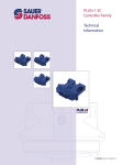
MAKING MODERN LIVING POSSIBLE
Technical Information
PLUS+1 Mobile Machine Displays
DP6XXLX Series
powersolutions.danfoss.com
Technical Information
PLUS+1 Mobile Machine Displays DP6XXLX Series
Revision history
Table of revisions
2
Date
Changed
Rev
August 2014
Converted to Danfoss layout; and various updates
HA
March 2013
Added a note regarding the service tool scan
GA
January 2013
Added monochrome
FA
November 2012
DP610LX input/output options; pin assignments
EA
October 2012
Typo on dimension drawings
DB
July 2012
GPL-License statement, C2 Pin table
DA
May 2012
Model features
CA
May 2012
Typo
BB
April 2012
C4 Pin Function
BA
March 2012
Literature ID number corrected
AB
March 2012
First edition
AA
L1209297 • Rev HA • August 2014
Technical Information
PLUS+1 Mobile Machine Displays DP6XXLX Series
Contents
Literature references
Product overview
Ordering information
Inputs/outputs
Literature types................................................................................................................................................................................. 4
Technical Information (TI)........................................................................................................................................................ 4
Data Sheet (DS)............................................................................................................................................................................ 4
API Specifications (API)............................................................................................................................................................. 4
PLUS+1® GUIDE Software User Manual............................................................................................................................... 4
Literature references....................................................................................................................................................................... 4
Latest version of technical literature......................................................................................................................................... 4
Graphical displays series................................................................................................................................................................ 5
GPL-License (General Public License).................................................................................................................................. 5
User liability and safety statements ..........................................................................................................................................5
OEM responsibility......................................................................................................................................................................5
DP6XXLX naming convention..................................................................................................................................................... 6
Related products...............................................................................................................................................................................7
Assembled mating connector kits........................................................................................................................................ 7
Accessories.................................................................................................................................................................................... 8
Inputs.................................................................................................................................................................................................... 9
Digital/analog...............................................................................................................................................................................9
Multifunction..............................................................................................................................................................................10
Encoder..............................................................................................................................................................................................11
Outputs..............................................................................................................................................................................................11
USB...................................................................................................................................................................................................... 12
Video...................................................................................................................................................................................................12
Controller Area Network (CAN) specifications
CAN shield/analog inputs........................................................................................................................................................... 13
CAN communication.....................................................................................................................................................................13
Gateway channels..........................................................................................................................................................................13
Memory
Product ratings
Housing
Installation
NV memory...................................................................................................................................................................................... 15
FRAM memory........................................................................................................................................................................... 15
Vault memory.............................................................................................................................................................................15
Electrical............................................................................................................................................................................................ 16
Environmental.................................................................................................................................................................................16
Testing criteria.................................................................................................................................................................................16
Assembly...........................................................................................................................................................................................18
Screen.................................................................................................................................................................................................18
Dimensions.......................................................................................................................................................................................19
Two mounting options................................................................................................................................................................ 20
Flush mounted.......................................................................................................................................................................... 20
Stand-alone on post................................................................................................................................................................ 21
Pin assignments..............................................................................................................................................................................22
Wiring................................................................................................................................................................................................. 23
Welding............................................................................................................................................................................................. 23
L1209297 • Rev HA • August 2014
3
Technical Information
PLUS+1 Mobile Machine Displays DP6XXLX Series
Literature references
Literature types
Technical Information (TI)
A TI is comprehensive information for engineering and service personnel to reference.
Data Sheet (DS)
A DS is summarized information and parameters that are unique to a specific model.
API Specifications (API)
An API is specifications for programming variable settings.
API specifications are the definitive source of information regarding pin characteristics.
PLUS+1® GUIDE Software User Manual
This user operation manual (OP) details information regarding the PLUS+1® GUIDE software tool set that
is used to build PLUS+1® applications.
Literature references
References
Literature title
Literature type
Literature number
DP6XXLX Series PLUS+1® Mobile Machine Displays
Technical Information
L1209297
DP600LX Series PLUS+1® Mobile Machine Displays
Data Sheet
L1230993
DP610LX Series PLUS+1® Mobile Machine Displays
Data Sheet
L1222550
DP620LX Series PLUS+1® Mobile Machine Displays
Data Sheet
L1222211
PLUS+1® GUIDE Software User Manual
Operation Manual
10100824
Latest version of technical literature
Up to date technical literature is available at: www.powersolutions.danfoss.com
4
L1209297 • Rev HA • August 2014
Technical Information
PLUS+1 Mobile Machine Displays DP6XXLX Series
Product overview
Graphical displays series
This series of graphical displays is designed to provide mobile machine OEMs with a rugged, high
performing color and monochrome display for both in-cab and open usage.
The transmissive, thin film transistor (TFT), high resolution color display with eight soft-keys and six
buttons for navigation is user-programmable with PLUS+1® GUIDE (Graphical User Integrated
Development Environment).
Use separate mechanical switches to implement critical safety features such as emergency stops.
Communication is done over a Controller Area Network (CAN) system.
GPL-License (General Public License)
This family of products contains embedded Linux operating system software that is copyrighted software
licensed under the GPLv2 or LGPLv2.1. As an installer of this product you will have your own obligations
under the licensing agreements, which may include among other things the obligation to include a copy
of these licenses or to include an offer of a physical copy of the source code for such software with your
distributions of the equipment. You should carefully review the licenses to determine what your
obligations and options may be for your intended use.
For further details, please reference:
http://powersolutions.danfoss.com/Products/MobileElectronics/PLUS1Guide/PLUS1GuideDownloads/
PLUS1GUIDEServiceToolSoftwareLicense/index.htm
User liability and safety statements
OEM responsibility
The OEM of a machine or vehicle in which a Danfoss product is installed has the full responsibility for all
consequences that might occur. Danfoss has no responsibility for any consequences, direct or indirect,
caused by failures or malfunctions.
• Danfoss has no responsibility for any accidents caused by incorrectly mounted or maintained
equipment.
• Danfoss does not assume any responsibility for Danfoss products being incorrectly applied or the
system being programmed in a manner that jeopardizes safety.
• All safety critical systems shall include an emergency stop to switch off the main supply voltage for
the outputs of the electronic control system. All safety critical components shall be installed in such a
way that the main supply voltage can be switched off at any time. The emergency stop must be easily
accessible to the operator.
L1209297 • Rev HA • August 2014
5
Technical Information
PLUS+1 Mobile Machine Displays DP6XXLX Series
Ordering information
DP6XXLX naming convention
Model code
A
B
C
D
E
F
G
D P 6
P200160
This is not a variant configurator.
Product configuration model code
A
B
C
D
E
F
G
Part number
DP600LX
09
02
06
02
04
00
11103049
DP600LX
09
02
06
02
04
04
11100058
DP610LX
10
02
06
02
04
00
11103051
DP610LX
10
02
06
02
04
04
11100060
DP620LX
10
02
06
02
04
01
11100065
A—Model name
Code
Description
DP600LX
PLUS+1® Mobile Machine Displays
DP610LX
DP620LX
B—Input/output options
Code
Description
09
2 CAN, 2 DIN/AIN/FreqIn/Rheo/4-20 mA IN, 2 VideoIn
10
2 CAN, 2 DIN/AIN/FreqIn/Rheo/4-20 mA IN, 2 AIN/CAN Shield
C—Real time clock/low temperature functionality
Code
Description
02
RTC
D—Flash memory/application key
Code
Description
06
512 MB/without application key
E—Application log (vault memory)
Code
Description
02
16 MB
F—USB port type
6
Code
Description
04
USB device rear/USB host rear or front
L1209297 • Rev HA • August 2014
Technical Information
PLUS+1 Mobile Machine Displays DP6XXLX Series
Ordering information
G—Screen size/feature
Code
Description
00
400 x 240 color transflective
01
320 x 240 monochrome transmissive
04
400 x 240 color transflective with anti-fog treatment
Related products
Assembled mating connector kits
Danfoss mating connector kit and contents
Description
Part numbers
Mating connector kit
11109743
Connectors
Binder 5-pin male (USB cable included)
10100728
Binder 8-pin male (USB cable included)
11109742
Deutsch DTM06-6S 6-pin
10103494
Deutsch DTM06-12SA 12-pin (16 to 20
AWG)
10102025
Deutsch DTM06-12SA 12-pin (20 to 24
AWG)
10100944
Terminal
Binder and Deutsch
10100743
Crimp tool
16 to 20 AWG
10100744
20 to 24 AWG
10100745
6-pin Deutsch WM 6S
10100742
12-pin Deutsch WM 12S
10100741
Deutsch
10103495
Binder
10103496
Locking plug
IP 67 Seal Kit
Deutsch® mating connector kits and contents
Description
Part numbers
6-pin connector kit
10103494
DTM06-6S 6-pin connector
10100739
12-pin connector kit (16 to 20 AWG)
10102025
DTM06-12SA 12-pin connector
10100738
12-pin connector kit (20 to 24 AWG)
10100944
DTM06-12SA 12-pin connector
10100738
Terminal Deutsch/Binder
Crimp tool
Locking plug
IP 67 seal kit
L1209297 • Rev HA • August 2014
10100743
16 to 20 AWG
10100744
20 to 24 AWG
10100745
6-pin Deutsch WM 6S
10100742
12-pin Deutsch WM 12S
10100741
Deutsch
10103495
7
Technical Information
PLUS+1 Mobile Machine Displays DP6XXLX Series
Ordering information
Accessories
8
Description
Part number
Panel mounting kit
10101363
USB cable (device only)
10103497
USB cable (device and host)
11109121
Compact color camera, 12 V
10100831
PLUS+1 GUIDE Software Application
(includes Service and Diagnostic Tool, and Screen Editor
10101000
L1209297 • Rev HA • August 2014
Technical Information
PLUS+1 Mobile Machine Displays DP6XXLX Series
Inputs/outputs
Inputs
This series of displays support the following pin types:
• Digital or Analog (DIN/AIN)
•
•
•
Multifunction (DIN/AIN/FreqIN, Rheo, 4–20 mA)
Analog or Temperature or Rheostat (AIN/Temp/Rheo)
Fixed Range Analog or CAN shield (AIN/CAN shield)
This series of displays have input pins that support multiple functions. Pins that support multiple input
types are user-configurable using PLUS+1® GUIDE software.
Digital/analog
Low range multifunction input
Description
Unit
Minimum
Maximum
Comment
Range
mV
0
>350
—
Resolution
mV
0.15
1 mV in software
Worst case error
mV
±(0.15 + U*5/2%)
—
Input impedance
kΩ
230 ± 5
To 0 V
Input impedance with pull-down
kΩ
15 ± 2
To 0 V
Input impedance with pull-up
kΩ
15 ± 2
To 5 V
Input impedance with pull-up/down
kΩ
7.5 ± 1
To 2.5 V
Description
Unit
Minimum
Maximum
Comment
Range
mV
0
>5.5
—
Resolution
mV
2
—
Worst case error
mV
±(20 + U*2%)
—
Input impedance
kΩ
230 ± 5
To 0 V
Input impedance with pull-down
kΩ
15 ± 2
To 0 V
Input impedance with pull-up
kΩ
15 ± 2
To 5 V
Input impedance with pull-up/down
kΩ
7.5 ± 1
To 2.5 V
Description
Unit
Minimum
Maximum
Comment
Range
mV
0
>60
—
Resolution
mV
30
—
Worst case error
mV
±(300 + U*3.8%)
—
Input impedance
kΩ
105 ± 5
To 0 V
Input impedance with pull-down
kΩ
15 ± 2
To 0 V
Input impedance with pull-up
kΩ
15 ± 2
To 5 V
Input impedance with pull-up/down
kΩ
7.5 ± 1
To 2.5 V
Normal range multifunction input
High range multifunction input
L1209297 • Rev HA • August 2014
9
Technical Information
PLUS+1 Mobile Machine Displays DP6XXLX Series
Inputs/outputs
Multifunction
Frequency input low range (ppu)
Description
Unit
Minimum
Maximum
Comment
Range
Hz
0
10000
In steps of 1 Hz
Sensitivity
mVpp
1000
—
Sinus peak-to-peak
Low threshold voltage
mV
75
200
—
High threshold voltage
mV
150
350
—
Input impedance
kΩ
230 ± 5
To 0 V
Input impedance with pull-down
kΩ
15 ± 2
To 0 V
Input impedance with pull-up
kΩ
15 ± 2
To 5 V
Input impedance with pull-up/down
kΩ
7.5 ± 1
To 2.5 V
Description
Unit
Minimum
Maximum
Comment
Range
Hz
0
10000
In steps of 1 Hz
Range (phase and quad)
Hz
0
5000
When measuring phase or
quadrature counts
Low threshold voltage
V
1.1
2.6
—
High threshold voltage
V
2.2
4.4
—
Input impedance
kΩ
230 ± 5
To 0 V
Input impedance with pull-down
kΩ
15 ± 2
To 0 V
Input impedance with pull-up
kΩ
15 ± 2
To 5 V
Input impedance with pull-up/down
kΩ
7.5 ± 1
To 2.5 V
Description
Unit
Minimum
Maximum
Comment
Range
Ω
0
10000
In steps of 1 Ω
Frequency input normal range (ppu)
Resistance input
Resolution
1
@0Ω
2
@ 1 kΩ
42
Source current
@ 10 kΩ
mA
0
4
—
Description
Unit
Minimum
Maximum
Comment
Range
mA
0
50
—
Resolution
μA
22
—
Worst case error
mA
±(0.2 + I*3%)
—
Input impedance
Ω
100 ± 3
To 0 V
Shut-off current
mA
54
—
4–20 mA input
This product does not have a Real Time Operating System (RTOS). Frequency inputs are managed by the
operating system. Because of this you should avoid using these inputs for any type of Safety Critical
closed loop control as the accuracy maybe affected by processor load. They should only be used for nonsafety critical related functions.
10
L1209297 • Rev HA • August 2014
Technical Information
PLUS+1 Mobile Machine Displays DP6XXLX Series
Inputs/outputs
High level digital input
Description
Unit
Minimum
Maximum
Typical
Comment
Voltage range
V
0
63
—
—
Input resistance
kΩ
—
—
105
No pull-up/down
13
With pull-up to 5 V
13
Pull-down to ground
7
With pull-up and down to 5 V
Programmable low
threshold voltage
V
0
63
—
—
Programmable high
threshold voltage
V
0
63
—
—
Rise time
μs
—
—
20
—
Fall time
μs
—
—
20
—
Description
Unit
Minimum
Maximum
Typical
Comment
Voltage range
V
0
63
—
—
Input resistance
kΩ
—
—
105
No pull-up/down
13
With pull-up to 5 V
13
Pull-down to ground
High level analog input
Analog voltage error
(± 300 mV + Uin x 3.4%)
mV
Bandwidth
kHz
—
—
—
—
7
With pull-up/down to 5 V
± 100
Uin = 0 V
± 2760
Uin = 70 V
7.1
—
Encoder
The encoder input is only suitable for user interface functions, such as, navigating in menus and adjusting
values because there is no guarantee that all pulses are detected and the detected direction can be false.
The rate of pulses should be kept at a few tens per second to minimize the loss of detected position
changes.
The encoder function samples the A and B signals from the encoder and increments or decrements the
counter according to the phase sequence. The counter is incremented/decremented on every low to
high and high to low edge of the A signal. Some encoders with detents give a complete pulse between
detents and the counter will be incremented/decremented by two for every detent. The counter is
incremented when the A signal is the leading phase and decremented in the opposite case.
Outputs
Digital output
Descripton
Unit
Minimum value
Maximum value
Output current range A
0
1
Short circuit current
A
—
2
Short circuit current
peak
A
—
8
Saturation voltage
V
—
1
L1209297 • Rev HA • August 2014
Comment
At 1 A
11
Technical Information
PLUS+1 Mobile Machine Displays DP6XXLX Series
Inputs/outputs
Digital output (continued)
Descripton
Unit
Minimum value
Maximum value
Current
measurement
A
0
2
Current
measurement error
mA
—
±
Comment
At 1 A
USB
USB input/output
Description
Unit
Minimum
Maximum
Typical
Comment
2.0 full speed
Mbit/s
—
—
12
—
Vbus input voltage
V
—
—
> 4.4
—
Vbus input resistance
kΩ
—
—
70
Vbus < 5.25 V
Short circuit protection
(No damage)
V
0
70
—
—
Vbus output voltage
V
4.75
5.25
—
—
Vbus output current
A
—
—
0.5
—
Vbus short current
A
—
1.1
—
—
This series of displays all have USB ports that support memory sticks and computer connection. The
display functions as a device when connected to a computer for diagnosis purposes or software
download. The display functions as a host when a standard USB memory stick is connected so log-data
can be transferred.
Other than supporting memory sticks and computer connection, this display series USB port does not
support any other standard computer peripherals.
Video
Video output
12
Description
Unit
Minimum
Maximum
Typical
Comment
Short circuit protection
V
0
70
—
—
12 V output voltage
(9 V < Ubat < 70 V)
V
11.5
12.7
12
—
12 V output current
A
—
—
0.5
Vbus < 5.25 V
24 V output voltage
(9 V < Ubat < 70 V)
V
23
26
24
—
24 V output current
A
—
0.5
—
—
External video inputs
—
—
—
—
Both NTSC and PAL support
L1209297 • Rev HA • August 2014
Technical Information
PLUS+1 Mobile Machine Displays DP6XXLX Series
Controller Area Network (CAN) specifications
CAN shield/analog inputs
The CAN shield pin on the unit can be used as a non-configurable analog input.
The values in the following table assumes that software compensates for errors in the analog to digital
(A/D) converter.
CAN shield
Description
Unit
Minimum
Maximum
Typical
Comment
Input impedance
—
—
—
1 μF + 1 Ω
—
Analog input (5 V only)
Description
Unit
Minimum
Maximum
Comment
Allowed voltage at pin
V
0
70
—
Measuring range
V
0
> 5.5
—
Resolution
mV
2
—
Worst case error
mV
±(20 + U*2%)
—
Input impedance
kΩ
230 ± 5
—
CAN communication
CAN communication
Description
Unit
Minimum
Maximum
Available baud rates
kBd
50
1000
Typical
Comment
50
With 120 Ω termination
100
125
250
500
1000
Maximum input voltage
range
V
0
70
—
—
Gateway channels
PLUS+1® GUIDE Service Tool can be connected to the CAN bus by using the following gateway channels.
Gateway channels
Channel
Description
0
DP600 only
1
DP600 + CAN0
2
DP600 + CAN1
3
DP600 + CAN0+1
4
CAN0
5
CAN1
6
CAN0+1
L1209297 • Rev HA • August 2014
13
Technical Information
PLUS+1 Mobile Machine Displays DP6XXLX Series
Controller Area Network (CAN) specifications
Selecting channel zero will not increase CAN traffic because of the PLUS+1® GUIDE Service Tool
communication.
Another PLUS+1® GUIDE Service Tool can be connected to the CAN bus by using the following gateway
channels.
Simultaneous usage Gateway channels
14
Channel
Description
0
CAN[0] and CAN[1]
1 or 4
CAN[1]
2 or 5
CAN[0]
3 or 6
No CAN port
L1209297 • Rev HA • August 2014
Technical Information
PLUS+1 Mobile Machine Displays DP6XXLX Series
Memory
NV memory
C
Caution
Non-volatile (NV) memory data loss is possible when the NV write cycle is not fully completed. When
downloading a new application ensure data is not being written to NV memory.
FRAM memory
This series of displays use Ferroelectric Random Access Memory (FRAM). FRAM has a write endurance of
over 100 trillion cycles, that is ideal for datalogging.
Vault memory
This series of displays have 16 MB of serial flash vault memory (application logging memory). Application
developers use this memory to log machine event data then use a USB stick or the PLUS+1® Service Tool
to extract the logged data.
Accessing non-volatile or application log memory can delay the service tool scan.
L1209297 • Rev HA • August 2014
15
Technical Information
PLUS+1 Mobile Machine Displays DP6XXLX Series
Product ratings
Electrical
Supply voltage
Description
Unit
Minimum
Maximum
Comment
DC supply voltage
V
9
63
With reverse polarity protection
DC supply current (circuit board only)
A
0
1
UBat = 14 V
0
0.5
UBat = 28 V
—
—
200 ms
Power supply interruption (without
rebooting)
ms
5 V reference output
Description
Unit
Minimum
Maximum
Output voltage
V
4.8
5.2
Output current
A
0
0.5
Output short circuit
A
—
1
Short circuit protection
V
0
70
W
Warning
Output pins produce high voltage. High voltage can cause fire and/or electrical shock, if flammable
gasses or chemicals are present, can cause an explosion. To protect against product damage and possible
injury, do not exceed power supply voltage ratings and do not store this product where flammable
gasses or chemicals are present.
Environmental
General
Description
Operating
temperature
Units
Minimum
Maximum Comment
DP600LX and
DP610LX
˚C [˚F]
-30 [-22]
70 [158]
—
DP620LX
˚C [˚F]
-20 [-4]
70 [158]
—
˚C [˚F]
-40 [-40]
85 [185]
—
Storage
temperature
W
Warning
Excessive high/low operating/storage temperatures can damage electronics. Damaged electronics can
result in performance failure. To protect against product damage and possible injury, do not operate/
store product in a environment that exceeds specified temperature ratings.
Testing criteria
Climatic
16
Condition
Rating
Cold/heat storage and operation
IEC 60068-2-1, IEC 60068-2-2
Fogging
IEC 60068
L1209297 • Rev HA • August 2014
Technical Information
PLUS+1 Mobile Machine Displays DP6XXLX Series
Product ratings
Climatic (continued)
Condition
Rating
Temperature change
IEC 60068-2-14
Moisture ingress
IEC 60529
Sunlight visibility
IEC 68-2-5
Chemical
Condition
Rating
Chemical resistance
ISO 16750-5
Mechanical
Condition
Rating
Vibration, resonance
IEC 60068-2-6
Vibration, operation
IEC 60068-2-64
Bump
IEC 60068-2-29
Shock
IEC 60068-2-27
Free fall
IEC 60068-2-32
L1209297 • Rev HA • August 2014
17
Technical Information
PLUS+1 Mobile Machine Displays DP6XXLX Series
Housing
Assembly
The housing comes pre-assembled. PLUS+1 mobile machine displays feature a snap together assembly
that is tamper-proof.
Opening the display’s housing voids the factory warranty.
Screen
W
Warning
Prolonged exposure to direct intense sunlight can cause premature failure of the LCD module. This risk
can be reduced by providing shading or mounting the display at an incline rather than the horizontal.
There is protective glass over the display screen.
C
Caution
The protective glass will break if hit with a hard or heavy object. If the protective glass is broken, remove
the display from your machine then return the display to Danfoss to be serviced.
Clean the display’s housing and protective glass with a clean, soft, damp cloth, or mild dishwashing
detergent because abrasive pads or solvents, including alcohol, benzene, and paint thinner can cause
scratching and discoloration.
18
L1209297 • Rev HA • August 2014
Technical Information
PLUS+1 Mobile Machine Displays DP6XXLX Series
Installation
Dimensions
DP600LX and DP610LX (mm [in])
225.0 ± 0.5
[8.858 ± 0.02]
155.0 ± 0.5
[6.102 ± 0.02]
13.3 ± 0.5
[0.524 ± 0.02]
51.2 ± 0.5
[2.016 ± 0.02]
165.10
[6.50]
55.2 ± 0.5
[2.173 ± 0.02]
P200095
DP620LX (mm [in])
225.0 ± 0.5
[8.858 ± 0.02]
155.0 ± 0.5
[6.102 ± 0.02]
13.3 ± 0.5
[0.524 ± 0.02]
51.2 ± 0.5
[2.016 ± 0.02]
144.78
[5.70]
55.2 ± 0.5
[2.173 ± 0.02]
P200096
L1209297 • Rev HA • August 2014
19
Technical Information
PLUS+1 Mobile Machine Displays DP6XXLX Series
Installation
Two mounting options
Flush mounted
Use the Danfoss spring clip frame to flush-mount into a dashboard.
Panel cutout (mm [in] and spring clip
210.00 ± 0.50
[8.268 ± 0.02]
20.00 ± 0.50
[0.79 ± 0.02]
5
6
7
4.20 ± 0.50
[0.17 ± 0.02]
145.00 ± 0.50
[5.71 ± 0.02]
2
105.00 ± 0.50
[4.13 ± 0.02]
4
201.50 ± 0.50 panel cutout
[7.93 ± 0.02]
1
3
P200161
Flush mounting callouts
20
Callouts
Description
1
4 x hole for M4 screw
2
Panel cutout
3
Display assembly
4
Snap in
5
4 x M4 screw
6
Spring clip
7
Panel
L1209297 • Rev HA • August 2014
Technical Information
PLUS+1 Mobile Machine Displays DP6XXLX Series
Installation
Stand-alone on post
Mount according to VESA (Video Electronics Standards Association) Mount Standards The VESA hole
pattern for this display is: 75.00 mm x 75.00 mm (02.95 in x 02.95 in).
Stand alone on post mounting option (mm [in])
1
75.00 ± 0.50
[2.95 ± 0.02]
75.00 ± 0.50
[2.95 ± 0.02]
23.50 ± 0.50
[0.93 ± 0.02]
75.00 ± 0.12
[2.95 ± 0.005]
P200161
Stand alone on post mounting callout
Callout
Description
1
4 x hole for M4 screw x 0.7 mm (0.03 in) x 11 mm (0.43 in) maximum depth
Disconnect your machine’s battery power before connecting power and signal cables to the display.
L1209297 • Rev HA • August 2014
21
Technical Information
PLUS+1 Mobile Machine Displays DP6XXLX Series
Installation
Pin assignments
DP6XXLX series, pin assignments
C1-P12
C4-P1
C4
C4-P5
C3-P1
C2
C3
C1-P1
C2-P6
C3-P8
C2-P1
C1
P200162
Pin connectors
C4
C3
C2
C1
P200163
Pin assignments
Binder 702 series 5-pin
Binder 702 series 8-pin
Deutsch DTMO6 6-pin
Deutsch DTMO6 12-pin
C4 pin
Function
C3 pin
Function
C2 pin
Function
C1 pin
Function
1
Power Ground
1
USB Device Vbus
1
Battery Ground
1
Power ground -
2
Power Supply
2
USB Device Data -
2
Redundant Power Supply
2
Power ground +
3
Video 1 In
3
USB Device Data +
3
NC
3
CAN1 High +
4
Signal Ground
4
USB Device Ground
4
NC
4
CAN1 Low -
5
Video 2 In
5
USB Host Ground/RS232
5
CAN Shield/AIN
5
AIN/CAN Shield
6
USB Host Data +/RS232 RxD
6
Digital/AIN
6
CAN0 High +
7
USB Host Data -/RS232 TxD
7
CAN0 Low -
8
USB Host Vbus
8
Sensor Supply
9
Multifunction-Input
10
Multifunction-Input
11
Analog/Digital
Input
12
Digital Output
22
L1209297 • Rev HA • August 2014
Technical Information
PLUS+1 Mobile Machine Displays DP6XXLX Series
Installation
Wiring
1. All wires must be protected from mechanical abuse. Wires should be run in flexible metal or plastic
conduits.
2. Use 85˚ C [185˚ F] wire with abrasion resistant insulation. 105˚ C [221˚ F] wire should be considered
near hot surfaces.
3. Use a wire size that is appropriate for the module connector.
4. Separate high current wires such as solenoids, lights, alternators or fuel pumps from sensor and other
noise-sensitive input wires.
5. Run wires along the inside of, or close to, metal machine surfaces where possible. This simulates a
shield which will minimize the effects of EMI/RFI radiation.
6. Do not run wires near sharp metal corners. Consider running wires through a grommet when
rounding a corner.
7. Do not run wires near hot machine members.
8. Provide strain relief for all wires.
9. Avoid running wires near moving or vibrating components.
10. Avoid long, unsupported wire spans.
11. All analog sensors should be powered by the sensor power source from the PLUS+1 controller and
ground returned to the sensor ground pin on the PLUS+1 controller.
12. Sensor lines should be twisted about one turn every 10 cm [4 in].
13. It is better to use wire harness anchors that will allow wires to float with respect to the machine rather
than rigid anchors.
14. Electronic modules should be grounded to a dedicated conductor of sufficient size that is connected
to the battery (-).
Welding
W
Warning
Power and signal cables produce high voltage. High voltage can cause fire and/or electrical shock, if
flammable gasses or chemicals are present, can cause an explosion. To protect against product damage
and possible injury, before doing any electrical welding on a machine, disconnect all power and signal
cables connected to the display.
1. The engine should be off.
2. Disconnect the negative battery cable from the battery.
3. Do not use electrical components to ground the welder. Clamp the ground cable for the welder to
the component that will be welded as close a possible to the weld.
L1209297 • Rev HA • August 2014
23
Products we offer:
•
•
•
•
•
•
•
•
•
•
•
•
•
•
•
•
Bent Axis Motors
Closed Circuit Axial Piston
Pumps and Motors
Displays
Electrohydraulic Power
Steering
Electrohydraulics
Danfoss Power Solutions is a global manufacturer and supplier of high-quality hydraulic and
electronic components. We specialize in providing state-of-the-art technology and solutions
that excel in the harsh operating conditions of the mobile off-highway market. Building on
our extensive applications expertise, we work closely with our customers to ensure
exceptional performance for a broad range of off-highway vehicles.
We help OEMs around the world speed up system development, reduce costs and bring
vehicles to market faster.
Danfoss – Your Strongest Partner in Mobile Hydraulics.
Hydraulic Power Steering
Go to www.powersolutions.danfoss.com for further product information.
Integrated Systems
Wherever off-highway vehicles are at work, so is Danfoss. We offer expert worldwide support
for our customers, ensuring the best possible solutions for outstanding performance. And
with an extensive network of Global Service Partners, we also provide comprehensive global
service for all of our components.
Joysticks and Control
Handles
Microcontrollers and
Software
Open Circuit Axial Piston
Pumps
Orbital Motors
Please contact the Danfoss Power Solution representative nearest you.
PLUS+1® GUIDE
Proportional Valves
Sensors
Steering
Transit Mixer Drives
Comatrol
www.comatrol.com
Schwarzmüller-Inverter
www.schwarzmuellerinverter.com
Local address:
Turolla
www.turollaocg.com
Valmova
www.valmova.com
Hydro-Gear
www.hydro-gear.com
Daikin-Sauer-Danfoss
www.daikin-sauer-danfoss.com
Danfoss
Power Solutions US Company
2800 East 13th Street
Ames, IA 50010, USA
Phone: +1 515 239 6000
Danfoss
Power Solutions GmbH & Co. OHG
Krokamp 35
D-24539 Neumünster, Germany
Phone: +49 4321 871 0
Danfoss
Power Solutions ApS
Nordborgvej 81
DK-6430 Nordborg, Denmark
Phone: +45 7488 2222
Danfoss
Power Solutions
(Shanghai) Co., Ltd.
Building #22, No. 1000 Jin Hai Rd
Jin Qiao, Pudong New District
Shanghai, China 201206
Phone: +86 21 3418 5200
Danfoss can accept no responsibility for possible errors in catalogues, brochures and other printed material. Danfoss reserves the right to alter its products without notice. This also applies to
products already on order provided that such alterations can be made without changes being necessary in specifications already agreed.
All trademarks in this material are property of the respective companies. Danfoss and the Danfoss logotype are trademarks of Danfoss A/S. All rights reserved.
L1209297 • Rev HA • August 2014
www.danfoss.com
© Danfoss A/S, 2014