1
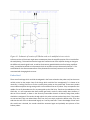
Recommendations for Future Work
Microfluidics
The microfluidics mask design provided fully functional fluid flow for both passive and active methods,
although finding a solution to why fluid will not flow passively on a chip remains to be investigated. As
described previously, there were complications in achieving a permanent bond with plasma oxidation on
the most recent, working chips for reasons not completely understood. It is possible that obtaining a
better understanding of the differences in surface chemistry between the old and new chips would
explain this phenomenon. In the future, having a new mask design with either 0.8 mm reservoirs or
with the reservoirs completely removed would be convenient to have as different fluid flow methods
require different sized punches. For example, active flow using PEAK tubing requires a 0.8 mm punch on
each end of the channel while passive flow requires a 1.5 mm inlet reservoir and a 1.0 mm outlet
reservoir.
Another potential area for future work in the design and integration of microfluidics lies in simulations.
It would be helpful to use a program like Fluent to simulate the flow patterns. In addition, in
conjunction with the apparatus setup, it would be useful to gain more insight into the temperature
changes incurred by lengthy exposure to the microscope light during positioning and how long it
subsequently takes for the device to return to room temperature. In the distant future, it will be
necessary to devise a reconfiguration of the probe station to accommodate fluid flow through several
channels for sample delivery to multiple sections of a waveguide. Finally, in conjunction with work on
biomolecules and antigen-antibody bonding, calculations and experiments should be conducted in an
attempt to determine approximate diffusion and kinetics properties of tuberculosis molecules between
the microfluidic channels and the waveguide surface.
Biomolecular Printing
Biomolecular printing still needs to be improved for use in the LEAC chip system. Due to the inability to
use the electronic printer, the PMDS punch printing method has the greatest likelihood for success in
this system. This method however still offers problems that need to be addressed for full system
integration to be possible.
The accuracy and repeatability of the alignment of the two printing step is crucial for this method to
allow for reliable data to be taken from the LEAC chip. A more consistent method for creating the first
dimension printing pattern would increase accuracy greatly. A mask design and mold for this piece of
PDMS, with the reservoirs measured out to exactly correspond with the widening in the channels would
be a large improvement on the previous method of marking the areas with a permanent marker. This
would allow for precise punches for the first dimension printing that correspond directly with the
second dimension channels. It would still be very important to ensure that the two PDMS stamps are
aligned with each other when they are put onto the chip. The aligner makes this accurate, but practice
and perhaps improvement in this technique would improve alignment.
Another, and potentially more detrimental problem, is that of the inability to permanently bond PDMS
to surface with biomolecules already attached. It was found that in order to use the syringe pump and
tubing system a permanent bind between the PDMS and the LEAC chip was important. The tubing
system will pull PDMS that is not permanently bound off of the LEAC chip, and for real-time data, it is
imperative that the second dimension PDMS channels stay attached. However, to get a permanent bind
between PDMS and a chip, both surfaces need to be placed in the plasma chamber, which is impossible
with the previously printed first dimension of antigens. The plasma treatment would ruin the first
dimension patterning. Unless a way to avoid a need for permanent binding within the system is
discovered, this problem may be cause for finding a new form of microfluidic channels that does not
involve PDMS stamps.
Probe Station
Future work on the probe station should make the system as a whole more user friendly and easier to
align and manipulate. The recent addition of translation stages under the fiber launch and probe card
attempted to meet that need but are lacking in some ways. The translation stage under the probe card
is probably a good solution for that particular part, however, the translation stages under the fiber
launch are rather slow moving and difficult to reach. In addition, the sample holder is still not fixed to
the base plate of the probe station. Using rail type control stages may be a good way to provide the
desired freedoms and make the station more usable. The advantage of rail type control stages is that
they are quicker and easier to adjust and generally have an increased range of travel compared to
micrometer controlled translation stages. One possible configuration would be to add one rail type
control stage under the sample holder and another under the fiber launch. The one under the sample
holder would be used for coarse adjustment in the Y direction of the sample to the fiber. The one under
the fiber launch would allow coarse X direction adjustment. Fine adjustments would then be performed
using the micrometer controlled XYZ capability of the two pieces.
The other probe station problem that should be addressed by future work is accessing waveguides 2 and
6. As detailed in the probe station user’s manual, the current probe station hardware cannot access
these two waveguides on a PDMS bonded LEAC sample. This is due to the configuration of the LEAC
sample contact areas, waveguide entrances and probe card probes. To allow the various pieces of
hardware to fit in Configuration 3 as defined in the probe station user’s manual, the fiber launch should
be adjusted in such a way that makes part of it lower with respect to the plane of the probe card and
sample. However, part of it will still need to be at the same height as the sample to allow coupling of the
laser into the waveguide. This would allow the fiber launch to sit under the probe card safely while
retaining the necessary function.
LabVIEW Programming
LabVIEW is a powerful tool that can interface with hardware devices, automate experiments, and
capture data. There are many things that can be done in the future to help with the program moving
forward. However, the best approach would probably be to start the program over from scratch. The
program used was based on LabVIEW 8.5 which is a fairly old version. Unfortunately this version has
caused the program to no longer open correctly when used with any version of LabVIEW 2011. After
getting a feel for the sort of experiments and forward progress that wants to be made, the biggest
choice that will be made is what kind of data the group wants captured through the program. There are
a few key components, in which the user interface needs to give the user meaningful real time data, the
program needs to save data in a useful format, and the code should be combined with MATLAB to
automate data processing (Perhaps it should be looked into not using LabVIEW at all and interfacing to
the devices with MATLAB).
An addition that needs to be added to the LabVIEW control interface is a manual, real time selection of
channels. As of now a person can only sweep through channels, making it cumbersome to debug
individual pads or probes. The reference channel logging is also currently inoperable and needs to be
fixed. Currently when the program logs the reference channel measurement it only saves it to the
nearest integer, removing any usefulness. Finally, a feature should be added that displays a graph with
the history of the channel that can be used to compare with the current channel so that drift can be
observed in real time and adjusted for accordingly.
Saving the data in a useful format is another consideration. It is important that all of the raw data is
saved for the entire run, not just the mean and standard deviation. Any future revisions of the code will
need to ensure that all data is saved in a coherent manner for both the signal channels and the
reference channels if used).
The last and possibly most major improvement would be the incorporation of MATLAB '.m' files as
blocks within the LabVIEW interface. It could then handle the data directly and process it in real time
enabling the user to know the results of the experiment as it is happening. This would allow for better
response to experimental setup errors as well as save a lot of time that is currently needed for data
manipulation and analysis after the experiment has already been completely performed.
Multiplexing/Amplification Circuit
The current multiplexer and amplification circuit appears to be working great and probably does not
need any revisions done to it until other parts of the system are developed more. One modification that
may want to be made is the inversion of the amplification circuit. In order to achieve this, the jumper
must be placed on the board and pin 1 of IC2 needs to be lifted up from the board (See Figure 0-1). This
will result in increasing voltages for increasing currents which may make data collection more straight
forward. The PCB design solved most of the problems encountered early on in the year. The schematic
is located in Appendix F as well as in electronic form in the lab on the senior design CD. Any future
revisions of the probe card should be made by modifying the current schematic and PCB design in
Advanced Circuits PCB artist.
Figure 0-1: Schematic of location of PCB that needs to be modified to invert circuit
A future revision of the circuit might want to attempt to place the amplifier portion of the circuit before
the multiplexing. This would remove the large time constant issue of the amplifier having to change to
the different channels signal levels, as well as eliminate any possible MUX noise from being amplified.
Lastly, it would be beneficial to incorporate the lock-in amplifier set up as discussed in Section II. This
would allow for the direct measurement of the photocurrent and may remove a lot of confusion
associated with changing dark currents.
Probe Card
There are a few things which could be investigated in the future related to the probe card, but these are
unlikely critical to the project. One of the things which could be first investigated, if it is shown to be
necessary, is looking into how to fix the currently bent probes on the probe card. These seven probes
were inadvertently bent during testing and lie in the middle of the set of probes. They correspond to the
middle of a set of photodetectors for any waveguide on the LEAC chip. Thanks to the redundancy of the
LEAC chip, it is not imperative that these probes get fixed in order to collect useful data. However, if
data on more channels, or data on the currently inaccessible channels is desired, fixing these probes
should be investigated. The vendor through which this probe card was ordered says that, if the probes
are not too bent, they can unbend them and if not, they can simply replace the broken ones. They also
said that the cost of this is determined largely on a case-by-case basis. If more knowledge of how much
this would cost is desired, the vendor should be contacted again and probably sent pictures of the
broken probes.
An important thing to keep in mind with the probe card is that its probes require periodic cleaning in
order to maintain function. Currently, the probes on the probe card are tungsten probes which are
relatively fibrous and prone to collecting oxides from the aluminum pads they connect to. When a
significant amount of oxides or other debris are collected in the probes, it can destroy functionality and
consistency of testing. To fix this, the probes should be cleaned when contact issues are a noticeable
problem or noisy data on channels that used to not be so noisy becomes apparent. There are a few easy
ways to clean these probes. One is by rubbing 3 microns grit, silicon type lapping paper (like sand paper)
across the probes to dislodge oxide. This was the only method used for cleaning the probes previously
and seemed to work fairly well. If a different method is desired, or this one proves to be ineffective
sometime, one should contact the vendor to determine what to do.
If a new probe card is ever ordered, there are a few things which could be done differently and would
possibly be beneficial. The first is changing the type of probes from tungsten to tungsten-rhenium.
Tungsten-rhenium probes are less fibrous and not as prone to collecting oxides as tungsten probes. This
means they require less time between cleaning and possibly last longer. Another thing which should be
investigated is the exact location at which the edge sensors are placed on the probe card. Currently,
they are sometimes close to coming in contact with a waveguide on the LEAC chip when they are set
down. It is very undesirable to come down with a probe on one of the fragile waveguides. Avoiding this
is relatively simple, since the waveguides are so small, but to make sure this does not happen if a new
probe card is ordered, other positions should be looked into.
Team Management
One hindrance to the project’s progress this past year was the learning curve for the new team
members and the time it took each to get up to speed on the theory, technology, and laboratory
techniques required by the device. It would be useful to spend the first month or two reading papers,
presenting materials, and learning basic science techniques in the laboratory as opposed to learning
them haphazardly and individually along the way. In addition, while experiments are critical to progress,
it would have been useful to the validation of conclusions if the experimental work were supported by
analytical solutions and simulations. In terms of weekly meeting times, revisions should be made to the
team meeting structure to yield more efficient communication and progress. While it is still relevant to
alternate team leadership responsibilities, it would be useful for all team members if more formal
presentations of results were required at weekly meetings and all deliverables included with weekly
progress reports. It might also be useful to move these meetings from the middle of the working week
to the very beginning in order to more clearly define goals and strategies for each week. The Gantt
chart was useful and should remain an integral component of the project management. Finally, if the
team is to remain interdisciplinary, recruitment of advisers from the chemical engineering and the
mechanical engineering departments could provide invaluable advice and support.