1
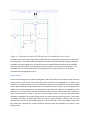
Figure 0-1: Schematic of location of PCB that needs to be modified to invert circuit
A future revision of the circuit might want to attempt to place the amplifier portion of the circuit before
the multiplexing. This would remove the large time constant issue of the amplifier having to change to
the different channels signal levels, as well as eliminate any possible MUX noise from being amplified.
Lastly, it would be beneficial to incorporate the lock-in amplifier set up as discussed in Section II. This
would allow for the direct measurement of the photocurrent and may remove a lot of confusion
associated with changing dark currents.
Probe Card
There are a few things which could be investigated in the future related to the probe card, but these are
unlikely critical to the project. One of the things which could be first investigated, if it is shown to be
necessary, is looking into how to fix the currently bent probes on the probe card. These seven probes
were inadvertently bent during testing and lie in the middle of the set of probes. They correspond to the
middle of a set of photodetectors for any waveguide on the LEAC chip. Thanks to the redundancy of the
LEAC chip, it is not imperative that these probes get fixed in order to collect useful data. However, if
data on more channels, or data on the currently inaccessible channels is desired, fixing these probes
should be investigated. The vendor through which this probe card was ordered says that, if the probes
are not too bent, they can unbend them and if not, they can simply replace the broken ones. They also
said that the cost of this is determined largely on a case-by-case basis. If more knowledge of how much
this would cost is desired, the vendor should be contacted again and probably sent pictures of the
broken probes.