1
getting a feel for the sort of experiments and forward progress that wants to be made, the biggest
choice that will be made is what kind of data the group wants captured through the program. There are
a few key components, in which the user interface needs to give the user meaningful real time data, the
program needs to save data in a useful format, and the code should be combined with MATLAB to
automate data processing (Perhaps it should be looked into not using LabVIEW at all and interfacing to
the devices with MATLAB).
An addition that needs to be added to the LabVIEW control interface is a manual, real time selection of
channels. As of now a person can only sweep through channels, making it cumbersome to debug
individual pads or probes. The reference channel logging is also currently inoperable and needs to be
fixed. Currently when the program logs the reference channel measurement it only saves it to the
nearest integer, removing any usefulness. Finally, a feature should be added that displays a graph with
the history of the channel that can be used to compare with the current channel so that drift can be
observed in real time and adjusted for accordingly.
Saving the data in a useful format is another consideration. It is important that all of the raw data is
saved for the entire run, not just the mean and standard deviation. Any future revisions of the code will
need to ensure that all data is saved in a coherent manner for both the signal channels and the
reference channels if used).
The last and possibly most major improvement would be the incorporation of MATLAB '.m' files as
blocks within the LabVIEW interface. It could then handle the data directly and process it in real time
enabling the user to know the results of the experiment as it is happening. This would allow for better
response to experimental setup errors as well as save a lot of time that is currently needed for data
manipulation and analysis after the experiment has already been completely performed.
Multiplexing/Amplification Circuit
The current multiplexer and amplification circuit appears to be working great and probably does not
need any revisions done to it until other parts of the system are developed more. One modification that
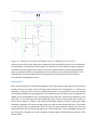
may want to be made is the inversion of the amplification circuit. In order to achieve this, the jumper
must be placed on the board and pin 1 of IC2 needs to be lifted up from the board (See Figure 0-1). This
will result in increasing voltages for increasing currents which may make data collection more straight
forward. The PCB design solved most of the problems encountered early on in the year. The schematic
is located in Appendix F as well as in electronic form in the lab on the senior design CD. Any future
revisions of the probe card should be made by modifying the current schematic and PCB design in
Advanced Circuits PCB artist.