1
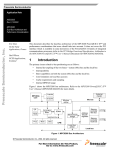
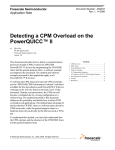
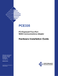
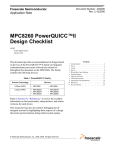
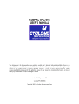
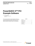
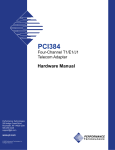
Freescale Semiconductor, Inc.
Addendum
MPC8260AUMAD/D
Rev. 0.1, 2/2002
Freescale Semiconductor, Inc...
MPC8260 PowerQUICC II™
User’s Manual:
MPC8260A (HiP4)
Supplement
This document describes implementation of the MPC8260A—the HiP4-process technology
version of the MPC8260 PowerQUICC II microprocessor—and differences between the
MPC8260A the MPC8260 (HiP3 version). All of the information in the MPC8260
PowerQUICC II User’s Manual (which applies to the HiP3 process) also applies to the
MPC8260A with the exceptions and additions noted in this document. In the event
information in the two documents conflict, information presented here supersedes that in the
MPC8260 PowerQUICC II User’s Manual.
NOTE
Section, table, and figure numbering in this document
indicates the chapter in the MPC8260 PowerQUICC II
User’s Manual to which each item corresponds. HiP4
additions and changes do not pertain to all chapters;
therefore, not all chapters are referred to in this document.
A revision history of this document is provided at the end.
MPC826xA Devices and Documentation
Motorola offers four HiP4-enhanced derivatives of the MPC8260 PowerQUICC II family.
Table 1 shows the functionality that defines each derivative.
Table 1. HiP4 MPC826xA PowerQUICC II Family Derivatives
Derivatives
Functionality
MPC8260A MPC8264A MPC8265A MPC8266A
HiP4 Process Enhancements
X
X
PCI Bridge
X
X
X
X
Transmission Convergence (TC) Layer
X
X
Inverse Multiplexing for ATM (IMA)
X
X
Until the current MPC8260 PowerQUICC II User’s Manual (Rev 0) is updated, several
addendum documents like this one supply information about the functionality of
HiP4-enhanced PowerQUICC II devices. Table 2 lists each device and its related
documentation.
For More Information On This Product,
Go to: www.freescale.com
Freescale Semiconductor, Inc.
Overview (Chapter 1)Features
Table 2. HiP4 PowerQUICC II Documentation1
Derivatives
Document
MPC8260A MPC8264A MPC8265A MPC8266A
MPC8260 PowerQUICC II User’s Manual, Rev 0
(Document order number: MPC8260UM/D)
X
X
X
X
Errata to the MPC8260 PowerQUICC II User’s Manual
(Document order number: MPC8260UMAD/D)
X
X
X
X
MPC8260A (HiP4) Supplement to the MPC8260
PowerQUICC II User’s Manual (Preliminary)
(Document order number: MPC8260AUMAD/D)
X
X
X
X
X
X
Freescale Semiconductor, Inc...
PCI Bridge Functional Specification (Preliminary)
(Document order number: MPC8265AUMAD/D)
TC Layer Functional Specification (Preliminary)
(Document order number: MPC8264AUMAD/D)
X
X
IMA Functional Specification (Preliminary)
(Document order number: MPC8266AUMAD/D)
X
X
1
These documents are available at www.motorola.com/semiconductors.
Overview (Chapter 1)
This section summarizes new features of the MPC8260A (see Figure 1-1).
1.1 Features
The major additional features of the MPC8260A are as follows:
•
Major new CPM features:
— 32-Kbyte dual-port RAM
— Additional MCC host commands
1.2 MPC826xA Architecture Overview
Figure 1-1 shows the block diagram for the MPC8266A, the superset device.
2
MPC8260 PowerQUICC II™ User’s Manual: MPC8260A (HiP4) Supplement
For More Information On This Product,
Go to: www.freescale.com
MOTOROLA
Freescale Semiconductor, Inc.
Memory Map (Chapter 3)MPC826xA Architecture Overview
16 Kbytes
I-Cache
I-MMU
System Interface Unit
(SIU)
G2 Core
16 Kbytes
D-Cache
Bus Interface Unit
PCI Bus2,3
32 bits, up to 66 MHz
60x-to-PCI
Bridge2,3
60x-to-Local
Bridge
D-MMU
Communication Processor Module (CPM)
60x Bus
or
Local Bus
32 bits, up to 83 MHz
Memory Controller
Timers
Serial
DMAs
32 Kbytes
Dual-Port RAM
Interrupt
Controller
Clock Counter
Freescale Semiconductor, Inc...
Parallel I/O
32-bit RISC Microcontroller
and Program ROM
Baud Rate
Generators
MCC1
MCC2
4 Virtual
IDMAs
1,3
IMA
Microcode
FCC1
FCC2
FCC3
SCC1
TC Layer Hardware1,3
SCC2
SCC3
SCC4
System Functions
SMC1
SMC2
SPI
I2C
Time Slot Assigner
Serial Interface
3 MII
Ports
8 TDM Ports
2 UTOPIA
Ports
Non-Multiplexed
I/O
Notes
1. MPC8264A
2. MPC8265A
3. MPC8266A
Figure 1-1 MPC826xA Block Diagram
Memory Map (Chapter 3)
Table 3-1 shows the HiP4 additions to the internal memory map of the MPC8260A. Note that PCI and TC
layer portions of the memory map can be found in separate documentation (see Table 2).
Table 3-1. Additions to the Internal Memory Map
Internal Address
Abbreviation
Name
Size
Section/Page Number
CPM Dual-Port RAM
04000–05FFF
DPRAM
Dual-port RAM (microcode only)
8 Kbytes
—
06000–07FFF
Reserved
—
8 Kbytes
—
General SIU
Same as MPC8260 Power QUICC II User’s Manual
Memory Controller
Same for MPC8260A. For PCI registers, refer to the PCI Bridge Functional Specification (see Table 2).
System Integration Timers
Same
MOTOROLA
MPC8260 PowerQUICC II™ User’s Manual: MPC8260A (HiP4) Supplement
For More Information On This Product,
Go to: www.freescale.com
3
Freescale Semiconductor, Inc.
Memory Map (Chapter 3)MPC826xA Architecture Overview
Table 3-1. Additions to the Internal Memory Map (Continued)
Internal Address
Abbreviation
Name
Size
Section/Page Number
Interrupt Controller
Same
Clocks and Reset
Same
Input/Output Port
Same
CPM Timers
Freescale Semiconductor, Inc...
Same
SDMA–General
Same
IDMA
Same
FCCs
Same
TC Layers
Refer to the TC Layer Functional Specification (see Table 2).
BRGs 5–8
Same
I2C
Same
Communications Processor
Same
BRGs 1–4
Same
SCCs
Same
SMCs
Same
SPI
Same
CPM Mux
Same
4
MPC8260 PowerQUICC II™ User’s Manual: MPC8260A (HiP4) Supplement
For More Information On This Product,
Go to: www.freescale.com
MOTOROLA
Freescale Semiconductor, Inc.
System Interface Unit (SIU) (Chapter 4)MPC826xA Architecture Overview
Table 3-1. Additions to the Internal Memory Map (Continued)
Internal Address
Abbreviation
Name
Size
Section/Page Number
SI1 Registers
Same
MCC1 Registers
Same
SI2 Registers
Same
Freescale Semiconductor, Inc...
MCC2 Registers
Same
SIx RAM
Same
System Interface Unit (SIU) (Chapter 4)
The MPC8260A SIU is the same as the HiP3 version with the exception of fields that have been added to
the bus transfer error status and control registers (TESCR1 and L_TESCR1). These additions are described
in the following sections.
The interrupt priorities of the PCI bridge (MPC8265A and MPC8266A only) and TC layer (MPC8264A
and MPC8266A only) are also programmed in the SIU. For descriptions of the additional register fields
related to the PCI bridge and the TC layer, refer to the PCI Bridge Functional Specification and the TC Layer
Functional Specification (see Table 2).
4.2.1 Interrupt Configuration
In Figure 4-8, note the MPC8260A’s additional sources for machine check interrupts. Also note that in
addition to the internal sources, external pins, and CPM, the interrupt controller receives interrupts from the
PCI bridge (MPC8265A and MPC8266A only) and TC layer (MPC8264A and MPC8266A only).
MOTOROLA
MPC8260 PowerQUICC II™ User’s Manual: MPC8260A (HiP4) Supplement
For More Information On This Product,
Go to: www.freescale.com
5
Freescale Semiconductor, Inc.
System Interface Unit (SIU) (Chapter 4)MPC826xA Architecture Overview
Software watchdog timer
Memory controller data errors
PCI
OR
Bus monitor address only
IRQ[0–7]
IRQ0
Fall/
Level
8
MCP
Port C[0–15]
16
Edge/
Fall
PCI
TMCNT
PIT
Timer1
Timer2
Timer3
Timer4
FCC1
FCC2
FCC3
MCC1
MCC2
SCC1
SCC2
SCC3
SCC4
SMC1
SMC2
SPI
G2
Core
INT
Interrupt Controller
Freescale Semiconductor, Inc...
IRQ[1–7]
I2C
IDMA1
IDMA2
IDMA3
IDMA4
SDMA
RISC Timers
TC layers
Figure 4-8. MPC8260A Interrupt Structure
4.2.1.1 (New) Machine Check Interrupt
There are several sources for a machine check interrupt:
6
•
Software watchdog timer when programmed to generate an interrupt. See Section 4.1.5, “Software
Watchdog Timer.”
•
IRQ0 signal when the internal core is enabled
MPC8260 PowerQUICC II™ User’s Manual: MPC8260A (HiP4) Supplement
For More Information On This Product,
Go to: www.freescale.com
MOTOROLA
Freescale Semiconductor, Inc.
System Interface Unit (SIU) (Chapter 4)MPC826xA Architecture Overview
•
Memory controller for parity/ECC errors. See Section 10.2.6, “Machine Check Interrupt (MCP)
Generation.”
•
PCI bridge (MPC8265A and MPC8266A only)
•
Bus monitor time out on an address only transaction. See Section 4.1.1, “Bus Monitor.”
When the internal core is enabled, the MCP sources listed cause the interrupt controller to send a machine
check interrupt to the core. When the core is disabled, the MCP assertion is reflected on IRQ0/NMI_OUT
so an external core can serve it.
4.2.1.2 (New) INT Interrupt
Freescale Semiconductor, Inc...
Besides the MCP sources, all other interrupts are taken by the core through the INT interrupt. If the internal
core is disabled, INT is reflected on IRQ7/INT_OUT so an external core can serve it.
The interrupt controller allows masking of each interrupt source. Multiple events within a CPM sub-block
event are also maskable.
4.2.2 MPC8260A Interrupt Source Priorities
Table 4-3 shows prioritization of all the MPC8260A interrupt sources. The PCI bridge interrupt source is
included in the XSIU locations and is discussed in PCI Bridge Functional Specification; the TC layer
interrupt priority is configured with the SCCs in the YCC entries and is discussed in TC Layer Functional
Specification (see Table 2). See Table 4-2 of the MPC8260 User’s Manual for more information on interrupt
source priority levels.
4.2.4 MPC8260A Interrupt Vector Encoding
Table 4-3 lists the MPC8260A encodings (including the PCI bridge [MPC8265A and MPC8266A only] and
the TC layer [MPC8264A and MPC8266A only]) for the six low-order bits of the interrupt vector.
Table 4-3. Encoding the Interrupt Vector
MOTOROLA
Interrupt Number
Interrupt Source Description
Interrupt Vector
0
Error (No interrupt)
0b00_0000
1
I2C
0b00_0001
2
SPI
0b00_0010
3
RISC Timers
0b00_0011
4
SMC1
0b00_0100
5
SMC2
0b00_0101
6
IDMA1
0b00_0110
7
IDMA2
0b00_0111
8
IDMA3
0b00_1000
9
IDMA4
0b00_1001
10
SDMA
0b00_1010
11
Reserved
0b00_1011
MPC8260 PowerQUICC II™ User’s Manual: MPC8260A (HiP4) Supplement
For More Information On This Product,
Go to: www.freescale.com
7
Freescale Semiconductor, Inc.
System Interface Unit (SIU) (Chapter 4)MPC826xA Architecture Overview
Freescale Semiconductor, Inc...
Table 4-3. Encoding the Interrupt Vector (Continued)
Interrupt Number
Interrupt Source Description
Interrupt Vector
12
Timer1
0b00_1100
13
Timer2
0b00_1101
14
Timer3
0b00_1110
15
Timer4
0b00_1111
16
TMCNT
0b01_0000
17
PIT
0b01_0001
18
PCI 1
0b01_0010
19
IRQ1
0b01_0011
20
IRQ2
0b01_0100
21
IRQ3
0b01_0101
22
IRQ4
0b01_0110
23
IRQ5
0b01_0111
24
IRQ6
0b01_1000
25
IRQ7
0b01_1001
26–31
Reserved
0b01_1010–01_1111
32
FCC1
0b10_0000
33
FCC2
0b10_0001
34
FCC3
0b10_0010
35
Reserved
0b10_0011
36
MCC1
0b10_0100
37
MCC2
0b10_0101
38
Reserved
0b10_0110
39
Reserved
0b10_0111
40
SCC1
0b10_1000
41
SCC2
0b10_1001
42
SCC3
0b10_1010
43
SCC4
0b10_1011
44
8
TC
layer2
0b10_1100
45–47
Reserved
0b10_1101–10_1111
48
PC15
0b11_0000
49
PC14
0b11_0001
50
PC13
0b11_0010
51
PC12
0b11_0011
52
PC11
0b11_0100
53
PC10
0b11_0101
MPC8260 PowerQUICC II™ User’s Manual: MPC8260A (HiP4) Supplement
For More Information On This Product,
Go to: www.freescale.com
MOTOROLA
Freescale Semiconductor, Inc.
System Interface Unit (SIU) (Chapter 4)MPC826xA Architecture Overview
Freescale Semiconductor, Inc...
Table 4-3. Encoding the Interrupt Vector (Continued)
1
2
Interrupt Number
Interrupt Source Description
Interrupt Vector
54
PC9
0b11_0110
55
PC8
0b11_0111
56
PC7
0b11_1000
57
PC6
0b11_1001
58
PC5
0b11_1010
59
PC4
0b11_1011
60
PC3
0b11_1100
61
PC2
0b11_1101
62
PC1
0b11_1110
63
PC0
0b11_1111
On MPC8265A and MPC8266A only. Reserved on other devices.
On MPC8264A and MPC8266A only. Reserved on other devices.
4.3.2 MPC8260A System Configuration and Protection
Registers
Although unchanged on the MPC8260A and so not included here, several registers include PCI-related
additions. If using the MPC8265A or the MPC8266A, refer to the PCI Bridge Functional Specification (see
Table 2).
4.3.2.1 Bus Configuration Register (BCR)
The bus configuration register (BCR), shown in Figure 4-21, contains configuration bits for various features
and wait states on the 60x bus. Note the addition of the new field, SPAR (bit 26).
0
Field
1
EBM
3
4
APD
5
L2C
7
L2D
8
9
PLDP
10
—
11
EAV
12
13
14
ETM LETM EPAR LEPAR
Reset
Depends on reset configuration sequence. See Section 5.4.1, “Hard Reset Configuration Word.”
R/W
R/W
16
Field
18
NPQM
19
20
—
21
EXDD
22
25
—
26
27
SPAR ISPS
15
28
31
—
Reset
Depends on reset configuration sequence. See Section 5.4.1, “Hard Reset Configuration Word.”
R/W
R/W
Addr
0x10024
Figure 4-21. Bus Configuration Register (BCR)
MOTOROLA
MPC8260 PowerQUICC II™ User’s Manual: MPC8260A (HiP4) Supplement
For More Information On This Product,
Go to: www.freescale.com
9
Freescale Semiconductor, Inc.
System Interface Unit (SIU) (Chapter 4)MPC826xA Architecture Overview
Table 4-9 describes BCR fields.
Freescale Semiconductor, Inc...
Table 4-9. BCR Field Descriptions
Bits
Name
0
EBM
1–3
APD
4
L2C
5–7
L2D
8
PLDP
9–10
—
11
EAV
12
ETM
13
LETM
14
EPAR
15
LEPAR
Description
Same as MPC8260 Power QUICC II User’s Manual
16–18 NPQM
19–20
—
21
EXDD
22–25
—
26
SPAR
Slave parity check. If set enables parity check on 60x bus transactions to the MPC8260A's internal
memory space. In case of a parity error a core machine check is asserted and the error is reported
in TESCR1[ISBE,PAR] and TESCR2[REGS,DPR,PCI0,PCI1,LCL].
27
ISPS
Same as MPC8260 Power QUICC II User’s Manual
28–31
—
4.3.2.10 MPC8260A 60x Bus Transfer Error Status and Control
Register 1 (TESCR1)
The MPC8260A 60x bus transfer error status and control register 1 (TESCR1) is shown in Figure 4-31. Note
the addition of the following fields: DER, IRQ0, SWD, and ADO (bits 20–23).
10
MPC8260 PowerQUICC II™ User’s Manual: MPC8260A (HiP4) Supplement
For More Information On This Product,
Go to: www.freescale.com
MOTOROLA
Freescale Semiconductor, Inc.
System Interface Unit (SIU) (Chapter 4)MPC826xA Architecture Overview
0
Field
1
BM
ISBE PAR
3
4
5
6
ECC2
ECC1
WP
EXT
7
10
TC
Reset
0000_0000_0000_0000
R/W
R/W
Addr
0x10040
16
Field
Freescale Semiconductor, Inc...
2
17
—
DMD
18
19
20
—
PCIMCP1
DER
21
22
23
11
‘
—
15
TT
24
IRQ0 SWD ADO
Reset
0000_0000_0000_0000
R/W
R/W
Addr
0x10042
31
ECNT
Figure 4-31. 60x Bus Transfer Error Status and Control Register 1 (TESCR1)
1
MPC8265A, MPC8266A, MPC8250 only. Reserved on all other devices.
Table 4-15 describes TESCR1 fields.
Table 4-15. TESCR1 Field Descriptions
Bits
Name
0
BM
1
ISBE
2
PAR
3
ECC2
4
ECC1
5
WP
6
EXT
7–9
TC
10
—
11–15
TT
16
—
17
DMD
18
—
19
20
Description
Same as MPC8260 Power QUICC II User’s Manual
PCIMCP MPC8265A, MPC8266A, MPC8250 only (reserved on all other devices): PCI machine check. Set when
a core machine check is asserted from the PCI bridge.
DER
MOTOROLA
Data error. Set when a core machine check is asserted due to ECC or parity errors.
MPC8260 PowerQUICC II™ User’s Manual: MPC8260A (HiP4) Supplement
For More Information On This Product,
Go to: www.freescale.com
11
Freescale Semiconductor, Inc.
System Interface Unit (SIU) (Chapter 4)MPC826xA Architecture Overview
Freescale Semiconductor, Inc...
Table 4-15. TESCR1 Field Descriptions (Continued)
Bits
Name
Description
21
IRQ0
External machine check. Set when a machine check is asserted due to the external machine check pin
(IRQ0).
22
SWD
Software watchdog time-out. Indicates that a core machine check was asserted due to a time-out in the
software watchdog. See Section 4.1.5, “Software Watchdog Timer.”
23
ADO
60x bus monitor address-only time-out. Set when a core machine check is asserted due to time-out of
the bus monitor in an address only transaction. See Section 4.1.1, “Bus Monitor.”
24–31
ECNT
Same as MPC8260 Power QUICC II User’s Manual
4.3.2.12 MPC8260A Local Bus Transfer Error Status and
Control Register 1 (L_TESCR1)
The MPC8260A local bus transfer error status and control register 1 (L_TESCR1) is shown in Figure 4-33.
Note the addition of the new field, DER (bit 20).
Field
0
1
2
BM
—
PAR
3
4
—
5
6
WP
—
7
9
TC
Reset
0000_0000_0000_0000
R/W
R/W
Addr
0x10048
Field
16
17
—
DMD
18
19
—
20
10
11
—
15
TT
21
31
DER
—
Reset
0000_0000_0000_0000
R/W
R/W
Addr
0x1004A
Figure 4-33. Local Bus Transfer Error Status and Control Register 1 (L_TESCR1)
The L_TESCR1 register bits are described in Table 4-17.
12
MPC8260 PowerQUICC II™ User’s Manual: MPC8260A (HiP4) Supplement
For More Information On This Product,
Go to: www.freescale.com
MOTOROLA
Freescale Semiconductor, Inc.
MPC8260A Reset (Chapter 5)Transfer Code Signals TC[0–2]
Freescale Semiconductor, Inc...
Table 4-17. L_TESCR1 Field Descriptions
Bits
Name
0
BM
1
—
2
PAR
3–4
—
5
WP
6
—
7–9
TC
10
—
11–15
TT
16
—
17
DMD
18–19
—
20
DER
21–31
—
Description
Same as MPC8260 Power QUICC II User’s Manual
Data error. Set when a core machine check is asserted due to parity errors in the local bus.
Same as MPC8260 Power QUICC II User’s Manual
MPC8260A Reset (Chapter 5)
Resetting the MPC8260A is the same as on the HiP3 MPC8260. However, with the addition of the PCI
bridge on the MPC8265A and the MPC8266A, the local bus configuration options have been expanded to
include its operation as the PCI bus (refer to the PCI Bridge Functional Specification
(MPC8265AUMAD/D)).
60x Bus (Chapter 8)
8.4.3.2 Transfer Code Signals TC[0–2]
The transfer code signals, TC[0–2], provide supplemental information about the corresponding address
(primarily regarding the source of the transaction). Note that TCx signals can be used with the TT[0–4] and
TBST to further define the current transaction.
Table 8-3. Transfer Code Encoding
60x Bus
TC[0–2]
Local Bus
Read
Write
000
Core data transaction
Any write
60x-local bridge
001
Core touch load
—
Reserved
010
Core instruction fetch
—
Local DMA function code 0
011
Reserved
—
Local DMA function code 1
MOTOROLA
MPC8260 PowerQUICC II™ User’s Manual: MPC8260A (HiP4) Supplement
For More Information On This Product,
Go to: www.freescale.com
13
Freescale Semiconductor, Inc.
Communications Processor Module Overview (Chapter 13)MPC8260A RISC Controller ConfiguraTable 8-3. Transfer Code Encoding (Continued)
60x Bus
TC[0–2]
Local Bus
Freescale Semiconductor, Inc...
Read
Write
100
PCI bridge transaction
101
Reserved
110
DMA function code 0
111
DMA function code 1
Reserved
Communications Processor Module Overview
(Chapter 13)
Major new CPM features in MPC8260A are as follows:
•
32-Kbyte dual-port RAM
•
Additional MCC host commands
13.3.6 MPC8260A RISC Controller Configuration
Register (RCCR)
The MPC8260A RISC controller configuration register (RCCR), shown in Figure 13-3, has an expanded
ERAM field to accommodate the expanded dual-port RAM.
0
Field
1
2
7
TIME MCCPR
TIMEP
8
9
DR1M DR2M
Reset
0000_0000_0000_0000
R/W
R/W
Addr
0x119C4
16
Field
19
ERAM
20
21
22
23
24
25
EDM1 EDM2 EDM3 EDM4 DR3M DR4M
Reset
0000_0000_0000_0000
R/W
R/W
Addr
0X119C6
10
11
DR1QP
26
27
DR3QP
12
13
EIE
SCD
28
29
DEM12 DEM34
14
15
DR2QP
30
31
DR4QP
Figure 13-3. RISC Controller Configuration Register (RCCR)
MPC8260A RCCR bit fields are described in Table 13-3. Note that RCCR fields not shown below are
unchanged.
14
MPC8260 PowerQUICC II™ User’s Manual: MPC8260A (HiP4) Supplement
For More Information On This Product,
Go to: www.freescale.com
MOTOROLA
Freescale Semiconductor, Inc.
Communications Processor Module Overview (Chapter 13)MPC8260A RISC Controller ConfiguraTable 13-3. RISC Controller Configuration Register Field Descriptions
Bits
Name
0
TIME
1
MCCPR
2–7
TIMEP
Description
Same as MPC8260 Power QUICC II User’s Manual
8, 9,
DRxM
24, 25
Freescale Semiconductor, Inc...
10–11, DRxQP
14–15,
26–27,
30–31
12
EIE
20, 21, EDMx
22, 23
28
DEM12
29
DEM34
13
SCD
16–19 ERAM
Scheduler configuration. Configure as instructed in the download process of a Motorola-supplied
RAM microcode package.
0 Normal operation
1 Alternate configuration of the scheduler, according to bit 19 (in the ERAM field):
If RCCR[19] = 0, the jump table starts at dual-port RAM address 0x0000.
If RCCR[19] = 1, the jump table starts at dual-port RAM address 0x4000.
Enable RAM microcode. Configure as instructed in the download process of a Motorola-supplied
RAM microcode package.
0000 Disable microcode program execution from the dual-port RAM. (That is, microcode execution
starts at ROM address 0x0000 after reset.)
In the following configurations, microcode execution starts at RAM address 0x0000 after reset:
0010 Microcode uses the first 2 Kbytes of the dual-port RAM + 8 Kbytes starting from 0x4000.
0100 Microcode uses the first 4 Kbytes of the dual-port RAM + 8 Kbytes starting from 0x4000.
0110 Microcode uses the first 6 Kbytes of the dual-port RAM + 8 Kbytes starting from 0x4000.
1000 Microcode uses the first 8 Kbytes of the dual-port RAM + 8 Kbytes starting from 0x4000.
1010 Microcode uses the first 10 Kbytes of the dual-port RAM + 8 Kbytes starting from 0x4000.
1100 Microcode uses the first 12 Kbytes of the dual-port RAM + 8 Kbytes starting from 0x4000.
In the following configurations, microcode execution starts at RAM address 0x4000 after reset:
0011 Microcode uses 2 Kbytes starting from dual-port RAM address 0x4000.
0101 Microcode uses 4 Kbytes starting from dual-port RAM address 0x4000.
0111 Microcode uses 6 Kbytes starting from dual-port RAM address 0x4000.
1001 Microcode uses 8 Kbytes starting from dual-port RAM address 0x4000.
Note that all other configurations not listed are reserved.
MOTOROLA
MPC8260 PowerQUICC II™ User’s Manual: MPC8260A (HiP4) Supplement
For More Information On This Product,
Go to: www.freescale.com
15
Freescale Semiconductor, Inc.
Communications Processor Module Overview (Chapter 13)MPC8260A CP Commands
13.4.1.1 MPC8260A CP Commands
Table 13-7 shows the MPC8260A’s additional CP command opcodes for the MCCs.
Table 13-7.CP Command Opcodes
Channel
Opcode
FCC
0011
SMC (UART/
SCC
ENTER HUNT ENTER HUNT
MODE
MODE
Transparent)
SMC
(GCI)
SPI
I2C
IDMA
ENTER HUNT
—
—
—
—
MODE
MCC
INIT RX
Timer Special
—
—
—
—
—
—
—
—
AND TX
PARAMS
Freescale Semiconductor, Inc...
(one
channel)
0101
GRACEFUL
GRACEFUL
STOP TX
STOP TX
—
—
—
—
—
INIT TX
PARAMS
(one
channel)
0110
RESTART TX
RESTART TX
RESTART TX
—
—
—
—
INIT RX
PARAMS
(one
channel)
0111
CLOSE
CLOSE
CLOSE
RX BD
RX BD
RX BD
—
CLOSE
CLOSE
RX BD
RX BD
—
MCC
RESET
Table 13-8 describes the additional MPC8260A commands listed in Table 13-7; all other commands are
unchanged and are described in the MPC8260 User’s Manual.
Table 13-8. Command Descriptions
Command
Description
Initialize receive and transmit parameters. Initializes the receive and transmit parameters of the
peripheral controller. Differs from INIT RX AND TX PARAMS in that, for the MCCs, issuing INIT RX AND
TX PARAMS initializes 32 consecutive channels beginning with the channel number specified in
PARAMS —
ONE CHANNEL CPCR[MCN], but issuing INIT MCC RX AND TX—ONE CHANNEL initializes only the channel in the
command; see Section 27.9, “MCC Commands.”
INIT MCC RX
AND
TX
INIT MCC RX
PARAMS—
Initialize MCC receive parameters for only a single channel according to MCC channel number field. See
Section 27.9, “MCC Commands.”
ONE CHANNEL
Initialize MCC transmit parameters for only a single channel according to MCC channel number field.
See Section 27.9, “MCC Commands.”
INIT TX
PARAMS—
ONE CHANNEL
MCC RESET
MCC reset. Provides a hard reset to the MCC FIFOs. See Section 27.9, “MCC Commands.” To use this
command, software should execute the following sequence:
1 Disable the TDM by clearing the appropriate enable bit in SIxGMR[4-7] (See Table 14-4, “SIxGMR Field
Descriptions.”).
2 Issue the MCC RSET command.
3 Issue the INIT RX AND TX command.
4 Reprogram the specific MCC channel, global parameters, and any BDs that need to be updated.
5 Set the appropriate enable bit in SIxGMR[4-7]. (See Table 14-4, “SIxGMR Field Descriptions.”).
16
MPC8260 PowerQUICC II™ User’s Manual: MPC8260A (HiP4) Supplement
For More Information On This Product,
Go to: www.freescale.com
MOTOROLA
Freescale Semiconductor, Inc.
Parallel I/O Ports (Chapter 35)MPC8260A Dual-Port RAM
13.5 MPC8260A Dual-Port RAM
The dual-port RAM on the MPC8260A has been expanded to 32 Kbytes of static RAM. An extra 8 Kbytes
starting at address 0x4000 is available for microcode execution only and cannot be used for data buffers or
BDs. However, when not used for microcode, the extra 8 Kbytes can be accessed from the 60x bus for
general purpose internal storage. Figure 13-8 shows the MPC8260A memory map of the dual-port RAM.
0x0000
0x4000
Bank #1
BD/Data/µCode
Bank #2
Freescale Semiconductor, Inc...
2 KBytes
0x5000
Bank #3
BD/Data/µCode
0x2800
Bank #15
0x9000
2 KBytes
2 KBytes
Bank #16
Bank #1
BD/Data/µCode
Microcode
BD/Data/µCode
2 KBytes
2 KBytes
2 KBytes
Reserved
Bank #1
0x5800
Bank #4
0x6000
Bank #5
BD/Data/µCode
BD/Data/µCode
2 KBytes
2 KBytes
Bank #6
Bank #1
BD/Data/µCode
Reserved
2 KBytes
2 KBytes
0xB000
Bank #7
BD/Data
Bank #11
FCC Data
2 KBytes
0x3800
Bank #11
BD/Data/µCode
BD/Data/µCode
0x3000
Bank #10
Parameter RAM
2 KBytes
(Partially Reserved)
Microcode
2 KBytes
0x2000
2 KBytes
0x8800
Microcode
2 KBytes
0x1800
Bank #14
Bank #9
Parameter RAM
2 KBytes
0x4800
BD/Data/µCode
0x1000
0x8000
Microcode
2 KBytes
0x0800
Bank #13
2 KBytes
0xB800
Bank #8
Bank #12
BD/Data
FCC Data
2 KBytes
2 KBytes
Figure 13-8. MPC8260A Dual-Port RAM Memory Map
Parallel I/O Ports (Chapter 35)
The MPC8260A parallel I/O ports are the same as the MPC8260 with the exception of the following
secondary pin options:
•
FCC1: RxPrty UTOPIA
•
FCC1: TxPrty UTOPIA
•
SPI: SPISEL
•
SPI: SPICLK
The following sections show the MPC8260A modifications to ports A, C, and D.
MOTOROLA
MPC8260 PowerQUICC II™ User’s Manual: MPC8260A (HiP4) Supplement
For More Information On This Product,
Go to: www.freescale.com
17
Freescale Semiconductor, Inc.
Parallel I/O Ports (Chapter 35)MPC8260A Port A Modifications
35.5.1 MPC8260A Port A Modifications
Table 35-5 shows the MPC8260A modifications for the port A pin assignments.
Table 35-5. MPC8260A Port A—Dedicated Pin Assignment (PPARA = 1)
Pin Function
PSORA = 0
PSORA = 1
Pin
Freescale Semiconductor, Inc...
PA5
1
PDIRA = 1
(Output)
PDIRA = 0
(Input)
Default
Input
PDIRA = 1
(Output)
SCC2: RSTRT
FCC1: RxPrty1
UTOPIA
(secondary option)
GND
FCC2:
RxAddr[2]
MPHY
master
PDIRA = 0
(Input, or Inout if
Specified)
Default
Input
IDMA4: DREQ
GND
Available only when the primary option for this function is not used.
35.3 MPC8260A Port C Modifications
Table 35-7 shows the MPC8260A modifications for the port C pin assignments.
Table 35-7. MPC8260A Port C Dedicated Pin Assignment (PPARC = 1)
Pin Function
PSORC = 0
PSORC = 1
PIN
PDIRC = 0
(Input)
Default
Input
PC22
FCC1: TxPrty
UTOPIA
(secondary option)1
CLK10
CLK14
IDMA1: DONE
Inout
(primary option)
by PD5
PC19
BRG7: BRGO
CLK13
GND
SPI: SPICLK1
Inout
(secondary option)
GND
CLK16/TIN4
GND
IDMA2: DREQ
GND
SPI: SPISEL1
(secondary option)
VDD
PC16
PC1
1
BRG6: BRGO
PDIRC = 1
(Output)
PDIRC = 0
(Input or Inout if
Specified)
PDIRC = 1
(Output)
TDM_A2: L1RQ
Default
Input
Available only when the primary option for this function is not used.
35.4 MPC8260A Port D Modifications
Table 35-8 shows the MPC8260A modifications for the port D pin assignments.
18
MPC8260 PowerQUICC II™ User’s Manual: MPC8260A (HiP4) Supplement
For More Information On This Product,
Go to: www.freescale.com
MOTOROLA
Freescale Semiconductor, Inc.
Parallel I/O Ports (Chapter 35)Document Revision History
Table 35.8. MPC8260A Port D Dedicated Pin Assignment (PPARD = 1)
Pin Function
PSORD = 0
PSORD = 1
Freescale Semiconductor, Inc...
Pin
PDIRD = 1
(Output)
PDIRD = 0
(Input)
Default
Input
PDIRD = 1
(Output)
PD19
FCC1: TxAddr[4]
MPHY, master,
multiplexed polling
FCC2: TxAddr[3]
MPHY, master,
multiplexed polling
FCC1: TxAddr[4]
MPHY, slave,
multiplexed polling
FCC1: TxClav3
MPHY, master, direct
polling
FCC2: TxAddr[0]
MPHY, slave,
multiplexed polling
GND
BRG1: BRGO
PD18
FCC1: RxAddr[4]
MPHY, master,
multiplexed polling
FCC2: RxAddr[3]
MPHY, master,
multiplexed polling
FCC1: RxAddr[4]
MPHY, slave,
multiplexed polling
FCC1: RxClav3
MPHY, master, direct
polling
FCC2: RxAddr[0]
MPHY, slave,
multiplexed polling
PD17
BRG2: BRGO
PD16
FCC1: TxPrty
UTOPIA
(primary option)
PDIRD = 0
(Input, or Inout if
Specified)
Default
Input
SPI: SPISEL
(primary option)
PC1
GND
SPI: SPICLK
Inout
(primary option)
PC19
FCC1: RxPrty
UTOPIA
(primary option)
PA5
SPI: SPIMOSI
Inout
VDD
TDM_C1:
L1TSYNC/GRANT
(secondary option)
GND
SPI: SPIMISO
Inout
SPI
MOSI
Document Revision History
Document Revision History
Document Revision
0
0.1
MOTOROLA
Substantive Changes
Initial version
Table 3-1: DLLMR and DLLST have been removed. Internal address 10C98–10CFF is reserved.
Nontechnical changes
• Organizational. Removal of PCI-specific and TC -layer-specific information that is not pertinent
to the MPC8260A (this information can be found in the relevant documents mentioned in
Table 2).
• Removal. Information unchanged by HiP4 enhancements has been removed (from the
memory map, for instance). This information can be found in the MPC8260 PowerQUICC II
User’s Manual.
• Numbering. Section, figure, and table numbering have been changed to correspond to the
MPC8260 PowerQUICC II User’s Manual.
MPC8260 PowerQUICC II™ User’s Manual: MPC8260A (HiP4) Supplement
For More Information On This Product,
Go to: www.freescale.com
19
Freescale Semiconductor, Inc.
HOW TO REACH US:
USA/EUROPE/LOCATIONS NOT LISTED:
Motorola Literature Distribution;
P.O. Box 5405, Denver, Colorado 80217
1-303-675-2140 or 1-800-441-2447
JAPAN:
Motorola Japan Ltd.; SPS, Technical Information Center,
3-20-1, Minami-Azabu Minato-ku, Tokyo 106-8573 Japan
81-3-3440-3569
ASIA/PACIFIC:
Freescale Semiconductor, Inc...
Information in this document is provided solely to enable system and software
Motorola Semiconductors H.K. Ltd.; Silicon Harbour
Centre, 2 Dai King Street, Tai Po Industrial Estate,
Tai Po, N.T., Hong Kong
852-26668334
TECHNICAL INFORMATION CENTER:
1-800-521-6274
implementers to use Motorola products. There are no express or implied copyright
licenses granted hereunder to design or fabricate any integrated circuits or
integrated circuits based on the information in this document.
Motorola reserves the right to make changes without further notice to any products
herein. Motorola makes no warranty, representation or guarantee regarding the
suitability of its products for any particular purpose, nor does Motorola assume any
HOME PAGE:
liability arising out of the application or use of any product or circuit, and specifically
http://www.motorola.com/semiconductors
disclaims any and all liability, including without limitation consequential or incidental
DOCUMENT COMMENTS:
FAX (512) 933-2625,
Attn: RISC Applications Engineering
damages. “Typical” parameters which may be provided in Motorola data sheets
and/or specifications can and do vary in different applications and actual
performance may vary over time. All operating parameters, including “Typicals”
must be validated for each customer application by customer’s technical experts.
Motorola does not convey any license under its patent rights nor the rights of
others. Motorola products are not designed, intended, or authorized for use as
components in systems intended for surgical implant into the body, or other
applications intended to support or sustain life, or for any other application in which
the failure of the Motorola product could create a situation where personal injury or
death may occur. Should Buyer purchase or use Motorola products for any such
unintended or unauthorized application, Buyer shall indemnify and hold Motorola
and its officers, employees, subsidiaries, affiliates, and distributors harmless
against all claims, costs, damages, and expenses, and reasonable attorney fees
arising out of, directly or indirectly, any claim of personal injury or death associated
with such unintended or unauthorized use, even if such claim alleges that Motorola
was negligent regarding the design or manufacture of the part.
Motorola and the Stylized M Logo are registered in the U.S. Patent and Trademark
Office. digital dna is a trademark of Motorola, Inc. All other product or service
names are the property of their respective owners. Motorola, Inc. is an Equal
Opportunity/Affirmative Action Employer.
© Motorola, Inc. 2002
MPC8260AUMAD/D
For More Information On This Product,
Go to: www.freescale.com