1
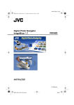
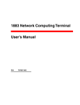
NETWORK CAMERA
Model:
IK-WB01A
IK-WB11A
Basic User's Guide
For information on the latest products and peripheral devices, refer to
the following Web page.
■ http://www.netcam.toshiba.com
The above URL is subject to change without prior notice. If the URL
changes, refer to theToshiba website
(http://www.netcam.toshiba.com).
If necessary, download “Advanced User's Guide” from above Toshiba website.
IK-WB11_01Cover
Page 1
03.8.4, 1:38 PM
Adobe PageMaker 6.5J/PPC
Introduction
Product Name : NETWORK CAMERA
Model Number(s) : IK-WB01A, IK-WB11A
FCC Notice "Declaration of Conformity Information"
Tested To Comply
With FCC Standards
FOR HOME OR OFFICE USE
Installation/Setup
This equipment has been tested and found to comply with the limits for a Class
B digital device, pursuant to part 15 of the FCC Rules. These limits are designed
to provide reasonable protection against harmful interference in a residential
installation. This equipment generates, uses and can radiate radio frequency
energy and, if not installed and used in accordance with the instructions, may
cause harmful interference to radio communications. However, there is no
guarantee that interference will not occur in a particular installation. If this
equipment does cause harmful interference to radio or television reception, which
can be determined by turning the equipment off and on, the user is encouraged
to try to correct the interference by one or more of the following measures:
Operation
- Reorient or relocate the receiving antenna.
- Increase the separation between the equipment and receiver.
- Connect the equipment into an outlet on a circuit different from that to which
the receiver is connected.
- Consult the dealer or an experienced radio/TV technician for help.
Warning : Changes or modifications made to this equipment, not expressly
approved by Toshiba or parties authorized by Toshiba could void the
user's authority to operate the equipment.
Others
This device complies with part 15 of the FCC Rules. Operation is subject to
the following two conditions :
(1) This device may not cause harmful interference, and
(2) this device must accept any interference received, including interference
that may cause undesired operation.
Toshiba America Information System, Inc.
Imaging Systems Division
9740 Irvine Boulevard,
Irvine, California 92618-1697
(800)288-1354
Industry Canada
This Class B digital apparatus complies with Canadian ICES-003.
2
IK-WB11_002~011
Page 2
03.8.4, 1:38 PM
Adobe PageMaker 6.5J/PPC
Introduction
Introduction
Thank you for purchasing the IK-WB01A/IK-WB11A Network Camera. Before
you start using the camera, read this User's Guide carefully to ensure correct
usage. Once you have finished reading this User's Guide, keep it in a convenient
place for future reference. The design, specifications, software, and User's Guide
contents are subject to change without prior notice.
IK-WB01A is designed for indoor-use only. You may use IK-WB11A either inside
or outside.
Terms and Trademarks
Installation/Setup
● The term "OS" is used in this manual to indicate operating systems
compatible with this product.
− Windows 98SE: Microsoft® Windows® 98 operating system; Second Edition
− Windows 2000: Microsoft® Windows® 2000 operating system
− Windows XP: Microsoft® Windows® XP operating system
● The formal name of Windows® is Microsoft® Windows® Operating System.
● Microsoft® and Windows® are trademarks or registered trademarks of
Microsoft® Corporation in the United States and other countries.
● Other product names appearing in this User's Guide may be trademarks or
registered trademarks of their respective holders.
Operation
● JavaTM and all Java-related logos and trademarks are trademarks or registered
trademarks of Sun Microsystems, Inc. in the United States and other
countries.
● Apple, Macintosh, iMac, Mac and Power Mac are registered trademarks of
Apple Computer, Inc.
● Netscape TM and Netscape TM Navigator are registered trademarks of
NetscapeTM Corporation.
● Ubiquitous TCP/IP-OS Copyright(c) 2002 Ubiquitous Corp.
Others
3
IK-WB11_002~011
Page 3
03.8.4, 1:38 PM
Adobe PageMaker 6.5J/PPC
Introduction (Cont.)
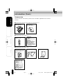
Accessories
Introduction
Confirm that all of the following accessories have been supplied with the network
camera.
● Accessories common to IK-WB01A and IK-WB11A
AC adaptor (x1)
Power cord (x1)
User's Guide (x1)
(this document)
Quick Start Guide (x1)
Installation/Setup
IK-WB01A
IK-WB11A
● Accessories for IK-WB01A
Screw set
・Self-tapping screw (x1)
(Black)
・Wood screws (x4)
(Silver)
Wire clamp (x1)
LAN cable (Straightthrough cable)(x1)
Clamp filter(x2)
※ Put the Clamp filter
to both ends of your
LAN cable.
Wall attachment for
indoor use (x1)
Operation
● Accessories for IK-WB11A
Others
Rear cover (waterproof cover
and attachment holder for indoor
and outdoor installation) with a
tripod screw hole (x1)
Sun visor (x1)
Wall bracket (x1)
Screw set
・M4 screws (x6)
(Silver)
・M3 screws (x4)
(Black)
・Self-tapping screw (x1)
(Black)
・Wood screws (x4)
(Silver)
LAN cable (Straightthrough cable)(x1)
Wire clamp (x1)
4
IK-WB11_002~011
Page 4
03.8.4, 1:38 PM
Adobe PageMaker 6.5J/PPC
Table of Contents
Introduction
Introduction
● Introduction ............................................................................................................... 3
● Table of Contents ................................................................................................... 5
● IMPORTANT SAFETY INSTRUCTIONS ............................................................ 6
● Precautions for Use ............................................................................................... 7
● About the AC adaptor ............................................................................................ 8
● Overview of the Network Camera ...................................................................... 9
● Features of the Camera ..................................................................................... 10
Installation/Setup
Installation / Setup
Operation
● Setting Up the Network Camera Environment .......................................... 12
● Requirements for Network Camera Monitoring System .............................. 12
● Namers of Camera Parts (IK-WB01A) ................................................................ 14
● Namers of Camera Parts (IK-WB11A) ................................................................ 15
● Installing the Camera (IK-WB01A) ................................................................. 16
● Installing the Camera (IK-WB11A) ................................................................. 18
● Indoor Installation ....................................................................................................... 18
● Outdoor Installation ................................................................................................... 19
● Connecting the Power Cord ............................................................................. 21
● Connecting the Camera and Personal Computer by Network ............. 23
・About the IP Address ........................................................................................... 23
● Using LAN Cable ........................................................................................................ 24
● Using Wireless LAN .................................................................................................. 25
・When Using Adhoc Method ............................................................................... 25
・When Using Infrastructure ................................................................................. 25
● About Wireless LAN Connection .................................................................. 27
・ Configuring the Wireless Network Environment for Camera's Wireless LAN settings...... 27
・ Configuring the camera's Wireless LAN settings for the Wireless Network Environment... 29
● Configuring Settings for Wireless LAN .............................................................. 31
● Using the Camera Search Application "Camera Finder" ......................... 34
● Configuring the Network Manually ................................................................. 36
● Log-in ID and Password ..................................................................................... 39
Others
Operation
● Administrator Operation .................................................................................... 42
● Administrator Login .................................................................................................. 42
● Screen Part Names and Functions ............................................................... 43
Others
● Setting Items ......................................................................................................... 48
・Camera Settings .................................................................................................... 48
・Network Settings ................................................................................................... 50
・Security Settings ................................................................................................... 54
・Multi-screen Mode Settings .............................................................................. 54
・Administrator Functions ...................................................................................... 55
・Log Management ................................................................................................... 56
● Specifications ........................................................................................................ 57
IK-WB11_002~011
Page 5
03.8.4, 1:38 PM
5
Adobe PageMaker 6.5J/PPC
IMPORTANT SAFETY INSTRUCTIONS
Introduction
When using this camera, always follow basic safety precautions to reduce the
risk of fire, electric shock,or personal injury.
Installation/Setup
1.
Read and understand all the instructions.
2,
Keep the User's Guide for future reference.
3.
Heed all warnings.
4.
Follow all the instructions.
5.
Wipe off any dust on the camera lens with a lens-cleaning cloth.
6.
Do not place the camera near any heat sources such as radiators, heat
registers, stoves, or other devices (including amplifiers) that produce heat.
7.
Protect the power cord from being steped on or pinched particularly at
plugs, convenience outlet, and the point where they exit from the unit.
8.
Use only specified attachments/accessories such as stands, tripods, and
brackets.
9.
Do not touch the camera or the AC adaptor during lightning storms.
10. Unplug the power cord when you do not use the camera for a long period of
time.
Operation
11. Refer all the services to qualified service personnel. Repairing is required
when the camera has been damaged in any way, such as :if power cord or
plug is damaged; the camera does not operate normally, the camera has
fallen to the ground.
Others
6
IK-WB11_002~011
Page 6
03.8.4, 1:38 PM
Adobe PageMaker 6.5J/PPC
Precautions for Use
About the SD Memory Card(IK-WB11A only)
Introduction
● There is a limit to the number of rewrites that is possible with the SD memory
card. Replacing of the SD memory card when performing periodic
maintenance of the camera is recommended.
Installation/Setup
● The camera supports the following SD memory cards. Do not use memory
cards with other specifications.
SD memory card:
8, 16, 32, 64, 128, 256, and 512 MB SD memory
cards (3.3 V) supported.
Physical interface: Part 1. Physical Layer Specification; Version 1.01
● Images may not be recorded or read correctly if an unsupported SD memory
card is used with the camera.
● Carefully read the User's guide, precautions on use, and any other information
supplied with a purchased memory card.
● An SD memory card can be used for the loop recording of images. The
lifespan (number of rewrites possible) of an SD memory card is greatly
affected by the capacity of the SD memory card. The use of a 128, 256, or
512 MB large-capacity SD memory card is recommended for loop recording.
Operation
● To achieve maximum performance of the camera, the use of a Toshiba SD
memory card is recommended. If a card of another company is used, the
recording intervals may lengthen and the erasure time during overwriting
may increase. As a result, the number of delivered frames of live video may
decrease.
● Do not use a memory card containing the data recorded by another device
with the camera as this may result in the camera not functioning correctly.
● Do not modify, overwrite the data, or change the folder name of an SD
memory card. It may result in the camera not to function correctly.
Others
● Data recorded with the camera do not comply with the image file format Exif
and the DCF standard. If the SD memory card is to be removed to play
images, use a personal computer to play the images. Other devices may
not be capable of displaying the images.
Caution for wireless mode
● During wireless mode operation, try to leave minimum of 20cm (8 inches)
spacing between people and the equipment.
7
IK-WB11_002~011
Page 7
03.8.4, 1:38 PM
Adobe PageMaker 6.5J/PPC
About the AC adaptor
Introduction
Be sure to use only the supplied AC adaptor. Using a different AC adaptor may
cause the camera to malfunction, heat up, or catch fire. Before using the AC
adaptor, carefully read and observe the Important Safety Instructions (→page
6) and the notes below.
●
Do not allow the connectors on the AC adaptor to come into contact with any
other metal object as this may result in short circuit.
●
To connect the AC adaptor, firmly insert the plug on the end of the cable into
the AC adaptor jack. Do not insert the plug into other jacks as this may cause a
malfunction.
When removing the connection cable, disconnect the cable by holding its plug.
Do not disconnect the cable by pulling on the cable.
Do not drop the AC adaptor or subject it to strong impact.
Do not use the AC adaptor in hot and humid places.
Do not use the supplied AC adaptor with devices other than this camera.
Temperature increasing on the surface of the adaptor is normal. Before moving
the adaptor to another location, unplug it from the wall outlet, and wait until its
temperature decreases.
Buzzing noises may come from inside. This does not indicate malfunction.
Using the AC adaptor near a radio, TV, or cellphone may cause interference.
Use the adaptor at sufficient distances from these devices.
Installation/Setup
●
●
●
●
●
●
●
Operation
Specifications
AC adaptor (AC-WB10)
Power supply
Rated output
Operating temperature
Storage temperature
External dimensions
:
:
:
:
:
100 to 240 V AC, 0.5 A, 50/60 Hz
10 V DC, 1.5 A
0℃ to +40℃
-20℃ to +65℃
50 x 32 x 85 mm (W / H / L)
Others
8
IK-WB11_002~011
Page 8
03.8.4, 1:38 PM
Adobe PageMaker 6.5J/PPC
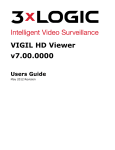
Overview of the Network Camera
Introduction
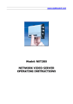
The IK-WB01A/IK-WB11A network camera can deliver video images and sound
in real time using the Internet or an intranet. The camera is equipped with
Ethernet (RJ-45) 10BASE-T/100BASE-TX and wireless LAN IEEE 802.11b
network interfaces.
IK-WB11A can be used in various indoor and outdoor environments.
IK-WB01A should be used indoors only.
Installation/Setup
Operation
IK-WB01A
IK-WB11A
Others
9
IK-WB11_002~011
Page 9
03.8.4, 1:38 PM
Adobe PageMaker 6.5J/PPC
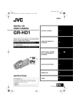
Features of the Camera
Introduction
Installation/Setup
Operation
Others
10
● Supports wireless LAN
The camera equips the wireless LAN IEEE 802.11b system. This enables
you to connect the camera and your computer without using a LAN cable.
● Built-in pan/tilt mechanism
A built-in pan (left/right) and tilt (up/down) mechanism enables you to use
the Internet browser to change the direction of the camera lens. The camera
also comes with Scan, Presets, Auto Patrol and various other monitoring
features.
● Equipped with 350K pixel Color CCD(IK-WB01A)
A 350K pixel, color CCD enables the delivery of images up to 640 x 480
dots.
● Equipped with megapixel CCD(IK-WB11A)
A 1.45 megapixel, progressive CCD enables the delivery of images up to
1280 X 960 dots. Images are delivered at high resolutions approaching
those of digital cameras.
● Supports multiple cameras
Toshiba's original protocol, RNCP, allows Toshiba network cameras to identify
each other on the same network. This enables images from automatically
identified network cameras to be displayed in multi-view screen in the same
browser window.
The number of windows in the multi-view display automatically changes (4
(2 x 2), 9(3 x 3) or 16(4 x 4) windows) accordingly to the number of identified
cameras.
The cameras on other networks can be displayed on the same multi-view
display screen by registering the cameras manually.
● Capable of delivering sound
The products deliver the sound input from an external microphone
(IK-WB11A) or built-in microphone (IK-WB01A) to you via the network.
● Mailing function
This feature allows you to receive mail messages with images when alarms
go off.
● Built-in SD memory card interface(IK-WB11A)
The use of SD memory cards enables the recording of images for long periods
of time, as well as recordings when alarms go off.
SD memory card:
8, 16, 32, 64, 128, 256, and 512 MB SD memory
cards (3.3 V) supported.
Physical interface: Part 1. Physical Layer Specification; Version 1.01
● Motion detection(IK-WB11A)
The camera incorporates the motion detector to generate an alarm.
● Privacy mask function(IK-WB11A)
This feature effectively maintains the privacy of delivered images. It allows
you to specify the masking areas in images.
● Equipped with a high-resolution, low F-stop lens(IK-WB11A)
The camera is equipped with a high-resolution, F1.4 high-quality lens for full
reproduction of images at a resolution of 1.45 megapixels.
● Waterproof camera that can be used outdoors(IK-WB11A)
A waterproof structure facilitates outdoor use. * 1
Waterproof specifications: IPX3 (Weather Resistant Rating)
* 1: Be sure to attach the Sun visor when installing the camera outside.
Install the camera where it will not be exposed to direct rain or sunlight.
Also, consult with the installation workers to ensure that the AC
adaptor, power cord, and LAN cable are installed with protection against
the weather in an outdoor location.
IK-WB11_002~011
Page 10
03.8.4, 1:38 PM
Adobe PageMaker 6.5J/PPC
Introduction
● High Sensitivity(IK-WB11A)
The camera accomplishes highly sensitive night-time monitoring by using a
slow-shutter speed (up to 4 seconds), Simple DAY/NIGHT function, and an
auto sensitivity boost function. ● Employs ND(Neutral Density)switching mechanism(IK-WB11A)
Outdoor and indoor location monitoring is made possible because of the ND
switching mechanism even though the camera has a fixed-iris lens.
Installation/Setup
Operation
Others
11
IK-WB11_002~011
Page 11
03.8.4, 1:38 PM
Adobe PageMaker 6.5J/PPC
Setting Up the Network Camera Environment
Requirements for Network Camera Monitoring System
Introduction
○ Administrator's personal computer
This camera cannot be used by itself. Be sure to connect the camera to a
personal computer and network. This User's Guide refers to a personal
computer that has been granted all privileges for configuring, operating,
monitoring, and other operations as the "administrator's personal computer."
System recommended requirements
・Windows® 2000/XP
Installation/Setup
・Internet ExplorerTM Ver. 6.0 or NetscapeTM Navigator 7.0
・CPU: Intel® Pentium® III 500 MHz or greater
・Memory: at least 256 MB
・Requires the installation of the freeware "JavaTM 2 Runtime
Environment SE ver.1.4.2" of Sun Microsystems, Inc. of the United
States. (The Version at present (July 2003))
※ If "JavaTM 2 Runtime Environment SE Ver.1.4.2" is not installed, this
product may not output images or sound properly.
※Access the following website to download "JavaTM 2 Runtime Environment
SE."
Operation
http://java.com
The URL may change without prior notice.
Downloading the setup file using dial-up communication is not
recommended because the setup file size exceeds 10 MB. It is
recommended to use broadband communication to download this file.
Others
※ JavaTM 2
This is the second generation of the JavaTM programming language
promoted by Sun Microsystems, Inc. of the United States. There are
improvements in performance, stability, security, and interoperability
compared with the previous generation.
※ This User's Guide refers to a personal computer that is used just for
monitoring images as a "user's personal computer." Multiple users' personal
computers can monitor images from a single network camera. For details,
refer to the Advanced User's Guide (See cover page).
○ Network camera (this product)
・ Purchase the required and appropriate number of cameras for the
installation location and the environment of the building or other location.
12
IK-WB11_012~022
Page 12
03.8.4, 1:38 PM
Adobe PageMaker 6.5J/PPC
Introduction
○ Appropriate connection devices (hub, router, etc.) and LAN cable for the
network system environment.
・ Not required if you are going to connect the personal computer and network
camera directly using a wireless LAN.
・ The type of LAN cable depends on the connection method used. For details,
refer to "Using LAN Cable" (→ page 24).
○ Select appropriate fixtures for the network system environment
Installation/Setup
・ Mounting the camera directly to the wall → Fix the camera in place with
the attachment (accessory)(IK-WB01A(→ page 16))(IK-WB11A(→ page
18))
○ Install the camera search application ("Camera Finder")
・ Download "Camera Finder" from <http://www.netcam.toshiba.com> , and then
install it. (→ page 34)
Operation
Others
13
IK-WB11_012~022
Page 13
03.8.4, 1:38 PM
Adobe PageMaker 6.5J/PPC
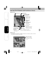
Setting up the Network Camera Enviroment (Cont.)
Introduction
Names of Camera Parts(IK-WB01A)
Front
Lens
(Focal range: 35 cm
to infinity)
Installation/Setup
Lens cover
(Transparent sphere)
Side
Bottom
Reset button (→ page 39)
Operation
・Reset the settings to the defaults by
using a thin, pointed object to press
the button for at least 5 seconds. (The
AC adaptor must be connected) (The log information is not returned to
the default state. To return the log
information to the default state, delete
the log information in the settings
screen.)
Holes for wall attachment (→ page 17)
Built-in microphone
(→ page 10)
Others
Rear
ALARM IN
Alarm input terminal
DC IN 10V
Power plug input terminal (→page 21)
・Be sure to use the AC adaptor included with the
network camera.
ALARM OUT
Alarm output terminal
GND
10/100 ETHERNET
Ethernet jack
14
IK-WB11_012~022
Page 14
03.8.4, 1:38 PM
Adobe PageMaker 6.5J/PPC
Introduction
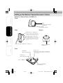
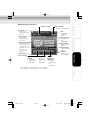
Names of Camera Parts (IK-WB11A)
Front
Sun visor (→ page 19)
(Accessory)
Lens
(Focal range: 80 cm
to infinity)
Installation/Setup
Lens cover
(Transparent sphere)
Reset button (→ page 39)
Side
Bottom
Operation
・Reset the settings to the defaults by using a
thin, pointed object to press the button for at
least 5 seconds. (The AC adaptor must be
connected) (The log information is not returned to the default
state. To return the log information to the default
state, delete the log information in the settings
screen.)
・You can turn video output on/off by pressing
the button for less than one second. When video
output is on, images and sound cannot be
delivered to the network and images cannot be
recorded. Use this feature only when, for
example, checking the angle of view during
installation.
SD memory card slot (→ page 7)
Rear cover fixing
screw (M3)
(→ page 19)
ALARM IN
Alarm input terminal
Screw hole for attaching
a tripod or other stand.
Others
Rear
Microphone input/Video output jack
・Jack for connecting an external microphone.
Use 3.5 φ monaural-plug microphone.
・Sound input from a microphone. video signal
can be simultaneously output if you use a stereo mini plug to mono dual jack conversion
adapter (commercially available product).
・Use the reset button to turn video output on/
off.
DC IN 10V
Power plug input terminal (→ page 21)
・Be sure to use the AC adaptor included with the network
camera.
ALARM OUT
Alarm output terminal
GND
10/100 ETHERNET
Ethernet jack
15
IK-WB11_012~022
Page 15
03.8.4, 1:38 PM
Adobe PageMaker 6.5J/PPC
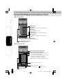
Installing the Camera (IK-WB01A)
Introduction
The IK-WB01A is for indoor use only. The following explains the installation
procedure.
Set the wall attachment to the wall
・Attach each of the four corners to the wall using four wood screws .
Installation/Setup
Operation
Important
●
Securely tighten the screws during installation to ensure not to become
loosen.
Connect the AC adaptor cable and the LAN cable
to the camera
Others
・For details, refer to "Connecting the Power Cord" (→ page 21) .
・If you are going to use a wireless LAN, you need to connect the AC
adaptor cable only.
16
IK-WB11_012~022
Page 16
03.8.4, 1:38 PM
Adobe PageMaker 6.5J/PPC
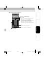
Front view
Rear view
Rear view
Front view
Rear view
Installation/Setup
Front
Front view
Introduction
Set the camera to the wall attachment
Operation
① Place the camera to the wall attachment at the angle shown in the
picture.
② Turn the camera counter-clockwise
・Make sure that the camera and wall attachment are properly fitting
together.
③ Push down the camera perpendicularly.
Important
●
●
Take care not to pinch the power cable and the LAN cable between the
camera and wall when attaching the camera to the wall attachment.
Secarely tighten the screwa during installation to ensure not to become
loosen.
Others
17
IK-WB11_012~022
Page 17
03.8.4, 1:38 PM
Adobe PageMaker 6.5J/PPC
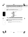
Installing the Camera (IK-WB11A)
Some provided parts are required for installing the camera.
Introduction
● Installing the camera indoors
・Rear cover
● Installing the camera outdoors
・Rear cover
・Cover for outdoor installation
■ Indoor Installation
Installation/Setup
Install the rear cover to the wall
・Install each of the four corners to the wall using four wood screws.
Operation
Important
●
Securely tighten the screws during installation to ensure not to become
loosen.
Others
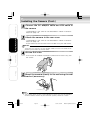
Insert the AC adaptor cable and the LAN cable
through the tube part of the rear cover
18
IK-WB11_012~022
・Insert both cables from below.
・If you are going to use a wireless LAN, you need to insert the AC
adaptor cable only.
Page 18
03.8.4, 1:38 PM
Adobe PageMaker 6.5J/PPC
Introduction
Connect the AC adaptor cable and the LAN cable
to the camera
・For details, refer to "Connecting the Power Cord" (→ page 21) .
・If you are going to use a wireless LAN, you need to connect the AC
adaptor cable only.
Installation/Setup
Install the camera to the rear cover
・Fix the camera to the rear cover from the sides using four M3 screws.
Operation
Important
●
Others
Take care not to trap the AC adaptor cable and LAN cable when attaching
the camera to the rear cover.
■ Outdoor Installation
Insert the AC adaptor cable and the LAN cable
through the tube part of the rear cover
・The procedure is the same as that described in "Indoor Installation"
Step 2 on page 18.
・Insert both cables from below.
・If you are going to use a wireless LAN, you need to insert the AC
adaptor cable only.
19
IK-WB11_012~022
Page 19
03.8.4, 1:38 PM
Adobe PageMaker 6.5J/PPC
Installing the Camera (Cont.)
Introduction
Connect the AC adaptor cable and LAN cable to
the camera
・The procedure is the same as that described in "Indoor Installation"
Step 3 on page 19.
Installation/Setup
Attach the camera to the rear cover
・The procedure is the same as that described in "Indoor Installation"
Step 4 on page 19.
・Fix the camera to the rear cover from the sides using four M3 screws.
Important
●
Take care not to pinch the AC adaptor cable and the LAN cable when
attaching the camera to the rear cover.
Set the Sun visor
Operation
・Fix the cover for outdoor installation in place from the rear using four
M4 screws.
Others
Mount the camera directly to the wall using the wall
bracket (accessory)
①
②
Provided M4 Screws
NOTE
●
The screws which attach the wall bracket and the wall are not provided.
Choose the best screws for your wall when you buy screws at a store.
20
IK-WB11_012~022
Page 20
03.8.4, 1:38 PM
Adobe PageMaker 6.5J/PPC
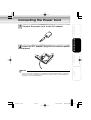
Connecting the Power Cord
Introduction
Connect the power cord to the AC adaptor
Installation/Setup
Insert the AC adaptor plug into the camera power
terminal
Operation
●
Others
Important
There is not much space around the opening of the power terminal, so make
sure that the plug is properly inserted. The camera may not work properly if
the plug is not inserted properly.
21
IK-WB11_012~022
Page 21
03.8.4, 1:38 PM
Adobe PageMaker 6.5J/PPC
Connecting the Power Cord (Cont.)
Introduction
As shown in the figure below, use a wire clamp to
fix the plug in place
・For the wire clamp, use the self-tapping screw supplied with the camera
to hold.
・When the plug is fixed in place, check that it will not become
disconnected by a moderate amount of pulling.
Installation/Setup
Turning on the Power
Operation
The camera has no main power switch or button. To turn the power on,
insert the plug of the power cord into a power outlet.
Turn the power on after you have installed the camera.
Others
NOTE
●
●
If you turn the power on without connecting the LAN cable, the network
camera starts in wireless LAN mode.
If you connect the LAN cable and then turn the power on, the network camera
starts in ordinary LAN mode.
22
IK-WB11_012~022
Page 22
03.8.4, 1:39 PM
Adobe PageMaker 6.5J/PPC
Connecting the Camera and Personal Computer by Network
■ About the IP Address
Introduction
To connect to the network, the administrator needs to set the network
camera IP address.
There are two options to set the IP address.
・ Obtaining an IP address automatically from the DHCP server
・ Entering an IP address manually (→ page 36)
●Obtaining an IP address automatically from the DHCP server
Installation/Setup
The "DHCP" setting is set to "ON" by default. This allows you to connect
to a network that uses a DHCP server without having to configure any
other settings.
Operation
Others
23
IK-WB11_023~030
Page 23
03.8.4, 1:39 PM
Adobe PageMaker 6.5J/PPC
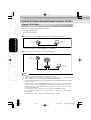
Connecting the Camera and Personal Computer by Network (Cont.)
Using LAN Cable
Introduction
The following shows two different network configurations using a LAN cable
connection to operate the network camera.
・Crossover connection
・Connection via a hub
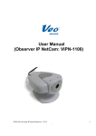
● Using a crossover cable to establish a connection (example)
Installation/Setup
Network camera
Personal computer
IP address
192.168.0.30
IP address
192.168.0.50
LAN cable (crossover)
Crossover cable is not provided with the product.
● Establishing a connection via a hub (example)
Network camera
Operation
IP address
192.168.0.30
Internet
Personal computer
Hub
IP address
192.168.0.50
LAN cable(straight through)
LAN cable(straight through)
Others
NOTE
You do not need to assign an IP address to a hub.
The IP address for the camera is specified to 192.168.0.30. Therefore, Set
the IP address for your computer to 192.168.0.50 here.
● There will be no problem to use the LAN port of your broadband router instead
of using a hub.
However, when using the broadband router, if the DHCP server function is
set "ON" and turn on the power after connecting the camera with the router,
the camera gets the IP address from the router's DHCP server and it may
not be 192.168.0.30.
For more information, read your user's guide for broadband router.
It is also reccomended to set the computer's IP address from the router's
DHCP server.
For more information, read your computer's user's guide.
●
●
24
IK-WB11_023~030
Page 24
03.8.4, 1:39 PM
Adobe PageMaker 6.5J/PPC
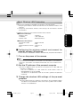
Using Wireless LAN
Introduction
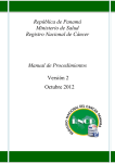
The followings show different network configurations using a wireless LAN
connection to operate the network camera.
■ When using adhoc method
The adhoc method is used for connecting the network camera and a personal
computer.
Installation/Setup
Personal computer
Network camera
IP address
192.168.0.30
IP address
192.168.0.50
(example IP address)
Adhoc method
Using a wireless LAN to establish a connection requires the following conditions.
1.Both the network camera and the personal computer are on the same network
segment.
2.Both the network camera and the personal computer use the same
communication channel.(→ page 32)
Operation
3.Both the network camera and the personal computer have the same ESS-ID
set.(→ page 32)
4.If WEP is used, both the network camera and the personal computer use
the same WEP encryption/key.(→ page 33)
■ When using infrastructure
Connect the network camera and a personal computer via an Access Point/
Wireless Broadband Router.
Personal computer
Others
Network camera
IP address
192.168.0.50
(example IP address)
IP address
192.168.0.30
Access Point/Wireless Broadband Router
Using an intranet requires the following condition.
・The default gateway is set correctly for the network camera if the
network camera will be accessed from different networks.
25
IK-WB11_023~030
Page 25
03.8.4, 1:39 PM
Adobe PageMaker 6.5J/PPC
Connecting the Camera and Personal Computer by Network (Cont.)
NOTE
Introduction
Installation/Setup
●
Information may be intercepted if you use a wireless LAN connection.
Improve security by using a WEP key. (→ page 33)
●
Communication using a wireless LAN connection is slower compared to
that of a wired connection, therefore less image frames can be
delivered.
●
If you use a wireless LAN connection, the effect of obstructions and
distance may result in slower communication speeds and the inability
to deliver images. If this is the case, you may be able to achieve slight
improvements by decreasing image and file sizes.
● Using port forwarding to publish images (example)
Personal computer
Broadband router
Internet
xDSL/CATV
xDSL/CATV
modem
Port forwarding
Operation
※Example IP addresses
Network camera(1) Network camera(2) Network camera(3)Network camera(4)
192.168.0.30
192.168.0.252
192.168.0.251
192.168.0.250
HTTP port; 80
HTTP port; 81
HTTP port; 82
HTTP port; 83
Using port forwarding to publish images requires the following condition.
・Ask your provider if it is possible to have port-forward connection.
Others
26
IK-WB11_023~030
Page 26
03.8.4, 1:39 PM
Adobe PageMaker 6.5J/PPC
About Wireless LAN Connection
Introduction
There are two methods to establish the wireless LAN connection.
1. Cofiguring the wireless network environment for the camera's wireless LAN
settings.
2. Cofiguring the camera's wireless LAN settings for the wireless network
environment.
● Wireless LAN settings
Connection mode
ESS-ID
Communication channel
WEP
:
:
:
:
Installation/Setup
The default settings of the network camera are as follows:
● Network information
Camera name
: nwcam01
IP address
: 192.168.0.30
Subnet mask
: 255.255.255.0
Adhoc method
ikwb
Channel 10
None
Operation
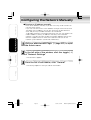
■ Configuring the wireless network environment for
camera's wireless LAN settings
Install a wireless LAN board or wireless LAN card into your personal computer.
1) Turn on the power of the camera
NOTE
●
Others
Ensure that the LAN cable is not inserted. If the LAN cable is inserted before
plugging in the camera, the network camera does not start in wireless LAN
mode.
2) Set the IP address of the personal computer
●
Set the IP address which you are not using other than 192.168.0.30
(camera's IP address).
・Set the IP address to 192.168.0.50 (and subnet mask to
255.255.255.0) as an example.
・ For details on the procedure, refer to the User's guide of the personal
computer.
3) Change the wireless LAN settings of the personal
computer
●
Set the same settings as "Wireless LAN settings" of the network camera.
・ For details on the procedure, refer to the User's guide of the installed
wireless LAN card/board.
27
IK-WB11_023~030
Page 27
03.8.4, 1:39 PM
Adobe PageMaker 6.5J/PPC
Connecting the Camera and Personal Computer by Network (Cont.)
Introduction
4) Make sure of the reply from the personal computer
to the network camera
Start a command prompt. Type as "ping 192.168.0.30" and press "Enter"
key.
● If the "Reply from..." message appears, the wireless connection is correctly
established.
・ If a message other than the above appears, reconfirm that the LAN
cable is not connected to another device and reconfirm the settings
configured in (2) and (3).
・ If you can still not ping the camera, connect the personal computer
and the camera with a LAN cable and then check the camera's network
settings to make sure that the wireless LAN settings are set as
described above.
・If there is still a problem, contact the Support Center (→ cover page).
●
Installation/Setup
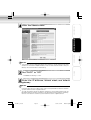
5) Try viewing camera images with "Camera Finder"
(→ page 34)
Operation
a) Start "Camera Finder" and click the "Search" button.
● Confirm that the camera name "nwcam01" and the IP address
"192.168.0.30" are displayed in the camera list.
● If they are not displayed, perform Step 3) again.
b) Click camera name to select.
● Confirm that the camera name and the IP address are displayed in red in
the network camera login field.
c) Click the "Administrator" button.
d) When the login screen appears, perform the administrator login (→ page
42).
● If the login screen is not displayed, select "Customize" from the "View
menu".
● In the Customize dialog box, check the Browser setting to see whether
a browser has been installed.
・The following shows the default setting.
C:\Program Files\Internet Explorer\IEXPLORER.EXE
e) When the "Admin Menu" screen is displayed, click the "LIVE" button.
● Images are displayed in single view.
● If images are not displayed, check whether JavaTM 2 is installed on the
personal computer.
● Install JavaTM 2 if it is not installed (→ page 12).
Others
NOTE
●
To view an image without using "Camera Finder", start the browser and
perform the administrator login (→page 42). Then click the "Live" button.
28
IK-WB11_023~030
Page 28
03.8.4, 1:39 PM
Adobe PageMaker 6.5J/PPC
Introduction
■ Configuring the camera's wireless LAN settings for
the wireless network environment
Beforehand, connect the LAN cable (straight cable) to a hub that has the
power turned on or connect the LAN cable (crossover cable) to a personal
computer that has the power turned on.
1) Plug in the camera
Installation/Setup
2) Set the IP address of the personal computer (→page
27)
3) Make sure of the reply from the personal computer
to the network camera (→ page 27)
4) Change the wireless LAN settings of the camera
Operation
a) Start the "Camera Finder" (→ page 34) and click the "Administrator"
button.
b) Click "Network Settings" → "Wireless LAN" in the "Admin Menu".
c) Configure the settings to match those of the wireless network
environment.
・ The communication mode is set to the adhoc method by default. If
you are going to view images via an access point or wireless
broadband router, be sure to change the communication mode to
infrastructure method.
d) Click the "Save" button.
e) Click the "Reboot" button.
NOTE
Others
●
To view an image without using "Camera Finder", start the browser and
perform the administrator login (→page 42). Then click the "Live" button.
5) Change the network information of the camera
a) Start the "Camera Finder" (→ page 34) and click the "Administrator"
button.
b) Click "Network Settings" → "General"
c) Configure the settings to match those of the wireless network
environment.
d) Click the "Save" button.
e) Click the "Reboot" button.
NOTE
●
To view an image without using "Camera Finder", start the browser and
perform the administrator login (→page 42). Then click the "Live" button.
29
IK-WB11_023~030
Page 29
03.8.4, 1:39 PM
Adobe PageMaker 6.5J/PPC
Connecting the Camera and Personal Computer by Network (Cont.)
6) Plug in the camera
Introduction
a) Confirm that the settings are the same as the wireless network
environment.
● When any settings are different from the wireless network
enviromment, set the same values.
b) Disconnect the LAN cable from the camera.
c) Unplug the camera once and plug it in again.
7) Confirm the camera connection
Installation/Setup
a) Ping the IP address set for the camera from a personal computer on
the network.
● Start a command prompt. Type as "ping XXX.XXX.X.XX (IP address
set for camera)" and press "Enter" key.
If the "Reply from..." message appears, the wireless connection is
correctly established.
・If a message other than the above appears: Start "Camera Finder" (→ page 34) and try performing a search.
NOTE
●
Operation
●
"Camera Finder" can find the camera even if the IP address of the camera
is incorrect (even if the wrong network address is specified).
Check whether the IP address of the camera found is the one set as your
network address.
・If "Camera Finder" was unable to find a camera, place the front of the
camera close to the antenna of the access point or wireless broadband
router and unplug the camera once and plug it again.
Others
30
IK-WB11_023~030
Page 30
03.8.4, 1:39 PM
Adobe PageMaker 6.5J/PPC
Configuring Settings for Wireless LAN
Introduction
To establish a wireless connection, it is necessary for the administrator to
configure the appropriate wireless LAN settings. The administrator also
needs to set the IP address. For details on setting the IP address, refer to
"About the IP Address" (→ page 23).
Installation/Setup
Perform administrator login (→ page 42) to open
the Admin menu
In the left side of the window, click the toggle (+)
of "Network Settings"
・The sub menus appear.
Operation
From the list of sub menus, click "Wireless LAN"
・The settings appear in the right side of the window.
Others
31
IK-WB11_031~038
Page 31
03.8.4, 1:39 PM
Adobe PageMaker 6.5J/PPC
Connecting the Camera and Personal Computer by Network (Cont.)
Introduction
Configure the communication mode
① Click ▼ for the "COM Mode" setting in the right side of the window.
② Select an item from the pull-down menu.
・If you are going to connect the network camera to the network via a
wireless broadband router or access point (AP), select
"infrastructure." If you are going to connect the network camera
directly to a personal computer, select "adhoc."
Installation/Setup
Configure the communication channel
①Click ▼ for the "COM Channel" setting in the right side of the window.
② Select an item from the pull-down menu.
・Channels 1 to 11 are available for use. If you are configuring the
network camera to work in an existing wireless LAN environment,
select the same channel.
NOTE
Operation
●
If you cannot establish a satisfactory wireless connection, try other channels
and select the channel that enables the optimal connection.
Enter the ESS-ID
・If you are connecting the network camera to an existing wireless LAN,
set the same ESS-ID as the existing wireless LAN environment. If you
are configuring a new wireless LAN, make sure that you do not set
the same ID as another existing wireless LAN.
Others
Important
●
There are restrictions on the values you can enter. You can only enter up to
32 alphanumeric characters.
NOTE
●
ESS-ID is sometimes simply expressed as SS-ID, SSID, or network group
name. In this manual, we use “ESS-ID.”This setting is an ID for identifying
the wireless group when multiple wireless LAN groups exist in the network
environment.
32
IK-WB11_031~038
Page 32
03.8.4, 1:39 PM
Adobe PageMaker 6.5J/PPC
Introduction
Configure the communication speed
①Click ▼ for the "COM Speed" setting in the right side of the window.
② Select an item from the pull-down menu.
・You can set "1.0," "2.0," "5.5," "11" Mbps, or "auto." It is
recommended to select "auto."
NOTE
Installation/Setup
●
This setting determines the speed of the network camera communicating
with other devices on the wireless LAN. The IEEE 802.11b standard
supports the communication speeds of 1.0, 2.0, 5.5, and 11 Mbps. However,
it is recommended to select "auto."
Configure the WEP key
① Click ▼ for the "WEP Key" setting in the right side of the window.
② Select an item from the pull-down menu.
Operation
・This setting determines the method used to encrypt data
transferred during wireless communication. Typically, 64-bit and
128-bit WEP keys are used. (128-bit WEP sets tighter security)
Sometimes "64-bit WEP" is described as "40-bit WEP", in here, we
use the term "64-bit WEP." This means that other wireless devices
using 40-bit WEP are using the same level of security as and are
compatible with devices that use 64-bit WEP.
Others
・You can select either of the two WEP keys or select not to use an
encryption key. If you are connecting the network camera to an
existing wireless LAN that uses a WEP key, set the same WEP
key to the network camera.
NOTE
●
There are rules for entering the WEP keys used for wireless data encryption.
Enter a 10-byte (hexadecimal digits) or 5-byte (ASCII text) character string
for the 64-bit WEP key, and a 26-byte (hexadecimal digits) or 13-byte (ASCII
text) character string for the 128-bit WEP key. When you use encryption
with the WEP key for the network camera, select the items for encryption
and WEP key correctly.
33
IK-WB11_031~038
Page 33
03.8.4, 1:39 PM
Adobe PageMaker 6.5J/PPC
Using the Camera Search Application "Camera Finder"
Introduction
The camera search application "Camera Finder" is an application for searching
network cameras, that can currently be viewed from the administrator's personal
computer or a user's personal computer, and connecting to those cameras.
You can use this application by downloading it from Toshiba website.
● Setting up "Camera Finder"
Installation/Setup
Access the following Toshiba Web page from the
Internet
URL:http://www.netcam.toshiba.com
Create a folder and download the application to the
folder
Operation
Download the application according to the explanation on the Web page.
Click the "Setup" file and install the "Camera Finder"
following the instruction on the screen
Others
● Using "Camera Finder" to Search for a Camera
From the Start menu, point to Programs and
TOSHIBA Network Camera, and then select Camera
Finder
Start up "Camera Finder" and click "Search"
・All the cameras currently connected to the network appear.
To clear the results, click "Clear".
34
IK-WB11_031~038
Page 34
03.8.4, 1:39 PM
Adobe PageMaker 6.5J/PPC
Introduction
Click the camera you want to login from the list of
cameras
・The chosen camera name and IP address is displayed in the Network
camera log-in fields.
To login as an administrator,
Installation/Setup
Click the "Administrator" button.
・For details on Adminstrator Login procedure, refer to page 42.
To login as a user,
Click the "User" button.
To close the window withont logging in
Click "Exit" to close "Camera Finder"
NOTE
Toshiba is not responsible for any damages caused by this software.
Operation
●
Others
35
IK-WB11_031~038
Page 35
03.8.4, 1:39 PM
Adobe PageMaker 6.5J/PPC
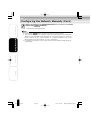
Configuring the Network Manually
● Entering an IP address manually
Introduction
・Enter an IP address manually if you are not using, or do not want to
use the DHCP server.
・If you use a DHCP server, the IP address changes from time to time.
Therefore, the IP address you set last time may not be valid next
time, and you may not able to access to the camera.
To be able to access the camera everytime you use, you need to set
fixed IP address (setting IP address manually) to the netwark
camera. If you do not know the pre-assigned IP address,consult the
relevant support center or refer to the relevant manuals of the
network system devices (router,hub, modem,etc.).
Installation/Setup
Perform administrator login (→ page 42) to open
the Admin menu.
In the left side of the window, click the toggle (+)
of "Network Settings"
Operation
・The sub menus appear.
From the list of sub menus, click "General"
・The settings appear in the right side of the window.
Others
36
IK-WB11_031~038
Page 36
03.8.4, 1:39 PM
Adobe PageMaker 6.5J/PPC
Introduction
Enter the camera name
Installation/Setup
Operation
Important
●
The camera name is displayed along with images in single view or multi view
screens. If there are multiple cameras, enter a name that will make it easy to
identify what the camera is monitoring.
Others
Set "DHCP" to "OFF"
・The default setting is "ON."
Enter the IP address, subnet mask, and default
gateway
Important
●
●
If you do not know the subnet mask, consult the provider or relevant network
system administration support center.
You do not need to enter the default gateway if the network camera will not
be accessed from another network. If you do need to enter a default gateway,
consult the relevant network system administration support center.
37
IK-WB11_031~038
Page 37
03.8.4, 1:39 PM
Adobe PageMaker 6.5J/PPC
Configuring the Network Manually (Cont.)
Introduction
Click the
save
button
・The settings are registered.
NOTE
●
●
Installation/Setup
●
Clicking the reset button restores the previous configuration.
The network camera has a feature (useful for multi view) that automatically
detects, and remember other cameras on the same network. If there are
other cameras on the same network, it is recommended to set "Auto
Identification of Other Cameras" to "ON" (→ page 50).
For details on configuring multi view, refer to "Multi-Screen Mode Settings"
(→ page 55).
Operation
Others
38
IK-WB11_031~038
Page 38
03.8.4, 1:39 PM
Adobe PageMaker 6.5J/PPC
Log-in ID and Password
Introduction
Be sure to change the default login ID and password. You are able to change
important information and settings of the camera through the Administrator
Login. To have higher security, be sure to change your login ID and the password,
and don't forget new login ID and password. Otherwise, you cannot access to
the camera. In the case you forget your login ID and password, press "Reset"
button (→ page 14, 15) for more than 5 seconds. It will return to the default
setting, but remember, in this case, all the information and settings will be
gone.
Installation/Setup
The default login ID is "root" and the default password is "ikwb".
With the Internet browser displayed on the
administrator's personal computer, enter the
following URL and press ENTER
http://192.168.0.30/admin.htm
If you enter this URL, the Administrator Login screen appears.
Operation
Others
Correctly enter the administrator login ID and the
password, and then click the "login" button
・"Admin Menu" screen appears.
39
IK-WB11_039~041
Page 39
03.8.4, 1:39 PM
Adobe PageMaker 6.5J/PPC
Log-in ID and Password (Cont.)
Introduction
In the Admin menu, click the toggle (+) of
"Administrator Functions"
・The sub menus appear.
Installation/Setup
Operation
Click "Changing the Password"
・The settings appear in the right side of the window.
Others
40
IK-WB11_039~041
Page 40
03.8.4, 1:39 PM
Adobe PageMaker 6.5J/PPC
Introduction
Enter the login ID and password in the "Current
Login ID", "Current Password", "New Login ID", "New
Password", and "New Password (Confirm)" fields.
Installation/Setup
Operation
Click the
save
button
・The new login ID and password are saved in the network camera.
Others
41
IK-WB11_039~041
Page 41
03.8.4, 1:39 PM
Adobe PageMaker 6.5J/PPC
Administrator Operation
Introduction
The viewing of images and operating of cameras are not restricted to the
administrator. The administrator can use all the functions. However, it is
necessary for the administrator to log in through the "Administrator Login"
screen, because an administrator who logs in from the "User Login" screen is
subject to the same restrictions as users.
How to view images and operate cameras is explained after the following
administrator login procedure explanation.
For details on "user login", refer to the Advanced User's Guide.
Installation/Setup
Administrator Login
You must enter the administrator's login ID and password first so that you can
be verified as an administrator on the network camera.
With the Internet browser displayed on the
administrator's personal computer, enter the
following URL and press ENTER
http://192.168.0.30/admin.htm
Operation
If you enter this URL, the "Administrator Login" screen appears.
Others
Correctly enter the administrator login ID and the
password, and then click the "login" button
・"Admin Menu" screen appears.
42
IK-WB11_042
Page 42
03.8.4, 1:39 PM
Adobe PageMaker 6.5J/PPC
Screen Part Names and Functions
● Admin Menu Screen
Introduction
Camera name
Live button
Displays images from the camera in single view.
Exit button
Installation/Setup
Closes the settings screen.
Do not use X button to close the setting screen.
Always use "Exit" button to close the setting screen
when you made any setting changes.
Operation
Main menus
Sub menus
Reset button
Save button
Saves the
changes.
Others
Restores the
previous
configuration.
43
IK-WB11_043~047
Page 43
03.8.4, 1:39 PM
Adobe PageMaker 6.5J/PPC
Screen Part Names and Functions (Cont.)
● Single View
Introduction
Camera name
Sound button
Switches sound on/off.
Multi View button
x1.0
Installation/Setup
Switches the
display to multi view.
The button is shown
only when the multi
viewfunction is set
"ON".
Controller button
Displays the
controller.
Image magnification
Indicates the
magnification
of camera images.
Time and date
Alarm Notification
Displays the current time
and date of the network
camera being accessed.
Operation
Displayed when
an alarm is detected.
SD memory card
(IK-WB11A)
Indicates SD memory
card is in use.
LIVE/PLAYBACK
LIVE:
Displaying live image
PLAYBACK: Displaying recorded image
● Multi View
All the buttons and icons, except the button for switching views, function
the same as those of single view.
Others
Single View button
Displays the upper
left screen in single
view.
44
IK-WB11_043~047
Page 44
03.8.4, 1:39 PM
Adobe PageMaker 6.5J/PPC
● Administrator Controller
Introduction
Camera name
Close button
Closes the controller.
Scan button
Moves the lens
horizontally back and
forth once.
1 shot
Captures one
image from
camera.
Auto Patrol button
Back Light button
Installation/Setup
Moves the lens
automatically at a
preset angle.。
Performs back
light
compensation.
Controller buttons
Zoom in button
Adjusts the direction
of the lens by panning
(left/right) and tilting
(up/down). The center
button moves the
lens to the center
position.
Enlarges camera
images.
Zoom out button
Reduces camera
image.
LIVE button
Preset
button
Alarm button
Displays
the Preset
controller.
Displays
the Alarm
list
controller.
Operation
Displays current
camera image.
Control buttons for
playing recordings
Record
button (IKWB11A)
Displays
the Record
list
controller.
※The network camera also has "User's controller".
For the details, see Advanced User's Guide.
Others
45
IK-WB11_043~047
Page 45
03.8.4, 1:39 PM
Adobe PageMaker 6.5J/PPC
Screen Part Names and Functions (Cont.)
● Preset controller
Introduction
Preset name
Installation/Setup
Go button
Moves the lens to the preset position.
Set button
Sets specified preset.
Clear button
Deletes settings of specified preset.
Name button
Changes the name of the specified
preset.
Operation
Preset Available/Unavailable Icon
Displays whether the preset is configured.
Preset Selection button
Specifies preset.
● Alarm list controller
Others
Time and date alarm generated
Alarm Recording Play button
Displays the images recorded at the time
the alarm was generated.
You can control the recorded images by
using "Control buttons for playing
recordings". For details, refer to the
Advanced User's Guide (See cover page).
Displays next 10 alarms.
Displays previous 10 alarms.
Alarm type ( : Motion Sensor (IK-WB11A), : External Alarm)
Alarm number
46
IK-WB11_043~047
Page 46
03.8.4, 1:39 PM
Adobe PageMaker 6.5J/PPC
● Record list controller (IK-WB11A)
Introduction
Time and date of recording
Play button
Installation/Setup
Displays the images recorded at a time
when there are no abnormalities.
You can control the recorded images by
using "control buttons for playing
recordings". For details, refer to the
Advanced User's Guide (See cover page).
Displays next 10 recordings.
Displays previous 10 recordings.
Operation
List number
Others
47
IK-WB11_043~047
Page 47
03.8.4, 1:39 PM
Adobe PageMaker 6.5J/PPC
Setting Items
Introduction
For more details on the settings, please refer to the Advanced User's
Guide at http://www.netcam.toshiba.com.
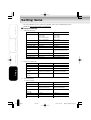
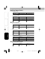
■ Camera Settings
1.General Settings
Item
IK-WB01A
IK-WB11A
Camera Picture Size
160
320
640
320
160
1280 x 960
800 x 600
640 x 480
320 x 240
160 x 120
Installation/Setup
x
x
x
x
x
120
240
480
240 ZOOM
120 ZOOM
Picture Quality
HIGH/MIDDLE/LOW
HIGH/MIDDLE/LOW
Frame Rate
HIGH/MIDDLE/LOW
HIGH/MIDDLE/LOW
Installation Environment Desktop/Wall, Ceiling
Desktop/Wall, Ceiling
AE Compensation
-20 to 20
-20 to 20
Auto B/W
ON/OFF
ON/OFF
Shutter Speed
ー
AES,1/120,1/60,1/30,
1/20,1/15,1/8,1/4,1/2,1,
2,4
Auto Slow Shutter※1
Operation
ー
ON/OFF
Auto Sensitivity Boost ー
ON/OFF
Sound Sensitivity
HIGH/MIDDLE/LOW
HIGH/LOW
※1: Auto-Slow shutter functions when the "shutter speed" is set "AES".
2.PAN/TILT Settings
Item
IK-WB01A
IK-WB11A
Others
P/T Operation Restrictions None/Administrator Only
None/Administrator Oniy
Auto Patrol Stopping Time 1, 2, 5, 10 minutes
1, 2, 5, 10 minutes
Scan Speed
SLOW/FAST
SLOW/FAST
Power Boost
CENTER, HOME,
CENTER, HOME,
Function
SCAN, AUTO PATROL
SCAN, AUTO PATROL
Freeze Activity
ON/OFF
ON/OFF
Item
IK-WB01A
IK-WB11A
Function
ON/OFF
ON/OFF
Input Type
Normal Closed (NC)/
Normal Closed (NC)/
Normal Opened (NO)
Normal Opened (NO)
OFF, Preset,Auto Patrol
OFF, Preset,Auto Patrol
Preset No.
1 to 10
1 to 10
Resume Function
ON/OFF
ON/OFF
Resume Time
10, 30, 60 seconds
10, 30, 60 seconds
Function
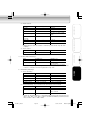
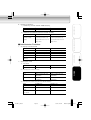
3.Alarm Settings
1)External Alarm
Associate to P/T
Operation
48
IK-WB11_048~057
Page 48
03.8.4, 1:40 PM
Adobe PageMaker 6.5J/PPC
2)Motion Sensor
IK-WB01A
IK-WB11A
Function
―
ON/OFF
Sensitivity
―
HIGH, MIDDLE, LOW
Size
―
Detection Range
―
LARGE, MEDIUM, SMALL
Set from screen ranges of 8X8
squares (See Advanced User's
Guide)
Associate to P/T
―
OFF, Preset, Auto Patrol
Preset No
―
1 to 10
Resume Function
―
ON/OFF
Resume Time
―
10, 30, 60 seconds
Introduction
Item
Installation/Setup
Operation
※ Depending on what the camera is monitoring, the sensor may not work
properly.
3)Alarm Output
Item
IK-WB01A
Output Hold Time
1, 5, 10, 15, 30, 60 seconds 1, 5, 10, 15, 30, 60 seconds
IK-WB11A
Operation
4.Privacy Mask Settings
Item
IK-WB01A
IK-WB11A
Function
―
Setup Range
―
ON/OFF
Set from screen ranges of
8 x 8 squares
(See Advanced User's Guide)
※ This is an easy image masking function. Depending on angles/movement of
PAN/TILT function, the masking positions may shift.
5.Recording Settings
Others
1)Alarm Recording
Item
IK-WB01A
IK-WB11A
External Alarm
ON/OFF
ON/OFF
Motion Sensor
―
ON/OFF
Pre-Recording
0, 3, 5, 10 frames
0, 3, 5, 10 frames
Post-Recording
0, 3, 5, 10, 20 frames
0, 3, 5, 10, 20 frames
Recording Cycle
1, 2, 5, 10 seconds
1, 2, 5, 10 seconds
2)Normal Recording (Only Possible when SD Memory Card Inserted)
Item
IK-WB01A
IK-WB11A
Function
―
ON/OFF
Recording Cycle
―
1*, 2, 5, 10, 30, 60, 120,
Timer Association
―
180 seconds
ON/OFF
* Iamge can be recorded with 1 second-recording cycle when picture sizes are
160 × 120, 320 × 240, 640 × 480: 2 seconds-recorded cycle when picture
sizes are 800 × 600, 1280 × 960.
49
IK-WB11_048~057
Page 49
03.8.4, 1:40 PM
Adobe PageMaker 6.5J/PPC
Setting Items (Cont.)
3)Timer Recording
Introduction
Item
IK-WB01A
IK-WB11A
Time Setting
―
Start: 0 to 23
Stop: 0 to 23
4)Overwriting
Item
IK-WB01A
IK-WB11A
Function
ー
ON/OFF
Installation/Setup
※ If you'd like to use this function, use SD memory card bigger than 128MB.
Otherwise, it may shorten the life of SD memory card.
※ When playing the recorded images from SD memory card, you cannot record any
images on the card.
※ If an SD memory card is used to record both alarm recordings and normal
recordings, thirty percent of the total storage space is used for alarm recordings
and the rest is used for normal recordings.
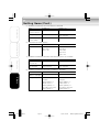
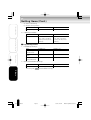
■ Network Settings
1.Network Connection Settings
1)General Settings
Operation
Item
IK-WB01A
Camera Name
Enter up to 32 single-byte Enter up to 32 single-byte
characters
Auto Identification of ON/OFF
IK-WB11A
characters
ON/OFF
Other Cameras
Others
DHCP
ON/OFF
ON/OFF
IP Address
Enter the static IP
Enter the static IP
address
address
Subnet Mask
Enter the subnet mask
Enter the subnet mask
Default Gateway
Enter the default gateway Enter the default gateway
2)DNS Settings
Item
IK-WB01A
IK-WB11A
Primary DNS Server
Enter the IP address
Enter the IP address
Enter the IP address
Enter the IP address
Item
IK-WB01A
IK-WB11A
HTTP Port No.
Enter the port number
Enter the port number
Item
IK-WB01A
IK-WB11A
Camera ID
Cannot be changed
Cannot be changed
IP Address
Secondary DNS
Server IP Address
3)HTTP Port Setting
4)Camera ID
50
IK-WB11_048~057
Page 50
03.8.4, 1:40 PM
Adobe PageMaker 6.5J/PPC
2.Wireless LAN Settings
IK-WB11A
Infrastructure, adhoc
Infrastructure, adhoc
COM Channel
1 to 11
1 to 11
ESS-ID
Enter up to 32 single-byte characters Enter up to 32 single-byte characters
COM Speed
Auto, 11, 5.5, 2.0, 1.0 Mbps Auto, 11, 5.5, 2.0, 1.0 Mbps
Encryption
Off, 64 bit WEP, 128 bit WEP Off, 64 bit WEP, 128 bit WEP
WEP Key Type
16 hexadecimal, ASCII text 16 hexadecimal, ASCII text
WEP Key
64 bit: 10 characters
(hexadecimal digits),
5 characters (ASCII text)
Installation/Setup
IK-WB01A
COM Mode
Introduction
Item
64 bit: 10 characters
(hexadecimal digits),
5 characters (ASCII text)
128 bit: 26 characters
128 bit: 26 characters
(hexadecimal digits),
(hexadecimal digits),
13 characters (ASCII text)
13 characters (ASCII text)
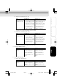
3.Mail Settings
1)Server Settings
IK-WB01A
IK-WB11A
SMTP Server Name
Enter the server name
Enter the server name
SMTP IP Address
Enter the IP address
Enter the IP address
POP3 Server Name
Enter the server name
Enter the server name
POP3 IP Address
Enter the IP address
Enter the IP address
Item
IK-WB01A
IK-WB11A
User ID
Enter the user ID
Enter the user ID
Password
Enter the password
Enter the password
Password (Confirm)
Reenter the password
Reenter the password
Operation
Item
2)Verification Settings
Others
3)Administrator Mail Settings
Item
IK-WB01A
IK-WB11A
Mail Address
Enter the mail address
Enter the mail address
Subject of Sent
Enter up to 128 single-
Enter up to 128 single-
Messages
byte characters
byte characters
4)Conditions for Sending Mail when An External Alarm Goes Off
Item
IK-WB01A
IK-WB11A
Send Mail When An
ON/OFF
ON/OFF
Enter up to 256 single-
Enter up to 256 single-
byte characters
byte characters
External Alarm Goes Off
Message Body
Attach Alarm Picture ON/OFF
ON/OFF
To Mail
51
IK-WB11_048~057
Page 51
03.8.4, 1:40 PM
Adobe PageMaker 6.5J/PPC
Setting Items (Cont.)
5)Conditions for Sending Mail When Motion is Detected
Introduction
Item
IK-WB01A
IK-WB11A
Conditions for Sending Mail
―
ON/OFF
Message Body
―
Enter up to 256 single-
Attach Motion
―
When Motion is Detected
byte characters
ON/OFF
Picture To Mail
Installation/Setup
6)Attached Picture Size Setting
Item
IK-WB01A
IK-WB11A
Attached Picture
640 x 480
1280 x 960
Size
320 x 240
800 x 600
160 x 120
640 x 480
320 x 240
160 x 120
7)Conditions for Sending Mail when Internal Battery Runs Out Of Power
Operation
Item
IK-WB01A
IK-WB11A
Send Mail When Internal
ON/OFF
ON/OFF
Out Of Power
Enter up to 256 single-
Enter up to 256 single-
Message Body
byte characters
byte characters
Battery Runs out
8)Conditions for Sending Mail When IP Address Is Changed
Item
IK-WB01A
IK-WB11A
Send Mail When IP
ON/OFF
ON/OFF
The IP address is
The IP address is
changed.
changed.
New IP address: ***
New IP address: ***
Subnet mask: ***
Subnet mask: ***
Default gateway: ***
Default gateway: ***
Day, month, year, time
Day, month, year, time
Camera Name; ***
Camera Name; ***
Address is Changed
Others
Message Body
52
IK-WB11_048~057
Page 52
03.8.4, 1:40 PM
Adobe PageMaker 6.5J/PPC
9)Addresses for Sending Mail(To)
IK-WB01A
Input fields for up to
・Enter the mail addresses
・Enter the mail addresses
10 addresses (To)
・For each address, you can
・For each address, you can
Introduction
Item
IK-WB11A
configure individually
whether mail is sent when:
whether mail is sent when:
an external alarm goes off,
an external alarm goes off,
the internal battery runs
the internal battery runs
out of power, or the IP
out of power, or the IP
address is changed
address is changed
Installation/Setup
configure individually
* There is a function for sending a test message.
10)Addresses for Sending Mail(Cc)
Item
IK-WB01A
IK-WB11A
Input fields for up to
・Enter mail addresses
・Enter mail addresses
10 addresses (Cc)
・For each address, you can
・For each address, you can
configure individually
whether mail is sent when:
whether mail is sent when:
an external alarm goes off,
an external alarm goes off,
the internal battery runs
the internal battery runs
out of power, or the IP
out of power, or the IP
address is changed
address is changed
Operation
configure individually
* There is a feature for sending a test message.
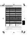
4.Routing Table Settings
IK-WB01A
IK-WB11A
Static Routing Table
Configure the following
Configure the following
Settings
settings for up to ten
settings for up to ten
entries: destination
entries: destination
address, subnet mask,
address, subnet mask,
gateway address, and
gateway address, and
metric
metric
Others
Item
5.ARP Table Settings
1)Static ARP Table Settings
Item
IK-WB01A
IK-WB11A
Static ARP Table
Configure the following
Configure the following
Settings
settings for up to ten
settings for up to ten
entries: IP address, MAC
entries: IP address, MAC
address
address
53
IK-WB11_048~057
Page 53
03.8.4, 1:40 PM
Adobe PageMaker 6.5J/PPC
Setting Items (Cont.)
2)Browse ARP Table
Introduction
Item
IK-WB01A
IK-WB11A
ARP Table
List of ARP displayed
List of ARP displayed
clear
* Clicking the
button deletes the contents of the ARP table.
6.DDNS Settings
Installation/Setup
Item
DDNS
DDNS User Name
DDNS Password
DDNS Server
IK-WB01A
ON/OFF
Enter the user name
Enter the password
Enter the server
name
IK-WB11A
ON/OFF
Enter the user name
Enter the password
Enter the server
name
■ Security Settings
1.Access Restriction Settings
Item
Restrict Access by
IK-WB01A
ON/OFF
IK-WB11A
ON/OFF
Enter up to ten IP
Enter up to ten IP
addresses
addresses
IK-WB01A
ON/OFF
IK-WB11A
ON/OFF
Enter up to ten MAC
Enter up to ten MAC
addresses
addresses
IP Address
Operation
IP Address
2.Filtering Settings
Item
Filtering by MAC
Address
MAC Address
Others
3.User Restriction Settings
Item
IK-WB01A
IK-WB11A
User Restrictions
ON/OFF
ON/OFF
Login ID
Enter the login ID
Enter the login ID
Password
Enter the password
Enter the password
Password (Confirm)
Reenter the password
Reenter the password
■ Multi-screen Mode Settings
1.Adding and Removing Cameras
Item
IK-WB01A
IK-WB11A
List of Registered
Enter the camera name
Enter the camera name
Cameras
and IP address
and IP address
54
IK-WB11_048~057
Page 54
03.8.4, 1:40 PM
Adobe PageMaker 6.5J/PPC
Item
IK-WB01A
IK-WB11A
Multi-Screen Mode
ON/OFF
ON/OFF
Introduction
2.Selecting Cameras
1)Switching to Multi-Screen Mode Setting
2)Selection of Cameras for Multi-screen Display
Item
IK-WB01A
IK-WB11A
Select cameras that were registered
for Multi-screen
by searching automatically or by
by searching automatically or by
Display
using the administrator function for
using the administrator function for
adding cameras
adding cameras
Installation/Setup
Selection of Cameras Select cameras that were registered
■ Administrator Functions
1.Changing the Password
IK-WB01A
IK-WB11A
Current Login ID
Enter the current login ID
Enter the current login ID
Current Password
Enter the current password Enter the current password
New Login ID
Enter the new login ID
Enter the new login ID
New Password
Enter the new password
Enter the new password
New Password
Reenter the password
Reenter the password
Item
IK-WB01A
IK-WB11A
Time Zone
GMT-12:00∼GMT+12:00 GMT-12:00∼GMT+12:00
Operation
Item
(Confirm)
2.Setting the Time
1)Time Zone
Item
IK-WB01A
IK-WB11A
Date
Select a date from the
Select a date from the
date boxes
date boxes
Select a time from the
Select a time from the
time boxes
time boxes
Time
Others
2)Changing the Time Manually
3)Changing the Time Using an NTP Server Setting
Item
IK-WB01A
IK-WB11A
Function
ON/OFF
ON/OFF
NTP Server Host
Enter the host name
Enter the host name
Enter the IP address
Enter the IP address
Name
IP Address for an
NTP Server
55
IK-WB11_048~057
Page 55
03.8.4, 1:40 PM
Adobe PageMaker 6.5J/PPC
Setting Items (Cont.)
4)Quick Time Setting
5)Daylight saving setting
Introduction
Item
IK-WB01A
IK-WB11A
Daylight saving
Valid, Invalid
Valid, Invalid
Item
IK-WB01A
IK-WB11A
File Path
Download the firmware.
Download the firmware.
Then, select the file by
Then, select the file by
entering the file path or
entering the file path or
browsing
browsing
Item
IK-WB01A
IK-WB11A
Forward Log to
ON/OFF
ON/OFF
Enter the server name
Enter the server name
Enter the IP address
Enter the IP address
3.Updating Firmware
Installation/Setup
■ Log Management
1.Forwarding Settings
Another Server
Name of Destination
Operation
Server
IP Address of
Destination Server
2.Browse and Delete Settings
Item
IK-WB01A
Log List
The list of logs is displayed The list of logs is displayed
* Clicking the
clear
IK-WB11A
button deletes the logs.
Others
56
IK-WB11_048~057
Page 56
03.8.4, 1:40 PM
Adobe PageMaker 6.5J/PPC
Specifications
Introduction
Model name
IK-WB01A
IK-WB11A
Image sensor
1/5-inch CCD
1/2-inch CCD
350k pixel
Effective Picture Element
1.45 megapixel
f=2.6mm
Focal length
f = 6.0 mm
。
。
。
。
。
。
Horizontal: 58 , vertical: 45 , diagonal: 70 Horizontal: 56 , vertical: 44 , diagonal: 67
Angle of view
Maximum relative aperture
F = 1.4
F = 2.8
AES, 1/120, 1/60, 1/30, 1/20, 1/15, 1/8, 1/4, 1/2, 1, 2, 4, sec.
Shutter speed
AES
1 lx (Normal, Auto-Sensitivity Boost OFF)
Minimum illumination
2 lx (Frame Rate HIGH)
0.03 lux (Slow shutter ON)
0.7lx (Frame Rete LOW)
。
。
。
112 (-56 to 56 )
Pan
。
。
。
54 (-49 to 5 )
Tilt
10 positions
Pan/tilt presets
Input ×1, Output ×1
Alarm terminal
1280×960 800×600
Image size
640×480 320×240 160×120
640×480 320×240 160×120
JPEG
Image compression method
3 levels
Quality settings
Max. 7.5 fps(640x480),
Max. 7.5 fps(1280x960, 800x600, 640x480),
Maximum frame rate
Max. 30 fps(320x240, 160x120)
Max. 15 fps(320x240zoom, 160x120zoom)
Available (buit-in microphone, PCM)
Available (MIC IN, PCM)
Audio *1
Unavailable
Available
Privacy mask feature
Unavailable
Available
Motion alarm feature
Normal recording feature
Unavailable
Available
External storage media
Unavailable
SD memory card
Video output
Unavailable
Available *2
Mail notification feature
Available
ND switching mechanism *3
None
Available
Interface
RJ-45 (10Base-T/100Base-TX), wireless LAN (IEEE802.11b)
TCP/IP, UDP/IP, HTTP, SMTP, DNS, DHCP, NTP, ARP, ICMP, syslog, DDNS
Protocols
10V DC
Power supply voltage
8W
Power consumption
Temperature: 0℃ to +40℃/
Operating ambient
Humidity: 80% or less
temperature/humidity
-20℃ to +60℃
Storage temperature
Weight
Approx. 600 g (camera only)
Approx. 650 g (camera only)
127 (W)×127 (H)×110 (D)mm (camera only)
External dimensions
AC adaptor (1), Power cord (1),
AC adaptor (1), Power cord (1), Rear cover
Accessories
Wall attachment (for indoor use) (1),
(waterproof cover and wall attachment
holder for indoor and outdoor installation)(1).
Clamp filter(x2)
Screw set, User's Guide,
Sun visor (for outdoor installation)(1),
Quick Start Guide,
Wall bracket(1), Screw set, User's Guide,
LAN cable (Straight-through cable)(1)
Quick Start Guide, LAN cable
(Straight-through cable)(1)
Installation/Setup
Operation
Others
*1: The sound may not be clear depending on the conditions of the lines.
*2: The image output is for checking the image during installation. Images
and sounds are not deliverd, and recording function will not work during
installation.
*3: The ND filter makes possible to monitor either outdoor or indoor location
by controlling light intensity.
●
Designes as specifications may change without prior notice for better
improvement.
57
IK-WB11_048~057
Page 57
03.8.4, 1:40 PM
Adobe PageMaker 6.5J/PPC
TOSHIBA AMERICA INFORMATION SYSTEMS. INC
Imaging System Division
9740 Irvine Boulevard,
Irvine California 92618-1697
PhoneNumber: (800)288-1354
IK-WB11_058~060
Page 58
03.8.4, 1:40 PM
V1.0
Adobe PageMaker 6.5J/PPC
59
IK-WB11_058~060
Page 59
03.8.4, 1:40 PM
Adobe PageMaker 6.5J/PPC
LIMITED WARRANTY
NETWORK CAMERA
The Imaging Systems Division of Toshiba America information Systems, Inc. ("ISD") makes the following limited warranties with
regard to this NETWORK Camera ("Product"). These limited warranties extend to the Original End-User ("You[r]").
One (1) Year Limited Warranty of Labor and Parts ISD warrants that this Product will perform in accordance with
specifications for a period of one (1) year from the date of purchase by Original End-User. During this one (1) year period, ISD
will repair or replace the Product, if it does not perform as warranted. In order to take advantage of this Limited Warranty, You
must: (a) deliver the Product to an ISD Authorized Service Provider ("ASP"): and (b) pay all transportation and insurance
charges for shipment of the Product to the ASP. ISD reserves the right to substitute factory refurbished parts in place of those
in need of repair.
User’s Guide (User's manual): You should read the User’s Guide (User's manual) thoroughly before operating this Product.
Before seeking warranty service, you should check the troubleshooting guide in the User's Guide (User’s manual) and follow
the instructions to correct the problem.
How to Obtain Warranty Service Step-by-step Procedures: To obtain warranty service, You should:
1. Contact Toshiba at (877) 855-1349 for operation or installation assistance. 877-MYNETCAM
2. Call 877-696-3822. A technical support specialist will help diagnose the problem. If the product requires a hardware repair,
Toshiba will refer an ASP who will repair or at Toshiba’s discretion, replace the product.
3. Arrange for shipment of the Product to a Toshiba Authorized Service Provider.
4. Securely pack the Product in the original carton and external shipping pack, include a letter explaining the problem with a
copy of the bill of sale or proof of purchase.
5. Prepay all transportation and insurance costs.
Questions? If you have any questions, please check our web site at http://www.netcam.toshiba.com
Your Responsibilities: This Limited Warranty is subject to the following conditions:
1. You must provide the bill of sale or proof of purchase at the time that warranty service is required.
2. You must notify an ASP within thirty (30) days after you discover that the product does not perform in accordance with
specifications during the Limited Warranty period.
3. All Warranty Service of this product must be by an ISD Authorized Service Provider.
4. You must pack the Product in its original carton using the original packing material. Then insert the original carton containing
the Product into another carton with additional packing material before shipping the Product to an ASP.
DISCLAIMERS:
ALL OTHER EXPRESS OR IMPLIED WARRANTIES ON THIS PRODUCT, INCLUDING THE IMPLIED WARRANTIES OF
MERCHANTABILITY AND FITNESS FOR A PARTICULAR PURPOSE, ARE HEREBY DISCLAIMED. SOME STATES DO
NOT ALLOW THE EXCLUSION OF IMPLIED WARRANTIES OR LIMITATIONS ON HOW LONG AN IMPLIED WARRANTY
LASTS. SO THE ABOVE LIMITATIONS MAY NOT APPLY TO YOU.
IF THIS PRODUCT IS NOT IN GOOD WORKING ORDER AS WARRANTED ABOVE, YOUR SOLE AND EXCLUSIVE
REMEDY SHALL BE THE REPAIR OF REPLACEMENT OF THE PRODUCT. IN NO EVENT WILL ISD OR ITS PARENT
COMPANY OR ANY ASP BE LIABLE TO YOU OR ANY THIRD PARTY FOR ANY DAMAGES IN EXCESS OF THE
PURCHASE PRICE OF THE PRODUCT. THIS LIMITATION APPLIES TO DAMAGES OF ANY KIND, INCLUDING ANY
DIRECT OR INDIRECT DAMAGES, LOST PROFITS, LOST SAVINGS OR OTHER SPECIAL, INCIDENTAL, EXEMPLARY
OR CONSEQUENTIAL DAMAGES, WHETHER FOR BREACH OF CONTRACT, TORT OR OTHERWISE, OR WHETHER
ARISING OUT OF THE USE OF OR INABILITY TO USE SUCH PRODUCT, EVEN IF TAIS, ITS PARENT COMPANY, OR AN
ASP HAS BEEN ADVISED OF THE POSSIBILITY OF SUCH DAMAGES OR OF ANY CLAIM BY ANY OTHER PARTY. SOME
STATES DO NOT ALLOW THE EXCLUSION OR LIMITATION OF INCIDENTAL OR CONSEQUENTIAL DAMAGES FOR
SOME PRODUCTS, SO THE ABOVE LIMITATIONS OR EXCLUSIONS MAY NOT APPLY TO YOU.
THIS WARRANTY GIVES YOU SPECIFIC LEGAL RIGHTS, AND YOU MAY ALSO HAVE OTHER RIGHTS WHICH MAY
VARY FROM STATE TO STATE.
THIS LIMITED WARRANTY SHALL BE VOID IF THE PRODUCT OR PARTS HAVE BEEN SUBJECTED TO MISUSE,
ABUSE, ACCIDENT, IMPROPER INSTALLATION, IMPROPER MAINTENANCE, OR USE IN VIOLATION OF ISD'S
WRITTEN INSTRUCTIONS, OR WHERE THE PRODUCT HAS BEEN ALTERED OR MODIFIED WITHOUT ISD'S PRIOR
AUTHORIZATION, OR UPON THE REMOVAL OR ALTERATION OF ISD'S FACTORY SERIAL NUMBER. LABOR SERVICE
CHARGES FOR PRODUCT INSTALLATION, SET UP AND ADJUSTMENT OF CONTROLS ARE NOT COVERED BY THIS
LIMITED WARRANTY.
No person, agent, distributor, dealer, authorized service provider, or company is authorized to change, modify, or extend the
terms of this Limited Warranty in any manner whatsoever. The time within which an action must be commenced to enforce any
obligation of ISD arising under this Limited Warranty or under any statute, or law of the United States or any state thereof, is
herby limited to three (1) years from the date You discovered the problem. This limitation does not apply to impelled warranties
arising under state law. Some states do not permit limitation of the time within which You may bring an action beyond the limits
provided by state law, so the above provision may not apply to You. This Limited Warranty gives You specific legal rights and
you may also have other rights which vary from state to state.
TOSHIBA AMERICA INFORMATION SYSTEMS, INC.
Imaging Systems Division
IK-WB11_058~060
Page 60
03.8.4, 1:40 PM
Adobe PageMaker 6.5J/PPC