1
comMQRPc@c”’’š“‹…ƒ™‹”“˜
s‡—›‹…‡@m”“‹™”—
o•‡—ƒ™‹”“@mƒ“šƒ‘
QPPRMPVPQMRpP
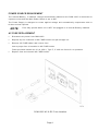
advancing wireless test
OPERATION MANUAL
COMMUNICATIONS SERVICE MONITOR
COM-120C
PU B L IS H ED B Y
IFR
CO P YR IGHT IF R 2 0 0 2
A l l r i g ht s r e s er v e d. N o p ar t of t h i s p ub l i c at i on ma y be r e pr o d u ce d , s tor e d i n a r etr i e va l s y s te m,
or tr an s m it t ed in an y f or m or b y a n y m e an s , el e ctr o n i c, m e c ha n i c a l, p h ot o co p y i ng , r e c o r d in g or
ot h er w i s e wi t ho ut t h e pr ior per m i s s io n o f th e p u bl i s h er .
10 2 00 W e st Y or k / W i c h it a, Ka n s a s 67 2 15 U . S. A . / ( 3 16 ) 52 2- 49 8 1 / F A X ( 3 1 6) 5 24- 2 62 3
CABLE STATEMENT
Double shielded and pr oper ly ter minated exter nal inter face cables must be used with this
equipment when inter facing with the RS- 232 and IEEE- 488.
For continued EMC compliance, all exter nal cables must be 3 meter s or less in length.
NOMENCLATURE STATEMENT
The CO M- 120C Communications Ser vice Monitor is the official nomenclatur e for the EMC and
Safety compliant CO M- 120C Communications Ser vice Monitor . In this manual the CO M- 120C
r efer s to the CO M- 120C Communications Ser vice Monitor . The gener ic ter ms unit and Test
Set also r efer to the CO M- 120C Communications Ser vice Monitor .
BATTERY STATEMENT
For continued EMC compliance with EN61000- 3- 2:1995/A14:2000, always allow a dischar ged
batter y to r echar ge in Stand- by Mode.
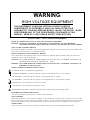
SAFETY FIRST: TO ALL OPERATIONS PERSO NNEL
REFER ALL SERVICING OF UNIT TO QUALIFIED TECHNICAL PERSONNEL. THIS UNIT CONTAINS NO
OPERATOR SERVICEABLE PARTS.
CASE, COVER OR PANEL REMOVAL
Removing protective covers, casings or panels from this unit exposes the operator to electrical hazards that
can result in electrical shock or equipment damage. Do not operate this unit with the case, cover or panels
removed.
SAFETY IDENTIFICATION IN TECHNICAL MANUAL
This manual uses the following terms to draw attention to possible safety hazards, that may exist when
operating or servicing this equipment.
CAUTION:
THIS TERM IDENTIFIES CONDITIONS OR ACTIVITIES THAT, IF IGNORED, CAN RESULT IN
EQUIPMENT OR PROPERTY DAMAGE (E.G., FIRE).
WARNING: THIS TERM IDENTIFIES CONDITIONS OR ACTIVITIES THAT, IF IGNORED, CAN RESULT IN
PERSONAL INJURY OR DEATH.
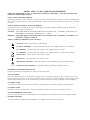
SAFETY SYMBOLS IN MANUALS AND ON UNITS
CAUTION: Refer to accompanying documents.
AC OR DC TERMINAL: Terminal that may supply or be supplied with ac or dc voltage.
DC TERMINAL: Terminal that may supply or be supplied with dc voltage.
AC TERMINAL: Terminal that may supply or be supplied with ac or alternating voltage.
SWITCH OFF: AC line power to the device is OFF.
SWITCH ON: AC line power to the device is ON.
DANGEROUS VOLTAGE: Indicates electrical shock hazard due to high voltage levels.
CAT II
INSTALLATION CATEGORY II: Denotes impulse withstand voltage of 2500 V.
EQUIPMENT GROUNDING PRECAUTION
Improper grounding of equipment can result in electrical shock.
USE OF PROBES
Check the specifications for the maximum voltage, current and power ratings of any connector on the unit
before connecting it with a probe from a terminal device. Be sure the terminal device performs within these
specifications before using it for measurement, to prevent electrical shock or damage to the equipment.
AC POWER CORD
AC power cord must not be frayed or broken nor expose bare wiring when operating this equipment.
DC POWER CORD
DC power cord is non-terminated. Care should be taken when connecting to external dc source.
USE RECOMMENDED FUSES ONLY
Use only fuses specifically recommended for the equipment at the specified current and voltage ratings.
INTERNAL BATTERY
This unit contains a Sealed Lead-Acid Battery, see Battery Instructions for servicing.
CAUTION:
SIGNAL GENERATORS CAN BE A SOURCE OF ELECTROMAGNETIC INTERFERENCE (EMI) TO
COMMUNICATION RECEIVERS. SOME TRANSMITTED SIGNALS CAN CAUSE DISRUPTION AND
INTERFERENCE TO COMMUNICATION SERVICES OUT TO A DISTANCE OF SEVERAL MILES.
USERS OF THIS EQUIPMENT SHOULD SCRUTINIZE ANY OPERATION THAT RESULTS IN
RADIATION OF A SIGNAL (DIRECTLY OR INDIRECTLY) AND SHOULD TAKE NECESSARY
PRECAUTIONS TO AVOID POTENTIAL COMMUNICATION INTERFERENCE PROBLEMS.
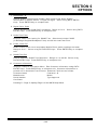
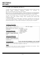
LIST OF EFFECTIVE PAGES
The manual pages list ed below t hat are af f ect ed by a current
change or revision, are so ident if ied by a revision number.
Dat e of Issue f or original and changed pages are:
O r iginal
........................... 0 .................... Feb
2002
TO TAL NUMBER O F PAG ES IN THIS MANUAL IS 326 CO NSISTING
O F THE FOLLOW I NG
Pg. No.
Rev. No.
Pg. No.
Rev. No.
6- 1 thr ough 6- 116 ....................
A- 1 thr ough A- 4 .......................
B- 1 thr ough B- 4 .......................
C- 1 thr ough C- 2 ......................
D- 1 thr ough D- 12 .....................
Index- 1 thr ough Index- 4 ...........
Batter y Title Page ....................
High Voltage War ning ..............
ESD Caution Page ...................
Page 1 thr ough Page 4 .............
Title and Copyr ight .................... 0
Cable Statement ....................... 0
Safety ...................................... 0
A thr ough B .............................. 0
i thr ough x ................................ 0
1- 1 thr ough 1- 24 ....................... 0
2- 1 thr ough 2- 4 ......................... 0
3- 1 thr ough 3- 28 ....................... 0
4- 1 thr ough 4- 72 ....................... 0
5- 1 thr ough 5- 30 ....................... 0
A
0
0
0
0
0
0
0
0
0
0
THIS PAGE INTENTIONALLY LEFT BLANK.
B
PREFACE
SCOPE
This manual contains instr uctions for oper ating the CO M- 120C Communications Ser vice
Monitor .
The instr uction level is r elatively basic and pr esupposes no pr evious
exper ience on the par t of the oper ator with a communication ser vice monitor of this
type. A basic under standing of communication electr onics and pr actical tr oubleshooting
methods is helpful. It is str ongly r ecommended that the oper ator be thor oughly familiar
with this manual befor e attempting to oper ate the unit.
ORGANIZATION
The CO M- 120C O per ation Manual is composed of the following sections:
SECTION 1 - INTRODUCTION
Pr ovides an intr oduction to the unit and a br ief over view of unit functions.
Specifications ar e also included in this section.
SECTIO N 2 - INSTALLATIO N
Pr ovides a step- by- step pr ocedur e for placing the CO M- 120C into oper ation.
SECTION 3 - CONTROLS, CONNECTORS AND INDICATORS
Identifies and functionally descr ibes all CO M- 120C contr ols, connector s and
indicator s.
All O per ation Scr eens and Menus ar e identified and available
par ameter s listed and explained.
SECTIO N 4 - O PERATIO N
Pr ovides instr uctions for oper ating the CO M- 120C Mode O per ating Scr eens and
Menus.
In addition, this section contains a selection of basic oper ating
pr ocedur es per taining to all major functions of the Test Set.
SECTIO N 5 - CO MMO N PRACTICES
Identifies and pr esents some examples of common pr actices the oper ator can use
to help become familiar with the CO M- 120C oper ation.
SECT IO N 6 - O PT IO N S
Identifies and pr ovides instr uctions for oper ating the options available with the
CO M- 120C.
i
TABLE OF CONTENTS
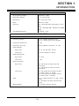
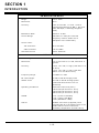
SECTION 1 - INTRODUCTION
Par agr aph
Title
Page
1- 1
G ener al .......................................................................................... 1- 1
1- 2
RF G ener ate O per ation .................................................................... 1- 2
1- 3
RF Receive O per ation ...................................................................... 1- 3
1- 4
Duplex O per ation ............................................................................ 1- 4
1- 5
Audio Function G ener ator s ............................................................... 1- 5
1- 6
O scilloscope ................................................................................... 1- 6
1- 7
Spectr um Analyzer .......................................................................... 1- 7
1- 8
Meter s ........................................................................................... 1- 9
1- 9
O ptions .......................................................................................... 1- 10
1- 10
CO M- 120C Pr oduct Specifications ..................................................... 1- 11
SECTION 2 - INSTALLATION
Par agr aph
Title
Page
2- 1
G ener al .......................................................................................... 2- 1
2- 2
Pr ecautions .................................................................................... 2- 1
2- 3
Power Up Pr ocedur es ...................................................................... 2- 3
2- 3- 1
Applying AC Power .......................................................................... 2- 3
2- 3- 2
Applying Exter nal DC Power ............................................................. 2- 3
2- 3- 3
Batter y Power O per ation ( O ption 01) ................................................. 2- 3
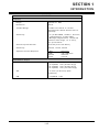
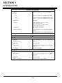
SECTION 3 - COMPOSITE
Par agr aph
Title
Page
3- 1
Fr ont Panel Contr ols ........................................................................ 3- 1
3- 2
Rear Panel Contr ols ........................................................................ 3- 7
3- 3
Scr eens, Soft Function Keys and Menus ............................................ 3- 9
ii
SECTION 3 – COMPOSITE (CONT)
Par agr aph
Title
Page
3- 3- 1
Soft Function Keys .......................................................................... 3- 9
3- 3- 2
Cur sor Movement ............................................................................ 3- 9
3- 3- 3
Editing Fields Using Data Scr oll Keys and Spinner .............................. 3- 9
3- 3- 4
Editing Numer ic Data Fields ............................................................. 3- 11
3- 3- 5
Making Selections Fr om Menus ......................................................... 3- 11
3- 3- 6
Escaping Fr om Edit Without Change .................................................. 3- 11
3- 3- 7
RF G ener ate Scr een ........................................................................ 3- 12
3- 3- 8
RF Receive Scr een .......................................................................... 3- 14
3- 3- 9
Duplex Scr een................................................................................. 3- 17
3- 3- 10
O scilloscope Scr een ........................................................................ 3- 20
3- 3- 11
Spectr um Analyzer Scr een ............................................................... 3- 22
3- 3- 12
Audio/Data/Signaling G ener ator s Scr een ........................................... 3- 24
3- 3- 13
Meter Scr eens ................................................................................. 3- 25
3- 3- 14
Memor y Lists and Stor age of Par ameter s ........................................... 3- 26
3- 3- 15
Utility Function Scr eens ................................................................... 3- 27
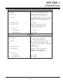
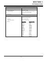
SECTION 4 - OPERATION
Par agr aph
Title
Page
4- 1
RF G ener ate O per ation .................................................................... 4- 1
4- 1- 1
G ener al RF G ener ate O per ation ........................................................ 4- 1
4- 1- 2
SINAD Meter O per ation .................................................................... 4- 13
4- 1- 3
Distor tion Meter O per ation ............................................................... 4- 16
4- 1- 4
Audio Fr equency Level Meter O per ation ............................................ 4- 18
4- 1- 5
O scilloscope O per ation Scr een ......................................................... 4- 20
4- 1- 6
Spectr um Analyzer O per ation Scr een ................................................ 4- 25
4- 1- 7
Stor e And Recall O per ation .............................................................. 4- 29
iii
SECTION 4 - OPERATION (CONT)
Par agr aph
Title
Page
4- 2
RF Receive O per ation ...................................................................... 4- 31
4- 2- 1
G ener al RF Receive O per ation ......................................................... 4- 31
4- 2- 2
SINAD Meter O per ation .................................................................... 4- 38
4- 2- 3
Distor tion Meter O per ation ............................................................... 4- 38
4- 2- 4
FM Deviation Meter O per ation .......................................................... 4- 39
4- 2- 5
AM Modulation Meter O per ation ........................................................ 4- 41
4- 2- 6
Phase Modulation Meter O per ation .................................................... 4- 43
4- 2- 7
RF Power Meter O per ation ............................................................... 4- 45
4- 2- 8
Received Level Meter O per ation ....................................................... 4- 47
4- 2- 9
RF Fr equency Er r or Meter O per ation ................................................. 4- 49
4- 2- 10
Audio Fr equency Counter ................................................................. 4- 51
4- 2- 11
O scilloscope O per ation Scr een ......................................................... 4- 53
4- 2- 12
Distor tion Meter .............................................................................. 4- 53
4- 2- 13
Stor e And Recall O per ation .............................................................. 4- 53
4- 3
Duplex O per ation ............................................................................ 4- 54
4- 3- 1
G ener al Duplex G ener ate O per ation .................................................. 4- 54
4- 3- 2
G ener al Duplex Receive O per ation .................................................... 4- 59
4- 4
Independent O scilloscope O per ation Scr een ...................................... 4- 62
4- 5
Independent Spectr um Analyzer O per ation Scr een .............................. 4- 62
4- 6
Independent Audio/Data/Signaling G ener ator s.................................... 4- 63
4- 6- 1
Audio G ener ator - 1 O per ation ............................................................ 4- 63
4- 6- 2
Audio G ener ator - 2 O per ation ............................................................ 4- 66
4- 6- 3
Data G ener ator O per ation ................................................................ 4- 67
4- 6- 4
DTMF G ener ator O per ation .............................................................. 4- 68
iv
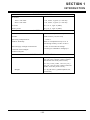
SECTION 4 - OPERATION (CONT)
Par agr aph
Title
Page
4- 7
Meter s O per ation ............................................................................. 4- 69
4- 7- 1
Digital Voltmeter O per ation .............................................................. 4- 69
SECTION 5 - COMMON PRACTICES
Par agr aph
Title
Page
5- 1
RF G ener ate ................................................................................... 5- 1
5- 1- 1
G ener ating FM Modulated RF Signal ................................................. 5- 2
5- 1- 2
G ener ating AM Modulated RF Signal ................................................. 5- 4
5- 1- 3
G ener ating PM Modulated RF Signal ................................................. 5- 6
5- 1- 4
G ener ating DCS Coded RF Signal ..................................................... 5- 8
5- 1- 5
G ener ating DTMF Coded RF Signal ................................................... 5- 10
5- 1- 6
G ener ating RF Signal Using Exter nal Modulation ................................ 5- 12
5- 1- 7
G ener ating Micr ophone Modulated RF Signal ..................................... 5- 14
5- 1- 8
Encoding 2- Tone Sequential For mat .................................................. 5- 16
5- 2
RF Receive ..................................................................................... 5- 19
5- 2- 1
Receiving FM Modulated RF Signal ................................................... 5- 20
5- 2- 2
Receiving AM Modulated RF Signal ................................................... 5- 22
5- 2- 3
Receiving PM Modulated RF Signal ................................................... 5- 24
5- 2- 4
Decoding 2- Tone Sequential For mat .................................................. 5- 26
5- 3
Duplex............................................................................................ 5- 28
v
SECTION 6 - OPTIONS
Par agr aph
Title
Page
6- 1
Inter nal Batter y ( O ption 01) .............................................................. 6- 1
6- 2
O ven Cr ystal O scillator Fr equency Standar d ( O ption 02) ..................... 6- 1
6- 3
30 kHz IF Filter ( O ption 03) .............................................................. 6- 1
6- 4
Var iable Audio G ener ator 2 ( O ption 04) ............................................. 6- 1
6- 5
G ener ate Amplifier ( O ption 05) ......................................................... 6- 1
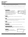
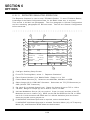
6- 6
Data G ener ator /Bit Er r or Rate ( BER) Meter ( O ption 07) ...................... 6- 2
6- 6- 1
BER Meter Configur ation Section ...................................................... 6- 4
6- 6- 2
Receive Data Configur ation Section .................................................. 6- 6
6- 6- 3
Send Data Configur ation Section ...................................................... 6- 8
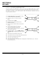
6- 7
Single Sideband Receive Filter ( O ption 08) ........................................ 6- 9
6- 7- 1
G ener al .......................................................................................... 6- 9
6- 7- 2
Descr iption of Receive Function ........................................................ 6- 9
6-8
RCC Signaling Formats (O ption 09)................................................... 6-10
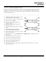
6- 9
Audio/Digital Signaling For mats ( O ption 11) ....................................... 6- 10
6- 9- 1
Modulating RF Signals with Digital Signaling For mats ......................... 6- 13
6- 9- 2
Encoding Digital Signaling For mats For Audio Signal .......................... 6- 15
6- 9- 3
Decoding Digital Signaling For mats ................................................... 6- 16
6- 9- 4
Testing A Receiver Using Digital Signaling For mats ............................ 6- 17
6- 9- 5
Testing A Tr ansmitter Using Digital Signaling For mats ........................ 6- 18
6- 10
Spectr um Analyzer Tr acking G ener ator ( O ption 12) ............................ 6- 19
6- 11
IEEE- 488 ( G PIB) Inter face ( O ption 13) .............................................. 6- 20
6- 11- 1
G ener al .......................................................................................... 6- 20
6- 11- 2
Configur ing For Remote O per ations Using G PIB ................................. 6- 20
6- 12
Clear channel LTR ( O ption 14) ........................................................ 6- 21
vi
SECTION 6 - OPTIONS (CONT)
Par agr aph
Title
Page
6- 12- 1
G ener al .......................................................................................... 6- 21
6- 12- 2
Accessing The Clear channel LTR Tr unking Test System ................... 6- 22
6- 12- 3
LTR Tr unking Repeater Simulation .................................................... 6- 23
6- 12- 4
Tr ansmit Tr unking Data Block ........................................................... 6- 27
6- 12- 5
Receive Tr unking Data Block ............................................................ 6- 28
6- 12- 6
LTR Tr unking Radio Simulation ......................................................... 6- 29
6- 12- 7
Tr ansmit Tr unking Data Block ........................................................... 6- 33
6- 12- 8
Receive Tr unking Data Block ............................................................ 6- 34
6- 12- 9
LTR Tr unking Auxiliar y Setup Scr een ................................................ 6- 35
6- 12- 10
Auxiliar y Setup Scr een Configur ation................................................. 6- 37
6- 12- 11
Repeater Simulator O per ation ........................................................... 6- 38
6- 12- 12
LTR Radio Handshake Test .............................................................. 6- 40
6- 12- 13
LTR Radio Handoff Test ................................................................... 6- 41
6- 12- 14
LTR Radio Receive Test ................................................................... 6- 42
6- 12- 15
Radio Simulator O per ation ............................................................... 6- 43
6- 12- 16
LTR Repeater Handshake Test ......................................................... 6- 45
6- 13
AMPS Cellular Testing ( O ption 15) .................................................... 6- 46
6- 13- 1
AMPS Cell Site Simulator Setup ........................................................ 6- 46
6- 13- 2
AMPS Cell Site Simulator Main and Setup Menus ............................... 6- 47
6- 13- 3
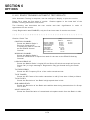
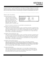
AMPS Cell Site Simulator Automatic Tests ......................................... 6- 52
6- 13- 4
Registr ation Test ............................................................................. 6- 53
6- 13- 5
Handoff Test ................................................................................... 6- 57
6- 13- 6
Audio Test ...................................................................................... 6- 58
6- 13- 7
Mobile Init Test ............................................................................... 6- 59
vii
SECTION 6 - OPTIONS (CONT)
Par agr aph
Title
Page
6- 13- 8
Cell Init Test ................................................................................... 6- 60
6- 13- 9
Automatic Test Pr intout .................................................................... 6- 61
6- 13- 10
AMPS Cell Site Simulator Manual Tests ............................................. 6- 62
6- 13- 11
Registr ation Test ............................................................................. 6- 63
6- 13- 12
Mobile Init Test ............................................................................... 6- 64
6- 13- 13
Cell Init Test ................................................................................... 6- 67
6- 14
EDACS Tr unking ( O ption 16) ............................................................ 6- 70
6- 14- 1
EDACS Tr unking Setup Scr een ......................................................... 6- 71
6- 14- 2
EDACS Tr unking Channel Assignments ............................................. 6- 72
6- 14- 3
EDACS Tr unking Automatic Test ....................................................... 6- 73
6- 14- 4
EDACS Tr unking Automatic Test Execution ........................................ 6- 74
6- 14- 5
EDACS Tr unking Automatic Test Results ........................................... 6- 76
6- 14- 6
EDACS Tr unking Manual Test ........................................................... 6- 82
6- 14- 7
EDACS Tr unking Manual Test- Repeater Simulator .............................. 6- 83
6- 14- 8
EDACS Tr unking Manual Test- Radio Simulator ................................... 6- 88
6- 14- 9
EDACS High- Speed Data Captur e ( Scope) ......................................... 6- 93
6- 14- 10
EDACS Stor e and Recall .................................................................. 6- 94
6- 14- 11
EDACS Tr unking O per ational Notes .................................................. 6- 95
6- 15
MPT 1327 Tr unking ( O ption 17) ........................................................ 6- 96
6- 15- 1
Setup Networ k Definition .................................................................. 6- 97
6- 15- 2
Syscode Calculation ........................................................................ 6- 99
6- 15- 3
Channel Number ing ......................................................................... 6- 100
6- 15- 4
Base Fr equencies ............................................................................ 6- 101
6- 15- 5
Tr unking Simulator Scr eens .............................................................. 6- 102
viii
SECTION 6 - OPTIONS (CONT)
Par agr aph
Title
Page
6- 15- 6
Repeater Simulator .......................................................................... 6- 104
6- 15- 7
Testing Radio Units ......................................................................... 6- 105
6- 15- 8
MPT 1327/ MPT 1343 Number ing Schemes ........................................ 6- 106
6- 15- 9
Radio Simulator ............................................................................... 6- 107
6- 15- 10
Automatic Test Mode, Test Selection ................................................. 6- 108
6- 15- 11
Par ametr ic Limits ............................................................................ 6- 110
6- 15- 12
Test Execution ................................................................................ 6- 112
6- 15- 13
Par ametr ic Results .......................................................................... 6- 113
6- 15- 14
O ff- Air Monitor ................................................................................ 6- 114
APPENDICES
Appendix
Title
Page
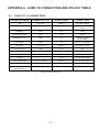
Appendix A
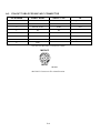
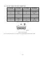
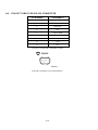
User I/O Connector s and Pin- O ut Table ............................................. A- 1
Appendix B
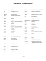
Abbr eviations .................................................................................. B- 1
Appendix C
Repacking For Shipping ................................................................... C- 1
Appendix D
Soft Function Keys .......................................................................... D- 1
INDEX
BATTERY/ VOLTAGE/ FUSE INSTRUCTIONS
Title
Page
Power Sour ce Requir ement ................................................................................ Page- 1
AC Fuse Replacement ....................................................................................... Page- 1
DC Fuse Replacement ....................................................................................... Page- 2
Batter y Replacement ......................................................................................... Page- 2
Batter y Fuse Replacement ................................................................................. Page- 4
ix
THIS PAGE INTENTIONALLY LEFT BLANK.
x
SECTION 1
INTRODUCTION
1-1
GENERAL
The CO M- 120C is a micr opr ocessor contr olled, digitally synthesized communication
ser vice monitor , which combines the oper ations of many differ ent test instr uments into a
single, compact unit. The CO M- 120C is capable of per for ming these functions:
RF Generator
RF Receiver
Full Duplex Operation
Spectrum Analyzer
Audio/Data/Signaling
Generators
O sci l l o sco p e
DVM
Deviation Meter
Distortion Meter
SINAD Meter
Audio Frequency Meter
F r e q u e n cy E r r o r M e t e r
RF Power Meter
Modulation Meter
R e ce i ve d L e ve l M e t e r
The CO M- 120C utilizes an alphanumer ic keypad, dedicated function keys, multitask
“ Soft” Function Keys and a high r esolution, monochr ome flat panel display. Per for m
tests r emotely or manually.
Micr opr ocessor contr olled memor y allows par ameter
stor age and r ecall. For instance, stor e and r ecall O scilloscope and Spectr um Analyzer
tr aces for signal compar ison.
The CO M- 120C per for ms a multitude of impor tant functions simultanelusly. The thr ee
basic modes of oper ation ar e: RF G ener ate O per ation, RF Receive O per ation and
Duplex O per ation. These modes allow gener ate and r eceive functions in duplex and
simplex mode, while testing other aspects of the Unit Under T est like Modulation Level,
Power , Sensitivity and Fr equency Er r or .
Additionally, the CO M- 120C pr ovides these independent test instr uments:
Audio/Data/Signaling Generators
O sci l l o sco p e
S p e c t r u m A n a l yze r
Meters
1-1
SECTION 1
INTRODUCTION
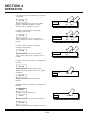
1-2
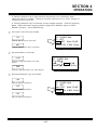
RF GENERATE OPERATION
Generating
The CO M- 120C is capable of gener ating CW or modulated signals fr om 250 kHz to
1000 MHz.
The output level is var iable fr om - 130 to - 13 dBm.
Modulation types include AM, FM and PM ( Phase Modulation) or apply an exter nal
modulation sour ce. G ener ate DTMF, User Defined Tone Codes or Digital Codes.
Meters
Meter ing functions include SINAD, Distor tion and Audio Fr equency Level.
Full O scilloscope and Spectr um Analyzer oper ation is available.
Testing
Testing in RF G ener ate O per ation includes Receiver Sensitivity, Receiver Selectivity,
and Audio Fr equency Level measur ements.
n OTe
Use the decode capability for defined DCS and POCSAG
protocols using the Tone and Digital Coding functions.
1-2
SECTION 1
INTRODUCTION
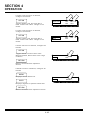
1-3
RF RECEIVE OPERATION
Receiving
The CO M- 120C r eceives CW and modulated signals r anging fr om 250 kHz to 1000 MHz.
In addition to single fr equency oper ation, the CO M- 120C demodulates and detects AM,
FM and PM modulated signals and executes defined fr equency sweep oper ations by
scanning a r ange of pr edeter mined Fr equency List settings.
The CO M- 120C r eceives “ off- the- air ” signals via the Antenna Connector or connects
dir ectly to the Unit Under Test via the T/R Connector .
Meters
Receive O per ation Meter ing functions include RF Power , AM Modulation, FM Deviation,
Phase Modulation, Distor tion, Fr equency Er r or , AF Fr equency, Received Level and
SINAD.
Full O scilloscope and Spectr um Analyzer oper ation is available.
Testing
Testing in RF Receive O per ation includes measur ing Car r ier Power , Modulation,
Distor tion, SINAD and RF Fr equency Er r or .
n OTe
Use the independent Audio/Data/Signaling Generators to
modulate the Unit Under Test when performing RF Receive
Operation.
1-3
SECTION 1
INTRODUCTION
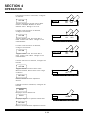
1-4
DUPLEX OPERATION
The CO M- 120C Duplex O per ation featur e r anges fr om 250 kHz to 1000 MHz.
The RF G ener ator and RF Receiver both wor k in Duplex O per ation Mode with the added
capacity of using offset fr equencies up to ± 999.7500 MHz. Testing capabilities mir r or
those found in RF G ener ate and RF Receive O per ations.
Duplex O per ation is composed of thr ee O per ation Scr eens.
Ú The Duplex
information.
Operation
Screen
contains
both
Receive
and
Generate
Ú The Duplex Receive Operation Screen is provided to test the Transmit
section of the Unit Under Test.
Ú The Duplex Generate Operation Screen is provided to test the Receive
section of the Unit Under Test.
1-4
SECTION 1
INTRODUCTION
1-5
AUDIO FUNCTION GENERATORS
Audio/Tone Coding
The CO M- 120C has two Audio G ener ator s. O ne gener ator has a r ange of 10 Hz thr ough
20 kHz and the second gener ator has a fixed 1 kHz tone. The wavefor ms ar e sine,
squar e, tr iangle and r amp.
DATA
The DATA G ener ator gener ates in DCS, DCS Inver ted, PO CSAG and PO CSAG Inver ted
for mats.
DTMF
The DTMF G ener ator gener ates DTMF coding, up to 16 char acter s long, in Bur st,
Continuous Mode or configur es the DATA ENTRY Keypad as a DTMF Keypad. The
DTMF Mar k and Space timing and the time between str ing tr ansmissions ar e
pr ogr ammable.
1-5
SECTION 1
INTRODUCTION
1-6
OSCILLOSCOPE
The CO M- 120C has a 50 kHz single tr ace O scilloscope. The O scilloscope can oper ate
as a dependent or independent function in each of the O per ation Modes. Both functions
give the choice of oper ation modes, live, stor e, r ecall, compar e and aver age. The
Tr igger type choices ar e Nor malized, Auto and O ne Shot.
Dependent
The dependent O scilloscope is available with meter s and shar es space in all O per ation
Modes with the dependent Spectr um Analyzer .
In G ener ate O per ation, sour ces
available for the O scilloscope ar e thr ough fr ont panel input connector s, Notch Filter
Residual and inter nal modulation sour ces. In Receive O per ation, sour ces available for
the O scilloscope ar e thr ough the fr ont panel input connector s, Audio/Data/Signaling
G ener ator s, decode lines, meter lines and the demodulated signal, both filter ed and
unfilter ed. Sweep and scale values differ with each input type.
Independent
The independent O scilloscope only accepts signals fr om the SCO PE/DVM Connector .
The coupling choices ar e AC, DC and G r ound.
1-6
SECTION 1
INTRODUCTION
1-7
SPECTRUM ANALYZER
The Spectr um Analyzer monitor s inter nal and exter nal signals r anging fr om 250 kHz to
1000 MHz. The Scan width r ange is editable fr om 1 kHz to 100 MHz per /div. The
Sweep r ate and Resolution Band Width ( RBW) ar e editable with a menu or manual edit.
An UNCAL indication appears on the scr een when settings cause an analyzer “uncal”
situation.
The log scales ar e 2 and 10 dB per division. Amplitude scale units of dBm, dBµV,
dBmV, dBV, dBµW and dBW ar e available in the Independent Spectr um Analyzer and
with the Receive O per ation. T he G ener ate Spectr um Analyzer is a r elative measur ing
device only. Available units ar e limited to dB.
Memor y functions for the Spectr um Analyzer include stor e and r ecall of a tr ace,
compar e a stor ed tr ace to a live tr ace and peak hold. The Slot number is editable.
Exter nal signals can be “ off the air ” thr ough the Antenna Connector or connected
dir ectly to the T/R Connector .
The Independent and Receive Function Spectr um Analyzer have attenuation of 0 and
30 dB thr ough both connector s. The Spectr um Analyzer is available for display alone or
with all RF G ener ate and Receive functions except wher e the Duplex Tr ansmit and
Receive functions ar e shown simultaneously.
1-7
SECTION 1
INTRODUCTION
Generate Operation
The G ener ate O per ation Spectr um Analyzer is a r elative measur ing device only and
available units ar e limited to dB. Scan widths r ange fr om 1 kHz to 100 MHz per /div and
zer o scan. Available log scales ar e 2 and 10 dB per division. Memor y functions for the
Spectr um Analyzer include stor e and r ecall of a tr ace, compar e a stor ed tr ace to a live
tr ace and peak hold.
Receive Operation
The Receive O per ation Spectr um Analyzer r eceives signals r anging fr om 250 kHz to
1000 MHz. Scan widths r ange fr om 1 kHz to 100 MHz per /div and zer o scan. Available
log scales ar e 2 and 10 dB per division. Amplitude scale units ar e dBm, dBµV, dBmV,
dBV, dBµW and dBW. Memor y functions for the Spectr um Analyzer include stor e and
r ecall of a tr ace, compar e a stor ed tr ace to a live tr ace and peak hold. Input signals
can be “ off the air ” thr ough the Antenna Connector or connected dir ectly to the T/R
Connector . The Spectr um Analyzer has 0 and 30 dB attenuation available thr ough both
connector s.
Independent
The Independent Spectr um Analyzer r eceives signals r anging fr om 250 kHz to 1000
MHz. Scan widths r ange fr om 1 kHz to 100 MHz per /div and zer o scan. The log scales
ar e 2 and 10 dB per division. Amplitude scale units ar e dBm, dBµV, dBmV, dBV, dBµW
and dBW ar e available. Memor y functions for the Spectr um Analyzer include stor e and
r ecall of a tr ace, compar e a stor ed tr ace to a live tr ace and peak hold.
Input signals can be “ off the air ” thr ough the Antenna Connector or connected dir ectly to
the T/R Connector . The Spectr um Analyzer has 0 and 30 dB attenuation available
thr ough both connector s. Additional Functions available with the Independent Spectr um
Analyzer include a Find function for finding signals above a cer tain level and split
scr een displaying two Spectr um Analyzer scr eens.
1-8
SECTION 1
INTRODUCTION
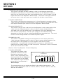
1-8
METERS
Dependent
The CO M- 120C pr ovides meter ing capability in all thr ee O per ation Modes. The meter s
ar e in Receive O per ation, G ener ate O per ation or both. The meter s ar e available for
Simplex and Duplex O per ation. The meter s ar e r epr esented dir ectly on the Mode
O per ation Scr een as numer ic r eadout or as a bar meter and numer ic r eadout. Although
a meter is available in both Receive and G ener ate O per ation, available inputs may
differ . Dependent Meter s for each O per ation Mode ar e identified below:
RECEIVE OPERATION
GENERATE OPERATION
SINAD
SINAD
F M D e vi a t i o n
D i st o r t i o n
P h a se M o d u l a t i o n
Audio Level
R e ce i ve d L e ve l
Audio Counter
Independent
The CO M- 120C pr ovides meter ing capability independent of the O per ation Modes.
These meter s include:
SINAD
Audio Counter
Distortion
Digital Voltmeter
1-9
SECTION 1
INTRODUCTION
1-9
OPTIONS
Option 01 – Internal Battery
Provides self-contained dc power when
external ac or dc power is unavailable.
Option 02 – 0.01 OCXO
R e p l a c e s t h e s t a n d a r d T C X O a s syst e m
6
t i m e b a s e . P r o v i d e s 0 . 0 1 x 1 0 a ccu r a cy.
Option 03 – 30 kHz IF Filter
This option provides additional band
limiting between 15 kHz and 300 kHz
offered in a standard set.
Option 04 – Variable Audio Generator 2
Replaces standard fixed 1 kHz Audio
Generator with variable frequency Audio
Generator.
Option 05 – Generate Amplifier
Internal RF Amplifier providing 26 dB
gain for additional RF output.
Option 07 – Data Generator/Bit Error
Rate (BER) Meter
This option provides testing for digital
ch a r a ct e r i st i cs o f t r a n sce i ve r s.
Option 08 – SSB Receive Filter
This option provides ability to monitor
S S B si g n a l s.
Option 09 – RCC Signaling
T h i s o p t i o n p r o vi d e s 1 0 P S , 2 0 P S , M T S ,
IMTS and Tone Remote Control
signaling.
Option 11 – Audio/Digital Signaling
This option provides encode/ decode
ca p a b i l i t i e s f o r t h e f o r m a t s: C C I R ,
CCIRH, CCIRH4, EEA, EIA, NATEL,
ZVEI, DZVEI, DDZVEI, EURO, 5/6 Tone
and POCSAG.
Option 12 - Tracking Generator
This option provides internal Tracking
G e n e r a t o r f o r u se w i t h S p e ct r u m
A n a l yze r .
Option 13 - IEEE 488 (GPIB) Interface
This option provides parallel GPIB
i n t e r f a ce f o r r e m o t e o p e r a t i o n .
Option 14 - CLEARCHANNEL LTR
Simulates the CLEARCHANNEL LTR
repeater system. CLEARCHANNEL LTR
i s a R e g i st e r e d T r a d e m a r k o f E . F .
Johnson.
Option 15 - AMPS Mobile Station Test
Auto and manual test to verify operation
o f A M P S m o b i l e s, t r a n sp o r t a b l e s a n d
portables.
Option 16 - EDACS
P r o vi d e s t e st ca p a b i l i t y f o r E D A C S
repeaters and mobiles
1-10
SECTION 1
INTRODUCTION
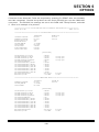
1-10
COM-120C PRODUCT SPECIFICATIONS
A war m- up time of 5 minutes is r equir ed for the following per for mance r equir ements.
RF measur ements ar e r efer enced to 50 Ω .
Accur acy and Resolution stated in per cent ar e r efer enced to measur ed or selected value
unless other wise stated.
Wher e r esolution exceeds accur acy, r esolution takes pr ecedence.
Specifications and featur es ar e subject to change without notice.
RF SIGNAL GENERATOR
F r e q u e n cy
Range:
250 kHz to 1 GHz
Resolution:
100 Hz
Accuracy:
S a m e a s M a st e r O sci l l a t o r .
O u t p u t ( T / R a n d A U X R F C o n n e c t o r s)
Range (T/R):
-130 to -20 dBm (Simplex Mode)
-130 to -40 dBm (Duplex Mode)
Range (AUX):
-130 to +13 dBm
Resolution:
0.1 dB
Accuracy:
±2 dB (>-90.1 dBm, <400 MHz)
± 2 . 5 d B o t h e r w i se
VSWR:
<1.15:1 (0.25 to ≤100 MHz)
<1.23:1 (100 to ≤400 MHz)
<1.38:1 (400 MHz to 1 GHz)
S p e ct r a l P u r i t y
Residual FM:
< 2 0 H z R M S ( 0 . 3 t o 3 kH z B W )
R e si d u a l A M :
< 0 . 5 % R M S ( 0 . 3 t o 3 kH z B W )
Harmonics:
<-26 dBc
Non Harmonics:
<-45 dBc (below 1 GHz)
< - 4 0 d B c ( a b o ve 1 G H z)
Input Protection
(T/R):
5 0 W C W co n t i n u o u s
100 W CW (90 sec to 3 min)
150 W CW (30 sec to 3 min)
200 W CW (15 sec to 3 min)
1-11
SECTION 1
INTRODUCTION
MODULATION
Frequency Modulation
RF Frequency Range:
250 Hz to 1 GHz
D e vi a t i o n R a n g e :
100 Hz to 100 kHz
D e vi a t i o n R e so l u t i o n :
10 Hz (0.01 to 2.55 kHz)
50 Hz (2.60 to 12.75 kHz)
100 Hz (12.8 to 25.5 kHz)
500 Hz (26.0 to 100.0 kHz)
Rate:
1 0 H z t o 2 0 kH z ( F S K r a t e s u p t o 4 0 kb p s
Accuracy:
±5% + Residual FM + Resolution (1 kHz
rate, GEN1, GEN 2, EXT MOD)
± 1 0 % + R e si d u a l F M + R e so l u t i o n ( D A T A
GEN)
± 1 5 % + R e si d u a l F M + R e so l u t i o n ( D T M F
GEN)
Distortion:
< 2 % ( 1 k H z s i n e w a v e , 1 0 k H z d e vi a t i o n ,
0 . 3 t o 3 kH z B W )
EXT MOD Sensitivity:
2 kHz/Vpk ±15% (FM Narrow)
Amplitude Modulation
RF Frequency Range:
250 kHz to 1 GHz
AM Depth Range:
30% to 90%
Resolution:
0.5%
Rate:
100 Hz to 10 kHz
Accuracy:
± 5 % + R e si d u a l A M + R e so l u t i o n ( 1 kH z
r a t e , R F L e ve l < 0 d B m )
± 1 5 % + R e si d u a l A M + R e so l u t i o n ( R F
Level <0 dBm)
Distortion:
<2% (30% to 90% modulation, 1 kHz
r a t e , 0 . 3 t o 3 kH z B W )
EXT MOD Sensitivity:
5% to 15% per Vpk
1-12
SECTION 1
INTRODUCTION
Phase Modulation
RF Frequency Range:
250 kHz to 1 GHz
Modulation Range:
0.1 to 10 rad peak
Resolution:
0.01 rad (<2.55 rad)
Rate:
100 Hz to 6 kHz
Accuracy:
± 5 % + R e si d u a l P M + R e so l u t i o n ( 1 kH z
rate)
± 1 5 % + R e si d u a l P M + R e so l u t i o n ( D T M F
GEN)
EXT MOD Sensitivity:
2 r a d / V p k, ± 1 5 %
AUDIO/DATA GENERATORS
AF GENERATOR
Frequency Range:
5 Hz to 20 kHz (sinewave only)
5 H z t o 1 0 kH z ( o t h e r w a ve sh a p e s)
Frequency Resolution:
0.1 Hz
Frequency Accuracy:
S a m e a s M a st e r O sci l l a t o r , ± 0 . 1 H z
Output Range:
H i g h L e ve l :
0.01 to 2.5 Vpk (into 150 Ω)
Low Level:
1 to 250 mVpk (into 150 Ω)
Output Resolution:
H i g h L e ve l :
0.01 Vpk
Low Level:
0.1 mV
Output Accuracy:
H i g h L e ve l :
±3% full range ±5 mVpk (≤10 kHz,
≥0.03 Vpk)
±7% full range ±5 mVpk (>10 kHz,
≥0.03 Vpk)
Low Level:
±4%
0.03
±7%
0.03
full range ±0.25 mVpk (≤10 kHz,
V p k ) < l e v e l , ≥ 1 m V p k)
full range ±0.25 mVpk (>10 kHz,
V p k < l e v e l , ≥ 1 m V p k)
THD:
<0.7% (1 kHz sinewave, 2.5 Vpk, 150 Ω
Load)
<1% sinewave (all other frequencies/
levels)
Wave Shapes:
Sine, Ramp, Square, Triangl
1-13
SECTION 1
INTRODUCTION
A.F. GENERATOR #2
Frequency Range:
1 k H z ( si n e w a v e )
Frequency Accuracy:
±0.2 Hz
Output Range (High Lvl):
0.01 to 2.5 Vpk (into 150 Ω)
Output Resolution (High Lvl):
0.01 Vpk
O u t p u t A c c u r a c y ( H i g h L vl ) :
±3% full range ±5 mVpk
(≥0.03 Vpk)
Output Range (Low Lvl):
1 to 250 mVpk (into 150 Ω)
Output Resolution (Low Lvl):
1 mV
Output Accuracy (Low Lvl):
±4% full range ±0.25 mVpk
(0.03 Vpk <level 1 mVpk)
DTMF GENERATOR
Output Range:
High Level:
0.01 to 2.5 Vpk (into 150 Ω)
Low Level:
0.1 to 25 mVpk (into 150 Ω)
Output Resolution:
High Level:
0.01 Vpk
Low Level:
1 mVpk
Output Accuracy
High Level:
±10% full range ±5 mVpk (1 to 30 mV)
Low Level:
±10% full range ±0.25 mVpk (≥30 mV)
Modes:
Continuous, Single Shot
Digits:
16 (0-9, *, #, A, B, C, D)
Mark/Space Timing:
25 to 999 ms
Resolution:
1 ms
Accuracy:
±20%
1-14
SECTION 1
INTRODUCTION
RECEIVER
F r e q u e n cy
Range:
2 5 0 kH z t o 1 G H z
Resolution:
100 Hz
Tunable Range:
Tunable from 100 Hz to 1.0 GHz
(characteristics below 250 kHz are not
specified)
S e n si t i v i t y :
2 µ V ( 1 0 d B S I N A D , > 2 M H z, 1 kH z t o n e ,
3.3 kHz deviation, 15 kHz IF BW,
C-Message weighted filter, 10 kHz FM
deviation meter range, 15° to 35°C),
≤ 2 . 5 µ V o t h e r w i se
Antenna Input Protection:
1 0 W C W ( 5 se c w i t h a l a r m )
S e l e ct i v i t y :
300 kHz, 15 kHz, 30 kHz
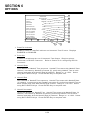
A d j a ce n t C h a n n e l R e j e c t i o n :
IF BW
(3 dB)
300 kHz
15 kHz
S e l e ct i vi t y
>30.0 dB Down
±485 kHz
±15 kHz
Demodulation Output
0.20
0.10
0.04
0.02
AM:
1 . 1 3 V r m s ( ± 0 . 0 6 V r m s) ( 8 0 %
modulation)
∅M:
0.2 Vpk/Rad, ±10%
1-15
Vpk/kHz,
Vpk/kHz,
Vpk/kHz,
Vpk/kHz,
±10%
±10%
±10%
±10%
FM:
(10 kHz range)
(20 kHz range)
(50 kHz range)
(100 kHz range)
SECTION 1
INTRODUCTION
SELECTIVE RF CO UNTER
Frequency Range:
250 kHz to 1 GHz (The received
frequency must be within the IF
bandpass of the COM-120C.)
Tunable Range:
0 Hz to 1 GHz (characteristics below
250 kHz are not specified)
Resolution:
1 H z ( 1 0 se c g a t e t i m e )
1 0 H z ( 1 se c g a t e t i m e )
Accuracy:
S a m e a s M a st e r O sci l l a t o r , ± 2 H z
RF Level:
T/R Connector:
0 to +53 dBm
ANT Connector:
-60 to 0 dBm
RF FREQ UENCY ERROR METER
Meter Range:
0 Hz to 100 kHz
Meter Accuracy:
S a m e a s M a st e r O sci l l a t o r , ± 2 co u n t s.
Meter Resolution:
1 H z ( 1 0 se c g a t e t i m e )
1 0 H z ( 1 se c g a t e t i m e )
RF Frequency Range:
250 kHz to 1 GHz (The received
frequency must be within the IF
bandpass of the COM-120C.)
RF Level:
T/R Connector:
0 to 53 dBm
ANT Connector:
-60 to 0 dBm
AF FREQ UENCY COUNTER
Frequency
Range:
10 Hz to 20 kHz
Accuracy:
S a m e a s M a st e r O sci l l a t o r , ± 1 co u n t .
Resolution:
0 . 1 H z ( 1 se c g a t e t i m e , 1 0 t o 5 0 0 H z)
1 H z ( 1 s e c g a t e t i m e , 5 0 0 H z t o 2 0 k H z)
0 . 1 H z ( 1 0 se c g a t e t i m e )
Input Signal Level
SCOPE/DVM Input:
9 0 m V p p ( 5 0 m V r a n g e , a n y w a ve f o r m )
AUDIO/DATA Input:
4 5 0 m V p p ( a n y w a ve f o r m )
1-16
SECTION 1
INTRODUCTION
FREQ UENCY MODULATION METER
Range:
2, 5, 10, 20, 50, 100 kHz full scale
Resolution:
10 Hz (2, 5 and 10 kHz range)
100 Hz (20, 50 and 100 kHz ranges)
Accuracy:
±5% full scale, ±50 Hz, ±1 digit + source
r e si d u a l F M ( 3 0 0 kH z I F B W , 1 kH z t o n e ,
5 kHz deviation, C-Message weighted
filter)
Modulation Rate:
0 to 20 kHz
Carrier Range:
250 kHz to 1 GHz (The received
frequency must be within the IF
bandpass of the COM-120C.)
Carrier Level:
T/R Connector:
0 to +53 dBm
ANT Connector:
-60 to 0 dBm
∅ M METER
Range:
1, 2, 5, 10 rad peak full scale
Resolution:
0.01 rad (1 and 2 rad scales)
0.1 rad (5 and 10 rad scales)
Accuracy:
±5% of full scale ±0.1 rad, ±1 count +
so u r ce r e si d u a l P M ( 3 0 0 kH z I F B W ,
1 kHz tone, 1.0 rad deviation, C-Message
weighted filter)
Modulation Rate:
100 Hz to 6 kHz
Carrier Range:
250 kHz to 1 GHz (The received
frequency must be within the IF
bandpass of the COM-120C.)
Carrier Level:
T/R Connector:
0 to +53 dBm
ANT Connector:
-60 to 0 dBm
1-17
SECTION 1
INTRODUCTION
AM MODULATION METER
Range:
1% to 100%
Resolution:
0.1%
Accuracy:
±5% of full scale, ±1 count + source
r e si d u a l A M ( 3 0 0 kH z I F B W , 1 kH z t o n e ,
50% AM depth, C-Message weighted
filter)
Modulation Rate:
50 Hz to 10 kHz
Carrier Range:
250 kHz to 1 GHz (The received
frequency must be within the IF
bandpass of the COM-120C.)
Carrier Level:
T/R Connector:
0 to +53 dBm
ANT Connector:
-60 to 0 dBm
AGC Attack Time:
50 ms maximum
RF PO WER METER
Meter Ranges:
2 mW to 200 W in a 1-2-5 sequence
Resolution:
1% of full scale or 0.1 mW, whichever is
greater
Accuracy:
±10%, ±0.1 mW, ±1 digit (>200 mW, 15°C
to 36°C)
±15%, ±0.1 mW, ±1 digit (<200 mW
below 15°C and above 35°C)
Frequency Range:
1.5 MHz to 1 GHz
RF Level Range:
2 mW to 200 W average power
U sa b l e L e ve l :
0.2 mW to 200 W average power
(characteristics below 2 mV not
specified)
Operating Conditions:
50 W CW continuous
100 W CW (90 sec/3
150 W CW (30 sec/3
200 W CW (15 sec/3
VSWR:
1.15:1 (0.25 to 100 MHz)
1.23:1 (100 to 400 MHz)
1.38:1 (400 MHz to 1 GHz)
Alarms:
Audible and visual (if applied power
exceeds 200 W in the 200 W range or the
COM-120C’s Power Termination
Assembly temperature exceeds 105°C)
1-18
(50°C)
min, 50°C)
min, 50°C)
min, 50°C)
SECTION 1
INTRODUCTION
RECEIVE LEVEL METER
Range:
- 1 0 1 t o - 3 0 d B m ( 1 5 kH z I F B W )
- 8 0 t o - 3 0 d B m ( 3 0 0 kH z I F B W )
Accuracy:
±3 dB
Frequency Range:
250 kHz to 1 GHz (The received
frequency must be within the IF
bandpass of the COM-120C.)
DISTORTION METER
Range:
1% to 20%
Resolution:
0.1%
Accuracy:
±0.5% distortion, ±1 digit (1% to 10%)
±2% distortion, ±1 digit (>10 to 20%)
Signal Frequency:
1 kHz sinewave
Signal Level:
SCOPE/DVM Input:
0.03 to 200 Vrms
AUDIO/DATA Input:
0.15 to 15 Vrms
SINAD METER
Range:
3 to 30 dB
Resolution:
0.1 dB
Accuracy:
± 1 d B , ± 1 co u n t ( a t 1 2 d B S I N A D )
Signal Frequency:
1 kHz sinewave
Signal Level:
SCOPE/DVM Input:
0.03 to 200 Vrms
AUDIO/DATA Input:
0.15 to 15 Vrms
1-19
SECTION 1
INTRODUCTION
DIGITAL VO LTMETER
Ranges:
50 mV to 200 V in a 1-2-5 sequence
Range:
DC:
10 mV to 200 Vdc (SCOPE/DVM input)
AC:
10 mV to 200 Vrms (SCOPE/DVM input)
150 mV to 15 Vrms (AUDIO/ DATA input)
Resolution:
3.5 digit
Accuracy:
±5% full scale, ±5 mV ±1 digit
(SCOPE/DVM input)
±7% full scale, ±5 mV ±1 digit
(AUDIO/DATA input)
Frequency:
DC, 50 Hz to 20 kHz
Input Impedance:
1 M Ω u n b a l a n ce d ( S C O P E / D V M / S I N A D
input)
1 0 0 kΩ , u n b a l a n ce d ( A U D I O / D A T A i n p u t )
O SCILLO SCO PE
Bandwidth (3 dB):
5 0 kH z
Vertical
Ranges:
10 mV to 50 V/div in a 1-2-5 sequence
Maximum Input:
200 rms
Accuracy:
5% full scale
Resolution:
1% full scale, 256 data points, 8 major
divisions
Coupling:
DC, AC and GND
Horizontal
Ranges:
1 0 0 µ s t o 2 0 0 m s / d i v i n a 1 - 2 - 5 s e q u e n ce
Resolution:
1% full scale, 500 data points, 10 major
divisions
Accuracy:
1% full scale
Input Impedance:
1 MΩ, unbalanced (nominal)
1-20
SECTION 1
INTRODUCTION
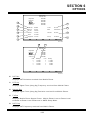
SPECTRUM ANALYZER
Center Frequency:
250 kHz to 1 GHz
Tunable Range:
0 Hz to 1 GHz (characteristics below
250 kHz are not specified)
Resolution:
100 Hz
F r e q u e n cy S p a n
Ranges:
1 kHz to 100 MHz/div in a 1-2-5
sequence and zero span
Accuracy:
±5% of span width
Operational Modes:
N o r m a l , S p l i t S cr e e n
M o d e s:
S ca n W i d t h
100 MHz/div
50 MHz
20 MHz
10 MHz
5 MHz
2 MHz
1 MHz
500 kHz
200 kHz
100 kHz
50 kHz
20 kHz
10 kHz
5 kHz
2 kHz
1 kHz
0 kHz
1-21
R e so l u t i o n B W
3 MHz
3 MHz
3 MHz
3 MHz
300 kHz
300 kHz
300 kHz
30 kHz
30 kHz
30 kHz
30 kHz
3 kHz
3 kHz
3 kHz
300 Hz
300 Hz
30 kHz
SECTION 1
INTRODUCTION
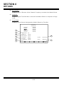
L e ve l
Display:
Log, 2 and 10 dB/div
V e r t i ca l R e so l u t i o n :
1 dB
R a n g e ( D yn a m i c) :
60 dB
Bandwidth Switching Error:
<3 dB
Log Linearity:
± 2 d B ( r e f e r e n ce d t o - 4 0 d B m , 1 5 ° t o
35°C)
± 3 d B ( r e f e r e n ce d t o - 4 0 d B m , 0 ° t o 1 5 ° C
and 35° to 50°C)
Input Attenuator:
0, 30 dB (ANT Connector)
INPUT/OUTPUT CONNECTORS
RS-232 Connector
Operations Mode:
Off, PC (Input/Output)
Baud Rates:
100, 150, 300, 600, 1200, 2400, 4800,
9600, 19200, 38400
S t o p B i t s:
1, 2
Parity:
O d d , E ve n , N o n e
H a n d sh a ke :
None, Xon/Xoff, CTS/RTS
MASTER OSCILLATOR
TCXO
F r e q u e n cy:
10 MHz
Uncertainty:
±0.1 ppm
Temperature Stability:
±0.2 ppm (0° to 50°C)
Aging Rate:
± 0 . 5 p p m / ye a r
PO WER REQ UIREMENTS
Line Voltage:
100 to 120 VAC at 60 Hz
220 to 240 VAC at 50 Hz
DC Input:
1 2 V d c, 2 4 - 3 0 V d c
Power Consumption
AC:
1 1 0 V A C , 1 5 0 W m a xi m u m , 1 1 0 W t yp i ca l
2 3 0 V A C , 1 5 0 W m a xi m u m , 9 5 W t yp i ca l
DC:
1 5 0 W m a xi m u m , 9 0 W t y p i ca l
1-22
SECTION 1
INTRODUCTION
FUSE REQ UIREMENTS
AC Fuses:
100 to 120 VAC:
3 . 0 A , 2 5 0 V , T yp e F ( 5 x 2 0 m m )
220 to 240 VAC:
3 . 0 A , 2 5 0 V , T yp e F ( 5 x 2 0 m m )
DC Fuse:
1 0 A , 3 2 V , T yp e F ( A G C )
B a t t e r y F u se :
1 0 A , 3 2 V , T yp e F ( A G C )
SAFETY CONDITIONS
Use:
Non-condutive pollution only
Altitude:
≤4000 meters (13,124 feet)
Operating Temperatures:
0° to 50°C
R e l a t i ve H u m i d i t y :
≤80% for temperatures up to 31°C
decreasing linearly to 50% at 40°C
Mains Supply Voltage Fluctuations:
≤±10% of the nominal voltage
Transient Overvoltages:
According to Installation Category II
Pollution Degree:
2
GENERAL CHARACTERISTICS
Dimensions:
4 0 . 0 c m ( 1 5 . 7 5 ” ) w i d e , 1 9 . 0 cm ( 7 . 5 ” )
high, 42.9 cm (16.875”) deep (without
bail handle and front panel cover)
4 4 . 0 c m ( 1 7 . 3 2 ” ) w i d e , 1 9 . 0 cm ( 7 . 5 ” )
high, 53.7 cm (21.125”) deep (with bail
handle and front panel cover)
Weight:
1 7 . 3 k g ( 3 8 . 5 l b s . ) (without options, lid,
accessories)
1-23
SECTION 1
INTRODUCTION
THIS PAGE INTENTIONALLY LEFT BLANK.
1-24
SECTION 2
INSTALLATION
2-1
GENERAL
This section contains infor mation on pr epar ing the CO M- 120C for use.
installation and oper ating pr ecautions for safe use of the Unit.
2-2
Also listed ar e
PRECAUTIONS
Befor e oper ating this instr ument, the oper ator should be thor oughly familiar with all
aspects of this manual.
For oper ator safety and to pr event damage to this instr ument, the following oper ating
pr ecautions should be obser ved at all times.
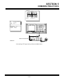
WARNING:
DO NOT USE A THREE- PRONG TO TWO-PRONG ADAPTER PLUG.
DOING SO CREATES A SHOCK HAZARD BETWEEN THE CHASSIS
AND ELECTRICAL GROUND.
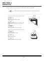
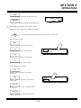
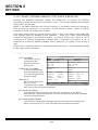
CAUTION:
THE T/R CO NNECTO R ACCEPTS NO MO RE THAN 200 W. MAXIMUM
OPERATION TIME FOR MEASUREMENT USING THE T/R
CONNECTOR:
CONTINUOUS ON AT 50 W AND 50 °C AMBIENT.
30 SEC O N AND 3 MIN O FF AT 100 W AND 50°C AMBIENT.
15 SEC O N AND 3 MIN O FF AT 200 W AND 50°C AMBIENT.
MAXIMUM CONTINUOUS INPUT
INTO THIS CONNECTOR…
…MUST NO T EXCEED THIS
MAXIMUM O R DAMAG E TO THE
CO M- 120C MAY RESULT
ANTENNA
0.25 W MAX
DEMO D
20 V MAX
EXT MO D
20 V MAX
SCO PE/DVM
200 V MAX
AUX RF O UT
0.25 W MAX
MIC/ACC
20 V MAX
AUDIO/DATA IN
30 V MAX
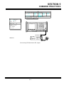
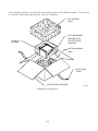
This Equipment Contains Par ts Sensitive To Damage By
Electr ostatic Dischar ge ( ESD) .
2-1
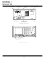
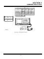
SECTION 2
INSTALLATION
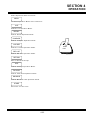
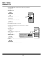
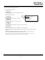
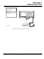
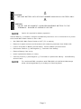
DC INPUT
CONNECTOR
DC FUSE COVER
AC INPUT CONNECTOR
AC FUSE COVER
MAIN POWER SWITCH
BATTERY ACCESS PANEL
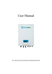
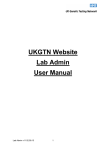
00607300
CO M- 120C Rear Panel
POWER ON INDICATOR
POWER APPLIED INDICATOR
POWER ON KEY
00607028
CO M- 120C Front Panel
2-2
SECTION 2
INSTALLATION
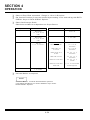
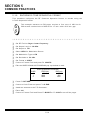
2-3
POWER UP PROCEDURES
The Inter nal Batter y, if installed, char ges automatically when the
connected to a power sour ce and the Main Power Switch is set to O N.
The Power Supply is designed to sense
automatically with no fur ther action r equir ed.
2-3-1
applied
ac
voltage
CO M- 120C
and
compensate
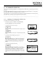
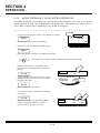
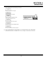
APPLYING AC POWER
o
Connect ac power cor d to AC Input Connector .
o
Plug ac power cor d into power sour ce. Insur e pr oper gr ounding.
o
Set Main Power Switch to O N ( “I” on switch) .
Power APPLIED Indicator lights when power is available.
o
Pr ess CO M- 120C Fr ont Panel Power O N Key to activate Unit. Power O N Indicator
lights.
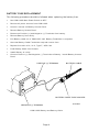
2-3-2
APPLYING EXTERNAL DC POWER
o
Connect dc power cor d to DC Input Connector .
o
Pr oper ly connect non- ter minated ends of dc power cor d to a 10A cur r ent limited dc
power sour ce.
Power APPLIED Indicator lights when power is available.
o
Pr ess CO M- 120C Fr ont Panel Power O N Key to activate Unit. Power O N Indicator
lights.
n OTe
2-3-3
Befor e oper ating unit with 12 V supply, ver ify voltage level at
connector is 12 V or gr eater .
BATTERY POWER OPERATION (OPTION 01)
o
Pr ess CO M- 120C Fr ont Panel Power O N Key.
o
Power O N Indicator lights.
O ption 01 r equir ed for batter y oper ation.
Power cycles off after appr oximately 20 to 25 minutes of continuous oper ation.
Flashing Power ON Indicator denotes low battery charge.
2-3
is
SECTION 2
INSTALLATION
THIS PAGE INTENTIONALLY LEFT BLANK.
2-4
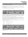
SECTION 3
COMPOSITE
1
2
3
4
5
6
7
8
9
10
11
12
25
24
23
22
21
20
19
18
17
16
15
14
13
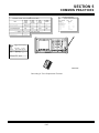
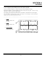
00607167
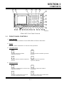
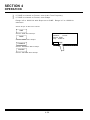
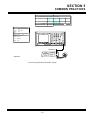
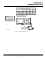
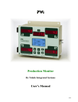
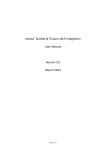
COM-120C Front Panel Controls
3-1
FRONT PANEL CONTROLS
1. Power O N Key
Selection toggles between Power APPLIED and Power O N states.
2. Display
Pr ovides video infor mation of cur r ent test oper ation.
3. Test Mode Keys
GEN
DPLX
A cce s s e s G e n e r a t e M o d e
Operation Screen.
A cce sse s D U P L E X M o d e O p e r a t i o n
S cr e e n .
SPCL
REC
Accesses Special Optional
Operation Modes.
A cce s s e s R e c e i v e M o d e O p e r a t i o n
Screen.
4. Instr ument Keys
SCOPE
MTRS
A c c e s s e s I n d e p e n d e n t O s c i l l o sc o p e
Operation Screen.
A cce sse s I n d e p e n d e n t M e t e r
Functions.
AUDIO
GEN
ANLYZ
Accesses Independent Spectrum
Analyzer Operation Screen.
Accesses Independent Audio/Data
Generators Functions.
3-1
SECTION 3
COMPOSITE
5. DATA ENTRY Keys
0
thru
9
U s e t o e n t e r n u m e r i c ( 0 - 9 ) va l u e s.
Use to enter decimal point in
numeric values.
∗
SHIFT
Use for DTMF functions.
Accesses alphabetic function of
F r o n t P a n e l K e ys. S e e S h i f t
Character Table.
#
ENTER
Use for DTMF functions.
Selects a data field for edit or
completes an editing procedure.
+/Use to set sign of entered value.
6. CONTROL Keys
ESC
TAB
Use to escape an editing procedure
without change to parameters.
M o ve s cu r so r t o p r e d e t e r m i n e d
areas to simplify editing.
HOLD
SCRN
U s e t o f r e e z e c u r r e n t s cr e e n t o
observe data or print the screen.
Press HOLD SCRN Key again to
return Test Set to normal
operation.
SHIFT
+
ESC
D e l e t e s t h e ch a r a ct e r t h e cu r so r i s
on when editing.
START
STOP
Use to start and stop the Reset
One Shot in Oscilloscope
Operation, Bit Error Rate Meter
(Option 07) and LTR Trunking
(Option 14)
3-2
SECTION 3
COMPOSITE
FRONT PANEL KEY
SHIFT CHARACTER
GEN
A
REC
B
1
C
2
D
3
E
+/-
F
DPLX
G
SPCL
H
4
I
5
J
6
K
•
L
SCOPE
M
ANLYZ
N
7
O
8
P
9
Q
MTRS
R
AUDIO GEN
S
❉
T
0
U
#
V
STORE
W
RCL
X
SHOW LIST
Y
SETUP
Z
TAB
[space]
SHIFT + ESC
Deletes Character
Shift Char acter Table
3-3
SECTION 3
COMPOSITE
7. ANTENNA Connector
Input connector to monitor "off- the- air " signals. Also used as a connection for low
power ( 0.25 W maximum) signals.
CAUTION:
DO NOT EXCEED 0.25 W MAXIMUM CONTINUOUS INPUT OR DAMAGE TO
THE CO M- 120C MAY RESULT.
8. SQ UELCH Control
Adjusts squelch level of r eceived signal.
9. VO LUME Contr ol
Contr ols volume of speaker .
10. PHO NES Connector
Pr ovides access for using Headphones when audio signal is pr ovided to speaker .
11. DATA SCRO LL Spinner
Allows oper ator to scr oll thr ough cur r ent test mode oper ation scr een, scr oll
thr ough lists of par ameter selections and actively incr ease and decr ease one digit
of numer ic par ameter s. Cur r ent test mode oper ation scr een changes with enter ed
data; changed par ameter becomes cur r ent default unless ENTER Key is pr essed.
Pr essing ESC Soft Function Key r etur ns changed par ameter to pr evious setting.
12. T/R Connector
50 Ω Connector for high power input or output signals.
CAUTION:
DO NO T EXCEED 200 W MAXIMUM CO NTINUO US INPUT O R DAMAG E TO
THE CO M- 120C MAY RESULT.
13. AUX RF O UT Connector
50 Ω Auxiliar y output connector for RF Signals.
CAUTION:
DO NOT EXCEED 0.25 W MAXIMUM CONTINUOUS INPUT OR DAMAGE TO
THE CO M- 120C MAY RESULT.
3-4
SECTION 3
COMPOSITE
14. AUDIO /DATA G EN Connector
600 Ω connector for output of audio and data gener ator s. Access is selectable
fr om individual gener ator setup scr eens.
CAUTION:
DO NOT EXCEED 20 V MAXIMUM CONTINUOUS INPUT OR DAMAGE TO
THE CO M- 120C MAY RESULT.
15. DEMO D Connector
600 Ω connector for output of demodulated signals. Access is selectable fr om
individual gener ator setup scr eens.
CAUTION:
DO NOT EXCEED 20 V MAXIMUM CONTINUOUS INPUT OR DAMAGE TO
THE CO M- 120C MAY RESULT.
16. MIC/ACC Connector
Pr ovides access for micr ophone or accessor y equipment both gener ate and
r eceive lines ar e available.
CAUTION:
DO NOT EXCEED 20 V MAXIMUM CONTINUOUS INPUT OR DAMAGE TO
THE CO M- 120C MAY RESULT.
17. DATA SCRO LL Keys
Allows oper ator to scr oll thr ough cur r ent test mode oper ation scr een, scr oll
thr ough list of par ameter selections and actively incr ease and decr ease one digit
of numer ic par ameter s.
Incr easing and decr easing digits affects higher digits in par ameter .
Cur r ent test mode oper ation scr een changes with changed data; changed
par ameter becomes cur r ent default unless ENTER Key is pr essed.
Pr essing ESC ( Escape) Soft Function Key r etur ns changed par ameter to pr evious
setting.
18. EXT MO D
100 k Ω connector allows input for exter nal modulation sour ce.
CAUTION:
DO NOT EXCEED 20 V MAXIMUM CONTINUOUS INPUT OR DAMAGE TO
THE CO M- 120C MAY RESULT.
3-5
SECTION 3
COMPOSITE
19. AUDIO /DATA IN Connector
100 k Ω connector allows input of exter nal audio and data signals.
CAUTION:
DO NOT EXCEED 20 V MAXIMUM CONTINUOUS INPUT OR DAMAGE TO
THE CO M- 120C MAY RESULT.
20. SCO PE/DVM Connector
1 M Ω input to O scilloscope and Digital Voltmeter . CAT II.
CAUTION:
DO NO T EXCEED 200 V MAXIMUM CO NTINUO US INPUT O R DAMAG E TO
THE CO M- 120C MAY RESULT.
21. MEMO RY Keys
STORE
Selection allows operator to store
current Operation Screen and all
current parameters for future
access.
RCL
Selection allows operator to recall
previously stored Operation
S cr e e n s.
SHOW
LIST
Provides access to menu of all
storage lists.
SETUP
P r o vi d e s a cce ss t o se t u p m e n u f o r
syst e m i n f o r m a t i o n a n d syst e m
configuration.
22. PCMCIA Car d Slot
Pr ovides access to enhance softwar e capability.
23. Soft Function Keys
Pr ovide access to defined function.
24. Power O N Indicator
Denotes system is on when lit.
25. Power APPLIED Indicator
Denotes power is pr ovided to the system when lit.
3-6
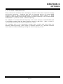
SECTION 3
COMPOSITE
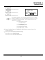
27
26
28
34
29
33
31
30
32
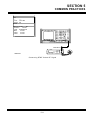
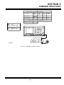
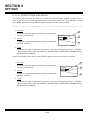
00607261
CO M- 120C Rear Panel Contr ols
3-2
REAR PANEL CONTROLS
26. DC Input Connector
Accepts dc power cor d to supply dc power ( 12, 24 to 30 Vdc) to CO M- 120C.
CAUTION:
DO NO T EXCEED 30 Vdc O R DAMAG E TO THE CO M- 120C MAY RESULT.
27. DC Fuse
10 A, 32 V, Type F, AG C Fuse is pr ovided for dc oper ation.
CAUTION:
O NLY USE 10 A, 32 V TYPE F FUSE O R DAMAG E TO THE CO M- 120C MAY
RESULT.
28. AC Input Connector
Accepts ac power cor d to supply ac power to CO M- 120C.
CAUTION:
DO NO T EXCEED 265 VAC O R DAMAG E TO THE CO M- 120C MAY RESULT.
3-7
SECTION 3
COMPOSITE
29. AC Fuse
Two 3.0 A, 250 V, Type F, 5 x 20 mm fuses ar e pr ovided for ac oper ation.
CAUTION:
O NLY USE 3 A FUSE O R DAMAG E TO THE CO M- 120C MAY RESULT.
30. Main Power Switch
Switches power applied O N an O FF.
31. Batter y Access Panel
Pr ovides access to batter y.
32. RS- 232 Connector
Pr ovides ser ial inter face for r emote oper ations with CO M- 120C.
33. G PIB Connector ( O ption)
IEEE- 488 Connector pr ovides par allel inter face for r emote oper ations with
CO M- 120C.
34. Refer ence Connector
Pr ovides connection for input of exter nal 10 MHz Refer ence Signal.
3-8
SECTION 3
COMPOSITE
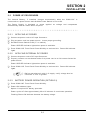
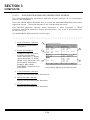
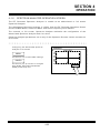
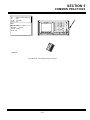
3-3
SCREENS, SOFT FUNCTION KEYS AND MENUS
The following comments apply to all O per ation Scr eens within the CO M- 120C. Reading
and under standing these notes is the r esponsibility of the oper ator .
Due to the level of detail r equir ed to fully descr ibe all facets of the CO M- 120C, only
sur face infor mation is pr ovided to help educate the oper ator .
3-3-1
SOFT FUNCTION KEYS
Soft Function Keys ar e alphabetically defined in Appendix D.
3-3-2
CURSOR MOVEMENT
A cur sor , in the shape of a box, is used to identify what is cur r ently editable. Ther e ar e
two methods to move the Cur sor ar ound the active scr een.
Use DATA SCRO LL Keys as long as the cur r ent Cur sor location is not being edited.
O r use TAB Function as follows:
o
Pr ess TAB Key.
o
Enter value in desir ed scr een location using DATA ENTRY Key( s) .
o
Pr ess ENTER Key to complete the oper ation.
3-3-3
EDITING FIELDS USING DATA SCROLL KEYS AND SPINNER
All fields can be edited using DATA SCRO LL Keys and/or DATA SCRO LL Spinner .
Editing Numer ic Data Fields is a special case and is cover ed in par a 4- 1- 3. Edit the
r emainder of the fields using DATA SCRO LL Keys and/or DATA SCRO LL Spinner as
follows:
o
Position cur sor on field selected for edit using DATA SCRO LL Keys or TAB
Function.
o
Pr ess ENTER Key to highlight field.
o
Pr ess DATA SCROLL Key ( ↑) to move up thr ough sear ch field and DATA SCRO LL
Key ( ↓) to move down thr ough sear ch field. Alter nate method is to use DATA
SCRO LL Spinner . Tur ning DATA SCRO LL Spinner clockwise per for ms same
oper ation as pr essing DATA SCRO LL Key (↑) .
o
Pr ess ENTER Key to complete oper ation.
3-9
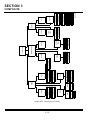
CO M- 120C Composite Hier ar chy
3-10
GEN
RF
MODLTN
RF
TONE/DATA
MODLTN
BIT ERROR RATE
AMPS CELLULAR
LTR TRNKNG
EDACS TRNKNG
MPT1327 TRNKNG
SPCL
DPLX
REC
RF
AF GEN
MODLTN
TONE/DATA
SINAD/DIST/DEV
REC LVL
REC
RF
MODLTN
FILTERS
SINAD/DIST
AF LEVEL
SCOPE/ANLYZ
GEN
MODE
MTRS
AF COUNTER
SINAD METER
DVM
DIST METER
RF ERROR
AF FREQ
SCOPE/ANLYZ
SCOPE
AUDIO GEN-1
AUDIO GEN-2
DATA GEN
DTMF GEN
GEN
AUDIO
ANLYZ
INSTRUMENTS
COM-120C
STORED FREQ
STORED SETUP
STORED FILES
LIST
SHOW
STORE
SETUP
RCL
00607000
CALIBRATION
CLK/CALENDAR
VERSION
GPIB
RS-232
RUN TIME
DIAGNOSTICS
KEYBOARD
DSP SELFTEST
PCMCIA SETUP
PRINT SCREEN
RESTORE
MEMORY
SECTION 3
COMPOSITE
SECTION 3
COMPOSITE
3-3-4
EDITING NUMERIC DATA FIELDS
The pr imar y method of editing data in numer ic data fields such as fr equencies and
levels is to use DATA ENTRY Keys. The step- by- step pr ocedur e for this method is as
follows:
o
Position cur sor on field selected for data entr y using DATA SCRO LL Keys or TAB
Function.
o
Enter numer ic value using DATA ENTRY Keys.
o
Pr ess ENTER Key to complete oper ation.
A second method to change cur r ent numer ic values in small amounts is to use the DATA
SCRO LL Keys and/or DATA SCRO LL Spinner . This method changes one digit of the
value dir ectly, but mor e significant digits ar e affected indir ectly as the edited digit
passes zer o in either dir ection. The step- by- step pr ocedur e for this method is as
follows:
o
Position cur sor on field selected for data entr y using DATA SCRO LL Keys or TAB
Key.
o
Pr ess ENTER Key to highlight field.
o
Digit in field to be edited is not highlighted. Pr essing DATA SCRO LL Key (→)
moves highlight to less significant digit. Pr essing DATA SCRO LL Key (←) moves
highlight to mor e significant digit.
o
O nce digit to be edited is selected, pr ess DATA SCRO LL Key (↑) to incr ease digit
value and DATA SCRO LL Key (↓) to decr ease digit value. Alter nate method is to
use DATA SCRO LL Spinner . Tur ning DATA SCRO LL Spinner clockwise
incr eases value and counter clockwise decr eases value.
o
Pr ess ENTER Key to complete oper ation.
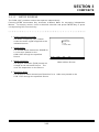
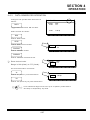
3-3-5
MAKING SELECTIONS FROM MENUS
Whenever the number of selections for the position being edited exceeds the number of
available Soft Function Keys, a MENU Soft Function Key is used. Pr essing the MENU
Soft Function Key opens a window of selections for the cur r ent cur sor location. The
window cur sor is located at the cur r ently active selection.
To choose a differ ent
selection, move the cur sor using the DATA SCRO LL Keys or DATA SCRO LL Spinner to
the selection. Pr ess the ENTER Key to complete the oper ation.
3-3-6
ESCAPING FROM EDIT WITHOUT CHANGE
An edit pr ocedur e can be exited at any time, without change, by pr essing the ESC Key.
3-11
SECTION 3
COMPOSITE
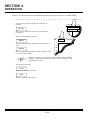
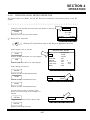
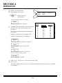
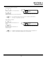
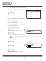
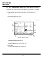
3-3-7
RF GENERATE SCREEN
The RF G ener ate O per ation Scr een defines and activates the CO M- 120C RF G ener ator
and is accessed by pr essing the G EN Test Mode Key.
The RF G ener ate O per ation Scr een displays in the configur ation last used.
1. Header Bar
1
Displays cur r ent oper ation
mode.
2
3
GENERATE
17
RF:
FL:
Level:
Output:
GEN1
SCOPE
2. RF Field
Displays current RF Generate
Frequency from 0.0000 to
1000.0000 MHz.
Set Refer ence and Sweep
Functions ar e not active
simultaneously.
16
15
1 kHz
SOURCE:
1 ms/div
Int Mod
500.0000 MHz
OFF
-130.0 dBm
T/R
13
12
6
7
Shape:
8
SINAD
0.00 Vrms
0
0.05
Sine
Audio/Data Filters
LINE:
- - - dB
55
0
AF DEC
HP: OFF
LP: OFF
BP: OFF
3. FL ( Fr equency List) Setting
5
Mod Src: GEN1
FM
Deviation:
5.00 kHz
Format: TONE
Freq: 1000.0 Hz
14
AF LEVEL
4
9
11
Displays selected Fr equency
10
List number ( FL- 00 to FL- 99)
RF G ener ate Scr een
when active. Blank if
inactive. RF Field ( 2)
echoes fr equency of selected Fr equency List setting. Editing RF Field ( 2)
deactivates Fr equency List Function.
00607167
4. Fr equency List Label
Displays optional Fr equency List Label. Blank if Fr equency List Label is not used.
5. O utput Level
Displays O utput Level in selected units. If T/R Connector is selected for O utput
( 6) , r ange is - 130 to - 20 dBm, 0.07 to 22360.6 µV, 0.0000 to 22.3606 mV and
0.000000 to 0.022360 V. If AUX RF Connector is selected for O utput ( 6) , r ange is
- 130 to - 13 dBm, 0.07 to 50059.3 µV, 0.0000 to 50.0593 mV and 0.000000 to
0.050059 V.
6. O utput
Displays connector selected for output. Displays T/R, T/R G ate, AUX or AUX
G ate. If G ate O utput is selected, output is active only when micr ophone attached
to MIC/ACC Connector is keyed. Default output connector is T/R Connector .
3-12
SECTION 3
COMPOSITE
7. Modulation Sour ce Window
Displays active Modulation Sour ces. Inactive Modulation Sour ces ar e not shown.
If two ( or mor e) sections of the RF Modulator ar e set in conflict ( e.g. G EN1 set for
PM and G EN2 set for FM, or G EN1 set for 0.01 kHz deviation and G EN2 set for
2.60 kHz deviation) the scr een displays the invalid sour ce gr ayed out.
8. Modulation Sour ce Block
Displays selected Modulation Sour ce and appr opr iate data. Selections include
G EN1 ( Audio G ener ator 1) , G EN2 ( Audio G ener ator 2) , DTMF ( DTMF Tone
G ener ator ) , DATA ( DATA G ener ator ) , EXT ( Exter nal Modulation) and MIC
( Micr ophone Modulation) .
9. Audio/Data Filter s Block
Displays cur r ent filter infor mation for selected analog signal. Selections include
AF Decode Line, Data Decode Line and Speaker /Headphones Line.
10. Soft Function Key Definitions
Functions ar e r edefined with each field of the cur r ent oper ation scr een.
11. SINAD/Distor tion Meter s
Displays selected Meter O per ation. Selections ar e SINAD or Distor tion Meter s.
12. AF Level Meter
Displays AF LEVEL METER O per ation.
13. O scilloscope Sweep
Displays editable O scilloscope Sweep.
14. Sour ce
Displays editable O scilloscope Sour ce.
15. O scilloscope Scale
Displays editable O scilloscope Ver tical Scale. Ver tical Scale value and r ange
selections is dependent on Sour ce.
16. Scope/Analyzer Scr een
Displays digitized tr ace of specified signal as O scilloscope or Spectr um Analyzer .
17. Scope/Analyzer Pr ompt
Displays cur r ent oper ation function. Used to toggle between two functions.
3-13
SECTION 3
COMPOSITE
3-3-8
RF RECEIVE SCREEN
The RF Receive O per ation Scr een is used to define and activate the CO M- 120C RF
Receiver and is accessed by pr essing the REC Test Mode Key.
The RF Receive O per ation Scr een displays in the configur ation last used.
1. Header Bar
Displays cur r ent oper ation
mode.
1
19
2. RF Field
Displays cur r ent RF
Receive Fr equency.
Range is fr om 0.0000 to
1000.0000 MHz.
Scan Function sear ches a
specified Fr equency List
( 3) r ange, stopping for a
selected time per iod or
when squelch is br oken.
18
17
16
RECEIVE
dBm
-40
-50
-60
-70
-80
-90
-100
-110
-120
2
4
5
6
105.0000 MHz
RF:
OFF
FL:
ANT Atten:
0 dB
Input:
FM IF BW: 15 kHz
Demod:
OFF
AF GEN OUT
MOD MTR
LINE:
OFF LPF: 20kHz
HPF:
OFF
BPF:
POCSAG
Tone/Data Code:
ANALYZER
AF FREQUENCY:
1 MHz
0
RF ERROR
15
3
- 0.034 kHz
104.999966 MHz
-100
100
Hz
DISTORTION:
REC LEVEL
%
DEVIATION
- 39.1 dBm
-120
+++
-25
- 0.05
0
7
8
9
10
kHz
2
14
11
12
Sweep Function sweeps a
13
set r ange of fr equencies,
RF Receive Scr een
incr easing or decr easing
fr equency at set r ate and
stopping for a set time or when squelch is br oken.
00607009
∆ Function allows change of fr equency in selected incr ement (∆) .
3. FL ( Fr equency List) Setting
Displays selected Fr equency List number ( FL- 00 thr ough FL- 99) when active and
O FF when inactive. RF Field ( 2) echoes fr equency of selected Fr equency List
setting. Dir ectly editing RF Field ( 2) inactivates FL Setting. Displays optional
Fr equency List Label if used.
4. Input Connector
Displays connector selected for input. Displays either T/R or ANT.
5. Demodulation Type
Displays selected Demodulation Type. Selections include FM, AM or PM.
6. Attenuation
Displays selected attenuation of input signal. Displays either 0 or 30.
3-14
SECTION 3
COMPOSITE
7. IF Bandwidth
Displays selected IF Bandwidth. Selections include 15 and 300 kHz.
8. AF G en O ut Field
Pr essing ENTER, when cur sor is on this field, accesses setup menu for AF
G ener ator sour ces. Menu displays each sour ce individually. Sour ces available
include G EN1 ( Audio G ener ator 1) , G EN2 ( Audio G ener ator 2) , DTMF ( DTMF
Tone G ener ator ) and DATA ( DATA G ener ator ) .
9. Audio/Data Filter s Block
Displays cur r ent filter infor mation for selected analog signal. Selections include
Modulation Meter s Line, DTMF/SINAD Line, AF Counter Line, Data Decode Line
and Speaker / Headphones Line.
10. Tone/Data Code Field
Displays selected Tone/Data Type and decoded data.
11. Distor tion/SINAD/Modulation Reading
Displays distor tion r eading of r eceived signal if Distor tion is selected.
Displays SINAD r eading of r eceived signal if SINAD is selected.
Displays modulation r eading in units of selected DEMO D Type ( 5) if Modulation is
selected.
This field is inter active with Distor tion/SINAD/Modulation Meter ( 12) and displays
r eading when Distor tion/SINAD/Modulation Meter ( 12) displays meter .
The same r eading cannot be displayed twice. Selection of a specific r eading
changes sour ce of nonedited field to another sour ce
12. Distor tion/SINAD/Modulation Meter
Displays distor tion r eading of r eceived signal if Distor tion is selected.
Displays SINAD r eading of r eceived signal if SINAD is selected.
Displays modulation r eading in units of selected DEMO D Type ( 5) if Modulation is
selected.
This field is inter active with Distor tion/SINAD/Modulation Reading ( 11) and field
displays complete meter when Distor tion/ SINAD/Modulation Reading ( 11)
displays r eading only.
The same r eading cannot be displayed twice. Selection of a specific r eading
changes sour ce of nonedited field to another sour ce. O ne sour ce must always be
Modulation.
13. Soft Function Key Definitions
Functions ar e r edefined with each field of the cur r ent oper ation scr een.
3-15
SECTION 3
COMPOSITE
14. Power /Received Level Meter
Power Meter displays power level of signal r eceived thr ough T/R Connector only
in dB and Watts. RECEIVED LEVEL Meter displays r efer enced Power Level of
signal r eceived thr ough ANTENNA Connector only in dBm and µV.
15. R F Er r or Meter
Displays differ ence in RF Field ( 2) and fr equency of r eceived signal.
16. AF Fr equency Counter
Displays Audio Fr equency of r eceived signal.
17. Scan Width
Displays cur r ent Scan Width. This field is editable.
18. Scope/Analyzer Scr een
Displays digitized tr ace of specified signal as O scilloscope or Spectr um Analyzer .
19. Scope/Analyzer Pr ompt
Displays cur r ent oper ation function. Used to toggle between two functions.
3-16
SECTION 3
COMPOSITE
3-3-9
DUPLEX SCREEN
The Duplex O per ation Scr een is used to define and activate the CO M- 120C RF
G ener ator and RF Receiver simultaneously at the same fr equency or offset fr equencies
and is accessed by pr essing the DPLX Test Mode Key.
The Duplex O per ation Scr een displays in the configur ation last used.
1. Header Bar
Displays cur r ent oper ation
mode.
2. Duplex G ener ate Pr ompt
Accesses Duplex Generate
Operation Screen.
3. Duplex G ener ate RF Field
21
20
1
DUPLEX
18
17
16
15
RF :
FL :
Input :
Demod :
2
RECEIVE AND GENERATE
GENERATE
RECEIVE
19
14
Displays cur r ent Duplex
G ener ate Fr equency.
Range is 0.0000 to
1000.0000 MHz.
22
RF :
Offset :
Level :
Output :
525.0000 MHz
OFF
T/R
Atten: 0 dB
FM
IF BW: 15 kHz
Tone/Data Code:
- - -
DCS
DEVIATION:
5.0 kHz
DISTORTION:
12
RF Power:
RF Error Freq:
GEN1
3
4
5
6
7
AF FREQUENCY
13
525.0000 MHz
0.0000 MHz
- 40.0 dBm
T/R
Mod Src : GEN 1
FM
Deviation :
5.0 kHz
Format : TONE
Freq : 1000.0 Hz
1000 Hz
3.0
0.0
%
mW
Shape : SINE
8
0.001 kHz
11
10
4. Fr equency O ffset
00607041
9
Displays fr equency
differ ence between
Duplex Scr een
Duplex G ener ate RF Field
( 3) and Duplex Receive RF Field ( 20) . Range is fr om - 999.7500 to 999.750 MHz.
5. O utput Level
Displays O utput Level. If T/R Connector is selected for O utput ( 6) , r ange is - 130
to - 40 dBm, 0 to .002236 V, 0 to 2.2360 mV or 0.07 to 2236.0 µV. If AUX RF
Connector is selected for O utput ( 6) , r ange is - 130 to - 13 dBm, 0 to 0.050059 V,
0 to 50.0593 mV or 0.07 to 50059.3 µV.
6. O utput
Displays O utput Connector . Displays T/R, T/R G ate, AUX or AUX G ate. G ated
O utput is active only when micr ophone, attached to MIC/ACC Connector , is keyed.
7. Modulation Sour ce Window
Displays active Modulation Sour ces. Inactive Modulation Sour ces ar e not shown.
If two ( or mor e) sections of the RF Modulator ar e set in conflict ( e.g. G EN1 set for
PM and G EN2 set for FM, or G EN1 set for 0.01 kHz deviation and G EN2 set for
2.60 kHz deviation) the scr een displays the invalid sour ce gr ayed out.
3-17
SECTION 3
COMPOSITE
8. Modulation Sour ce Block
Displays selected Modulation Sour ce. Selections include G EN1 ( Audio G ener ator
1) , G EN2 ( Audio G ener ator 2) , DTMF ( DTMF Tone G ener ator ) , DATA ( DATA
G ener ator ) , EXT ( Exter nal Modulation) and MIC ( Micr ophone Modulation) .
9. Soft Function Key Definitions
Functions ar e r edefined with each field of the cur r ent oper ation scr een.
10. RF Er r or Fr equency
Displays differ ence in Duplex Receive RF Field ( 20) and r eceived signal
fr equency.
11. Power /Received Level Reading
Power Meter displays power level of signal r eceived thr ough T/R Connector in W.
RECEIVED LEVEL Meter displays r efer enced Power Level of signal r eceived
thr ough ANTENNA Connector in dBm.
12. SINAD/Distor tion Reading
Displays selected measur ement. Selections include SINAD or Distor tion
Readings.
13. AF Fr equency Reading
Displays Audio Fr equency of demodulated signal.
14. Modulation Reading
Displays modulation r eading in units of selected Demodulation Type ( 17) .
With FM selected, Field displays DEVIATIO N and has r eading in units of kHz.
With AM selected, Field displays MO DULATIO N and has r eading in units of %
Modulation.
With PM selected, Field displays PHASE and has r eading in units of r adians.
15. Tone/Data Code Field
Displays selected Tone/Data Type and decoded data.
16. IF Bandwidth
Displays selected IF Bandwidth. Selections include 15 and 300 kHz.
17. Demodulation Type
Displays selected Demodulation Type. Selections include FM, AM or PM.
18. Input Connector
Displays connector selected for input. Displays either T/R or ANT.
3-18
SECTION 3
COMPOSITE
19. FL ( Fr equency List) Setting
Displays selected Fr equency List number ( FL- 00 thr ough FL- 99) when active and
O FF when inactive.
Duplex Receive RF Field ( 20) echoes fr equency of selected Fr equency List
setting.
Dir ectly editing Duplex Receive RF Field ( 20) inactivates FL Setting.
Displays optional Fr equency List Label if used. Blank if unused.
20. Duplex Receive RF Field
Displays cur r ent Duplex Receive Fr equency. Range is 0.0000 to 1000.0000 MHz.
21. Attenuation
Displays selected attenuation of input signal. Displays either 0 or 30.
22. Duplex Receive Pr ompt
Accesses Duplex Receive O per ation Scr een.
3-19
SECTION 3
COMPOSITE
3-3-10
OSCILLOSCOPE SCREEN
The Independent O scilloscope O per ation Scr een oper ates as an independent piece of
test equipment and is accessed by pr essing the SCO PE Instr uments Key. Input for
O scilloscope O per ation is thr ough the SCO PE/DVM Connector .
The O scilloscope
O per ation Scr een
The O scilloscope O per ation Scr een displays in the configur ation last used.
1. Sweep
12
100 mV
Displays selected
O scilloscope Sweep.
SCOPE
1
500 us/div
2
2. O scilloscope Scr een
11
T->
Displays digitized tr ace of
specified signal.
3. Mar ker Position
Displays cur r ent Mar ker
Position if Mar ker ( 10) is
active or O FF if inactive.
Value for Mar ker Position
is in same units as Sweep
( 1) with Tr igger point as
r efer ence.
10
Cplg
AC
V Pos
H Pos
0 Div
Mode
LIVE
Trigger
Trig Type
AUTO
Marker
750.00
3
9
8
7
6
5
4
00607046
O scilloscope Scr een
4. Tr igger Type
Displays selected Tr igger Type.
5. Tr igger
Adjusts tr igger level as indicated by Tr igger Level Indicator ( 11) when accessed.
6. Mode
Displays selected O per ation Mode. Selections include Menu, Aver age, Pk Hold,
Min Hold and Stor e.
Menu displays a menu window with selections Live, Recall, Compar e, Live- Ref
and Ref- Live.
Live displays cur r ent signal without modification.
Recall displays Stor ed tr ace only.
Compar e displays Stor ed tr ace and live tr ace simultaneously.
In Live- Ref, the value of each point of the r efer ence tr ace is subtr acted fr om the
cur r ent r eading and the r esult is displayed.
3-20
SECTION 3
COMPOSITE
6. Mode ( cont)
In Ref- Live, the value of cur r ent r eading is subtr acted fr om the stor ed value and
the r esult is displayed.
Both Live- Ref and Ref- Live r equir e a pr eviously stor ed tr ace.
Aver age displays aver age of last four tr aces.
Pk Hold displays and holds the tr ace peak.
Min Hold displays and holds minimum tr ace.
Stor e places copy of cur r ent tr ace in memor y.
7. H Pos
Displays selected hor izontal offset in major divisions. Selections r ange fr om - 10
to +10 Divisions.
8. V Pos
Accesses ver tical position of tr ace. Tr ace above or below scr een is indicated by
str aight line tr ace at top or bottom gr aticule.
9. Coupling
Displays selected O scilloscope Coupling. Selections include AC, DC and G ND
( G r ound) .
10. Mar ker
User editable Mar ker contr olled using MARKER Position ( 3) . Movable thr ough
extent of visible scr een.
11. Tr igger Level Indicator
Indicates appr oximate level of O scilloscope Tr igger Level. Editable using
T R IG G ER ( 5) .
12. O scilloscope Scale
Displays selected O scilloscope Ver tical Scale.
3-21
SECTION 3
COMPOSITE
3-3-11
SPECTRUM ANALYZER SCREEN
The Independent Spectr um Analyzer O per ation Scr een oper ates independent of the Test
Modes and is accessed by pr essing the ANLYZ Instr uments Key.
The Spectr um Analyzer O per ation Scr een displays in the configur ation last used.
1. Logar ithmic Function
1
Displays Logar ithmic
Function for r efer encing
Ver tical Scale ( 1) .
Selections include dBm,
dBµV, dBmV, dBV, dBµW
and dBW.
2
dBm
3
5 kHz
4
6
5
105.0000 MHz
1 ms/div
RBW
-30
3
7
kHz
UNCAL
-40
-50
-60
-70
-80
2. Scan Width
-90
-100
Displays selected Scan
Width per division.
-110
Track Gen
Mode
LIVE
OFF
Atten
0 dB
Scale
10 dB
Ref
RF Input
ANT
16
Marker
104.9964
-52.64
8
3. Zer o Scan Sweep
Displays selected Sweep per
division.
9
15
14
13
12
11
10
00607047
Spectr um Analyzer Scr een
4. Mar ker
Mar ker contr olled using Mar ker Position ( 8) . Movable thr ough extent of visible
scr een.
5. Center Fr equency
Displays Center Fr equency. Selections r ange fr om 0.0000 to 1000.0000 MHz.
For Scan Widths 32 MHz/div, star t and stop fr equencies must be above 0 MHz and
below 1000 MHz.
6. Resolution Bandwidth
Displays editable Resolution Bandwidth field for selected Scan Width ( 2) .
7. UNCAL
Displays UNCAL for settings that cause an uncalibrated condition.
8. Mar ker Position
Displays Mar ker Position if Mar ker ( 4) is active or O FF if inactive.
9. Mar ker Level
Displays cur r ent Mar ker Level if Mar ker ( 4) is active. Displays Blank if Mar ker ( 4)
is OFF.
3-22
SECTION 3
COMPOSITE
10. Scale
Displays Logar ithmic Scale for Ver tical Scale ( 10) . Selections ar e 2 and 10 dB.
11. Refer ence
Adjusts Spectr um Analyzer Ver tical Scale ( 16) ±10 dB when Scale ( 10) is set to
10 dB. When Scale ( 10) is set to 2 dB, adjusts Spectr um Analyzer Ver tical Scale
( 10) thr ough full r ange, displaying 16 dB window and incr ementing in 1 dB steps.
12. RF Input
Displays RF Input. Selections ar e ANT ( ANTENNA Connector ) and T/R ( T/R
Connector ) .
13. Attenuation
Displays selected Attenuation for RF Input ( 12) . Selections include 0 and 30 dB.
14. Mode
Displays selected O per ation Mode. Selections include Menu, Aver age, Peak Hold,
Minimum Hold and Stor e.
Menu displays a menu window with selections Live, Recall, Compar e, Live- Ref
and Ref- Live.
Live displays cur r ent signal without modification.
Recall displays Stor ed tr ace only.
Compar e displays Stor ed tr ace and live tr ace simultaneously.
In Live- Ref, the value of each point of the r efer ence tr ace is subtr acted fr om the
cur r ent r eading and the r esult is displayed.
In Ref- Live, the value of cur r ent r eading is subtr acted fr om the stor ed value and
the r esult is displayed.
Both Live- Ref and Ref- Live r equir e a pr eviously stor ed tr ace.
Aver age displays aver age of last four tr aces.
Pk Hold displays and holds the tr ace peak.
Min Hold displays and holds minimum tr ace.
Stor e places copy of cur r ent tr ace in memor y.
15. Tr acking G ener ator ( O ption 12)
Displays Tr acking G ener ator Signal level available at AUX RF O UT Connector
when active and O FF when inactive. Displayed only with O ption 12 installed.
16. Ver tical Scale
Pr ovides logar ithmic scale for tr ace. Position is contr olled by Refer ence ( 11) .
3-23
SECTION 3
COMPOSITE
3-3-12
AUDIO/DATA/SIGNALING GENERATORS SCREEN
The Audio/Data/Signaling G ener ator s O per ation Scr een oper ates as an independent
piece of test equipment.
Pr ess the AUDIO G EN Instr uments Key to access the Audio/Data/Signaling G ener ator s
O per ation Scr een. The scr een displays in the configur ation last used.
Four differ ent gener ator scr eens, Audio G ener ator 1, Audio G ener ator 2, DTMF
G ener ator and DATA G ener ator , display simultaneously. Any or all of the scr eens may
be active at once.
The AUDIO /DATA G EN Connector is the output.
1. Audio G ener ator 1 Section
2
Defines and activates Audio
Generator 1.
2. Active Sour ce Block
Displays all active sour ces.
Sour ces include G EN1
( Audio G ener ator 1) , G EN2
( Audio G ener ator 2) , DTMF
( DTMF Tone G ener ator ) and
DATA ( DATA G ener ator ) .
Displays ‘MAX LEVEL
EXCEEDED’ excessive level
notification.
AUDIO/DATA/SIGNALING GENERATE
DATA
AUDIO GEN - 1
1
Format :
Freq :
Shape :
Level :
Mode :
0.00 Vp
CONT
DATA GEN
Format :
Code :
5
Level :
OFF
TONE
1000.0 Hz
SINE
DCS
114
1.00 Vp
AUDIO GEN - 2
Format :
Freq :
Shape :
.000 Vrms
ON
Level :
0.00 Vp
DTMF GEN
Code :
Mark :
Space :
Pause :
Level :
Mode :
OFF
TONE
1000.0 Hz
SINE
3
.000 Vrms
OFF
0123456789ABCD#*
70 msec
70 msec
300 msec
0.00
CONT
4
00607198
Audio/ Data/ Signaling G ener ate Scr een
3. Audio G ener ator 2 Section
Defines and activates Audio G ener ator 2.
4. DTMF G ener ator Section
Defines and activates DTMF G ener ator .
5. DATA G ener ator Section
Defines and activates DATA G ener ator
3-24
SECTION 3
COMPOSITE
3-3-13
METER SCREENS
The CO M- 120C pr ovides meter s that oper ate independently.
Pr essing MTRS Instr uments Key accesses a Meter s Menu for accessing independent
Meter s. To access a meter , cur sor to desir ed selection and pr ess ENTER Key or pr ess
cor r esponding Soft Function Key.
1. Audio Fr equency Counter
The Audio Fr equency ( AF) Counter
counts the audio signal supplied at the
indicated sour ce.
1. AF Counter
2. SINAD Meter
3. DVM
4. Distortion Meter
2. SINAD Meter
The SINAD Meter deter mines SINAD for
a 1 kHz tone passed to the
CO M- 120C thr ough the specified
Sour ce.
AF CNT
SINAD
DVM
DIST
8717017
3. Digital Voltmeter
The Digital Voltmeter ( DVM) measur es
voltage at the indicated Sour ce. The
units ar e dependent on the Sour ce.
Meter s Menu Scr een
4. Distor tion Meter
The Distor tion Meter deter mines Distor tion for a 1 kHz tone passed to the
COM-120C thr ough the specified Sour ce.
3-25
SECTION 3
COMPOSITE
3-3-14
MEMORY LISTS AND STORAGE OF PARAMETERS
The CO M- 120C offer s two ways to use memor y to stor e par ameter s.
Make a Fr equency List specifying a fr equency for G ener ating, a fr equency for Receiving
and an O ffset for Duplex.
O r , stor e all par ameter s of RF G ener ate, RF Receive and Duplex O per ation Scr eens,
including suppor ting meter s and oper ation scr eens in a Setup List. The Lists ar e
accessible fr om a List Setup Scr een and is accessed by pr essing the SHO W LIST
Memor y Key.
1. Stor ed Fr equency List
LIST SETUP
Accessing the Stor ed Fr equency List
displays a scr een for editing the
Fr equency List.
1.
2.
3.
STORED FREQUENCY LIST
STORED SETUP LIST
STORED FILES
Move the cur sor to any fr equency or
label field. Up to 100 Fr equency List
entr ies ( 0- 99) ar e used for enter ing a
G ener ate fr equency, a Receive
fr equency and a Duplex O ffset.
Accessing a Fr equency List Par ameter
fr om the RF G ener ate O per ation Scr een
affects only that scr een. The same is
tr ue for the RF Receive O per ation
Scr een.
FREQ
SETUPS
FILES
0060710
List Setup Scr een
Accessing a Fr equency List Par ameter fr om any Duplex O per ation Scr een
activates the G ener ate Fr equency, the Receive Fr equency and Duplex O ffset.
Whenever used, the Label is also activated for any O per ation Scr een.
2. Stor ed Setup List
Accessing the Stor ed Setup List displays a scr een for editing the Stor ed Setup
List.
The Stor ed Setup List displays Stor ed Setups by List Number Setup Type and an
optional Label. Stor e up to 50 Setups of RF G ener ate, RF Receive or Duplex
O per ation Scr eens.
The par ameter s of the scr eens and all selected meter s ar e stor ed for futur e r ecall.
3. Stor ed Files
Accessing Stor ed Files displays a File List Scr een for editing Stor ed Files. Files
ar e displayed by Name, Type, Size, Date, Time and Attr ( Attr ibutes) .
The DRIVE field selections ar e INTERNAL ( CO M- 120C’s Flash) and PCMCIA. The
PATH field allows a path entr y as a str ing.
3-26
SECTION 3
COMPOSITE
3-3-15
UTILITY FUNCTION SCREENS
The Setup Scr een allows access to system configur ation and pr ovides infor mation on
system status and is accessed by pr essing SETUP Memor y Key.
Place cur sor on desir ed utility number and pr ess ENTER Key.
Each Setup Scr een selection accesses another scr een for per for ming the desir ed
function.
1. Calibr ation
MAIN SCREEN
SETUP SCREEN
The Calibr ation selection is under
passwor d secur ity and is not cover ed
in this manual.
1.
2.
3.
4.
5.
6.
7.
8.
9.
10.
11.
12.
2. Clock/Calendar
The Clock/Calendar Scr een is used to
set the CO M- 120C inter nal clock.
CALIBRATION
CLOCK/CALENDAR
VERSION
GPIB SETTINGS
RS-232 SETTINGS
RUN TIME
DIAGNOSTICS
KEYBOARD
DSP SELF TEST
PCMCIA SETUP
PRINT SCREEN SETUP
RESTORE DEFAULTS
3. Ver sion
This scr een r epor ts the cur r ent
Softwar e Ver sion of the CO M- 120C
pr ogr ammed devices and displays the
installed options.
0060724
Utility Setup Scr een
4. G PIB Settings
The G PIB Setup Scr een is used to configur e the CO M- 120C G PIB Pr otocol.
5. RS- 232 Settings
The RS- 232 Setup Scr een is used to configur e the CO M- 120C RS- 232 Pr otocol.
6. Run Time
The System Run Time Scr een displays CO M- 120C cumulative time spent in
oper ation. Time is displayed in Hour s and Minutes.
7. Diagnostics
The System Diagnostics Scr een displays a menu to access specific Diagnostic
Scr eens.
Diagnostic
Description
Diagnostic
Description
Battery and
Temperature
Displays Battery Voltage
and Power Term
Temperature.
S yn t h e si ze r s
Lock Test
Displays current status of
synthesizers in the Test
Set.
Synthesizer
R e s p o n s e T e st
Used to test Synthesizer
R e sp o n se .
S e l f T e st
U se d f o r p e r f o r m i n g S e l f
Test and reading results.
3-27
SECTION 3
COMPOSITE
8. Keyboar d
The Keyboar d Setup Scr een accesses specific oper ation par ameter s.
9. DSP Selftest
The DSP Selftest scr een is for per for ming selftests and r eading r esults. Use the
Soft Function Keys to activate the desir ed test. Each per for med test r eceives a
PASS/FAIL indication.
10. PCMCIA Setup
A var iety of scr eens appear under this setup entr y depending on the type of
PCMCIA car d installed.
The CO M- 120C PCMCIA car d slot is another Input/O utput Sour ce when a PCMCIA
car d is inser ted.
11. Pr int Scr een Setup
The Pr int Scr een Setup allows the CO M- 120C to pr int to a File, RS- 232, PCMCIA
car d or G PIB. Dr ive, File, Type, Pr int Mode and For mat ar e all configur able.
12. Restor e Defaults
When selected, the CO M- 120C immediately r estor es the Receiver , G ener ator ,
Duplex, scr eens, etc. to the or iginal factor y defaults.
3-28
SECTION 4
OPERATION
4-1
RF GENERATE OPERATION
Th i s s e ct i o n pr o vi d e s in f or ma t io n o n c o nf i gu r i n g th e CO M- 12 0 C t o pe r f or m te s t s o n th e
r e ce i v er .
Pr e s s th e G EN M O D E K e y t o a c c e s s th e R F G e n er at e O p er at i on S cr e e n. In t h i s m o de ,
th e CO M- 12 0 C a ct s a s a tr an s m it te r to t e st a r e c ei v er .
Th e i nt en t io n i s t o pr ov i d e su ff i c i en t i nf or m ati o n t o a l lo w t he o p er ato r to ef fe c t i ve l y u s e
th e CO M- 12 0 C to per fo r m s pe c i fi c op er at or de f i ne d t e st s .
4-1-1
o
GENERAL RF GENERATE OPERATION
E nt er d e s ir e d fr eq u enc y i n R F F i e ld .
Fr e qu e n c y r a ng e i s 0 .0 0 0 0 to 1 0 00 . 00 0 0 MH z.
A ct i v at e a d di t io n a l fu nc t i o n s a s d e s ir e d.
To operate with ∆ Function active:
Set Steps:
=
=
0.2000
MHz
A ct i va t e s w i n d o w t o i n cr e m e n t R F F i e l d . R a n g e i s 0 t o
500 MHz.
On/Off
A c t i v a t e / d e a c t i v a t e ∆ F u n ct i o n . P r o m p t d i sp l a y s b y R F
Field.
RF:
10.0000
MHz
RF:
10.0000
MHz R
To Operate with Set Reference Function:
SET REF
R appears beside RF Field. When active, RF Field is
s e t t o 0 M H z a n d ch a n g e s m a d e t o R F F i e l d d i s p l a y
o f f s e t f r o m R e f e r e n c e F r e q u e n c y . T o d e a ct i va t e S e t
R e f e r e n ce F u n c t i o n , p r e s s S E T R E F u n t i l R i s n o t
visible.
To Operate with Sweep Operation:
SWEEP
Opens Sweep Configuration Window. Once Sweep
Configuration Window is opened, enter start frequency,
s t o p f r e q u e n c y, i n cr e m e n t f o r s w e e p o p e r a t i o n a n d
pause time at each frequency. Press F1 to start
continuous sweep, F2 to stop the sweep, F3 for single
sweep and F5 to resume a halted sweep. Press F6 to
exit.
4-1
SWEEP STOP
Start: 100.0000 MHz
Stop: 200.0000 MHz
Incr:
1.0000 MHz
Pause Time: 1.0 Sec
SECTION 4
OPERATION
n OTe
LOCK
Set Reference and Sweep Function work independently, never
si m u l t a n e o u sl y .
UNLOCK
To Operate with RF Generate, RF Receive and
Spectrum Analyzer RF Frequencies locked,
p r e s s F 5 u n t i l L i s d i sp l a y e d b e s i d e R F F i e l d .
P r e s s F 5 a g a i n t o u n l o ck .
o
RF:
10.0000
MHz
L
If Fr eq u en c y L i s t O p er a t io n i s de s ir e d i n st ead o f e nt er in g fr eq u en c y i n RF Fi e l d ,
s e le c t F r e q ue n c y L i st S e tt i n g a s fo l l ow s :
On/Off
Activates Frequency List Setting.
T-Fwd
Selects Trunking Forward Channel List.
T-Rvs
RF: 10.0000 MHz
FL:
OFF
Level:
-30.0 dBm
Output: T/R
Selects Trunking Reverse Channel List.
C-Fwd
Selects Cellular Forward Channel List.
C-Rvs
S e l e ct C e l l u l a r R e ve r s e C h a n n e l L i s t .
FL
Select User Defined Frequency List.
If C e ll u l ar Ch a nn e l L i st o r U ser D ef i n ed Fr e qu e n c y L i st i s s el e c te d, e n te r
c ha n ne l /fr e qu e n c y num b e r . Ra n ge o f ce l l ul ar ch a nn e l s i s 1 t o 1 02 3. R an g e o f
Fr e qu e n c y L i st i s 0 to 9 9 .
If Tr un k i ng C h an n e l L is t i s s el e c te d, s el e c t ch a n ne l n u m ber . Se l e ct Fr e qu e n c y
B an d. S e l e ct d e s ir e d Fr eq u en c y Ba n d u s in g D AT A SC RO L L Ke y s or DA T A
SC RO LL S pi n ner . Pr es s E NT ER K e y.
4-2
SECTION 4
OPERATION
o
S et O u t pu t L e ve l U n it s a s f o l lo w s:
dBm
Selects dBm as Output Level Units.
uV
Selects µV as Output Level Units.
mV
RF: 10.0000 MHz
FL:
OFF
Level:
-30.0 dBm
Output: T/R
S e l e ct s m V a s O u t p u t L e v e l U n i t s .
V
Selects V as Output Level Units.
SINAD=
Accesses SINAD Search Function.
S=On/Off
A ct i va t e s/ d e a c t i v a t e s S I N A D S e a r c h
Function.
To operate with SINAD Search Function:
SINAD=
SINAD =
15.0 dB
A c ce s se s f i e l d t o s e t S I N A D S e a r c h
F u n ct i o n va l u e . R a n g e o f S I N A D = i s 6 t o
55 dB.
S=On/Off
Level:
S = i s d i s p l a ye d b e si d e O u t p u t L e ve l
F i e l d t o a ct i v a t e S I N A D S e a r c h F u n ct i o n .
Press F6 again to deactivate.
4-3
-20.0 dBm S=
SECTION 4
OPERATION
Select Output as follows:
T/R
Selects T/R Connector as output connector.
AUX
RF: 10.0000 MHz
FL:
OFF
Level:
-30.0 dBm
Output: T/R
Selects AUX RF Connector as output connector.
T/R Gate
Selects T/R Connector as gated output
c o n n e ct o r .
AUX Gate
Selects AUX RF Connector as gated output
c o n n e ct o r .
o
Mo d u la t io n S o ur ce W in d ow d i s p la y s a ll a ct i ve F u n ct i on G en er at or s. To a ct i v at e or
de a c ti v a te F un c t io n G e n er a t or s, e a c h F u n ct io n G en er at or m u s t be ed i te d
s ep ar at e l y.
n OTe
If t wo ( o r mo r e) se c t ion s o f th e RF M o d u la tor a r e s et i n co nf l i c t
( e. g. G E N1 se t f or P M a nd G EN 2 se t fo r F M , o r G E N 1 s et f or
0. 0 01 kH z d e v i at i on an d G E N2 s et f or 2 .6 0 kH z d e v ia t io n) t he
s cr ee n d i s p la y s t h e i nv a l i d s ou r ce g r a y e d ou t.
Set Modulation Source Block as follows:
GEN1
If Audio Generator 1 Operation is desired.
GEN2
If Audio Generator 2 Operation is desired.
DATA
FM
Mod Src: GEN1
5.0 kHz
Deviation:
Format: TONE
Freq: 1000.0 Hz
If DATA Generator Operation is desired.
DTMF
Shape:
If DTMF Generator Operation is desired.
MIC
If Microphone Modulation Operation is desired.
EXT
If External Modulation Operation is desired.
4-4
SINE
SECTION 4
OPERATION
o
If A u d io G en er at or 1 or 2 O p er a t io n i s d e s ir ed , press F1 or F2 to select GEN1 or
GEN2 for Modulation Source and cursor to OFF.
Select the desired Modulation Type:
OFF
Modulation OFF.
AM
Range is 0 . 0 % t o 1 0 0 . 0 % f o r A M M o d u l a t i o n .
FM
Mod Src: GEN1
FM
Deviation:
5.0 kHz
Format: TONE
Freq: 1000.0 Hz
Shape:
SINE
Range is 0.00 to 100 kHz for FM Modulation.
PM
Range is 0 . 0 0 t o 1 0 R a d i a n s f o r P M M o d u l a t i o n .
o
E nt er D e vi a ti o n/ M od u la t io n L e v el .
Select the desired Format.
MENU
Accesses a menu with available format selections.
Select transmission type:
FM
Mod Src: GEN1
5.0 kHz
Deviation:
Format: TONE
Freq: 1000.0 Hz
CONT
Selects continuous transmission of signal.
BURST
Shape:
SINE
F o r s i n g l e t r a n s m i s si o n o f s e l e c t e d s i g n a l .
TIME
A c c e s s e s B u r s t T i m e W i n d o w i f T O N E i s t h e se l e c t e d f o r m a t .
CONFIG
A ccesses Configuration Window if USER is the selected format.
Used to configure User Selectable Frequency and Duration for codes 0 through 9 and A
through T.
Enter desired frequencies and durations for codes. Range of frequencies are 0 to
9999.9 Hz. Range of durations are 0 to 99.999 seconds.
Use F1 and F2 to scroll up or down through Configuration Window. Use F3 to fill
remainder of current column with value of current cursor position.
4-5
SECTION 4
OPERATION
o
If TO N E i s s e le c t ed a s F or ma t, enter Audio Tone Frequency.
o
If TO N E i s s e le c t ed a s F or ma t, enter Shape.
Ra n ge i s 5 to 20 0 00 Hz w i th Sh a pe s et t o S IN E . R an g e i s 5 t o 1 00 00 H z
ot h er w i s e.
Select Shape of Wave as follows:
SINE
Selects SINE Wave Shape.
Mod Src: GEN1
FM
Deviation:
5.0 kHz
Format: TONE
Freq: 1000.0 Hz
RAMP
Selects RAMP Wave Shape.
Shape:
TRIANGLE
SINE
Selects TRIANGLE Wave Shape.
SQUARE
Selects SQUARE Wave Shape.
o
If TO N E i s n ot se l e ct ed F or ma t, en te r Co d e.
Mod Src: GEN1
FM
Deviation:
5.0 kHz
Format: 20 PS
Code:
123456789*0#
CLEAR
Clears current code entry.
Freq:
4-6
1000.0 Hz
SECTION 4
OPERATION
o
If DT MF G en er at or O pe r at i on i s d e sir e d, pr e ss F 3 to s el e c t DT M F f or Mo d ulat i o n
S our c e and cursor to OFF.
Select the desired Modulation Type:
OFF
Modulation OFF.
AM
Range is 0 . 0 % t o 1 0 0 . 0 % f o r A M M o d u l a t i o n .
FM
Mod Src: DTMF
FM
Deviation:
1.0 kHz
Code: 0123456789#*
Mark:
70 msec
Space: 70 msec
Pause: 300 msec
Range is 0.00 to 100 kHz for FM Modulation.
PM
Range is 0 . 0 0 t o 1 0 R a d i a n s f o r P M M o d u l a t i o n .
o
E nt er D e vi a ti o n/ M od u la t io n L e v el .
o
E nt er DT MF C od e .
S e l e ct t h e d e s i r e d O p e r a t i o n :
CLEAR
C l e a r s co d e f i e l d o f c u r r e n t d a t a .
Mod Src: DTMF
FM
Deviation:
1.0 kHz
Code: 0123456789#*
Mark:
70 msec
Space: 70 msec
Pause: 300 msec
CONT
Activates DTMF Code in repeating loop.
BURST
Activates DTMF Code for one tone sequence.
KEY
S e t s D A T A E N T R Y K e y s a s D T M F k e yp a d .
o
E nt er s e l e ct ed Mar k T im e f or DT MF t o ne s . Ra n g e i s 10 t o 9 99 m s.
o
E nt er s e l e ct ed Sp a c e T i m e fo r D T MF t on e s. R a n g e i s 1 t o 9 99 m s .
o
E nt er s e l e ct ed Pa u s e T i m e fo r D T MF t on e s Ra n g e i s 1 t o 9 99 m s .
4-7
SECTION 4
OPERATION
o
If D AT A G e n er at or O pe r at i on i s de s ir e d, pr e ss F 4 to se l e ct DT M F f or Mo d u la t io n
S our c e a n d c ur so r to O FF.
Select the desired Modulation Type:
OFF
Modulation OFF.
AM
Range is 0 . 0 % t o 1 0 0 . 0 % f o r A M M o d u l a t i o n .
Mod Src: DATA
FM
Deviation:
5.0 kHz
Format: DCS
Code: 114
FM
Range is 0.00 to 100 kHz for FM Modulation.
PM
Range is 0 . 0 0 t o 1 0 R a d i a n s f o r P M M o d u l a t i o n .
o
E nt er D e vi a ti o n/ M od u la t io n L e v el.
Select the desired Format.
MENU
A c c e s se s a m e n u w i t h a v a i l a b l e f o r m a t s e l e c t i o n s .
Cursor to DCS, DCS INV, POCSAG or POCSAG INV
Format and press ENTER.
o
E nt er d e s ir e d C od e. R a n g e i s 0 00 ( O c ta l) t o 7 7 7 ( O c ta l) .
4-8
SECTION 4
OPERATION
o
If M i cr o ph o ne M o du l ati o n O p er a t io n i s de s ir ed , press F5 to set MIC for Modulation
Source and cursor to OFF.
Select the desired Modulation Type:
OFF
Modulation OFF.
Mod Src: MIC
Dev Range: NAR 3
AM
FM
Fo r A M M o d u l a t i o n .
FM
For FM Modulation.
PM
Fo r P M M o d u l a t i o n .
If FM Modulation is selected, set Deviation Range as follows:
NAR 3
For Deviation Range setting for deviation <2 kHz.
Mod Src: MIC
Dev Range: NAR 3
NAR 2
F o r D e vi a t i o n R a n g e s e t t i n g f o r d e v i a t i o n 2 k H z t o
1 2 . 7 5 k H z.
NAR 1
For Deviation Range setting for deviation 12.75 kHz to
25 kHz.
WIDE
F o r D e vi a t i o n R a n g e s e t t i n g f o r d e v i a t i o n > 2 5 k H z .
4-9
FM
SECTION 4
OPERATION
o
If External Modulation Operation i s de s ir e d, press F6 to select EXT Modulation Source
and cursor to OFF.
Select the desired Modulation Type:
OFF
Modulation OFF.
Mod Src:
EXT
FM
Dev Range: NAR 3
Deviation:
1.00 kHz
AM
Fo r A M M o d u l a t i o n .
FM
For FM Modulation.
PM
Fo r P M M o d u l a t i o n .
SET
Preserves settings.
I f F M M o d u l a t i o n i s s e l e c t e d , se t D e v i a t i o n R a n g e a s f o l l o w s :
NAR 3
For Deviation Range setting for deviation
<2 kHz.
NAR 2
For Deviation Range setting for deviation
2 kHz to 12.75 kHz.
NAR 1
For Deviation Range setting for deviation
12.75 kHz to 25 kHz.
WIDE
For Deviation Range setting for deviation
> 2 5 k H z. D e vi a t i o n R a n g e a u t o m a t i c a l l y
se t s t o W I D E i f t o t a l d e v i a t i o n o f F M
sources exceeds 20 kHz.
4-10
Mod Src:
EXT
FM
Dev Range: NAR 3
Deviation:
1.00 kHz
SECTION 4
OPERATION
o
If A u d io /D at a F i lt er s ar e r e qu ir e d for o p er at i on o f M et er s or Sp e a ke r , co nf i g ur e an d
a ct i v at e r e qu ir e d f il t er s .
n OTe
Hi g h- Pa s s F i lt er /L ow- P a s s F il t er c o mb i n at i on a n d Ba n d p a s s
Fi lt er n e v er o per a te s im u lt a ne o u sl y on s am e F i l t er L in e.
Audio/Data Filters
CONFIG
A c ce s se s R F G e n e r a t o r F i l t e r s M e n u w h e n c u r s o r i s o n
the Filter Line.
LINE:
AF DEC
HP: OFF
LP: OFF
BP: OFF
Select DTMF/SINAD Bandpass Filter Field setting as follows:
R AUDIO/DATA
BAND
PASS
FILTER
OFF
Sets Filter to OFF.
C-MSG
OFF
EC" TO ACTIV
INT - MOD
S e l e c t s C - M e s sa g e W e i g h t e d F i l t e r .
S e l e c t D T M F / S I N A D H i g h - P a s s F i l t e r F i e l d se t t i n g a s f o l l o w s:
OFF
ATA FILTERS
HIGH
PASS
FILTER
300Hz
TIVATE SELEC
Sets Filter to OFF.
300Hz
Activates 300 Hz High-Pass Filter.
S e l e ct D T M F / S I N A D L o w - P a s s F i l t e r F i e l d s e t t i n g a s f o l l o w s :
OFF
Press OFF Soft Function Key F1 to set Filter to OFF.
S SETUP MENU
4kHz
LOW
PASS
FILTER
4kHz
ECTION * * *
Activates 4 kHz Low-Pass Filter.
20kHz
Activates 20 kHz Low-Pass Filter.
EXEC
E xe cu t e s a l l e d i t s m a d e t o t h e s c r e e n .
4-11
SECTION 4
OPERATION
Select Speaker/Headphones Filter Field setting as follows:
OFF
Press OFF Soft Function Key F1 to set Filter to OFF.
ENU
C-MSG
WIDE BAND
S e l e ct s C - M e s sa g e W e i g h t e d F i l t e r .
ON
W.B.
Selects no filtering.
* * * PRESS "EXEC" TO ACTIV
SPEAKER / PHONES
INT-MOD
Routes from Internal Modulation Sources to Speaker.
RETURN
Returns to RF Generate Operation Screen.
To display different Filter Line settings:
AF-DEC
D i sp l a y s D T M F / S I N A D F i l t e r S e t t i n g s.
SPKR
Displays Speaker/ Headphones Filter Settings.
o
S el e c t de s ir e d M et er O p er at i on a s f o l l ow s :
SINAD
S e l e c t s S I N A D M e t e r a s a c t i v e m e t e r . N o t d i sp l a y e d i f
meter is currently active.
DIST
S e l e c t s D i s t o r t i o n M e t e r a s a ct i v e m e t e r . N o t d i s p l a y e d
if meter is currently active.
4-12
W.B.
SECTION 4
OPERATION
4-1-2
SINAD METER OPERATION
Th e S IN AD Me t er for th e R F G e n er a t e O p er at i o n S c r e e n me a s ur e s SIN A D fo r a n a u di o
s i gn a l p a s se d t hr o u gh t h e A UD IO / D AT A IN Co n n e c tor . Filtering f o r t h e s i g n a l p a s s e d
t o t h e S I N A D Mete r is pr o v id e d b y t he Au d io /Dat a F i lt er s.
Configure and operate the SINAD Meter as follows:
SINAD
- - - dB
ZOOM
55 dB
Displays full screen SINAD Meter.
o
0 dB
E nt er RF G e n L e v el a s r e qu ir ed .
n OTe
E di t in g RF f i e ld af fe c ts l e ve l o n RF G en er at e O p er at i on S cr ee n.
To operate with SINAD Search Function:
dBm
Selects dBm as RF Level Units.
uV
RF Level:
Range:
Peak Hold:
Average:
Upper Limit:
Lower Limit:
Alarm:
Selects uV as RF Level Units.
mV
Selects mV as RF Level Units.
V
Selects V as RF Level Units.
SINAD=
A c c e s s e s f i e l d t o s e t S I N A D S e a r c h F u n ct i o n
value. Range of SINAD= is 6 to 55 dB.
S=On/Off
S = i s d i s p l a y e d b e si d e R F L e v e l F i e l d t o
a ct i va t e S I N A D S e a r c h F u n c t i o n . P r e ss F 6
a g a i n t o d e a ct i v a t e .
4-13
-30.0 dBm
AUTO
ON
ON
2
ON
28.0
ON
12.0
OFF
SECTION 4
OPERATION
Select Range as follows:
15 dB
Selects 15 dB Range.
55 dB
Range:
Peak Hold:
AUTO
ON
Peak Hold:
Average:
ON
ON
2
Average:
Upper Limit:
ON
ON
2
28.0
Upper Limit:
Lower Limit:
ON
ON
28.0
12.0
Lower Limit:
Alarm:
ON
OFF
12.0
Selects 55 dB Range.
AUTO
Selects Autorange for Range.
I f P e a k H o l d F u n c t i o n i s d e s i r e d , t a ke
meter out of Autorange and configure as
f o l l o w s:
OFF/ON
Toggles Peak Hold Function ON or OFF.
RST PK
Resets Peak Hold Function.
If Average Function is desired, configure
a s f o l l o w s:
OFF/ON
T o g g l e s A ve r a g e F u n c t i o n O N o r O F F .
Cursor to Sample Number to enter
d e si r e d v a l u e . R a n g e i s 2 t o 1 0 .
If Upper Limit Function is desired,
co n f i g u r e a s f o l l o w s :
OFF/ON
Toggles Upper Limit Function ON or
OFF. Enter Limit Value. Range is 0 to
55 dB.
If Lower Limit Function is desired,
co n f i g u r e a s f o l l o w s :
OFF/ON
Toggles Lower Limit Function ON or
OFF. Enter Limit Value. Range is 0 to
55 dB.
4-14
SECTION 4
OPERATION
If Alarm Function is desired, configure as
follows:
OFF/ON
T o g g l e s A l a r m F u n ct i o n O N o r O F F .
W h e n a ct i v a t e d , a l a r m a l e r t s o v e r r a n g e
condition.
Lower Limit:
Alarm:
RETURN
Returns to RF Generate Operation
Screen.
4-15
ON
OFF
12.0
SECTION 4
OPERATION
4-1-3
DISTORTION METER OPERATION
Th e Di s t or t i on Me te r for t h e R F G e n er a t e O pe r a t io n S cr e en me a s ur e s D i s t or t i on f or a n
au d i o s i gn a l p a s se d t hr o u gh t h e A UD IO / D ATA IN C o n n e c t o r . F i l t e r i n g f o r t h e s i g n a l
pa s s e d to t h e D i st or t i on Me t er i s pr o v id e d b y t he Au d i o/ Da ta F i lt er s .
Configure and operate the Distortion Meter as follows:
DISTORTION
ZOOM
7.2 %
Displays full screen Distortion Meter.
o
0%
20%
E nt er RF G e n L e v el a s r e qu ir ed .
n OTe
Editing RF field affects level on RF Generate Operation Screen.
dBm
Selects dBm as RF Level Units.
DISTORTION METER
uV
RF Level:
Range:
Peak Hold:
Average:
Upper Limit:
Lower Limit:
Alarm:
Selects uV as RF Level Units.
mV
Selects mV as RF Level Units.
-30.0 dBm
AUTO
ON
ON
2
10.0%
ON
28.0
ON
12.0
5.0%
OFF
V
Selects V as RF Level Units.
Select Range as follows:
20%
S e l e ct s 2 0 % R a n g e .
Range:
Peak Hold:
100%
Selects 100% Range.
AUTO
Selects Autorange for Range.
4-16
AUTO
ON
SECTION 4
OPERATION
If Peak Hold Function is desired, take
meter out of Autorange and configure as
follows:
OFF/ON
Toggles Peak Hold Function ON or OFF.
Peak Hold:
Average:
ON
ON
Average:
Upper Limit:
ON
ON
2
RST PK
Resets Peak Hold Function.
I f A ve r a g e F u n c t i o n i s d e s i r e d , c o n f i g u r e
as follows:
OFF/ON
T o g g l e s A ve r a g e F u n ct i o n O N o r O F F .
C u r so r t o S a m p l e N u m b e r t o e n t e r
d e si r e d va l u e . R a n g e i s 2 t o 1 0 .
2
28.0
10.0%
If Upper Limit Function is desired,
co n f i g u r e a s f o l l o w s :
OFF/ON
Toggles Upper Limit Function ON or
OFF. Enter Limit Value. Range is 0.0 to
100.0%.
Upper Limit:
Lower Limit:
ON
ON
10.0%
5.0%
Lower Limit:
Alarm:
ON
OFF
5.0%
Lower Limit:
Alarm:
ON
OFF
5.0%
If Lower Limit Function is desired,
co n f i g u r e a s f o l l o w s :
OFF/ON
Toggles Lower Limit Function ON or
OFF. Enter Limit Value. Range is 0.0 to
100.0%.
If Alarm Function is desired, configure as
follows:
OFF/ON
T o g g l e s A l a r m F u n ct i o n O N o r O F F .
W h e n a ct i v a t e d , a l a r m a l e r t s o v e r r a n g e
condition.
RETURN
Returns to RF Generate Operation
Screen.
4-17
SECTION 4
OPERATION
4-1-4
AUDIO FREQUENCY LEVEL METER OPERATION
Th e A ud i o Fr e q ue n c y L e v el Me te r for t h e R F G e n er a t e me a s ur e s the l e v el of a n a ud i o
s i gn a l p a s se d t hr o u gh t h e A UD IO / D AT A IN Co n n e c tor . Me a s ur e m en t s m a de ar e i n
Vr m s, d B m ( r e f er e n c ed t o I mp e da n c e [ 16 ]) or d B a s se l e ct e d.
Configure and operate the AF Level Meter as follows:
AF LEVEL
0.02 Vrms
ZOOM
0
D i sp l a y s f u l l s c r e e n A F L e v e l M e t e r .
0.05
I f m e a su r i n g V r m s, se l e c t d e si r e d R a n g e :
MENU
Displays Range selections including Autorange.
n OTe
S e l e c t i n g u n i t s o f d B m o r d B se t s R a n g e t o A U T O ( A u t o r a n g e ) .
I f P e a k H o l d F u n c t i o n i s d e s i r e d , t a ke
meter out of Autorange and configure as
f o l l o w s:
Peak Hold:
Average:
OFF/ON
Toggles Peak Hold Function ON or OFF.
Displays Peak High and Peak Low digital
readout when ON.
Peak High:
Peak Low:
ON
ON
2
1.92V
0.47V
RST PK
Resets Peak Hold Function.
If Average Function is desired, configure
a s f o l l o w s:
OFF/ON
Average:
Upper Limit:
T o g g l e s A ve r a g e F u n c t i o n O N o r O F F .
Cursor to Sample Number to enter
d e si r e d v a l u e . R a n g e i s 2 t o 1 0 .
4-18
ON
ON
2
1.50V
SECTION 4
OPERATION
If Upper Limit Function is desired,
co n f i g u r e a s f o l l o w s :
OFF/ON
Toggles Upper Limit Function ON or
OFF. Enter Limit Value. Range is 0.00
t o 5 0 . 0 0 V r m s.
Upper Limit:
Lower Limit:
ON
ON
1.50V
0.50V
Lower Limit:
Alarm:
ON 0.50V
OFF
Lower Limit:
Alarm:
ON 0.50V
OFF
If Lower Limit Function is desired,
co n f i g u r e a s f o l l o w s :
OFF/ON
Toggles Lower Limit Function ON or
OFF. Enter Limit Value. Range is 0.00
t o 5 0 . 0 0 V r m s.
If Alarm Function is desired, configure as
follows:
OFF/ON
T o g g l e s A l a r m F u n ct i o n O N o r O F F .
W h e n a ct i v a t e d , a l a r m a l e r t s o v e r r a n g e
condition.
RETURN
Returns to RF Generate Operation
Screen.
S e l e ct d e si r e d u n i t s f o r d i g i t a l r e a d o u t
as follows:
Vrms
S e l e ct V r m s a s u n i t s .
0.95 dBm
dBm
S e l e ct d B m a s u n i t s . R a n g e i s 0 t o 1 0 0 0 Ω .
dB
S e l e ct d B a s u n i t s . P r e s s F 3 a s n e e d e d
t o se t c u r r e n t r e a d i n g a s R e f e r e n c e .
4-19
Z = 600 Ohms
SECTION 4
OPERATION
4-1-5
OSCILLOSCOPE OPERATION SCREEN
T h e RF G e n er a to r
O s c i l lo s c o pe .
O s ci l l o s c o pe
is
u s ab l e
as
an
a bbr e v i at ed
or
fu l l
sc r e e n
Th e ab br e v ia t ed O s c i llo s c o p e i s v i s ib l e fr om t h e RF G e n e r a te O pe r a t io n S cr e en an d
th e S IN A D, D i s tor t io n a n d A u d i o F r e q ue n c y Le v e l Me ter s .
T h e z oo m e d, or f u l l s cr e en , O s c i l l o s co p e
ab br e v ia te d O s c il l o s c op e a nd v i c e v er sa .
m ain t a i n s
th e
co nf i g ur a t ion
of
th e
O s c i l lo s c o pe par a me t er s s et o n a n y o f th e O p er at i on S cr ee n s r e m ain c o n s ta nt on a l l
s cr ee n s .
C o n f i g u r i n g t h e a b b r e vi a t e d O s c i l l o s c o p e i s a s
f o l l o w s:
GENERATE
SCOPE
MENU
A c ce s s e s a l i s t o f s w e e p s e t t i n g s .
ROLL
To view the scope trace in a roll mode. The
s e l e ct e d s w e e p r a t e m u st b e 1 0 0 m s / d i v o r
higher.
1 kHz
SOURCE:
1 ms/div
Int Mod
SLOW
To return to normal mode of operation.
o
S el e c t S c op e S o ur c e. Re fer t o th i s s e le c t io n t ab l e.
Source
Signal
Input
Signal
Type
Source
Signal
Input
Signal
Type
Scope/DVMGND
SCOPE/ DVM
Connector
External GNDCoupled
Signal
Notch
Residual
Internal
Filtered Signal
Notch Filtered
Signal passed
to SINAD and
Distortion
Meters.
Reading is
relative with
no units
applied.
Scope/DVMAC
SCOPE/DVM
Connector
External ACCoupled
Signal
Audio/Data In
AUDIO/DATA
IN Connector
External Audio
or Data Signal
Scope/DVMDC
SCOPE/DVM
Connector
External DCCoupled
Signal
Int Mod
Internal
Modulation
Composite
Modulation
Signal
generated by
Internal
Audio/Data
Generators
Ext Mod
EXT MOD IN
Connector
External
Modulation
4-20
SECTION 4
OPERATION
o
S el e c t O s c i l lo s c o pe Sc a l e . R ef er t o th i s se l ec t i o n ta b le .
Scope Source
Available Scales
Scope Source
Available Scales
Scope/DVM-GND
10, 20, 50, 100, 200,
500 mV/Div
1, 2, 5, 10, 20, 50
V/Div
Notch Residual
0.20, 0.04, 0.10, 0.20,
0.40, 1.00
Scope/DVM-AC
10, 20, 50, 100, 200,
500 mV/Div
1, 2, 5, 10, 20, 50
V/Div
Audio/Data In
100, 200,500 mV/Div
1, 2, 5 V/Div
Scope/DVM-DC
10, 20, 50, 100, 200,
500 mV
1, 2, 5, 10, 20, 50 V
Int Mod
Ext Mod
100, 200,500 mV/Div
1, 2, 5 V/Div
4-21
GEN1 FM >25 kHz:
1, 2, 5, 10, 20,
50 kHz/Div
GEN1 FM 2.5 to
12.75 kHz:
1, 2, 5, 10, 20,
50 kHz/Div
GEN1 FM 12.75 to
25 kHz:
0.2, 0.4, 1, 2, 4,
10 kHz/Div
GEN1 FM <2.5 kHz:
0.2, 0.4, 1, 2, 4,
10 kHz/Div
GEN1 PM <2.55 RAD:
0.2, 0.4, 1, 2, 4,
10 RAD
GEN1 PM >2.55 RAD:
1, 2, 5, 10, 20, 50 RAD
GEN1 AM:
All Settings 20%
SECTION 4
OPERATION
Pr e s s F 1 t o a c c e s s fu ll s c r e e n O s c i l lo s c o pe w h en c ur sor i s o n S CO P E .
n OTe
S el e c t S c op e S o ur c e be f ore a c c e s s i ng f u l l s c r e en O s c i l l o s c op e .
C o n f i g u r e f u l l s c r e e n O s c i l l o s co p e a s f o l l o w s :
MENU
500 us/div
A c ce s s e s a l i s t o f s w e e p s e t t i n g s .
ROLL
To view the scope trace in a roll mode. The
s e l e ct e d sw e e p r a t e m u st b e 1 0 0 m s / d i v o r
higher.
SLOW
To return to normal mode of operation.
C o n f i g u r e f u l l s c r e e n O s c i l l o s co p e a s f o l l o w s :
NORM
S e l e ct s N o r m a l l i z e d T r i g g e r .
AUTO
Trig Type
AUTO
Selects Auto Trigger.
1 SHOT
Selects and resets One Shot Trigger.
4-22
SECTION 4
OPERATION
S e l e c t O p e r a t i o n M o d e a s f o l l o w s:
MENU
Accesses Operation Mode menu selections.
LIVE
Selects Live Operation Mode.
RECALL
Selects Recall Operation Mode.
COMPARE
Selects Compare Operation Mode.
LIVE-REF
Mode
LIVE
S e l e ct s L i v e - R e f O p e r a t i o n M o d e .
REF-LIVE
S e l e ct s R e f - L i v e O p e r a t i o n M o d e .
RETURN
E xi t s t o G e n e r a t e S c o p e .
AVG
S e l e ct s A ve r a g e O p e r a t i o n M o d e .
PK HOLD
S e l e ct s P e a k H o l d O p e r a t i o n M o d e .
MIN HOLD
Selects Minimum Hold Operation Mode.
STORE
Stores the current trace.
4-23
SECTION 4
OPERATION
o
S el e c t H P o s O ff s e t a s n ee d ed . R a ng e i s - 10 t o 1 0 D i vi s i o n s.
o
S et Ver t i ca l Po s i ti o n of tr a c e a s n ee d e d b y ac c e s s i n g V Po s a n d e dit i n g w ith D A T A
SC RO LL K e y s or D ATA S CRO L L S p in n er.
o
S el e c t O s c i l lo s c o pe Sc a l e .
S el e c ti o n s a v ai l a bl e ar e d e pe n de nt on S co p e S ou r ce .
Scope Source
Available Scales
Scope Source
Available Scales
Scope/DVM-GND
10, 20, 50, 100, 200,
500 mV/Div
1, 2, 5, 10, 20, 50
V/Div
Notch Residual
0.20, 0.04, 0.10, 0.20,
0.40, 1.00
Scope/DVM-AC
10, 20, 50, 100, 200,
500 mV/Div
1, 2, 5, 10, 20, 50
V/Div
Audio/Data In
100, 200,500 mV/Div
1, 2, 5 V/Div
Scope/DVM-DC
10, 20, 50, 100, 200,
500 mV
1, 2, 5, 10, 20, 50 V
Int Mod
Ext Mod
o
GEN1 FM >25 kHz:
1, 2, 5, 10, 20,
50 kHz/Div
GEN1 FM 2.5 to
12.75 kHz:
1, 2, 5, 10, 20,
50 kHz/Div
GEN1 FM 12.75 to
25 kHz:
0.2, 0.4, 1, 2, 4,
10 kHz/Div
GEN1 FM <2.5 kHz:
0.2, 0.4, 1, 2, 4,
10 kHz/Div
GEN1 PM <2.55 RAD:
0.2, 0.4, 1, 2, 4,
10 RAD
GEN1 PM >2.55 RAD:
1, 2, 5, 10, 20, 50 RAD
GEN1 AM:
All Settings 20%
100, 200,500 mV/Div
1, 2, 5 V/Div
A ct i v at e M ar k er a s r e qu i r e d.
On/Off
A c t i v a t e s M a r k e r . E n t e r e d d e si r e d M a r ke r p o si t i o n
using DATA ENTRY keys or DATA SCROLL Keys and/or
DATA SCROLL Spinner.
4-24
SECTION 4
OPERATION
4-1-6
SPECTRUM ANALYZER OPERATION SCREEN
Th e RF G e n er a to r S pec t r um An a l y z er i s u s a bl e a s a n a b br e v i at e d or f ul l s cr ee n
S pe c tr um An a l y z er .
Th e ab br e v ia t ed Sp e ctr u m A n a l y zer i s v i s i bl e fr o m th e RF G e n e r at e O p er at i on S cr e e n
an d t he SI N AD M e ter , D i s t or t i o n M et er a nd Au d i o Fr e qu e n c y L e ve l M e ter s .
Th e z oo m e d, or f u l l s cr e en , S pe c tr u m A na l y ze r m a in ta i n s t he co n fi gu r at i on o f t he
ab br e v ia te d Sp e ctr u m A n a l y z er a n d v i c e v er sa .
S pe c tr um An a l y z er pa r a m et er s s e t on an y o f t h e O per a ti o n S cr e en s r em a i n co n s t a n t on
a ll s cr ee n s.
Configuring the abbreviated Spectrum
A n a l y z e r i s a s f o l l o w s:
GENERATE
dB
MENU
A c c e s s e s a l i st o f S ca n W i d t h s e t t i n g s .
CONFIG
A c c e s s e s a p o p u p s c r e e n t o co n f i g u r e
Scan Width, Resolution Bandwidth
(RBW) and Sweep rate.
4-25
0
-10
-20
-30
-40
-50
-60
-70
-80
ANALYZER
1 kHz
SECTION 4
OPERATION
Pr e s s F 1 t o a c c e s s fu ll s c r e e n S pe c tr um An a ly z e r wh e n c ur s or i s o n A N AL Y Z ER .
Configure full screen Spectrum Analyzer as
f o l l o w s:
105.0000 MHz
SET REF
S e t s c u r r e n t C e n t e r F r e q u e n c y a s R e f e r e n ce
Frequency.
Select Scan Width as follows:
dB
MENU
A c c e s se s S ca n W i d t h se l e ct i o n s i n c l u d i n g z e r o
scan.
10 ms/div
0
-10
-20
COUPLE
Sets the sweep and RBW to factory default state
for current scan width.
n OTe
5 kHz
-30
“UNCAL” appears in the display when combinations of RBW,
frequency span and sweep rate for which the analyzer is not
ca l i b r a t e d a r e u se d .
Set Scale as follows:
10 dB
Selects 10 dB Vertical Scale.
2 dB
Selects 2 dB Vertical Scale.
4-26
SECTION 4
OPERATION
S e l e c t O p e r a t i o n M o d e a s f o l l o w s:
MENU
Accesses Operation Mode menu selections.
LIVE
Selects Live Operation Mode.
RECALL
Selects Recall Operation Mode.
COMPARE
Selects Compare Operation Mode.
LIVE-REF
S e l e ct s L i v e - R e f O p e r a t i o n M o d e .
Mode
LIVE
REF-LIVE
S e l e ct s R e f - L i v e O p e r a t i o n M o d e .
RETURN
E xi t s t o G e n e r a t e S c o p e .
AVG
S e l e ct s A ve r a g e O p e r a t i o n M o d e .
PK HOLD
S e l e ct s P e a k H o l d O p e r a t i o n M o d e .
MIN HOLD
Selects Minimum Hold Operation Mode.
STORE
Stores the current trace.
4-27
SECTION 4
OPERATION
o
A ct i v at e M ar k er a s r e qu ir e d.
On/Off
A c t i v a t e s M a r k e r . E n t e r e d d e si r e d M a r ke r p o si t i o n
using DATA ENTRY keys or DATA SCROLL Keys and/or
DATA SCROLL Spinner.
o
A c c e s s Re f Fi e l d to a dj u s t V er t i ca l S ca l e a s n e e d ed .
If Scan Width is set to zero scan, enter Zero Scan
Sweep selection as follows:
MENU
Use to set Zero Scan Sweep.
DEFLT
Sets the current field to factory default.
COUPLE
U se t o s e t s w e e p a n d R B W t o f a c t o r y d e f a u l t s t a t e f o r
the current scan width.
4-28
Scale
10 dB
Ref
SECTION 4
OPERATION
4-1-7
STORE AND RECALL OPERATION
Pr e s s ST O R E M e mor y
c on f ig ur at i on s .
Key
to
st or e
up
to
50
RF
G e n er at e
O p er at i on
Screen
St or a ge L o c at i on s 0 thr o ug h 4 9 ar e u s ed t o st o r e an RF G e n e r at e O p er at i on
c on f ig ur at i on , RF R e ce i v e O p er at i o n c on f ig ur a t i on or Du p l e x O p er a ti o n c o nf i g ur a t io n
( Re c e i ve an d G e n er a te pa ir ) .
STO R E O p er at i on f or R F G en er at e O p er at i on i s a s fo l l ow s :
o
Pr e s s ST O R E M E MO RY K e y.
o
E nt er or s cr o l l t hr o u gh S e t up # v a lu e. R an g e i s
0 to 49 . Pr e s s EN T E R K e y .
Store setup as ...
Setup #
Name: -----Type: ------
o
If N am e i s de s ir e d, pr e s s E NT E R K e y , w i th
Cur s or o n N am e. E n ter N a me u si n g D AT A
EN TR Y Ke y s . N a me ca n b e a l ph a be t i c a nd /or
nu m er i c c h ar a c te r s. Pr e s s E NT ER K e y.
o
Ty p e d i sp l a y s th e t y pe o f d at a cur r e nt l y sa v ed
i n th e s p e c if i ed se t up n u mb er . T y pe s s a ve d ar e :
DUPLEX, GENERATOR, RECEIVER, GENERATOR & RECEIVER and EMPTY.
o
Pr e s s F 1 t o a c c ep t s e le c t io n s a n d s a v e S et up . Pr e s s F 6 t o e s c ap e with o u t s a v in g
S et up .
4-29
SECTION 4
OPERATION
Pr e s s RC L M e mor y Key t o r e c a l l u p to 5 0 pr ev i o u s l y s t or e d se tu p s .
RF Re c e i v e, RF G en er a t e or D u pl e x O p er at i on S cr ee n co nf i g ur a t io ns c a n a l l b e
a c ce s s e d fr o m t h e RF G e ne r a te O pe r a t io n S cr e en .
Re c a l li n g a c o nf i gur a tio n ot h er t ha n a n RF G e n er a t e O p er a t io n S c r ee n c on f ig ur at i o n,
au t om at i c a l l y s wi t c he s t h e CO M- 1 2 0 C to t h e s e l e c te d m o de of o p er a t io n.
RE C A LL O per at i o n for R F G e ner a te O per a ti on i s a s f o l lo w s:
o
Pr e s s R EC A LL M EMO R Y K e y.
o
E nt er S et u p # v a l ue . R a ng e i s 0 t o 4 9. P r e ss
EN T ER Ke y .
o
Ty p e d i sp l a y s th e t y pe o f d at a cur r e nt l y sa v ed i n
th e s p e c if i ed se t up n um b er . T y pe s r e ca l l ed a r e:
DU P L EX , G EN ER A TO R , R EC E I V ER ,
G E N ER ATO R & R E C EI V ER an d E M PT Y .
o
Pr e s s F 1 t o a c c ep t s e le c t io n s a n d r e c al l Se t up .
Pr e s s F 6 t o e s c ap e w it h ou t r e c a ll i n g S et u p.
4-30
Recall setup ...
Setup #
Name: -----Type: ------
SECTION 4
OPERATION
4-2
RF RECEIVE OPERATION
Th i s s e ct i o n pr o vi d e s in f or ma t io n o n c o nf i gu r i n g th e CO M- 12 0 C t o pe r f or m te s t s o n th e
tr a n s m it ter .
Pr e s s th e R EC MO D E K e y t o a c c e s s t he R F R e c e i ve O per a ti o n S cr ee n . I n t h i s mo d e,
th e CO M- 12 0 C to a ct s a s a r e ce i v er t o te s t a tr ans m i t t er .
Th e i nt en t io n i s t o pr ov i d e su ff i c i en t i nf or m ati o n t o a l lo w t he o p er ato r to ef fe c t i ve l y u s e
th e CO M- 12 0 C to per fo r m s pe c i fi c op er at or de f i ne d t e st s .
4-2-1
o
GENERAL RF RECEIVE OPERATION
E nt er d e s ir e d fr eq u enc y i n R F F i e ld .
Fr e qu e n c y r a ng e i s 0 .00 0 0 to 1 0 00 . 00 0 0 MH z.
A ct i v at e a d di t io n a l fu nc t i o n s a s d e s ir e d.
To operate with ∆ Function active:
Set Steps:
=
=
0.2000
MHz
A ct i va t e s w i n d o w t o i n cr e m e n t R F F i e l d . R a n g e i s 0 t o
500 MHz.
On/Off
A c t i v a t e / d e a c t i v a t e ∆ F u n ct i o n . P r o m p t d i sp l a y s b y R F
Field.
T o O p e r a t e w i t h S ca n F u n ct i o n :
SCAN
Opens Scan Configuration Window.
E n t e r st a r t F r e q u e n c y L i s t n u m b e r , e n d F r e q u e n c y L i s t
n u m b e r a n d F r e q u e n c y L i st n u m b e r ch a n g e i n c r e m e n t .
E n t e r P a u se a n d D e l a y T i m e s.
R a n g e i s 0 t o 9 . 5 se c w i t h 0 . 5 se c st e p . I f P a u s e T i m e
is set to zero, Delay Time is blanked.
Press F1 to start continuous sweep, F2 to stop the
sweep, F3 for single sweep and F5 to resume a halted
sweep. Press F6 to exit.
4-31
RF:
10.0000
MHz
SCAN STOP
FL
From:
0
To:
99
Incr:
1
Pause Time:
1.0 Sec
Delay Time:
Sec
SECTION 4
OPERATION
To Operate with Sweep Operation:
SWEEP
Opens Sweep Configuration Window.
Enter start frequency, stop frequency, increment for
sw e e p o p e r a t i o n a n d p a u s e / d e l a y t i m e s a t e a c h
f r e q u e n c y . E n t e r P a u s e a n d D e l a y T i m e s.
Range is 0 to 9.5 sec with 0.5 sec step. If Pause Time
is set to zero, Delay Time is blanked.
SWEEP STOP
Start: 100.0000 MHz
Stop: 200.0000 MHz
Incr:
1.0000 MHz
Pause Time: 1.0 Sec
Delay Time:
Sec
Press F1 to start continuous sweep, F2 to stop the
sweep, F3 for single sweep and F5 to resume a halted
sw e e p . P r e s s F 6 t o e x i t .
LOCK
UNLOCK
To Operate with RF Generate, RF Receive and
Spectrum Analyzer RF Frequencies locked,
p r e s s F 5 u n t i l L i s d i sp l a y e d b e s i d e R F F i e l d .
P r e s s F 5 a g a i n t o u n l o ck .
o
RF:
10.0000
MHz
L
If Fr eq u en c y L i s t O p er a t io n i s de s ir e d i n st ead o f e nt er in g fr eq u en c y i n RF Fi e l d ,
s e le c t F r e q ue n c y L i st S e tt i n g a s fo l l ow s :
On/Off
Activates Frequency List Setting.
T-Fwd
Selects Trunking Forward Channel List.
RF: 10.0000 MHz
FL: OFF
Input: ANT Atten: 30 dB
Demod: FM IF BW: 15 kHz
T-Rvs
Selects Trunking Reverse Channel List.
C-Fwd
Selects Cellular Forward Channel List.
C-Rvs
S e l e ct C e l l u l a r R e ve r s e C h a n n e l L i s t .
FL
Select User Defined Frequency List.
4-32
SECTION 4
OPERATION
If C e ll u l ar Ch a nn e l L i st o r U ser D ef i n ed Fr e qu e n c y L i st i s s el e c te d, e n te r
c ha n ne l /fr e qu e n c y num b e r . Ra n ge o f ce l l ul ar ch a nn e l s i s 1 t o 1 02 3. Rang e o f
Fr e qu e n c y L i st i s 0 to 9 9 .
If Tr un k i ng C h an n e l L is t i s s el e c te d, s el e c t ch a n ne l n u m ber . Se l e ct Fr e qu e n c y
B an d. S e l e ct d e s ir e d Fr eq u en c y Ba n d u s in g D AT A SC RO L L Ke y s or DA T A
SC RO LL S pi n ner . Pr es s E NT ER K e y.
o
S et I np u t Le v e l U ni t s a s f o ll o w s:
RF: 10.0000 MHz
FL: OFF
Input: ANT Atten: 30 dB
Demod: FM IF BW: 15 kHz
T/R
Selects T/R as input connector.
ANT
S e l e ct s A n t e n n a a s i n p u t c o n n e c t o r .
o
S et At te n ua t io n a s f o llo w s :
30 dB
RF: 10.0000 MHz
FL: OFF
Input: ANT Atten: 30 dB
Demod: FM IF BW: 15 kHz
Selects 30 dB attenuation for input
si g n a l .
0 dB
S e l e ct s 0 d B a t t e n u a t i o n f o r i n p u t s i g n a l .
o
S et D e mo d ul a ti o n T y pe a s f ol l ow s :
AM
RF: 10.0000 MHz
FL: OFF
Input: ANT Atten: 30 dB
Demod: FM IF BW: 15 kHz
Selects A M D e m o d u l a t i o n .
FM
Selects F M D e m o d u l a t i o n .
PM
Selects P M D e m o d u l a t i o n .
4-33
SECTION 4
OPERATION
300 kHz
Selects 300 kHz IF Bandwidth Filter.
RF: 10.0000 MHz
FL: OFF
Input: ANT Atten: 30 dB
Demod: FM IF BW: 15 kHz
15 kHz
Selects 15 kHz IF Bandwidth Filter.
30 kHz
Selects 30 kHz IF Bandwidth Filter.
n OTe
F o r f o l l o w i n g g u i d e l i n e s , ∆ F i s F r e q u e n c y D e v i a t i o n i n H z , Φ i s P h a se
D e vi a t i o n i n R a d i a n s , F m i s t h e T o n e M o d u l a t i o n F r e q u e n c y i n H z a n d
IF is Minimum IF Filter Bandwidth. General Guidelines for IF Filter
Selection are as follows:
For F M Mo d u la te d Si gn a l s :
IF = 4 ( ∆F + F m)
For P M M o du l at e d S i gn a l s:
IF = 4 Fm ( Φ + 1)
For A M M o du l at e d S i gn a l s:
IF = 1 5 k H z, f or F m ≤ 1 k H z
o
E di t A F G e ner a tor so ur c e s a s r e q ui r e d:
GEN1
Selects GEN1 as source.
Source: GEN1
State: ON
Format: TONE
Freq: 100.0 Hz
GEN2
Selects GEN2 as source.
DATA
Shape: SINE
Level: 0.00 VP
.000 Vrms
Mode: CONT
Selects DATA as source.
DTMF
Selects DTMF as source.
RETURN
Exits source window.
4-34
SECTION 4
OPERATION
MENU
Source: GEN1
State: ON
Format: TONE
Freq: 100.0 Hz
O p e n s m e n u w i t h a va i l a b l e f o r m a t s .
RETURN
Exits source window.
Shape: SINE
Level: 0.00 VP
.000 Vrms
Mode: CONT
o
S et Fr eq u en c y , S h ap e, Le v e l a nd M o d e a s
de s ir e d.
o
If A u d io /D at a F i lt er s ar e r e qu ir e d for o p er at i on o f M et er s or Sp e a ke r , co nf i g ur e an d
a ct i v at e r e qu ir e d f il t er s .
n OTe
High-Pass Filter/Low-Pass Filter combination and Bandpass Filter
never operate simultaneously on same Filter Line.
CONFIG
A c ce s se s R F G e n e r a t o r F i l t e r s M e n u w h e n c u r s o r i s o n
the Filter Line.
Select MOD METERS Bandpass Filter Field setting as follows:
DIO/DATA FIL
BAND
PASS
FILTER
OFF
Sets Filter to OFF.
C-MSG
S e l e c t s C - M e s sa g e W e i g h t e d F i l t e r .
S e l e ct M O D M E T E R S H i g h - P a s s F i l t e r F i e l d s e t t i n g a s f o l l o w s :
OFF
OFF
OFF
OFF
EC" TO ACTIV
W.B.
OFF
Sets Filter to OFF.
LTERS SETUP
HIGH
PASS
FILTER
300Hz
Activates 300 Hz High-Pass Filter.
300Hz
OFF
4kHz
OFF
Activates 4 kHz Low-Pass Filter.
OFF
TIVATE SELEC
EXEC
E xe cu t e s a l l e d i t s m a d e t o t h e s c r e e n .
4-35
SECTION 4
OPERATION
Select MOD METERS Low-Pass Filter Field setting as follows:
OFF
Sets Filter to OFF.
300Hz
SETUP MENU
Activates 300 Hz High-Pass Filter.
LOW
PASS
FILTER
4kHz
OFF
4kHz
Activates 4 kHz Low-Pass Filter.
20kHz
OFF
Activates 20 kHz Low-Pass Filter.
OFF
ECTION * * *
EXEC
E xe cu t e s a l l e d i t s m a d e t o t h e s c r e e n .
Select Speaker/Headphones Filter Field setting as follows:
OFF
Sets Filter to OFF.
WIDE BAND
C-MSG
S e l e ct s C - M e s sa g e W e i g h t e d F i l t e r .
W.B.
Selects no filtering.
* * * PRESS "EXEC" TO ACTIV
SPEAKER / PHONES
W.B.
DEMOD OUT
DET OUT
AUD-GEN
Routes Audio Signal Internal Modulation sources to
Speaker.
RETURN
Returns to RF Receive Operation Screen.
4-36
ON
ON
ON
ON
SECTION 4
OPERATION
S e l e ct D E M O D O U T F i e l d s e t t i n g a s f o l l o w s :
AF CNT
Accesses AF Counter Signal.
DET OUT
A c ce s se s D e t e c t o r S i g n a l .
C-MSG
* * * PRESS "EXEC" TO ACTIV
Selects Detector Signal through
C-Message Weighted Filter.
SPEAKER / PHONES
W.B.
DEMOD OUT
DET OUT
DAT DEC
A c ce s se s D a t a D e c o d e r S i g n a l .
AF DECD
Accesses AF Decoder/SINAD Signal.
MOD MTR
Accesses Modulation Meters Signal.
o
S el e c t MO D M ET ER S , D T MT/S I N A D, AF C NTR/D E C O D E , D A T A D EC O D E R,
S P E A K ER /P HO N ES or D E M O D O U T F i lt er set t i n g s a s d e sir e d a nd ex e c ut e .
4-37
SECTION 4
OPERATION
4-2-2
SINAD METER OPERATION
o
Th e S IN AD Me t er for th e R F R e ce i v er m e a sur e s SI N A D f o r a 1 k H z t o n e
de m od u l at ed f r o m a n R F S i g na l . F i lt er in g , for t h e s i gn a l p a s se d t o th e SINAD
Me t er , i s pr o v i d ed b y th e A u di o /D at a F il t er s.
o
For S IN A D M et er O p er a t i on , s e e p ag e 4- 1 3 .
4-2-3
DISTORTION METER OPERATION
o
Th e Di s t or t i on Me te r for t h e R F R e ce i v er m ea s ur e s D i st or t i o n for a 1 kH z t o n e
de m od u l at ed f r o m a n R F S i g na l . F i lt er in g , for t h e s i gna l p a s se d t o th e D i st or ti o n
Me t er , i s pr o v i d ed b y th e A u di o /D at a F il t er s.
o
For D i st or ti o n M et er O p er at i on , s e e p ag e 4- 16 .
4-38
SECTION 4
OPERATION
4-2-4
FM DEVIATION METER OPERATION
Th e F M D e v ia t io n M ete r f or t he RF R e c e i ver m e a s ur e s F M D e vi a ti on fo r an RF Si g n a l .
Fi lt er i ng , f or th e s i g nal p a s s ed t o t he F M D e vi a ti o n M et er , i s pr o vi de d b y th e
A ud i o/ Da t a F i l ter s .
Configure and operate the FM Deviation Meter as follows:
DEVIATION
+ 0.05
-
ZOOM
Displays full screen FM Deviation Meter.
o
kHz
+ 2 kHz
-
0 kHz
E nt er RF a s r eq u ir e d .
n OTe
E di t in g RF f i e ld af fe c ts l e ve l o n RF Re c e i v e O per at i o n S cr ee n .
AC
S e l e ct s A C C o u p l i n g .
DC
Selects DC Coupling.
FM-Z
Automatically calibrates FM-Zero with no signal
applied.
FM DEVIATION METER
105.0000 MHz
RF:
AC
Scp / Demod Cplg:
10 kHz
Range:
ON
Peak Hold:
2
ON
Average:
ON
8.00
Upper Limit:
1.00
ON
Lower Limit:
OFF
Alarm:
BOTH
Mode:
S e l e ct R a n g e a s f o l l o w s :
MENU
A c c e s s e s m e n u o f r a n g e se l e ct i o n s.
AUTO
Range:
Peak Hold:
AUTO
ON
Peak Hold:
Average:
ON
ON
Selects Autorange for Range.
If Peak Hold Function is desired, take
meter out of Autorange and configure as
follows:
OFF/ON
Toggles Peak Hold Function ON or OFF.
RST PK
Resets Peak Hold Function.
4-39
2
SECTION 4
OPERATION
If Average Function is desired, configure
a s f o l l o w s:
OFF/ON
T o g g l e s A ve r a g e F u n c t i o n O N o r O F F .
Cursor to Sample Number to enter
d e si r e d v a l u e . R a n g e i s 2 t o 1 0 .
Average:
Upper Limit:
ON
ON
2
28.0
Upper Limit:
Lower Limit:
ON
ON
28.0
12.0
Lower Limit:
Alarm:
ON
OFF
12.0
Lower Limit:
Alarm:
ON
OFF
12.0
If Upper Limit Function is desired,
co n f i g u r e a s f o l l o w s :
OFF/ON
Toggles Upper Limit Function ON or
OFF. Enter Limit Value. Range is 0 to
55 dB.
If Lower Limit Function is desired,
co n f i g u r e a s f o l l o w s :
OFF/ON
Toggles Lower Limit Function ON or
OFF. Enter Limit Value. Range is 0 to
55 dB.
If Alarm Function is desired, configure as
f o l l o w s:
OFF/ON
T o g g l e s A l a r m F u n ct i o n O N o r O F F .
When activated, alarm alerts over range
condition.
RETURN
Returns to RF Generate Operation
Screen.
If Mode Function is desired, configure as
f o l l o w s:
NORM
D i sp l a y s n o r m a l s t a t u s b a r .
Alarm:
Mode:
BOTH
D i sp l a y s n e g a t i v e t o p o s i t i v e s t a t u s b a r .
RETURN
Returns to RF Receive Operation Screen.
4-40
ON
NORM
SECTION 4
OPERATION
4-2-5
AM MODULATION METER OPERATION
Th e A M M od u l at i on Me t er f or th e R F Re c e i v er m ea s ur e s A M M od u l at i on f or an RF
S ig n a l. F i l ter i ng , f or th e si g na l p a s s ed t o t he A M M od u la t io n M et er , i s pr o v i de d b y t he
A ud i o/ Da t a F i l ter s .
MODULATION
Configure and operate the AM Modulation Meter as follows:
83.1
ZOOM
Displays full screen AM Modulation Meter.
o
0%
%
100 %
E nt er RF a s r eq u ir e d .
n OTe
E di t in g RF f i e ld af fe c ts l e ve l o n RF R e c e i ve O per at i o n S cr ee n .
S e l e ct R a n g e a s f o l l o w s :
AM MODULATION METER
RF:
Source:
Range:
Peak Hold:
Average:
Upper Limit:
Lower Limit:
Alarm:
40%
S e l e ct s 4 0 % r a n g e .
100%
S e l e ct s 1 0 0 % r a n g e .
AUTO
105.0000 MHz
MOD METERS
100 %
ON
ON
2
ON
90.00
ON
10.00
OFF
Selects Autorange for Range.
If Peak Hold Function is desired, take
meter out of Autorange and configure as
follows:
OFF/ON
Toggles Peak Hold Function ON or OFF.
Peak Hold:
Average:
ON
ON
2
Average:
Upper Limit:
ON
ON
2
28.0
RST PK
Resets Peak Hold Function.
I f A ve r a g e F u n c t i o n i s d e s i r e d , c o n f i g u r e
as follows:
OFF/ON
T o g g l e s A ve r a g e F u n ct i o n O N o r O F F .
C u r so r t o S a m p l e N u m b e r t o e n t e r
d e si r e d va l u e . R a n g e i s 2 t o 1 0 .
4-41
SECTION 4
OPERATION
If Upper Limit Function is desired,
co n f i g u r e a s f o l l o w s :
OFF/ON
Toggles Upper Limit Function ON or
OFF. Enter Limit Value. Range is 0 to
99.9%.
Upper Limit:
Lower Limit:
ON
ON
28.0
12.0
Lower Limit:
Alarm:
ON
OFF
12.0
Lower Limit:
Alarm:
ON
OFF
12.0
If Lower Limit Function is desired,
co n f i g u r e a s f o l l o w s :
OFF/ON
Toggles Lower Limit Function ON or
OFF. Enter Limit Value. Range is 0 to
99.9%.
If Alarm Function is desired, configure as
f o l l o w s:
OFF/ON
T o g g l e s A l a r m F u n ct i o n O N o r O F F .
When activated, alarm alerts over range
condition.
RETURN
Returns to RF Receive Operation
Screen.
If Mode Function is desired, configure as
f o l l o w s:
NORM
D i sp l a y s n o r m a l s t a t u s b a r .
Alarm:
Mode:
BOTH
D i sp l a y s n e g a t i v e t o p o s i t i v e s t a t u s b a r .
RETURN
Returns to RF Receive Operation Screen.
4-42
ON
NORM
SECTION 4
OPERATION
4-2-6
PHASE MODULATION METER OPERATION
Th e P ha s e M o du l at i on M e t er for t h e R F R e cei v e r m e a sur e s Ph a s e D e v i at i on f or an RF
S ig n a l. F i l ter i ng , f or th e si g na l p a s s ed t o t he P h a s e M od u l at i on Me ter , i s p r o v i de d b y
th e A u di o /D at a F il t er s.
PHASE
Configure and operate the Phase Modulation Meter as
follows:
+ 4.5
-
ZOOM
o
+ 10 Rad
-
0 Rad
Displays full screen Phase Modulation Meter.
Rad
E nt er RF a s r eq u ir e d .
n OTe
E di t in g RF f i e ld af fe c ts l e ve l o n RF R e c e i ve O per at i o n S cr ee n .
S e l e ct R a n g e a s f o l l o w s :
1 RAD
S e l e ct s 1 R a d r a n g e .
PHASE METER
RF:
Source:
Range:
Peak Hold:
Average:
Upper Limit:
Lower Limit:
Alarm:
Mode:
2 RAD
S e l e ct s 2 R a d r a n g e .
5 RAD
S e l e ct s 5 R a d r a n g e .
10 RAD
105.0000 MHz
MOD METERS
AUTO
OFF
2
ON
ON
9.9
9.9
ON
OFF
BOTH
S e l e ct s 1 0 R a d r a n g e .
AUTO
Selects Autorange for Range.
If Peak Hold Function is desired, take
meter out of Autorange and configure as
follows:
OFF/ON
Peak Hold:
Average:
Toggles Peak Hold Function ON or OFF.
RST PK
Resets Peak Hold Function.
4-43
ON
ON
2
SECTION 4
OPERATION
If Average Function is desired, configure
a s f o l l o w s:
OFF/ON
T o g g l e s A ve r a g e F u n c t i o n O N o r O F F .
Cursor to Sample Number to enter
d e si r e d v a l u e . R a n g e i s 2 t o 1 0 .
Average:
Upper Limit:
ON
ON
2
28.0
Upper Limit:
Lower Limit:
ON
ON
28.0
12.0
Lower Limit:
Alarm:
ON
OFF
12.0
Lower Limit:
Alarm:
ON
OFF
12.0
Alarm:
Mode:
ON
NORM
If Upper Limit Function is desired,
co n f i g u r e a s f o l l o w s :
OFF/ON
Toggles Upper Limit Function ON or
OFF. Enter Limit Value. Range is 0 to
9 . 9 9 R a d i a n s.
If Lower Limit Function is desired,
co n f i g u r e a s f o l l o w s :
OFF/ON
Toggles Lower Limit Function ON or
OFF. Enter Limit Value. Range is 0 to
9 . 9 9 R a d i a n s.
If Alarm Function is desired, configure as
f o l l o w s:
OFF/ON
T o g g l e s A l a r m F u n ct i o n O N o r O F F .
When activated, alarm alerts over range
condition.
RETURN
Returns to RF Receive Operation
Screen.
If Mode Function is desired, configure as
f o l l o w s:
NORM
D i sp l a y s n o r m a l s t a t u s b a r .
BOTH
D i sp l a y s n e g a t i v e t o p o s i t i v e s t a t u s b a r .
RETURN
Returns to RF Receive Operation Screen.
4-44
SECTION 4
OPERATION
4-2-7
RF POWER METER OPERATION
Th e RF P ow er M e ter fo r t he R F Re c e i v er m ea s ur e s p ow er of an RF Si g n a l .
RF POWER
Configure and operate the RF Power Meter as follows:
86.1 mW
19.2 dBm
ZOOM
Displays full screen RF Power Meter.
o
0
200 mW
E nt er RF a s r eq u ir e d .
n OTe
E di t in g RF f i e ld af fe c ts l e ve l o n RF R e c e i ve O per at i o n S cr ee n .
S e l e c t C a b l e L o s s a s f o l l o w s:
RF:
Cable Loss:
Range:
Peak Hold:
Average:
Upper Limit:
Lower Limit:
Alarm:
RE-ZERO
R e - ze r o e s C a b l e L o s s .
RST PK
Resets Peak Hold Function.
S e l e ct R a n g e a s f o l l o w s :
105.0000 MHz
-1.0 dB
200 mW
ON
ON
2
ON
0.1900 W
0.0200 W
ON
OFF
MENU
A c c e s s e s m e n u o f r a n g e se l e ct i o n s.
If Peak Hold Function is desired, take
meter out of Autorange and configure as
follows:
OFF/ON
Peak Hold:
Average:
ON
ON
2
Average:
Upper Limit:
ON
ON
2
28.0
Toggles Peak Hold Function ON or OFF.
RST PK
Resets Peak Hold Function.
I f A ve r a g e F u n c t i o n i s d e s i r e d , c o n f i g u r e
as follows:
OFF/ON
T o g g l e s A ve r a g e F u n ct i o n O N o r O F F .
C u r so r t o S a m p l e N u m b e r t o e n t e r
d e si r e d va l u e . R a n g e i s 2 t o 1 0 .
4-45
SECTION 4
OPERATION
If Upper Limit Function is desired,
co n f i g u r e a s f o l l o w s :
OFF/ON
Toggles Upper Limit Function ON or
OFF. Enter Limit Value. Range is 0 to
200 W.
Upper Limit:
Lower Limit:
ON
ON
28.0
12.0
Lower Limit:
Alarm:
ON
OFF
12.0
Lower Limit:
Alarm:
ON
OFF
12.0
If Lower Limit Function is desired,
co n f i g u r e a s f o l l o w s :
OFF/ON
Toggles Lower Limit Function ON or
OFF. Enter Limit Value. Range is 0 to
200 W.
If Alarm Function is desired, configure as
f o l l o w s:
OFF/ON
T o g g l e s A l a r m F u n ct i o n O N o r O F F .
When activated, alarm alerts over range
condition.
RETURN
Returns to RF Receive Operation
Screen.
4-46
SECTION 4
OPERATION
4-2-8
RECEIVED LEVEL METER OPERATION
Th e Re c e i ve d L e v el Me t er for t h e R F R e ce i ve r m e a sur e s r e fer e n ce d p o wer o f an RF
S ig n a l.
Configure and operate the Received Level Meter as follows:
ZOOM
- 39.1 dBm
------ uV
-120 dBm
-25 dBm
Displays full screen RF Power Meter.
o
REC LEVEL
E nt er RF a s r eq u ir e d .
n OTe
E di t in g RF f i e ld af fe c ts l e ve l o n RF R e c e i ve O per at i o n S cr ee n .
S e l e c t C a b l e L o s s a s f o l l o w s:
RECEIVE LEVEL METER
30 dB
Selects 30 dB attenuation for Input Signal.
0 dB
Selects 0 dB attenuation for Input Signal.
RF:
Attn:
IF BW:
Peak Hold:
Average:
Upper Limit:
Lower Limit:
Alarm:
S e l e ct R a n g e a s f o l l o w s :
105.0000 MHz
30 dB
30 kHz
ON
2
ON
ON
-30.0
-70.0
ON
OFF
300 kHz
S e l e ct s 3 0 0 k H z I F B a n d w i d t h F i l t e r .
Attn:
IF BW:
15 kHz
Selects 15 kHz IF Bandwidth Filter.
30 dB
30 kHz
30 kHz
Selects 30 kHz IF Bandwidth Filter.
If Peak Hold Function is desired, take
meter out of Autorange and configure as
follows:
OFF/ON
Peak Hold:
Average:
Toggles Peak Hold Function ON or OFF.
RST PK
Resets Peak Hold Function.
4-47
ON
ON
2
SECTION 4
OPERATION
Connect a coax cable
from T/R connector
to ANT connector.
SET LVL
O n c e m e t e r i s c o n f i g u r e d , s e t r e f e r e n ce
f o r m e t e r . F o r g r e a t e st a c cu r a c y,
perform Set Level Function for each new
frequency.
WORKING...
RF level
-30.0 dBm
ADC value
408
EXEC
Used to set reference level.
ESCAPE
Exits without edit.
If Average Function is desired, configure
a s f o l l o w s:
OFF/ON
Peak Hold:
Average:
T o g g l e s A ve r a g e F u n c t i o n O N o r O F F .
Cursor to Sample Number to enter
d e si r e d v a l u e . R a n g e i s 2 t o 1 0 .
ON
ON
2
If Upper Limit Function is desired,
co n f i g u r e a s f o l l o w s :
OFF/ON
Upper Limit:
Lower Limit:
Toggles Upper Limit Function ON or
OFF. Enter Limit Value. Range is 0 to
200 W.
ON
ON
-30.0
-70.0
If Lower Limit Function is desired,
co n f i g u r e a s f o l l o w s :
OFF/ON
Upper Limit:
Lower Limit:
Toggles Lower Limit Function ON or
OFF. Enter Limit Value. Range is 0 to
200 W.
ON
ON
-30.0
-70.0
If Alarm Function is desired, configure as
f o l l o w s:
OFF/ON
T o g g l e s A l a r m F u n ct i o n O N o r O F F . W h e n
a ct i v a t e d , a l a r m a l e r t s o v e r r a n g e c o n d i t i o n .
Lower Limit:
Alarm:
RETURN
Returns to RF Receive Operation Screen.
4-48
ON
OFF
12.0
SECTION 4
OPERATION
4-2-9
RF FREQUENCY ERROR METER OPERATION
Th e RF Fr e q ue n c y E r r or Me te r for t h e R F R ec e i v er m ea s ur e s t he fr e q u e n c y of t h e
r e ce i v e d RF S i gn a l a nd r ep or t s th e er r or .
Configure and operate the RF Frequency Error Meter as
follows:
- 0.034 kHz
104.999966 MHz
-100 kHz
100 kHz
ZOOM
D i sp l a y s f u l l s c r e e n R F F r e q u e n c y E r r o r M e t e r .
o
RF ERROR
E nt er RF a s r eq u ir e d .
n OTe
E di t in g RF f i e ld af fe c ts l e ve l o n RF R e c e i ve O per at i o n S cr ee n .
S e l e ct I F B a n d w i d t h a s f o l l o w s :
RF FREQUENCY ERROR METER
RF:
IF BW:
Range:
Peak Hold:
Average:
Upper Limit:
Alarm:
Gate Time:
300 kHz
S e l e ct s 3 0 0 k H z I F B a n d w i d t h F i l t e r .
15 kHz
Selects 15 kHz IF Bandwidth Filter.
30 kHz
105.0000 MHz
30 kHz
10 kHz
ON
2
ON
ON
5000 Hz
OFF
1.0 S
Selects 30 kHz IF Bandwidth Filter.
S e l e ct R a n g e a s f o l l o w s :
100 Hz
S e l e ct s 1 0 0 H z r a n g e .
1 kHz
S e l e ct s 1 H z r a n g e .
Range:
Peak Hold:
10 kHz
Selects 10 kHz range.
100 kHz
Selects 100 kHz range.
AUTO
Selects Autorange.
4-49
10 kHz
ON
SECTION 4
OPERATION
I f P e a k H o l d F u n c t i o n i s d e s i r e d , t a ke
meter out of Autorange and configure as
f o l l o w s:
OFF/ON
Peak Hold:
Average:
Toggles Peak Hold Function ON or OFF.
ON
ON
2
RST PK
Resets Peak Hold Function.
If Average Function is desired, configure
a s f o l l o w s:
OFF/ON
T o g g l e s A ve r a g e F u n c t i o n O N o r O F F .
Cursor to Sample Number to enter
d e si r e d v a l u e . R a n g e i s 2 t o 7 5 .
Average:
Upper Limit:
ON
ON
2
5000 Hz
Average:
Upper Limit:
ON
ON
2
5000 Hz
Alarm:
Gate Time:
OFF
1.0 S
If Upper Limit Function is desired,
co n f i g u r e a s f o l l o w s :
OFF/ON
Toggles Upper Limit Function ON or
OFF. Enter Limit Value. Range is -110
to –30 dBm.
If Alarm Function is desired, configure as
f o l l o w s:
OFF/ON
T o g g l e s A l a r m F u n ct i o n O N o r O F F . W h e n
a ct i v a t e d , a l a r m a l e r t s o v e r r a n g e c o n d i t i o n .
RETURN
Returns to RF Receive Operation
Screen.
Configure Gate Time as follows:
0.1 S
Selects 0.1 Second as Gate Time.
Alarm:
Gate Time:
1.0 S
Selects 1.0 Second as Gate Time.
RETURN
Returns to RF Receive Operation Screen.
4-50
OFF
1.0 S
SECTION 4
OPERATION
4-2-10 AUDIO FREQUENCY COUNTER
Th e A ud i o Fr e q ue n c y C ou n ter f or t he R F Re ce i v e r c ou n t s th e a ud i o f r eq u en c y w h en
th e r e c e i ve d RF Si g nal i s m od u la t in g . F i lt er in g f or th e si g na l p a s s ed t o t he A ud i o
Fr e qu e n c y Co u nt er i s p r o v i de d b y t h e A ud i o/D a t a F i l ter s .
Configure and operate the Audio Frequency Counter
follows:
ZOOM
Displays full screen Audio Frequency Counter.
S e l e ct R a n g e a s f o l l o w s :
200 Hz
S e l e ct s 2 0 0 H z r a n g e .
Source:
Range:
Peak Hold:
Average:
Upper Limit:
Lower Limit:
Alarm:
Gate Time:
2000 Hz
S e l e ct s 2 0 0 0 H z r a n g e .
20 kHz
Selects 20 kHz range.
DEMOD
2000 Hz
ON
2
ON
1900 Hz
ON
ON
100 Hz
OFF
1S
AUTO
Selects Autorange.
If Peak Hold Function is desired, take
meter out of Autorange and configure as
follows:
OFF/ON
Peak Hold:
Average:
Toggles Peak Hold Function ON or OFF.
RST PK
Resets Peak Hold Function.
4-51
ON
ON
2
SECTION 4
OPERATION
If Average Function is desired, configure
a s f o l l o w s:
OFF/ON
T o g g l e s A ve r a g e F u n c t i o n O N o r O F F .
Cursor to Sample Number to enter
d e si r e d v a l u e . R a n g e i s 2 t o 1 0 .
Average:
Upper Limit:
ON
ON
2
1900 Hz
Average:
Upper Limit:
ON
ON
2
1900 Hz
Lower Limit:
Alarm:
ON
OFF
100 Hz
Alarm:
Gate Time:
OFF
1S
If Upper Limit Function is desired,
co n f i g u r e a s f o l l o w s :
OFF/ON
Toggles Upper Limit Function ON or
OFF. Enter Limit Value. Range is 0 to
2 0 0 0 0 H z.
If Lower Limit Function is desired,
co n f i g u r e a s f o l l o w s :
OFF/ON
Toggles Lower Limit Function ON or
OFF. Enter Limit Value. Range is 0 to
2 0 0 0 0 H z.
If Alarm Function is desired, configure as
f o l l o w s:
OFF/ON
T o g g l e s A l a r m F u n ct i o n O N o r O F F .
When activated, alarm alerts over range
condition.
RETURN
Returns to RF Receive Operation
Screen.
Configure Gate Time as follows:
1S
Selects 1 Second as Gate Time.
Alarm:
Gate Time:
10 S
Selects 10 Seconds as Gate Time.
RETURN
Returns to RF Receive Operation Screen.
4-52
OFF
1S
SECTION 4
OPERATION
4-2-11 OSCILLOSCOPE OPERATION SCREEN
o
Th e RF R e ce i v e O s c i l lo s c o p e i s u s ab l e a s a n a bb r e v i at e d O s c i l lo s co p e or a s a Fu l l
S cr ee n O s c il l o s c op e. T h e c o nf i g ur a t io n o f on e i s r ef l e ct e d i n th e o th er .
o
Pr e s s in g F 1 w h en t h e c u r s or i s o n t he a b br e vi a t e d O s c i l l o s co p e S CO P E/
AN A L YZ E R fi e l d a c ce ss e s t he F u l l S cr ee n O s c i l l o s c op e. D et er m in e S c o pe So ur c e
be f or e a c c e s s i ng t h e F u l l S cr e en O s c i ll o s c ope .
o
For O s c il l o s c op e O p er a t io n S cr e e n, s ee p a ge 4 - 22 .
4-2-12 DISTORTION METER
o
Th e RF R e ce i v e S pe c tr um A na l y z er i s u s a b le a s an a b br e v i at e d S p ec tr u m A na l y z er
or a s a F ul l S cr e e n S pe c tr um A na l y z er . Th e c o n f i gu r a t io n o f on e i s r ef l e ct e d i n th e
ot h er .
o
Pr e s s in g F1 w h en t h e c u r s or i s o n th e a b br e vi a t e d S p e ctr u m A na l y ze r S CO P E/
AN A L YZ E R fi e l d a c ce ss e s t he F u l l S cr ee n Spe c tr u m A n al y z er .
o
For S p e ctr u m A n al y z er O p er at i o n S cr ee n , s ee pa g e 4- 27 .
4-2-13 STORE AND RECALL OPERATION
o
Pr e s s in g S TO R E M e mo r y K e y a l lo w s th e o p er a to r to st or e up t o 1 0 0 RF Rec e i v e
O p er a t io n S cr e en c on fi g ur at i on s . St or ag e L oc a t i on s 0 t hr o ug h 4 9 ca n be u se d t o
s tor e a n RF G e n er a t e O p er a t io n co nf i g ur a t ion , an RF R e c e i v e O pe r a t io n
c on f ig ur at i on or a D upl e x O p er a t io n co n fi g ur a t io n ( R e c ei v e a n d G e ner at e p a ir ) .
o
For S t or e an d R e ca l l O p er at i on , s e e p ag e 4- 31 .
4-53
SECTION 4
OPERATION
4-3
DUPLEX OPERATION
Pr e s s in g t he D P L X MO D E K e y a c c e s se s t h e D u p le x O per a ti o n S cr ee n . T he D u p le x
Mo d e a l lo w s th e CO M- 1 2 0 C t o a ct a s a tr an sm i t te r an d r e c e i ve r an d t e st a t r a n s c ei v er
th at ma y o r ma y no t ha v e a f r e q ue n c y o ff s et .
Th e Du p le x R e c e i ve an d Du p l e x G e ner a te O per a ti o n S cr e en s ar e sim i l a r i n
c on f ig ur at i on an d o pe r a t io n t o th e R F R e c ei ve a n d RF G e n e r a te S cr e e n s. S p e c if i c
te s t s a nd co n fi g ur a t ion s d i s c u s se d in t h o se tw o s e ct i on s ar e a p pl i c ab l e w i th i n th e
Du p le x S y st e m.
Th e i nt en t io n i s t o pr ov i d e su ff i c i en t i nf or m ati o n t o a l lo w t he o p er ato r to ef fe c t i ve l y use
th e CO M- 12 0 C to per fo r m s pe c i fi c op er at or de f i ne d t e st s .
4-3-1
o
GENERAL DUPLEX GENERATE OPERATION
E nt er d e s ir e d fr eq u enc y i n D u p le x G en er at e
RF Fi e l d.
ERATE
GENERATE
Fr e qu e n c y r a ng e i s 0 .0 0 0 0 to 1 0 00 . 00 0 0 MH z.
A ct i v at e a d di t io n a l fu nc t i o n s a s d e s ir e d.
To operate with ∆ Function active:
RF :
Offset :
Level :
Output :
525.0000 MHz
0.0000 MHz
- 40.0 dBm
T/R
=
Activates window to increment RF Field.
Range is 0 to 500 MHz.
Set Steps:
=
On/Off
0.2000
MHz
Activate/deactivate ∆ Function. Prompt
displays by RF Field.
RF:
10.0000
MHz
T o O p e r a t e w i t h S e t R e f e r e n c e F u n ct i o n :
SET REF
R appears beside RF Field. When active, RF Field is
s e t t o 0 M H z a n d ch a n g e s m a d e t o R F F i e l d d i s p l a y
o f f s e t f r o m R e f e r e n c e F r e q u e n c y. T o d e a ct i va t e S e t
Reference Function, press SET REF until R is not
visible.
4-54
RF:
10.0000
MHz R
SECTION 4
OPERATION
PAIR
Pairs Generate and Receive RF operation.
RF:
10.0000
MHz
UNPAIR
Unpairs Generate and Receive RF.operation.
o
S et Fr eq u en c y O f f s et to d e si r e d v a l ue .
Ra n ge i s fr o m - 9 9 9. 750 t o 9 99 .7 5 0 M H z.
n OTe
To activate/ deactivate Pair/ Unpair Function, press F5.
S e t L e ve l a s f o l l o w s :
dBm
Selects dBm as Output Level Units.
uV
S e l e c t s µ V a s O u t p u t L e v e l U n i t s.
Level :
Output :
- 40.0 dBm
T/R
Level :
Output :
- 40.0 dBm
T/R
mV
S e l e ct s m V a s O u t p u t L e v e l U n i t s .
V
Selects V as Output Level Units.
Select Output as follows:
T/R
S e l e ct s T / R C o n n e c t o r a s o u t p u t
connector.
AUX
Selects AUX RF Connector as output
connector.
T/R Gate
Selects T/R Connector as gated output
connector.
AUX Gate
S e l e ct s A U X R F C o n n e c t o r a s g a t e d
o u t p u t co n n e c t o r .
4-55
P
SECTION 4
OPERATION
Set Modulation Source Block as follows:
GEN1
If Audio Generator 1 Operation is desired.
GEN2
If Audio Generator 2 Operation is desired.
DATA
Mod Src: GEN1
FM
Deviation:
5.0 kHz
Format: TONE
Freq: 1000.0 Hz
If DATA Generator Operation is desired.
DTMF
Shape:
If DTMF Generator Operation is desired.
SINE
MIC
If Microphone Modulation Operation is desired.
EXT
If External Modulation Operation is desired.
Select the desired Modulation Type:
OFF
Modulation OFF.
AM
Range is 0 . 0 % t o 1 0 0 . 0 % f o r A M M o d u l a t i o n .
FM
FM
Mod Src: GEN1
5.0 kHz
Deviation:
Format: TONE
Freq: 1000.0 Hz
Shape:
Range is 0.00 to 100 kHz for FM Modulation.
PM
Range is 0 . 0 0 t o 1 0 R a d i a n s f o r P M M o d u l a t i o n .
4-56
SINE
SECTION 4
OPERATION
o
E nt er D e vi a ti o n/ M od u la t io n L e v el .
Select the desired Format.
MENU
Accesses a menu with available format selections.
Select transmission type:
Mod Src: GEN1
FM
Deviation:
5.0 kHz
Format: TONE
Freq: 1000.0 Hz
CONT
Selects continuous transmission of signal.
BURST
Shape:
SINE
F o r s i n g l e t r a n s m i s si o n o f s e l e c t e d s i g n a l .
TIME
A c c e s s e s B u r s t T i m e W i n d o w i f T O N E i s t h e se l e c t e d f o r m a t .
CONFIG
A ccesses Configuration Window if USER is the selected format.
Used to configure User Selectable Frequency and Duration for codes 0 through 9 and A
through T.
Enter desired frequencies and durations for codes. Range of frequencies are 0 to
9999.9 Hz. Range of durations are 0 to 99.999 seconds.
Use F1 and F2 to scroll up or down through Configuration Window. Use F3 to fill
remainder of current column with value of current cursor position.
4-57
SECTION 4
OPERATION
o
If TO N E i s s e le c t ed a s F or ma t, enter Audio Tone Frequency.
o
If TO N E i s s e le c t ed a s F or ma t, enter Shape.
Ra n ge i s 5 to 20 0 00 Hz w i th Sh a pe s et t o S IN E . R an g e i s 5 t o 1 00 00 H z
ot h er w i s e.
Select Shape of Wave as follows:
SINE
Selects SINE Wave Shape.
Mod Src: GEN1
FM
Deviation:
5.0 kHz
Format: TONE
Freq: 1000.0 Hz
RAMP
Selects RAMP Wave Shape.
Shape:
TRIANGLE
Selects TRIANGLE Wave Shape.
SQUARE
Selects SQUARE Wave Shape.
4-58
SINE
SECTION 4
OPERATION
4-3-2
o
GENERAL DUPLEX RECEIVE OPERATION
E nt er d e s ir e d fr eq u enc y i n R F F i e ld .
Fr e qu e n c y r a ng e i s 0 .0 0 0 0 to 1 0 00 . 00 0 0 MH z.
A ct i v at e a d di t io n a l fu nc t i o n s a s d e s ir e d.
DUPLEX
RECEIVE AND GEN
To operate with ∆ Function active:
RECEIVE
RF :
FL :
Input :
Demod :
=
Activates window to increment RF Field.
Range is 0 to 500 MHz.
525.0000 MHz
OFF
T/R
Atten: 0 dB
FM
IF BW: 15 kHz
On/Off
Set Steps:
A ct i va t e / d e a c t i v a t e ∆ F u n c t i o n . P r o m p t
displays by RF Field.
=
0.2000
MHz
PAIR
Pairs Generate and Receive RF operation.
RF:
10.0000
10.0000
MHz
MHz
UNPAIR
Unpairs Generate and Receive RF.operation.
o
RF:
P
If Fr eq u en c y L i s t O p er a t io n i s de s ir e d i n st ead
of e n ter i ng f r e q ue n c y in R F F ie l d, s el e c t Fr eq u e n c y L i st Se tt i n g a s fo l l ow s :
On/Off
Activates Frequency List Setting.
T-Fwd
S e l e ct s T r u n k i n g F o r w a r d C h a n n e l L i s t .
RF: 10.0000 MHz
FL: OFF
Input: ANT Atten: 30 dB
Demod: FM IF BW: 15 kHz
T-Rvs
S e l e ct s T r u n k i n g R e v e r s e C h a n n e l L i s t .
C-Fwd
S e l e ct s C e l l u l a r F o r w a r d C h a n n e l L i st .
C-Rvs
S e l e c t C e l l u l a r R e ve r s e C h a n n e l L i st .
FL
S e l e ct U se r D e f i n e d F r e q u e n c y L i s t .
4-59
SECTION 4
OPERATION
If C e ll u l ar Ch a nn e l L i st o r U ser D ef i n ed Fr e qu e n c y L i st i s s el e c te d, e n te r
c ha n ne l /fr e qu e n c y num b e r . Ra n ge o f ce l l ul ar ch a nn e l s i s 1 t o 1 02 3. R an g e o f
Fr e qu e n c y L i st i s 0 to 9 9 .
If Tr un k i ng C h an n e l L is t i s s el e c te d, s el e c t ch a n ne l n u m ber . Se l e ct Fr e qu e n c y
B an d. S e l e ct d e s ir e d Fr e q u en c y Ba n d u s in g D AT A SC RO L L Ke y s or DA T A
SC RO LL S pi n ner . Pr es s E NT ER K e y.
o
S et I np u t Le v e l U ni t s a s f o ll o w s:
RF: 10.0000 MHz
FL: OFF
Input: ANT Atten: 30 dB
Demod: FM IF BW: 15 kHz
T/R
Selects T/R as input connector.
ANT
Selects Antenna as input connector.
o
S et At te n ua t io n a s f o llo w s :
30 dB
RF: 10.0000 MHz
FL: OFF
Input: ANT Atten: 30 dB
Demod: FM IF BW: 15 kHz
Selects 30 dB attenuation for input
si g n a l .
0 dB
Selects 0 dB attenuation for input signal.
o
S et D e mo d ul a ti o n T y pe a s f ol l ow s :
AM
RF: 10.0000 MHz
FL: OFF
Input: ANT Atten: 30 dB
Demod: FM IF BW: 15 kHz
Selects A M D e m o d u l a t i o n .
FM
Selects F M D e m o d u l a t i o n .
PM
Selects P M D e m o d u l a t i o n .
4-60
SECTION 4
OPERATION
300 kHz
S e l e ct s 3 0 0 k H z I F B a n d w i d t h F i l t e r .
RF: 10.0000 MHz
FL: OFF
Input: ANT Atten: 30 dB
Demod: FM IF BW: 15 kHz
15 kHz
Selects 15 kHz IF Bandwidth Filter.
30 kHz
Selects 30 kHz IF Bandwidth Filter.
n OTe
F o r f o l l o w i n g g u i d e l i n e s , ∆ F i s F r e q u e n c y D e v i a t i o n i n H z , Φ i s P h a se
D e vi a t i o n i n R a d i a n s , F m i s t h e T o n e M o d u l a t i o n F r e q u e n c y i n H z a n d
IF is Minimum IF Filter Bandwidth. General Guidelines for IF Filter
Selection are as follows:
For F M Mo d u la te d Si gn a l s :
IF = 4 ( ∆F + F m)
For P M M o du l at e d S i gn a l s:
IF = 4 Fm ( Φ + 1)
For A M M o du l at e d S i gn a l s:
IF = 1 5 k H z, f or F m ≤ 1 k H z
o
S el e c t T o ne /D a ta T y pe f or TO N E /D A T A CO DE F ie l d a s r e q ui r e d. Pr e s s F 2 t o
a ct i v at e d e co d i ng .
o
S el e c t de s ir e d DI ST O RT IO N /S I N AD R e ad i n g.
Pr e s s F 2 t o s e le c t S INA D Re a d in g .
Pr e s s F 3 t o s e le c t DI ST O R TIO N Re a d in g.
4-61
SECTION 4
OPERATION
4-4
INDEPENDENT OSCILLOSCOPE OPERATION SCREEN
Pr e s s th e S CO P E
O p er a t io n S cr e en .
IN ST R UM E NT S
Key
to
a c ce s s
an
in d ep e nd e nt
O sc i l l o s c o pe
Th i s O s c i l l o s co p e T e s t In s tr u m e nt i s in d ep e nd e nt o f a l l ot h er O p er at i on Mo d e s.
For O s c il l o s c op e o per a t i o n, se e p a ge 4- 2 0.
4-5
INDEPENDENT SPECTRUM ANALYZER OPERATION SCREEN
Pr e s s th e A N L YZ IN STR U M E NT S K e y t o a c ce s s t h e S p e ctr u m A na l yz e r O p er at i on
S cr ee n .
Th i s S p e ctr u m A na l y ze r Te s t In s tr u me nt i s i nd e pe n de n t of a l l o th er O p er at i o n M od e s.
For S p e ctr u m A n al y z er o p er a t io n , s ee pa g e 4- 25 .
4-62
SECTION 4
OPERATION
4-6
INDEPENDENT AUDIO/DATA/SIGNALING GENERATORS
Pr e s s th e A UD IO G EN I N STR U M ENT S Ke y t o a c c e s s t he Au d io / Da ta / S ig n al i n g
G e ner at or s O per at i o n S c r ee n .
T he I n de p en de n t A u di o /D at a/ S ig n al in g G e ner a tor s
pr o v i d e ba s e ba n d s i gna l g en er at or s t h at ar e in d e p en d en t of ot he r O p e r a t io n M o de s .
Th e A ud i o/ D at a/ S i gn a li n g G e n er a t or s O p er a t io n S cr e e n i s c o m po s ed of f o ur s e ct i o n s.
E a ch se c t io n o f th e s cr e e n r e pr e s e nt s a di ff er e nt g e ner at or . T he g en e r a tor s ar e
ad dr e s se d se p ar a t el y in t h i s d o cu m e nt at i on . R e s tr i c t io n s t ha t a pp l y t o t he ge n er a to r s
ar e pr im ar i l y r e la t ed to t he o u tp ut le v e l .
Th e s u m of t h e ge n er at o r s o ut pu t l e v el s ho u ld no t e x c ee d 2 .5 vo l t s in X 1 m o de a n d
25 m V i n /1 0 ( d i v id e by 1 0) m o de . I f / 10 mo de i s s e l e ct ed , AL L s i g na l g en er at or s ar e
af fe c t ed .
Th e i nt en t io n i s t o pr ov i d e su ff i c i en t i nf or m ati o n t o a l lo w t he o p er ato r to ef fe c t i ve l y use
th e CO M- 12 0 C to per fo r m s pe c i fi c op er at or de f i ne d te s t s .
4-6-1
AUDIO GENERATOR-1 OPERATION
AUDIO GEN - 1
Configure and operate Audio Generator-1
as follows:
GEN1
Toggles Audio Generator-1 ON and OFF.
o
Cur s or t o F or m at a n d s e l e c t fr om t h e
me n u.
o
If T O N E i s s e le c t ed a s F or ma t:
Format :
Freq :
Shape :
Level :
Mode :
ON
TONE
1000.0 Hz
SINE
0.00 Vp
CONT
.000 Vrms
E nt er A u di o T on e Fr e qu e n c y . R an g e i s 5 .0 to 2 0 00 0 H z.
S e l e ct S h a p e o f W a v e a s f o l l o w s :
SINE
Selects Sine wave.
RAMP
Freq :
Shape :
Selects Ramp wave.
TRIANGLE
Selects Triangle wave.
SQUARE
Selects Square wave.
4-63
1000.0 Hz
SINE
SECTION 4
OPERATION
o
E nt er L e ve l a s de s ir ed.
o
E nt er M od e a s d e s ir ed.
n OTe
Level :
Mode :
0.00 Vp
CONT
.000 Vrms
US E R F or m at i s
c on f ig ur ab l e.
Configure USER Format as follows:
CONFIG
USER SIGNALING PROGRAM
A c c e s se s C o n f i g u r a t i o n W i n d o w .
o
Co nf i g ur e U s er S e l e cta b l e Fr e q ue n c y a n d
Dur at i o n for c od e s 0 th r o u gh 9 an d A
thr o ug h T.
E nt er d e s ir e d fr eq u enc i e s a nd dur at i o n
for co d e s.
Ra n ge o f fr eq u en c y i s 0 t o 99 9 9. 9 H z.
Ra n ge o f d ur a t io n i s 20 t o 9 99 9 m s .
CHAR
FREQ (Hz)
DUR (ms)
0
1
2
3
4
5
6
7
8
9
0.0
0.0
0.0
0.0
0.0
0.0
0.0
0.0
0.0
0.0
20
20
20
20
20
20
20
20
20
20
PG UP
Scrolls UP through configuration window.
PG DN
Scrolls DOWN through configuration
window.
FILL
Fills remainder of current column with
va l u e o f c u r r e n t c u r s o r p o s i t i o n .
RETURN
E xi t s c o n f i g u r a t i o n w i n d o w .
o
E nt er c o de . Pr e s s F 1 t o c l ear c ur r e n t c od e en t r y.
o
E nt er L e ve l .
Selections range from 0 to 2.5 Vp in X1 (times 1) Mode and 0 to 25.0 mVp in /10 (divide
by 10) Mode.
4-64
SECTION 4
OPERATION
S e t L e ve l a t t e n u a t i o n a s f o l l o w s :
X1
S e l e ct s X 1 ( t i m e s 1 ) l e v e l a t t e n u a t i o n .
Level :
Mode :
/10
0.00 Vp
CONT
S e l e ct s / 1 0 ( d i v i d e b y 1 0 ) l e v e l a t t e n u a t i o n .
n OTe
L e ve l selections range from 0 to 2.5 Vp in X1 (times 1) mode and 0 to
25.0 mVp in /10 (divide by 10) mode.
S e l e ct M o d e a s f o l l o w s :
CONT
S e l e ct s co n t i n u o u s t r a n s m i s s i o n o f a
si g n a l .
Level :
Mode :
0.00 Vp
CONT
BURST
Executes a single transmission of
se l e ct e d si g n a l .
n OTe
I f T O N E i s s e l e c t e d a s F o r m a t , e n t e r d u r a t i o n t i m e f o r T O N E B u r st i n
T= field. Time duration ranges from 0 to 30 seconds.
4-65
SECTION 4
OPERATION
4-6-2
AUDIO GENERATOR-2 OPERATION
Configure and operate Audio Generator-2
a s f o l l o w s:
Format :
Freq :
Shape :
GEN2
Toggles Audio Generator-2 ON and OFF.
o
AUDIO GEN - 2
E nt er A u di o T on e Fr e qu e n c y . Ra n g e i s
5. 0 t o 20 0 00 H z .
Level :
ON
TONE
1000.0 Hz
SINE
0.00 Vp
.000 Vrms
Select Shape of Wave as follows:
SINE
Selects Sine wave.
RAMP
Freq :
Shape :
Selects Ramp wave.
1000.0 Hz
SINE
TRIANGLE
Selects Triangle wave.
SQUARE
Selects Square wave.
Set Level attenuation as follows:
X1
Selects X1 (times 1) level attenuation.
Level :
0.00 Vp
.000 Vrms
/10
Selects /10 (divide by 10) level attenuation.
n OTe
L e ve l selections range from 0 to 2.5 Vp in X1 (times 1) mode and 0 to
25.0 mVp in /10 (divide by 10) mode.
4-66
SECTION 4
OPERATION
4-6-3
DATA GENERATOR OPERATION
Configure and operate Data Generator as
follows:
DATA GEN
Format :
Code :
DATA
ON
DCS
114
Toggles Data Generator ON and OFF.
Level :
S e l e ct F o r m a t a s f o l l o w s :
1.00 Vp
DCS
Selects DCS format.
DCS/
Selects DCS Inverted format.
POCSAG
Format :
Code :
DCS
114
Format :
Code :
DCS
114
Selects POCSAG format.
POCSAG/
Selects POCSAG Inverted format.
o
E nt er d e s ir e d c o de .
Ra n ge i s 00 0 ( O ct a l) to 77 7 ( O ct a l) .
S e t L e ve l a t t e n u a t i o n a s f o l l o w s :
X1
S e l e ct s X 1 ( t i m e s 1 ) l e v e l a t t e n u a t i o n .
Level :
1.00 Vp
/10
S e l e ct s / 1 0 ( d i v i d e b y 1 0 ) l e v e l a t t e n u a t i o n .
n OTe
L e ve l selections range from 0 to 2.5 Vp in X1 (times 1) mode and 0 to
25.0 mVp in /10 (divide by 10) mode.
4-67
SECTION 4
OPERATION
4-6-4
DTMF GENERATOR OPERATION
Configure and operate Data Generator as
f o l l o w s:
DTMF
Toggles DTMF Generator ON and OFF.
o
Pr e s s F 1 t o c l ea r c od e f i el d o f c ur r en t
da t a.
o
E nt er d e s ir e d M ar k T im e f or D T MF t on e s .
DTMF GEN
Code :
Mark :
Space :
Pause :
Level :
Mode :
ON
0123456789ABCD#*
70 msec
70 msec
300 msec
0.00
CONT
Ra n ge i s 25 t o 9 9 m s ec.
o
E nt er d e s ir e d S p a ce Ti m e f or DT MF t o ne s .
Ra n ge i s 25 t o 9 9 m s ec.
o
E nt er d e s ir e d P a u se Ti m e f or DT MF t o ne s .
Ra n ge i s 25 t o 9 9 m s ec.
Set Level attenuation as follows:
X1
Selects X1 (times 1) level attenuation.
Level :
Mode :
/10
0.00
CONT
Selects /10 (divide by 10) level attenuation.
n OTe
L e v e l s elections range from 0 to 2.5 Vp in X1 (times 1) mode and 0 to 25.0
mVp in /10 (divide by 10) mode.
Select Mode as follows:
CONT
Activates DTMF Code in a repeating
loop.
Level :
Mode :
BURST
Activates DTMF Code for one tone
s e q u e n ce .
KEY
Sets DATA ENTRY Keys active as DTMF
keypad.
4-68
0.00 Vp
CONT
SECTION 4
OPERATION
4-7
METERS OPERATION
Th e In d ep e nd e nt M e ter s a r e in d ep e nde n t o f a l l ot h er O p er a t io n M o de s .
Pr e s s in g t he M TR S I NS TR U ME NT S Ke y a c c es s e s th e I nd e pe n de n t M e t er s M en u .
Fr o m th e M e ter s Me n u, cur s or t o th e n u mb er o f th e d e s ir ed m e ter an d pr e s s E NT ER .
For A u d io Fr eq u en c y C o un t er O p er a t i on , s e e pa g e 4- 51 .
For S IN A D M et er O p er a t i on , s e e p ag e 4- 1 3 .
For D i gi t al Vo l t me ter O pe r a t io n, s ee p a ge 4- 69 .
For D i st or ti o n M et er O p er at i on , s e e p ag e 4- 16 .
Th e i nt en t io n i s t o pr ov i d e su ff i c i en t i nf or m ati o n t o a l lo w t he o p er ato r to ef fe c t i ve l y u s e
th e CO M- 12 0 C to per fo r m s pe c i fi c op er at or de f i ne d t e st s .
4-7-1
DIGITAL VOLTMETER OPERATION
Select Source as follows:
Source: SCP/DVM AC
MENU
Range:
1 Volt
A c ce s se s a m e n u o f a va i l a b l e se l e c t i o n s.
DC ZERO
Performs DC Zero when source is SCP/ DVM DC.
S e l e ct R a n g e a s f o l l o w s :
Source: SCP/DVM AC
MENU
Range:
1 Volt
A c ce s se s a m e n u o f a va i l a b l e se l e c t i o n s.
S e l e ct P e a k H o l d F u n c t i o n a s f o l l o w s :
OFF/ON
Toggles Peak Hold Function ON or OFF.
RST PK
Resets Peak Hold Function.
4-69
Peak Hold:
ON
Average:
ON
2
SECTION 4
OPERATION
Select Average Function as follows:
OFF/ON
T o g g l e s A ve r a g e F u n c t i o n O N o r O F F .
Cursor to Sample Number to enter
d e si r e d v a l u e . R a n g e i s 2 t o 1 0 .
Peak Hold:
ON
Average:
ON
2
Select Upper Limit Function as follows:
OFF/ON
Toggles Upper Limit Function ON or
OFF. Enter Limit Value. Range is 0 to
200 V.
Upper Limit:
ON
0.900 V
Lower Limit:
ON
0.100 V
Select Lower Limit Function as follows:
OFF/ON
Toggles Lower Limit Function ON or
OFF. Enter Limit Value. Range is 0 to
200 V.
Upper Limit:
ON
0.900 V
Lower Limit:
ON
0.100 V
Lower Limit:
ON
0.100 V
Alarm:
OFF
S e l e ct A l a r m F u n c t i o n a s f o l l o w s :
OFF/ON
T o g g l e s A l a r m F u n ct i o n O N o r O F F .
When activated, alarm alerts over range
condition.
RETURN
Returns to RF Receive Operation
Screen.
4-70
SECTION 4
OPERATION
I F S o u r ce i s S C P / D V M A C , A U D I O / D A T A
IN or EXT MOD IN, configure as follows:
Vrms
C o n v e r t s r e a d i n g u n i t s t o V r m s.
29.4 Vrms
dBm
Peak High:
Peak Low:
Converts reading units to dBm. Set
Impedance for desired load. Place
required load on connector specified by
Source.
0.961 V
0.226 V
1.000 Vrms
dB
C o n ve r t s r e a d i n g u n i t s t o d B .
Set Scope Sweep as follows:
MENU
Accesses a menu of available selections.
ROLL
To view the scope trace in a roll mode
w h e n s e l e ct e d s w e e p r a t e i s 1 0 0 m s / d i v
or higher.
500 us/div
SLOW
E xi t s r o l l a n d r e t u r n s t o n o r m a l m o d e o f
operation.
4-71
Alar
SECTION 4
OPERATION
THIS PAGE INTENTIONALLY LEFT BLANK.
4-72
SECTION 5
COMMON PRACTICES
5-1
RF GENERATE
This section offer s suggestions for equipment and scr een setups for some common
RF G ener ate pr actices.
5- 1- 1
G ener ating FM Modulated RF Signal
5- 1- 2
G ener ating AM Modulated RF Signal
5- 1- 3
G ener ating PM Modulated RF Signal
5- 1- 4
G ener ating DCS Coded RF Signal
5- 1- 5
G ener ating DTMF Coded RF Signal
5- 1- 6
G ener ating RF Signal using Exter nal Modulation
5- 1- 7
G ener ating Micr ophone Modulated RF Signal
5- 1- 8
Encoding 2 Tone Sequential For mat
5- 1
SECTION 5
COMMON PRACTICES
5-1-1
GENERATING FM MODULATED RF SIGNAL
This pr ocedur e configur es the RF G ener ate
FM Modulated RF Signal at the T/R Connector .
P
R
E
P
O per ation
Scr een
to
tr ansmit
The audio portion of the signal is a 1 kHz sine wave from Audio Generator 1.
The deviation is set at 5 kHz.
The O utput Level is - 50 dBm.
The speaker is configur ed to play the inter nal modulated signal.
ο
Set RF Field to Rcvr Center Frequency.
ο
Set O utput Level to - 50 dBm.
ο
Set O utput to T/R.
ο
Select Audio G ener ator 1 (GEN1) for Modulation Sour ce.
ο
Set Modulation Type to FM.
ο
Set Deviation Level to 5.00 kHz.
ο
Set For mat to TONE.
ο
Set Tone Fr eq to 1000.0 Hz.
ο
Set Shape to SINE.
ο
Access Filter s Setup Menu.
ο
Set Speaker /Headphones Field to INT- MO D.
ο
Retur n to RF G ener ate O per ation Scr een.
ο
Set VO LUME Contr ol for desir ed audio level.
5- 2
an
SECTION 5
COMMON PRACTICES
RF GEN AUDIO / DATA FILTERS SETUP MENU
LINE
BAND
PASS
FILTER
HIGH
PASS
FILTER
LOW
PASS
FILTER
OFF
OFF
OFF
DTMF / SINAD
* * * PRESS "EXEC" TO ACTIVATE SELECTION * * *
SPEAKER / PHONES
RF:
FL:
Level:
Output:
INT - MOD
100.0000 MHz
OFF
-50.0 dBm
T/R
GEN1
Mod Src: GEN1
FM
Deviation:
5.00 kHz
Format: TONE
Freq: 1000.0 Hz
Shape:
Sine
ANTENNA IN
UUT
00607219
G ener ating FM Modulated RF Signal
5- 3
WIDE BAND
ON
SECTION 5
COMMON PRACTICES
5-1-2
GENERATING AM MODULATED RF SIGNAL
This procedure configures the RF Generate Operation Screen to transmit an AM Modulated
RF Signal at the T/R Connector.
P
R
E
P
The audio portion of the signal is a 1 kHz sine wave from Audio Generator 1.
The Modulation is set at 50%.
The O utput Level is - 50 dBm.
The speaker is configur ed to play the inter nal modulated signal.
ο
Set RF Field to Rcvr Center Frequency.
ο
Set O utput Level to - 50 dBm.
ο
Set O utput to T/R.
ο
Select Audio G ener ator 1 (GEN1) for Modulation Sour ce.
ο
Set Modulation Type to AM.
ο
Set Modulation Level to 50.0%.
ο
Set For mat to TONE.
ο
Set Tone Fr eq to 1000.0 Hz.
ο
Set Shape to SINE.
ο
Access Filter s Setup Menu.
ο
Set Speaker /Headphones Field to INT- MO D.
ο
Retur n to RF G ener ate O per ation Scr een.
ο
Set VO LUME Contr ol for desir ed audio level.
5- 4
SECTION 5
COMMON PRACTICES
RF GEN AUDIO / DATA FILTERS SETUP MENU
LINE
DTMF / SINAD
BAND
PASS
FILTER
HIGH
PASS
FILTER
LOW
PASS
FILTER
OFF
OFF
OFF
* * * PRESS "EXEC" TO ACTIVATE SELECTION * * *
SPEAKER / PHONES
RF:
FL:
Level:
Output:
GEN1
INT - MOD
(Rcvr Center Frequency)
OFF
-50.0 dBm
T/R
Mod Src: GEN1
AM
Mdulation:
50.0%
Format: TONE
Freq: 1000.0 Hz
Shape:
Sine
ANTENNA IN
UUT
00607220
G ener ating AM Modulated RF Signal
5- 5
WIDE BAND
ON
SECTION 5
COMMON PRACTICES
5-1-3
GENERATING PM MODULATED RF SIGNAL
This pr ocedur e configur es the RF G ener ate
PM Modulated RF Signal at the T/R Connector .
P
R
E
P
O per ation
Scr een
to
tr ansmit
The audio portion of the signal is a 1 kHz sine wave from Audio Generator 1.
The deviation is set at 5 Radians.
The O utput Level is - 50 dBm.
ο
Set RF Field to Rcvr Center Frequency.
ο
Set O utput Level to - 50 dBm.
ο
Set O utput to T/R.
ο
Select Audio G ener ator 1 (GEN1) for Modulation Sour ce.
ο
Set Modulation Type to PM.
ο
Set Deviation Level to 5.00 Rad .
ο
Set For mat to TONE.
ο
Set Tone Fr eq to 1000.0 Hz.
ο
Set Shape to SINE.
ο
Access Filter s Setup Menu.
ο
Set Speaker /Headphones Field to INT- MO D.
ο
Retur n to RF G ener ate O per ation Scr een.
ο
Set VO LUME Contr ol for desir ed audio level.
5- 6
a
SECTION 5
COMMON PRACTICES
RF GEN AUDIO / DATA FILTERS SETUP MENU
LINE
DTMF / SINAD
BAND
PASS
FILTER
HIGH
PASS
FILTER
LOW
PASS
FILTER
OFF
OFF
OFF
* * * PRESS "EXEC" TO ACTIVATE SELECTION * * *
SPEAKER / PHONES
RF:
FL:
Level:
Output:
GEN1
INT - MOD
(Rcvr Center Frequency)
OFF
-50.0 dBm
T/R
Mod Src: GEN1
PM
Mdulation:
5.0 Rad
Format: TONE
Freq: 1000.0 Hz
Shape:
Sine
ANTENNA IN
UUT
00607221
G ener ating PM Modulated RF Signal
5- 7
WIDE BAND
ON
SECTION 5
COMMON PRACTICES
5-1-4
GENERATING DCS CODED RF SIGNAL
This pr ocedur e configur es the RF G ener ate O per ation Scr een to tr ansmit an RF Signal
FM Modulated with a DCS Code at the T/R Connector .
P
R
E
P
The deviation is set at 0.50 kHz.
The O utput Level is - 50 dBm.
ο
Set RF Field to Radio Center Frequency.
ο
Set O utput Level to - 50 dBm.
ο
Set O utput to T/R.
ο
Select DATA G ener ator (DATA) for Modulation Sour ce.
ο
Set Modulation Type to FM.
ο
Set Deviation Level to 0.50 kHz.
ο
Set For mat to DCS.
ο
Set Code to 114.
ο
Ver ify r adio unsquelches.
ο
Tur n DATA gener ator off.
ο
Ver ify r adio squelches.
5- 8
SECTION 5
COMMON PRACTICES
RF:
FL:
Level:
Output:
DATA
(Radio Center Frequency)
OFF
-50.0 dBm
T/R
Mod Src: DATA
FM
Deviation:
0.50 kHz
Format: DCS
Code: 114
TRANSMITTER OUT
UUT
00607222
G ener ating DCS Coded RF Signal
5- 9
SECTION 5
COMMON PRACTICES
5-1-5
GENERATING DTMF CODED RF SIGNAL
This pr ocedur e configur es the RF G ener ate O per ation Scr een to tr ansmit an RF Signal
FM Modulated with DTMF Code at the T/R Connector .
P
R
E
P
The deviation is set at 5 kHz.
The O utput Level is - 50 dBm.
The signal is set to r un in a continuous loop.
o
Set RF Field to Rcvr Center Frequency .
o
Set O utput Level to -50 dBm .
o
Set O utput to T/R .
o
Select DTMF G ener ator 1 ( DTMF ) for Modulation Sour ce.
o
Set Modulation Type to FM .
o
Set Deviation Level to 3.50 kHz .
o
Enter desir ed DTMF Code.
o
Set Mar k Time to 70 msec .
o
Set Space Time to 70 msec .
o
Set Pause Time to 70 msec .
o
Cur sor to Code field.
o
Pr ess F2 CONT .
5- 10
SECTION 5
COMMON PRACTICES
RF:
FL:
Level:
Output:
(Rcvr Center Frequency)
OFF
-50.0 dBm
T/R
DTMF
Mod Src: DTMF
FM
Deviation:
3.50 kHz
Code: 123456789*0#
Mark:
70 msec
Space:
70 msec
Pause:
70 msec
ANTENNA IN
UUT
00607223
G ener ating DTMF Coded RF Signal
5- 11
SECTION 5
COMMON PRACTICES
5-1-6
GENERATING RF SIGNAL USING EXTERNAL MODULATION
This pr ocedur e configur es the RF G ener ate O per ation Scr een to tr ansmit an RF Signal
FM Modulated with 1 kHz Exter nal Modulation Sour ce.
P
R
E
P
The deviation is set at 5 kHz by adjusting the input level of the Modulation
Signal.
The O utput Level is - 50 dBm.
o
Set RF Field to Rcvr Center Frequency .
o
Set O utput Level to -50 dBm .
o
Set O utput to T/R .
o
Select Exter nal Modulation ( EXT ) for Modulation Sour ce.
o
Set Modulation Type to FM .
o
Set Deviation Range to NAR 3 .
o
Configur e RF G ener ate O per ation Scr een for active SCOPE .
o
Set O scilloscope Sweep for 1 ms/div .
o
Set O scilloscope Sour ce for Scope/DVM-AC .
o
Connect Exter nal Modulation Sour ce to SCO PE/DVM IN Connector .
o
Set Exter nal Modulation Sour ce for 2.5 Vp. This setting pr oduces 5 kHz Deviation
independent of signal shape.
o
Connect Exter nal Modulation Sour ce to EXT MO D IN Connector .
5- 12
SECTION 5
COMMON PRACTICES
GENERATE
SCOPE
1 V
SOURCE:
RF:
FL:
Level:
Output:
1 ms/div
Scope/DVM - AC
(Rcvr Center Frequency)
OFF
-50.0 dBm
T/R
EXT
Mod Src: EXT
FM
Dev Range: NAR 3
Deviation:
5.00 kHz
MODULATION SOURCE
UUT
00607224
G ener ating RF Signal Using Exter nal Modulation
5- 13
SECTION 5
COMMON PRACTICES
5-1-7
GENERATING MICROPHONE MODULATED RF SIGNAL
This pr ocedur e configur es the RF G ener ate O per ation Scr een to tr ansmit a Micr ophone
Modulated RF Signal at the T/R Connector .
P
R
E
P
The Micr ophone is connected to the MIC/ACC Connector .
The O utput Level is - 50 dBm.
o
Set RF Field to Rcvr Center Frequency .
o
Set O utput Level to -50 dBm .
o
Set O utput to T/R .
o
Select Micr ophone ( MIC ) for Modulation Sour ce.
o
Set Modulation Type to FM .
o
Set Deviation Range to NAR 3 .
5- 14
SECTION 5
COMMON PRACTICES
RF:
FL:
Level:
Output:
(Rcvr Center Frequency)
OFF
-50.0 dBm
T/R
MIC
Mod Src: MIC
FM
Dev Range: NAR 3
ANTENNA IN
UUT
00607225
G ener ating Micr ophone Modulated RF Signal
5- 15
SECTION 5
COMMON PRACTICES
5-1-8
ENCODING 2-TONE SEQUENTIAL FORMAT
This pr ocedur e configur es the RF G ener ate O per ation Scr een to encode using the
2- Tone Sequential for mat.
P
R
E
P
This example assumes an FM pager r equir es a fir st tone of 650 Hz for
500 ms and a second tone of 850 Hz for 1.5 sec. with a 0.25 sec. gap.
o
Set RF Field to Pager Center Frequency .
o
Set O utput Level to -30 dBm .
o
Set O utput to T/R .
o
Select GEN1 for Modulation Sour ce.
o
Set Modulation Type to FM .
o
Set Deviation to 5.0 kHz .
o
Set For mat to USER .
o
Cur sor to For mat Field and pr ess F4 CONFIG .
o
Edit the USER SIG NALING PRO G RAM pop- up window to r ead:
CHAR
0
1
2
USER SIGNALING PROGRAM
FREQ (Hz)
DUR (ms)
0.0
250
650.0
500
850.0
1500
o
Pr ess F6 RETURN .
o
Cur sor to Code Field and pr ess F1 CLEAR .
o
Attach an antenna to the T/R Connector .
o
Enter 102 .
o
Cur sor to For mat Field and Pr ess F3 BURST or F2 CONT to set off the pager .
5- 16
SECTION 5
COMMON PRACTICES
RF:
FL:
Level:
Output:
GEN1
(Pager Center Frequency)
OFF
-30.0 dBm
T/R
Mod Src: GEN1
FM
Deviation:
5.0 kHz
Format: USER
Code: 102
00607247
Encoding 2- Tone Sequential For mat
5- 17
SECTION 5
COMMON PRACTICES
THIS PAGE INTENTIONALLY LEFT BLANK.
5- 18
SECTION 5
COMMON PRACTICES
5-2
RF RECEIVE
This section offer s suggestions for equipment and scr een setups for some common
RF Receive pr actices.
5- 2- 1
Receiving FM Modulated RF Signal
5- 2- 2
Receiving AM Modulated RF Signal
5- 2- 3
Receiving PM Modulated RF Signal
5- 2- 4
Decoding 2 Tone Sequential For mat
5- 19
SECTION 5
COMMON PRACTICES
5-2-1
RECEIVING FM MODULATED RF SIGNAL
This pr ocedur e configur es the RF Receive O per ation Scr een to r eceive a Fr equency
Modulated RF Signal at the ANTENNA Connector .
P
R
E
P
The tr ansmitted signal Is 5 kHz deviation of a 1 kHz sine wave at - 60 dBm
level.
The speaker is configur ed to play the demodulated signal.
o
Set RF Field to Radio Center Frequency .
o
Set Input to ANT .
o
Set Attenuation to 0 dB .
o
Set Demodulation Type to FM .
o
Set IF Bandwidth to 300 kHz .
o
Cur sor to Line Field and pr ess F6 CONFIG.
o
Set Mod Meter Filter Line Low- Pass Filter to 20 kHz .
o
Set AF Counter Filter Line Low- Pass Filter to 4 kHz .
o
Set Speaker /Headphones Filter Line to W.B. ( Wideband) .
o
Execute and r etur n to RF Receive O per ation Scr een.
o
Adjust VO LUME Contr ol for desir ed audio level.
5- 20
SECTION 5
COMMON PRACTICES
RECEIVER AUDIO / DATA FILTERS SETUP MENU
BAND
PASS
FILTER
HIGH
PASS
FILTER
OFF
OFF
OFF
OFF
AF CNTR/DECODE
OFF
OFF
4 kHz
OFF
DATA DECODER
OFF
OFF
OFF
ON
LINE
MOD METERS
DTMF / SINAD
LOW
PASS
FILTER
20 kHz
OFF
* * * PRESS "EXEC" TO ACTIVATE SELECTION * * *
SPEAKER / PHONES
W.B.
DEMOD OUT
AF CNT
RF:
(Radio Center Frequency)
FL:
OFF
Input:
ANT Atten:
0 dB
Demod:
FM IF BW: 300 kHz
AF GEN OUT
OFF
LINE:
MOD MTR
HPF:
OFF LPF: 20kHz
BPF:
OFF
TRANSMITTER OUT
UUT
00607226
Receiving FM Modulated RF Signal
5- 21
WIDE BAND
OFF
ON
SECTION 5
COMMON PRACTICES
5-2-2
RECEIVING AM MODULATED RF SIGNAL
This pr ocedur e configur es the RF Receive O per ation Scr een to r eceive an Amplitude
Modulated RF Signal at the ANTENNA Connector .
P
R
E
P
The tr ansmitted signal has 40% Modulation Rate of a 1 kHz sine wave at
- 60 dBm level.
The speaker is configur ed to play the demodulated signal.
o
Set RF Field to Radio Center Frequency .
o
Set Input to ANT .
o
Set Attenuation to 0 dB .
o
Set Demodulation Type to AM .
o
Set IF Bandwidth to 300 kHz .
o
Cur sor to Line Field and pr ess F6 CONFIG .
o
Set Mod Meter Filter Line Low- Pass Filter to 20 kHz .
o
Set AF Counter Filter Line Low- Pass Filter to 4 kHz .
o
Set Speaker /Headphones Filter Line to W.B. ( Wideband) .
o
Execute and r etur n to RF Receive O per ation Scr een.
o
Adjust VO LUME Contr ol for desir ed audio level.
5- 22
SECTION 5
COMMON PRACTICES
RECEIVER AUDIO / DATA FILTERS SETUP MENU
BAND
HIGH
LOW
LINE
PASS
PASS
PASS
FILTER
FILTER
FILTER
WIDE BAND
MOD METERS
DTMF / SINAD
OFF
OFF
OFF
OFF
20 kHz
OFF
OFF
ON
AF CNTR/DECODE
DATA DECODER
OFF
OFF
OFF
OFF
4 kHz
OFF
OFF
ON
* * * PRESS "EXEC" TO ACTIVATE SELECTION * * *
SPEAKER / PHONES
W.B.
DEMOD OUT
AF CNT
RF:
(Radio Center Frequency)
OFF
FL:
Input:
ANT Atten:
0 dB
Demod:
AM IF BW: 300 kHz
AF GEN OUT
OFF
MOD MTR
LINE:
HPF:
OFF LPF: 20kHz
BPF:
OFF
TRANSMITTER OUT
UUT
00607227
Receiving AM Modulated RF Signal
5- 23
SECTION 5
COMMON PRACTICES
5-2-3
RECEIVING PM MODULATED RF SIGNAL
This pr ocedur e configur es the RF Receive O per ation Scr een to r eceive a Phase
Modulated RF Signal at the ANTENNA Connector .
P
R
E
P
The tr ansmitted signal has 5 Radians deviation of a 1 kHz sine wave at
- 60 dBm level.
The speaker is configur ed to play the demodulated signal.
o
Set RF Field to Radio Center Frequency .
o
Set Input to ANT .
o
Set Attenuation to 0 dB .
o
Set Demodulation Type to PM .
o
Set IF Bandwidth to 300 kHz .
o
Cur sor to Line Field and pr ess F6 CONFIG .
o
Set Mod Meter Filter Line Low- Pass Filter to 20 kHz .
o
Set AF Counter Filter Line Low- Pass Filter to 4 kHz .
o
Set Speaker /Headphones Filter Line to W.B. ( Wideband) .
o
Execute and r etur n to RF Receive O per ation Scr een.
o
Adjust VO LUME Contr ol for desir ed audio level.
5- 24
SECTION 5
COMMON PRACTICES
RECEIVER AUDIO / DATA FILTERS SETUP MENU
BAND
HIGH
LOW
LINE
PASS
PASS
PASS
FILTER
FILTER
FILTER
WIDE BAND
MOD METERS
DTMF / SINAD
OFF
OFF
OFF
OFF
20 kHz
OFF
OFF
ON
AF CNTR/DECODE
DATA DECODER
OFF
OFF
OFF
OFF
4 kHz
OFF
OFF
ON
* * * PRESS "EXEC" TO ACTIVATE SELECTION * * *
SPEAKER / PHONES
W.B.
DEMOD OUT
AF CNT
RF:
(Radio Center Frequency)
OFF
FL:
Input:
ANT Atten:
0 dB
Demod:
PM IF BW: 300 kHz
AF GEN OUT
OFF
MOD MTR
LINE:
HPF:
OFF LPF: 20kHz
BPF:
OFF
TRANSMITTER OUT
UUT
00607228
Receiving ± Modulated RF Signal
5- 25
SECTION 5
COMMON PRACTICES
5-2-4
DECODING 2-TONE SEQUENTIAL FORMAT
This pr ocedur e configur es the RF Receive O per ation Scr een to decode using the 2- Tone
Sequential for mat.
o
Set RF Field to Pager Center Frequency .
o
Set Input to T/R .
o
Set Attenuation to 30 dB .
o
Set Demodulation Type to FM .
o
Cur sor to Line Field and pr ess F6 CONFIG .
o
Set AF CNTR/DECODE High-Pass Filter to OFF .
o
Set AF CNTR/DECODE Low-Pass Filter to 4 kHz .
o
Pr ess F5 EXEC .
o
Pr ess F6 RETURN .
o
Cur sor to Deviation Meter and pr ess F1 ZOOM .
o
Set Scp/Demod Cplg: to AC .
o
Set Range to AUTO .
o
Pr ess F6 RETURN .
o
Set Tone/Data Code to USER .
o
Pr ess F2 DECODE .
o
O bser ve the fr equency and dur ation of tones r eceived on the RECEIVED TO NE
DECO DING Scr een.
5- 26
SECTION 5
COMMON PRACTICES
RECEIVER AUDIO / DATA FILTERS SETUP MENU
BAND
PASS
FILTER
HIGH
PASS
FILTER
LOW
PASS
FILTER
MOD METERS
DTMF / SINAD
OFF
OFF
OFF
OFF
OFF
OFF
OFF
ON
AF CNTR/DECODE
OFF
OFF
4 kHz
OFF
DATA DECODER
OFF
OFF
OFF
ON
LINE
WIDE BAND
FM DEVIATION METER
(Pager Center Frequency)
RF:
AC
Cplg:
Scp / Demod
AUTO
Range:
ON
Peak Hold:
2
ON
Average:
8.00
ON
Upper Limit:
1.00
ON
Lower Limit:
OFF
Alarm:
NORMAL
Mode:
* * * PRESS "EXEC" TO ACTIVATE SELECTION * * *
SPEAKER / PHONES
W.B.
DEMOD OUT
AF CNT
(Pager Center Frequency)
RF:
OFF
FL:
Input:
T/R Atten:
30 dB
Demod:
FM IF BW: 300 kHz
AF GEN OUT
OFF
MOD MTR
LINE:
HPF:
OFF LPF: OFF
BPF:
OFF
Tone/Data Code: USER
00607248
Decoding 2- Tone Sequential For mat
5- 27
SECTION 5
COMMON PRACTICES
5-3
DUPLEX
This section offer s suggestions for equipment and scr een setups for a common Duplex
pr actice.
This pr ocedur e configur es the Duplex O per ation Scr een to per for m a Receive and
G ener ate Sensitivity Check.
o
Pr ess DPLX Mode Key.
o
Set Duplex Receive:
RF
Input
Atten
Demod
IF BW
455.0000 MHz
ANT
0 dB
FM
15 kHz
o
Set Squelch Contr ol Knob fully Counter Clockwise.
o
Set Duplex G ener ate:
o
RF
O ffset
O utput
Level
GEN2
G EN1, DATA and DTMF
Deviation
F or mat
F r eq
o
Connect AUX output connector to ANTENNA input connector .
o
Connect DEMO D O UT connector to SINAD IN connector .
o
Cur sor to RECEIVE field and pr ess F1 ZOOM .
o
Cur sor to LINE field and pr ess F6 CONFIG .
o
Set filter s:
o
MOD METERS
DTMF/SINAD
AF CNTR/DECODE
DATA DECODER
SPEAKER/PHO NES
DEMOD OUT
455.0000 MHz
0.0000 MHz
AUX
-40.0 dBm
FM
OFF
3.30 kHz
TONE
1000.0 Hz
HPF, 300 Hz /LPF, 4 kHz /WB, OFF
BPF, C-MSG
LPF, 20 kHz
LPF, 20 kHz
WB
DET OUT
5- 28
SECTION 5
COMMON PRACTICES
o
Pr ess F5 EXEC .
o
Pr ess F6 RETURN .
o
Pr ess REC Mode Key.
o
Repeat steps 8 thr ough 16 for Receive O per ation Scr een.
o
Pr ess DPLX Mode Key.
o
Cur sor to RECEIVE field and pr ess F1 ZOOM .
o
Ver ify these r eadings:
Analyzer Level
AF Fr equency
RF Er r or
Deviation
Distor tion
- 40 dBm (± 4 dB)
1000 Hz (± 1 Hz)
0.0 MHz ( ± 30 Hz)
3.30 kHz (± .5 kHz)
<3%
o
Pr ess DPLX Mode Key.
o
Cur sor to G ENERATE field and pr ess F1 ZOOM .
o
Cur sor to LINE field and pr ess F6 CONFIG .
o
Set filter s:
DTMF/SINAD
SPEAKER/PHO NES
BPF, C-MSG
WB
o
Pr ess F5 EXEC .
o
Pr ess F6 RETURN .
o
Cur sor to Level field and pr ess F5, SINAD=.
o
Set SINAD= field to 12.0 dB .
o
Pr ess F6 RETURN .
o
Pr ess F6 S=On/Off .
o
Ver ify RF Level settles to <- 101 dBm.
o
Pr ess F6 S=On/Off .
o
Disconnect ever ything.
5- 29
SECTION 5
COMMON PRACTICES
THIS PAGE INTENTIONALLY LEFT BLANK.
5- 30
SECTION 6
OPTIONS
6-1
INTERNAL BATTERY (OPTION 01)
Pr ovides self- contained dc power when exter nal ac or dc power is unavailable.
6-2
OVEN CRYSTAL OSCILLATOR FREQUENCY STANDARD (OPTION 02)
O CXO r eplaces the standar d TCXO as system time base. Pr ovides 0.01 x 10
6-3
-6
accur acy.
30 kHz IF FILTER (OPTION 03)
Pr ovides additional band limiting between 15 kHz and 300 kHz offer ed in standar d set.
6-4
VARIABLE AUDIO GENERATOR-2 (OPTION 04)
NOW A STANDARD OPTION
The Var iable Fr equency Audio G ener ator has a fr equency r ange of 5 to 20000 Hz with
sine wave shape and 5 to 10000 Hz with r amp, tr iangle and squar e wave shapes.
Audio G ener ator - 2 is available for use on the RF G ener ate, Duplex and Duplex
G ener ate O per ation Scr eens as a modulation sour ce and as baseband output fr om the
Audio/Data/Signaling G ener ator s O per ation Scr een.
6-5
GENERATE AMPLIFIER (OPTION 05)
NOW A STANDARD OPTION
The G ener ate Amplifier is an inter nal RF Amplifier pr oviding 26 dB gain for AUX RF
O UT Connector . With O ption 05 installed, RF AUX O UT Connector output r ange is
- 130 to +13 dBm for all O per ation Modes.
6- 1
SECTION 6
OPTIONS
6-6
DATA GENERATOR/BIT ERROR RATE (BER) METER (OPTION 07)
To access the BER Meter , pr ess SPCL TEST MO DE Key and select the Bit Er r or Rate.
The BER Meter is designed for Baseband, RF G ener ate, RF Receive or Duplex Mode.
The complexity of the BER Meter is best descr ibed in four separ ate sections.
BER Meter G ener al O per ation Scr een
BER Meter Configur ation Section
Receive Data Configur ation Section
Send Data Configur ation Section
BIT ERROR RATE METER
7
6
Send Data: RF GENERATOR
RF:
10.0000
Level:
-30.0
Output:
T/R
Type:
OFF
Run Mode:
LOOP
Data Rate:
1200 BPS
10
Size:
100000 Bits
Data Pattern:
FIXED
Data Polarity:
NORMAL
Peak Hold:
ON
Upper Limit:
OFF
Receive Data: RF RECEIVER
RF:
105.0000
Input:
Att: 30 dB
ANT
Demod: FM
IF BW: 15 kHz
Coupling: AC
Deviation Range: 100 kHz
Aud/Data Filters:
BPF: OFF
LPF: OFF
HPF: OFF
Alarm:
OFF
Peak High:
0 EXP - 6
Bit Error Rate:
Loop Count:
0 EXP - 3
2
Deviation:
0
BER Meter O per ation Scr een
1. BER Meter Configur ation Section
Contains configur ation data for signal.
2. Peak Reading
Displays highest Bit Er r or Rate for cur r ent test.
3. Loop Count
Displays number of times Data has been sent.
3
+
-- --- kHz
00616015
5
6- 2
1
4
SECTION 6
OPTIONS
4. Input Level Indicator
Displays the modulation or voltage level of the Receive Data input sour ce. The
level indicator displays an AF Level Meter r eading when the field is set for
AUDIO/DATA IN.
When the field is set for RF RECEIVER, the Demod field deter mines the display
( i.e., FM- Deviation Meter in kHz, AM- Modulation Meter in % or PM- Phase Meter in
Rad) .
5. Bit Error Rate
Displays Bit Er r or Rate. Exponent changes depending on Data Patter n Size ( 11) .
6. Receive Data Configur ation Section
Contains configur ation data for Receive.
7. Send Data Configur ation Section
Contains configur ation data for G ener ate Section.
6- 3
SECTION 6
OPTIONS
6-6-1
BER METER CONFIGURATION SECTION
This section contains the par ameter s for setting the message size, r ate and patter n as
well as infor mation on configur ing the BER Meter .
Functions and par ameter s for the BER Meter Configur ation Section ar e as follows:
8. Run Mode
8
Displays selected O per ation Mode. Selections
include Continuous ( CO NTIN) and LO O P. When
LO O P Mode is selected, LO O P Number ( 9) is
displayed.
9. LO O P Number
Displays selected number of Data Patter ns to be
G ener ated. Displayed only with LO O P selected
for Run Mode ( 8) . Range is 1 to 100000.
9
Run Mode:
LOOP
Data Rate:
1200 BPS
10
Size:
100000
Data Pattern:
FIXED
Data Polarity:
NORMAL
Peak Hold:
OFF
Upper Limit:
OFF
Alarm:
OFF
10. Data Rate
10
11
12
13
14
15
Displays selected Data Rate in Bits Per Second
( BPS) . Selections include:
75 BPS
150 BPS
300 BPS
600 BPS
1200 BPS
2400 BPS
4800 BPS
9600 BPS
00607094
16
11. Data Patter n Size
Displays selected Data Patter n Size. Selections r ange fr om 128 to
100000 bits.
12. Data Patter n Type
Displays selected Data Patter n Type. Selections ar e RANDO M and FIXED.
FIXED is an 8 bit hexadecimal patter n that is r epeated. RANDO M is based on a
pseudo- r andom seed.
13. Data Polar ity
Displays selected Data Polar ity Type. Displays NO RMAL or INVERTED.
INVERTED is the opposite code of NO RMAL.
O per ation Mode. Selections include Continuous ( CO NTIN.) and LO O P. When
LO O P Mode is selected, LO O P Number ( 2) is displayed.
14. Peak Hold
Displays selected Peak Hold F unction Status. Status is O F F or O N. When O N,
Peak Reading ( 2) is displayed.
6- 4
SECTION 6
OPTIONS
15. Upper Limit
Displays selected Upper Limit. Status is O FF or O N. When O N Upper Limit Value
-6
-3
is displayed. Range of Upper Limit Value is 0 x 10 to 999 x 10 .
16. Alar m
Displays Alar m status. Status is O FF or O N. Alar m sounds when Upper Limit
( 15) is exceeded.
6- 5
SECTION 6
OPTIONS
6-6-2
RECEIVE DATA CONFIGURATION SECTION
This section contains the par ameter s for setting the Receiver Por tion of the BER Meter .
Functions and par ameter s for the Receiver por tion of the BER Meter ar e as follows:
17. Receive Data Input
17
Displays selected Input for BER
Meter . Selections include RF
RECEIVER and AUDIO DATA IN.
Selecting RF RECEIVER means an
RF Car r ier is demodulated to r eceive
the Data Signal. Selecting AUDIO
DATA IN means Data Signal is
r eceived dir ectly thr ough the
AUDIO /DATA IN Connector .
18
27
26
19
20
21
22
00607095
The following items ar e displayed
only when RF RECEIVER is selected
as Receive Data Input ( 17) :
Receive Data: RF RECEIVER
RF:
105.0000
Input:
ANT
Att: 30 dB
Demod: FM
IF BW: 15 kHz
Coupling: AC
Deviation Range: 100 kHz
Data / Ber - Filter:
BPF: OFF
LPF: OFF
HPF: OFF
25
24
23
18. RF Field
Displays RF Receive Fr equency. Selections r ange fr om 0.0000 to
1000.0000 MHz.
19. Attenuation
Displays Input Attenuation. Selections ar e 0 or 30 dB.
20. IF Bandwidth
Displays IF Filter Bandwidth. Selections ar e 300 and 15 kHz.
21. Coupling
Displays Coupling Type for RF Receiver . Displayed only with FM selected for
Demod Type ( 26) . Selections ar e AC or DC.
22. Deviation Range
Displays FM Deviation Range. Displayed only with FM selected for Demod Type
( 26) . Selections ar e 10, 20, 50 and 100 kHz.
23. Bandpass Filter
Displays Bandpass Filter setting for demodulated signal. Selections include O FF
and C- MSG ( C- Message Weighted Filter ) .
High- Pass Filter /Low- Pass Filter combination and Bandpass Filter cannot be
active simultaneously.
6- 6
SECTION 6
OPTIONS
24. High- Pass Filter
Displays cur r ent High- Pass Filter setting for demodulated signal. Selections
include O FF, 300 Hz and
4 kHz.
High- Pass Filter /Low- Pass Filter combination and Bandpass Filter cannot be
active simultaneously.
25. Low- Pass Filter
Displays cur r ent Low- Pass Filter setting for demodulated signal. Selections
include O FF, 300 Hz, 4 kHz and 20 kHz.
High- Pass Filter /Low- Pass Filter combination and Bandpass Filter cannot be
active simultaneously.
26. Demod Type
Displays Demodulation Type. Selections include FM, AM and PM. Selection of
FM activates Coupling ( 21) and Deviation Range ( 22) Fields.
27. Input
Displays signal Input Connector . Selections include T/R ( T/R Connector ) and ANT
( ANTENNA Connector ) .
The following items ar e displayed only when AUDIO DATA IN is selected as
Receive Data Input ( 17) :
28. Bandpass Filter
30
Displays cur r ent Bandpass Filter setting for
signal passed thr ough AUDIO /DATA IN
Connector . Selections include O FF and CMSG ( C- Message Weighted Filter ) .
High- Pass Filter /Low- Pass Filter combination
and Bandpass Filter cannot be active
simultaneously.
Receive Data: AUDIO DATA IN
Data / Ber - Filter:
BPF: OFF
LPF: OFF
HPF: OFF
28
29
00607096
29. High- Pass Filter
Displays cur r ent High- Pass Filter setting for signal passed thr ough AUDIO /DATA
IN Connector . Selections include O FF, 300 Hz and
4 kHz.
High- Pass Filter /Low- Pass Filter combination and Bandpass Filter cannot be
active simultaneously.
30. Low- Pass Filter
Displays cur r ent Low- Pass Filter setting for signal passed thr ough AUDIO /DATA
IN Connector . Selections include O FF, 300 Hz, 4 kHz and 20 kHz.
High- Pass Filter /Low- Pass Filter combination and Bandpass Filter cannot be
active simultaneously.
6- 7
SECTION 6
OPTIONS
6-6-3
SEND DATA CONFIGURATION SECTION
This section contains the par ameter s for setting the Tr ansmitter Por tion of the BER
Meter .
Functions and par ameter s for the Tr ansmitter por tion of the BER Meter ar e as follows:
31. Send Data O utput
31
Displays selected O utput for BER Meter .
Selections include RF G ENERATO R and
AUD/DATA GEN OUT. Selecting RF
G ENERATO R means an RF Car r ier is modulated
with the Data Signal befor e tr ansmission.
Selecting AUD/DATA G EN O UT means Data
Signal is tr ansmitted dir ectly thr ough the
AUDIO /DATA G EN Connector .
32
Send Data: RF GENERATOR
RF:
10.0000
Level:
-30.0
Output:
T/R
Type:
FM
Deviation:
5.0kHz
33
34
35
00607097
36
32. RF Field
Displays RF G ener ator Fr equency. Selections r ange fr om 0.0000 to
1000.0000 MHz.
33. Level
Displays RF G ener ator output Level. Selections r ange fr om - 130 to - 30 dBm with
T/R Connector selected as O utput ( 34) . Selections r ange fr om - 130 to - 13 dBm
with AUX RF O UT Connector selected as O utput ( 34) .
34. O utput
Displays O utput Connector .
and T/R ( T/R Connector ) .
Selections include AUX ( AUX RF O UT Connector )
35. Modulation Type
Displays Modulation Type. Selections include O FF, AM, FM and PM.
36. Modulation/Deviation Level
Displays Modulation Level. Selections r ange fr om 0.0% to 100% for AM
Modulation Type ( 35) , 0.00 to 100 kHz for FM Modulation Type ( 35) and 0.00 to
10 Rad for PM Modulation Type.
37. O utput Level
Displays O utput Level of Data Signal.
Selections r ange fr om 0.0 to 2.5 Vp in x1
( times 1) Mode or 0 to 25 mVp in /10 ( divide
by 10) Mode.
Send Data: AUD/DATA GEN OUT
Level:
7.96 Vp
00607098
6- 8
37
SECTION 6
OPTIONS
6-7
SINGLE SIDEBAND RECEIVE FILTER (OPTION 08)
6-7-1
GENERAL
Installation of the Single Sideband Receive IF Filter pr ovides the ability to monitor SSB
signals. When Filter is installed, 3 kHz Selection is available for IF Bandwidth Filter .
The Single Sideband and 30 kHz IF Filter s ar e mutually exclusive. O nly one additional
IF Filter can be installed.
6-7-2
DESCRIPTION OF RECEIVE FUNCTION
RF Receive O per ation is changed as follows:
o
Analyzer Center Fr equency is offset fr om center gr aticule ± 1800 Hz, depending on
whether Upper Sideband ( UB) or Lower Sideband ( LB) is selected as Demodulation
Type.
o
No Modulation Meter is pr ovided for Single Sideband. Either Modulation Reading or
Modulation Meter , whichever was last selected, is blanked fr om the scr een.
o
RF Er r or Meter is not pr ovided for Single Sideband. RF Er r or Meter is blanked fr om
the scr een.
Additions and Redefinitions of par ameter s on the RF Receiver O per ation Scr een ar e as
follows:
1. Demodulation Type
Includes two additional settings: UB ( Upper Sideband) and LB ( Lower Sideband) .
2. IF Bandwidth
Includes additional 3 kHz setting.
3. BFO Fr equency
Tone/Data Code Field is r enamed when UB or LB is selected as Demodulation
Type ( 1) . Displays selected adjustment for BFO Fr equency. Adjustment r ange is
± 4.0 kHz. No Soft Function Keys ar e defined when BFO Fr equency is displayed.
4. AG C Setting
Displays cur r ent AG C Setting, AUTO or MANUAL. AUTO pr ovides automatic gain
contr ol while MANUAL sets feedback level for automatic gain contr ol to defined
level. Selection of MANUAL accesses Feedback Level Data Field. Range is 0 to
1023.
6- 9
SECTION 6
OPTIONS
6-8
RCC SIGNALING FORMATS (OPTION 09)
Activates encode capabilities for 10 PS, 20 PS, MTS, IMTS and Tone Remote Contr ol
Signaling For mats.
These for mats appear as selections for G EN1 RF G ener ate
Modulation Sour ce, G EN1 Duplex G ener ate Modulation Sour ce and Audio Function
G ener ator - 1. While these selections appear whether or not O ption 9 is installed, they
ar e not active.
Accessing these selections is discussed in Section 3- 3, Scr eens,
Softkeys and Menus.
6-9
AUDIO/DIGITAL SIGNALING FORMATS (OPTION 11)
Pr ovides encode/decode capabilities for both analog and digital signaling for mats.
Analog for mats suppor ted by O ption 11 include:
CCIR
CCIRH
CCIRH4
EEA
EIA
NATEL
ZVEI
DZVEI
DDZVEI
EURO
5/6 Tone
Listed below ar e the Fr equencies and dur ation for each of the Audio Signaling For mats:
6- 10
SECTION 6
OPTIONS
Tone
Number
C
o
d
e
D
i
g
i
t
C
C
I
R
C
C
I
R
H
C
C
I
R
H
4
E
E
A
E
I
A
N
A
T
E
L
Z
V
E
I
D
Z
V
E
I
D
D
Z
V
E
I
E
U
R
O
5
/
6
T
o
n
e
Tone 0
0
19
81
19
81
19
81
19
81
60
0
16
33
24
00
22
00
24
00
97
9.
8
60
0
Tone 1
1
11
24
11
24
11
24
11 741 631 10 970 10 90 741
24
60
60 3.1
Tone 2
2
11
97
11
97
11
97
11 882 697 11
97
60
10
60
11 83 882
60 2.5
Tone 3
3
12
75
12
75
12
75
12
75
10 770 12
23
70
11
60
12 76 10
70 7.4 23
Tone 4
4
13
58
13
58
13
58
13
58
11 852 14
64
00
12
70
14 70 11
00 7.4 64
Tone 5
5
14
46
14
46
14
46
14
46
13 941 15
05
30
14
00
15 65 13
30 2.0 05
Tone 6
6
15
40
15
40
15
40
15
40
14
46
10
40
16
70
15
30
16 60 14
70 1.0 46
Tone 7
7
16
40
16
40
16
40
16
40
15
87
12
09
18
30
16
70
18 55 15
30 4.0 87
Tone 8
8
17
47
17
47
17
47
17
47
17
28
13
36
20
00
18
30
20 51 17
00 0.7 28
Tone 9
9
18
60
18
60
18
60
18
60
18
69
14
77
22
00
20
00
22 47 18
00 0.8 69
Repeat
Tone
R
21
10
21
10
21
10
21 459 18
10
05
26
00
24 970 10 459
00
62
.9
Group
Tone
G
24
00
24
00
24
00
10
55
Alarm
Tone
A
Tone Width 100 20
(ms)
20
10
19
95
28 885 885
00
33
70
70
20
10
24
00
40
40
Digital for mats suppor ted by O ption 11 include:
PO CSAG
PO CSAG / ( PO CSAG INVERTED)
6- 11
70
70 100 33/
52
SECTION 6
OPTIONS
Encoding of the analog for mats is available in RF G ener ate, Duplex G ener ate and
Audio/Data/Signaling G ener ator s O per ation Scr eens. In the RF G ener ate and Duplex
G ener ate O per ation Scr eens, these for mats ar e accessed by selecting G EN1 ( Audio
G ener ator - 1) as a modulation sour ce.
In the Audio/Data/Signaling G ener ator s O per ation Scr een, these for mats ar e accessed
thr ough Audio G ener ator - 1. Refer to Section 3- 3, Scr eens, Softkeys and Menus for
infor mation on selecting these for mats.
Decoding of the analog for mats is available in RF Receive and Duplex Receive
O per ation Scr eens. Select the desir ed signaling for mat for decoding at the Tone/Data
Code Field. Refer to Section 3- 3, Scr eens, Softkeys and Menus for infor mation on
selecting these for mats.
For infor mation on Digital Signaling For mats r efer to the following:
6- 9- 1
Modulating RF Signals With Digital Signaling F or mats
6- 9- 2
Encoding Digital Signaling For mats for Audio Signal
6- 9- 3
Decoding Digital Signaling For mats
6- 9- 4
Testing A Receiver using Digital Signaling For mats
6- 9- 5
Testing A Tr ansmitter using Digital Signaling For mats
6- 12
SECTION 6
OPTIONS
6-9-1
MODULATING RF SIGNALS WITH DIGITAL SIGNALING FORMATS
Digital Signaling For mats can be used as a modulation sour ce in both RF G ener ate and
Duplex G ener ate O per ation.
With O ption 11 installed, optional Digital Signaling
For mats ar e accessed by selecting the DATA G ener ator as the Modulation Sour ce.
Additional For mats available with this option include PO CSAG and PO CSAG Inver ted
( PO CSAG /) .
DATA Modulation Sour ce Block is defined as follows:
1. Modulation Sour ce
1
Displays selected Modulation Sour ce. Selections
include G EN1 ( Audio G ener ator - 1) , G EN2 ( Audio
G ener ator - 2) , DTMF ( DTMF Tone G ener ator ) ,
DATA ( DATA G ener ator ) , EXT ( Exter nal
Modulation) and MIC ( Micr ophone Modulation) .
2. Modulation T ype
2
3
Mod Src: DATA
FM
Deviation:
5.0 kHz
Format: DCS
Code: 114
8717127
4
5
Displays selected Modulation Type. Selections
include O FF, AM, FM and PM.
3. Deviation/Modulation Level
Displays selected Deviation in kHz if cur r ent Modulation Type ( 2) is FM with r ange
fr om 0.0 to 100 kHz. Displays selected Per cent Modulation if cur r ent Modulation
Type ( 2) is AM with r ange fr om 0% to 100%. Displays selected Deviation in
r adians if cur r ent Modulation Type ( 2) is PM with r ange fr om 0 to 10 Radians.
Field is not displayed if Modulation Type ( 2) is O FF.
4. For mat
Displays For mat type for Modulation Sour ce ( 1) . Selections available with DATA
include DCS, DCS INV ( DCS Inver ted) , PO CSAG and PO CSAG INV ( PO CSAG
Inver ted) .
Access CO NFIG for selecting PO CSAG Function, Capcode Range and Data Rate.
Capcode Range values ar e 1 to 9999999. Star t and Stop Capcode ar e selected.
Activated, the system gener ates Star t Capcode message. Capcode incr eases by
one and message is sent until Stop Capcode message is gener ated.
6- 13
SECTION 6
OPTIONS
Data Rates 512, 1200 and 2400 bps ar e only displayed with cur sor at Data Rate field.
PO CSAG Functions include:
Function
Description
1 BEEP
Causes pager to beep
one time.
2 BEEP
Causes pager to beep
two times.
3 BEEP
Causes pager to beep
three times.
4 BEEP
Causes pager to beep
four times.
ALPHA_NUM
Transmits 0123456789
ALPHA_NUM UC
Transmits
ABCDEFGHIJKLIMOPQU
RSTUVWXYZ.
ALPHA_NUM LC
Transmits
abcdefghijklmnopqurstuv
wxyz.
ALPHA_NUM SPEC
Transmits !”#$%’()*+,./:;<=>?
NUMERIC
Transmits 0123456789-][
NUMERIC SEQ
Transmits following
messages in sequence:
00000, 11111, 22222,
33333, 44444, 55555,
66666, and 77777.
NUMERIC CUSTOM
Transmits numbers.
ALPHA-NUM
CUSTOM
Transmits data.
5. Code
Displays selected code for DATA Modulation Sour ce. Not displayed with PO CSAG
or PO CSAG / selected as For mat ( 4) .
6- 14
SECTION 6
OPTIONS
6-9-2
ENCODING DIGITAL SIGNALING FORMATS FOR AUDIO SIGNAL
With O ption 11 installed, the DATA G ener ator in the Audio/Data/Signaling G ener ator s
O per ation Scr een has PO CSAG and PO CSAG Inver ted ( PO CSAG /) For mats in addition
to the DCS and DCS Inver ted ( DCS/) For mats contained in the standar d set. O utput for
the DATA G ener ator is thr ough the AUDIO /DATA G EN Connector . Editing the DATA
G ener ator can be per for med fr om the Audio/Data/Signaling O per ation Scr een, fr om the
RF Receive O per ation Scr een, or fr om the Duplex Receive O per ation Scr een.
Functions and par ameter s for the DATA G ener ator with O ption 11 installed ar e as
follows:
1. DATA G ener ator Pr ompt
Activates selected G ener ator Sour ce. Selections include G EN1 ( Audio G ener ator 1) , G EN2 ( Audio G ener ator - 2) , DTMF ( DTMF Tone G ener ator ) and DATA ( DATA
G ener ator ) .
2. For mat
Displays For mat type for DATA G ener ator . Selections include DCS, DCS/ ( DCS
Inver ted) , PO CSAG and PO CSAG / ( PO CSAG Inver ted) .
See For mat under 6- 9- 1.
3. Code
Displays selected code for DATA G ener ator . Not displayed with PO CSAG or
PO CSAG / selected as For mat ( 2) .
4. Level
Displays selected Level of DATA G ener ator . Selections r ange fr om 0 to 2.5 Vp in
X1 ( times 1) Mode and 0 to 25.0 mVp in /100 ( divide by 100) Mode.
6- 15
SECTION 6
OPTIONS
6-9-3
DECODING DIGITAL SIGNALING FORMATS
With O ption 11 installed, the RF Receive O per ation Scr een and the Duplex Receive
O per ation Scr een ar e configur able to decode PO CSAG and Inver ted PO CSAG signals.
A specific decode scr een is pr ovided for each Digital Signaling for mat type
2
1
POCSAG DECODE
FUNC BITS: AUTO
RATE
512
3
CAPCODE:
MESSAGE:
5130
TYPE:
abcdefghijklmnopqrstuvwxyz
CAPCODE:
MESSAGE:
5130
TYPE:
ALPHANUMERIC
ABCDEFGHIJKLMNOPQRSTUVWXYZ
CAPCODE:
MESSAGE:
5130
0123456789
CAPCODE:
MESSAGE:
CAPCODE:
MESSAGE:
5130
ALPHANUMERIC
TYPE:
ALPHANUMERIC
TYPE:
ALPHANUMERIC
TYPE:
TONE 4 BEEPS
4
!"#$%’()*+,-./:;<=>?’
5130
8717038
1. Decode Scr een Label
Identifies whether Decode Scr een for mat is PO CSAG or PO CSAG INV ( Inver ted
PO CSAG ) .
2. Function
Allows user to set Message Type to ALPHANO ( ALPHANUMERIC) , NUMERIC or
AUTO . ALPHANO and NUMERIC settings for ce Decode Function to decode
message as specified type. AUTO setting allows Decode Function to deter mine
Message Type fr om r eceived data.
3. Data Rate
Displays selected Data Rate for decoding messages.
1200 bps.
Selections include 512 and
4. Data Scr een
Displays up to five decoded messages. Infor mation displayed includes Capcode,
Message Type and Message for each r eceived tr ansmission.
6- 16
SECTION 6
OPTIONS
6-9-4
TESTING A RECEIVER USING DIGITAL SIGNALING FORMATS
This pr ocedur e is an example for testing a Receiver using Digital Signaling For mats. In
this pr ocedur e, an RF signal is modulated with a PO CSAG message.
o
Pr ess G EN Test Mode Key to access RF G ener ate O per ation Scr een.
o
Enter Receiver fr equency in RF Field.
o
Select desir ed O utput Connector for output of signal. If Receiver is tested with
dir ect connection, connect Receiver Input Connector to selected O utput Connector .
O ther wise, connect antennas to selected O utput Connector and Receiver Input
Connector .
o
Set O utput Level to desir ed level.
o
Select DATA G ener ator for Modulation Sour ce.
o
Set Modulation Type to FM.
o
Set Deviation Level for 4.0 kHz or as r equir ed.
o
Set DATA G ener ator For mat for PO CSAG or PO CSAG /.
o
Pr ess F4 Config.
o
Set Data Rate to r equir ed setting for Receiver .
o
Set Capcode Range to Receiver Capcode.
o
Set PO CSAG Function for desir ed test function.
o
Pr ess F6 RETURN.
o
Pr ess F5 BURST.
o
Ver ify Receiver r eceives signal and decodes PO CSAG Message cor r ectly.
6- 17
SECTION 6
OPTIONS
6-9-5
TESTING A TRANSMITTER USING DIGITAL SIGNALING
FORMATS
This pr ocedur e is an example for testing a Tr ansmitter using Digital Signaling For mats.
In this pr ocedur e, an RF signal is r eceived and demodulated for the PO CSAG message.
o
Pr ess REC Test Mode Key to access RF Receive O per ation Scr een.
o
Enter Tr ansmitter fr equency in RF Field.
o
Select desir ed Input Connector for input of signal. If Tr ansmitter is tested with
dir ect connection, connect Tr ansmitter O utput Connector to T/R Connector .
O ther wise, connect antennas to ANTENNA Connector and Tr ansmitter O utput
Connector .
o
Set Demodulation Type to FM.
o
Set IF Bandwidth to 15 kHz.
o
Select DATA DEC as Audio Filter . Set Filter for 20 kHz Low- Pass.
o
Select PO CSAG or PO CSAG / for Tone/Data Type.
o
With cur sor on Tone/Data Code Field, pr ess F2 DECO DE to access Decode Scr een.
o
Set Decode Function to ALPHANO for Alphanumer ic decode only, NUMERIC for
Numer ic decode only or AUTO for automatic selection based on PO CSAG Message.
o
Set Data Rate to r equir ed setting for Tr ansmitter .
o
If use of Scr oll Function is r equir ed, pr ess F5 SCRO LL until highlighted.
o
Pr ess DECO DE Soft Function Key F1 to star t Decode Function.
o
Ver ify tr ansmitted message is decoded pr oper ly on Decode Scr een. Pr ess F2 STO P
any time to stop decoding.
6- 18
SECTION 6
OPTIONS
6-10 SPECTRUM ANALYZER TRACKING GENERATOR (OPTION 12)
O ption 12 pr ovides inter nal Tr acking G ener ator for use with Spectr um Analyzer . A new
field is displayed for tur ning on the Tr acking G ener ator . Field displays O FF or Tr acking
G ener ator Level. When active, an RF signal is available at the AUX RF O UT Connector
at the specified level.
The Tr acking G ener ator function is independent of the analyzer center fr equency and is
pr ogr ammable to sweep at a fr equency differ ent fr om the analyzer center fr equency.
dBm
50 ms/div
1 MHz
105.0000 MHz
RBW
300
kHz
-30
-40
-50
-60
-70
-80
-90
-100
-110
Track Gen
-40.0
ON/OFF
Mode
LIVE
Atten
0 dB
DEFAULT
LOCK
RF Input
ANT
Scale
10 dB
Ref
Marker
OFF
CONFIG
0060711
4
3
2
1
1. CO NFIG Soft Function Key F4
O pens the Tr acking G ener ator Configur ation window. The two Tr acking G ener ator
fields ar e Center Fr equency and O ffset. Changing one field changes the other
field appr opr iately.
Ther e ar e separ ate Tr acking G ener ator Configur ation windows for Left Hand and
Right Hand Analyzer when the analyzer is in split scr een mode.
2. LO CK Soft Function Key F3
Locks the Tr acking G ener ator center fr equency at a constant offset fr om the
analyzer center fr equency. Changing the analyzer center fr equency changes the
tr acking gener ator center fr equency by a like amount.
3. DEFAULT Soft Function Key F2
Nor mal oper ation mode.
4. O N/O FF Soft Function Key F1
Activates the Tr acking G ener ator O N or O FF. Range is - 130.0 to 13.0 dB.
6- 19
SECTION 6
OPTIONS
6-11 IEEE 488 (GPIB) INTERFACE (OPTION 13)
6-11-1 GENERAL
Pr ovides par allel G PIB inter face for r emote oper ation. Refer to COM-120C TMAC
Manual for additional information on CO M- 120C Remote O per ation and Commands.
6-11-2 CONFIGURING FOR REMOTE OPERATIONS USING GPIB
To access G PIB Setup Scr een, Pr ess SETUP MEMO RY Key ( 21) and access “ 4.
SETTING S.” Configur e for G PIB O per ation as follows:
o
Select O per ations Mode ( 1) . Available selections include TALK/LISTEN, TALK
O NLY and LISTEN O NLY.
o
Select G PIB Addr ess ( 2) . Selections r ange fr om 1 to 30.
o
Set RCI Contr ol to ON .
GPIB SETUP
1
OPERATIONS MODE:
ADDRESS:
TALK/LISTEN
1
2
RETURN
8717030
6- 20
3
G PIB
SECTION 6
OPTIONS
6-12 CLEARCHANNEL LTR (OPTION 14)
6-12-1 GENERAL
The CLEARCHANNEL LTR O ption allows the testing of Tr unked Repeater s and
Radios. The CO M- 120C tests encode/decode, Repeater access and Handoff functions
of Tr unked Radio mobile units. The CO M- 120C tests Handshake and Handoff functions
of Repeater s.
6- 21
SECTION 6
OPTIONS
6-12-2 ACCESSING THE CLEARCHANNEL LTR TRUNKING TEST
SYSTEM
CLEARCHANNEL LTR testing is accessed by pr essing the SPCL Test Mode Key and
accessing “ 3. LTR Tr unking.” When accessed, the LTR Tr unking Menu is displayed.
The LTR Tr unking Functions ar e as follows:
LTR Trunking
Choose test:
1. Repeater Simulation
2. Radio Simulation
3. Auxiliary Setup
REPEAT
RADIO
SETUP
RETURN
0060707
1. Repeater Simulation
Configur es CO M- 120C to simulate Repeater to test Mobile Radios. Refer to
par agr aph 6- 12- 3 for descr iption and par agr aph 6- 12- 6 for oper ation.
2. Radio Simulation
Configur es CO M- 120C to simulate a Mobile Radio to test Repeater s. Refer to
par agr aph 6- 12- 4 for descr iption and par agr aph 6- 12- 7 for oper ation.
3. Auxiliar y Setup
Pr ovides additional configur ation for testing.
descr iption.
6- 22
Refer to par agr aph 6- 12- 5 for
SECTION 6
OPTIONS
6-12-3 LTR TRUNKING REPEATER SIMULATION
The LTR Repeater Simulator is designed to test mobile phones. O nce the LTR System
is pr oper ly configur ed, continuous paging of the mobile phone is possible.
G o to the Duplex O per ation Scr een and set DATA G ener ator to LTR.
LTR Tr unking Repeater Simulator O per ation Scr een ar e as follows:
1
2
22
3
4
LTR TRUNKING REPEATER SIMULATOR
Ch #:
21
20
19
18
17
258
Band:
RECEIVE
RF: 812.4375
Atten: 0 dB
Input: T/R
15
RF: 857.4375
MHz
Level: -120.0 dBm
Output: T/R
Area
Home
Free
In Use
Group
Area 0
Home 5
Free
5
RF Power:
0.0 mW
GEN-1
RF Error Freq:
Deviation:
16
Extended Meas:
GENERATE
800 MHz
MHz
AF Frequency:
Distortion:
2.752 kHz
Featur es of the
5
6
Goto
Group
Status
5
151
CONT
7
8
DATA
Mod Source:
GEN1
7.57 kHz (V)
Deviation:
3.3 kHz:
FM
1894 Hz
Frequency:
1000.0 Hz
9
10
+++%
11
Sinad:
14
12
00607236
13
1. Channel Number
Displays Channel Number . Selections ar e 1 to 760. Selection of Channel Number
and Band Selection ( 2) set G ener ate RF Field ( 4) and Receive RF Field ( 22) .
2. Band Selection
Displays Tr unking Band selection, 800 or 900 MHz.
3. Extended Meas:
Allows for Extended Measur ements.
6- 23
SECTION 6
OPTIONS
4. G ener ate RF Field
Displays RF G ener ate Fr equency of CO M- 120C. Value is dependent on Channel
Number ( 1) and Band Selection ( 2) . Field is for display only. For mula for figur ing
value is as follows wher e Channel # is Channel Number ( 1) :
800 MHz Band Selection ( 2)
Fr equency ( MHz) = 806.0125 + [0.025 x ( Channel # - 1) ]
900 MHz Band Selection ( 2)
Fr equency ( MHz) = 896.0125 + [0.0125 x Channel # - 1) ]
n OTe
Radios oper ating in 800 MHz Band within r ange of Canada or
Mexico must use a 12.5 kHz offset.
5. Level
Displays O utput Level. Range is dependent on O utput ( 6) . Range for O utput ( 6)
set to T/R is - 130 to - 20 dBm. Range for O utput ( 6) set to AUX is - 130 to
- 13 dBm.
6. O utput
Displays O utput Connector . Selections ar e T/R ( T/R Connector ) and AUX ( AUX
RF O UT Connector ) .
7. Tr ansmit Tr unking Data Block
Displays cur r ent data being passed to mobile r adio. Refer to 6- 12- 3 for additional
infor mation.
8. Modulation Sour ce Window
Displays active Modulation Sour ces ( 10) . Inactive Modulation Sour ces ( 10) ar e
not shown. If two ( or mor e) sections of the RF Modulator ar e set in conflict ( e.g.
G EN1 set for PM and G EN2 set for FM, or G EN1 set for 0.01 kHz deviation and
G EN2 set for 2.60 kHz deviation) then the scr een shows the invalid sour ce gr ayed
out.
9. Modulation Sour ce
Displays selected Modulation Sour ce. Selections include G EN1 ( Audio G ener ator 1) , G EN2 ( Audio G ener ator - 2) , DTMF ( DTMF Tone G ener ator ) and DATA ( DATA
G ener ator ) .
10. Modulation Type
Displays selected Modulation Type. Selections include O FF, AM, FM and PM.
6- 24
SECTION 6
OPTIONS
11. Deviation/Modulation Level
Displays selected Deviation in kHz if cur r ent Modulation Type ( 9) is FM with r ange
fr om 0.00 to 100 kHz. Displays selected Per cent Modulation if cur r ent Modulation
Type ( 9) is AM with r ange fr om 0.0% to 100%. Displays selected Deviation in
Radians if cur r ent Modulation Type ( 9) is PM with r ange fr om 0.00 to 10 Radians.
Field is not displayed if Modulation Type ( 9) is O FF.
12. Fr equency/Code Field
If Modulation Sour ce ( 8) is set for G EN1 or G EN2, displays Tone Fr equency.
G EN2 Fr equency is not an editable field unless O ption G ener ator 2 is installed.
Range for G EN1 is 0.0 to 20000 Hz. If Modulation Sour ce ( 8) is set for DTMF,
displays DTMF Code. Any DTMF code can be enter ed up to 16 char acter s and
other softkeys become available. If Modulation Sour ce ( 8) is set for DATA, field
is blank.
13. AUDIO /DATA IN Meter s
Displays selected meter for measur ing audio input to AUDIO /DATA IN Connector .
Selections include Distor tion, SINAD and AF LEVEL Meter s. If one of these
meter s is active, Deviation Meter ( 16) , AF Fr equency Meter ( 15) , Distor tion/DTMF
Meter ( 14) and LTR decoding ar e deactivated.
14. Distor tion/DTMF Meter s
Displays Distor tion or DTMF. If Distor tion is displayed as meter , distor tion of
demodulated signal is measur ed. If DT MF is displayed as meter , displays
decoded DTMF Code fr om demodulated signal.
15. AF Fr equency Counter
Displays AF Fr equency of demodulated signal. Field is for display only.
16. Deviation Meter
Displays Deviation for data or audio ( voice) as selected by oper ator . If Voice is
Deviation Measur ement is selected, ( V) appear s beside meter r eading. If Data is
selected, ( D) appear s beside meter r eading.
17. R F Er r or Meter
Displays fr equency er r or of LTR Tr ansmitter r efer enced to Receive RF Field ( 22) .
Field is for display only.
18. RF Power Meter/RF Level Meter
Displays RF Power , in Watts, applied to T/R Connector . If ANT is selected for
Input ( 20) , RF Level Meter appear s. Field is for display only.
19. Receive Tr unking Data Block
Displays data being passed fr om mobile r adio. Refer to 6- 12- 3( C) for additional
infor mation.
6- 25
SECTION 6
OPTIONS
20. Input
Displays selected Input Connector . Selections ar e ANT ( ANTENNA Connector ) or
T/R ( T/R Connector ) .
21. Attenuation
Displays selected Input Attenuation. Selections ar e 0 or 30 dB.
Tr unking Data Block is used to set the Repeater par ameter s that ar e passed to
the Mobile Radios. This infor mation, as well as the Channel Number ( 1) and
22. Receive RF Field
Displays RF Receive Fr equency of CO M- 120C. Value is dependent on Channel
Number ( 1) and Band Selection ( 2) . Field is for display only. For mula for figur ing
value is as follows wher e Channel # is Channel Number ( 1) :
n OTe
Radios oper ating in 800 MHz Band within r ange of Canada or
Mexico must use a - 12.5 kHz offset.
800 MHz Band Selection ( 2)
Fr equency ( MHz) = 851.0125 + [.025 x ( Channel # - 1) ]
900 MHz Band Selection ( 2)
Fr equency ( MHz) = 935.0125 + [.0125 x Channel # - 1) ]
n OTe
Band Selection is r equir ed to test a Mobile Radio.
6- 26
SECTION 6
OPTIONS
6-12-4 TRANSMIT TRUNKING DATA BLOCK
23. G oto
Displays Repeater Number to use for
Status ( 25) set to Continuous. Must
match Home ( 27) for Mobile Radio to
unsquelch. Range is 1 to 31.
28
27
24. G r oup
Displays ID Code for Mobile Radio to
Test. Range is 1 to 255. Infor mation is
passed when Repeater tr ansmits to
access selected Mobile Radio.
23
Area
Home
Free
0
5
9
Goto
Group
Status
9
151
CONT
24
00607237
26
25
25. Status
Displays Status for Repeater for testing Mobile Radio. Set to FREE ( Fr ee Home
Repeater ) , BUSY ( Busy Home Repeater ) , CO NT ( Continuous tr ansmit by Home
Repeater ) and DISCN ( Disconnect Repeater - Mobile link) . If CO NT is desir ed,
G oto ( 23) must match Home ( 27) .
26. Fr ee
Displays Repeater Number used for Mobile tr ansmission with Status ( 25) set to
BUSY. Fr ee Repeater Channel on LTR Tr unking Auxiliar y Setup Scr een
( par agr aph 6- 12- 4) must also be set for pr oper oper ation. Range is 1 to 31.
27. Home
Displays Home Repeater Number used for testing Mobile Radios. Range is 1 to
31.
28. Ar ea
Displays Pr oximity Switch setting. Range is 1 or 0.
6- 27
SECTION 6
OPTIONS
6-12-5 RECEIVE TRUNKING DATA BLOCK
The Receive Tr unking Data Block is used to display the Mobile Radio par ameter s that
ar e passed to the Repeater .
This infor mation is for display only and cannot be edited.
29. In Use
Displays Repeater Number used by Mobile
Radio. Displays 31 at message end to
signify end of tr ansmission.
30. G r oup
34
33
Displays ID Code for Mobile Radio.
29
Area
Home
Free
0
5
31
In Use
9
Group
151
CONNECT-DSP
30
00607238
31. Radio Status
32
31
Displays Mobile Radio Status. If
CO NNECT- DSP is displayed, Radio is cur r ently linked to CO M- 120C in Dispatch
Mode.
If CO NNECT- RIC is displayed, Radio is cur r ently linked to CO M- 120C in Radio
Inter connect Mode.
If RELEASE is displayed, indicates CO M- 120C has r eceived disconnect code fr om
Mobile Radio.
If DISCO NNECT is displayed, indicates Mobile Radio and Repeater ar e no longer
connected due to manual disconnect or CO M- 120C disconnect due to elapsed
time.
32. Fr ee
Displays Fr ee Field Data r eceived fr om data. Displays 31 dur ing nor mal
oper ation.
33. Home
Displays Home Repeater Number for Mobile Radio. Range is 1 to 31.
34. Ar ea
Displays Pr oximity Switch setting. Displays 1 or 0.
6- 28
SECTION 6
OPTIONS
6-12-6 LTR TRUNKING RADIO SIMULATION
1
2
3
22
4
LTR TRUNKING RADIO SIMULATOR
21
20
19
Ch #:
1
Band:
RECEIVE
RF: 851.0125
Atten: 0 dB
Input: T/R
MHz
18
Area
Home
Free
Goto
Group
17
RF Power:
0.0 mW
RF Error Freq:
16
Deviation:
AF Frequency:
15
Distortion:
800 MHz
2.774 kHz
Extended Meas:
GENERATE
RF: 806.0125
MHz
Level: -40.0 dBm
Output: T/R
Area 0
Home 1
Free
2
GEN-1
5
6
In Use
Group
PTT
1
7
1
OFF
DATA
8
Mod Source:
GEN1
FM
7.74 kHz (v)
Deviation:
0.0 kHz:
1919 Hz
Frequency:
1000.0 Hz
9
+++%
10
Shad:
14
11
00607239
13
12
1. Channel Number
Displays Tr unking Channel Number . Selections r ange fr om 1 to 760. Selection of
Channel Number and Band Selection ( 2) is used to set G ener ate RF Field ( 4) and
Receive RF Field ( 22) .
2. Band Selection
Displays Tr unking Band Selection. Displays 800 or 900 MHz.
3. Extended Meas:
Allows for Extended Measur ements.
4. G ener ate RF Field
Displays RF G ener ate Fr equency of CO M- 120C. Value is dependent on Channel
Number ( 1) and Band Selection ( 2) . Band automatically changes to USER if this
field is edited. For mula for figur ing value is as follows wher e Ch # is Channel
Number (1):
800 MHz Band Selection ( 2)
Fr equency ( MHz) = 806.0125 + [.025 x ( Channel # - 1) ]
900 MHz Band Selection ( 2)
Fr equency ( MHz) = 896.0125 + [.0125 x ( Channel #- 1) ]
6- 29
SECTION 6
OPTIONS
n OTe
Radios oper ating in 800 MHz Band within r ange of Canada or
Mexico must use a 12.5 kHz offset.
5. Level
Displays O utput Level. Range is dependent on O utput ( 6) . O utput set to T/R is
- 130 to - 20 dBm. O utput set to AUX is - 130 to - 13 dBm.
6. O utput
Displays O utput Connector . Selections ar e T/R ( T/R Connector ) and AUX ( AUX
RF O UT Connector ) .
7. Tr ansmit Tr unking Data Block
Displays cur r ent data being passed to Repeater . Refer to par agr aph 6- 12- 4( B) for
additional infor mation.
8. Modulation Sour ce Window
Displays active Modulation Sour ces ( 10) . Inactive Modulation Sour ces ar e not
shown. Two ( or mor e) sections of the RF Modulator set in conflict shows the
invalid sour ce gr ayed out ( e.g. G EN1 set for PM and G EN2 set for FM, or G EN1
set for 0.01 kHz deviation and G EN2 set for 2.60 kHz deviation) .
9. Modulation Sour ce
Displays selected Modulation Sour ce. Selections include G EN1 ( Audio G ener ator 1) , G EN2 ( Audio G ener ator - 2) , DTMF ( DTMF Tone G ener ator ) and DATA ( DATA
G ener ator ) .
10. Modulation Type
Displays selected Modulation Type. Selections include O FF, AM, FM and PM.
11. Deviation/Modulation Level
Displays selected Deviation in kHz if cur r ent Modulation Type ( 9) is FM with r ange
fr om 0.00 to 100 kHz. Displays selected Per cent Modulation if cur r ent Modulation
Type ( 9) is AM with r ange fr om 0.0% to 100%. Displays selected Deviation in
Radians if cur r ent Modulation Type ( 9) is PM with r ange fr om 0.0 to 10 Radians.
Field is not displayed if Modulation Type ( 9) is O FF.
12. Fr equency/Code Field
If Modulation Sour ce ( 8) is set for G EN1 or G EN2, displays Tone Fr equency.
G EN2 Fr equency is not an editable field unless O ption G ener ator 2 is installed.
Range for G EN1 is 0.0 to 20000 Hz. If Modulation Sour ce ( 8) is set for DTMF,
displays DTMF Code. Any DTMF code can be enter ed up to 16 char acter s and
other softkeys become available. If Modulation Sour ce ( 8) is set for DATA, field
is blank.
6- 30
SECTION 6
OPTIONS
13. AUDIO /DATA IN Meter s
Displays selected meter for measur ing audio input to AUDIO /DATA IN Connector .
Selections include Distor tion, SINAD and AF LEVEL Meter s. If one of these
meter s is active, Deviation Meter ( 16) , AF Fr equency Meter ( 15) , Distor tion/
DTMF Meter ( 14) and LTR Tr unking ar e deactivated.
14. Distor tion Meter
Displays distor tion of demodulated signal.
15. AF Fr equency Counter
Displays AF Fr equency of demodulated signal. Field is for display only.
16. Deviation Meter
Displays Deviation for data or audio ( voice) as selected by oper ator . If Voice is
Deviation Measur ement is selected, ( V) appear s beside meter r eading. If Data is
selected, ( D) appear s beside meter r eading.
17. R F Er r or Meter
Displays fr equency er r or of Repeater r efer enced to Receive RF Field ( 21) . Field
is for display only.
18. RF Power Meter/RF Level Meter
Displays RF Power , in Watts, applied to T/R Connector . If ANT is selected for
Input ( 20) , RF Level Meter appear s. Field is for display only.
19. Receive Tr unking Data Block
Displays data being passed fr om Repeater . Refer to par agr aph 6- 12- 4( C) for
additional infor mation.
20. Input
Displays selected Input Connector . Selections ar e ANT ( ANTENNA Connector ) or
T/R ( T/R Connector ) .
21. Attenuation
Displays selected Input Attenuation. Selections ar e 0 or 30 dB.
6- 31
SECTION 6
OPTIONS
22. Receive RF Field
Displays RF Receive Fr equency of CO M- 120C. Value is dependent on Channel
Number ( 1) and Band Selection ( 2) . Band automatically changes to USER if this
field is edited. For mula for figur ing value is as follows wher e Ch # is Channel
Number (1):
800 MHz Band Selection ( 2)
Fr equency ( MHz) = 851.0125 + [.025 x ( Channel # - 1) ]
900 MHz Band Selection ( 2)
Fr equency ( MHz) = 935.0125 + [.0125 x ( Channel # - 1) ]
n OTe
Radios oper ating in 800 MHz Band within r ange of Canada or
Mexico must use a 12.5 kHz offset.
6- 32
SECTION 6
OPTIONS
6-12-7 TRANSMIT TRUNKING DATA BLOCK
The Tr ansmit Tr unking Data Block is used to set the Mobile Radio par amater s that ar e
passed to the Repeater .
This infor mation, as well as the Channel Number ( 1) and Band Selection ar e r equir ed to
test a Repeater .
23. In Use
Displays Repeater Number used by Mobile
Radio. Displays 31 at message end to
signify end of tr ansmission. Range is 1 to
31.
28
27
24. G r oup
Displays ID Code for Mobile Radio
ser viced by Repeater . Range is 1 to 255.
23
Area
Home
Free
0
5
31
In Use
Group
PTT
9
151
ON
24
00607240
26
25
25. PTT
Displays Push- To- Talk Status passed to Repeater . Displays O N or O FF. PushTo- Talk Status is toggled by pr essing START/STO P CO NTRO L Key or use the
MIC Accessor y PTT.
26. Fr ee
Not used by Mobile Radios. Field is editable, but should contain 31 for nor mal
oper ation. Range is 1 to 31.
27. Home
Displays Home Repeater Number for Mobile Radio. Range is 1 to 31.
28. Ar ea
Displays Pr oximity Switch setting. Range is 1 or 0.
6- 33
SECTION 6
OPTIONS
6-12-8 RECEIVE TRUNKING DATA BLOCK
The Receive Tr unking Data Block is used to display the Repeater par ameter s that ar e
passed to the Mobile Radio.
This infor mation is for display only and cannot be edited.
29. G oto
Displays number of Repeater being tested.
Display of 31 indicates end of tr ansmission
for Repeater .
34
29
30. G r oup
Displays ID Code specified by G r oup ( 24) .
33
Ar e
H om
F re
0
5
9
G ot
9
Grou
151
CO N N EC
30
31. Repeater Status
0 0 6 07 2 4 1
31
Displays Repeater - Mobile Radio Connection 32
Status. CO NNECT is displayed if Repeater is r eceiving CO M- 120C signal. Blank
if no signal.
32. Fr ee
Displays Fr ee Repeater data sent to CO M- 120C.
33. Home
Displays Home Repeater data sent by Repeater to CO M- 120C. Range is 1 to 31.
34. Ar ea
Displays Pr oximity Switch setting. Displays 1 or 0.
6- 34
SECTION 6
OPTIONS
6-12-9 LTR TRUNKING AUXILIARY SETUP SCREEN
The LTR Tr unking Auxiliar y Setup Scr een is pr ovided to setup additional system
par ameter s.
This scr een must be configur ed befor e oper ating the LTR Tr unking
Repeater
Simulator or the LTR Tr unking Radio Simulator . Configur e the LTR Tr unking Auxiliar y
Setup Scr een as follows:
1. Radio Ric ID
Displays Mobile Radio
Inter connect Channel
Number . Range is 1 to
250.
2. Fr ee Rep Chan
Displays Fr ee Repeater
Channel Number for
Fr ee Repeater
specified on LTR
Tr unking Repeater
Simulator O per ation
Scr een. Range is 1 to
760. If desir ed, the
Repeater Receive and
Tr ansmit fr equencies
ar e editable to 1 G Hz.
1
2
LTR Trunking
Auxiliary Setup
RADIO RIC ID
FREE REP CHAN
BORDER OFFSET
SYSTEM SYNC
DECODE DATA
ENCODE DATA
2
2
DISABLED
158
NORMAL
NORMAL
PORCH ENABLE
KEY UP DELAY
UNKEY DELAY
MAX RETRIES
RETRY TIMEOUT
RECV IF BW
OFF
40 mSec
150 mSec
3
500 mSec
15 kHz
3
4
5
6
7
8
9
10
RETURN
00607246
3. Bor der O ffset
Displays status of Bor der O ffset to RF due to pr oximity to Canadian or Mexican
Bor der . Displays ENABLED or DISABLED.
4. System Sync
Displays hexadecimal code used for System Sync Code in Data Wor d. Default
value is 158 ( Hexadecimal) . Range of value is 0 to 1FF ( Hexadecimal) .
5. Decode Data
Displays the polar ity of Decoded Data. This featur e enables the LTR option to
wor k in any fr equency band up to 1 G Hz r egar dless of polar ity.
6. Encode Data
Displays the polar ity of Encoded Data. This featur e enables the LTR option to
wor k in any fr equency band up to 1 G Hz r egar dless of polar ity.
6- 35
11
12
SECTION 6
OPTIONS
7. Por ch Enable
Toggles the Data Back Por ch O N/O FF in the Radio Simulator . The LTR
specification r equir es the r adio to gener ate the back por ch, but, some r epeater s
fail to function with this field enabled. Ther efor e, the factor y default is O FF.
8. Key Up Delay
Sets the time data is sent after the CO M- 120C begins tr ansmitting. Factor y
default is 40 ms. Shor ter values connect mor e quickly. Use longer values if the
r epeater is having tr ouble locking onto the signal. ( Example, a r epeater that is
ser iously off fr equency may exhibit this pr oblem.)
9. Unkey Delay
Sets the time the RF car r ier is tur ned off after the CO M- 120C stops sending data.
Factor y default is 150 mSec. The noise bur st after the CO M- 120C unkeys and
befor e the r epeater squelch closes may confuse the r epeater . Incr ease the time
to help the r epeater .
10. Max Retr ies
Sets the number of times the COM-120C tries to connect to the repeater.
Factor y default is 3.
11. Retr y Timeout
Tells the CO M- 120C how long to wait for the r epeater r esponse. Factor y default
is 500 ms.
12. Recv IF BW
Set the CO M- 120C IF Bandwidth filter to use dur ing oper ation. Factor y default is
15 kHz.
6- 36
SECTION 6
OPTIONS
6-12-10
AUXILIARY SETUP SCREEN CONFIGURATION
o
Fr om LTR Tr unking Menu, select “ 3. Auxiliar y Setup.”
o
If Mobile Radio RIC Test is r equir ed, set RADIO RIC ID ( 1) to Radio Inter connect
Channel ( RIC) . IF RIC O per ation is not r equir ed, set to value with no Dispatch
O per ation inter fer ence.
o
If Mobile Radio Busy Home Repeater Test is desir ed, enter Fr ee Repeater Channel
for FREE REP CHAN ( 2) .
o
If testing devices set for Bor der O ffset, set BO RDER O FFSET ( 3) to ENABLED. If
Bor der O ffset is not r equir ed, set BO RDER O FFSET ( 3) to DISABLED.
o
Set SYSTEM SYNC ( 4) to 158 unless nonstandar d system is tested.
o
Set DECO DE DATA ( 5) to NO RMAL or INVERT. Inver t enables the LTR option to
wor k in any fr equency band up to
1 G Hz r egar dless of polar ity.
o
Set ENCO DE DATA ( 6) to NO RMAL or INVERT. Inver t enables the LTR option to
wor k in any fr equency band up to 1 G Hz r egar dless of polar ity.
o
Press RETURN Soft Function Key F6 to return to LTR Trunking Menu.
6- 37
SECTION 6
OPTIONS
6-12-11
REPEATER SIMULATOR OPERATION
The Repeater Simulator is used to test LTR Mobile Radios. To test LTR Mobile Radios,
knowledge of the Radio Configur ation Data, for the Radio under test, is r equir ed.
This section is divided into par agr aphs. The fir st par agr aph is G ener al Configur ation
and the r emaining par agr aphs ar e differ ent tests. Per for m the G ener al Configur ation
befor e each test.
1
2
22
21
19
18
17
258
Band:
RECEIVE
RF: 812.4375
Atten: 0 dB
Input: T/R
15
Extended Meas:
GENERATE
800 MHz
MHz
RF: 857.4375
MHz
Level: -120.0 dBm
Output: T/R
Area
Home
Free
In Use
Group
Area 0
Home 5
Free
5
RF Power:
0.0 mW
GEN-1
RF Error Freq:
Deviation:
16
4
LTR TRUNKING REPEATER SIMULATOR
Ch #:
20
3
AF Frequency:
Distortion:
2.752 kHz
5
6
Goto
Group
Status
5
151
CONT
7
8
DATA
Mod Source:
GEN1
7.57 kHz (V)
Deviation:
3.3 kHz:
FM
1894 Hz
Frequency:
1000.0 Hz
9
10
+++%
11
Sinad:
14
12
00607236
13
o
Configur e Auxiliar y Setup Scr een.
o
Fr om LTR Tr unking Menu, select “ 1. Repeater Simulation.”
o
Enter Channel Number ( 1) of Mobile Radio. Range is 1 to 760.
o
Choose Band Selection ( 2) . Selections ar e 800 MHz, 900 MHz or USER.
o
Select O utput ( 6) for CO M- 120C G ener ator . Selections ar e T/R ( T/R Connector ) or
AUX ( AUX RF O UT Connector ) .
o
Set Level ( 5) to desir ed O utput Level. Range for O utput ( 6) set to T/R is - 130 to
- 40 dBm. Range for O utput ( 6) set to AUX is - 130 to - 13 dBm.
o
Activate Modulation Sour ce ( 10) as r equir ed. If two ( or mor e) sections of the RF
Modulator ar e set in conflict ( e.g. G EN1 set for PM and G EN2 set for FM, or G EN1
set for 0.01 kHz deviation and G EN2 set for 2.60 kHz deviation) then the scr een
shows the invalid sour ce gr ayed out.
o
If AUDIO /DATA IN Meter O per ation is r equir ed, select desir ed Meter .
If AUDIO /DATA IN Meter O per ation is selected, Deviation Meter ( 16) , AF Fr equency
Meter ( 15) , and Distor tion/ DTMF Meter ar e deactivated.
6- 38
SECTION 6
OPTIONS
o
If Distor tion/DTMF Meter O per ation is r equir ed, select desir ed Meter .
o
Configur e Deviation Meter ( 16) .
o
Select Input ( 20) for desir ed Input Connector . Selections include T/R ( T/R
Connector ) and ANT ( ANTENNA Connector ) .
If Mobile Radio output is >0 dBm, select T/R. If ANT Input ( 20) is selected and
Mobile Radio O utput is >30 dBm, set Attenuation ( 21) for 30 dB.
o
Set Attenuation ( 21) . Selections include 0 dB and 30 dB. If ANT Input ( 20) is
selected and Mobile Radio O utput is >30 dBm, set Attenuation ( 21) for 30 dB.
6- 39
SECTION 6
OPTIONS
6-12-12
LTR RADIO HANDSHAKE TEST
This test ver ifies the CO M- 120C is able to link with the Mobile Radio and a pr oper
encode/decode sequence is per for med. Per for m these additional tests simultaneously:
RF Power , RF Er r or , Voice FM Deviation, Data FM Deviation, Distor tion and AF
Fr equency Measur ements.
28
o
Set Deviation Meter ( 16) to measur e Voice
or Data FM Deviation as needed.
o
Set G r oup ( 24) for ID Code of Mobile
Radio.
o
Set Status ( 25) to FREE .
o
Set Home ( 27) to Mobile Radio Home
Repeater Number .
o
Set Ar ea ( 28) for Mobile Radio Ar ea switch
setting.
o
Connect Mobile Radio RF O utput to
connector specified by Input ( 20) .
o
Connect Mobile Radio RF Input to connector
specified by O utput ( 6) .
33
Key Mobile Radio. Ver ify CONNECT-DSP or
CONNECT-RIC is displayed for Radio Status
( 31) .
32
o
27
23
Area
Home
Free
0
5
9
Goto
Group
Status
9
151
CONT
24
00607237
26
25
34
29
Area
Home
Free
0
5
31
In Use
9
Group
151
CONNECT-DSP
30
00607238
o
Ver ify G r oup ( 30) matches G r oup ( 24) .
o
Ver ify Home ( 33) and In Use ( 29) match Home ( 27) .
o
Ver ify Ar ea ( 34) matches Ar ea ( 28) .
o
Ver ify Fr ee ( 32) displays 31 .
o
Unkey Mobile Radio. Ver ify Release is displayed for Radio Status ( 31) . Ver ify In
Use ( 29) displays 31 .
6- 40
31
SECTION 6
OPTIONS
6-12-13
LTR RADIO HANDOFF TEST
This test ver ifies that the CO M- 120C is able to link with the Mobile Radio and a pr oper
Handoff to a fr ee r epeater is per for med. Per for m these additional tests simultaneously:
RF Power , RF Er r or , Voice FM Deviation, Data FM Deviation, Distor tion and AF
Fr equency Measur ements.
o
Set Deviation Meter ( 16) to measur e Voice
or Data FM Deviation as needed.
o
Set G r oup ( 24) for ID Code of Mobile Radio.
o
Set Status ( 25) to BUSY .
o
Set Fr ee ( 26) for Mobile Radio Fr ee
Repeater Number .
o
o
28
27
23
Area
Home
Free
0
5
9
Goto
Group
Status
9
151
CONT
24
00607237
Set Home ( 27) to Mobile Radio Home
Repeater Number .
26
25
34
29
Set Ar ea ( 28) for Mobile Radio Ar ea switch
setting.
33
Area
Home
Free
0
5
31
In Use
9
Group
151
CONNECT-DSP
30
o
Connect Mobile Radio RF O utput to
connector specified by Input ( 20) .
o
Connect Mobile Radio RF Input to connector
specified by O utput ( 6) .
o
Key Mobile Radio. Ver ify CONNECT-DSP or CONNECT-RIC is displayed for Radio
Status ( 30) .
o
Ver ify G r oup ( 30) matches G r oup ( 24) .
o
Ver ify Home ( 33) matches Home ( 27) .
o
Ver ify In Use ( 29) matches Fr ee ( 26) .
o
Ver ify Ar ea ( 34) matches Ar ea ( 28) .
o
Ver ify Fr ee ( 32) displays 31 .
o
Unkey Mobile Radio. Ver ify Release is displayed for Radio Status ( 31) . Ver ify In
Use ( 29) displays 31 .
00607238
6- 41
32
31
SECTION 6
OPTIONS
6-12-14
LTR RADIO RECEIVE TEST
This test ver ifies that the CO M- 120C is able to link with the Mobile Radio and an audio
modulated RF Signal tr ansmitted by the CO M- 120C is r eceived by the Mobile Radio.
Per for m these additional tests simultaneously: AUDIO /DATA IN Meter s to measur e
Distor tion, SINAD and AF Level of the signal demodulated by the Mobile Radio.
o
If AUDIO /DATA IN Meter s ( 13) ar e r equir ed,
set following par ameter s:
28
23
Modulation Sour ce for GEN1 .
Modulation Type ( 10) to FM .
27
Deviation/Modulation Level for 3.30 kHz .
Area
Home
Free
0
5
9
Goto
Group
Status
9
151
CONT
24
00607237
Fr equency/Code Field for 1000.0 Hz .
o
Set G oto ( 23) to Home Repeater Number for
Mobile Radio.
o
Set G r oup ( 24) for ID Code of Mobile Radio.
o
Set Status ( 25) to CONT .
o
Set Home ( 27) to Mobile Radio Home
Repeater Number .
26
25
34
29
33
Area
Home
Free
0
5
31
In Use
9
Group
151
CONNECT-DSP
30
00607238
32
o
Set Ar ea ( 28) for Mobile Radio Ar ea switch
setting.
o
Connect Mobile Radio RF O utput to connector specified by Input ( 20) .
o
Connect Mobile Radio RF Input to connector specified by O utput ( 6) .
o
Connect Mobile Radio Audio O utput to AUDIO /DATA IN Connector .
o
Ver ify 1000 kHz audio tone is audible.
o
Ver ify AUDIO /DATA IN Meter Measur ement, if r equir ed.
6- 42
31
SECTION 6
OPTIONS
6-12-15
RADIO SIMULATOR OPERATION
The Radio Simulator is used to test LTR Repeater s. To test LTR Repeater s, knowledge
of the Radio Configur ation Data is r equir ed for the Mobile Radios that ar e ser viced by
the Repeater being tested.
This section is divided into par agr aphs with the fir st par agr aph being G ener al
Configur ation and the r emaining par agr aphs being differ ent tests. Per for m the G ener al
Configur ation befor e each test.
1
2
3
22
4
LTR TRUNKING RADIO SIMULATOR
21
20
19
Ch #:
1
Band:
RECEIVE
RF: 851.0125
Atten: 0 dB
Input: T/R
MHz
18
Area
Home
Free
Goto
Group
17
RF Power:
0.0 mW
RF Error Freq:
16
Deviation:
AF Frequency:
15
Distortion:
800 MHz
2.774 kHz
Extended Meas:
GENERATE
RF: 806.0125
MHz
Level: -40.0 dBm
Output: T/R
Area 0
Home 1
Free
2
GEN-1
6
In Use
Group
PTT
1
7
1
OFF
DATA
Mod Source:
5
8
GEN1
FM
7.74 kHz (v)
Deviation:
0.0 kHz:
1919 Hz
Frequency:
1000.0 Hz
9
+++%
10
Shad:
14
11
00607239
13
12
o
Configur e Auxiliar y Setup Scr een
o
Fr om LTR Tr unking Menu, select “ 1. Radio Simulation.”
o
Enter Channel Number ( 1) . Range is 1 to 760.
o
Choose Band Selection ( 2) . Selections ar e 800 MHz, 900 MHz or USER.
o
Select O utput ( 6) for CO M- 120C G ener ator . Selections ar e T/R ( T/R Connector ) or
AUX ( AUX RF O UT Connector ) .
o
Set Level ( 5) to desir ed O utput Level. Range for O utput ( 6) set to T/R is - 130 to
- 40 dBm. Range for O utput ( 6) set to AUX is - 130 to - 13 dBm.
o
Activate Modulation Sour ce ( 10) as r equir ed. If two ( or mor e) sections of the RF
Modulator ar e set in conflict ( e.g. G EN1 set for PM and G EN2 set for FM, or G EN1
set for 0.01 kHz deviation and G EN2 set for 2.60 kHz deviation) then the scr een
shows the invalid sour ce gr ayed out.
o
If AUDIO /DATA IN Meter O per ation is r equir ed, select desir ed meter .
o
If AUDIO /DATA IN Meter O per ation is selected, Deviation Meter ( 16) , AF Fr equency
Meter ( 15) and Distor tion/ DTMF Meter ar e deactivated.
o
If Distor tion Meter O per ation is r equir ed, select desir ed meter .
6- 43
SECTION 6
OPTIONS
o
Configur e Deviation Meter ( 16) .
o
Select Input ( 20) for desir ed Input Connector . Selections include T/R ( T/R
Connector ) and ANT ( ANTENNA Connector ) . If Repeater output is
>0 dBm, select T/R. If ANT Input ( 20) is selected and Repeater O utput is
>30 dBm, set Attenuation ( 21) for 30 dB.
o
Set Attenuation ( 21) . Selections include 0 dB and 30 dB. If ANT Input ( 20) is
selected and Repeater O utput is >30 dBm, set Attenuation ( 21) for 30 dB.
6- 44
SECTION 6
OPTIONS
6-12-16
LTR REPEATER HANDSHAKE TEST
This test ver ifies that the CO M- 120C is able to link with the Repeater and a pr oper
encode/decode sequence is per for med. Per for m these additional tests simultaneously:
RF Power , RF Er r or , Voice FM Deviation, Data FM Deviation, Distor tion and AF
Fr equency Measur ement.
o
Per for m par agr aph 6- 12- 6. AUDIO /DATA IN
Meter s ( 13) ar e not used with this test. Set
Deviation Meter ( 16) to measur e Voice or
Data FM Deviation as needed.
o
Set G r oup ( 24) for ID Code of Mobile Radio
being simulated.
o
Set In Use ( 23) and Home ( 27) to Repeater
Number .
o
Set Ar ea ( 28) for simulated Mobile Radio
Ar ea switch setting.
o
Connect Repeater RF O utput to connector
specified by Input ( 20) .
o
Connect Mobile Radio RF Input to connector
specified by O utput ( 6) .
o
Pr ess START/STO P CO NTRO L Key. Ver ify
CO NNECT is displayed for Repeater Status
( 31) .
28
27
23
Area
Home
Free
0
5
31
In Use
Group
PTT
9
151
ON
24
00607240
26
25
34
29
33
Area
Home
Free
0
5
9
Goto
9
Group
151
CONNECT
30
00607241
6- 45
32
31
SECTION 6
OPTIONS
6-13 AMPS CELLULAR TESTING (OPTION 15)
The AMPS Cell Site Simulator is O ption 15 of the CO M- 120C and is used to test AMPS
Mobile Telephone Equipment. This option is accessed by pr essing SPCL Test Mode Key
and selecting “ 2. Cellular .”
6-13-1 AMPS CELL SITE SIMULATOR SETUP
The CO M- 120C is set up for AMPS Mobile Phone testing by the following pr ocedur e:
o
Pr ess SPCL Mode Key. Select “ 2. Cellular ” fr om the O ptions Menu.
o
Rotate SQ UELCH Contr ol ccw until squelch is set to minimum.
o
Rotate VO LUME Contr ol fully ccw and then cw, until static becomes audible.
o
Rotate SQ UELCH Contr ol cw, slowly, until static is no longer audible.
n OTe
If “data parity error” message is displayed during test operation,
squelch setting may be too low.
o
Squelch levels higher than necessar y can pr event AMPS testing fr om functioning.
o
Tur n Mobile Phone power on.
o
To per for m Audio Test, connect demodulated audio output connector of Mobile
Phone to AUDIO /DATA IN Connector .
6- 46
SECTION 6
OPTIONS
6-13-2 AMPS CELL SITE SIMULATOR MAIN AND SETUP MENUS
Pr ess the SPCL Mode Key. Choose “ 2. Cellular ” to access the AMPS Cellular Menu.
The Automatic and Manual Tests and Setup Scr eens ar e selected fr om this Menu.
AMPS Cellular
Choose test:
1. Automatic Test
2. Manual Test
3. Setup
8717090
The par ameter s used for the Automatic and Manual Tests ar e selected thr ough the
AMPS Setup Scr een. The AMPS Setup Menu is divided into 2 scr eens: Pages 1 and 2.
Access “ 3. Setup” fr om the AMPS Cellular Menu to display Page 1 of the AMPS Setup
Scr een. Following is a listing of the AMPS Setup par ameter s, uses and r anges.
6- 47
SECTION 6
OPTIONS
1
AMPS Cellular
Setup Parameters
Control Channel
327
Voice Channel
300
Home/Roam Select
HOME
Mobile I.D.
3166486263
Mobile Serial No.
26314782194
SAT Frequency
5970 Hz
Home/Area I.D.
00163
Digital Color Code
2
Power Level Ref
3
SINAD Test Ref
12 dB
2
3
4
5
6
7
C-MSG
8
Customer Information
9
8717092
12
11
10
1. Contr ol Channel
Selects simulated Contr ol Channel. Range is 1 to 1023. Select using DATA
ENTRY Keys. Pr ess ENTER Key to complete edit.
2. Voice Channel
Selects simulated Voice Channel. Range is 1 to 1023. Select using DATA ENTRY
Keys. Pr ess ENTER Key to complete edit.
3. Home/Roam Select
Selects simulated Home or Roaming Registr ation. Selections ar e Home or Roam.
4. Mobile I.D.
Selects the Mobile Identification Number ( MIN) used to identify Mobile Phone.
Maximum length is 10 char acter s using A to D, 0 to 9, and # char acter . Select
using DATA ENTRY Keys. Pr ess ENTER Key to complete edit.
Per for ming Registr ation Test automatically enter s MIN of Mobile Phone.
5. Mobile Ser ial No.
Selects Electr onic Ser ial Number ( ESN) used to identify Mobile Phone. Length is
11 digits. Select using DATA ENTRY Keys. Pr ess ENTER Key to complete edit.
6. SAT Fr equency
Selects SAT Fr equency simulated. Selections include 5970, 6000 or
6030 Hz.
6- 48
SECTION 6
OPTIONS
7. Home/Ar ea I.D.
Selects System Identification Number ( SID) used to test Home System
Identification of Mobile Phone. Length is 5 digits. Select using DATA ENTRY
Keys. Pr ess ENTER Key to complete edit.
8. Digital Color Code
Selects Digital Color Code (DCC) simulated. Range is 0 to 3. Select using DATA
ENTRY Keys. Pr ess ENTER Key to complete edit.
9. Audio Test Filter
Displays Audio Filter setting for SINAD Test. Selections include C- MSG
( C- Message Weighted Bandpass Filter ) and 20 kHz Low- Pass Filter .
10. Power Level Ref
Mobile Phone Power Level used when Mobile Phone power r eadings ar e taken.
Range is 0 to 7. Select using DATA ENTRY Keys. Pr ess ENTER Key to complete
edit.
11. SINAD Test Ref
Selects Pass/Fail SINAD Test Refer ence. Range is 3 to 40 dB. Select using
DATA ENTRY Keys. Pr ess ENTER Key to complete edit.
12. Customer Infor mation
Displays Customer Infor mation Menu. Edit Customer Infor mation using DATA
ENTRY Keys. Pr ess ENTER Key to complete edit. Customer Infor mation is
pr inted out on Automatic Test Pr intout. Submenu Fields ar e as follows:
Customer Name
Manufactur er
Ser ial Number
Cer tificate
Customer I.D.
Model
Type Appr oval
Pressing F1 “Page 2" displays Page 2 of the AMPS Setup Menu.
6- 49
SECTION 6
OPTIONS
Pass/Fall Indicator
Print-Out
Handoff Start
Handoff end
1
AMPS Cellular
Setup Parameters
ENABLED
2
DISABLED
3
1
4
300
Handoff Increment
50
Power Lev Tolerance
15 %
RF Freq Err Tolerance
1.00 kHz
SAT Freq Tolerance
ST Freq Tolerance
1 Hz
1 Hz
SAT Dev Tolerance
10 %
ST Dev Tolerance
13 %
Flash Dur Tolerance
50 %
5
6
7
8
9
8717093
12
10
11
1. Pass/Fail Indicator
Displays status of Pass/Fail Indicator on Automatic Test Pr intout. Displays
ENABLED or DISABLED.
2. Pr int- O ut
Enables or disables pr int- out of Automatic Test O utput. Requir es pr inter
connection to RS- 232 Connector . Refer to Section 5 for configur ing RS- 232
Connector .
3. Handoff Star t
Fir st channel of Handoff Test sequence. Handoff Test star ts with Handoff Star t
channel, incr eases by Handoff Incr ement ( 5) , per for ming Handoff Test at each
channel and ends with Handoff End ( 4) channel. Range is 1 to 1023. Select
using DATA ENTRY Keys. Pr ess ENTER Key to complete edit.
4. Handoff End
Last channel of Handoff Test sequence. Handoff Test star ts with Handoff Star t
( 3) channel, incr ements by the Handoff Incr ement ( 5) per for ming Handoff Test at
each channel and ends with Handoff End channel. Range is 1 to 1023. Select
using DATA ENTRY Keys. Pr ess ENTER Key to complete edit.
5. Handoff Incr ement
Incr ement Number for Handoff Test. Handoff Test star ts with Handoff Star t ( 3)
channel, incr ements by Handoff Incr ement, per for ming Handoff Test at each
channel and ends with the Handoff End ( 4) channel. Range is 1 to 1023. Select
using DATA ENTRY Keys. Pr ess ENTER Key to complete edit.
6- 50
SECTION 6
OPTIONS
6. Power Lev Toler ance
Selects toler ance used for Power Level Test. Consists of two editable fields:
Positive Toler ance and Negative Toler ance. Range for both fields is fr om 0% to
99% or 0 to 99 dB. For each field, select using DATA ENTRY Keys. Pr ess
ENTER Key to complete edit.
7. RF Fr eq Er r Toler ance
Selects toler ance for RF Fr equency Er r or measur ements. Range is 0.00 to
9.99 kHz. Select using DATA ENTRY Keys. Pr ess ENTER Key to complete edit.
8. SAT Fr eq Toler ance
Selects toler ance for SAT Fr equency measur ements. Range is 0 to 99 Hz. Select
using DATA ENTRY Keys. Pr ess ENTER Key to complete edit.
9. ST Fr eq Toler ance
Selects toler ance for Signal Tone ( ST) Fr equency Test. Range is 0 to 999 Hz.
Select using DATA ENTRY Keys. Pr ess ENTER Key to complete edit.
10. SAT Dev Toler ance
Selects toler ance for SAT Deviation measur ements. Range is 0% to 99%.
using DATA ENTRY Keys. Pr ess ENTER Key to complete edit.
Select
11. ST Dev Toler ance
Selects the toler ance used to deter mine if the Signal Tone ( ST) Deviation Test
passes or fails. Range is fr om 0% to 99%. To set, move cur sor to “ 11. ST Dev
Toler ance” and pr ess ENTER Key. Use DATA ENTRY Keypad ( 29) to enter a
toler ance and pr ess ENTER Key.
12. Flash Dur Tolerance
Selects the toler ance used to deter mine if the Flash Hook Dur ation Test passes or
fails. Range is fr om 0% to 99%. To set, move cur sor to “ 12. Flash Dur
Toler ance” and pr ess ENTER Key. Use DATA ENTRY Keypad ( 29) to enter a
toler ance and pr ess ENTER Key.
6- 51
SECTION 6
OPTIONS
6-13-3 AMPS CELL SITE SIMULATOR AUTOMATIC TESTS
The AMPS Automatic Test Scr een is accessed by selecting “ 1. Automatic Test” fr om the
AMPS Cellular Menu.
Tests listed on the AMPS Automatic Test Scr een ar e per for med individually or in any
combination except Mobile Init and Cell Init Tests must be per for med if Handoff Test or
Audio Test is desir ed.
Tests listed as ENABLED ar e per for med. Tests listed as DISABLED ar e not per for med.
Each of the AMPS Automatic Test Scr eens ar e listed in the following par agr aphs. The
descr iptions of the tests and r esults assume the mobile test was per for med with all tests
ENABLED.
AMPS
Automatic
pr etest softkeys ar e:
Test
AMPS Cellular
Automatic Test
Scr een
1. Disabled
Sets test at cur r ent cur sor
location to DISABLED.
Registration
Mobile Init
Cell Init
Handoff Test
Audio Test
ENABLED
ENABLED
ENABLED
ENABLED
ENABLED
2. Enabled
Sets test at cur r ent cur sor
location to ENABLED.
3. Star t
RETURN
Star ts tests that ar e
ENABLED.
8717123
4. Retur n/Abor t
RETURN returns operation to AMPS Cellular Menu. ABO RT stops current test
and r epor ts test as FAILED.
AMPS Automatic Test Scr een post test softkeys ar e:
1. Reset
Resets AMPS Automatic Test to initial conditions.
2. Results
Pages thr ough AMPS Automatic Test r esults.
3. Star t
Star ts tests that ar e ENABLED.
4. Retur n
Retur ns oper ation to AMPS Cellular Menu.
6- 52
SECTION 6
OPTIONS
6-13-4 REGISTRATION TEST
The Registr ation Test sends a Registr ation or der to the Mobile Phone. The r egistr ation
par ameter s of the Mobile Phone tested and displayed.
To perform the Registration Test, verify the Registr ation Field is ENABLED. Registr ation
Test r esults appear following test completion.
1. SCM
Displays 4
least
significant
Station Class
Mar k bits.
2. Power Class
Displays
Power Class
of Mobile
Phone under
test.
AMPS Cellular
Manual Test
Registration
Mobile Init
Cell Init
1
7
6
MIN:
316/522-4981
SCM: 0100
ESN:
HEX 8208A4C4
POWER CLASS 1
Dec 13000566468
DISCONTINUOUS
Oct 20202122304
BANDWIDTH: 20 MHz
DCC:
5
REG
2
3
2
MOBILE
4
CELL
RETURN
8717126
3. Tr ansmission
State
Displays Tr ansmission State, Continuous or Discontinuous, of Mobile Phone under
test.
4. Bandwidth
Displays bandwidth of Mobile Phone under test. 20 MHz allows channels 1 to
666. 25 MHz allows channels 1 to 1023.
5. DCC
Displays Digital Color Code last r eceived by Mobile Phone under test.
6. ESN
Displays Electr onic Ser ial Number of Mobile Phone under test in Hexadecimal,
Decimal and O ctal.
7. MIN
Displays Mobile Identification Number of Mobile Phone under test.
8. V Chan
Displays Voice Channel designated to Mobile Phone by Test Set.
6- 53
SECTION 6
OPTIONS
9. DTMF
Displays DTMF digits tr ansmitted after “ ENTER DIG ITS” pr ompt.
10. Flash Dur
Displays Flash Hook signal time dur ation tr ansmitted by Mobile Phone under test.
11. ST F r eq
Displays Signal Tone fr equency tr ansmitted by Mobile Phone under test.
12. Hangup Dev
Displays deviation of hang up signal of Mobile Phone under test.
13. TX Pwr
Displays Mobile Phone O utput Power . Mobile Phone is set to Power Level
Refer ence in AMPS Setup Menu.
14. SAT Dev
Displays deviation of SAT tr ansmitted by Mobile Phone under test.
15. Fr eq Er r
Displays er r or of Rever se Voice Channel Fr equency r eceived fr om Mobile Phone.
16. SAT F r eq
Displays SAT fr equency tr ansmitted by Mobile Phone under test.
17. Called Adr
Displays phone number tr ansmitted by Mobile Phone under test.
The Power Level Test sends the VMAC values 0 to 7 to the Mobile Phone and the
output power is measur ed.
18. Level
Displays power levels of Mobile Phone.
19. Reading
Displays power r eadings of Mobile Phone for each power level.
6- 54
SECTION 6
OPTIONS
AMPS Cellular
Automatic Test
17
16
15
14
13
Registration
Mobile Init
Cell Init
Handoff Test
Audio Test
FINISHED
FINISHED
FINISHED
FINISHED
FINISHED
8
Called Adr:
6823819
V Chan:
300
SAT Freq:
5970 Hz
DTMF
123456789"0"
Flash Dur:
390 msec
10
ST Freq:
10.000 kHz
11
Freq Err:
0.06 kHz
SAT Dev:
2.37 kHz
TX Pwr:
22.0 dBm
Hangup Dev: 9.57 kHz
12
9
RETURN
8717122
18
19
AMPS Cellular
Automatic Test
Registration
Mobile Init
Cell Init
Handoff Test
Audio Test
Level
0
1
2
3
FINISHED
FINISHED
FINISHED
FINISHED
FINISHED
Reading
Level
34.0 dBm
29.7 dBm
26.1 dBm
22.0 dBm
0
1
2
3
Reading
17.5 dBm
13.8 dBm
9.2 dBm
6.0 dBm
RETURN
8717118
20. SAT Dev
Displays SAT Deviation r eceived fr om Mobile Phone.
21. ST F r eq
Displays Signal Tone ( Hang Up) Fr equency r eceived fr om Mobile Phone.
22. Hangup Dev
Displays Signal Tone ( Hang Up) Deviation r eceived fr om Mobile Phone.
23. TX Pwr
Displays Mobile Phone O utput Power . Mobile Phone is set to Power Level
selected as Power Level Refer ence in AMPS Setup Menu.
24. SAT F r eq
Displays SAT Fr equency r eceived fr om Mobile Phone.
6- 55
SECTION 6
OPTIONS
25. RF Fr eq Er r
Displays er r or of Rever se Voice Channel Fr equency r eceived fr om Mobile Phone.
26. Ring Dev
Displays Signal Tone Deviation r eceived fr om Mobile Phone in r esponse to Page
or der .
27. Voice Chan
Displays Voice Channel designated to Mobile Phone by Test Set.
AMPS Cellular
Automatic Test
27
26
25
24
23
Registration
Mobile Init
Cell Init
Handoff Test
Audio Test
Voice Chan:
300
Ring Dev:
9.56 KHz
RF Freq Err:
0.05 KHz
SAT Freq:
5970 Hz
TX Pwr:
22.0 dBm
FINISHED
FINISHED
FINISHED
FINISHED
FINISHED
20
Hangup Dev: 9.57 KHz
22
SAT Dev:
2.24 KHz
ST Freq:
10.000 KHz
RETURN
8717121
6- 56
21
SECTION 6
OPTIONS
6-13-5 HANDOFF TEST
The Handoff Test per for ms a ser ies of handoffs to differ ent Channels. The fir st handoff
is to the Handoff Star t Channel. All other handoffs go to the next channel by adding the
Handoff Incr ement to the cur r ent Channel until the Handoff End Channel r eceives a
handoff.
To per for m this test, pr ess F2 ENABLED with cur sor on Handoff Test.
Pr ess F3 to star t test. The Handoff Test cannot be selected unless the Mobile Init Test
or the Cell Init Test is selected.
28. Chan
Displays Voice
Channel which
the handoff
was made.
29. Pwr
Displays
Mobile Phone
O utput Power .
Mobile Phone
is set to Power
Level selected
as Power Level
Refer ence in
AMPS Setup
Menu.
AMPS Cellular
Automatic Test
29
Registration
Mobile Init
Cell Init
Handoff Test
Audio Test
FINISHED
FINISHED
FINISHED
FINISHED
FINISHED
30
31
28
32
Chan
1
51
101
151
201
Pwr
SAT
SAT Dev
Err
22.1 dBm
22.1 dBm
21.9 dBm
22.0 dBm
22.1 dBm
5970 Hz
5970 Hz
5970 Hz
5970 Hz
5970 Hz
2.27 KHz
2.30 KHZ
2.28 KHz
2.49 KHz
2.28 KHz
0.05 KHz
0.05 KHz
0.05 KHz
0.05 KHz
0.05 KHz
RETURN
8717119
30. SAT
Displays SAT Fr equency r eceived fr om Mobile Phone.
31. SAT Dev
Displays SAT Deviation r eceived fr om Mobile Phone.
32. Er r
Displays RF Fr equency Er r or of Rever se Voice Channel.
6- 57
SECTION 6
OPTIONS
6-13-6 AUDIO TEST
The Audio Test measur es Audio Distor tion, Audio Power and RF Input Power r equir ed to
maintain a SINAD Level. Connect the Phone Audio O ut to the CO M- 120C AUDIO /DATA
IN Connector . The SINAD Test Refer ence is set fr om the AMPS Setup Menu.
To test, pr ess F2 ENABLED while cur sor is on Audio Test. Pr ess F3 START. Pr ess FX
SKIP to skip a test when pr ompted by Test Set. The Audio Test wor ks when the Mobile
Init Test or the Cell Init Test is also per for med.
33. RF Level
Displays RF Input
Level, in dBm and
volts, which pr oduces
SINAD r eading equal
to SINAD Test
Refer ence.
34. Audio Pwr
Displays Mobile Phone
Audio Power .
AMPS Cellular
Automatic Test
Registration
Mobile Init
Cell Init
Handoff Test
Audio Test
RF Level:
-121 dBm
Audio Pwr:
-8.7 dBm
Audio Dist:
1.3%
REF LOAD:
600 Ohms
FINISHED
FINISHED
FINISHED
FINISHED
FINISHED
33
34
0.199 uV
35
35. Audio Dist
36
RETURN
Displays Mobile Phone
Audio Distor tion.
8717120
36. REF LO AD
Displays Load Refer ence for Audio Test.
6- 58
SECTION 6
OPTIONS
6-13-7 MOBILE INIT TEST
The Mobile Init ( Initiated) Test r equir es a call to be initiated fr om the Mobile Phone.
The following pr ocedur e per for ms the Mobile Init ( Initiated) Test:
o
With cur sor on Mobile Init, pr ess F2 ENABLED=. Pr ess F3 START to star t test.
o
“ Place Call” pr ompt appear s. Place call using Mobile Phone under test.
o
“ Enter Digits” pr ompt appear s. Enter up to 16 digits using Mobile Phone to test
DTMF tr ansmission. Pr essing F1 Cont continues Mobile Init Test with or without
digits enter ed.
o
“ Pr ess Flash Hook” pr ompt appear s. Send Flash Hook signal using Mobile Phone.
Pr essing F1 Cont continues Mobile Init Test without testing Flash Hook message.
o
“ Measur ing Fr equency” message appear s indicating Maintenance O r der is sent to
the Mobile Phone for measur ing Signal Tone fr equency.
o
“ Pr ess Flash Hook” pr ompt appear s. Send Flash Hook signal using Mobile Phone.
“ Hangup Phone” pr ompt appear s. Hang up Mobile Phone or pr ess F5 Release for
r elease or der to be sent to Mobile Phone. When “ Hangup Phone” pr ompt
disappear s, Mobile Init Test is finished.
o
Power Level Test is per for med with the Mobile Init Test. After testing is finished,
pr ess F2 Results to page thr ough r esults. Mobile Init Test r esults r esemble the
example.
6- 59
SECTION 6
OPTIONS
6-13-8 CELL INIT TEST
The Cell Init ( Cell Site Initiated) Test simulates a call fr om the Cell Site. The following
pr ocedur e per for ms the Cell Init Test:
o
With cur sor on Cell Init, pr ess F2 ENABLED. Pr ess F3 START to star t test.
o
“ Paging Mobile” , “ Page Answer ed” and “ Ringing Mobile” messages appear as Test
Set per for ms test.
o
“ Answer Phone” pr ompt appear s. Answer call placed to Mobile Phone.
o
“ Measur ing Fr equency” message appear s indicating Maintenance O r der is sent to
the Mobile Phone for measur ing Signal Tone fr equency.
o
If Maintenance O r der does not fail, “ Pr ess Flash Hook” pr ompt appear s. Pr ess
Flash Hook on Mobile Phone. “ Hangup Phone” pr ompt appear s. Hanging up Mobile
Phone completes Cell Init Test.
A Power Level Test is also per for med with the Cell Init Test. Refer to par agr aph
6- 13- 3B for Power Level Test infor mation. After the Cell Init Test is finished, pr ess
F2. Results to page thr ough the Cell Init Test r esults.
6- 60
SECTION 6
OPTIONS
6-13-9 AUTOMATIC TEST PRINTOUT
If “ 2. Pr int- O ut” is enabled on Page 2 of the AMPS Setup Menu, the per for med test
r esults ar e pr inted on a device connected to the RS- 232 Connector .
A Pr intout for all Automatic Tests is shown her e.
Test r eadings ar e followed by
P ( Pass) or F ( Fail) to indicate the test passed or failed.
*****************************************************************************************
*************************IFR COM-120C AMPS CELLULAR MOBILE AUTO TEST****************
DATE: FEB-24-1997
CUST:
CUST ID: 5438
MANUFACTURER: IFR ENGINEERING
MODEL: TYPE 2
SERIAL #: 1234567890
TYPE APPROVAL: 0987654321
CERTIFICATE: 123ABC456DEF
****************************************************************************************
MOBILE ID NUMBER (MIN): 316/522-4981
ELECTRONIC SERIAL NUMBER (ESN): HEX: 820A4CA
DEC: 13000566468
OCT: 20202122304
MOBILE STATION CLASS: 0100
POWER: POWER CLASS I
TRANSMISSION: DISCONTINUOUS
BANDWIDTH: 20 MHZ
DIGITAL COLOR CODE: 3
HOME ID (SID): 00163
HOME
SAT: 5970 HZ
********************************MOBILE INITIATED CALL**********************************
CALLED ADDRESS: 6955895452
VOICE CHANNEL: 300
FREQ FWD/FREQ RVS: 879.0000/834.0000
FREQ ERROR: 0.026 KHZ
P
SAT FREQ: 5970 HZ P
SAT DEV: 2.26 KHZ F
MOBILE TX POWER: 5.9 DBM P
DTMF RESPONSE: 123456789*0#
FLASH HOOK DURATION: 100 MS F
**********************************POWER LEVEL TEST************************************
LEVEL
READING
0
33.8 DBM P
1
29.4 DBM P
2
25.8 DBM P
3
21.8 DBM P
4
17.2 DBM P
5
13.5 DBM P
6
9.1 DBM P
7
5.9 DBM P
***********************************HAND-OFF TEST***************************************
VOICE
RF
SAT
SAT
RF FREQ
CHANNEL
PWR
FREQ
DEVIATION
ERROR
51
6.0 DBM
5970 HZ
*2.24 KHZ
0.020 KHZ F
101
5.5 DBM
5970 HZ
*2.22 KHZ
0.020 KHZ F
151
5.7 DBM
5970 HZ
*2.24 KHZ
0.020 KHZ F
201
6.0 DBM
5970 HZ
*2.23 KHZ
0.019 KHZ F
251
6.0 DBM
5970 HZ
*2.24 KHZ
0.016 KHZ F
********************************SINAD TEST AT REF 12 DB*********************************
RF LEVEL: -119 DBM
0.250 UV
AUDIO POWER: -54.0 DBM
REF LOAD: 600 OHMS
AUDIO DISTORTION: 1.0 %
**********************************CELL INITIATED CALL**********************************
VOICE CHANNEL: 300
RING PLUS SAT DEVIATION: 9.48 KHZ P
RF FREQ ERROR: 0.006 KHZ P
SAT FREQ: 5970 HZ P
SAT DEV: 2.24 KHZ F
TX POWER: 5.7 dBm P
HANGUP (ST) PLUS SAT DEVIATION: 9.56 kHz P
ST FREQUENCY: 10.000 kHz P
6- 61
SECTION 6
OPTIONS
6-13-10
AMPS CELL SITE SIMULATOR MANUAL TESTS
The AMPS Manual Test Scr een is accessed by selecting “ 2.
AMPS Cellular Menu.
Manual Test” fr om the
1. Reg
AMPS Cellular
Initiates Manual Registr ation
Test.
Manual Test
Registration
Mobile Init
2. Mobile
Cell Init
Initiates Manual Mobile
Initiated Call Test.
3. Cell
Initiates Manual Cell Site
Initiated Call Test.
4. Retur n
8717091
Retur ns O per ation to AMPS
Cellular Menu.
6- 62
SECTION 6
OPTIONS
6-13-11
REGISTRATION TEST
The Registr ation Test simulates a Registr ation or der fr om the Cell Site and tests the
Mobile Phone’s r esponse.
To per for m the Registr ation Test, pr ess F1 REG .
completed, r esults ar e displayed.
AMPS Cellular
Manual Test
1. SCM
Displays 4
least
significant
Station Class
Mar k bits.
2. Power Class
Displays Power
Class of
Mobile Phone
under test.
After the Registr ation Tests ar e
Registration
Mobile Init
Cell Init
1
7
6
MIN:
316/522-4981
SCM: 0100
ESN:
HEX 8208A4C4
POWER CLASS 1
Dec 13000566468
DISCONTINUOUS
Oct 20202122304
BANDWIDTH: 20 MHz
DCC:
5
REG
2
3
2
MOBILE
4
CELL
RETURN
8717126
3. Tr ansmission
State
Displays Tr ansmission State, Continuous or Discontinuous, of Mobile Phone under
test.
4. Bandwidth
Displays bandwidth of Mobile Phone under test. 20 MHz allows channels 1 to
666. 25 MHz allows channels 1 to 1023.
5. DCC
Displays Digital Color Code last r eceived by Mobile Phone under test.
6. ESN
Displays Electr onic Ser ial Number of Mobile Phone under test in Hexadecimal,
Decimal and O ctal.
7. MIN
Displays Mobile Identification Number of Mobile Phone under test.
6- 63
SECTION 6
OPTIONS
6-13-12
MOBILE INIT TEST
The Mobile Init ( Initiated) Test r equir es a call to be initiated fr om the Mobile Phone. To
per for m the Mobile Init Test, pr ess F2 MO BILE fr om AMPS Manual Test Menu. “ Place
Call” pr ompt appear s.
Place call using Mobile Phone under test.
O nce a connection is made, the Mobile Init Scr een appear s containing data.
8. Fr eq Er r
Displays
Reverse Voice
Channel
Fr equency
and
Fr equency
Er r or r eceived
fr om Mobile
Phone.
9. PWR
Displays
output power
r eceived fr om
Mobile Phone.
AMPS Cellular
Manual Test
Registration
Mobile Init
Cell Init
23
22
8
6823819
Called Adr:
FREQ ERR
300
Handoff Test
3
Pwr Level Test
21
0.336 kHz
SAT Test
834.000336 kHz
5970 Hz
Call Processing
AF
Dev
5.970 kHz
SCOPE
ANALY
9
MAINTENANCE
19
18
PWR
21.9 dBm
Signal Tone Test
20
DVM
SINAD
2.36 kHz
START
10
QUIT
8717124
17
16
15
14
13
12
11
10. Dev
Displays the SAT Deviation or Audio Deviation r eceived fr om the Mobile Phone.
11. Q uit
Pr ess F6 Q UIT to exit Manual Mobile Init Scr een.
12. Star t
Initiates test at cur sor location.
13. SINAD
Accesses SINAD Meter for use with Cellular Testing.
14. AF
Displays SAT Fr equency r eceived fr om the Mobile Phone.
15. DVM
Accesses SINAD Meter for use with Cellular Testing.
6- 64
SECTION 6
OPTIONS
16. Analy
Accesses Spectr um Analyzer for use with Cellular Testing. Additional Field with
Cellular Spectr um Analyzer is Retur n Cellular Field for r etur ning to Manual Mobile
Init Test Scr een.
17. Scope
Accesses O scilloscope for use with Cellular Testing. Additions for Cellular
O scilloscope include allowing Demod Audio for input Sour ce and Retur n Cellular
Field for r etur ning to Manual Mobile Init Test Scr een.
18. Call Pr ocessing
Pr ompt for accessing Call Pr ocessing Tests. Call Pr ocessing Tests include
ALERT, SEND CALLED ADDRESS, DTMF TEST, AUDIT and MAINTENANCE.
Selected test is star ted by pr essing F5 START.
ALERT Test is pr ovided to obser ve AF ( 14) and Dev ( 10) . Pr ess F5 START to
initiate test. “ Pr ess Send to Clear ” message is displayed. O bser ve AF ( 14) and
Dev ( 10) . Pr ess Mobile Phone Send Key to ter minate test.
SEND CALLED ADDRESS Test r equir es Mobile Phone to have placed phone call.
Place call on Mobile Phone. Pr ess F5 START.
DTMF TEST allows testing of Mobile Phone DTMF Tr ansmission. Pr ess F5
START to initiate test. Window is displayed to enter DT MF Digits. Pr ess keys on
Mobile Phone and ver ify echo appear s in Window. Pr ess F5 CLR WND to
ter minate test.
AUDIT Test exer cises Audit Function of Mobile Phone. Pr ess F5 START to
initiate test. O nce Audit Test is complete, “ Confir mation: Audit” Window is
displayed.
MAINTENANCE Test is pr ovided to obser ve AF ( 14) and Dev ( 10) . Pr ess F5
START to initiate test. “ Pr ess Send to Clear ” message is displayed. O bser ve AF
( 14) and Dev ( 10) . Pr ess Mobile Phone Send Key to ter minate test.
19. Signal Tone Test
Signal Tone Test measur es Signal Tone Fr equency. Pr ess F5 START to initiate
test. “ Measur ing Fr equency” message appear s indicating Maintenance O r der is
sent to the Mobile Phone for measur ing Signal Tone fr equency. O nce test is
complete, “ Pr ess Flash Hook” message is displayed. Pr ess Flash Hook on Mobile
Phone. “ Flash Hook Detected” message is displayed. Pr ess F5 CLR WND to
ter minate test.
20. SAT Test
SAT Test allows change of SAT Fr equency. To change SAT Fr equency, pr ess
ENTER Key with cur sor on SAT Test. Use DATA SCRO LL Keys to select new SAT
Fr equency. Pr ess ENTER Key. Ver ify AF ( 14) displays selected SAT Fr equency.
6- 65
SECTION 6
OPTIONS
21. Power Level Test
Each time a power level is enter ed, a VMAC message is sent to change the power
level of the Mobile Phone to the level enter ed. To enter a power level, use DATA
ENTRY Keys to enter a power level and pr ess ENTER Key.
22. Handoff Test
Handoff Test hands off Mobile Phone to another Cellular Channel. With cur sor on
Handoff Test, use DATA ENTRY Keys to select new Channel. Pr ess ENTER Key.
Ver ify FREQ ERR ( 8) changes to match new Channel.
23. Called Adr
Displays the addr ess called by the Mobile Phone.
6- 66
SECTION 6
OPTIONS
6-13-13
CELL INIT TEST
The Cell Init ( Initiated) Test places a call to the Mobile Phone. To per for m the Cell Init
Test, pr ess F3 CELL fr om AMPS Manual Test Menu. “ Paging Mobile” , “ Page Answer ed”
and “ Answer Phone” messages appear in or der .
O nce “ Answer Phone” message appear s, answer Mobile Phone.
made, the Cell Init Scr een appear s containing data:
AMPS Cellular
Manual Test
24. Fr eq Er r
Displays
Reverse
Voice
Channel
Fr equency
and
Fr equency
Er r or
r eceived fr om
Mobile
Phone.
Registration
Mobile Init
Cell Init
24
FREQ ERR
38
Handoff Test
300
0.336 kHz
3
834.000336 kHz
Pwr Level Test
37
SAT Test
5970 Hz
PWR
Call Processing
MAINTENANCE
AF
35
Dev
5.970 kHz
SCOPE
ANALY
DVM
SINAD
2.36 kHz
START
PWR
Displays
33
output power
r eceived fr om Mobile Phone.
25
21.9 dBm
Signal Tone Test
36
34
25
O nce a connection is
26
QUIT
8717125
32
31
30
29
28
27
26. Dev
Displays the SAT Deviation or Audio Deviation r eceived fr om the Mobile Phone.
27. Q uit
Pr ess F6 Q UIT to exit Manual Cell Init Scr een.
28. Star t
Initiates test at cur sor location.
29. SINAD
Accesses SINAD Meter for use with Cellular Testing.
30. AF
Displays the SAT Fr equency r eceived fr om the Mobile Phone.
31. DVM
Accesses SINAD Meter for use with Cellular Testing.
6- 67
SECTION 6
OPTIONS
32. Analy
Accesses Spectr um Analyzer for use with Cellular Testing. Additional Field with
Cellular Spectr um Analyzer is Retur n Cellular Field for r etur ning to Manual Mobile
Init Test Scr een.
33. Scope
Accesses O scilloscope for use with Cellular Testing. Additions for Cellular
O scilloscope is allowing Demod Audio for input Sour ce and Retur n Cellular Field
for r etur ning to Manual Mobile Init Test Scr een.
34. Call Pr ocessing
Pr ompt for accessing Call Pr ocessing Tests. Call Pr ocessing Tests include
ALERT, SEND CALLED ADDRESS, DTMF TEST, AUDIT and MAINTENANCE.
Selected test is star ted by pr essing F5 START.
ALERT Test is pr ovided to obser ve AF ( 14) and Dev ( 10) . Pr ess F5 START to
initiate test. “ Pr ess Send to Clear ” message is displayed. O bser ve AF ( 14) and
Dev ( 10) . Pr ess Mobile Phone Send Key to ter minate test.
SEND CALLED ADDRESS Test r equir es Mobile Phone to have placed phone call.
Place call on Mobile Phone. Pr ess F5 START.
DTMF TEST allows testing of Mobile Phone DTMF Tr ansmission. Pr ess F5
ST ART to initiate test. Window is displayed to enter DT MF Digits. Pr ess keys on
Mobile Phone and ver ify echo appear s in Window. Pr ess F5 CLR WND to
ter minate test.
AUDIT Test exer cises Audit Function of Mobile Phone. Pr ess F5 START to
initiate test. O nce Audit Test is complete, “ Confir mation: Audit” Window is
displayed.
MAINTENANCE Test is pr ovided to obser ve AF ( 14) and Dev ( 10) . Pr ess F5
START to initiate test. “ Pr ess Send to Clear ” message is displayed. O bser ve AF
( 14) and Dev ( 10) . Pr ess Mobile Phone Send Key to ter minate test.
35. Signal Tone Test
Signal Tone Test measur es Signal Tone Fr equency. Pr ess F5 START to initiate
test. “ Measur ing Fr equency” message appear s indicating Maintenance O r der is
sent to the Mobile Phone for measur ing Signal Tone fr equency. O nce test is
complete, “ Pr ess Flash Hook” message is displayed. Pr ess Flash Hook on Mobile
Phone. “ Flash Hook Detected” message is displayed. Pr ess F5 CLR WND to
ter minate test.
36. SAT Test
SAT Test allows change of SAT Fr equency. To change SAT Fr equency, pr ess
ENTER Key with cur sor on SAT Test. Use DATA SCRO LL Keys to select new SAT
Fr equency. Pr ess ENTER Key. Ver ify AF ( 14) displays selected SAT Fr equency.
6- 68
SECTION 6
OPTIONS
37. Power Level Test
Each time a power level is enter ed, a VMAC message is sent to change the power
level of the Mobile Phone to the level enter ed. To enter a power level, use DATA
ENTRY Keys to enter a power level and pr ess ENTER Key.
38. Handoff Test
Handoff Test hands off Mobile Phone to another Cellular Channel. With cur sor on
Handoff Test, use DATA ENTRY Keys to select new Channel. Pr ess ENTER Key.
Ver ify FREQ ERR ( 8) changes to match new Channel.
6- 69
SECTION 6
OPTIONS
6-14 EDACS TRUNKING (OPTION 16)
The EDACS Tr unking O ption is used to test r adios and r epeater s of the EDACS tr unkedr adio signaling type. EDACS Tr unked Radio System is a pr oduct of G E/Er icsson. The
CO M- 120C EDACS O ption r uns in manual and automatic modes for r adio and r epeater
testing.
To execute EDACS Tr unking O ption, the selection is made fr om the Special Test scr een.
Pr ess the SPCL Mode Key on the fr ont panel for this selection scr een:
Pr ess F4 EDACS or cur sor to selection “ 4. EDACS Tr unking” and pr ess the ENTER
Har d Key to access the EDACS Tr unking scr een.
1. Bit Error Rate
2. AMPS Cellular
3. LTR Trunking
4. EDACS Trunking
1. Auto
Accesses the Automatic Test
scr een.
2. Manual
BER
CELL
LTR
EDACS
0061601
Accesses the Manual Test
scr een.
3. Setup
Accesses the Setup Scr een.
4. Retur n
Retur ns to Specials Scr een.
6- 70
SECTION 6
OPTIONS
6-14-1 EDACS TRUNKING SETUP SCREEN
EDACS Tr unking Setup Scr een.
1. Contr ol Chan
EDACS Trunking
Setup Parameters
Mobile Rx
856.2125
1
CONTROL CHAN
857.2125
2
WORKING CHAN
1
SITE ID
NARROW (900 MHz)
SYSTEM BAND
CHANNEL ASSIGNMENTS
Mobile Tx
This field is used to select a
811.2125
logical channel for use as a
812.2125
contr ol channel. The actual
RF Fr equencies display to the
r ight of the channel number ,
in r elationship to a mobile
WIDE
NARROW
RETURN
r adio. The logical channels
0061601
( 1- 20) ar e pr ogr ammed under
the CHANNEL ASSIG NMENTS Menu selection. The contr ol channel set her e is
used as the contr ol channel for establishing connections ( call pr ocessing) with the
r adio in the Automatic Test ( Radio) and the Manual Test ( Repeater Simulator ) .
2. Wor king Chan
This field is used to select a logical channel for use as a wor king channel. The
actual RF Fr equencies display to the r ight of the channel number , in r elationship
to a mobile r adio. The logical channels ( 1- 20) ar e pr ogr ammed under the
CHANNEL ASSIG NMENTS Menu selection. The wor king channel set her e is used
as the wor king channel for the Automatic Test ( Radio) and as the G en/Rec
Fr equencies for the Automatic Test ( Repeater ) .
3. Site ID
This field is used to select the Site ID to use in the over head messages in the
Automatic Test and the Manual Test ( Repeater Simulator ) . The value r ange is 0
to 31.
4. System Band
This field is used to set the EDACS Tr unking System Band to Wide ( 800 MHz) or
Nar r ow ( 900 MHz) .
5. Channel Assignments
This field is used to pr ogr am the 20 logical channels for the EDACS Tr unking
tests. These pr ogr ammed fr equencies ar e used for all channels r efer enced in the
Automatic and Manual Tests.
6- 71
SECTION 6
OPTIONS
6-14-2 EDACS TRUNKING CHANNEL ASSIGNMENTS
This field is used to pr ogr am the 20 logical channels for the EDACS Tr unking tests.
These pr ogr ammed fr equencies ar e used for all channels r efer enced in the Automatic
and Manual Tests.
Ther e ar e a total of 20 logical channels available for pr ogr amming. Two pages of 10
per page. Each logical channel is capable of being an ( FCC) 800 MHz or 900 MHz
Standar d Channel No. or a user defined RF Fr equency pair r anging fr om 0 to
1000.0000 MHz.
Ther e is no cor r elation between the logical channel number and an F CC number . The
logical channel number s ar e pr ogr ammed to wor k with the system under test’s channel
number s. The ability to assign an FCC Standar d Channel No. to a logical channel is
only for ease of pr ogr amming.
Setting a channel for mat to 800 or 900 MHz does not set the system band to wide or
nar r ow. Set wide or nar r ow with the ‘SYSTEM BAND’ field in the EDACS Tr unking
Setup Par ameter s scr een.
1. For mat
Designates the for mat used.
EDACS Trunking
Setup Parameters
800 MHz Selects FCC 800 MHz
for mat. If 800 MHz is the cur r ent
for mat when an edit is star ted,
( ENTER pr essed) , the value under
the No. column is edited to set the
Rx/Tx Fr equencies to an FCC
standar d channel ( 1- 760) .
EDACS CHANNEL ASSIGNMENTS
C Chan Format
No.
Mobile Rx
W
1
800 MHz
100
853.4875
S
2
800 MHz
33
851.8125
S
3
900 MHz
201
937.5125
C
4
User
465.8125
5
800 MHz
5
851.1125
6
800 MHz
6
851.1375
800
MHz
7
7
851.1625
8
User
432.8125
9
800 MHz
9
851.2125
10
800 MHz
10
851.2375
900 MHz Selects FCC 900 MHz
for mat. If 900 MHz is the cur r ent
for mat when an edit is star ted,
( ENTER pr essed) , the value under
the No. column is edited to set the
Rx/Tx Fr equencies to an FCC
standar d channel ( 1- 760) .
800 MHz
900 MHz
USER
PG UP
Mobile Tx
Mobile Tx
811.2125
812.2125
808.4875
806.8125
898.5125
425.8125
806.1125
806.1375
806.1625
412.8125
806.2125
806.2375
PG DN
RETURN
00607242
EDACS Trunking
Automatic Test
2. Mobile Rx
Manually enter the Mobile Receiver
fr equency. If the For mat field is not
set to USER, it is for ced to user and
the No. Field is set to null.
Registration
Radio Test
Repeater Test
Audio Test
DISABLED
DISABLED
ENABLED
DISABLED
ENABLED
ENABLED
START
FMZ
RETURN
0061601
3. Mobile Tx
Manually enter the Mobile Tr ansmitter fr equency. If the For mat field is not set to
USER, it is for ced to user and the No. Field is set to null.
6- 72
SECTION 6
OPTIONS
6-14-3 EDACS TRUNKING AUTOMATIC TEST
EDACS Tr unking Automatic Test Scr een consists of 4 main par ts. Registr ation, Radio
Test, Repeater Test and Audio Test. Each Test is either ENABLED or DISABLED. This
state of the Automatic Test is r efer r ed to as the ‘Idle’ state. All Automatic Tests ar e r un
with the UUT connected to the T/R por t for both tr ansmit and r eceive oper ations.
1. Registr ation
If ENABLED, Registr ation is the fir st test executed for the Automatic Test which
simply captur es a login message fr om the r adio and displays the Radio’s G r oup
and Logical ID’s along with the Contr ol/Wor king channel fr equencies.
2. Radio Test
If ENABLED, Radio Test executes and completes a G r oup Call sequence with a
r adio and measur es the Radio’s Tr ansmitter Fr equency Er r or , Tr ansmitter RF
Power , High- Speed Data Deviation, Subaudible Data Deviation and Voice Peak
Deviation.
3. Repeater Test
If ENABLED, the Repeater Test measur es the Repeater ’s Tr ansmitter Fr equency
Er r or and Tr ansmitter RF Power .
6- 73
SECTION 6
OPTIONS
6-14-4 EDACS TRUNKING AUTOMATIC TEST EXECUTION
Pr ess F3 START to execute the Automatic Test. At least one of these tests must be
ENABLED: Registr ation, Radio Test or Repeater Test. If one or mor e of these tests is
not ENABLED, the scr een displays, “ INVALID SELECTS” and the test does not execute.
The Audio Test only applies to the Radio Simulator and Repeater Simulator .
A. REGISTRATION
When ENABLED, Registr ation executes fir st. The field status changes fr om
ENABLED to RUNNING . The Control Channel programmed from the Setup scr een
is used for the RF Fr equencies and the CO M- 120C begins gener ating Site ID
messages ( over head) . The scr een pr ompts to, “ Tur n on Power to Radio.”
The CO M- 120C then looks for the login message ( data) fr om the Radio. The
Radio must be pr ogr ammed to do automatic login. When the login message is
found, the CO M- 120C acknowledges the login back to the Radio and captur es the
Radio’s G r oup and Logical ID which displays along with the Contr ol/Wor king
channel fr equencies used. The field status changes to CO MPLETE when the test
is finished and pr oceeds to the next ENABLED par t of the Automatic Test.
B. RADIO TEST
If ENABLED, Radio Test executes next. The field status changes fr om ENABLED
to RUNNING . The Control Channel programmed from the Setup scr een is used
for the RF Fr equencies and the CO M- 120C begins gener ating Site ID messages
( over head) . The Radio locks onto the CO M- 120C. If the Push- to- Talk cable is
pr oper ly connected, the Radio per for ms a hands- fr ee PTT ( G r oup Call) . If not,
the scr een pr ompts to manually pr ess the PTT button, “ Pr ess PTT now ( G r oup
Call)”.
The Radio should connect with the CO M- 120C at this point. If a successful G r oup
Call was achieved, the Contr ol/Wor king channels and the Radio’s G r oup/Logical
ID’s ar e displayed and the test measur ements begin with the message: “ Taking
Measur ements...”
The PTT button must r emain depr essed dur ing the measur ements ( if doing manual
PTT) . If not, the Radio Test ter minates and the field status changes to
DRO PPED. The message, “ CALL DRO P” is br iefly displayed.
When the Voice Peak Deviation T est begins, the scr een pr ompts to whistle ( or
blow) into micr ophone and updates the deviation accor dingly. The PTT button
must r emain depr essed dur ing Voice Peak Deviation measur ement.
If Audio Tests ar e planned, skip this test. The Radio’s micr ophone is disabled if
Audio Connector s ar e in place.
If the CO NT or SKIP softkey is pr essed, the Radio test finishes and the field
status changes to CO MPLETE.
Results of the test ar e shown and the scr een pr ompts to r elease the PTT button.
If the Radio has the Push- to- Talk cable connected, the PTT is automatically
r eleased.
6- 74
SECTION 6
OPTIONS
If the Audio Test is ENABLED, it is per for med next on the Radio. The field status
changes to RUNNING and the scr een prompts to, “Install Audio Connectors.
Pr ess CO NT when r eady” . It is extr emely impor tant that audio connections to the
Radio ar e installed cor r ectly. Pr ess F4 CO NT to continue the test.
The CO M- 120C establishes a G r oup Call identical to the G r oup Call used in the
Radio Test.
If the PTT cable is pr oper ly connected, the Radio is instr ucted to automatically
engage the PTT button. O ther wise, manually depr ess the PTT button.
O nce the Radio is connected via G r oup Call, the scr een displays the message:
“ Taking Measur ements...” . The PTT button must r emain depr essed ( if manually
doing PTT) dur ing measur ements or the Audio Test ter minates. The field status
indicates DRO PPED. The message, “ CALL DRO P” is br iefly displayed.
After the Tr ansmitter Audio Tests ar e complete, the CO M- 120C pr ompts to r elease
PTT ( if manual PTT) and calls the Radio to do Receiver Audio Tests. When the
call to the Radio is complete, the scr een pr ompts to, “ Set Radio Volume to
Maximum. Pr ess CO NT when r eady” . Check the Radio for a busy ( ‘BSY’) light
indicator and/or a G r oup Call ( G R) light indicator with the caller ’s Logical ID
which indicates a successful call to the Radio. If the call is not successful,
ABO RT the test.
If the F4 CO NT is pr essed, the scr een displays the message: “ Taking
Measur ements” . The field status changes to CO MPLETE when the test is finished
and goes to the next ENABLED par t in the Automatic Test.
C. REPEATER TEST
If ENABLED, Repeater Test executes next. The field status changes fr om
ENABLED to RUNNING . The Working Channel programmed from the Setup
scr een is used for the RF Fr equencies. The Repeater Test is a conventionalmode test.
Manually contr ol the Repeater Tr ansmitter /Receiver as instr ucted by the CO M120C. When the test begins, the scr een pr ompts, “ Tur n on Repeater tr ansmitter
now” . The scr een displays the message: “ Taking Measur ements..” when the
tr ansmitter is on,.
The Repeater Tr ansmitter must r emain on dur ing measur ements. If not, the test
ter minates and the field status indicates DRO PPED. The message, “ REPEATER
DRO P” is br iefly displayed.
If the Audio Test is ENABLED, it is per for med next on the Repeater . The field
status changes to RUNNING and the scr een prompts to, “Install Audio
Connector s. Pr ess CO NT when r eady” .
It is extr emely impor tant that audio connections to the Repeater ar e installed
cor r ectly.
Pr ess F4 CO NT to continue the test. If the Repeater ’s Tr ansmitter is not on, the
scr een pr ompts for it to be tur ned on. O nce the Repeater is tr ansmitting, the
scr een displays the message: “ Taking Measur ements...” .
The Repeater Tr ansmitter must r emain on dur ing measur ements. If not, the test
ter minates and the field status indicates DRO PPED. The message, “ REPEATER
DRO P” is br iefly displayed. The field status changes to CO MPLETE after the test.
6- 75
SECTION 6
OPTIONS
6-14-5 EDACS TRUNKING AUTOMATIC TEST RESULTS
After Automatic Testing is complete, use the softkeys to display or pr int the r esults.
Pr ess F2 to show the fir st page of r esults.
EDACS Tr unking Automatic Test scr een.
Results appear in the lower half of the
The following text descr ibes the test r esults and their significance in or der
appear ance on the scr een.
of
If only Registr ation was ENABLED, only the fir st thr ee r ows of r esults ar e shown.
Results: Radio Test
CONTROL CHANNEL
Shows the Mobile Radio’s
Receive/ G ener ate RF
Fr equencies used for the test
as the EDACS Contr ol
Channel.
[Radio]
CONTROL CHANNEL
WORKING CHANNEL
LOGICAL/GROUP ID
TX FREQ ERROR:
TX RF POWER:
TX DATA DEV:
SUB-AUDIBLE DEV:
VOICE AUDIO DEV:
Mobile Rx
856.2125
857.2125
1002/100
-0.199 kHz
827.4 mW
3.20 kHz
0.68 kHz
4.14 kHz
Mobile Tx
811.2125
812.2125
WO RKING CHANNEL
Shows the Mobile Radio’s
Receive/ G ener ate RF Fr equencies used for the test as the EDACS Wor king
Channel.
00616008
LOGICAL/GROUP ID
Shows the Mobile Radio’s Logical ID and G r oup ID which was acquir ed fr om the
G r oup Call ( or Login message if Registr ation only) per for med dur ing the Radio
Test.
TX FREQ ERROR
Shows the RF Fr equency Er r or of the r adio tr ansmitter kHz.
TX RF PO WER
Shows the RF Power of the r adio tr ansmitter in mW ( if less than 1 Watt) or Watts.
TX DATA DEV
Shows the Deviation of the Radio’s high- speed data in kHz.
SUB- AUDIBLE DEV
Shows the Deviation of the Radio sub- audible data dur ing tr ansmission of a G r oup
Call in kHz.
VO ICE AUDIO DEV
Shows the Peak Deviation of tr ansmitted micr ophone audio fr om the Radio in kHz.
6- 76
SECTION 6
OPTIONS
These ar e all the test r esults available for the Audio Test- Radio except for the Tx Audio
Response r esults. Some of these r esults ar e based on the Rated O utput of the r adio.
This is acquir ed by injecting a 1 kHz sine wave via the Data G en output jack and r aising
the level until 3 kHz ( 1.5 kHz for nar r ow band) of deviation is tr ansmitted by the r adio.
Results: Audio Test (Radio)
TX DEVIATIO N @ 15 mVr ms
This r esult is the deviation
r eading ( in kHz) of the Radio
tr ansmitter modulating a 1 kHz
sine wave injected into the
Radio’s audio- in path fr om the
CO M- 120C Data G en output
baseband jack at 15 mVr ms level.
[Radio]
TX DEVIATION @ 15 m Vrms:
TX MOD LIMITING @ 300 Hz:
TX MOD LIMITING @ 3 kHz:
TX MOD LIMITING (Burst):
TX AUDIO DISTORTION:
RX AUDIO SESITIVITY:
RX SINAD @ 12dB:
3.73 kHz
4.15 kHz
2.89 kHz
3.68 kHz
2.8%
878.4m Vp_p
-121.8 dBm
110m Vp
110m Vp
110m Vp
0.30 Vrms
0061600
Does not include any deviation fr om the Radio’s sub- audible data.
TX MO DULATIO N LIMITING @ 300 Hz
This r esult is the deviation r eading ( in kHz) of the Radio tr ansmitter modulation with
a 300 Hz sine wave injected into the Radio’s audio- in path fr om the CO M- 120C Data
G en output baseband jack at a level which is 20 dB higher than 60% of the Radio’s
Rated O utput. The r esult in the r ight column is the actual level in mVp which was
used to make the deviation measur ement.
TX MODULATION LIMITING @ 3 kHz
This r esult is the deviation r eading ( in kHz) of the Radio tr ansmitter modulation with
a 3 kHz sine wave injected into the Radio’s audio- in path fr om the CO M- 120C Data
G en output baseband jack at a level which is 20 dB higher than 60% of the Radio’s
Rated O utput. The r esult in the r ight column is the actual level in mVp which was
used to make the deviation measur ement.
TX MODULATION LIMITING (Burst)
This r esult is the peak deviation r eading ( in kHz) of the Radio tr ansmitter
modulation with a bur st of 1 kHz sine wave injected into the Radio’s audio- in path
fr om the CO M- 120C Data G en output baseband jack at a level which is 20 dB higher
than 60% of the Radio’s Rated O utput. The r esult in the r ight column is the actual
level in mVp which was used to make the deviation measur ement.
TX AUDIO DISTORTION
This r esult is the Distor tion measur ement in % of the Radio’s tr ansmitter with a
1 kHz sine wave injected into the Radio’s audio- in path fr om the CO M- 120C Data
G en output baseband jack at the level of the Radio’s Rated O utput. The Radio’s
sub- audible data is not included in this measur ement.
6- 77
SECTION 6
OPTIONS
RX AUDIO SENSITIVITY
This r esult is the AF Level r ead back fr om the Radio’s audio output path with a
1 kHz sine wave FM- gener ated at 3 kHz ( 1.5 kHz for nar r ow band) deviation,
- 50.0 dBm level, fr om the CO M- 120C to the Radio’s antenna input ( Radio must have
r eceiver unsquelched) . The AF Level voltage is then measur ed using wideband ( no)
filter ing fr om the Audio/Data/SINAD Input baseband jack. The r adio must be set at
full volume to make this measur ement. The r esult is the AF Level voltage shown in
Vr ms and mV peak to peak.
RX SINAD @ 12 dB
This r esult is the SINAD r eading fr om the Radio’s audio output path with a 1 kHz
sine wave FM- gener ated at 3 kHz ( 1.5 kHz for nar r ow band) deviation fr om the
CO M- 120C to the Radio’s antenna input ( Radio must have r eceiver unsquelched) .
The CO M- 120C G ener ator RF Level star ts at - 105.0 dBm and lower ed until a SINAD
r eading of 12 dB is acquir ed. Then the RF Level is r ecor ded as the r esult of the
test in dBm.
If the Radio squelches because of sub- audible dr op out befor e the 12 dB SINAD is
r eached, the last good r eading taken befor e the Radio squelched is r ecor ded and
shown along with the RF Level at that r eading.
Results: Audio Test (Radio Tx Audio Response)
TX AUDIO RESPO NSE
[Radio]
Tx Audio Response
This shows the r esults of the
measur ed deviation fr om the
Dev:
0.25
0.62
0.88
1.05
1.18
1.16
Radio’s tr ansmitter with a
ser ies of tone fr equencies ( sine
wave) injected into the Radio’s
audio input path fr om the CO MFreq:
.3 K
.8 K
1.3 K 1.8 K 2.3 K 2.8 K
120C Data G en output
baseband jack at 20% of the Radio’s Rated Output . Measur ements
do not include the Radio’s sub- audible data deviation.
1.07 kHz
3.0 K
0061600
The ser ies of tone fr equencies used ar e: 300 Hz, 800 Hz, 1300 Hz, 1800 Hz,
2300 Hz, 2800 Hz and 3000 Hz.
The following text descr ibes the test r esults and their significance in or der of
appear ance on the scr een.
If only Registr ation was ENABLED, only the fir st thr ee r ows of r esults ar e shown.
6- 78
SECTION 6
OPTIONS
Results: Repeater Test
WO RKING CHANNEL
Shows the Repeater ’s
Receive/G ener ate RF
Fr equencies used for the test.
[Reptr]
Repeater Rx
WORKING CHANNEL
TX FREQ ERROR:
TX RF POWER:
857.2125
-0.199 kHz
827.4 mW
Repeater Tx
812.2125
TX FREQ ERROR
Shows the RF Fr equency Er r or of the Repeater tr ansmitter in kHz.
0061600
TX RF PO WER
Shows the RF Power of the Repeater tr ansmitter in mW ( if less than 1 Watt) or
Watts.
Results: Audio Test (Repeater)
[Reptr]
These ar e all the test r esults
TX DEVIATION @ 15 m Vrms:
0.73 kHz
available
for
the
Audio
Test4.15 kHz
110m Vp
TX MOD LIMITING @ 300 Hz:
Repeater except for the Tx Audio
TX MOD LIMITING @ 3 kHz:
2.89 kHz
110m Vp
TX MOD LIMITING (Burst):
3.68 kHz
110m Vp
Response r esults. Some of these
TX AUDIO DISTORTION:
1.8%
r esults ar e based on the Rated
878.4m Vp_p
0.30 Vrms
RX AUDIO SESITIVITY:
-121.8 dBm
RX SINAD @ 12dB:
O utput of the Repeater .
This is
acquir ed by injecting a 1 kHz sine
0061600
wave via the Data G en output jack
and r aising the level until 3 kHz ( 1.5 kHz for nar r ow band) of deviation is tr ansmitted by
the Repeater .
TX DEVIATIO N @ 15 mVr ms
This r esult is the deviation r eading ( in kHz) of the Repeater tr ansmitter modulating a
1 kHz sine wave injected into the Repeater ’s audio- in path fr om the CO M- 120C Data
G en output baseband jack at 15 mVr ms level.
TX MO DULATIO N LIMITING @ 300 Hz
This r esult is the deviation r eading ( in kHz) of the Repeater tr ansmitter modulation
with a 300 Hz sine wave injected into the Repeater ’s audio- in path fr om the CO M120C Data G en output baseband jack at a level which is 20 dB higher than 60% of
the Repeater ’s Rated O utput. The r esult in the r ight column is the actual level in
mVp which was used to make the deviation measur ement.
TX MODULATION LIMITING @ 3 kHz
This r esult is the deviation r eading ( in kHz) of the Repeater tr ansmitter modulation
with a 3 kHz sine wave injected into the Repeater ’s audio- in path fr om the CO M120C Data G en output baseband jack at a level which is 20 dB higher than 60% of
the Repeater ’s Rated O utput. The r esult in the r ight column is the actual level in
mVp which was used to make the deviation measur ement.
6- 79
SECTION 6
OPTIONS
TX MODULATION LIMITING (Burst)
This r esult is the peak deviation r eading ( in kHz) of the Repeater tr ansmitter
modulation with a bur st of 1 kHz sine wave injected into the Repeater ’s audio- in
path fr om the CO M- 120C Data G en output baseband jack at a level which is 20 dB
higher than 60% of the Repeater ’s Rated O utput. The r esult in the r ight column is
the actual level in mVp which was used to make the deviation measur ement.
TX AUDIO DISTORTION
This r esult is the Distor tion measur ement in % of the Repeater ’s tr ansmitter with a
1 kHz sine wave injected into the Repeater ’s audio- in path fr om the CO M- 120C Data
G en output baseband jack at the level of the Repeater ’s Rated O utput.
RX AUDIO SENSITIVITY
This r esult is the AF Level r ead back fr om the Repeater ’s audio output path with a
1 kHz sine wave FM- gener ated at 3 kHz ( 1.5 kHz for nar r ow band) deviation,
- 50.0 dBm level, fr om the CO M- 120C to the Repeater ’s RF input ( Repeater must
have r eceiver unsquelched) . The AF Level voltage is then measur ed using
wideband ( no) filter ing fr om the Audio/Data/SINAD Input baseband jack. The r esult
is the AF Level voltage shown in Vr ms and mV peak to peak.
RX SINAD @ 12 dB
This r esult is the SINAD r eading fr om the Repeater ’s audio output path with a
1 kHz sine wave FM- gener ated at 3 kHz ( 1.5 kHz for nar r ow band) deviation fr om
the CO M- 120C to the Repeater RF input ( Repeater must have r eceiver
unsquelched) . The CO M- 120C G ener ator RF Level star ts at - 105.0 dBm and
lower ed until a SINAD r eading of 12 dB is acquir ed. Then the RF Level is r ecor ded
as the r esult of the test in dBm.
Results: Audio Test (Repeater Tx Audio Response)
TX AUDIO RESPO NSE
This shows the r esults of the
measur ed deviation fr om the
Repeater ’s tr ansmitter with a
ser ies of tone fr equencies ( sine
wave) injected into the Repeater ’s
audio input path fr om the CO M120C Data G en output baseband
jack at 20% of the Repeater ’s
Rated Output .
[Reptr]
Tx Audio Response
Dev:
0.25
0.62
0.88
1.05
1.18
1.16
1.07 kHz
Freq:
.3 K
.8 K
1.3 K
1.8 K
2.3 K
2.8 K
3.0 K
00616003
The measur ements do not include the Radio’s sub- audible data deviation. The
ser ies of tone fr equencies used ar e: 300 Hz, 800 Hz, 1300 Hz, 1800 Hz, 2300 Hz,
2800 Hz and 3000 Hz.
6- 80
SECTION 6
OPTIONS
Automatic Test Results (Printout)
Pr intouts of the Automatic Tests ar e acquir ed by pr essing F4 PRINT after an automatic
test has completed. Results ar e pr inted out the ser ial ( RS- 232) por t on the CO M- 120C
r ear panel. The RS- 232 line settings ar e set in the CO M- 120C Setup Scr een, selection
5. Her e is an example of a pr intout.
*************************IFR COM-120C EDACS AUTOMATIC TEST RESULTS******************
DATE: Apr-6-1997
TIME: 16:07:34
***************************************RADIO TEST***************************************
CONTROL CHANNEL:
WORKING CHANNEL:
RADIO LOGICAL ID:
RADIO GROUP ID:
TX FREQ ERROR:
TX RF POWER:
TX DATA DEV:
SUB-AUDIBLE DEV:
VOICE AUDIO DEV:
MOBILE RX
856.2125
857.2125
1002
100
-0.199 kHz
827.4 mW
3.24 kHz
0.68 kHz
4.14 kHz
MOBILE TX
811.2125
812.2125
[AUDIO TEST]
TX
TX
TX
TX
TX
TX
TX
TX
TX
TX
TX
TX
RX
RX
DEVIATION @ 15 mVrms:
MOD LIMITING @ 300 Hz:
MOD LIMITING @ 3 kHz:
MOD LIMITING @ (BURST):
AUDIO DISTORTION:
AUDIO RESPONSE @ 300 Hz:
AUDIO RESPONSE @ 800 Hz:
AUDIO RESPONSE @ 1300 Hz:
AUDIO RESPONSE @ 1800 Hz:
AUDIO RESPONSE @ 2300 Hz:
AUDIO RESPONSE @ 2800 Hz:
AUDIO RESPONSE @ 3000 Hz:
AUDIO SENSITIVITY:
SINAD @ 12 dB:
4.02 kHz
4.15 kHz
4.45 kHz
4.22 kHz
2.2%
0.25 kHz
0.85 kHz
1.25 kHz
1.35 kHz
1.55 kHz
1.55 kHz
1.35 kHz
1003. mVp-p
-118.8 dBm
110 mVp input
110 mVp input
110 mVp input
0.30 Vrms
15.5 dB
************************************REPEATER TEST**************************************
WORKING CHANNEL:
TX FREQ ERROR:
TX RF POWER:
REPTR RX
857.2125
-0.199 kHz
827.4 mW
REPTR TX
812.2125
[AUDIO TEST]
TX
TX
TX
TX
TX
TX
TX
TX
TX
TX
TX
TX
RX
RX
DEVIATION @ 15 mVrms:
MOD LIMITING @ 300 Hz:
MOD LIMITING @ 3 kHz:
MOD LIMITING @ (BURST):
AUDIO DISTORTION:
AUDIO RESPONSE @ 300 Hz:
AUDIO RESPONSE @ 800 Hz:
AUDIO RESPONSE @ 1300 Hz:
AUDIO RESPONSE @ 1800 Hz:
AUDIO RESPONSE @ 2300 Hz:
AUDIO RESPONSE @ 2800 Hz:
AUDIO RESPONSE @ 3000 Hz:
AUDIO SENSITIVITY:
SINAD @ 12 dB:
4.02 kHz
4.15 kHz
4.45 kHz
4.22 kHz
2.2%
0.25 kHz
0.85 kHz
1.25 kHz
1.35 kHz
1.55 kHz
1.55 kHz
1.35 kHz
1003. mVp-p
-118.8 dBm
6- 81
110 mVp input
110 mVp input
110 mVp input
0.30 Vrms
15.5 dB
SECTION 6
OPTIONS
6-14-6 EDACS TRUNKING MANUAL TEST
The EDACS Tr unking Manual Test consists of 2 main par ts.
A Repeater Simulator for testing EDACS Radios and a Radio Simulator for testing
EDACS Repeater s.
1. Rept Sim
Accesses the EDACS
Repeater Simulator Scr een.
2. Radio Sim
EDACS Trunking
Manual Test
Repeater Simulator
Radio Simulator
Accesses the EDACS Radio
Simulator Scr een.
3. Retur n
Rept Sim
Radio Sim
RETURN
00616020
Retur ns to the EDACS Tr unking Test scr een.
6- 82
SECTION 6
OPTIONS
6-14-7 EDACS TRUNKING MANUAL TEST-REPEATER SIMULATOR
Enter ing the Repeater Simulator causes the CO M- 120C to per for m an FM- Zer o
oper ation to adjust the Receiver ’s DC offset to zer o. The scr een displays the message:
“ Doing FMZ...please wait” .
While in the Repeater Simulator and the Radio is not tr ansmitting, or the r epeater is not
calling the Radio, the Site ID message is continuously tr ansmitting. In this idle mode,
the Repeater Simulator is looking for a Call ( or Login) r equest fr om the Radio. When
the r equest is found, the Repeater Simulator allows the Radio to tr ansmit ( until the
Radio r eleases) . The G r oup/Logical ID’s ar e captur ed ( and displayed) when the G r oup
Call is made ( and used to call a Radio) . A Radio’s Login is also decoded by the
simulator and the ID’s captur ed. Ther e is also a mode of oper ation ( activated by
softkey) wher e the r epeater simulates a Radio calling the Radio Under Test. In this
mode, ther e ar e softkeys to disconnect and r etur n back to the idle state.
1. CH#:
This field is used to change the
EDACS Repeater Simulator
Wor king Channel, as specified
by the Channel Number pr epr ogr ammed in the Setup
Scr een. Value r ange: 1 to 20.
The cor r esponding RF
Fr equencies ar e shown in the
RF fields as the CH# field is
edited. This only sets the
Wor king Channel. The Contr ol
Channel is taken fr om the
Setup Scr een and must be
changed ther e if necessar y.
EDACS REPEATER SIMULATOR
Extended Meas:
Band: USER
CH #: 2
RECEIVE
RF: 812.2125
Atten: 0 dB
Input: T/R
GENERATE
MHz
RF: 857.2125
MHz
Level: -40.0 dBm
Output: T/R
Group ID 273
Logical ID 1
Call Type: SYSTEM ALL
Status: IDLE
Message:
RF Power:
DATA
837.8 mW
RF Error Freq:
Deviation:
0.210 kHz
0.78 kHz (D)
AF Frequency:
Distortion:
300 Hz
Mod Source:
DATA
Deviation:
3.2 kHz:
Subaud dev:
0.70 kHz
FM
2.3 %
Sinad:
CALL
DISC
PRGM
RETURN
0061601
If the Band field is set to
‘Manual’ ther e is no channel
number to edit. The PRG M Soft Function Key F3 may then be used to r etur n to
the channel Band mode.
2. Band:
This field shows the channel for mat for the Repeater Simulator Wor king Channel.
Valid values ar e: 800 MHz, 900 MHz, USER or Manual. Display- only field. If
‘Manual’ is displayed, the RF Fr equencies have been set manually in the Repeater
Simulator . All other values ar e taken fr om the pr e- pr ogr ammed logical channels
fr om the Setup Scr een, accor ding to the channel number set in the CH# field.
6- 83
SECTION 6
OPTIONS
3. RF: ( Receive)
This field shows the cur r ent RF Fr equency of the EDACS Wor king Channel for the
Receiver side of the Repeater Simulator . This field is editable ( which puts the
Wor king Channel in ‘Manual’ mode) . Value r ange: 0 to 1000.0000 MHz.
4. Atten:
This field is used to set the Receiver Attenuation. Value r ange: 0 or 30 dB.
5. Input:
This field is used to select the Receiver ’s RF Input for the Repeater Simulator to
the T/R or Antenna connector . Valid values ar e T/R or ANT.
6. G r oup ID:
This field shows the Radio’s G r oup ID acquir ed fr om a G r oup Call or Login
oper ation ( if per for med) . This field is also used for the G r oup ID when making a
call to the Radio Under Test. This field is editable. Value r ange: 0 to 2047.
7. Call Type:
This field handles outgoing call pr ocessing selections G r oup, Individual or
System- All calls, for Radio and Repeater - initiated calls.
8. Logical ID:
This field shows the Radio’s Logical ID acquir ed fr om a G r oup Call or Login
oper ation ( if per for med) . This field is also used for the Logical ID when making a
call to the Radio Under Test. This field is editable. Value r ange: 0 to 16383.
9. RF Power:
This field shows the Radio’s Tr ansmitter RF Power in Watts ( or mW) . It is a
display- only field ( meter ) with no cur sor position. Value r ange: 0.0 mW to
10.00 W.
10. R F Er r or Fr eq:
This field shows the Radio’s Tr ansmitter RF Fr equency Er r or in kHz. It is a
display- only field ( meter ) with no cur sor position. Value r ange: ± 0.000 to
5.000 kHz.
11. Deviation: ( Receive)
This field shows the Radio’s Tr ansmit Deviation for Voice or Data in kHz. Voice
Deviation is designated with a ‘V’ symbol, and Data Deviation ( low- fr equency
data) is designated with a ‘D’ symbol. Value r ange: 0.00 to 10.00 kHz.
12. AF Fr equency:
This field shows the Radio’s Tr ansmitter Audio Fr equency in Hz. It is a displayonly field ( meter ) with no cur sor position. Measur ing r ange: 300 to 4500 Hz.
6- 84
SECTION 6
OPTIONS
13. Distor tion: ( Receive)
This field shows the Radio’s Tr ansmitter Distor tion in %. Value r ange: 0.0 to
20.0%. Also used to show decoded DTMF digits by pr essing the DTMF softkey.
14. Extended Meas:
This field allows access to one of thr ee exter nal scr eens: Scope, Analyzer or
Digital Voltmeter ( DVM) . Radio- initiated G r oup Calls ar e still per for med while in
any of the thr ee scr eens. If a call was made to the Radio and is still in pr ogr ess,
it is possible to access any of the thr ee scr eens without inter r upting the call.
However, there is no way to call the Radio Under Test or disconnect a made call
while in the extended screens. The call must be made before entering an
extended screen.
The only way to enter the extended scr eens is to use the softkeys. The ‘Retur n’
field in the extended scr een allows a r etur n to the Repeater Simulator .
15. RF: ( G ener ate)
This field shows the cur r ent RF Fr equency of the EDACS Wor king Channel for the
G ener ator side of the Repeater Simulator . This field is editable ( which puts the
Wor king Channel in ‘Manual’ mode) . Value r ange: 0 to 1000.0000 MHz.
Soft Function Keys available with this function include:
16. Level:
This field is used to set the G ener ator ’s RF O utput Level in dBm. Value r ange:
- 40 to - 130.0 dBm ( T/R) , 13.0 to - 130.0 dBm ( AUX) with AUX option.
17. O utput:
This field is used to set the G ener ator ’s RF O utput sour ce to the T/R por t or the
Auxiliar y ( AUX) RF por t. Valid values: T/R or AUX.
18. Status:
This field shows the cur r ent status of the Repeater Simulator . It is a display- only
field. Valid status values:
IDLE
Repeater is in the idle state, gener ating over head ( Site ID) messages. In
this state, the Radio may initiate a G r oup Call, do a Login or the simulator
may initiate another call to another r adio.
RADIO SETUP
Repeater is in the pr ocess of pr ocessing a Call fr om the Radio. This
message is usually very brief and may not be noticeable.
RADIO INIT
Repeater successfully completes a Call fr om the Radio and call is in
pr ogr ess.
REP INIT
Repeater made a G r oup Call to the Radio.
6- 85
SECTION 6
OPTIONS
19. Message:
Br iefly shows the last EDACS message r eceived fr om the Radio. Display- only
field.
GROUP CALL
A G r oup Call message is r eceived fr om the Radio.
UN- KEYED
An un- keyed message is r eceived fr om the Radio.
EMER G RO UP
An Emer gency G r oup Call message is r eceived fr om the Radio.
LO G IN
A Login message is r eceived fr om the Radio.
STATUS
A Status message is r eceived fr om the Radio.
INDV CALL (Log ID)
An Individual Call is r eceived fr om the r adio. The Logical ID of the r adio
being called is shown in par enthesis.
SYSTEM ALL
A System- All Call is r eceived fr om the r adio.
20. Mod Sour ce:
This field is used to select a G ener ator sour ce for modulation. G EN1, G EN2 and
DTMF ar e only modulated when a call is made to the Radio. The DATA
modulation field is used to modulate the EDACS signaling data. All enabled
modulation sour ces display above the Mod Sour ce field.
In the field to the r ight of Mod Sour ce, select the modulation type for the selected
sour ce.
21. Deviation: ( G ener ate)
This field is active when the selected sour ce is FM or PM modulation type. This
contr ols the deviation of the modulated sour ce. Value r ange: 0.00 to 100.0 kHz
for FM and 0.00 to 10.0 Rad for PM. For deviation of DATA, 3.2 kHz (1.5 kHz for
narrow band) is the recommended default value.
22. Modulation:
This field is active when the selected sour ce is AM modulation type. This contr ols
the modulation of the selected sour ce. Value r ange: 0.0% to 100.0%.
23. Fr equency:
This field is active when the selected sour ce, G EN1 or G EN2, is modulated. This
selects the Audio Fr equency of the selected Function G ener ator sour ce ( sine
wave) . Value r ange: 0.0 Hz to 20000.0 Hz.
6- 86
SECTION 6
OPTIONS
24. Subaud dev:
This field is active when the selected sour ce, DATA, is modulated. This contr ols
the deviation of the sub- audible data used dur ing established call pr ocessing with
the EDACS Radio. Value r ange: 0.00 to 100.0 kHz. Should be ≤ Deviation (20).
The recommended default value is 0.70 kHz (0.35 kHz for narrow band).
25. Code:
This field is active when the selected sour ce, DTMF, is modulated. This allows
the entr y of desir ed DTMF digits to use for DTMF sour ce gener ation.
26. Sinad:
This field is used to select a meter to r ead signals fr om the Audio/Data/SINAD
input baseband jack. The measur ements appear to the r ight of this field. Valid
selections:
n OTe
When baseband measurements are made, all receiver
measurements including the DSP data decoding are disabled due
to hardware limitations. Therefore, an EDACS Radio-initiated
call cannot be made with any baseband measurements enabled.
The Radio-initiated call must be made first, then the baseband
measurements may be enabled during the call. Calling the Radio
may be done at any time.
6- 87
SECTION 6
OPTIONS
6-14-8 EDACS TRUNKING MANUAL TEST-RADIO SIMULATOR
Enter ing the Repeater Simulator causes the CO M- 120C to per for m an FM- Zer o
oper ation to adjust the Receiver ’s DC offset to zer o. The scr een displays the message:
“ Doing FMZ...please wait.”
While in the Radio Simulator the Contr ol Channel is continually monitor ed looking for
SITE- ID fr om the contr oller . If not found, the NC status is shown. When a SITE- ID
message is found, the status goes to IDLE.
This allows G r oup Calls to be made ( Push- to- Talk) or calls to be made to the CO M- 120C
fr om another Radio as dictated by the Repeater . Ther e ar e 3 main call- pr ocessing
sequences suppor ted in the Radio Simulator . Per for m a G r oup Call, r eceive a call in
r esponse to a Channel Assignment message fr om a Repeater and r eceive a call in
r esponse to a Channel Update message fr om a Repeater ( if coming on- line dur ing a
call) .
Sever al er r or conditions can occur dur ing the Radio Simulation. Er r or messages display
br iefly under these conditions.
LOST CHANNEL
The Radio has lost
contact with the
Repeater dur ing a
G r oup Call.
CHAN OUT OF RANGE
A channel assignment
fr om the Repeater was
out of pr e- pr ogr ammed
Channel r ange.
EDACS RADIO SIMULATOR
Extended Meas:
Band: USER
CH #: 2
RECEIVE
RF: 812.2125
Atten: 0 dB
Input: T/R
GENERATE
MHz
RF: 857.2125
MHz
Level: -40.0 dBm
Output: T/R
Group ID 273
Logical ID 1
RF Power:
Status: NC
Message:
837.8 mW
RF Error Freq:
Deviation:
0.210 kHz
0.78 kHz (D)
AF Frequency:
INVALID ID
Distortion:
2.3 %
An ID other than what
CALL
DISC
was set in the
Logical/G r oup ID fields
was used to call the Radio Simulator .
300 Hz
DATA
Mod Source:
DATA
Deviation:
3.2 kHz:
Subaud dev:
0.70 kHz
FM
Sinad:
PRGM
RETURN
0061601
NO UN-MUTE FOUND
The Repeater has tr ansmitted the channel assignment to the Radio
Simulator for calling the simulator , but did not send the Un- mute message
on the Wor king Channel.
NO CHAN ASSG N FO UND
The Channel Assignment message was not r eceived fr om the Repeater
when a G r oup Call ( PTT) was executed fr om the Radio Simulator .
6- 88
SECTION 6
OPTIONS
1. CH#:
This field is used to change the EDACS Contr ol Channel Number ( pr epr ogr ammed in the Setup Scr een) . Value r ange: 1 to 20. The cor r esponding RF
Fr equencies ar e shown in the RF fields as the CH# field is edited.
If the Band field is set to ‘Manual’, ther e is no channel number to edit. The PRG M
Soft Function Key F3 may then be used to r etur n to the channel Band mode.
2. Band:
This field shows the channel for mat for the Radio Simulator Contr ol Channel.
Valid values ar e: 800 MHz, 900 MHz, USER or Manual. Display- only field. If
‘Manual’ is displayed, the RF Fr equencies have been set manually in the Radio
Simulator . All other values ar e taken fr om the pr e- pr ogr ammed logical channels
fr om the Setup Scr een, accor ding to the channel number set in the CH# field.
3. RF: ( Receive)
This field shows the cur r ent RF Fr equency of the EDACS Contr ol Channel for the
Receiver side of the Radio Simulator . This field is editable ( which puts the
Contr ol Channel in ‘Manual’ mode) . Value r ange: 0 to 1000.0000 MHz.
4. Atten:
This field is used to set the Receiver Attenuation. Value r ange: 0 or 30 dB.
5. Input:
This field is used to select the Receiver ’s RF Input for the Radio Simulator to the
T/R or the Antenna por t. Valid values ar e T/R or ANT.
6. G r oup ID:
This field is used to select Radio Simulator ’s G r oup ID that is used when
simulating a G r oup Call ( PTT) to another Radio. This field is editable. Value
r ange: 0 to 2047.
7. Logical ID:
This field is used to select Radio Simulator ’s Logical ID that is used when
simulating a G r oup Call ( PTT) to another Radio. This field is editable. Value
r ange: 0 to 16383.
8. RF Power:
This field shows the Repeater ’s Tr ansmitter RF Power in Watts ( or mW) . A
display- only field ( meter ) . Value r ange: 0.0 mW to 10.00 W.
9. R F Er r or Fr eq:
This field shows the Repeater ’s Tr ansmitter RF Fr equency Er r or in kHz. A
display- only field ( meter ) . Value r ange: ± 0.000 to 5.000 kHz.
6- 89
SECTION 6
OPTIONS
10. Deviation: ( Receive)
This field shows the Repeater ’s Tr ansmit Deviation for Voice or Data in kHz. A ‘V’
symbol means Voice Deviation. A ‘D’ symbol means Data Deviation ( lowfr equency data) . Value r ange: 0.00 to 100.0 kHz.
11. AF Fr equency:
This field shows the Repeater ’s Tr ansmitter Audio Fr equency in Hz. It is a
display- only field ( meter ) with no cur sor position. Measur ing r ange: 300 to
4500 Hz.
12. Distor tion: ( Receive)
This field shows the Repeater ’s Tr ansmitter Distor tion in %. Value r ange: 0.0 to
20.0%. Also used to show decoded DTMF digits by pr essing the DTMF softkey.
13. Extended Meas:
This field allows access to one of thr ee exter nal scr eens: Scope, Analyzer or
Digital Voltmeter ( DVM) . If a G r oup Call ( PTT) was made to another Radio and is
still in pr ogr ess, it is possible to access any of the thr ee scr eens without
inter r upting the call. The only way to enter the extended scr eens is to use the
softkeys. The ‘Retur n’ field in the extended scr een allows a r etur n to the
Repeater Simulator .
14. RF: ( G ener ate)
This field shows the cur r ent RF Fr equency of the EDACS Contr ol Channel for the
G ener ator side of the Radio Simulator . This field is editable ( which puts the
Contr ol Channel in ‘Manual’ mode) . Value r ange: 0 to 1000.0000 MHz.
15. Level:
This field is used to set the G ener ator ’s RF O utput Level in dBm. Value r ange:
- 40 to - 130.0 dBm ( T/R) , 13.0 to - 130.0 dBm ( AUX) with AUX option.
16. O utput:
This field is used to set the G ener ator ’s RF O utput sour ce to the T/R por t or the
Auxiliar y ( AUX) RF por t. Valid values: T/R or AUX.
6- 90
SECTION 6
OPTIONS
17. Status
This field shows the cur r ent status of the Radio Simulator . Display- only field.
Valid status values:
NC
No Contr ol Channel over head found fr om the Repeater . No calls accepted
in this state.
IDLE
Radio is locked into a Repeater Site and is waiting to make a G r oup Call or
accept a G r oup Call.
BEG IN CALL
A G r oup Call is initiated and call pr ocessing with the Repeater is in
pr ogr ess. This message is usually br ief.
GROUP CALL
Radio Simulator successfully executed a G r oup Call and is tr ansmitting/
r eceiving on the Wor king Channel assigned by the Repeater Under Test.
The Wor king Channel is displayed in par enthesis.
CALLED
A call is made to the Radio Simulator and is tr ansmitting/r eceiving on the
Wor king Channel assigned by the Repeater Under Test. The words “EMG ”
is displayed if an Emer gency G r oup Call was made.
18. Message:
Br iefly shows the last EDACS message r eceived fr om the Repeater . Display- only
field.
G RP CHAN ASSG N
A G r oup Call Channel Assignment message is r eceived fr om the Repeater .
CH UPDATE
A Channel Update message is r eceived fr om the Repeater .
CALL DROP
A Call Dr op message is r eceived fr om the Repeater .
19. Mod Sour ce:
This field is used to select a G ener ator sour ce for modulation. Sour ces ar e only
modulated when a call ( PTT) is initiated fr om the Radio Simulator . The DATA
modulation field is to modulate the EDACS signaling data. All enabled modulation
sour ces display above the Mod Sour ce field.
To the r ight of Mod Sour ce, select the modulation type for the selected sour ce.
20. Deviation: ( G ener ate)
This field is active when the selected sour ce is FM or PM modulation type. This
contr ols the deviation of the modulated sour ce. Value r ange: 0.00 to 100.0 kHz
for FM and 0.00 to 10.0 Rad for PM. For deviation of DATA, 3.2 kHz (1.5 kHz for
narrow band) is the recommended default value.
6- 91
SECTION 6
OPTIONS
21. Modulation:
This field is active when the selected sour ce is AM modulation type. This contr ols
the modulation of the selected sour ce. Value r ange: 0.0% to 100.0%.
22. Fr equency:
This field is active when the selected sour ce, G EN1 or G EN2, is modulated. This
selects the Audio Fr equency of the selected Function G ener ator sour ce ( sine
wave) . Value r ange: 0.0 Hz to 20000.0 Hz.
23. Subaud dev:
This field is active when the selected sour ce, DATA, is modulated. This contr ols
the deviation of the sub- audible data used dur ing an established call initiated fr om
the Radio Simulator . Value r ange: 0.00 to 100.0 kHz. Should be ≤ Deviation
(20). The recommended default value is 0.70 kHz (0.35 kHz for narrow band).
24. Code:
This field is active when the selected sour ce, DTMF, is modulated. This allows
the entr y of desir ed DTMF digits to use for DTMF sour ce gener ation.
25. Sinad:
This field is used to select a meter to r ead signals fr om the Audio/Data/SINAD
input baseband jack. The measur ements appear to the r ight of this field. Valid
selections:
n OTe
When baseband measurements are made, all receiver
measurements including the DSP data decoding are disabled due
to hardware limitations. Therefore an EDACS Call Processing
cannot be made with any baseband measurements enabled. The
Call Processing must be made first, then the baseband
measurements may be enabled during the call.
6- 92
SECTION 6
OPTIONS
6-14-9 EDACS HIGH-SPEED DATA CAPTURE (SCOPE)
Access the EDACS Repeater or Radio Simulator Extended Measur e Scope.
Set H Pos negative to view the dotting or bar ker code befor e the data.
Type field. “ DATA” acts like 1- SHO T mode
Cur sor to Tr ig
and tr igger s when High- Speed EDACS data is decoded. Pr ess DATA to r e- ar m tr igger .
Set the EDACS Trunking Scope trigger level high or low enough to avoid causing a
trigger before the EDACS Data Burst occurs.
1. Tr igger
Displays tr igger level
set high.
2. Tr igger
T->
2.5 kHz
EDACS TRUNKING SCOPE
200 us/div
1
Displays tr igger level
set low.
3. Cplg ( Coupling)
Selects type of
coupling pr efer r ed.
T->
Cplg
Detect
V Pos
H Pos
0 Div
Mode
LIVE
Trigger
Trig Type
DATA
Marker
OFF
Return
2
NORM
3
AUTO
1 SHOT
DATA
0060712
6- 93
SECTION 6
OPTIONS
6-14-10 EDACS STORE AND RECALL
The CO M- 120C pr ovides the ability to stor e and r ecall EDACS system configur ations.
Data is stor ed to one of 50 standar d stor ed test setups under the Type EDACS. Pr ess
the STO RE Har d Key in any EDACS O ption scr een for this menu window:
1. Setup #
1
Displays selected Memor y Location for stor age of
cur r ent configur ation.
2. Name
Displays optional alphanumer ic label for selected
Memor y Location.
Store setup as ...
2
Setup #
0
Name: -----Type: EDACS
3
00607091
3. Type
Displays the type of data cur r ently saved in the specified setup number . Available
types to save and r ecall ar e: DUPLEX, G ENERATO R, RECEIVER, G ENERATO R &
RECEIVER and EDACS.
Pr ess the RECALL Har d Key in any EDACS option scr een for this menu window:
1. Setup #
1
Displays selected Memor y Location for stor age of
cur r ent configur ation.
Recall setup ...
2
0
Setup #
Name: -----Type: EDACS
2. Name
Displays optional alphanumer ic label for selected
Memor y Location.
3
00607092
3. Type
Displays the type of data cur r ently saved in the specified setup number . Available
types to save and r ecall ar e: DUPLEX, G ENERATO R, RECEIVER, G ENERATO R &
RECEIVER and EDACS.
6- 94
SECTION 6
OPTIONS
6-14-11 EDACS TRUNKING OPERATIONAL NOTES
This section pr ovides some notes and hints on oper ating the EDACS Tr unking O ption of
the CO M- 120C.
Squelch Setting
The squelch knob setting on the CO M- 120C unit is ver y impor tant for all testing.
While in the EDACS Tr unking Main Scr een with no RF being tr ansmitted into the
CO M- 120C unit, tur n the squelch knob full counter clockwise. The gr een squelch light is
O N. Slowly tur n the knob clockwise until the gr een light just goes off ( make sur e ther e
is no flicker ing) . This setting is valid for all EDACS testing.
Control/Working Channels
If a r adio is having tr ouble locking onto the Repeater Simulator , completing calls or the
Radio Simulator is showing NC, check the pr ogr amming of the Contr ol and/or Wor king
Channels in the Setup menu. These channels must be valid for the par ticular system
under test.
If the r adio is having tr ouble locking onto the Repeater simulator , check the CH #: field.
This must be set to a valid wor king channel number , it is NO T the Contr ol Channel
number .
Data Generation
If the r adio won’t lock onto the Repeater Simulator , won’t stay up when being called or
the Radio Simulator is having tr ouble completing calls, check the DATA Mod Sour ce.
The DATA Mod Sour ce must be set for FM Modulation. The r ecommended deviation is
3.2
kHz
( 1.5
kHz
for
nar r ow
band)
with
a
sub- audible
deviation
of
0.70 kHz ( 0.35 kHz for nar r ow band) .
Logical/Group ID
If a r adio can not be called in the Repeater Simulator or can not make a call in the
Radio Simulator , check the G r oup/Logical ID. The G r oup ID must valid for the system
under test.
FM-Zero
If a r adio is having tr ouble completing a G r oup Call ( maybe wor ks 50% of the time) , an
FM- Zer o ( FMZ) oper ation may be necessar y. Do this in the Automatic Test using F4
FMZ while in the idle state, or FMZ in any manual mode simulator by cur sor ing to the
Deviation field in the left column and pr essing F3 FMZ.
6- 95
SECTION 6
OPTIONS
6-15 MPT 1327 TRUNKING (OPTION 17)
The MPT 1327 Tr unking O ption allows pr otocol and par ametr ic testing of r adio units and
tr unking
system
contr oller s
( r epeater s)
designed
for
oper ation
on
MPT 1327 tr unked pr ivate land mobile r adio systems.
MPT 1327 is an open signaling standar d, or iginally specified by the United Kingdom
Ministr y of Post and Telecommunications ( now under the auspices of the Depar tment of
Tr ade and Industr y Radiocommunications Agency) , and adopted for use wor ld- wide.
The MPT 1327 Tr unking O ption 17 pr ovides facilities for both automatic and manual
testing of r adio units, r epeater testing, off- air monitor ing and networ k data
configur ation/stor age.
To access the MPT 1327 Tr unking O ption, pr ess SPCL Test Mode Key and select the
option fr om the Special Menu. If the MPT 1327 Tr unking Main scr een is not displayed,
pr ess SETUP Har d Key. Select Ver sion infor mation to ver ify the option is installed.
AUTOMATIC TEST MO DE
An Automatic Test facility is
pr ovided wher e a Radio Unit
( RU) is subjected to a ser ies of
pr edefined tests with minimum
inter vention.
REPEATER SIMULATO R
The CO M- 120C is configur ed to
simulate a tr unked single site
r epeater to manual test r adio
units.
RADIO UNIT SIMULATOR
The CO M- 120C is configur ed to
simulate a tr unked Radio Unit
to enable testing of the tr unked
infr astr uctur e.
OFF-AIR MO NITOR
The CO M- 120C is configur ed to become an "off- air " monitor and displays the pr otocol
messages on scr een fr om either a r epeater or r adio unit.
SETUP
The SETUP scr een allows the networ k configur ation par ameter s to be enter ed.
par ameter s ar e r equir ed by the other test facilities.
6- 96
These
SECTION 6
OPTIONS
6-15-1 SETUP NETWORK DEFINITION
The SETUP scr een allows the customization of networ k definitions.
NAME
This field allows a networ k
definition to be assigned a
descr iptive label of up to
19 char acter s. This par ameter
is optional and has no effect
on the system oper ation.
SYSTEM ID
The SYSCO DE is used in the
gener ation of contr ol channel
signaling ( Repeater Simulator ) .
See notes on following pages
for a descr iption of how to
calculate the SYSCO DE.
The TSCI ( Tr unked System
Contr oller Ident) is used as the
CO M- 120C ident in message
tr ansactions with a r adio unit.
With some Radio Unit’s, SDM’s fr om TSCI have
sometimes making it necessar y to change this value.
a
system- dependent
meaning,
CODEWO RDS
These par ameter s ar e the syncr onization codewor ds for contr ol and tr affic channels,
used in the gener ation of contr ol channel signaling and encode of tr ansmitted
messages.
The default values for SYNC and SYNT ( UK standar d) ar e C4D7 and 3B28 r espectively.
Do not change these settings for standar d MPT 1327/1343 networ ks.
CHANNEL RANGE
The maximum per missible channel r ange is 1 to 1023.
using the lowest and highest channel fields.
This r ange may be contr olled
These values ar e also used in the automatic test mode for the low and high channel
handoff tests.
6- 97
SECTION 6
OPTIONS
DEFAULT CHANNELS
The fir st contr ol channel is the channel the CO M- 120C uses on entr y to all the test
scr eens. The second contr ol channel is used by the automatic test mode for the MO VE
test.
The Radio Unit only goes into ser vice on a channel that is contained within the
pr ogr ammed hunt sequence. See notes on following pages for discussion of UK Band III
DTI number ing scheme.
BASE FREQ UENCIES
These ar e the base Rx and Tx fr equencies fr om which the channel spacing is used as
an offset to calculate the fr equencies for each channel.
The base fr equencies ar e effectively those of logical channel 0.
CHANNEL SPACING
The nor mal values for this par ameter ar e either 12.5 kHz ( default) or 25 kHz. If it is set
to zer o, editing of the channel- fr equency allocation plan fields is enabled, other wise
editing is disabled. O ther values of channel spacing can be enter ed as r equir ed.
FFSK MO DULATIO N
The FFSK modulation level is used to deter mine the deviation applied to the data
gener ator for FFSK modulation.
Usual values ar e 1.5 kHz for 12.5 kHz channel spacing, 2.5 kHz for 25 kHz channel
spacing.
CHANNEL PLAN
Some networ ks do not use a fixed channel spacing fr equency plan. In or der to cr eate
such a networ k definition, set the channel spacing field to zer o. Now it is possible to
individually edit the Rx and Tx fr equencies for each channel.
6- 98
SECTION 6
OPTIONS
6-15-2 SYSCODE CALCULATION
The system codewor d is used when gener ating contr ol channel signalling as a system
identifier . When testing Radio Units, the cor r ect SYSCO DE allows the RU under test to
go into ser vice.
The SYSCO DE is actually constr ucted fr om a number of differ ent fields. The codewor d
is 15 bits long with the most significant bit ( B15) = 0.
B1
5
B1
4
B1
3
0
0
O PID
0
1
O PID
B1
2
B1
1
B1
0
B9
B8
B7
B6
B5
B4
B3
NDD
B2
B1
B0
LAB
NDD
LAB
B14 specifies whether the networ k is ter med a National Networ k ( 1) or a Regional
Networ k ( 0) . Depending on the setting of the Networ k type, the length of the O PID field
is either 7 bits or 2 bits and the NDD field 4 or 9 bits. The LAB field is normally set to
001 to allow any categor y r adio unit to access the system.
The NDD field generally contains a site identifier number for a multiple site network.
The easiest way to constr uct the SYSCO DE is to conver t each field into binar y with all
leading zer oes to complete the field width, then cr eate a 16 bit hexadecimal number
conver ting each four bits into a hexadecimal char acter 0- 9, A- F.
Example: A Radio Unit is pr ogr ammed for a r egional networ k, O PID=50, and has access
author ization for site ar ea 1.
O PID
= 94 decimal = 1011110 binar y
NDD
= 1 decimal
LAB
= 001 SYSCO DE = 2F09
B1
5
B1
4
B1
3
0
0
OPID
0
0
1
2
B1
2
B1
1
= 0001
B1
0
B9
B8
B7
B6
B5
B4
B3
NDD
0
1
1
1
1
0
F
0
B1
B0
0
1
LAB
0
0
B2
0
1
0
9
In many instances where the Radio Unit has unlimited access, authorization NDD may
be set to any value.
6- 99
SECTION 6
OPTIONS
6-15-3 CHANNEL NUMBERING
It is impor tant the fir st contr ol channel number used her e is a channel defined in the
Nor mal Hunt table of the Radio Unit. Although an RU is instr ucted to MO VE to another
contr ol channel, a channel is not acquir ed unless the channel is in the Nor mal Hunt
table. O ther wise, the RU enter s a Compr ehensive Hunt. This may take many minutes
befor e acquir ing a channel and going into ser vice.
Radio Units oper ating in the UK Band III sub- bands 1 and 2 use a slightly differ ent
channel designation.
Su b - b an d 1
Channel No.
CHAN field binary
r e p r e se n t a t i o n
1
Radio Unit tx freq
184.5000MHz
58
1000000001
185.2125MHz
560
1111110111
191.4875MHz
CHAN field binary
r e p r e se n t a t i o n
Radio Unit tx freq
Su b - b an d 2
Channel No.
1
192.5000MHz
58
0000000001
193.2125MHz
560
0111110111
199.4875MHz
n OTe
The CO M- 120C uses the binar y channel number ( as pr ogr ammed
into the r adio) .
6- 100
SECTION 6
OPTIONS
6-15-4 BASE FREQUENCIES
Ever y networ k has a channel plan, identifying a channel number with a specific tr ansmit
and r eceive fr equency. G ener ally this plan is r efer enced back to an initial BASE
fr equency which is either logical channel 0 or occasionally logical channel 1. Each
channel is then r elated to the channel number and base fr equency by the for mula BASE
FREQ UENCY + ( channel number x channel spacing) .
For example if it is known that the fr equency of a contr ol channel is 188.8750 MHz and
it is channel number 298, the base fr equency must be 188.8750 – ( 298 x 0.0125) =
185.025 MHz assuming the channel spacing is 12.5kHz.
For situations with a non incr emental channel plan, usually used when ther e ar e
differ ent channel spacings ( Rx/Tx split) on differ ent channels, it is possible to define
each channel number manually by setting the channel spacing to zer o.
6- 101
SECTION 6
OPTIONS
6-15-5 TRUNKING SIMULATOR SCREENS
In the manual test modes, the CO M- 120C simulates either a tr unked single site r epeater
( to test r adio units) or a tr unked r adio unit ( to test r epeater s) .
In automatic test mode, the CO M- 120C simulates a tr unked single site r epeater
contr olled by a configur able automated test pr ocedur e.
1. CCH#
Displays contr ol channel
status. The cur sor is
highlighted when the
CO M- 120C is in contr ol
channel mode.
2. TCH#
Displays tr affic channel
status. The cur sor is
highlighted when the
CO M- 120C is in tr affic
channel mode.
3. Extended Meas
Pr ovides access to
extended measur ement
scr eens.
4. RF ( Receive)
Receiver fr equency, value dependent on cur r ent channel.
5. Input
Receiver RF sour ce selection. Selections ar e T/R or ANT.
6. Atten
Receiver input attenuation. Selections ar e 0 or 30 dB.
7. IF
Receiver IF selections ar e 300 kHz, 15 kHz or 30 kHz.
8. Speaker
Speaker r outing and filter s.
9. RF ( G ener ate)
G ener ator fr equency, value dependent on cur r ent channel.
6- 102
SECTION 6
OPTIONS
10. Level
G ener ator output level. Range is dependent on output; for T/R output selection
r ange is - 130 to - 40 dBm, for AUX ouput selection r ange is - 130 to –13 dBm.
11. O utput
G ener ator RF output selection. Selections ar e T/R or AUX.
12. RF Power/ RF Level
Displays UUT tr ansmitter RF power in W or mW ( T/R input connection) or level in
dBm ( ANT input connection) .
13. R F Er r or F r eq
Displays unit under test's tr ansmitter RF fr equency er r or in kHz.
14. Deviation
Displays selected ( voice or data) deviation in kHz. Voice is indicated by a 'V',
data by a 'D'.
15. AF Fr equency
Displays Unit Under Test tr ansmitter Audio Fr equency in Hz.
16. Distor tion/ DTMF
This field displays either Distor tion or DTMF.
17. Mod Sour ce
Displays selected modulation sour ce. Selections include G EN1 ( Audio G ener ator 1) , G EN2 ( Audio G ener ator - 2, wher e fitted) , and DTMF ( DTMF Tone G ener ator ) .
18. Deviation
Displays modulation sour ce Deviation.
19. Fr equency
Displays modulation sour ce Fr equency.
20. Baseband Level
Displays modulation sour ce baseband level in Vpk and Vr ms or mVpk and mVr ms.
21. Distor tion/ SINAD/ AF Level
This field can be selected to display one of r eceiver distor tion, SINAD or AF level.
These functions r equir e dir ect connection to the unit under test.
6- 103
SECTION 6
OPTIONS
6-15-6 REPEATER SIMULATOR
In the manual Repeater Simulator mode, all editable fields ar e available.
1. Pr efix
MPT 1327 pr efix of the RU under test. Valid r ange is 0 to 127.
2. Ident
MPT 1327 identity of the RU under test. Valid r ange is 0 to 8191.
3. ESN
Electr onic Ser ial Number of the RU under test, displayed following a successful
r egistr ation test.
4. Repeater
See, Appendix D for softkey definition.
5. Call T ype
This field allows selection of the call types for CO M- 120C initiated calls to the RU
selected by PFIX/IDENT.
6. Status Info
Displays infor mation messages per taining to the cur r ent status, eg "IN TRAFFIC,"
"STATUS 27 SENT."
6- 104
SECTION 6
OPTIONS
6-15-7 TESTING RADIO UNITS
When testing a Radio Unit, the most commonly used mode is the manual REPEATER
SIMULATO R. In this mode the CO M- 120C acts as a single channel MPT 1327 tr unked
r epeater using contr ol/tr affic r ever sion when calls ar e initiated. The CO M- 120C allows a
r adio unit to be sent a G T C and switch into a call mode, making basic functionality and
par ametr ic measur ements possible.
The quickest r oute to checking a Radio Unit is to:
o
Select the cor r ect Networ k file fr om stor ed files or cr eate a new one
o
Enter Repeater Simulator mode
o
Ensur e cor r ect Antenna connections ar e selected and RF levels ar e cor r ect
o
Wait until Radio Unit goes into ser vice
o
Initiate a Speech Call r equest fr om the Radio Unit
If the Radio Unit does not enter ser vice, but appear s to be attempting to r egister on the
CO M- 120C channel, check that the squelch is adjusted cor r ectly and the baseband
meter ing is switched O FF.
6- 105
SECTION 6
OPTIONS
6-15-8 MPT 1327/MPT 1343 NUMBERING SCHEMES
All signalling over air uses MPT 1327 number ing for the RU identity ( 7 bit pr efix, 13 bit
identity) . However , most RU’s use MPT 1343 number ing schemes to r educe the digits
dialed to two or thr ee digits for calls within fleet.
The conver sion between 1343
number s and 1327 identities is per for med within the RU. It is impossible for the CO M120C to deter mine the MPT 1343 number ; however , the conver sion between the two is
r elatively easy.
To conver t MPT 1343 to MPT 1327:
MPT 1327 PFIX = MPT 1343 PFIX – 200
MPT 1327 IDENT = ( FLEET ID –2000)
x 2 + ( FLEET NUMBER- 20 or 200)
Example:
MPT 1343 ID = 201 2500 27
MPT 1327 PFIX = 201- 200 = 001
MPT 1327 IDENT = ( 2500- 2000) x 2 +
( 27- 20) = 1007
6- 106
SECTION 6
OPTIONS
6-15-9 RADIO SIMULATOR
In this mode the CO M- 120C simulates a MPT 1327 Tr unked Radio Unit.
The featur es of the Radio Unit Simulator scr een ar e descr ibed in this section.
1. Pr efix
This field is the MPT
1327 Pr efix of the
simulated Radio Unit.
Valid r ange is 0 to
127.
2. Ident
This field is the MPT
1327 Identity of the
simulated Radio Unit.
Valid r ange is 0 to
8191.
3. ESN
Electr onic Ser ial
Number of the
simulated RU under
test, der ived fr om
the unit ser ial number
of the CO M- 120C.
4. Called ID
This field allows selection of the called RU ident. Setting this the same as the
IDENT field allows testing without an additional RU.
5. Status Info
Displays infor mation messages per taining to the cur r ent status, e.g. "IN
SERVICE."
6- 107
SECTION 6
OPTIONS
6-15-10
AUTOMATIC TEST MODE, TEST SELECTION
An automatic test facility that subjects a Radio Unit to a ser ies of pr edefined tests.
The test selection scr een allows the user to decide which pr otocol tests ar e r equir ed.
1. Networ k
Name of the networ k
cur r ently in use
( configur ed in the
SETUP scr een) .
2. RU Type
Name of the Radio Unit
type ( configur ed in the
par ametr ics LIMITS
scr een) .
3. RU Pr efix
MPT 1327 pr efix of the
Radio Unit under test.
Valid r ange is 0 to 127.
4. RU Ident
MPT 1327 identity of the Radio Unit under test. Valid r ange is 0 to 8191.
5. ESN
Electr onic Ser ial Number of the RU under test, displayed following a successful
r egistr ation test.
6. Registr ation
This test demands the RU to r egister and inter r ogates the ESN.
7. Moving CCH
This test sends the Radio Unit to another contr ol channel ( defined in the networ k
definition) . An availability check is per for med to ensur e the RU successfully
moved to the new channel. The RU is then moved back to the or iginal contr ol
channel.
8. RU Speech Call
This test attempts to set up a speech call fr om the Radio Unit ( only possible with
dir ect connection to the RU under test) . If unsuccessful, the CO M- 120C pr ompts
to pr ess the RU call button to set up the call. The CO M- 120C pr ompts to clear the
call.
6- 108
SECTION 6
OPTIONS
9. Speech Call to RU
This test attempts to set up a speech call to the Radio Unit. Tr ansmit and r eceive
par ametr ic measur ements ar e then taken, subject to the cor r ect audio connections
between the RU and CO M- 120C.
If dir ect audio connection is not available, choose to SKIP the r eceiver
par ametr ics test when at the pr ompt.
The call is clear ed fr om the CO M- 120C.
10. Handoff
This test sets up a speech call to the Radio Unit. O nce in tr affic, the RU is
handed off to the lowest channel specified in the networ k definition. Par ametr ic
measur ements ar e per for med as per SPEECH CALL TO RU. The call is clear ed
by the CO M- 120C, which then calls the RU again and hands it off to the highest
channel. The par ametr ic measur ements ar e r epeated on this channel. Finally,
the CO M- 120C clear s the call and ensur es the RU r etur ns to the contr ol channel.
6- 109
SECTION 6
OPTIONS
6-15-11
PARAMETRIC LIMITS
The Par ametr ic Limits Scr een for the Automated Test Mode allows pass/fail limits
settings.
1. RU Type
This field allows a set of
limits to be given a
descr iptive label of up to
19 char acter s. This
par ameter is optional and
has no effect on the
system oper ation.
2. Tx Fr eq Er r or
Maximum per missable
fr equency er r or , in kHz.
3. Tx Power
Minimum and maximum
per missable tr ansmitter
power , in W.
4. Tx Deviation
Minimum and maximum per missable tr ansmitter deviation, in kHz. Since the
CO M- 120C G EN1 is used to gener ate the test signal, dir ect audio connections ar e
r equir ed to per for m this measur ement.
5. Tx Limiter
Minimum and maximum per missable tr ansmitter limiting deviation, in kHz. Since
the CO M- 120C G EN1 is used to gener ate the test signal, dir ect audio connections
ar e r equir ed to per for m this measur ement.
6. Tx Distor tion
Maximum per missable tr ansmitter distor tion, as a per centage. Since the CO M120C G EN1 is used to gener ate the test signal, dir ect audio connections ar e
r equir ed to per for m this measur ement.
7. Rx Sensitivity
Maximum per missable r eceiver sensitivity, in dBm or µV. Since the C O M- 120C
G EN1 is used to gener ate the test signal, dir ect audio connections ar e r equir ed to
per for m this measur ement.
6- 110
SECTION 6
OPTIONS
8. Rx SINAD
Minimum per missable r eceiver SINAD, in dB. Since the CO M- 120C G EN1 is used
to gener ate the test signal, dir ect audio connections ar e r equir ed to per for m this
measur ement.
9. Rx Distor tion
Maximum per missable r eceiver distor tion, as a per centage. Since the CO M- 120C
G EN1 is used to gener ate the test signal, dir ect audio connections ar e r equir ed to
per for m this measur ement.
10. Rx AF Level
Minimum and maximum per missable r eceiver audio level, in Vr ms. Since the
CO M- 120C G EN1 is used to gener ate the test signal, dir ect audio connections ar e
r equir ed to per for m this measur ement.
6- 111
SECTION 6
OPTIONS
6-15-12
TEST EXECUTION
Dur ing test execution, the Repeater Simulator scr een is displayed. Editing of fields is
not per mitted in this mode. Autotest status and user pr ompts ar e displayed in the title
bar at the top of the scr een, or in pop- up windows.
Note that befor e the selected tests ar e executed, a contr ol channel acquisition test is
always per for med. Pr essing any har d- key abor ts the autotest.
O nce the sequence of tests has been completed, the auto test selection/r esults scr een
is r e- displayed. This scr een indicates the over all r esult and r esult for each test:
"PASS", "FAIL" or "----" (not tested). These results are based on both protocol and
par ametr ic checks.
6- 112
SECTION 6
OPTIONS
6-15-13
PARAMETRIC RESULTS
The Par ametr ic Measur ements Scr een for the Automated Test Mode displays the
measur ed values, together with pass/fail r esults for each measur ement based on the
limits table. The result for each test is indicated as: "PASS", "FAIL" or "----" (not
tested) .
1. Tx Fr eq Er r or
Measur ed value of tr ansmitter fr equency er r or , in kHz.
2. Tx Power
Measur ed value of tr ansmitter power , in W.
3. Tx Deviation
Measur ed value of tr ansmitter deviation, in kHz.
4. Tx Limiter
Measur ed value of tr ansmitter limiting deviation, in kHz.
5. Tx Distor tion
Measur ed value of tr ansmitter distor tion, as a per centage.
6. Rx Sensitivity
Measur ed value of Receiver Sensitivity, in dBm or µV.
7. Rx SINAD
Measur ed value of r eceiver SINAD, in dB.
8. Rx Distor tion
Measur ed value of r eceiver distor tion, as a per centage.
9. Rx AF Level
Measur ed value of r eceiver audio level, in Vr ms.
6- 113
SECTION 6
OPTIONS
6-15-14
OFF-AIR MONITOR
In this mode the CO M- 120C becomes an off- air monitor and displays the MPT 1327
messages on scr een fr om either a Radio Unit or Tr unked Repeater Unit.
1. CCH# / TCH#
Displays contr ol and
tr affic channel status.
The r elevant cur sor is
highlighted when the
CO M- 120C is in contr ol or
tr affic channel mode.
Softkey functions
available ar e dependent
upon mode.
2. PFIX/ IDENT
Identity of Radio Unit, for
use in FO LLO W mode.
3. G TC/ ACKQ
Displays statistics
summar y. The cur sor is
highlighted when the
CO M- 120C is in tr affic
channel mode.
4. Repeater Monitor Softkeys
See Appendix D.
6- 114
SECTION 6
OPTIONS
1. Monitor Filter Softkeys
See Appendix D.
2. Radio Monitor Softkeys
See Appendix D.
6- 115
SECTION 6
OPTIONS
THIS PAGE INTENTIONALLY LEFT BLANK.
6- 116
APPENDIX A - USER I/O CONNECTORS AND PIN-OUT TABLE
A-1
TABLE OF I/O CONNECTORS
CO NNECTO R NAME
CO NNECTO R TYPE
SIG NAL IN/O UT
SIG NAL TYPE
T/R
"N" TYPE
IN/OUT
RF, 200 W MAX
SCOPE/DVM
BNC
IN
Analog, 200 Vdc MAX
CAT II
DEMOD
BNC
OUT
Audio
AUDIO/DATA GEN
BNC
OUT
Audio
AUDIO/DATA IN
BNC
IN
Analog, Digital
20 Vdc MAX
EXT MOD
BNC
IN
Analog, 20 Vdc MAX
MIC/ACC
8 Pin DIN
IN/OUT
See Pin-Out Table
AUX RF OUT
BNC
OUT
RF
ANTENNA
TNC
IN
RF, 0.25 W CW MAX
AC LINE IN
AC Power
IN
120/240 VAC
OUT
1 2 V d c, 2 4 - 3 0 V d c
DC IN
GPIB (IEEE-488)
24 Pin Champ
IN/OUT
See Pin-Out Table
RS-232
9 Pin, D
IN/OUT
See Pin-Out Table
EXTERNAL
REFERENCE
BNC
IN
10 MHz >0 dB
Table of I/O Connector s
A-1
A-2
PIN-OUT TABLE FOR MIC/ACC CONNECTOR
PIN NUMBER
SIGNAL NAME
SIGNAL TYPE
I/O
1
PTT-Out
TTL
Programmable Out
2
Mic Audio
Audio
In
3
Demod Audio
Audio
Out
4
NC
NC
5
+15 Vdc
10-15 Vdc, 1 mA
6
NC
NC
7
Mic Switch
TTL
8
GND
Pin- O ut for MIC/ACC Connector Table
MIC/ACC
6
1
4
8
7
2
3
5
IN/OUT
8618013
MIC/ACC Connector Pin Identification
A- 2
Out
Programmable In
A-3 PIN-OUT TABLE FOR GPIB CONNECTOR
PIN NUMBER
ASSIGNMENT
PIN NUMBER
ASSIGNMENT
1
DIO 1
10
SRO
2
DIO 2
11
ATN
3
DIO 3
12
Digital GND
4
DIO 4
13
DIO 5
5
EOI
14
DIO 6
6
DAV
15
DIO 7
7
NFRD
16
DIO 8
8
NDAC
17
REN
9
IFC
18-24
Digital GND
Pin- O ut for G PIB Connector Table
IEEE
12
1
24
13
8618016
G PIB Pin Identification
Use of the G PIB Connector is in compliance with ANSI/IEEE Standar d 488.2- 1987.
A-3
A-4
PIN-OUT TABLE FOR RS-232 CONNECTOR
PIN NUMBER
ASSIGNMENT
1
4.7 kΩ + 15 Vdc
2
TX DATA
3
RX DATA
4
N/C
5
Digital GND
6
4.7 kΩ + 15 Vdc
7
CTS
8
RTS
9
N/C
Pin- O ut for RS- 232 Connector Table
RS-232
1
5
6
9
8618017
RS- 232 Connector Pin Identification
A- 4
APPENDIX B - ABBREVIATIONS
A
D
A
Amper e
DAC
Digital to Analog Conver ter
ac
Alter nating Cur r ent
DCS
Digital Coded Squelch
AF
Audio Fr equency
dB
Decibels
A Fr eq
Audio Fr equency
dBm
AG C
Automatic G ain Contr ol
Decibels r elative to 1 milliwatt
AM
Amplitude Modulation
dc
Dir ect Cur r ent
amp
Amper e
DCS
Digital Coded Squelch
Codes
ANLZ
Analyzer
Demod Audio
Demodulated Audio
ANSI
Amer ican National Standar ds
Institute
Dev
Deviation
ANT
Antenna
Disp
Display
AR
Autor ange
Dist
Distortion
ASCII
Amer ican National Standar d
Code for Infor mation Inter change
div
Division( s)
DMM
Digital Multimeter
DPL
Duplex
DPLX
Duplex
DTMF
Dual Tone Multi- Fr equency
Dup
Duplex
Atten
Attenuation
Auto
Automatic
AUX
Auxiliar y
B
BFO
Beat Fr equency O scillator
BER
Bit Er r or Rate
bps
Bits per second
E
C
Cbl Flt
Cable Fault
CCH
Contr ol Channel
ccw
Counter clockwise
Cont
Continued
CW
Continuous Wave
C Wt
C-Weight
B-1
ERR
Er r or
ESC
Escape
ESD
Electr ostatic dischar ge
E- TACS
Enhanced Total Access
Communications System
EXT MO D
Exter nal
F
L
Fig
Figur e
L- lim
Lower Limit
FM
Fr equency Modulation
Lmt
Limit
Folw
Follow
LSB
Single Sideband Lower
fr eq
Fr equency
lvl
Level
Func
Function
Func G en
Function G ener ator
M
G
M- Fr eq
Audio Fr equency
MHz
Megaher tz ( 1000000 Her tz)
G - Scan
RF G ener ator Scan
MIC
Micr ophone Sour ce
G en
G ener ator
Mkr
Mar ker
G ND
G r ound
mod
Modulation
G PIB
G ener al Pur pose Inter face
Bus
modul
Modulation
ms
Millisecond
MTRS
Meter s
mV
Millivolt
mW
Milliwatt
H
Hz
Hertz
Hex
Hexadecimal
Hor iz
Hor izontal
N
I
Id
Identification
IF
Inter mediate Fr equency
IEEE
Institute of Electr ical and
Electr onic Engineer s
I/O
Input/O utput
Neg
Negative
NADC
Nor th Amer ican Digital
Cellular
O
O FST
O ffset Fr equency
P
K
kbps
Kilobits per second
kHz
Kiloher tz ( 1000 Her tz)
B-2
PH
Peak Hold
PM
Phase Modulation
Pos
Positive
PRO G
Pr ogr am
PWR
Power ( switch)
R
U
RCL
Recall
U- lim
Upper Limit
Rcvr
Receiver
us
Micr osecond
Recap
Recaptur e
USB
Single Sideband Upper
Ref
Refer ence
UUT
Unit Under Test
Res
Resolution
Ret
Retur n
RF
Radio Fr equency
V
Volt
RF Pwr Lvl
RF Power Level
VAC
Alter nating cur r ent voltage
R fr eq
Receiver Fr equency
VChan
Voice Channel
RMS
Root Mean Squar e
Vdc
Dir ect cur r ent voltage
Rx
Duplex Receiver
( Tr ansmitting) Fr equency
Ver t
Ver tical
VO L
Volume
VRMS
Voltage Root Mean Squar e
V
S
SCRN
Screen
SCSI
Small Computer System
Inter face
sec
Second
SG L
Single
SIG
Signal Str ength
SQ LCH
Squelch
SSB
Single Side Band
W
W
T
TERM
Terminal
T Fr eq
Duplex Tr ansmitter
Fr equency
Tone Rem
Tone Remote
Tr ig
Tr igger
Tr k
Tr acking
Tx
Duplex Tr ansmitter
( Receiving) Fr equency
B-3
Watt
THIS PAG E INTENTIO NALLY LEFT BLANK.
B-4
APPENDIX C - REPACKING FOR SHIPPING
C-1
SHIPPING INFORMATION
IFR Test Sets r etur ned to factor y for calibr ation, ser vice or r epair must be r epackaged and
shipped subject to the following conditions:
C-1-1
AUTHORIZATION
Do not r etur n any pr oducts to factor y without author ization fr om IFR Customer Ser vice
Depar tment.
CO NTACT:
IFR
Customer Ser vice Dept.
10200 West Yor k Str eet
Wichita, Kansas 67215
Telephone:
FAX:
(800) 835- 2350)
(316) 524- 2623
C-1-2
TAGGING TEST SETS
All test sets must be tagged with:
•
O wner ’s identification and addr ess.
•
Natur e of ser vice or r epair r equir ed.
•
Model No. and Ser ial No.
C-1-3
SHIPPING CONTAINERS
Test Sets must be r epackaged in or iginal shipping container s using IFR packing mater ials. If
or iginal shipping container s and mater ials ar e not available, contact IFR Customer Ser vice
Depar tment for shipping instr uctions.
C-1-4
FREIGHT COSTS
All fr eight costs on non- war r anty shipments ar e assumed by the customer . ( See “ War r anty
Packet” for fr eight char ge policy on war r anty claims.)
C-2
REPACKING PROCEDURE
•
Make sur e bottom packing mold is seated on floor of shipping container .
•
Adjust handle to lay unlocked against Test Set as shown.
•
Place Elastic Retainer ar ound Test Set to secur e handle.
•
Car efully wr ap Test Set with polyethylene sheeting.
•
Place Test Set into shipping container , making sur e Test Set is secur ely seated in bottom
packing mold.
•
Place top packing mold over top of Test Set and pr ess down until mold r ests solidly on bottom
packing mold.
C-1
•
Close shipping container lids and seal with shipping tape or an industr ial stapler . Tie all sides
of container with br eak r esistant r ope, twine or equivalent.
TOP PACKING
MOLD
TEST INSTRUMENT
WRAPPED WITH
POLYETHYLENE
SHEETING
ELASTIC
RETAINER
BOTTOM PACKING
MOLD
HOLD DOWN
STRAP
IFR SHIPPING CONTAINER
Repacking for Shipment
C-2
8618018
APPENDIX D – SOFT FUNCTION KEYS
ALPHABETICAL LISTING OF COM-120C SOFT FUNCTION KEYS
FUNCTION
DESCRIPTION
%
Toggles between dB and % settings. Inactive units displayed on softkey.
∆ ON/OFF
T o g g l e s ∆ F u n ct i o n O N a n d O F F . ∆ d i s p l a y s a d j a c e n t t o F r e q u e n c y R e a d o u t w h e n
a ct i v e .
••
Moves up one directory (to the directory’s parent.)
∆=
Accesses window to set RF Field change increment (∆ Freq).
/10
Activates /10 Mode for Level.
/100
Activates /100 Mode for Level.
\
Adds a backslash to the directory.
0 dB
S e l e ct s 0 d B A t t e n u a t i o n .
0.1 S
Selects 0.1 Second Gate Time.
1 kHz
S e l e ct s 1 k H z R a n g e .
1 RAD
Selects 1 Radian as active upper range for Phase Modulation Meter.
1 S
Selects 1 Second Gate Time.
1 SHOT
Selects and enables One Shot as Trigger type.
1.0 S
Selects 1.0 Second Gate Time.
10 dB
S e l e c t s 1 0 d B L o g a r i t h m i c S ca l e f o r S p e ct r u m A n a l yze r V e r t i ca l S ca l e .
10 kHz
S e l e c t s 1 0 kH z R a n g e .
10 RAD
Selects 10 Radians as active upper range for Phase Modulation Meter.
10 S
S e l e ct s 1 0 S e co n d G a t e T i m e .
100 Hz
Selects 100 Hz Range.
100 kHz
Selects 100 kHz Range.
100 kHz
Selects 100 kHz Range.
100%
Sets Distortion Meter Upper Range to
100%.
1200
S e l e ct s 1 2 0 0 b p s D a t a R a t e . D i sp l a ye d o n l y w i t h cu r so r a t D a t a R a t e F i e l d .
15 dB
Selects 15 dB as active upper range for SINAD Meter.
1 5 kH z
Selects 15 kHz bandpass filter as active
filter.
2 dB
S e l e c t s 2 d B L o g a r i t h m i c S ca l e f o r S p e ct r u m A n a l yze r V e r t i ca l S ca l e .
2 RAD
Selects 2 Radians as active upper range for Phase Modulation Meter.
20 kHz
Selects 20 kHz Range.
A l t e r s t h e s c a l i n g f a c t o r f o r t h e b a se b a n d
level.
Selects 100% as active upper range for
AM Modulation meter.
S e l e ct s 1 5 kH z I F F i l t e r i n o p t i o n a l B E R
Meter operation.
R o u t e s D T M F / S I N A D S i g n a l A ct i v a t e s 2 0 k H z L o w - P a ss
t h r o u g h 2 0 kH z L o w - P a ss
Filter in optional BER Meter
Filter.
operation.
D-1
FUNCTION
DESCRIPTION
20%
Sets Distortion Meter Upper Range to 20%.
200 Hz
S e l e ct s 2 0 0 H z R a n g e .
2000 Hz
S e l e ct s 2 kH z R a n g e .
24 PIN
C o n f i g u r e s p r i n t e r o u t p u t f o r a n E p so n 2 4 P i n P r i n t e r .
2400
Selects 2400 bps Data Rate. Displayed only with cursor at Data Rate Field.
30 dB
Selects 30 dB Attenuation.
3 0 kH z
Selects 30 kHz bandpass filter as active
filter.
Selects 3 kHz Optional IF Bandwidth Filter
in optional BER Meter operation.
300 Hz
Routes DTMF/SINAD Signal through 300
Hz High-Pass Filter.
A ct i va t e s 3 0 0 H z H i g h / L o w - P a ss F i l t e r i n
optional BER Meter operation.
3 0 0 kH z
Selects 300 kHz bandpass filter as active
filter.
S e l e ct s 3 0 0 kH z I F F i l t e r i n o p t i o n a l B E R
Meter operation.
4 kHz
R o u t e s D T M F / S I N A D S i g n a l t h r o u g h 4 kH z A ct i v a t e s 4 k H z H i g h / L o w - P a s s F i l t e r i n
Low-Pass Filter.
optional BER Meter operation.
40%
Selects 40% as active upper range for AM Modulation meter.
5 RAD
Selects 5 Radians as active upper range for Phase Modulation Meter.
50 kHz
S e l e ct s 5 0 kH z R a n g e .
512
Selects 512 bps Data Rate. Displayed only with cursor at Data Rate Field.
55 dB
Selects 55 dB as active upper range for SINAD Meter.
5970 Hz
S e l e ct s 5 9 7 0 S A T F r e q u e n cy i n o p t i o n a l A M P S C e l l u l a r o p e r a t i o n .
6000 Hz
S e l e ct s 6 0 0 0 S A T F r e q u e n cy i n o p t i o n a l A M P S C e l l u l a r o p e r a t i o n .
6030 Hz
S e l e ct s 6 0 3 0 S A T F r e q u e n cy i n o p t i o n a l A M P S C e l l u l a r o p e r a t i o n .
800 MHz
Selects 800 MHz Trunking Band.
9 PIN
C o n f i g u r e s p r i n t e r o u t p u t f o r a n E p so n 9 P i n P r i n t e r .
900 MHz
Selects 900 MHz Trunking Band.
ABORT
Escapes Storage Operation without
performing edit.
AC
S e l e c t s A C C o u p l i n g f o r O s ci l l o sco p e , D E M O D C o n n e ct o r a n d o p t i o n a l B E R M e t e r
operation..
AF DEC
Selects AF Decode as current Filter Line.
AF DECD
R o u t e s A F D e c o d e r / S I N A D si g n a l t o D E M O D C o n n e ct o r .
AF LVL
Selects AF Level as active meter.
AF-CNT
R o u t e s A F C o u n t e r s i g n a l t o D E M O D C o n n e ct o r .
ALPHANO
Forces Decode Function to decode message as specified type.
AM
Selects Amplitude Modulation as
Modulation type.
A b o r t s t h e d i r e ct o r y cr e a t i o n o r f o r m a t
a c t i o n a n d r e t u r n s t o t h e F i l e L i s t S cr e e n .
Selects Amplitude Modulation as
Demodulation type.
D- 2
FUNCTION
DESCRIPTION
ANALY
D i s p l a y s a b b r e v i a t e d A n a l yze r .
ANT
S e l e c t s A N T E N N A C o n n e ct o r a s R F i n p u t co n n e ct o r .
APP
Displays when there are stored macro files. A loaded macro application appears as
I t e m N u m b e r 4 o n t h e L i st S e t u p S cr e e n .
ARCHIVE
Sets or clears Archive attribute to a file to indicate the file has been changed.
AUD/DAT
Selects AUDIO/DATA IN Connector as input source for meter.
Aud-Gen
R o u t e s A u d i o si g n a l f r o m i n t e r n a l A u d i o / D a t a / S i g n a l i n g G e n e r a t o r s, a s co m p o si t e
s i g n a l , t o S p e a k e r a n d P H O N E S C o n n e ct o r .
AUTO
Selects
Selects Auto as
Autorange as
T r i g g e r t yp e f o r
a ct i v e u p p e r
Oscilloscope.
range for SINAD
and Modulation
Meters.
Automatically
adjusts to a
higher or lower
range if signal
i n cr e a se s o r
decreases to a
sp e ci f i e d l e ve l
of the current
setting.
AUX
Selects AUX RF OUT as output connector. Indicator lights up.
AUX Gate
Selects AUX RF OUT as output connector. Indicator lights up. Only active when
m i cr o p h o n e i s ke ye d .
AVG
A c t i v a t e s / d e a c t i v a t e s A ve r a g e O sci l l o sco p e O p e r a t i o n M o d e .
BER
Accesses Bit Error Rate Option.
BER +
Inserts Bit Errors in the control channel signaling. This function increases the number
of bit errors in an erred frame.
BER INT
I n s e r t s B i t E r r o r s i n t h e co n t r o l ch a n n e l si g n a l i n g . T h i s f u n ct i o n d e cr e a se s t h e
interval at which erred frames are inserted in the control channel.
BIDIR
Sets Bidirectional Print Mode.
BMP
M a k e s t h e f i l e t y p e a B i t m a p f o r m a t . T h e r e i s a C O L O R S f i e l d w i t h t h i s se l e ct i o n .
(see, NORMAL and INVERT)
BOTH
Selects + and – peak deviation. The upper limit applies to the largest peak Positive
reading and the lower limit applies to the largest Negative reading. For Peak hold
readings, Peak Hi applies to the largest Positive peak reading found and Peak Lo
applies to the largest Negative reading found.
BURST
Activates single transmission of selected signal.
BUSY
Sets Status to BUSY (Busy Home Repeater).
Allows Decode
Function to
determine
Message Type
from received
data.
D-3
Automatically
Accesses
d e c o d e s 1 2 0 0 o r A u t o m a t i c T e st
2400 baud rate screen.
incoming
POCSAG data.
FUNCTION
DESCRIPTION
CALL
M a ke s a G r o u p C a l l t o t h e R a d i o ,
si m u l a t i n g a c a l l f r o m a n o t h e r r a d i o . T h e
ID’s used to make the call are taken from
the Group/Logical ID fields.
A t t e m p t s t o se t u p a S p e e ch C a l l w i t h R U
selected by CALLED ID. Status info
display indicates “GO TO CHANNEL” if the
c a l l i s s u c c e s s f u l , a n d t h e C A L L s o f t ke y
r e m a i n s h i g h l i g h t e d . P r e s s t h e s o f t ke y
a g a i n , o r t h e st a r t / st o p ke y t o cl e a r t h e
call.
CELL
Accesses AMPS Cellular Option.
Initiates Manual Cell Site Initiated Call
Test.
C-Fwd
A cc e s s e s C e l l u l a r - F o r w a r d C h a n n e l L i s t .
CLEAR
Clears Code Field of current Clears the path to the root
data.
path “\.”
C-MSG
Routes Detector signal through C-Message Weighted Filter to DEMOD Connector.
C-MSG
Routes DTMF/SINAD Signal through
C-Message Weighted Bandpass Filter.
COMPARE
Displays stored trace and live trace simultaneously.
CONFIG
Accesses
Configuration
Window for
co n f i g u r i n g
User
Selectable
Frequency
and Duration
for codes 0
through 9 and
A through T.
Config
A cc e s s e s p o p u p w i n d o w f o r s e t t i n g S w e e p A cce sse s p o p u p w i n d o w f o r se t t i n g S ca n
Width for Find Function. Range of Sweep Width, RBW and Sweep Rate.
Width is 0.2000 to 500.0000 MHz.
CONT
Activates continuous transmission of
selected signal.
CONTIN
Selects Continuous Run Mode in optional BER Meter operation..
COPY
C o p i e s a f i l e w i t h o u t d e s t r o yi n g t h e o r i g i n a l . E n t e r a d r i v e , d i r e c t o r y a n d n a m e o f
co p y d e s t i n a t i o n . C o p y t h e f i l e w i t h i n t h e s a m e d r i v e o r f r o m o n e d r i v e t o a n o t h e r .
COUPLE
S e t s t h e S w e e p a n d R B W t o f a ct o r y d e f a u l t st a t e f o r t h e cu r r e n t S ca n W i d t h .
CREATE
C r e a t e s t h e d i r e ct o r y i n t h e p a t h st r i n g .
C - R vs
Accesses Cellular-Reverse Channel List.
DAT DEC
R o u t e s D a t a D e c o d e r s i g n a l t o D E M O D C o n n e ct o r .
DATA
A c c e s s e s D A T A G e n e r a t o r p a r a m e t e r s.
DATA GEN
S e l e c t s D a t a S i g n a l o u t p u t t h r o u g h A U D I O / D A T A G E N C o n n e ct o r i n o p t i o n a l B E R
Meter operation.
DATA IN
Selects AUDIO DATA IN as BER Meter input.
Accesses RF
Generator
Filters Setup
Menu.
A cce sse s a n
A n a l yze r p o p
up window to
configure
S ca n W i d t h ,
RBW and
Sweep Rate.
D- 4
C l e a r s cu r r e n t e n t r y.
A c t i v a t e s C - M e s s a g e W e i g h t e d B a n d p a ss
Filter.
A cce sse s
T r a cki n g
Generator
Configuration
pop up
window.
A cce sse s
Configure
screen for
se l e ct i n g
POCSAG
Function,
Capcode
Range and
Data Rate.
Displays a
window
allowing
editing of the
d e f a u l t st a t u s
( S D M 1 ) co d e
and (SDM2)
t e xt
message.
C o n t i n u e s o n w i t h a n A u t o m a t i c T e st .
S e l e ct s D A T A D e vi a t i o n m e a su r e m e n t .
FUNCTION
DESCRIPTION
dB
Selects dB for Reading Units.
T o g g l e s b e t w e e n d B a n d % s e t t i n g s.
I n a ct i ve u n i t s d i sp l a ye d o n so f t ke y.
dBm
Sets Output Level
Units to dBm.
Selects dBm for
Toggles value
Reading Units.
setting.
A ct i va t e s I m p e d a n ce
field.
dBmV
Selects dBmV as Logarithmic Function.
dBuV
Selects dBµV as Logarithmic Function.
dBuW
Selects dBµW as Logarithmic Function.
dBV
Selects dBV as Logarithmic Function.
dBW
Selects dBW as Logarithmic Function.
DC
Selects DC Coupling for Oscilloscope, DEMOD Connector and optional BER Meter
operation.
DC ZERO
Zeroes reading to indicate 0 Vdc reading when selected Source is SCP/DVM DC.
DCS
S e l e c t s D C S a s F o r m a t t yp e .
DCS/
S e l e c t s I n v e r t e d D C S a s F o r m a t t yp e .
DEC CLR
C l e a r s t h e d e c o d e d a r e m a n u a l l y . F r e s h d a t a i s n o w d i s p l a y e d a n d r e c o g n i ze d .
DECODE
A c t i v a t e s D E C O D E F u n ct i o n f o r s p e ci f i e d
A u d i o / D a t a t y p e . A c c e s se s T o n e D e co d e
S c r e e n f o r U S E R D e f i n e d si g n a l i n g f o r m a t
and initiates decoding function for DCS
and DCS Inverted Functions.
DEFAULT
S e t s o n l y t h e c u r r e n t f i e l d t o f a ct o r y d e f a u l t st a t e f o r t h e cu r r e n t sca n w i d t h .
DEFLT
Sets the current Analyzer field to factory default.
DELETE
P e r m a n e n t l y d e l e t e s a f i l e f r o m t h e f i l e syst e m . T h e r e i s n o o p e r a t i o n t o r e co ve r a
deleted file.
Demod
O u t p u t t o D e m o d O u t C o n n ce ct o r .
D e t e ct
Raw data detected.
DET-OUT
R o u t e s D e t e c t o r s i g n a l t o D E M O D C o n n e ct o r .
DEV
S e l e c t s F M D e v i a t i o n M e t e r a s a ct i ve m e t e r .
DISABLE
Disables Border Offset.
DISABLED
D i s a b l e s a u t o m a t i c t e s t co n d i t i o n .
DISC
D i s c o n n e c t s a c a l l t o t h e R a d i o w h i c h w a s m a d e p r e v i o u s l y u s i n g t h e C A L L so f t ke y.
DISCN
S e t s S t a t u s t o D I S C N ( D i sco n n e ct R e p e a t e r - M o b i l e L i n k) .
DIST
S e l e c t s D i s t o r t i o n M e t e r a s a ct i ve m e t e r .
DTMF
A c c e s s e s D T M F G e n e r a t o r p a r a m e t e r s.
DVM
Accesses LTR Trunking Digital Voltmeter.
EDACS
Accesses EDACS Trunking Option.
Selects dBm as
Logarithmic
Function.
Toggles message decoding ON and OFF.
Pressing the softkey highlights the
“ D E C O D E ” so f t ke y. M e ssa g e s co n t i n u e t o
scroll through the screen until DECODE is
pressed again.
D i sa b l e s t h e se l e ct e d t e st .
D-5
FUNCTION
DESCRIPTION
ENABLE
Enables Border Offset.
E n a b l e s t h e se l e ct e d t e st .
ENABLED
Enables automatic test condition.
ESCAPE
R e t u r n s t o R F R e c e i v e O p e r a t i o n S cr e e n w i t h o u t sa vi n g e d i t s w h e n F i l t e r f i e l d ( s) a r e
edited and not executed.
EXEC
E xe c u t e s a n d v a l i d a t e s a l l e d i t s b e f o r e r e t u r n i n g t o o p e r a t i o n m o d e .
EXT
A c c e s s e s E x t e r n a l M o d u l a t i o n p a r a m e t e r s.
EXT MOD
Selects EXT MOD Connector as input source for meter.
EXT MSG
When selected, messages are displayed in fully decoded MPT 1327/1343 field format.
Messages with bad CRCs are not decoded.
EXTERNAL
Saves data externally to a PCMCIA memory card.
FCC
D i s p l a y s F R E E R E P C H A N f i e l d . F r e q u e n ci e s a r e e n t e r e d i n t e r m s o f t h e F C C d e f i n e d
channel numbers.
FILE
Prints to a file.
FILES
D i sp l a ys t h e S t o r e d F i l e L i st .
FILL
Fills remainder of selected column with value of current cursor position.
FILTERS
Displays the selected Filters softkey bar.
Find
A ct i va t e s F i n d F u n ct i o n w h i ch se a r ch e s f o r f i r st si g n a l w i t h l e ve l e xce e d i n g r e f e r e n ce
se t b y F i n d L v l F u n c t i o n . S e a r c h b a n d i s t w i c e S w e e p W i d g h , s e t b y C o n f i g F u n ct i o n ,
ce n t e r e d a r o u n d C e n t e r F r e q u e n cy.
Find Lvl
A c t i v a t e s h o r i z o n t a l m a r k e r f o r s e t t i n g r e f e r e n c e l e v e l o f F i n d F u n c t i o n . M a r k e r l e ve l
i s c o n t r o l l e d b y D A T A S C R O L L K e ys o r D A T A S C R O L L S p i n n e r . P r e ss F i n d L vl a g a i n
to exit mode.
FIX
Repairs damage to the system (CHKDSK operation).
FIXED
Selects Fixed Data Pattern type in optional BER Meter operation.
FL
Accesses User Defined Frequency List.
FM
Selects Frequency Modulation as
Modulation type.
FM CAL
Offsets FM Detector to compensate for Transmitter Frequency Error in LTR Radio.
Offsetting FM Detector “tunes” data decoder that decodes data from LTR Radio.
FMZ
Calibrates FM Detector when dc coupled.
FM-Z
Automatically calibrates FM Zero.
FOLLOW
W h e n s e l e ct e d , t h e C O M - 1 2 0 C f o l l o w s t h e R U sp e ci f i e d b y t h e P F I X / I D E N T f i e l d s a f t e r
receiving go to traffic messages and automatically returns to the control channel on a
CLEAR, and follow control channel MOVE. Has no effect during monitoring of an RU.
FORCE
F o r c e s t h e C O M - 1 2 0 C t o c o n v e r t t o t h e r e p e a t e r e ve n i f t h e r e p e a t e r d o e s n o t s e n t t h e
co n ve r t m e ssa g e . T o g g l e s O N a n d O F F .
FORMAT
O n l y a v a i l a b l e w i t h P C M C I A s e l e c t e d . F o r m a t s t h e f i l e s y s t e m f o r u se .
FREE
Sets Status to FREE (Free Home Repeater).
Selects Frequency Modulation as
Demodulation type.
D- 6
FUNCTION
DESCRIPTION
FREQ
D i s p l a y s t h e S t o r e d R F F r e q u e n cy L i st .
GEN1
A c c e s s e s A u d i o G e n e r a t o r 1 p a r a m e t e r s.
GEN2
A c c e s s e s A u d i o G e n e r a t o r 2 p a r a m e t e r s.
Gnd
G r o u n d co u p l e d .
GROUP
Group Call is selected and starts when softkey is pressed.
GTC
When selected, all messages are filtered except GTCs. Useful for control loading.
HEX MSG
When selected, messages are displayed with timestamp, basic MPT 1327 fields
i n c l u d i n g m e s s a g e m n e m o n i c, h e x co n t e n t a n d C R C , M e ssa g e s w i t h b a d C R C s a r e
d e c o d e d a n d m a y co n t a i n e r r e d f i e l d v a l u e s .
HI CHAN
D i s p l a y s p a r a m e t r i c r e s u l t s f o r H i g h e st H a n d o f f C h a n n e l ( H A N D O F F t e st o n l y) .
HOME
Selects simulated Home Registration.
HP LJ
C o n f i g u r e s p r i n t e r o u t p u t f o r a n H P L A S E R JE T P r i n t e r .
HP TJ
C o n f i g u r e s p r i n t e r o u t p u t f o r a n H P T H I N K JE T P r i n t e r .
IDLE
N o r m a l r e p e a t e r o p e r a t i o n f o r i n co m i n g sp e e ch / st a t u s ca l l s.
IDLE
R e p e a t e r i s i n t h e i d l e st a t e , g e n e r a t i n g o ve r h e a d ( S i t e I D ) m e ssa g e s. I n t h i s st a t e ,
t h e R a d i o m a y i n i t i a t e a G r o u p C a l l , d o a L o g i n o r t h e s i m u l a t o r m a y i n i t i a t e a ca l l t o
another radio.
INDV
Individual Call is s4elected and starts when softkey is pressed.
INFO
Accesses Customer Information Menu.
INTERNAL
S e l e ct s i n t e r n a l f i l e s y s t e m .
INT-MOD
R o u t e s A u d i o s i g n a l f r o m I n t e r n a l M o d u l a t i o n s o u r c e s a s c o m p o s i t e s i g n a l t o S p e a ke r
a n d P H O N E S C o n n e ct o r .
INVERT
T h e p r i n t e d scr e e n o r i e n t a t i o n i s w h i t e
background with black text. (see, BMP
and PCX)
INVERTED
Selects Inverted Data Polarity in optional BER Meter operation.
KEY
C o n f i g u r e s D A T A E N T R Y K e ys a s D T M F ke yp a d . C o d e F i e l d d i sp l a ys p r e ss ke y a n d
DTMF Generator produces specified DTMF Code.
LB
Selects Lower Sideband Demodulation.
LIMITS
Accesses Parametric Limits screen.
LIVE
Displays current signal without modification.
LIVE-REF
The value of each point of the reference trace is subtracted from the current reading
and the result is displayed. Requires a previously stored trace.
LO CHAN
D i s p l a y s p a r a m e t r i c r e s u l t s f o r L o w e st H a n d o f f C h a n n e l ( H A N D O F F t e st o n l y) .
LOAD
Accesses filing system Load screen.
Saves data internally in the COM-120C for
l a t e r r e t r i e va l .
D-7
I n ve r t s D e co d e / E n co d e D a t a .
FUNCTION
DESCRIPTION
LOCK
S e t s f r e q u e n c y u s e d f o r G e n e r a t e , R e ce i ve
a n d S p e c t r u m A n a l y z e r o p e r a t i o n t o sa m e
frequency as current RF Field. Change
d i sp l a y s i n a l l t h r e e o p e r a t i o n s c r e e n s
when engaged.
L o c k s t h e T r a c k i n g G e n e r a t o r ce n t e r
f r e q u e n cy a t a co n st a n t o f f se t f r o m t h e
analyzer center frequency. Changing the
analyzer center frequency changes the
T r a cki n g G e n e r a t o r ce n t e r f r e q u e n cy b y a
like amount.
LOOP
Selects Loop Run Mode in optional BER Meter operation.
LTR
Accesses LTR Trunking Option.
MANUAL
Accesses Manual Test screen.
MAX
D i sp l a ys M a xi m u m L i m i t va l u e s o n l y .
MEAS-HI
A c c e s s e s t h e P a r a m e t r i c M e a su r e m e n t s scr e e n f o r t h e H i g h C h a n n e l H a n d o f f .
MEAS-LO
A c c e s s e s t h e P a r a m e t r i c M e a su r e m e n t s scr e e n f o r t h e L o w C h a n n e l H a n d o f f .
MENU
D i sp l a ys p o p u p m e n u w i t h m u l t i p l e s e l e c t i o n s .
MIC
Accesses MIC Modulation parameters.
MIN
D i sp l a ys M i n i m u m L i m i t va l u e s o n l y .
MIN HOLD
Activates/deactivates Minimum Hold Oscilloscope Operation Mode.
MOBILE
Initiates Manual Mobile Initiated Call Test.
MOD MTR
Routes Modulation Meter signal to DEMOD Connector.
MONITOR
Accesses Off-Air Monitor screen.
MOVE
Moves a file from one directory to another. Moves the control channel to that
displayed in the CCH# field and sets the
E n t e r a d r i ve , d i r e ct o r y a n d n a m e t o
relocate the file. Move the file within the
RF frequencies accordingly.
same drive or from one drive to another.
MPT1327
Accesses MPT1327 Trunking Option.
mV
Sets Output level Units to mV.
NAR 1
Selects Deviation Range, 12.75 to 25 kHz.
NAR 2
Selects Deviation Range, 2 to 12.75 kHz.
NAR 3
Selects Deviation Range, <2 kHz.
NARROW
S e t s S y s t e m B a n d t o N a r r o w ( 9 0 0 M H z) .
NETWORK
A c c e s s e s S E T U P N e t w o r k D e f i n i t i o n scr e e n .
NO ACKS
When selected, all acknowledgement messages are filtered. Use in conjunction with
NO ALH if required. (see, NO ALH)
NO ALH
W h e n s e l e c t e d , f i l t e r o u t A L H O A a n d B C A S T m e ssa g e s.
NORM
S e l e c t s N o r m a l i z e d T r i g g e r t yp e .
NORMAL
The printed screen
orientation is black
background with white text.
( se e , B M P a n d P C X )
S e l e ct s N o r m a l f o r + / - p e a k d i v b y 2 .
Selects Normal Data
Polarity in optional BER
Meter operation.
D- 8
S e t s D e co d e / E n co d e D a t a
to normal.
FUNCTION
DESCRIPTION
Normal
Sets Spectrum Analyzer to Normal single Center Frequency Operation. (see, Split)
NUMERIC
Forces Decode Function to decode message as specified type.
OFF
Deactivates High-Pass Filtering on
DTMF/SINAD Line.
OFF/ON
Toggles features OFF and ON.
ON/OFF
Toggles active function ON and OFF.
OPEN
Opens the file Only files of type SYSTEM, MACRO, SETUP or TRACE may be
OPEN’ed.
PACK
Performs any needed packing on the file system.
PAIR
Activates Pair Function which ties Duplex Generate and Receive RF Fields together as
a pair with specified Frequency Offset. Editing Duplex Generate RF Field changs
D u p l e x R e c e i v e F i e l d . E d i t i n g F r e q u e n c y O f f s e t o r D u p l e x R e c e i v e R F F i e l d ch a n g e s
Duplex Generate RF Field.
PCMCIA
S e l e c t s e xt e r n a l f i l e s y s t e m .
PG DN
Used to scroll down through a window list.
PG DOWN
P a g e s d o w n 1 2 f i l e s i n t h e l i st .
PG UP
Used to scroll up through a window list.
PK HOLD
A ct i va t e s/ d e a ct i va t e s P e a k H o l d O sci l l o sco p e O p e r a t i o n M o d e .
PM
Selects Phase Modulation as Modulation
t yp e .
POCSAG
S e l e c t s P O C S A G a s F o r m a t t yp e .
POCSAG/
S e l e ct s I n ve r t e d P O C S A G a s F o r m a t t yp e .
PRGM
Puts the ‘Band ‘ mode back to one of the channel modes: 800 MHz, 900 MHz or
U S E R . T h e l o g i c a l c h a n n e l s f r o m t h e S e t u p S cr e e n a r e t h e n a ct i ve . T h e si m u l a t o r i s
taken out of the pre-programmed channel mode when the RF Frequencies are
manually edited.
PRINT
Saves the screen to a file or prints the screen according to the Print setup
configuration.
PRINTER
Allows printer configuration.
PTT
K e y s t h e C O M - 1 2 0 C d u r i n g a ca l l . P T T r e m a i n s h i g h l i g h t e d u n t i l P T T i s r e l e a se d b y
p r e ssi n g t h e so f t ke y a g a i n o r t h e ca l l i s cl e a r e d .
PTT OUT
A s s e r t s t h e P T T O u t l i n e o f t h e M I C C o n n e ct o r . T h i s i s u se f u l f o r f o r ci n g a d i r e ct l y
connected RU to key up.
QUEUED
S i m u l a t e s ca l l Q u e u i n g f o r i n co m i n g sp e e ch / st a t u s ca l l s.
RAD
Switch to decoding messages from the RU. The receiver frequency is adjusted
a u t o m a t i ca l l y.
RAD SIM
Accesses EDACS or MPT 1327 Radio Unit Simulator screen.
RADIO
Accesses LTR Trunking Option Radio Simulation.
T u r n s M o d u l a t i o n S o u r ce O F F .
Prints to a PCMCIA Modem or RS-232
card.
D-9
Pages up 12 files in the list.
Selects Phase Modulation as
Demodulation type.
FUNCTION
DESCRIPTION
RAMP
S e l e c t s R a m p a s a c t i v e W a ve S h a p e .
RANDOM
S e l e c t s R a n d o m D a t a P a t t e r n t yp e i n o p t i o n a l B E R M e t e r o p e r a t i o n .
RD ONLY
S e t s o r cl e a r s R e a d O n l y a t t r i b u t e t o a f i l e t o p r e ve n t t h e f i l e f r o m b e i n g d e l e t e d o r
changed.
RECALL
Displays stored trace only.
REF-LIVE
T h e va l u e o f cu r r e n t r e a d i n g i s su b t r a ct e d f r o m t h e st o r e d va l u e a n d t h e r e su l t i s
d i sp l a y e d . R e q u i r e s a p r e v i o u s l y s t o r e d t r a c e .
REG
Initiates Manual Registration Test.
REGISTN
F o r c e s R U s e l e c t e d b y P F I X / I D E N T t o R e g i st e r a n d i n t e r r o g a t e s t h e E S N .
REP
S w i t ch t o d e co d i n g m e ssa g e s f r o m t h e r e p e a t e r . T h e r e ce i ve r f r e q u e n cy i s
a u t o m a t i ca l l y a d j u st e d .
REP SIM
A c c e s s e s E D A C S o r M P T 1 3 2 7 R e p e a t e r S i m u l a t o r scr e e n .
REPEAT
Accesses LTR Trunking Option Repeater Simulation.
RESET
R e s e t s t h e c u r r e n t f i e l d t o ze r o .
RESTORE
Finalizes Recall Operation.
RESULTS
P a g e s t h r o u g h a u t o m a t i c t e st r e su l t s.
RESUME
Restarts Sweep Function.
RETURN
Exits an application or window and returns to normal operation.
RE-ZERO
Sets RF Power Meter to 0 mW referenced to current input at T/R Connector.
RF GEN
S e l e c t s R F G e n e r a t o r a s B E R M e t e r so u r ce .
RF POW
S e l e c t s R F P o w e r M e t e r i n p u t l i n e s i n p u t so u r ce f o r m e t e r .
RF REC
Selects RF Receiver (either T/R or ANT) as BER Meter input.
ROAM
S e l e ct s si m u l a t e d R o a m R e g i st r a t i o n .
ROLL
Views the scope trace in a roll mode when selected sweep rate is 100 ms/div or
higher.
RS-232
Prints via RS-232 Connector on the COM-120C rear panel.
RST PK
Resets Peak Readings displayed to 0.
S=On/Off
Toggles SINAD Function ON and OFF.
SAVE
Finalizes Storage Operation.
SCAN
A c c e s s e s S c a n p o p u p w i n d o w f o r se t t i n g S ca n F u n ct i o n p a r a m e t e r s. S ca n s sp e ci f i e d
frequencies on Frequency List.
SCOPE
D i sp l a ys a b b r e vi a t e d S co p e .
SCP/DVM
S e l e ct s S C O P E / D V M C o n n e ct o r a s i n p u t so u r ce f o r m e t e r .
SCROLL
Toggles Scroll Function ON and OFF. Highlighted when SCROLL is active.
SDM
Sends a textual (SDM2) message to the RU selected by PFIX/IDENT.
Returns the COM-120C to normal
operation.
D- 10
FUNCTION
DESCRIPTION
SEARCH
Performs SINAD search operation.
SET LVL
A c c e s s e s p r o c e d u r e f o r se t t i n g r e f e r e n ce f o r m e a su r i n g i n p u t l e ve l a t cu r r e n t
frequency.
Set Ref
A d j u s t s S p e c t r u m A n a l y ze r t o i n t e r n a l r e f e r e n ce l e ve l a t cu r r e n t f r e q u e n cy. I n i t i a t e
function at each new frequency to achieve maximum accuracy.
SET REF
C h a n g e s f r e q u e n c y i n c u r r e n t R F F i e l d t o r e f e r e n ce f r e q u e n cy. “ R ” d i sp l a ys w h e n
a ct i v e .
SETUP
Accesses LTR Trunking
Option Auxiliary Setup.
SETUPS
D i s p l a y s t h e S t o r e d T e s t S e t u p s.
SINAD
S e l e ct s S I N A D M e t e r a s a ct i ve m e t e r .
SINAD=
A c c e s s f i e l d t o s e t S I N A D S e a r ch F u n ct i o n V a l u e .
SINE
S e l e c t s S i n e a s a c t i v e W a ve S h a p e .
SINGLE
A c t i v a t e s S w e e p F u n c t i o n f o r o n e p a ss t h r o u g h f r e q u e n cy r a n g e .
SKIP
Skips the current test.
SLOW
Returns to normal mode of operation following a ROLL execution. (see ROLL)
SPEECH
A t t e m p t s t o s e t u p a S p e e ch C a l l w i t h R U se l e ct e d b y P F I X / I D E N T ,
SPKR
S e l e c t s S p e a k e r / H e a d p h o n e s a s cu r r e n t F i l t e r L i n e .
Split
A c c e s s e s S p l i t S c r e e n F u n ct i o n . S p l i t S cr e e n S p e ct r u m A n a l yze r a l l o w s t w o C e n t e r
Frequencies.
SQUARE
S e l e c t s S q u a r e a s a c t i v e W a ve S h a p e .
START
Activates a function.
STATUS
S e n d s a S t a t u s ( S D M 1 ) m e ssa g e t o t h e R U se l e ct e d b y P F I X / I D E N T .
STOP
Stops an activated function.
STORE
Stores the current trace.
SUMMARY
Toggles between PFIX/IDENT display and GTC/ACKQ summary statistics.
Swap
I n t e r c h a n g e s A n a l y z e r d i sp l a ys. ( se e , S p l i t )
SWEEP
A c c e s s e s m e n u t o c o n f i g u r e R F G e n e r a t o r t o sw e e p sp e ci f i e d f r e q u e n cy r a n g e .
Sweep Prompt displays when active.
SYS ALL
S y s t e m - A l l C a l l i s s e l e c t e d a n d st a r t s w h e n so f t ke y i s p r e sse d .
T/R
Selects T/R as RF output/input Connector. Indicator lights up.
T/R Gate
Selects T/R as output connector. Indicator lights up. Only active when microphone is
keyed.
T-Fwd
A c c e s s e s T r u n k i n g - F o r w a r d C h a n n e l L i st .
TIME
A c c e s s e s w i n d o w f o r s e t t i n g B U R S T F u n ct i o n d u r a t i o n . D u r a t i o n r a n g e s f r o m 0 t o 3 0
se co n d s.
TRIANGLE
Selects Triangle as active Wave Shape.
A cce sse s S e t u p scr e e n .
A cce sse s N e t w o r k D e f i n i t i o n
Configuration screen.
S t a r t s a n A u t o m a t i c T e st .
D-11
FUNCTION
DESCRIPTION
T-Rvs
A cc e s s e s T r u n k i n g - R e v e r s e C h a n n e l L i s t .
UB
Selects Upper Sideband Demodulation.
UNIDIR
Sets Unidirectional Print Mode.
UNLOCK
Disengages LOCK Function. (see LOCK)
UNPAIR
D e a c t i v a t e s P a i r F u n c t i o n . ( se e , P A I R )
USER
A l l o w s U s e r D e f i n e d f r e q u e n cy.
D i sp l a ys F R E E R E P R C V : a n d G E N : f i e l d s.
P o si t i o n t h e cu r so r o n R C V : o r G E N : t o
edit the frequency. Directly enter
frequencies from 0 to 1 GHz.
uV
Sets Output Level Units to µV.
Toggles value setting.
V
Sets Output Level Units to V.
VOICE
Selects Voice Deviation measurement.
Vrms
S e l e c t s V r m s f o r R e a d i n g U n i t s.
W.B.
R o u t e s A u d i o s i g n a l f r o m A U D I O / D A T A I N C o n n e ct o r t o S p e a ke r a n d P H O N E S
Connector without filtering.
WIDE
S e t s S y s t e m B a n d t o W i d e ( 8 0 0 M H z) .
WIDE
Selects Deviation Range, >25 kHz.
x1
Alters the scaling factor for the baseband level.
X1
Activates X1 Mode for Level.
ZOOM
E xp a n d s cu r r e n t m e t e r t o f u l l si ze .
D- 12
INDEX
D
∅M Meter (specifications)
30 kHz IF Filter (Option 03)
1-17
6-1
A
Abbreviations
B-1
Accessing The Clearchannel LTR
Trunking Test System
6-22
AC Fuse Replacement
Page-1
AF Frequency Counter (specifications)
1-16
AM Modulation Meter Operation
4-41
AM Modulation Meter (specifications)
1-18
AMPS Cell Site Simulator Automatic Tests
6-52
AMPS Cell Site Simulator Main & Setup Menus
6-47
AMPS Cell Site Simulator Manual Tests
6-62
AMPS Cell Site Simulator Setup
6-46
AMPS Cellular Testing (Option 15)
6-46
Applying AC Power
2-3
Applying External DC Power
2-3
Audio/Data Generators (specifications)
1-13
Audio/Data/Signaling Generators Screen
3-24
Audio/Digital Signaling Formats (Option 11)
6-10
Audio Frequency Counter
4-51
Audio Frequency Level Meter Operation
4-18
Audio Function Generators
1-5
Audio Generator-1 Operation
4-63
Audio Generator-2 Operation
4-66
Audio Test
6-58
Automatic Test Mode, Test Selection
6-108
Automatic Test Printout
6-61
Auxiliary Setup Screen Configuration
6-37
B
Base Frequencies
Battery Fuse Replacement
Battery Power Operation (Option 01)
Battery Replacement
BER Meter Configuration Section
6-101
Page-4
2-3
Page-2
6-4
Data Generator/Bit Error Rate Meter (Option 07)
6-2
Data Generator Operation
4-67
DC Fuse Replacement
Page-2
Decoding Digital Signaling Formats
6-16
Decoding 2-Tone Sequential Format
5-26
Digital Voltmeter Operation
4-69
Digital Voltmeter (specifications)
1-20
Distortion Meter (specifications)
1-19
Distortion Meter Operation
4-16, 4-38, 4-53
DTMF Generator Operation
4-68
Duplex
5-28
Duplex Operation
1-4, 4-54
Duplex Screen
3-17
E
EDACS High-Speed Data Capture (scope)
EDACS Store and Recall
EDACS Trunking (Option 16)
EDACS Trunking Automatic Test
EDACS Trunking Automatic Test Execution
Radio Test
Registration
Repeater Test
EDACS Trunking Automatic Test Results
EDACS Trunking Channel Assignments
EDACS Trunking Manual Test
EDACS Trunking Manual TestRadio Simulator
EDACS Trunking Manual TestRepeater Simulator
EDACS Trunking Operational Notes
EDACS Trunking Setup Screen
Editing Fields Using Data Scroll Keys
and Spinner
Editing Numeric Data Fields
Encoding 2-Tone Sequential Format
Encoding Digital Signaling Formats
For Audio Signal
Escaping From Edit Without Change
C
Cell Init Test
Channel Numbering
Clearchannel LTR (Option 14)
General
COM-120C Product Specifications
Cursor Movement
6-93
6-94
6-70
6-73
6-74
6-74
6-74
6-75
6-76
6-72
6-82
6-88
6-83
6-95
6-71
3-9
3-11
5-16
6-15
3-11
F
6-60, 6-67
6-100
6-21
6-21
1-11
3-9
FM Deviation Meter Operation
Frequency Modulation Meter (specifications)
Front Panel Controls
Fuse Requirements (specifications)
Index-1
4-39
1-17
3-1
1-23
G
O
General Characteristics (specifications)
General Duplex Generate Operation
General Duplex Receive Operation
General (introduction)
General (installation)
General RF Generate Operation
General RF Receive Operation
Generate Amplifier (Option 05)
Generating AM Modulated RF Signal
Generating DCS Coded RF Signal
Generating DTMF Coded RF Signal
Generating FM Modulated RF Signal
Generating Microphone Modulated RF Signal
Generating PM Modulated RF Signal
Generating RF Signal Using External Modulation
1-23
4-54
4-59
1-1
2-1
4-1
4-31
6-1
5-4
5-8
5-10
5-2
5-14
5-6
5-12
H
Handoff Test
6-57
Off-Air Monitor
6-114
Options
1-10
Oscilloscope
1-6
Oscilloscope Operation Screen
4-20, 4-53
Oscilloscope (specifications)
1-20
Oscilloscope Screen
3-20
Oven Crystal Oscillator Frequency Standard
(Option 02)
6-1
P
Parametric Limits
Parametric Results
Phase Modulation Meter Operation
Power Requirements (specifications)
Power Source Requirement
Power Up Procedures
Precautions (installation)
I
R
Independent Audio/Data Signaling Generators
Independent Oscilloscope Operation
Independent Spectrum Analyzer Operation
IEEE 488 (GPIB) Interface (Option 13)
Configuring For Remote Operations w/GPIB
General
Input/Output Connectors (specifications)
Internal Battery (Option 01)
4-63
4-62
4-62
6-20
6-20
6-20
1-22
6-1
L
LTR
LTR
LTR
LTR
LTR
LTR
LTR
Radio Handoff Test
Radio Handshake Test
Radio Receive Test
Repeater Handshake Test
Trunking Auxiliary Setup Screen
Trunking Radio Simulation
Trunking Repeater Simulation
6-41
6-40
6-42
6-45
6-35
6-29
6-23
M
Making Selections From Menus
Master Oscillator (specifications)
Memory Lists and Storage of Parameters
Meters
Meters Operation
Meter Screens
Mobile Init Test
Modulating RF Signals w/Digital
Signaling Formats
Modulation (specifications)
MPT1327/MPT1343 Numbering Schemes
MPT1327 Trunking (Option 17)
6-110
6-113
4-43
1-22
Page-1
2-3
2-1
3-11
1-22
3-26
1-9
4-69
3-25
6-59, 6-64
Radio Simulator
Radio Simulator Operation
RCC Signaling Formats (Option 09)
Rear Panel Controls
Receiver (specifications)
Receive Data Configuration Section
Received Level Meter Operation
Receive Level Meter (specifications)
Receive Trunking Data Block
Receiving AM Modulated RF Signal
Receiving FM Modulated RF Signal
Receiving PM Modulated RF Signal
Registration Test
Repacking For Shipping
Repeater Simulator
Repeater Simulator Operation
RF Frequency Error Meter Operation
RF Frequency Error Meter (specifications)
RF Generate
RF Generate Operation
RF Generate Screen
RF Power Meter Operation
RF Power Meter (specifications)
RF Receive
RF Receive Operation
RF Receive Screen
RF Signal Generator (specifications)
6-13
1-12
6-106
6-96
Index-2
6-107
6-43
6-10
3-7
1-15
6-6
4-47
1-19
6-28, 6-34
5-22
5-20
5-24
6-53, 6-63
C-1
6-104
6-38
4-49
1-16
5-1
1-2, 4-1
3-12
4-45
1-18
5-19
1-3, 4-31
3-14
1-11
S
T
Safety Conditions (specifications)
1-23
Screens, Soft Function Keys and Menus
3-9
Selective RF Counter (specifications)
1-16
Send Data Configuration Section
6-8
Setup Network Definition
6-97
Single Sideband Receive Filter (Option 08)
6-9
Description
6-9
General
6-9
SINAD Meter (specifications)
1-19
SINAD Meter Operation
4-13, 4-38
Soft Function Keys
3-9, D-1
Spectrum Analyzer
1-7
Spectrum Analyzer Operation Screen
4-25
Spectrum Analyzer Screen
3-22
Spectrum Analyzer (specifications)
1-21
Spectrum Analyzer Tracking
Generator (Option 12)
6-19
Store and Recall Operation
4-29, 4-53
Syscode Calculation
6-99
Test Execution
Testing A Receiver Using Digital
Signaling Formats
Testing A Transmitter Using Digital
Signaling Formats
Testing Radio Units
Transmit Trunking Data Block
Trunking Simulator Screens
6-112
6-17
6-17
6-105
6-27, 6-33
6-102
U
Utility Function Screens
User I/O Connectors & Pin-Out Table
3-27
A-1
V
Variable Audio Generator 2 (Option 04)
Index-3
6-1
THIS PAGE INTENTIONALLY LEFT BLANK.
Index-4
USER REPLACEABLE
BATTERY AND FUSES
BATTERY/VOLTAGE/FUSE
INSTRUCTIONS
THIS PAGE INTENTIONALLY LEFT BLANK.
WARNING:
HIGH VOLTAGE EQUIPMENT
THIS EQUIPMENT CONTAINS CERTAIN CIRCUITS AND/OR
COMPONENTS OF EXTREMELY HIGH VOLTAGE POTENTIALS,
CAPABLE OF CAUSING SERIOUS BODILY INJURY OR DEATH. WHEN
PERFORMING ANY OF THE PROCEDURES CONTAINED IN THIS
MANUAL, HEED ALL APPLICABLE SAFETY PRECAUTIONS.
SAFETY FIRST: TO ALL SERVICE PERSO NNEL
REFER ALL SERVICING OF UNIT TO QUALIFIED TECHNICAL PERSONNEL.
WARNING: USING THIS EQUIPMENT IN A MANNER NOT SPECIFIED BY THE ACCOMPANYING
DOCUMENTATION MAY IMPAIR THE SAFETY PROTECTION PROVIDED BY THE EQUIPMENT.
CASE, COVER OR PANEL REMOVAL
Removing the Chassis Assembly from the Case Assembly exposes the technician to electrical hazards that
can result in electrical shock or equipment damage.
SAFETY IDENTIFICATION IN TECHNICAL MANUAL
This manual uses the following terms to draw attention to possible safety hazards, that may exist when
operating or servicing this equipment.
CAUTION:
THIS TERM IDENTIFIES CONDITIONS OR ACTIVITIES THAT, IF IGNORED, CAN RESULT IN
EQUIPMENT OR PROPERTY DAMAGE (E.G., FIRE).
WARNING: THIS TERM IDENTIFIES CONDITIONS OR ACTIVITIES THAT, IF IGNORED, CAN RESULT IN
PERSONAL INJURY OR DEATH.
SAFETY SYMBOLS IN MANUALS AND ON UNITS
CAUTION: Refer to accompanying documents.
AC OR DC TERMINAL: Terminal that may supply or be supplied with ac or dc voltage.
DC TERMINAL: Terminal that may supply or be supplied with dc voltage.
AC TERMINAL: Terminal that may supply or be supplied with ac or alternating voltage.
SWITCH OFF: AC line power to the device is OFF.
SWITCH ON: AC line power to the device is ON.
DANGEROUS VOLTAGE: Indicates electrical shock hazard due to high voltage levels.
EQUIPMENT GROUNDING PRECAUTION
Improper grounding of equipment can result in electrical shock.
USE OF PROBES
Check specifications for the maximum voltage, current and power ratings of any connector on the Test Set
before connecting it with a probe from a terminal device. Be sure the terminal device performs within these
specifications before using it for measurement, to prevent electrical shock or damage to the equipment.
POWER CORDS
Power cords must not be frayed, broken nor expose bare wiring when operating this equipment.
USE RECOMMENDED FUSES ONLY
Use only fuses specifically recommended for the equipment at the specified current and voltage ratings.
WARNING: THE COM-120C USES A SEALED LEAD-ACID-BATTERY PACK. THE FOLLOWING WARNINGS
CONCERNING LEAD-ACID BATTERIES MUST BE HEEDED:
CAUTION:
●
DO NOT RECHARGE OUTSIDE THE COM-120C.
●
DO NOT CRUSH, INCINERATE OR DISPOSE OF IN NORMAL WASTE.
●
DO NOT SHORT CIRCUIT OR FORCE DISCHARGE AS THIS MIGHT CAUSE THE BATTERY
TO VENT, OVERHEAT OR EXPLODE.
INTEGRATED CIRCUITS AND SOLID STATE DEVICES SUCH AS MOS FETS, ESPECIALLY
CMOS TYPES, ARE SUSCEPTIBLE TO DAMAGE BY ELECTROSTATIC DISCHARGES RECEIVED
FROM IMPROPER HANDLING, THE USE OF UNGROUNDED TOOLS AND IMPROPER STORAGE
AND PACKAGING. ANY MAINTENANCE TO THIS UNIT MUST BE PERFORMED WITH THE
FOLLOWING PRECAUTIONS:
● BEFORE USE IN A CIRCUIT, KEEP ALL LEADS SHORTED TOGETHER EITHER BY THE USE
OF VENDOR-SUPPLIED SHORTING SPRINGS OR BY INSERTING LEADS INTO A
CONDUCTIVE MATERIAL.
●
WHEN REMOVING DEVICES FROM THEIR CONTAINERS, GROUND THE HAND BEING USED
WITH A CONDUCTIVE WRISTBAND.
●
TIPS OF SOLDERING IRONS AND/OR ANY TOOLS USED MUST BE GROUNDED.
●
DEVICES MUST NEVER BE INSERTED INTO NOR REMOVED FROM CIRCUITS WITH
POWER ON.
●
PC BOARDS, WHEN TAKEN OUT OF THE SET, MUST BE LAID ON A GROUNDED
CONDUCTIVE MAT OR STORED IN A CONDUCTIVE STORAGE BAG. REMOVE ANY BUILTIN POWER SOURCE, SUCH AS A BATTERY, BEFORE LAYING PC BOARDS ON A
CONDUCTIVE MAT OR STORING IN A CONDUCTIVE BAG.
●
PC BOARDS, IF BEING SHIPPED TO THE FACTORY FOR REPAIR, MUST BE PACKAGED IN
A CONDUCTIVE BAG AND PLACED IN A WELL-CUSHIONED SHIPPING CONTAINER.
CAUTION
THIS EQUIPMENT CONTAINS PARTS
SENSITIVE TO DAMAGE
BY ELECTROSTATIC DISCHARGE (ESD)
CAUTION:
SIGNAL GENERATORS CAN BE A SOURCE OF ELECTROMAGNETIC INTERFERENCE (EMI) TO
COMMUNICATION RECEIVERS. SOME TRANSMITTED SIGNALS CAN CAUSE DISRUPTION
AND INTERFERENCE TO COMMUNICATION SERVICES OUT TO A DISTANCE OF SEVERAL
MILES. USERS OF THIS EQUIPMENT SHOULD SCRUTINIZE ANY OPERATION THAT RESULTS
IN RADIATION OF A SIGNAL (DIRECTLY OR INDIRECTLY) AND ENSURE COMPLIANCE WITH
INSTRUCTIONS IN FAA CIRCULAR AC 170-6C, DATED FEBRUARY 19, 1981.
POWER SOURCE REQUIREMENT
The Inter nal Batter y, if installed, char ges automatically whenever the CO M- 120C is connected to
a power sour ce and the Main Power Switch is set to O N.
The Power Supply is designed to sense applied voltage and automatically compensate with no
fur ther actions r equir ed.
NOTE:
Fans may oper ate when unit is O FF but plugged in or Inter nal Batter y installed.
AC FUSE REPLACEMENT
ο
Disconnect ac power fr om CO M- 120C.
ο
Depr ess clip on under side of AC FUSE Holder and pull str aight out.
ο
Remove AC FUSE Holder and r emove fuse.
Insur e pr oper fuse is installed in AC FUSE Holder .
Fuses pr ovided include two 3.0 A, 250 V, Type F, 5 X 20 mm fuses for ac oper ation.
ο
Replace fuse and r einstall AC FUSE Holder .
COM-120C AC & DC Fuse Location
Page 1
DC FUSE REPLACEMENT
ο
Disconnect all exter nal power connections.
ο
Use a slotted tool to depr ess DC FUSE Holder ( 1) and tur n counter clockwise.
ο
Remove DC FUSE Holder and r emove fuse.
Insur e pr oper fuse is installed in DC FUSE Holder .
Fuse pr ovided:
10 A, 32 V, Type F, AG C fuse for dc oper ation.
ο
Replace fuse and r einstall DC FUSE Holder .
BATTERY REPLACEMENT
The following pr ocedur e should be followed when r eplacing the batter y.
WARNING:
THE BATTERY USED IS A SEALED LEAD-ACID BATTERY
PACK.
THE FOLLOWING WARNINGS CONCERNING LEAD-ACID
BATTERIES MUST BE HEEDED.
DO NOT CRUSH, INCINERATE OR DISPO SE OF IN NORMAL
WASTE. PROPER DISPO SAL FOR DISCARD OF BATTERY IS
REQUIRED. REFER TO APPROPRIATE STATE AND LOCAL
REGULATIONS FOR INSTRUCTIONS AS TO PROPER
DISPO SITION OF DISCARDED BATTERIES.
DO NO T RECHARG E O UTSIDE THE CO M-120C.
DO NOT SHORT CIRCUIT OR FORCE DISCHARGE AS THIS MIGHT
CAUSE THE BATTERY TO VENT, O VERHEAT O R EXPLO DE.
Page 2
CAUTION:
REPLACE BATTERY WITH IFR PART NUMBER 4000- 0000- 011 BATTERY O NLY.
CAUTION:
DO NO T USE O R CO NNECT A NO N- RECHARG EABLE BATTERY TO THE
TERMINALS. DANG ER O F O VERHEAT O R FIRE.
NOTE:
O ption 01 r equir ed for batter y oper ation.
Inter nal Batter y, if installed, char ges automatically whenever unit is connected to a power
sour ce and Main Power Switch is set to O N.
ο
Set CO M- 120C Main Power Switch to O FF ( "0" on switch) .
ο
Remove all power sour ces and disconnect all measur ing ter minals fr om CO M- 120C.
ο
Loosen 4 Scr ews on Batter y Access Panel. Remove Batter y Access Panel.
ο
Disconnect Positive (+) and Negative (-) Terminals from battery.
ο
Remove Batter y fr om cavity.
ο
Install r eplacement batter y in cavity.
ο
Connect Positive (+) and Negative (-) Terminals to replacement battery. Install Battery
Access Panel.
NOTE:
For continued EMC compliance with EN61000- 3- 2:1995/A14:2000,always
allow a dischar ged batter y to r echar ge in Stand- by Mode.
Page 3
BATTERY FUSE REPLACEMENT
The following procedure should be followed when replacing the battery fuse.
ο
Set CO M- 120C Main Power Switch to O FF.
ο
Remove all power sour ces fr om CO M- 120C.
ο
Loosen 4 scr ews on Batter y Access Panel.
ο
Remove Batter y Access Panel.
ο
Disconnect Positive (+) and Negative (-) Terminals from battery.
ο
Remove Batter y fr om cavity.
ο
Pull Batter y cable out of CO M- 120C until Batter y Fuseholder is exposed.
ο
Unscr ew Batter y Cable Fuseholder cap and r emove fuse.
ο
Replace fuse with 10 A, 32 V, Type F, AG C fuse.
ο
Feed Batter y Cable into Chassis.
ο
Install Batter y in cavity.
ο
Connect Positive (+) and Negative (-) Terminals to Battery. Install Battery Access
Panel.
POSITIVE (+) TERMINAL
BATTERY CABLE
BATTERY CABLE FUSE HOLDER
NEGATIVE (-) TERMINAL
CO M- 120C Batter y and Batter y Cable
Page 4
8707005
china
t‡‘Z
{KXV}@HQPI@VTVW@RWQV
fƒžZ {KXV}@HQPI@VTVW@RXRQ
latin@america
t‡‘Z
{KQ}@HYWRI@XYY@UQUP
fƒžZ
{KQ}@HYWRI@XYY@UQUT
europe@north
t‡‘Z
{KTT}@HQTSXI@WTRRPP
fƒžZ {KTT}@HQTSXI@WRWVPQ
scandinavia
t‡‘Z
{KTU}@YVQT@PPTU
fƒžZ
{KTU}@YVQT@PPTW
europe@south
t‡‘Z
{KTT}@HQTSXI@WTRRPP
fƒžZ {KTT}@HQTSXI@WRWVPQ
spain
t‡‘Z
fƒžZ
france
t‡‘Z
{KSS}@Q@VP@WY@YV@PP
fƒžZ {KSS}@Q@VP@WW@VY@RR
united@kingdom
t‡‘Z
{KTT}@HQTSXI@WTRRPP@Hs™‡›‡“ƒ‰‡I
{KTT}@HQWPSI@RWSWRR@HcŠƒ“†‘‡—˜@f”—†I@
f—‡‡•Š”“‡Z {KTT}@HPXPPI@RXR@SXX@Huk@”“‘ŸI@
fƒžZ
{KTT}@HQTSXI@WRWVPQ@Hs™‡›‡“ƒ‰‡I@
{KTT}@HQWPSI@RUTPQU@HcŠƒ“†‘‡—˜@f”—†I
germany
t‡‘Z
{KTY}@HXQSQI@RYRVP
fƒžZ {KTY}@HXQSQI@RYRVQSP
hong@kong
t‡‘Z
{KXUR}@RXSR@WYXX@
fƒžZ {KXUR}@RXST@USVT
usa
t‡‘Z
t”‘‘@f—‡‡Z
fƒžZ
{KST}@HYQI@VTP@QQ@ST
{KST}@HYQI@VTP@PV@TP
{KQ}@HSQVI@URR@TYXQ
{KQ}@HXPPI@XSU@RSUR@Hus@”“‘ŸI
{KQ}@HSQVI@URR@QSVP
pƒ—‡“™@…”’•ƒ“Ÿ@ifr@sŸ˜™‡’˜L@i“…N@Ï@ifr@RPPR@
a˜@œ‡@ƒ—‡@ƒ‘œƒŸ˜@˜‡‡Ž‹“‰@™”@‹’•—”›‡@”š—@•—”†š…™˜L@™Š‡@‹“ˆ”—’ƒ™‹”“@‹“@™Š‹˜@†”…š’‡“™
‰‹›‡˜@”“‘Ÿ@ƒ@‰‡“‡—ƒ‘@‹“†‹…ƒ™‹”“@”ˆ@™Š‡@•—”†š…™@…ƒ•ƒ…‹™ŸL@•‡—ˆ”—’ƒ“…‡@ƒ“†@˜š‹™ƒ„‹‘‹™ŸL
“”“‡@”ˆ@œŠ‹…Š@˜Šƒ‘‘@ˆ”—’@•ƒ—™@”ˆ@ƒ“Ÿ@…”“™—ƒ…™N@w‡@—‡˜‡—›‡@™Š‡@—‹‰Š™@™”@’ƒŽ‡@†‡˜‹‰“
…Šƒ“‰‡˜@œ‹™Š”š™@“”™‹…‡N
w‡„@@œœœN‹ˆ—˜Ÿ˜N…”’
e’ƒ‹‘@@‹“ˆ”`‹ˆ—˜Ÿ˜N…”’