1
Logix5000™
Controllers
Common
Procedures
1756 ControlLogix®,
1769 CompactLogix™,
1789 SoftLogix™,
1794 FlexLogix™, PowerFlex
700S with DriveLogix
Programming Manual
Important User Information
Solid state equipment has operational characteristics differing from those of
electromechanical equipment. Safety Guidelines for the Application,
Installation and Maintenance of Solid State Controls (Publication SGI-1.1
available from your local Rockwell Automation sales office or online at
http://www.ab.com/manuals/gi) describes some important differences
between solid state equipment and hard-wired electromechanical devices.
Because of this difference, and also because of the wide variety of uses for
solid state equipment, all persons responsible for applying this equipment
must satisfy themselves that each intended application of this equipment is
acceptable.
In no event will Rockwell Automation, Inc. be responsible or liable for
indirect or consequential damages resulting from the use or application of
this equipment.
The examples and diagrams in this manual are included solely for illustrative
purposes. Because of the many variables and requirements associated with
any particular installation, Rockwell Automation, Inc. cannot assume
responsibility or liability for actual use based on the examples and diagrams.
No patent liability is assumed by Rockwell Automation, Inc. with respect to
use of information, circuits, equipment, or software described in this manual.
Reproduction of the contents of this manual, in whole or in part, without
written permission of Rockwell Automation, Inc. is prohibited.
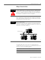
Throughout this manual we use notes to make you aware of safety
considerations.
WARNING
IMPORTANT
ATTENTION
Identifies information about practices or circumstances
that can cause an explosion in a hazardous environment,
which may lead to personal injury or death, property
damage, or economic loss.
Identifies information that is critical for successful
application and understanding of the product.
Identifies information about practices or circumstances
that can lead to personal injury or death, property
damage, or economic loss. Attentions help you:
• identify a hazard
• avoid a hazard
• recognize the consequence
SHOCK HAZARD
Labels may be located on or inside the drive to alert
people that dangerous voltage may be present.
BURN HAZARD
Labels may be located on or inside the drive to alert
people that surfaces may be dangerous temperatures.
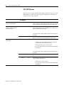
Summary of Changes
Introduction
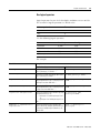
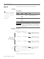
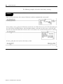
This release of this document contains new and updated information.
To find new and updated information, look for change bars, as shown
next to this paragraph.
Updated Information
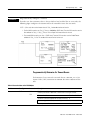
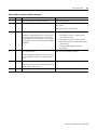
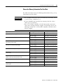
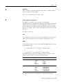
The document contains the following changes:
Section:
Change:
Page:
Describe a User-Defined Data Type
Use the pass through of descriptions to reduce the time it takes to
document a project.
3-21
Prioritize Periodic and Event Tasks
Corrections to the example of how tasks interrupt one another
4-7
Choose the Trigger for an Event Task
Addition of consumed tag trigger for CompactLogix, FlexLogix, and
DriveLogix controllers
4-20
Export/Import Ladder Logic
Create a file that contains the ladder logic, tags, data types, parameter
values, and documentation for a specific function, operation, or process.
8-14
Develop a Fault Routine
• Integration of the Power-Up Handler information into this section.
This was done to clarify when a major fault occurs during
power-up and how to handle it, if required.
15-1
• Clarification regarding a fault due to a mode change
Clear a Major Fault During Prescan
Some controllers now automatically clear a fault that is due an array
subscript that is beyond the range of the array (out of range) during
prescan.
15-8
Create a User-Defined Major Fault
If you create a user-defined major fault, use a value between 990 to 999
for the fault code. These codes are reserved for user-defined faults.
15-13
Minor Fault Codes
Correction to missing fault codes for the GSV/SSV instructions
16-4
Choose a Controller That Has Nonvolatile
Memory
Addition of the following controllers:
17-3
• CompactLogix5331
• CompactLogix5332E
• CompactLogix5335CR
• ControlLogix5560M03SE
• DriveLogix5730
1
Estimate Memory Information Offline
Estimate the free and used memory of a controller while still offline
19-2
View Run Time Memory Information
View the free and used memory of a controller while the controller is
running
19-3
Publication 1756-PM001G-EN-P - March 2004
Summary of Changes
2
Publication 1756-PM001G-EN-P - March 2004
Preface
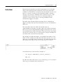
Purpose of this Manual
This manual guides the development of projects for Logix5000™
controllers. It provides step-by-step procedures on how to perform
the following tasks, which are common to all Logix5000 controllers:
•
•
•
•
Organize Tasks, Programs, and Routines
Organize Tags
Design a Sequential Function Chart
Program Routines using ladder logic, function block diagram,
sequential function chart, or structured text programming
languages
• Communicate with Other Controllers
• Communicate and Process ASCII Information
• Handle Faults
The term Logix5000 controller refers to any controller that is based on
the Logix5000 operating system, such as:
• CompactLogix™ controllers
• ControlLogix® controllers
• DriveLogix™ controllers
• FlexLogix™ controllers
• SoftLogix5800™ controllers
This manual works together with user manuals for your specific type
of controller. The user manuals cover tasks such as:
• Place and configure I/O
• Communicate with devices over various networks
• Maintain the battery
Who Should Use this
Manual
This manual is intended for those individuals who program
applications that use Logix5000 controllers, such as:
•
•
•
•
1
software engineers
control engineers
application engineers
instrumentation technicians
Publication 1756-PM001G-EN-P - March 2004
Preface
2
When to Use this Manual
Use this manual when you perform these actions:
• develop the basic code for your application
• modify an existing application
• perform isolated tests of your application
As you integrate your application with the I/0 devices, controllers, and
networks in your system:
• Refer to the user manual for your specific type of controller.
• Use this manual as a reference, when needed.
How to Use this Manual
This manual is divided into the basic tasks that you perform while
programming a Logix5000 controller.
• Each chapter covers a task.
• The tasks are organized in the sequence that you will typically
perform them.
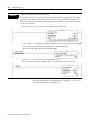
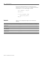
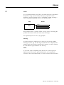
As you use this manual, you will see some terms that are formatted
differently from the rest of the text:
Text that is:
Identifies:
For example:
Italic
the actual name of an item that you Right-click User-Defined …
see on your screen or in an example
Right-click on the item that is named
User-Defined.
bold
an entry in the “Glossary”
If you want additional information, refer
to name in the “Glossary.”
Type a name …
Means:
If you are viewing the PDF file of the
manual, click name to jump to the
glossary entry.
courier
information that you must supply
based on your application (a
variable)
enclosed in brackets a keyboard key
Publication 1756-PM001G-EN-P - March 2004
Right-click
name_of_program …
You must identify the specific program in
your application. Typically, it is a name or
variable that you have defined.
Press [Enter].
Press the Enter key.
Table of Contents
Chapter 1
Getting Started
Using This Chapter . . . . . . . . . . . . . . . . . . . . . . . . . . . . . . 1-1
Create a Project. . . . . . . . . . . . . . . . . . . . . . . . . . . . . . . . . 1-1
Create a Project . . . . . . . . . . . . . . . . . . . . . . . . . . . . . . 1-2
Configure a Project . . . . . . . . . . . . . . . . . . . . . . . . . . . 1-3
Explore a Project. . . . . . . . . . . . . . . . . . . . . . . . . . . . . . . . 1-4
Controller Organizer . . . . . . . . . . . . . . . . . . . . . . . . . . 1-6
Create Routines. . . . . . . . . . . . . . . . . . . . . . . . . . . . . . . . . 1-7
Define a Routine for Each Section of Your Machine or Process
1-7
Identify the Programming Languages That Are Installed. 1-7
Choose a Programming Language for Each Section . . . . 1-8
Divide Each Routine Into More Meaningful Increments . 1-9
Create a Routine . . . . . . . . . . . . . . . . . . . . . . . . . . . . . 1-10
Open a Routine . . . . . . . . . . . . . . . . . . . . . . . . . . . . . . 1-11
Verify a Project . . . . . . . . . . . . . . . . . . . . . . . . . . . . . . . . . 1-12
Save a Project . . . . . . . . . . . . . . . . . . . . . . . . . . . . . . . . . . 1-12
Configure a Communication Driver . . . . . . . . . . . . . . . . . . 1-13
Download a Project to the Controller . . . . . . . . . . . . . . . . . 1-14
Select a Mode for the Controller . . . . . . . . . . . . . . . . . . . . 1-16
Manually Clear a Major Fault . . . . . . . . . . . . . . . . . . . . . . . 1-17
Configure the Execution of a Task . . . . . . . . . . . . . . . . . . . 1-18
Configure a Task . . . . . . . . . . . . . . . . . . . . . . . . . . . . . 1-19
Create Multiple Programs . . . . . . . . . . . . . . . . . . . . . . . . . 1-20
Create a Program . . . . . . . . . . . . . . . . . . . . . . . . . . . . . 1-20
Configure a Program . . . . . . . . . . . . . . . . . . . . . . . . . . 1-21
Access Status Information . . . . . . . . . . . . . . . . . . . . . . . . . 1-22
Monitor Status Flags . . . . . . . . . . . . . . . . . . . . . . . . . . . 1-22
Get and Set System Data . . . . . . . . . . . . . . . . . . . . . . . 1-23
Adjust the System Overhead Time Slice . . . . . . . . . . . . . . . 1-26
Adjust the System Overhead Time Slice . . . . . . . . . . . . 1-28
View Scan Time . . . . . . . . . . . . . . . . . . . . . . . . . . . . . . . . 1-29
View Task Scan Time. . . . . . . . . . . . . . . . . . . . . . . . . . 1-29
View Program Scan Time . . . . . . . . . . . . . . . . . . . . . . . 1-30
Adjust the Watchdog Time . . . . . . . . . . . . . . . . . . . . . . . . 1-31
Adjust the Watchdog Timer for a Task . . . . . . . . . . . . . 1-31
Chapter 2
Communicate with I/O
i
Using This Chapter . . . . . . . .
Configure an I/O Module . . .
Requested Packet Interval
Communication Format . .
Electronic Keying. . . . . . .
Address I/O Data . . . . . . . . .
Buffer I/O. . . . . . . . . . . . . . .
When to Buffer I/O . . . . .
.
.
.
.
.
.
.
.
.
.
.
.
.
.
.
.
.
.
.
.
.
.
.
.
.
.
.
.
.
.
.
.
.
.
.
.
.
.
.
.
.
.
.
.
.
.
.
.
.
.
.
.
.
.
.
.
.
.
.
.
.
.
.
.
.
.
.
.
.
.
.
.
.
.
.
.
.
.
.
.
.
.
.
.
.
.
.
.
.
.
.
.
.
.
.
.
.
.
.
.
.
.
.
.
.
.
.
.
.
.
.
.
.
.
.
.
.
.
.
.
.
.
.
.
.
.
.
.
.
.
.
.
.
.
.
.
.
.
.
.
.
.
.
.
.
.
.
.
.
.
.
.
.
.
.
.
.
.
.
.
.
.
.
.
.
.
.
.
.
.
.
.
.
.
.
.
2-1
2-1
2-2
2-3
2-6
2-7
2-8
2-8
Publication 1756-PM001G-EN-P - March 2004
Table of Contents
ii
Buffer I/O . . . . . . . . . . . . . . . . . . . . . . . . . . . . . . . . . . 2-8
Chapter 3
Organize Tags
Using this Chapter. . . . . . . . . . . . . . . . . . . . . . . . . . . . . . .
Defining Tags . . . . . . . . . . . . . . . . . . . . . . . . . . . . . . . . . .
Tag Type. . . . . . . . . . . . . . . . . . . . . . . . . . . . . . . . . . .
Data Type . . . . . . . . . . . . . . . . . . . . . . . . . . . . . . . . . .
Scope . . . . . . . . . . . . . . . . . . . . . . . . . . . . . . . . . . . . .
Guidelines for Tags . . . . . . . . . . . . . . . . . . . . . . . . . . . . . .
Create a Tag . . . . . . . . . . . . . . . . . . . . . . . . . . . . . . . . . . .
Create a Tag Using a Tags Window . . . . . . . . . . . . . . .
Create Tags Using Microsoft® Excel . . . . . . . . . . . . . . .
Create an Array . . . . . . . . . . . . . . . . . . . . . . . . . . . . . . . . .
Create an Array . . . . . . . . . . . . . . . . . . . . . . . . . . . . . .
Create a User-Defined Data Type. . . . . . . . . . . . . . . . . . . .
Guidelines for User-Defined Data Types . . . . . . . . . . . .
Create a User-Defined Data Type . . . . . . . . . . . . . . . . .
Describe a User-Defined Data Type . . . . . . . . . . . . . . . . . .
Turn Pass-Through and Append Descriptions On or Off
Paste a Pass-Through Description . . . . . . . . . . . . . . . . .
Address Tag Data . . . . . . . . . . . . . . . . . . . . . . . . . . . . . . .
Assign Alias Tags . . . . . . . . . . . . . . . . . . . . . . . . . . . . . . .
Display Alias Information . . . . . . . . . . . . . . . . . . . . . . .
Assign an Alias . . . . . . . . . . . . . . . . . . . . . . . . . . . . . .
Assign an Indirect Address . . . . . . . . . . . . . . . . . . . . . . . .
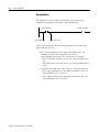
Expressions . . . . . . . . . . . . . . . . . . . . . . . . . . . . . . . . .
3-1
3-1
3-2
3-3
3-5
3-7
3-9
3-9
3-10
3-13
3-16
3-17
3-19
3-19
3-21
3-22
3-22
3-23
3-24
3-25
3-26
3-27
3-29
Chapter 4
Manage Multiple Tasks
Publication 1756-PM001G-EN-P - March 2004
Using This Chapter . . . . . . . . . . . . . . . . . . . . . . . . . . .
Select the Controller Tasks . . . . . . . . . . . . . . . . . . . . .
Use Caution in the Number of Tasks That You Use .
Prioritize Periodic and Event Tasks . . . . . . . . . . . . . . .
Additional Considerations. . . . . . . . . . . . . . . . . . . .
Leave Enough Time for Unscheduled Communication .
Avoid Overlaps . . . . . . . . . . . . . . . . . . . . . . . . . . . . . .
Manually Check for Overlaps . . . . . . . . . . . . . . . . .
Programmatically Check for Overlaps . . . . . . . . . . .
Configure Output Processing for a Task . . . . . . . . . . . .
Manually Configure Output Processing . . . . . . . . . .
Programmatically Configure Output Processing . . . .
Inhibit a Task . . . . . . . . . . . . . . . . . . . . . . . . . . . . . . .
Manually Inhibit or Uninhibit a Task. . . . . . . . . . . .
Programmatically Inhibit or Uninhibit a Task. . . . . .
Choose the Trigger for an Event Task . . . . . . . . . . . . .
Using the Module Input Data State Change Trigger. . . .
.
.
.
.
.
.
.
.
.
.
.
.
.
.
.
.
.
.
.
.
.
.
.
.
.
.
.
.
.
.
.
.
.
.
.
.
.
.
.
.
.
.
.
.
.
.
.
.
.
.
.
4-1
4-2
4-5
4-5
4-6
4-8
4-9
4-10
4-11
4-13
4-15
4-16
4-17
4-17
4-19
4-20
4-22
Table of Contents
How an I/O Module Triggers an Event Task . . . . . . .
Make Sure Your Module Can Trigger an Event Task .
Checklist for an Input Event Task . . . . . . . . . . . . . . .
Estimate Throughput . . . . . . . . . . . . . . . . . . . . . . . .
Estimate Throughput . . . . . . . . . . . . . . . . . . . . . . . .
Additional Considerations. . . . . . . . . . . . . . . . . . . . .
Using the Motion Group Trigger . . . . . . . . . . . . . . . . . .
Checklist for a Motion Group Task . . . . . . . . . . . . . .
Using the Axis Registration Trigger . . . . . . . . . . . . . . . .
Checklist for an Axis Registration Task . . . . . . . . . . .
Using the Axis Watch Trigger . . . . . . . . . . . . . . . . . . . .
Checklist for an Axis Watch Task . . . . . . . . . . . . . . .
Using the Consumed Tag Trigger. . . . . . . . . . . . . . . . . .
Maintain the Integrity of Data . . . . . . . . . . . . . . . . . .
Synchronize Multiple Controllers . . . . . . . . . . . . . . .
Checklist for the Producer Controller . . . . . . . . . . . .
Checklist for the Consumer Controller . . . . . . . . . . .
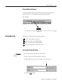
Producer Controller . . . . . . . . . . . . . . . . . . . . . . . . .
Consumer Controller . . . . . . . . . . . . . . . . . . . . . . . .
Using the EVENT Instruction Trigger . . . . . . . . . . . . . . .
Programmatically Determine if an EVENT Instruction
Triggered a Task . . . . . . . . . . . . . . . . . . . . . . . . . . .
Checklist for an EVENT Instruction Task . . . . . . . . . .
Create a Task . . . . . . . . . . . . . . . . . . . . . . . . . . . . . . . .
Create an Event Task . . . . . . . . . . . . . . . . . . . . . . . .
Create a Periodic Task . . . . . . . . . . . . . . . . . . . . . . .
Define a Timeout Value for an Event Task . . . . . . . . . . .
Assign a Timeout Value to an Event Task . . . . . . . . .
Programmatically Configure a Timeout . . . . . . . . . . .
Programmatically Determine if a Timeout Occurs . . .
iii
.
.
.
.
.
.
.
.
.
.
.
.
.
.
.
.
.
.
.
.
.
.
.
.
.
.
.
.
.
.
.
.
.
.
.
.
.
.
.
.
4-22
4-25
4-26
4-28
4-30
4-31
4-32
4-33
4-34
4-35
4-38
4-39
4-42
4-44
4-45
4-46
4-47
4-48
4-49
4-50
.
.
.
.
.
.
.
.
.
.
.
.
.
.
.
.
.
.
4-51
4-51
4-53
4-53
4-54
4-55
4-55
4-56
4-57
.
.
.
.
.
.
.
.
.
.
.
.
.
.
.
.
.
.
.
.
.
.
.
.
.
.
.
.
5-1
5-1
5-2
5-4
5-5
5-6
5-6
5-7
5-8
5-12
5-12
5-14
5-15
5-16
Chapter 5
Design a Sequential Function
Chart
When to Use This Procedure . . . . . .
How to Use This Procedure. . . . . . .
What is a Sequential Function Chart?
How to Design an SFC: Overview . .
Define the Tasks . . . . . . . . . . . . . . .
Choose How to Execute the SFC . . .
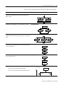
Define the Steps of the Process . . . .
Follow These Guidelines . . . . . .
SFC_STEP Structure . . . . . . . . . .
Organize the Steps . . . . . . . . . . . . .
Overview . . . . . . . . . . . . . . . . .
Sequence. . . . . . . . . . . . . . . . . .
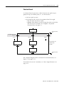
Selection Branch . . . . . . . . . . . .
Simultaneous Branch . . . . . . . . .
.
.
.
.
.
.
.
.
.
.
.
.
.
.
.
.
.
.
.
.
.
.
.
.
.
.
.
.
.
.
.
.
.
.
.
.
.
.
.
.
.
.
.
.
.
.
.
.
.
.
.
.
.
.
.
.
.
.
.
.
.
.
.
.
.
.
.
.
.
.
.
.
.
.
.
.
.
.
.
.
.
.
.
.
.
.
.
.
.
.
.
.
.
.
.
.
.
.
.
.
.
.
.
.
.
.
.
.
.
.
.
.
.
.
.
.
.
.
.
.
.
.
.
.
.
.
.
.
.
.
.
.
.
.
.
.
.
.
.
.
.
.
.
.
.
.
.
.
.
.
.
.
.
.
.
.
.
.
.
.
.
.
.
.
.
.
.
.
.
.
.
.
.
.
.
.
.
.
.
.
.
.
.
.
.
.
.
.
.
.
.
.
.
.
.
.
.
.
.
.
.
.
.
.
.
.
.
.
.
.
Publication 1756-PM001G-EN-P - March 2004
Table of Contents
iv
Wire to a Previous Step . . . . . . . . . . . . . . . . . . . .
Add Actions for Each Step . . . . . . . . . . . . . . . . . . . . .
How Do You Want to Use the Action? . . . . . . . . .
Use a Non-Boolean Action . . . . . . . . . . . . . . . . . .
Use a Boolean Action. . . . . . . . . . . . . . . . . . . . . .
SFC_ACTION Structure. . . . . . . . . . . . . . . . . . . . .
Describe Each Action in Pseudocode . . . . . . . . . . . . .
Choose a Qualifier for an Action . . . . . . . . . . . . . . . .
Define the Transition Conditions . . . . . . . . . . . . . . . .
Transition Tag . . . . . . . . . . . . . . . . . . . . . . . . . . .
How Do You Want to Program the Transition? . . .
Use a BOOL Expression . . . . . . . . . . . . . . . . . . . .
Call a Subroutine . . . . . . . . . . . . . . . . . . . . . . . . .
Transition After a Specified Time . . . . . . . . . . . . . . . .
Turn Off a Device at the End of a Step . . . . . . . . . . .
Choose a Last Scan Option. . . . . . . . . . . . . . . . . .
Use the Don’t Scan Option . . . . . . . . . . . . . . . . . .
Use the Programmatic Reset Option . . . . . . . . . . .
Use the Automatic Reset Option . . . . . . . . . . . . . .
Keep Something On From Step-to-Step . . . . . . . . . . .
How Do You Want to Control the Device? . . . . . .
Use a Simultaneous Branch . . . . . . . . . . . . . . . . .
Store and Reset an Action. . . . . . . . . . . . . . . . . . .
Use One Large Step . . . . . . . . . . . . . . . . . . . . . . .
End the SFC . . . . . . . . . . . . . . . . . . . . . . . . . . . . . . .
At the End of the SFC, What Do You Want to Do?.
Use a Stop Element . . . . . . . . . . . . . . . . . . . . . . .
Restart (Reset) the SFC . . . . . . . . . . . . . . . . . . . . .
SFC_STOP Structure . . . . . . . . . . . . . . . . . . . . . . .
Nest an SFC . . . . . . . . . . . . . . . . . . . . . . . . . . . . . . .
Pass Parameters . . . . . . . . . . . . . . . . . . . . . . . . . .
Configure When to Return to the OS/JSR . . . . . . . . . .
Pause or Reset an SFC . . . . . . . . . . . . . . . . . . . . . . . .
Execution Diagrams . . . . . . . . . . . . . . . . . . . . . . . . .
.
.
.
.
.
.
.
.
.
.
.
.
.
.
.
.
.
.
.
.
.
.
.
.
.
.
.
.
.
.
.
.
.
.
.
.
.
.
.
.
.
.
.
.
.
.
.
.
.
.
.
.
.
.
.
.
.
.
.
.
.
.
.
.
.
.
.
.
.
.
.
.
.
.
.
.
.
.
.
.
.
.
.
.
.
.
.
.
.
.
.
.
.
.
.
.
.
.
.
.
.
.
.
.
.
.
.
.
.
.
.
.
.
.
.
.
.
.
.
.
.
.
.
.
.
.
.
.
.
.
.
.
.
.
.
.
5-17
5-18
5-18
5-18
5-20
5-20
5-21
5-23
5-24
5-26
5-26
5-26
5-27
5-28
5-32
5-32
5-34
5-35
5-38
5-40
5-40
5-41
5-42
5-44
5-45
5-45
5-45
5-46
5-47
5-49
5-50
5-50
5-51
5-51
.
.
.
.
.
.
.
.
.
.
.
.
.
.
.
.
.
.
.
.
.
.
.
.
.
.
.
.
.
.
.
.
.
.
.
.
.
.
.
.
6-1
6-1
6-2
6-3
6-3
6-4
6-4
6-5
6-5
6-5
Chapter 6
Program a Sequential Function
Chart
Publication 1756-PM001G-EN-P - March 2004
When to Use This Procedure . . . . . . . . . . . . .
Before You Use This Procedure. . . . . . . . . . .
How to Use This Procedure. . . . . . . . . . . . . .
Add an SFC Element . . . . . . . . . . . . . . . . . . .
Add and Manually Connect Elements . . . .
Add and Automatically Connect Elements .
Drag and Drop Elements . . . . . . . . . . . . .
Create a Simultaneous Branch . . . . . . . . . . . .
Start a Simultaneous Branch . . . . . . . . . . .
End a Simultaneous Branch . . . . . . . . . . .
.
.
.
.
.
.
.
.
.
.
.
.
.
.
.
.
.
.
.
.
.
.
.
.
.
.
.
.
.
.
.
.
.
.
.
.
.
.
.
.
.
.
.
.
.
.
.
.
.
.
.
.
.
.
.
.
.
.
.
.
Table of Contents
Create a Selection Branch . . . . . . . . . . . . . . . .
Start a Selection Branch . . . . . . . . . . . . . . .
End a Selection Branch . . . . . . . . . . . . . . .
Set the Priorities of a Selection Branch . . . . . . .
Return to a Previous Step . . . . . . . . . . . . . . . .
Connect a Wire to the Step. . . . . . . . . . . . .
Hide a Wire. . . . . . . . . . . . . . . . . . . . . . . .
Show a Hidden Wire . . . . . . . . . . . . . . . . .
Rename a Step . . . . . . . . . . . . . . . . . . . . . . . .
Configure a Step . . . . . . . . . . . . . . . . . . . . . . .
Assign the Preset Time for a Step . . . . . . . .
Configure Alarms for a Step . . . . . . . . . . . .
Use an Expression to Calculate a Time . . . .
Rename a Transition . . . . . . . . . . . . . . . . . . . .
Program a Transition . . . . . . . . . . . . . . . . . . . .
Enter a BOOL Expression. . . . . . . . . . . . . .
Call a Subroutine . . . . . . . . . . . . . . . . . . . .
Add an Action. . . . . . . . . . . . . . . . . . . . . . . . .
Rename an Action. . . . . . . . . . . . . . . . . . . . . .
Configure an Action . . . . . . . . . . . . . . . . . . . .
Change the Qualifier of an Action. . . . . . . .
Calculate a Preset Time at Runtime . . . . . . .
Mark an Action as a Boolean Action . . . . . .
Program an Action . . . . . . . . . . . . . . . . . . . . .
Enter Structured Text . . . . . . . . . . . . . . . . .
Call a Subroutine . . . . . . . . . . . . . . . . . . . .
Assign the Execution Order of Actions . . . . . . .
Document the SFC . . . . . . . . . . . . . . . . . . . . .
Add Structured Text Comments . . . . . . . . .
Add a Tag Description . . . . . . . . . . . . . . . .
Add a Text Box . . . . . . . . . . . . . . . . . . . . .
Show or Hide Text Boxes or Tag Descriptions .
Show or Hide Text Boxes or Descriptions. .
Hide an Individual Tag Description . . . . . .
Configure the Execution of the SFC . . . . . . . . .
Verify the Routine . . . . . . . . . . . . . . . . . . . . . .
v
.
.
.
.
.
.
.
.
.
.
.
.
.
.
.
.
.
.
.
.
.
.
.
.
.
.
.
.
.
.
.
.
.
.
.
.
.
.
.
.
.
.
.
.
.
.
.
.
.
.
.
.
.
.
.
.
.
.
.
.
.
.
.
.
.
.
.
.
.
.
.
.
.
.
.
.
.
.
.
.
.
.
.
.
.
.
.
.
.
.
.
.
.
.
.
.
.
.
.
.
.
.
.
.
.
.
.
.
.
.
.
.
.
.
.
.
.
.
.
.
.
.
.
.
.
.
.
.
.
.
.
.
.
.
.
.
.
.
.
.
.
.
.
.
.
.
.
.
.
.
.
.
.
.
.
.
.
.
.
.
.
.
.
.
.
.
.
.
.
.
.
.
.
.
.
.
.
.
.
.
.
.
.
.
.
.
.
.
.
.
.
.
.
.
.
.
.
.
.
.
.
.
.
.
.
.
.
.
.
.
.
.
.
.
.
.
.
.
.
.
.
.
.
.
.
.
.
.
.
.
.
.
.
.
.
.
.
.
.
.
.
.
.
.
.
.
.
.
.
.
.
.
.
.
.
.
.
.
.
.
.
.
.
.
.
.
.
.
.
.
.
.
.
.
.
.
.
.
.
.
.
.
.
.
.
.
.
.
.
.
.
.
.
.
.
.
.
.
.
.
.
.
.
.
.
.
.
.
.
.
.
.
.
.
.
.
.
.
.
.
.
.
.
.
6-6
6-6
6-7
6-8
6-9
6-9
6-10
6-10
6-11
6-11
6-11
6-12
6-12
6-14
6-14
6-14
6-15
6-16
6-16
6-17
6-17
6-18
6-19
6-19
6-19
6-21
6-22
6-23
6-23
6-24
6-25
6-26
6-26
6-27
6-28
6-29
.
.
.
.
.
.
.
.
.
.
.
.
.
.
.
.
.
.
.
.
.
.
.
.
.
.
.
.
.
.
.
.
.
.
.
.
.
.
.
.
.
.
.
.
.
.
.
.
.
.
.
.
.
.
.
.
.
.
.
.
.
.
.
.
.
.
.
.
.
.
.
.
7-1
7-1
7-2
7-3
7-4
7-4
7-6
7-7
Chapter 7
Program Structured Text
When to Use This Chapter. . . . . . . . . . . . .
Structured Text Syntax. . . . . . . . . . . . . . . .
Assignments . . . . . . . . . . . . . . . . . . . . . . .
Specify a non-retentive assignment . . . .
Assign an ASCII character to a string. . .
Expressions . . . . . . . . . . . . . . . . . . . . . . .
Use arithmetic operators and functions .
Use relational operators . . . . . . . . . . . .
.
.
.
.
.
.
.
.
.
.
.
.
.
.
.
.
.
.
.
.
.
.
.
.
Publication 1756-PM001G-EN-P - March 2004
Table of Contents
vi
Use logical operators . . . . . . . . . .
Use bitwise operators. . . . . . . . . .
Determine the order of execution.
Instructions. . . . . . . . . . . . . . . . . . . .
Constructs. . . . . . . . . . . . . . . . . . . . .
IF...THEN . . . . . . . . . . . . . . . . . . . . .
CASE...OF . . . . . . . . . . . . . . . . . . . . .
FOR…DO. . . . . . . . . . . . . . . . . . . . .
WHILE…DO. . . . . . . . . . . . . . . . . . .
REPEAT…UNTIL . . . . . . . . . . . . . . . .
Comments . . . . . . . . . . . . . . . . . . . .
.
.
.
.
.
.
.
.
.
.
.
.
.
.
.
.
.
.
.
.
.
.
.
.
.
.
.
.
.
.
.
.
.
.
.
.
.
.
.
.
.
.
.
.
.
.
.
.
.
.
.
.
.
.
.
.
.
.
.
.
.
.
.
.
.
.
.
.
.
.
.
.
.
.
.
.
.
.
.
.
.
.
.
.
.
.
.
.
.
.
.
.
.
.
.
.
.
.
.
.
.
.
.
.
.
.
.
.
.
.
.
.
.
.
.
.
.
.
.
.
.
.
.
.
.
.
.
.
.
.
.
.
.
.
.
.
.
.
.
.
.
.
.
.
.
.
.
.
.
.
.
.
.
.
.
.
.
.
.
.
.
.
.
.
.
.
.
.
.
.
.
.
.
.
.
.
7-9
7-10
7-10
7-11
7-12
7-13
7-16
7-19
7-22
7-25
7-28
When to Use This Procedure . . . . . . . . . . . . . .
Before You Use This Procedure. . . . . . . . . . . .
How to Use This Procedure. . . . . . . . . . . . . . .
Definitions . . . . . . . . . . . . . . . . . . . . . . . . . . .
Instruction . . . . . . . . . . . . . . . . . . . . . . . . .
Branch . . . . . . . . . . . . . . . . . . . . . . . . . . .
Rung Condition . . . . . . . . . . . . . . . . . . . . .
Write Ladder Logic . . . . . . . . . . . . . . . . . . . . .
Choose the Required Instructions . . . . . . . .
Arrange the Input Instructions . . . . . . . . . .
Arrange the Output Instructions . . . . . . . . .
Choose a Tag Name for an Operand. . . . . .
Enter Ladder Logic . . . . . . . . . . . . . . . . . . . . .
Append an Element to the Cursor Location .
Drag and Drop an Element . . . . . . . . . . . .
Assign Operands. . . . . . . . . . . . . . . . . . . . . . .
Create and Assign a New Tag. . . . . . . . . . .
Choose a Name or an Existing Tag . . . . . . .
Drag a Tag From the Tags Window . . . . . .
Assign an Immediate (Constant) Value . . . .
Export/Import Ladder Logic. . . . . . . . . . . . . . .
When You Import Rungs… . . . . . . . . . . . .
Export Rungs. . . . . . . . . . . . . . . . . . . . . . .
Import Rungs. . . . . . . . . . . . . . . . . . . . . . .
Check Alias Tags . . . . . . . . . . . . . . . . . . . .
Verify the Routine . . . . . . . . . . . . . . . . . . . . . .
.
.
.
.
.
.
.
.
.
.
.
.
.
.
.
.
.
.
.
.
.
.
.
.
.
.
.
.
.
.
.
.
.
.
.
.
.
.
.
.
.
.
.
.
.
.
.
.
.
.
.
.
.
.
.
.
.
.
.
.
.
.
.
.
.
.
.
.
.
.
.
.
.
.
.
.
.
.
.
.
.
.
.
.
.
.
.
.
.
.
.
.
.
.
.
.
.
.
.
.
.
.
.
.
.
.
.
.
.
.
.
.
.
.
.
.
.
.
.
.
.
.
.
.
.
.
.
.
.
.
.
.
.
.
.
.
.
.
.
.
.
.
.
.
.
.
.
.
.
.
.
.
.
.
.
.
.
.
.
.
.
.
.
.
.
.
.
.
.
.
.
.
.
.
.
.
.
.
.
.
.
.
.
.
.
.
.
.
.
.
.
.
.
.
.
.
.
.
.
.
.
.
.
.
.
.
.
.
.
.
.
.
.
.
.
.
.
.
.
.
.
.
.
.
.
.
.
.
.
.
.
.
.
.
8-1
8-1
8-1
8-2
8-2
8-2
8-4
8-5
8-5
8-6
8-7
8-8
8-10
8-10
8-11
8-11
8-11
8-13
8-13
8-13
8-14
8-14
8-15
8-16
8-16
8-17
.
.
.
.
.
.
.
.
.
.
.
.
.
.
.
.
.
.
.
.
.
.
.
.
.
.
.
.
.
.
.
.
.
.
.
.
9-1
9-1
9-1
9-2
Chapter 8
Program Ladder Logic
Chapter 9
Program a Function Block
Diagram
Publication 1756-PM001G-EN-P - March 2004
When to Use This Procedure . . . . .
Before You Use This Procedure. . .
How to Use This Procedure. . . . . .
Identify the Sheets for the Routine .
.
.
.
.
.
.
.
.
.
.
.
.
.
.
.
.
.
.
.
.
.
.
.
.
.
.
.
.
.
.
.
.
.
.
.
.
Table of Contents
Choose the Function Block Elements . . . . . . . . . . . . . . . .
Choose a Tag Name for an Element. . . . . . . . . . . . . . . . .
Define the Order of Execution. . . . . . . . . . . . . . . . . . . . .
Data Latching . . . . . . . . . . . . . . . . . . . . . . . . . . . . . .
Order of Execution . . . . . . . . . . . . . . . . . . . . . . . . . .
Resolve a Loop . . . . . . . . . . . . . . . . . . . . . . . . . . . . .
Resolve Data Flow Between Two Blocks . . . . . . . . . .
Create a One Scan Delay . . . . . . . . . . . . . . . . . . . . . .
Summary . . . . . . . . . . . . . . . . . . . . . . . . . . . . . . . . . .
Identify any Connectors . . . . . . . . . . . . . . . . . . . . . . . . .
Define Program/Operator Control . . . . . . . . . . . . . . . . . .
Add a Sheet . . . . . . . . . . . . . . . . . . . . . . . . . . . . . . . . . .
Add a Function Block Element . . . . . . . . . . . . . . . . . . . .
Connect Elements . . . . . . . . . . . . . . . . . . . . . . . . . . . . . .
Show or Hide a Pin . . . . . . . . . . . . . . . . . . . . . . . . . .
Wire Elements Together . . . . . . . . . . . . . . . . . . . . . . .
Mark a Wire with the Assume Data Available Indicator
Assign a Tag . . . . . . . . . . . . . . . . . . . . . . . . . . . . . . . . . .
Create and Assign a New Tag. . . . . . . . . . . . . . . . . . .
Rename the Tag of a Function Block . . . . . . . . . . . . .
Assign an Existing Tag . . . . . . . . . . . . . . . . . . . . . . . .
Assign an Immediate Value (Constant) . . . . . . . . . . . . . . .
Use an IREF. . . . . . . . . . . . . . . . . . . . . . . . . . . . . . . .
Enter a Value in the Tag of a Block . . . . . . . . . . . . . .
Connect Blocks with an OCON and ICON . . . . . . . . . . . .
Add an OCON . . . . . . . . . . . . . . . . . . . . . . . . . . . . . .
Add an ICON. . . . . . . . . . . . . . . . . . . . . . . . . . . . . . .
Verify the Routine . . . . . . . . . . . . . . . . . . . . . . . . . . . . . .
.
.
.
.
.
.
.
.
.
.
.
.
.
.
.
.
.
.
.
.
.
.
.
.
.
.
.
.
vii
9-3
9-4
9-5
9-5
9-7
9-8
9-11
9-12
9-12
9-13
9-14
9-18
9-18
9-20
9-20
9-21
9-21
9-22
9-22
9-23
9-23
9-24
9-24
9-24
9-25
9-25
9-25
9-26
Chapter 10
Communicate with Other Devices Using This Chapter . . . . . . . . . . . . . . . . . . . . . . . . . . . . . . 10-1
Connections . . . . . . . . . . . . . . . . . . . . . . . . . . . . . . . . . . . 10-1
Inhibit a Connection . . . . . . . . . . . . . . . . . . . . . . . . . . 10-2
Manage a Connection Failure . . . . . . . . . . . . . . . . . . . . 10-5
Produce and Consume a Tag . . . . . . . . . . . . . . . . . . . . . . . 10-9
Controllers and Networks that Support Produced/Consumed
Tags . . . . . . . . . . . . . . . . . . . . . . . . . . . . . . . . . . . . . 10-10
Connection Requirements of a Produced or Consumed Tag.
10-10
Organize Tags for Produced or Consumed Data . . . . . 10-12
Adjust for Bandwidth Limitations . . . . . . . . . . . . . . . . 10-13
Produce a Tag . . . . . . . . . . . . . . . . . . . . . . . . . . . . . . 10-14
Consume Data That Is Produced by Another Controller . . . .
10-15
Additional Steps for a PLC-5C Controller . . . . . . . . . . . 10-17
Execute a Message (MSG) Instruction. . . . . . . . . . . . . . . . 10-19
Publication 1756-PM001G-EN-P - March 2004
Table of Contents
viii
Message Queue . . . . . . . . . . . . . . . . . . . . .
Cache List . . . . . . . . . . . . . . . . . . . . . . . . .
Unconnected Buffers . . . . . . . . . . . . . . . . .
Guidelines . . . . . . . . . . . . . . . . . . . . . . . . .
Get or Set the Number of Unconnected Buffers
Get the Number of Unconnected Buffers . .
Set the Number of Unconnected Buffers . . .
Convert Between INTs and DINTs . . . . . . . . . .
.
.
.
.
.
.
.
.
.
.
.
.
.
.
.
.
.
.
.
.
.
.
.
.
.
.
.
.
.
.
.
.
.
.
.
.
.
.
.
.
.
.
.
.
.
.
.
.
.
.
.
.
.
.
.
.
.
.
.
.
.
.
.
.
10-21
10-22
10-23
10-24
10-25
10-25
10-26
10-28
Chapter 11
Produce a Large Array
When to Use this Procedure . . . . . . . . . . . . . . . . . . . . . . . 11-1
Produce a Large Array . . . . . . . . . . . . . . . . . . . . . . . . . . . . 11-2
Chapter 12
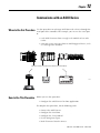
Communicate with an ASCII
Device
When to Use this Procedure . . . .
How to Use This Procedure. . . . .
Connect the ASCII Device . . . . . .
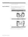
Configure the Serial Port . . . . . . .
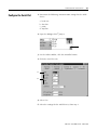
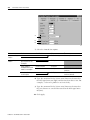
Configure the User Protocol . . . .
Create String Data Types . . . . . . .
Read Characters from the Device .
Send Characters to the Device . . .
Enter ASCII Characters . . . . . . . .
.
.
.
.
.
.
.
.
.
.
.
.
.
.
.
.
.
.
.
.
.
.
.
.
.
.
.
.
.
.
.
.
.
.
.
.
.
.
.
.
.
.
.
.
.
.
.
.
.
.
.
.
.
.
.
.
.
.
.
.
.
.
.
.
.
.
.
.
.
.
.
.
.
.
.
.
.
.
.
.
.
.
.
.
.
.
.
.
.
.
.
.
.
.
.
.
.
.
.
.
.
.
.
.
.
.
.
.
.
.
.
.
.
.
.
.
.
.
.
.
.
.
.
.
.
.
.
.
.
.
.
.
.
.
.
.
.
.
.
.
.
.
.
.
.
.
.
.
.
.
.
.
.
.
.
.
.
.
.
.
.
.
. 12-1
. 12-1
. 12-2
. 12-3
. 12-5
. 12-8
. 12-9
12-14
12-21
When to Use this Procedure . . . . . . . . . . . . .
How to Use this Procedure . . . . . . . . . . . . . .
Extract a Part of a Bar Code. . . . . . . . . . . . . .
Look Up a Bar Code . . . . . . . . . . . . . . . . . . .
Create the PRODUCT_INFO Data Type. . .
Search for the Characters . . . . . . . . . . . . .
Identify the Lane Number. . . . . . . . . . . . .
Reject Bad Characters. . . . . . . . . . . . . . . .
Enter the Product IDs and Lane Numbers .
Check the Bar Code Characters . . . . . . . . . . .
Convert a Value . . . . . . . . . . . . . . . . . . . . . .
Decode an ASCII Message . . . . . . . . . . . . . . .
Build a String . . . . . . . . . . . . . . . . . . . . . . . .
.
.
.
.
.
.
.
.
.
.
.
.
.
.
.
.
.
.
.
.
.
.
.
.
.
.
.
.
.
.
.
.
.
.
.
.
.
.
.
.
.
.
.
.
.
.
.
.
.
.
.
.
.
.
.
.
.
.
.
.
.
.
.
.
.
.
.
.
.
.
.
.
.
.
.
.
.
.
.
.
.
.
.
.
.
.
.
.
.
.
.
.
.
.
.
.
.
.
.
.
.
.
.
.
.
.
.
.
.
.
.
.
.
.
.
.
.
. 13-1
. 13-1
. 13-2
. 13-4
. 13-5
. 13-6
. 13-8
. 13-9
. 13-9
13-10
13-12
13-14
13-18
.
.
.
.
.
.
.
.
.
.
.
.
.
.
.
.
.
.
.
.
.
.
.
.
.
.
.
.
.
.
.
.
.
.
.
.
.
.
.
.
.
.
.
.
.
.
.
.
.
.
Chapter 13
Process ASCII Characters
Chapter 14
Force Logic Elements
Publication 1756-PM001G-EN-P - March 2004
When to Use This Procedure . .
How to Use This Procedure. . .
Precautions. . . . . . . . . . . . . . .
Enable Forces . . . . . . . . . .
Disable or Remove a Force
.
.
.
.
.
.
.
.
.
.
.
.
.
.
.
.
.
.
.
.
.
.
.
.
.
.
.
.
.
.
.
.
.
.
.
.
.
.
.
.
.
.
.
.
.
.
.
.
.
.
.
.
.
.
.
14-1
14-1
14-2
14-2
14-3
Table of Contents
Check Force Status . . . . . . . . . . . . . . . . . . . . .
Online Toolbar . . . . . . . . . . . . . . . . . . . . .
FORCE LED . . . . . . . . . . . . . . . . . . . . . . . .
GSV Instruction . . . . . . . . . . . . . . . . . . . . .
What to Force . . . . . . . . . . . . . . . . . . . . . . . . .
When to Use an I/O Force . . . . . . . . . . . . . . .
Force an Input Value . . . . . . . . . . . . . . . . .
Force an Output Value. . . . . . . . . . . . . . . .
Add an I/O Force . . . . . . . . . . . . . . . . . . . . . .
When to Use Step Through . . . . . . . . . . . . . . .
Step Through a Transition or a Force of a Path.
When to Use an SFC Force . . . . . . . . . . . . . . .
Force a Transition . . . . . . . . . . . . . . . . . . .
Force a Simultaneous Path . . . . . . . . . . . . .
Add an SFC Force . . . . . . . . . . . . . . . . . . . . . .
Remove or Disable Forces . . . . . . . . . . . . . . . .
Remove an Individual Force. . . . . . . . . . . .
Disable All I/O Forces . . . . . . . . . . . . . . . .
Remove All I/O Forces. . . . . . . . . . . . . . . .
Disable All SFC Forces . . . . . . . . . . . . . . . .
Remove All SFC Forces . . . . . . . . . . . . . . .
.
.
.
.
.
.
.
.
.
.
.
.
.
.
.
.
.
.
.
.
.
.
.
.
.
.
.
.
.
.
.
.
.
.
.
.
.
.
.
.
.
.
.
.
.
.
.
.
.
.
.
.
.
.
.
.
.
.
.
.
.
.
.
ix
.
.
.
.
.
.
.
.
.
.
.
.
.
.
.
.
.
.
.
.
.
.
.
.
.
.
.
.
.
.
.
.
.
.
.
.
.
.
.
.
.
.
.
.
.
.
.
.
.
.
.
.
.
.
.
.
.
.
.
.
.
.
.
.
.
.
.
.
.
.
.
.
.
.
.
.
.
.
.
.
.
.
.
.
.
.
.
.
.
.
.
.
.
.
.
.
.
.
.
.
.
.
.
.
.
. 14-4
. 14-4
. 14-5
. 14-5
. 14-6
. 14-6
. 14-7
. 14-7
. 14-8
. 14-9
. 14-9
. 14-9
. 14-9
14-11
14-12
14-13
14-13
14-14
14-14
14-14
14-14
Using this Chapter. . . . . . . . . . . . . . . . . . . . . . . . . .
Develop a Fault Routine . . . . . . . . . . . . . . . . . . . . .
Choose Where to Place the Fault Routine . . . . . .
Create a Fault Routine for a Program . . . . . . . . .
Create a Routine for the Controller Fault Handler
Create a Routine for the Power-Up Handler . . . .
Programmatically Clear a Major Fault . . . . . . . . . . . .
Create a Data Type to Store Fault Information. . .
Get the Fault Type and Code . . . . . . . . . . . . . . .
Check for a Specific Fault. . . . . . . . . . . . . . . . . .
Clear the Fault . . . . . . . . . . . . . . . . . . . . . . . . . .
Clear a Major Fault During Prescan . . . . . . . . . . . . .
Identify When the Controller is in Prescan . . . . .
Get the Fault Type and Code . . . . . . . . . . . . . . .
Check for a Specific Fault. . . . . . . . . . . . . . . . . .
Clear the Fault . . . . . . . . . . . . . . . . . . . . . . . . . .
Test a Fault Routine . . . . . . . . . . . . . . . . . . . . . . . .
Create a User-Defined Major Fault . . . . . . . . . . . . . .
Create a Fault Routine for the Program . . . . . . . .
Configure the Program to Use the Fault Routine .
Jump to the Fault Routine . . . . . . . . . . . . . . . . .
Major Fault Codes . . . . . . . . . . . . . . . . . . . . . . . . . .
.
.
.
.
.
.
.
.
.
.
.
.
.
.
.
.
.
.
.
.
.
.
.
.
.
.
.
.
.
.
.
.
.
.
.
.
.
.
.
.
.
.
.
.
.
.
.
.
.
.
.
.
.
.
.
.
.
.
.
.
.
.
.
.
.
.
.
.
.
.
.
.
.
.
.
.
.
.
.
.
.
.
.
.
.
.
.
.
. 15-1
. 15-1
. 15-2
. 15-2
. 15-3
. 15-4
. 15-5
. 15-5
. 15-6
. 15-7
. 15-7
. 15-8
. 15-8
. 15-9
15-10
15-11
15-12
15-13
15-13
15-14
15-14
15-15
Chapter 15
Handle a Major Fault
Publication 1756-PM001G-EN-P - March 2004
Table of Contents
x
Chapter 16
Monitor Minor Faults
When to Use This Procedure . . . . . . . . . . . . . . . . . . . . . . . 16-1
Monitor Minor Faults . . . . . . . . . . . . . . . . . . . . . . . . . . . . . 16-1
Minor Fault Codes. . . . . . . . . . . . . . . . . . . . . . . . . . . . . . . 16-4
Chapter 17
Store and Load a Project Using
Nonvolatile Memory
When to Use This Procedure . . . . . . . . . . . . . . . . . . . .
How to Use This Procedure. . . . . . . . . . . . . . . . . . . . .
Before You Use Nonvolatile Memory . . . . . . . . . . . . . .
Choose a Controller That Has Nonvolatile Memory .
Prevent a Major Fault During a Load. . . . . . . . . . . .
Format a CompactFlash Card . . . . . . . . . . . . . . . . .
Determine How to Handle Firmware Updates . . . . .
Choose When to Load an Image. . . . . . . . . . . . . . .
Examples. . . . . . . . . . . . . . . . . . . . . . . . . . . . . . . .
Store a Project. . . . . . . . . . . . . . . . . . . . . . . . . . . . . . .
Configure the Store Operation . . . . . . . . . . . . . . . .
Store the Project . . . . . . . . . . . . . . . . . . . . . . . . . .
Save the Online Project . . . . . . . . . . . . . . . . . . . . .
Load a Project. . . . . . . . . . . . . . . . . . . . . . . . . . . . . . .
Check for a Load . . . . . . . . . . . . . . . . . . . . . . . . . . . .
Clear Nonvolatile Memory . . . . . . . . . . . . . . . . . . . . . .
Check the Current Load Image Option . . . . . . . . . .
Change the Load Image Option . . . . . . . . . . . . . . .
Clear the Project from the Controller. . . . . . . . . . . .
Store the Empty Image . . . . . . . . . . . . . . . . . . . . . .
Use a CompactFlash Reader. . . . . . . . . . . . . . . . . . . . .
Manually Change Which Project Loads from the
CompactFlash Card . . . . . . . . . . . . . . . . . . . . . . . .
Manually Change the Load Parameters for a Project.
.
.
.
.
.
.
.
.
.
.
.
.
.
.
.
.
.
.
.
.
.
.
.
.
.
.
.
.
.
.
.
.
.
.
.
.
.
.
.
.
.
.
. 17-1
. 17-2
. 17-2
. 17-3
. 17-4
. 17-4
. 17-6
. 17-7
. 17-8
. 17-9
. 17-9
17-11
17-11
17-12
17-14
17-15
17-15
17-16
17-16
17-16
17-18
. . 17-19
. . 17-20
Chapter 18
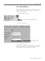
Secure a Project
Publication 1756-PM001G-EN-P - March 2004
When to Use This Procedure . . . . . . . . . . . . . . . . . . . . . . . 18-1
Use Routine Source Protection. . . . . . . . . . . . . . . . . . . . . . 18-1
Choose the Level of Protection for Each Routine . . . . . . 18-4
Choose the Number of Source Keys . . . . . . . . . . . . . . . 18-4
Define the Source Key or Keys. . . . . . . . . . . . . . . . . . . 18-5
Choose a File Location in Which to Store the Source Keys. .
18-5
Activate the RSLogix 5000 Source Protection Feature . . . 18-6
Create a File for the Source Keys . . . . . . . . . . . . . . . . . 18-6
Protect a Routine with a Source Key . . . . . . . . . . . . . . . 18-7
Remove Access to a Protected Routine . . . . . . . . . . . . . 18-8
Disable Routine Source Protection . . . . . . . . . . . . . . . . 18-9
Gain Access to a Protected Routine. . . . . . . . . . . . . . . 18-11
Table of Contents
Use RSI Security Server to Protect a Project . . . . . . . . . . .
Install RSI Security Server Software . . . . . . . . . . . . . . .
Set Up DCOM . . . . . . . . . . . . . . . . . . . . . . . . . . . . . .
Enable Security Server for RSLogix 5000 Software . . . .
Import the RSLogix5000Security.bak File . . . . . . . . . . .
Define the Global Actions for Your Users . . . . . . . . . .
Define the Project Actions for Your Users . . . . . . . . . .
Add Users . . . . . . . . . . . . . . . . . . . . . . . . . . . . . . . . .
Add User Groups. . . . . . . . . . . . . . . . . . . . . . . . . . . .
Assign Global Access to RSLogix 5000 Software. . . . . .
Assign Project Actions for New RSLogix 5000 Projects .
Secure an RSLogix 5000 Project . . . . . . . . . . . . . . . . .
Assign Access to an RSLogix 5000 Project . . . . . . . . . .
Refresh RSLogix 5000 Software, If Needed . . . . . . . . .
xi
18-13
18-13
18-14
18-14
18-15
18-16
18-17
18-20
18-20
18-21
18-22
18-23
18-24
18-25
Chapter 19
Determine Controller Memory
Information
When to Use This Chapter. . . . . . . . . . . . . . . . . . . .
Determine What Memory Information You Want . . .
Estimate Memory Information Offline. . . . . . . . . . . .
View Run Time Memory Information . . . . . . . . . . . .
Write Logic to Get Memory Information . . . . . . . . . .
Get Memory Information from the Controller . . .
Choose the Memory Information That You Want.
Convert INTs to a DINT . . . . . . . . . . . . . . . . . . .
.
.
.
.
.
.
.
.
.
.
.
.
.
.
.
.
.
.
.
.
.
.
.
.
.
.
.
.
.
.
.
.
.
.
.
.
.
.
.
.
19-1
19-1
19-2
19-3
19-4
19-4
19-5
19-6
.
.
.
.
.
.
.
.
.
.
.
.
.
.
.
.
.
.
.
.
.
.
.
.
.
.
.
.
.
.
.
.
.
.
.
.
.
.
.
.
.
.
.
.
.
.
.
.
.
.
.
.
.
.
.
A-1
A-1
A-1
A-2
A-2
A-2
A-2
A-3
A-3
A-4
A-4
Set Up the I/O Configuration . . . . . . . . . . . . . . . . .
Define Your Source and Destination Elements . . . .
Create the MESSAGE_CONFIGURATION Data Type
Create the Configuration Array . . . . . . . . . . . . . . . .
Get the Size of the Local Array . . . . . . . . . . . . . . . .
Load the Message Properties for a Controller. . . . . .
.
.
.
.
.
.
.
.
.
.
.
.
.
.
.
.
.
.
B-3
B-4
B-5
B-6
B-8
B-9
Appendix A
Manage Multiple Messages
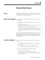
Purpose . . . . . . . . . . . . . . . . . . . . . .
When to Use this Appendix. . . . . . . .
How to Use this Appendix . . . . . . . .
Message Manager Logic. . . . . . . . . . .
Initialize the Logic . . . . . . . . . . . .
Restart the Sequence, If Required .
Send the First Group of MSGs . . .
Enable the Next Group of MSGs. .
Send the Next Group of MSGs . . .
Enable the Next Group of MSGs. .
Send the Next Group of MSGs . . .
.
.
.
.
.
.
.
.
.
.
.
.
.
.
.
.
.
.
.
.
.
.
.
.
.
.
.
.
.
.
.
.
.
.
.
.
.
.
.
.
.
.
.
.
.
.
.
.
.
.
.
.
.
.
.
.
.
.
.
.
.
.
.
.
.
.
.
.
.
.
.
.
.
.
.
.
.
.
.
.
.
.
.
.
.
.
.
.
.
.
.
.
.
.
.
.
.
.
.
.
.
.
.
.
.
.
.
.
.
.
.
.
.
.
.
.
.
.
.
.
.
Appendix B
Send a Message to Multiple
Controllers
Publication 1756-PM001G-EN-P - March 2004
Table of Contents
xii
Configure the Message . . . . . . . . . . . . . . . . . . . . . . . . B-10
Step to the Next Controller . . . . . . . . . . . . . . . . . . . . . B-11
Restart the Sequence . . . . . . . . . . . . . . . . . . . . . . . . . B-11
Appendix C
IEC61131-3 Compliance
Publication 1756-PM001G-EN-P - March 2004
Using This Appendix. . . . . . . .
Introduction . . . . . . . . . . . . . .
Operating System . . . . . . . . . .
Data Definitions . . . . . . . . . . .
Programming Languages . . . . .
Instruction Set. . . . . . . . . . . . .
IEC61131-3 Program Portability
IEC Compliance Tables . . . . . .
.
.
.
.
.
.
.
.
.
.
.
.
.
.
.
.
.
.
.
.
.
.
.
.
.
.
.
.
.
.
.
.
.
.
.
.
.
.
.
.
.
.
.
.
.
.
.
.
.
.
.
.
.
.
.
.
.
.
.
.
.
.
.
.
.
.
.
.
.
.
.
.
.
.
.
.
.
.
.
.
.
.
.
.
.
.
.
.
.
.
.
.
.
.
.
.
.
.
.
.
.
.
.
.
.
.
.
.
.
.
.
.
.
.
.
.
.
.
.
.
.
.
.
.
.
.
.
.
.
.
.
.
.
.
.
.
.
.
.
.
.
.
.
.
.
.
.
.
.
.
.
.
.
.
.
.
.
.
.
.
.
.
.
.
.
.
.
.
C-1
C-1
C-2
C-2
C-3
C-4
C-4
C-5
Chapter
1
Getting Started
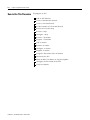
Using This Chapter
Create a Project
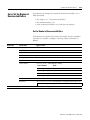
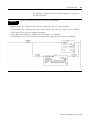
This chapter provides preliminary information to help you get started
with a project for Logix5000™ controller.
For this information or procedure
See this page:
Create a Project
1-1
Explore a Project
1-4
Create Routines
1-7
Verify a Project
1-12
Save a Project
1-12
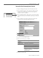
Configure a Communication Driver
1-13
Download a Project to the Controller
1-14
Select a Mode for the Controller
1-16
Manually Clear a Major Fault
1-17
Configure the Execution of a Task
1-18
Create Multiple Programs
1-20
Access Status Information
1-22
Adjust the System Overhead Time Slice
1-26
View Scan Time
1-29
Adjust the Watchdog Time
1-31
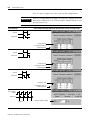
To configure and program a Logix5000 controller, you use
RSLogix™ 5000 software to create and manage a project for the
controller.
Term:
Definition:
project
The file on your workstation (or server) that stores the logic, configuration, data, and
documentation for a controller.
• The project file has an .ACD extension.
• When you create a project file, the file name is the name of the controller.
• The controller name is independent of the project file name. If you save a current
project file as another name, the controller name is unchanged.
• If the name of the controller is different than the name of the project file, the title
bar of the RSLogix 5000 software displays both names.
1
Publication 1756-PM001G-EN-P - March 2004
1-2
Getting Started
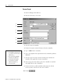
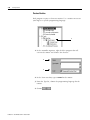
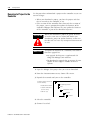
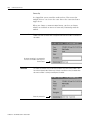
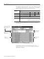
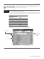
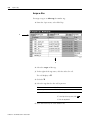
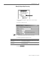
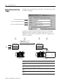
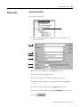
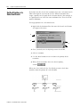
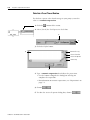
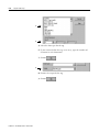
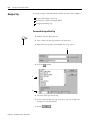
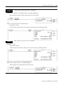
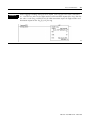
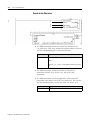
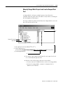
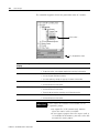
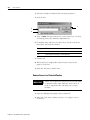
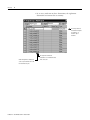
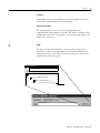
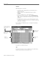
Create a Project
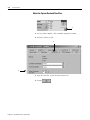
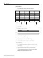
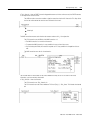
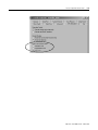
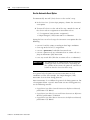
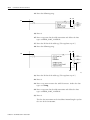
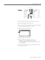
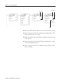
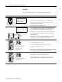
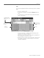
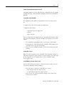
1. Start the RSLogix 5000 software.
2. From the File menu, select New.
3.
4.
5.
6.
7.
8.
9.
42194
3. Select the type of controller.
4. Choose the major revision of firmware for this controller.
Names:
• only alphabetic characters (A-Z or
a-z), numeric characters (0-9), and
underscores (_)
• must start with an alphabetic
character or an underscore
• no more than 40 characters
• no consecutive or trailing
underscore characters (_)
• not case sensitive
5. Type a name for the controller.
6. Type a description of the operations that the controller performs
(optional).
7. Select the type of chassis (number of slots) that contains the
controller (not applicable to some controllers).
8. Select or type the slot number where the controller is installed
(not applicable to some controllers).
9. To store the file in a different folder (other than the default
Create In path), click Browse and select a folder.
10. Choose
Publication 1756-PM001G-EN-P - March 2004
Getting Started
1-3
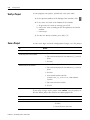
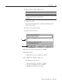
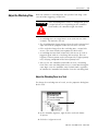
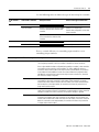
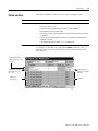
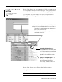
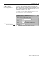
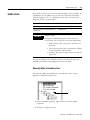
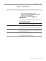
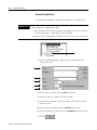
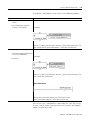
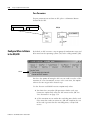
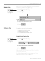
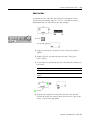
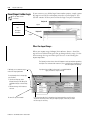
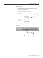
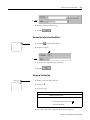
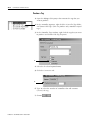
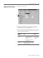
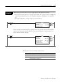
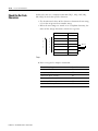
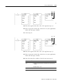
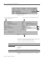
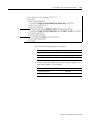
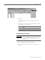
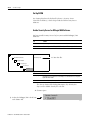
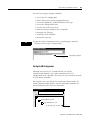
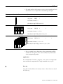
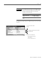
Configure a Project
To change the configuration of the controller, such as name, chassis
size, or slot number, use the Controller Properties dialog box.
1.
42627
1. On the Online toolbar, click the controller properties button.
2. Make the required changes.
3. Choose
Publication 1756-PM001G-EN-P - March 2004
1-4
Getting Started
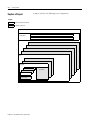
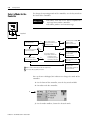
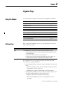
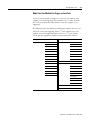
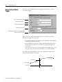
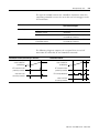
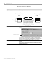
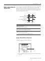
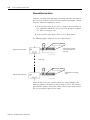
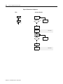
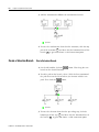
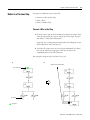
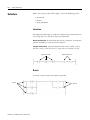
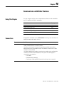
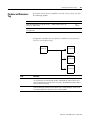
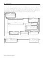
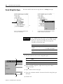
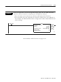
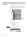
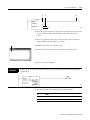
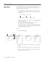
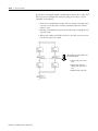
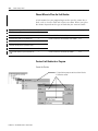
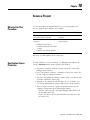
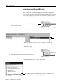
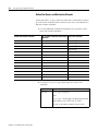
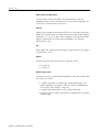
Explore a Project
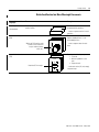
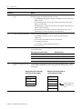
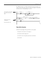
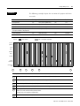
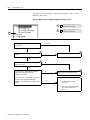
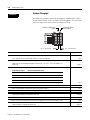
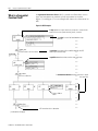
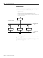
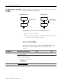
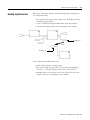
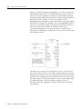
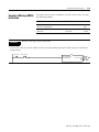
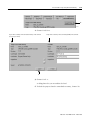
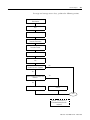
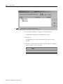
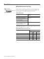
A project includes the following basic components:
Legend
default (required) component
optional component
project
controller tags
(global data)
I/O data
system-shared data
power-up handler
controller fault handler
task
task
task
program
program
program
other routines
main routine
fault routine
Publication 1756-PM001G-EN-P - March 2004
program tags
(local data)
Getting Started
1-5
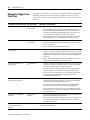
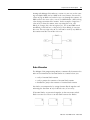
The components of a project work together as follows:
Project component:
Definition:
Task
A task provides scheduling and priority information for a set of one or more programs.
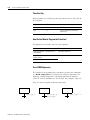
When you create a new project, RSLogix 5000 software automatically creates an initial task that is
configured to run all the time (continuous task). When the task completes a full scan, it restarts
immediately.
Program
Each task requires at least one program.
• A task can have as many as 32 separate programs, each with its own program tags, main routine,
other routines, and an optional fault routine.
• Once a task is triggered (activated), all the programs assigned (scheduled) to the task execute in the
order in which they are displayed in the controller organizer.
• You schedule a program in only one task and cannot share a program among multiple tasks.
Routine
Routines provide the executable code for the project in a controller (similar to a program file in a PLC or
SLC controller). Each routine uses a specific programming language, such as ladder logic.
Main Routine
When a program executes, its main routine executes first. Use the main routine to call (execute) other
routines (subroutines). To call another routine within the program, use a Jump to Subroutine (JSR)
instruction.
Subroutine
Any routine other than the main routine or fault routine. To execute a subroutine, use a Jump to Subroutine
(JSR) instruction in another routine, such as the main routine.
Publication 1756-PM001G-EN-P - March 2004
1-6
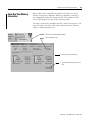
Getting Started
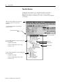
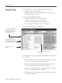
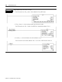
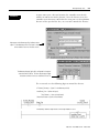
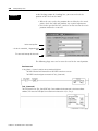
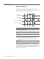
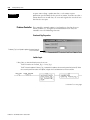
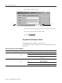
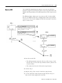
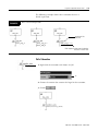
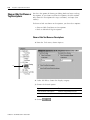
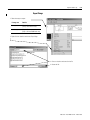
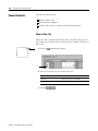
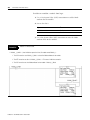
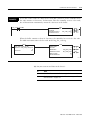
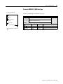
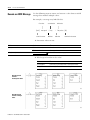
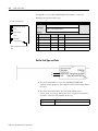
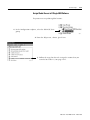
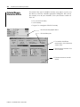
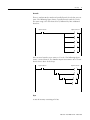
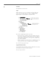
Controller Organizer
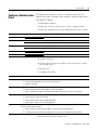
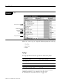
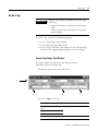
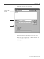
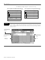
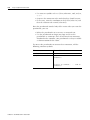
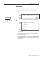
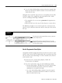
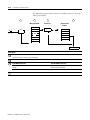
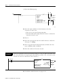
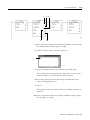
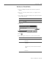
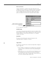
In RSLogix 5000 software, the controller organizer provides a
graphical overview of a project. When you create a project,
RSLogix5000 software automatically creates a default task, program,
and routine.
When you create a project, the name of the
project is the same as the name of the
controller.
If you rename the project or controller, both
names are shown.
controller organizer
name of the controller
To close a folder and hide its contents (collapse), do
one of the following:
• Double-click the folder.
• Select the folder and press the [←] key.
• Click the – sign.
To open a folder and display its contents (expand), do
one of the following:
• Double-click the folder.
• Select the folder and press the [→] key.
• Click the + sign.
Publication 1756-PM001G-EN-P - March 2004
default task
default program
default routine
Getting Started
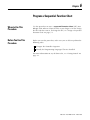
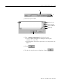
Create Routines
1-7
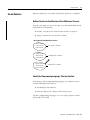
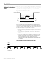
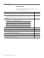
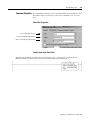
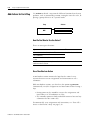
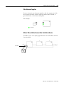
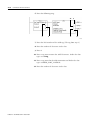
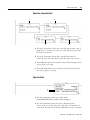
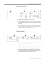
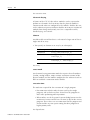
Routines provide the executable code for the project in a controller.
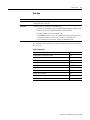
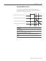
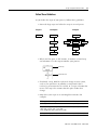
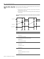
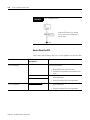
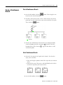
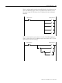
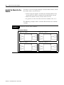
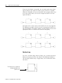
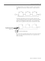
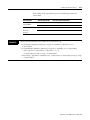
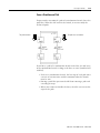
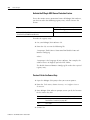
Define a Routine for Each Section of Your Machine or Process
To make your project easier to develop, test, and troubleshoot, divide
it into routines (subroutines):
1. Identify each physical section of your machine or process.
2. Assign a routine for each of those sections.
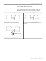
Description of Your Machine or Process
Xxxxx xxxxx xxx
Xxxxx xxxxx xxx
Xxxxx xxxxx xxx
first section = routine 1
Xxxxx xxxxx xxx
Xxxxx xxxxx xxx
Xxxxx xxxxx xxx
second section = routine 2
Xxxxx xxxxx xxx
Xxxxx xxxxx xxx
Xxxxx xxxxx xxx
third section = routine 3
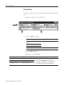
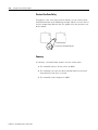
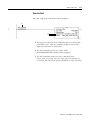
Identify the Programming Languages That Are Installed
To determine which programming languages are installed on your
version of RSLogix 5000 software:
1. Start RSLogix 5000 software.
2. From the Help menu, choose About RSLogix 5000.
To add a programming language, see ControlLogix Selection Guide,
publication 1756-SG001.
Publication 1756-PM001G-EN-P - March 2004
1-8
Getting Started
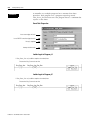
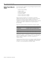
Choose a Programming Language for Each Section
For each section of your machine or process, choose an appropriate
programming language.
• Logix5000 controllers let you use the following languages:
– ladder logic
– function block diagram
– sequential function chart
– structured text
• Use any combination of the languages in the same project.
In general, if a section of your code represents:
Then use this language:
continuous or parallel execution of multiple operations (not sequenced)
ladder logic
boolean or bit-based operations
complex logical operations
message and communication processing
machine interlocking
operations that service or maintenance personnel may have to interpret in order
to troubleshoot the machine or process.
continuous process and drive control
function block diagram
loop control
calculations in circuit flow
high-level management of multiple operations
sequential function chart (SFC)
repetitive sequences of operations
batch process
motion control using structured text
state machine operations
complex mathematical operations
specialized array or table loop processing
ASCII string handling or protocol processing
Publication 1756-PM001G-EN-P - March 2004
structured text
Getting Started
1-9
Divide Each Routine Into More Meaningful Increments
If a routine uses this
language:
Then:
Example:
ladder logic
Break up large routines into several
smaller routines
To continuously execute several
complex boolean operations…
structured text
routine
function block diagram
(FBD)
routine
Within the FBD routine, make
a sheet for each functional
loop for a device (motor,
valve, etc.).
To control 4 valves, where each valve
requires feedback that it is in its
commanded position…
…make a separate sheet for each
valve.
sheet
sequential function chart
(SFC)
routine
step
Break the SFC into steps.
…create a separate routine for each
operation.
step
step
To perform the following sequence:
1. Fill a tank.
2. Mix the ingredients in the
tank.
3. Empty the tank…
…make each section (fill, mix, empty)
a separate step.
Publication 1756-PM001G-EN-P - March 2004
1-10
Getting Started
Create a Routine
Each program requires at least one routine. Use a routine to execute
your logic in a specific programming language.
1.
1. In the controller organizer, right-click the program that will
execute the routine and choose New Routine.
2.
3.
2. In the Name text box, type a name for the routine.
3. From the Type list, choose the programming language for the
routine
4. Choose
Publication 1756-PM001G-EN-P - March 2004
Getting Started
1-11
Open a Routine
To open a folder and show its contents, either:
• Double-click the folder.
• Click the + sign.
To open a routine, double-click the routine. If a routine is grayed-out, you
cannot open the routine.
source protection – The developer of the routine may have assigned a
source key to the routine. The source key limits access to the routine.
If the controller organizer lists source protection for a routine, then a source
key is assigned to the routine.
For this routine…
This is the protection status.
If:
Then:
Source Not Available To open the routine, your computer requires the
source key for the routine.
Source Not Available
(Viewable)
IMPORTANT
• You can only open and view the routine.
• You cannot make any changes or copy
any of contents of the routine.
Source Available
You have full access to the routine.
Source Available
(Viewable)
You have full access to the routine.
If the source of a routine is unavailable, do not export the project.
• An export file (.L5K) contains only routines where the source code is available.
• If you export a project where the source code is not available for all routines, you
will not be able to restore the entire project.
TIP
If a routine fails to open, your computer may not have the required programming
language installed.
• To determine which programming languages are installed on your computer, choose
Help ⇒ About RSLogix 5000.
• To add a programming language, see ControlLogix Selection Guide, publication
1756-SG001
Publication 1756-PM001G-EN-P - March 2004
1-12
Getting Started
Verify a Project
As you program your project, periodically verify your work:
1. In the top-most toolbar of the RSLogix 5000 window, click
2. If any errors are listed at the bottom of the window:
a. To go to the first error or warning, press [F4].
b. Correct the error according to the description in the Results
window.
c. Go to step 1.
3. To close the Results window, press [Alt] + [1].
Save a Project
As you create logic and make configuration changes, save the project.
To:
Do this:
save your changes
From the File menu, select Save.
make a copy of the open project but keep
the existing name of the controller
1. From the File menu, select Save As.
2. Type a name for the project file. Use underscores [ _ ] in place of
spaces.
3. Click Save.
make a copy of the project and assign a
different name to the controller
1. From the File menu, select Save As.
2. Type a name for the project file. Use underscores [ _ ] in place of
spaces.
3. Click Save.
4. In the controller organizer, right-click
Controller name_of_controller folder and select
Properties.
5. Type a new name for the controller.
6. Click OK.
If you make changes to the project while online, save the project so
that the offline project file matches the online project file:
If you want to:
Do this:
save online changes and data values
From the File menu, select Save.
save online changes but not online data values
1. From the Communications menu, select
Go Offline.
2. From the File menu, select Save.
Publication 1756-PM001G-EN-P - March 2004
Getting Started
Configure a Communication
Driver
1-13
The RSLogix 5000 software requires a communication driver to
communicate with a controller. You configure communication drivers
using RSLinx® software:
1. Start RSLinx software.
2. From the Communications menu, select Configure Drivers.
3. From the Available Driver Types drop-down list, select a driver:
For this network:
And this type of computer:
serial
DH+™
ControlNet™
Select this driver:
RS-232 DF1 Devices
desktop computer
1784-KT/KTX(D)/PKTX(D)
laptop computer
1784-PCMK
desktop computer
1784-KTC(X)
laptop computer
1784-PCC
EtherNet/IP
Ethernet devices
DeviceNet™
DeviceNet Drivers (1784-PCD/PCIDS, 1770-KFD, SDNPT drivers)
4. Choose Add New.
5. If you want to assign a descriptive name to the driver, change
the default name.
6. Choose OK.
7. Configure the driver:
For this driver:
serial
Do this:
A. From the Comm Port drop-down list, select the serial port that the driver will use.
B. From the Device drop-down list, select Logix 5550-Serial Port.
C. Click Auto-Configure.
ControlNet
A. In the Station Name box, type a name that will identify the computer in the RSWho window.
B. Select the interrupt value, memory address, and I/O base address.
C. In the Net Address box, type the ControlNet node number that you want to assign to the computer.
DH+
A. From the Value drop-down list, select the type of interface card that the driver will use.
B. In the Property list, select the next item.
C. In the Value box, type or select the appropriate value.
D. Repeat steps B. and C. for the remaining properties.
Ethernet
For each Ethernet device on this network with which you want to communicate (e.g., each 1756-ENB module or
PLC-5E controller), add a map entry:
A. In the Host Name column, type the IP address or host name of the Ethernet device.
B. To communicate with another Ethernet device on this network, choose Add New and go to Step A.
8. Choose OK. and then choose Close.
Publication 1756-PM001G-EN-P - March 2004
1-14
Getting Started
Download a Project to the
Controller
Use this procedure to download a project to the controller so you can
execute its logic.
• When you download a project, you lose the project and data
that is currently in the controller, if any.
• If the revision of the controller does not match the revision of
the project, you are prompted to update the firmware of the
controller. RSLogix 5000 software lets you update the firmware
of the controller as part of the download sequence.
ATTENTION
!
IMPORTANT
When you download a project or update firmware,
all active servo axes are turned off. Before you
download a project or update firmware, make sure
that this will not cause any unexpected movement of
an axis.
To update the firmware of a controller, first install a
firmware upgrade kit.
• An upgrade kit ships on a supplemental CD
along with RSLogix 5000 software.
• To download an upgrade kit, go to www.ab.com.
Choose Product Support. Choose Firmware
Updates.
1. Open the RSLogix 5000 project that you want to download.
2. From the Communications menu, choose Who Active.
3. Expand the network until you see the controller.
To expand a network one level, do
one of the following:
• Double-click the network.
• Select the network and
press the → key.
• Click the + sign.
−
Workstation
+
Linx Gateways, Ethernet
−
driver
−
communication module
−
backplane
+
4. Select the controller.
5. Choose Download.
Publication 1756-PM001G-EN-P - March 2004
controller
Getting Started
1-15
6. Which response did the software give:
If the software indicates:
Then:
Download to the controller
Go to step 7.
Failed to download to the controller. The revision of the
offline project and controller’s firmware are not
compatible.
Go to step 9.
7. Choose Download.
The project downloads to the controller and RSLogix 5000
software goes online.
8. Skip the rest of this procedure.
9. Choose Update Firmware.
10.
11.
43056
10. Select the required revision for the controller.
11. Choose Update.
A dialog box asks you to confirm the update.
12. To update the controller, choose Yes.
The following events occur:
• The firmware of the controller is updated.
• The project downloads to the controller.
• RSLogix 5000 software goes online.
Publication 1756-PM001G-EN-P - March 2004
1-16
Getting Started
Select a Mode for the
Controller
To change the operating mode of the controller, use the keyswitch on
the front of the controller:
IMPORTANT
• All modes send and receive data in response to a
message from another controller.
• All modes produce and consume tags.
keyswitch
Do you need to schedule a
ControlNet network?
Yes
Do you want to prevent
RSLogix 5000 software from
changing the mode?
No
No
Yes
Do you want to execute the
logic in the controller?
B
No
Yes
Do you want the logic to
control the output devices?
Yes
Do you want to prevent
RSLogix 5000 software from:
• changing the mode
• downloading a project
• performing online edits
No
Yes
Turn the keyswitch to PROG
and then to REM
(Remote Program mode).
Turn the keyswitch to PROG
(Program mode).
A
A
Turn the keyswitch to RUN
and then to REM
(Remote Run mode).
Turn the keyswitch to RUN
(Run mode).
No
A
A Outputs revert to their configured state for Program mode.
B This includes Message (MSG) instructions.
1. Turn the keyswitch to REM.
2. Go online with
RSLogix 5000 software and
choose Test mode.
You can also use RSLogix 5000 software to change the mode of the
controller:
1. On the front of the controller, turn the keyswitch to REM.
2. Go online with the controller.
3.
3. On the online toolbar, choose the desired mode.
Publication 1756-PM001G-EN-P - March 2004
Getting Started
Manually Clear a Major
Fault
1-17
If the controller enters the faulted mode, a major fault occurred and
the controller stopped executing the logic.
The controller is faulted. A major fault
occurred and the controller is no longer
executing its logic.
43057
1.
To correct a major fault:
1. Click the
button.
2. Use the information in the Recent faults list to correct the cause
of the fault. Refer to "Major Fault Codes" on page 15-15.
3. Click the Clear Majors button.
TIP
You can also clear a major fault by using the
keyswitch on the controller. Turn the keyswitch to
Prog, then to Run, and then back to Prog.
Publication 1756-PM001G-EN-P - March 2004
1-18
Getting Started
Configure the Execution of
a Task
When you create a new project, RSLogix 5000 software automatically
creates an initial task that is configured to run all the time (continuous
task). When the task completes a full scan, it restarts immediately.
Figure 1.1 Execution of the Continuous Task
start of the continuous task
end of the continuous task
program
subroutine
main routine
task automatically restarts
If you are familiar with a DCS application or plan to program your
system using a function block diagram, you can configure the task to
execute at a specific period (periodic task). This lets you update your
function block diagram at a period that you specify.
• Whenever the time period for the task expires, the task executes
one time.
• You configure the period from 1 ms to 2000 s. The default is
10 ms.
• If you use a periodic task in addition to a continuous task, the
periodic task interrupts the execution of the continuous task.
When the periodic task is done, control returns to the
continuous task. For more information on using multiple tasks,
see chapter 4.
Figure 1.2 Example of a Periodic Task That Executes Every 10 ms.
Legend:
Task executes.
periodic
task
5
10
elapsed time (ms)
Publication 1756-PM001G-EN-P - March 2004
15
20
25
30
35
40
45
50
Getting Started
1-19
Configure a Task
To configure the execution of a task, use the properties dialog box for
the task.
1.
1. In the controller organizer, right-click the task that you want to
configure and choose Properties.
2. Click the Configuration tab.
3.
4.
3. From the Type list, choose type of execution for the task. Only
one continuous task is permitted.
4. If you chose Periodic in step 3, then type the rate at which you
want the task to execute.
5. Choose
Publication 1756-PM001G-EN-P - March 2004
1-20
Getting Started
Create Multiple Programs
A Logix5000 controller lets you divide your application into multiple
programs, each with its own data. There is no need to manage
conflicting tag names between programs. This makes it easier to
re-use both code and tag names in multiple programs.
controller tags (global data)
All programs have access to
data that is at the controller
scope.
Tag_1
Tag_2
Tag_3
Program_A
other routines
main routine
Program_B
program tags
(local data)
Tag_4
Tag_5
Tag_6
program tags
(local data)
other routines
data
Tag_4
Tag_5
Tag_6
main routine
Data at the program scope is isolated from other programs:
• Routines cannot access data that is at the program scope of another program.
• You can re-use the tag name of a program-scoped tag in multiple programs.
For example, both Program_A and Program_B can have a program tag named
Tag_4.
Create a Program
Each task requires at least one program. You can create multiple
programs for a task.
1.
1. In the controller organizer, right-click the task that will execute
the program and choose New Program.
Publication 1756-PM001G-EN-P - March 2004
Getting Started
1-21
2.
2. In the Name text box, type a name for the program.
3. Choose
Configure a Program
Each program requires a main routine. The main routine executes
whenever the program executes.
1.
1. In the controller organizer, right-click the program that you want
to configure and choose Properties.
2. Click the Configuration tab.
3.
3. From the Main list, choose the name of the routine that you
want to execute as the main routine.
4. Choose
Publication 1756-PM001G-EN-P - March 2004
1-22
Getting Started
Access Status Information
Logix5000 controllers do not have a status file, as in the PLC-5
controller. To access status information, you use a keyword or access
a specific object.
If you want to:
See:
use specific key words in your logic to monitor specific events
“Monitor Status Flags” on page 1-22
get or set system values
“Get and Set System Data” on page 1-23
Monitor Status Flags
The controller supports status keywords you can use in your logic to
monitor specific events:
• The status keywords are not case sensitive.
• Because the status flags can change so quickly, RSLogix 5000
software does not display the status of the flags. (I.e., Even
when a status flag is set, an instruction that references that flag is
not highlighted.)
• You cannot define a tag alias to a keyword.
You can use these key words:
To determine if:
Use:
the value you are storing cannot fit into the destination because it is
either:
• greater than the maximum value for the destination
S: V
• less than the minimum value for the destination
Important: Each time S:V goes from cleared to set, it generates a
minor fault (type 4, code 4)
the instruction’s destination value is 0
S:Z
the instruction’s destination value is negative
S:N
an arithmetic operation causes a carry or borrow that tries to use bits
that are outside of the data type
S:C
For example:
• adding 3 + 9 causes a carry of 1
• subtracting 25 - 18 causes a borrow of 10
this is the first, normal scan of the routines in the current program
S:FS
at least one minor fault has been generated:
• The controller sets this bit when a minor fault occurs due to
program execution.
S:MINOR
• The controller does not set this bit for minor faults that are not
related to program execution, such as battery low.
Publication 1756-PM001G-EN-P - March 2004
Getting Started
1-23
Get and Set System Data
The controller stores system data in objects. There is no status file, as
in the PLC-5 controller. Use the GSV/SSV instructions get and set
controller system data that is stored in objects:
• The GSV instruction retrieves the specified information and
places it in the destination.
• The SSV instruction sets the specified attribute with data from
the source.
ATTENTION
!
Use the SSV instruction carefully. Making changes to
objects can cause unexpected controller operation or
injury to personnel.
To get or set a system value:
1. Open the RSLogix 5000 project.
2. From the Help menu, select Contents.
3. Click the Index tab.
4. Type gsv/ssv objects and click Display.
Publication 1756-PM001G-EN-P - March 2004
1-24
Getting Started
5. Click the required object.
To get or set:
Click:
axis of a servo module
AXIS
system overhead timeslice
CONTROLLER
physical hardware of a controller
CONTROLLERDEVICE
coordinated system time for the devices in one
chassis
CST
DF1 communication driver for the serial port
DF1
fault history for a controller
FAULTLOG
attributes of a message instruction
MESSAGE
status, faults, and mode of a module
MODULE
group of axes
MOTIONGROUP
fault information or scan time for a program
PROGRAM
instance number of a routine
ROUTINE
configuration of the serial port
SERIALPORT
properties or elapsed time of a task
TASK
wall clock time of a controller
WALLCLOCKTIME
6. In the list of attributes for the object, identify the attribute that
you want to access.
7. Create a tag for the value of the attribute:
If the data type of the attribute
is:
Then:
one element (e.g., DINT)
Create a tag for the attribute.
more than one element (e.g.,
DINT[7] )
A. Create a user-defined data type that
matches the organization of data
that is used by the attribute.
B. Create a tag for the attribute and
use the data type from Step A..
8. In your ladder logic routine, enter the appropriate instruction:
Publication 1756-PM001G-EN-P - March 2004
To:
Enter this instruction:
get the value of an attribute
GSV
set the value of an attribute
SSV
Getting Started
1-25
9. Assign the required operands to the instruction:
For this operand:
Select:
Class name
name of the object
Instance name
name of the specific object (e.g., name of
the required I/O module, task, message)
• Not all objects require this entry.
• To specify the current task, program,
or routine, select THIS.
Attribute Name
name of the attribute
Dest (GSV)
tag that will store the retrieved value
• If the tag is a user-defined data type
or an array, select the first member
or element.
Source (SSV)
tag that stores the value to be set
• If the tag is a user-defined data type
or an array, select the first member
or element.
The following examples gets the current date and time.
EXAMPLE
Get a system value
At the first scan, gets the DateTime attribute of the WALLCLOCKTIME object and stores it in the
wall_clock tag, which is based on a user-defined data type.
42370
For more information, see the Logix5000 Controllers General
Instruction Set Reference Manual, publication 1756-RM003.
Publication 1756-PM001G-EN-P - March 2004
1-26
Getting Started
Adjust the System Overhead
Time Slice
A Logix5000 controller communicates with a other devices (I/O
modules, controllers, HMI terminals, etc.) at either a specified rate
(scheduled) or when there is processing time available to service the
communication (unscheduled).
This type of communication:
Is:
update I/O data (not including block-transfers)
Scheduled Communication
produce or consume tags
communicate with programming devices (e.g., RSLogix 5000 software)
Unscheduled Communication
communicate with HMI devices
execute Message (MSG) instructions, including block-transfers
respond to messages from other controllers
synchronize the secondary controller of a redundant system
re-establish and monitor I/O connections (such as Removal and Insertion Under
Power conditions); this does not include normal I/O updates that occur during the
execution of logic.
bridge communications from the serial port of the controller to other ControlLogix
devices via the ControlLogix backplane
Unscheduled communication is any communication that you do not
configure through the I/O configuration folder of the project.
• The system overhead time slice specifies the percentage of
time (excluding the time for periodic or event tasks) that the
controller devotes to unscheduled communication.
• The controller performs unscheduled communication for up to
1 ms at a time and then resumes the continuous task.
The following table shows the ratio between the continuos task and
unscheduled communication at various system overhead time slices:
Publication 1756-PM001G-EN-P - March 2004
At this time slice:
The continuous tasks runs for:
And unscheduled communication
occurs for up to:
10%
9 ms
1 ms
20%
4 ms
1 ms
33%
2 ms
1 ms
50%
1 ms
1 ms
Getting Started
1-27
At a system overhead time slice to 20 %, unscheduled communication
occurs every 4 ms of continuous task time for 1 ms.
Legend:
Task executes.
Task is interrupted (suspended).
1 ms
1 ms
1 ms
1 ms
1 ms
unscheduled communication
4 ms
4 ms
4 ms
4 ms
4 ms
continuous task
If you increase the system overhead time slice to 33 %, unscheduled
communication occurs every 2 ms of continuous task time for 1 ms.
1 ms
1 ms
1 ms
1 ms
1 ms
1 ms
1 ms
1 ms
unscheduled communication
2 ms
2 ms
2 ms
2 ms
2 ms
2 ms
2 ms
2 ms
2 ms
continuous task
If the controller contains only a periodic task or tasks, the system
overhead time slice value has no effect. Unscheduled communication
occurs whenever a periodic task is not running.
For example, if your task takes 50 ms to execute and you configure its
update rate to 80 ms, the controller has 30 ms out of every 80 ms for
unscheduled communication.
50 ms
50 ms
50 ms
periodic task
30 ms
30 ms
30 ms
unscheduled communication
Publication 1756-PM001G-EN-P - March 2004
1-28
Getting Started
Adjust the System Overhead Time Slice
1.
1. On the Online toolbar, click controller properties button.
2. Click the Advanced tab.
2.
3.
3. Type or select the system overhead time slice.
4. Choose
Publication 1756-PM001G-EN-P - March 2004
Getting Started
View Scan Time
1-29
A Logix5000 controller provides two types of scan times. Each serves a
different purpose:
If you want to determine the:
Then:
Notes:
time that has elapsed from the start of a task
to the end of the task, in milliseconds
View Task Scan Time
The scan time of a task includes the time that the
task is interrupted to service communications or
other tasks.
time to execute the logic of a program (its
main routine and any subroutines that the
main routine calls), in microseconds
View Program Scan Time
The scan time of a program includes only the
execution time of the logic. It does not include any
interrupts.
View Task Scan Time
To see the scan time of a task, display the properties for the task.
1.
1. In the controller organizer, right-click the task whose scan time
you want to view and choose Properties.
2. Click the Monitor tab.
maximum scan time of the program
scan timescan
of the
time
lastofexecution
the last execution
of this program
of this
3. To close the dialog box, choose
Publication 1756-PM001G-EN-P - March 2004
1-30
Getting Started
View Program Scan Time
To see the scan time of a program, display the properties for the
program.
1.
1. In the controller organizer, right-click the program whose scan
time you want to view and choose Properties.
2. Click the Configuration tab.
maximum scan time of the program
scan timescan
of the
time
lastofexecution
the last execution
of this program
of this
3. To close the dialog box, choose
Publication 1756-PM001G-EN-P - March 2004
Getting Started
Adjust the Watchdog Time
1-31
Each task contains a watchdog timer that specifies how long a task
can run before triggering a major fault.
ATTENTION
!
If the watchdog timer reaches a configurable preset,
a major fault occurs. Depending on the controller
fault handler, the controller might shut down.
• A watchdog time can range from 1 ms to 2,000,000 ms (2000
seconds). The default is 500 ms.
• The watchdog timer begins to time when the task is initiated and
stops when all the programs within the task have executed.
• If the task takes longer than the watchdog time, a major fault
occurs. (The time includes interruptions by other tasks.)
• A watchdog time-out fault (major fault) also occurs if a task is
triggered again while it is executing (task overlap). This can
happen if a lower-priority task is interrupted by a higher-priority
task, delaying completion of the lower-priority task.
• You can use the controller fault handler to clear a watchdog
fault. If the same watchdog fault occurs a second time during the
same logic scan, the controller enters faulted mode, regardless
of whether the controller fault handler clears the watchdog fault.
Adjust the Watchdog Timer for a Task
To change the watchdog time of a task, use the properties dialog box
for the task.
1.
1. In the controller organizer, right-click the task and choose
Properties.
2. Click the Configuration tab.
Publication 1756-PM001G-EN-P - March 2004
1-32
Getting Started
3.
3. Type the watchdog time for the task, in milliseconds.
4. Choose
Publication 1756-PM001G-EN-P - March 2004
Chapter
2
Communicate with I/O
Using This Chapter
This chapter provides basic information on how a Logix5000
controller communicates with I/O modules.
Configure an I/O Module
For this information or procedure
See this page:
Configure an I/O Module
2-1
Address I/O Data
2-7
Buffer I/O
2-8
To communicate with an I/O module in your system, you add the
module to the I/O Configuration folder of the controller.
Add I/O modules here.
When you add the module, you also define a specific configuration
for the module. While the configuration options vary from module to
module, there are some common options that you typically configure:
• Requested Packet Interval
• Communication Format
• Electronic Keying
1
Publication 1756-PM001G-EN-P - March 2004
2-2
Communicate with I/O
Requested Packet Interval
The Logix5000 controller uses connections to transmit I/O data.
Term:
Definition:
Connection
A communication link between two devices, such as between a controller and an I/O module, PanelView
terminal, or another controller.
Connections are allocations of resources that provide more reliable communications between devices than
unconnected messages. The number of connections that a single controller can have is limited.
You indirectly determine the number of connections the controller uses by configuring the controller to
communicate with other devices in the system. The following types of communication use connections:
• I/O modules
• produced and consumed tags
• certain types of Message (MSG) instructions (not all types use a connection)
requested packet
interval (RPI)
The RPI specifies the period at which data updates over a connection. For example, an input module sends data
to a controller at the RPI that you assign to the module.
• Typically, you configure an RPI in milliseconds (ms). The range is 0.2 ms (200 microseconds) to 750 ms.
• If a ControlNet network connects the devices, the RPI reserves a slot in the stream of data flowing across
the ControlNet network. The timing of this slot may not coincide with the exact value of the RPI, but the
control system guarantees that the data transfers at least as often as the RPI.
In Logix5000 controllers, I/O values update at a period that you
configure via the I/O configuration folder of the project. The values
update asynchronous to the execution of logic. At the specified
interval, the controller updates a value independently from the
execution of logic.
ATTENTION
!
Take care to ensure that data memory contains the
appropriate values throughout a task’s execution.
You can duplicate or buffer data at the beginning of
the scan to provide reference values for your logic.
• Programs within a task access input and output data directly
from controller-scoped memory.
• Logic within any task can modify controller-scoped data.
• Data and I/O values are asynchronous and can change during
the course of a task’s execution.
• An input value referenced at the beginning of a task’s execution
can be different when referenced later.
• To prevent an input value from changing during a scan, copy
the value to another tag and use the data from there (buffer the
values). To buffer your I/O values, see page 2-8.
Publication 1756-PM001G-EN-P - March 2004
Communicate with I/O
2-3
Communication Format
The communication format that you choose determines the data
structure for the tags that are associated with the module. Many I/O
modules support different formats. Each format uses a different
data structure. The communication format that you choose also
determines:
• Direct or Rack-Optimized Connection
• Ownership
Direct or Rack-Optimized Connection
The Logix5000 controller uses connections to transmit I/O data. These
connections can be direct connections or rack-optimized connections.
Term:
Definition:
direct connection
A direct connection is a real-time, data transfer link between the controller and an I/O
module. The controller maintains and monitors the connection with the I/O module. Any
break in the connection, such as a module fault or the removal of a module while under
power, sets fault bits in the data area associated with the module.
A direct connection is any connection
that does not use the Rack Optimization
Comm Format.
rack-optimized
connection
For digital I/O modules, you can select rack-optimized communication. A rack-optimized
connection consolidates connection usage between the controller and all the digital I/O
modules in the chassis (or DIN rail). Rather than having individual, direct connections for
each I/O module, there is one connection for the entire chassis (or DIN rail).
rack-optimized connection
Publication 1756-PM001G-EN-P - March 2004
2-4
Communicate with I/O
Ownership
In a Logix5000 system, modules multicast data. This means that
multiple devices can receive the same data at the same time from a
single device.
When you choose a communication format, you have to choose
whether to establish an owner or listen-only relationship with the
module.
owner controller
The controller that creates the primary configuration and communication connection to a
module. The owner controller writes configuration data and can establish a connection to
the module.
An owner connection is any connection
that does not include Listen-Only in its
Comm Format.
listen-only
connection
An I/O connection where another controller owns/provides the configuration data for the
I/O module. A controller using a listen-only connection only monitors the module. It does
not write configuration data and can only maintain a connection to the I/O module when
the owner controller is actively controlling the I/O module.
listen-only connection
Publication 1756-PM001G-EN-P - March 2004
Communicate with I/O
2-5
Use the following table to choose the type of ownership for a module:
If the module is
an:
And another controller:
input module
does not own the module
owns the module
output module
And you want to:
Then use this type of connection:
owner (i.e., not listen-only)
maintain communication with the module
if it loses communication with the other
controller
owner (i.e., not listen-only)
stop communication with the module if it
loses communication with the other
controller
listen-only
Use the same configuration as the other
owner controller.
does not own the module
owner (i.e., not listen-only)
owns the module
listen-only
There is a noted difference in controlling input modules versus
controlling output modules.
Controlling:
This ownership:
Description:
input modules
owner
An input module is configured by a controller that establishes a connection as an owner.
This configuring controller is the first controller to establish an owner connection.
Once an input module has been configured (and owned by a controller), other controllers
can establish owner connections to that module. This allows additional owners to
continue to receive multicast data if the original owner controller breaks its connection
to the module. All other additional owners must have the identical configuration data
and identical communications format that the original owner controller has, otherwise
the connection attempt is rejected.
output modules
listen-only
Once an input module has been configured (and owned by a controller), other controllers
can establish a listen-only connection to that module. These controllers can receive
multicast data while another controller owns the module. If all owner controllers break
their connections to the input module, all controllers with listen-only connections no
longer receive multicast data.
owner
An output module is configured by a controller that establishes a connection as an
owner. Only one owner connection is allowed for an output module. If another controller
attempts to establish an owner connection, the connection attempt is rejected.
listen-only
Once an output module has been configured (and owned by one controller), other
controllers can establish listen-only connections to that module. These controllers can
receive multicast data while another controller owns the module. If the owner controller
breaks its connection to the output module, all controllers with listen-only connections
no longer receive multicast data.
Publication 1756-PM001G-EN-P - March 2004
2-6
Communicate with I/O
Electronic Keying
ATTENTION
!
Be careful when you disable electronic keying. If
used incorrectly, this option can lead to personal
injury or death, property damage, or economic loss.
When you configure a module, you specify the slot number for the
module. However, it is possible to place a different module in that
slot, either on purpose or accidently.
Electronic keying lets you protect your system against the accidental
placement of the wrong module in a slot. The keying option you
choose determines how closely any module in a slot must match the
configuration for that slot.
Publication 1756-PM001G-EN-P - March 2004
If:
Then select:
all information must match:
• type
• catalog number
• vendor
• major and minor revision number
Exact Match
all information except the minor revision number
Compatible Module
no information must match
Disable Keying
Communicate with I/O
Address I/O Data
2-7
I/O information is presented as a set of tags.
• Each tag uses a structure of data. The structure depends on the
specific features of the I/O module.
• The name of the tags is based on the location of the I/O module
in the system.
When you add a module to the I/O
Configuration folder…
…the software automatically creates
controller-scoped tags for the module.
An I/O address follows this format:
Location
:Slot
:Type
.Member
.SubMember
.Bit
= Optional
Where:
Is:
Location
Network location
LOCAL = same chassis or DIN rail as the controller
ADAPTER_NAME = identifies remote communication adapter or bridge module
Slot
Slot number of I/O module in its chassis or DIN rail
Type
Type of data
I = input
O = output
C = configuration
S = status
Member
Specific data from the I/O module; depends on what type of data the module can store.
• For a digital module, a Data member usually stores the input or output bit values.
• For an analog module, a Channel member (CH#) usually stores the data for a channel.
SubMember
Specific data related to a Member.
Bit
Specific point on a digital I/O module; depends on the size of the I/O module (0-31 for a 32-point module)
Publication 1756-PM001G-EN-P - March 2004
2-8
Communicate with I/O
Buffer I/O
When to Buffer I/O
Buffering is a technique in which logic does not directly reference or
manipulate the tags of real I/O devices. Instead, the logic uses a copy
of the I/O data. Buffer I/O in the following situations:
• To prevent an input or output value from changing during the
execution of a program. (I/O updates asynchronous to the
execution of logic.)
• To copy an input or output tag to a member of a structure or
element of an array.
Buffer I/O
To buffer I/O, perform these actions:
1. On the rung before the logic for the function (s), copy or move
the data from the required input tags to their corresponding
buffer tags.
2. In the logic of the function (s), reference the buffer tags.
3. On the rung after the function (s), copy the data from the buffer
tags to the corresponding output tags.
Publication 1756-PM001G-EN-P - March 2004
Communicate with I/O
2-9
The following example copies inputs and outputs to the tags of a
structure for a drill machine.
EXAMPLE
Buffer I/O
The main routine of the program executes the following subroutines in this sequence.
JSR
Jump to Subroutine
Routine name map_inputs
JSR
Jump to Subroutine
Routine name drill
JSR
Jump to Subroutine
Routine name map_outputs
The map_inputs routine copies the values of input devices to their corresponding tags that are used
in the drill routine.
_1791_8AC:I.Data[0].0
drill[1].depth_limit
_1791_8AC:I.Data[0].4
drill[1].home_limit
The drill routine executes the logic for the drill machine.
drill[1].part_advance
/
one_shots.0
ONS
drill[1].depth_limit
/
drill[1].forward
drill[1].forward
drill[1].depth_limit
drill[1].home_limit
/
drill[1].retract
drill[1].retract
The map_outputs routine copies the values of output tags in the drill routine to their corresponding
output devices.
drill[1].forward
_1791_8AC:O.Data[0].0
drill[1].retract
_1791_8AC:O.Data[0].1
42369
Publication 1756-PM001G-EN-P - March 2004
2-10
Communicate with I/O
The following example uses the CPS instruction to copy an array of
data that represent the input devices of a DeviceNet network.
EXAMPLE
Buffer I/O
Local:0:I.Data stores the input data for the DeviceNet network that is connected to the 1756-DNB
module in slot 0. To synchronize the inputs with the application, the CPS instruction copies the input
data to input_buffer.
• While the CPS instruction copies the data, no I/O updates can change the data.
• As the application executes, it uses for its inputs the input data in input_buffer.
CPS
Synchronous Copy File
Source Local:0:I.Data[0]
Dest
input_buffer[0]
Length
20
42578
Publication 1756-PM001G-EN-P - March 2004
Chapter
3
Organize Tags
Using this Chapter
Defining Tags
Use this chapter to organize the data for your Logix5000 controller.
For this information:
See page:
Defining Tags
3-1
Guidelines for Tags
3-7
Create a Tag
3-9
Create an Array
3-13
Create a User-Defined Data Type
3-17
Describe a User-Defined Data Type
3-21
Address Tag Data
3-23
Assign Alias Tags
3-24
Assign an Indirect Address
3-27
With a Logix5000 controller, you use a tag (alphanumeric name) to
address data (variables).
Term:
Definition:
tag
A text-based name for an area of the controller’s memory where data is stored.
• Tags are the basic mechanism for allocating memory, referencing data from logic,
and monitoring data.
• The minimum memory allocation for a tag is four bytes.
• When you create a tag that stores data that requires less than four bytes, the
controller allocates four bytes, but the data only fills the part it needs.
The controller uses the tag name internally and doesn’t need to
cross-reference a physical address.
• In conventional PLCs, a physical address identifies each item of
data.
– Addresses follow a fixed, numeric format that depend on the
type of data, such as N7:8, F8:3.
– Symbols are required to make logic easier to interpret.
• In Logix5000 controllers, there is no fixed, numeric format. The
tag name itself identifies the data. This lets you:
– organize your data to mirror your machinery
– document (through tag names) your application as you
develop it
1
Publication 1756-PM001G-EN-P - March 2004
3-2
Organize Tags
EXAMPLE
Tags
analog I/O device
integer value
storage bit
counter
timer
digital I/O device
When you create a tag, you assign the following properties to the tag:
• Tag Type
• Data Type
• Scope
Tag Type
The tag type defines how the tag operates within your project.
If you want the tag to:
Then choose this type:
store a value or values for use by logic
within the project
Base
represent another tag.
Alias
send data to another controller
Produced
receive data from another controller
Consumed
If you plan to use produced or consumed tags, you must follow
additional guidelines as you organize your tags. Refer
to "Communicate with Other Devices" on page 10-1.
Publication 1756-PM001G-EN-P - March 2004
Organize Tags
3-3
Data Type
Term:
Definition:
data type
The data type defines the type of data that a tag stores, such as a bit, integer,
floating-point value, string, etc.
structure
A data type that is a combination of other data types.
• A structure is formatted to create a unique data type that matches a specific need.
• Within a structure, each individual data type is called a member.
• Like tags, members have a name and data type.
• A Logix5000 controller contains a set of predefined structures (data types) for use
with specific instructions such as timers, counters, function blocks, etc.
• You can create your own structures, called a user-defined data type.
The following table outlines the most common data types and when
to use each.
Table 3.1 Data Types
For:
Select:
analog device in floating-point mode
REAL
analog device in integer mode (for very fast sample rates)
INT
ASCII characters
string
bit
BOOL
counter
COUNTER
digital I/O point
BOOL
floating-point number
REAL
integer (whole number)
DINT
sequencer
CONTROL
timer
TIMER
Publication 1756-PM001G-EN-P - March 2004
3-4
Organize Tags
The minimum memory allocation for a tag is 4 bytes. When you create
a tag that stores data that requires less than four bytes, the controller
allocates 4 bytes, but the data only fills the part it needs.
Data type
Bits
31
16 15
8 7
1
0
Bool
not used
0 or 1
Sint
not used
-128 to +127
Int
not used
-32,768 to +32767
Dint
-2,147,483,648 to +2,147,483,647
Real
-3.40282347E38 to -1.17549435E-38 (negative values)
0
-38
38
1.17549435E to 3.40282347E (positive values)
The COUNTER and TIMER data types are examples of commonly
used structures.
To expand a structure and
display its members, click
the + sign.
COUNTER structure
To collapse a structure
and hide its members,
click the – sign.
TIMER structure
members of
running_seconds
data types of the
members
42365
To copy data to a structure, use the COP instruction. See the
Logix5000 Controllers General Instruction Set Reference Manual,
publication 1756-RM003.
Publication 1756-PM001G-EN-P - March 2004
Organize Tags
3-5
Scope
When you create a tag, you define it as either a controller tag (global
data) or a program tag for a specific program (local data).
project
controller tags
(global data)
I/O data
system-shared data
task
program
program tags
(local data)
other routines
main routine
A Logix5000 controller lets you divide your application into multiple
programs, each with its own data. There is no need to manage
conflicting tag names between programs. This makes it easier to
re-use both code and tag names in multiple programs.
controller tags (global data)
All programs have access to
data that is at the controller
scope.
Tag_1
Tag_2
Tag_3
Program_A
other routines
main routine
Program_B
program tags
(local data)
Tag_4
Tag_5
Tag_6
other routines
data
program tags
(local data)
main routine
Tag_4
Tag_5
Tag_6
Data at the program scope is isolated from other programs:
• Routines cannot access data that is at the program scope of another program.
• You can re-use the tag name of a program-scoped tag in multiple programs.
For example, both Program_A and Program_B can have a program tag named
Tag_4.
Publication 1756-PM001G-EN-P - March 2004
3-6
Organize Tags
Avoid using the same name for a both controller tag and a program
tag. Within a program, you cannot reference a controller tag if a tag of
the same name exists as a program tag for that program.
Certain tags must be controller scope (controller tag).
If you want to use the tag:
Then assign this scope:
in more than one program in the project
in a Message (MSG) instruction
to produce or consume data
controller scope (controller tags)
to communicate with a PanelView terminal
none of the above
Publication 1756-PM001G-EN-P - March 2004
program scope (program tags)
Organize Tags
Guidelines for Tags
3-7
Use the following guidelines to create tags for a Logix5000 project:
Guideline:
Details:
❑
User-defined data types (structures) let you organize your data to match your machine or
process. A user-defined data type provides these advantages:
1. Create user-defined data types.
• One tag contains all the data related to a specific aspect of your system. This
keeps related data together and easy to locate, regardless of its data type.
• Each individual piece of data (member) gets a descriptive name. This
automatically creates an initial level of documentation for your logic.
• You can use the data type to create multiple tags with the same data lay-out.
For example, use a user-defined data type to store all the parameters for a tank, including
temperatures, pressures, valve positions, and preset values. Then create a tag for each of
your tanks based on that data type.
❑
2. Use arrays to quickly create a
group of similar tags.
An array creates multiple instances of a data type under a common tag name.
• Arrays let you organize a block of tags that use the same data type and perform a
similar function.
• You organize the data in 1, 2, or 3 dimensions to match what the data represents.
For example, use a 2 dimension array to organize the data for a tank farm. Each element
of the array represents a single tank. The location of the element within the array
represents the geographic location of the tank.
Important: Minimize the use of BOOL arrays. Many array instructions do not operate on
BOOL arrays. This makes it more difficult to initialize and clear an array of BOOL data.
• Typically, use a BOOL array for the bit-level objects of a PanelView screen.
• Otherwise, use the individual bits of a DINT tag or an array of DINTs.
❑
3. Take advantage of
program-scoped tags.
If you want multiple tags with the same name, define each tag at the program scope
(program tags) for a different program. This lets you re-use both logic and tag names in
multiple programs.
Avoid using the same name for both a controller tag and a program tag. Within a
program, you cannot reference a controller tag if a tag of the same name exists as a
program tag for that program.
Certain tags must be controller scope (controller tag).
If you want to use the tag:
Then assign this scope:
in more than one program in the project
in a Message (MSG) instruction
to produce or consume data
controller scope (controller tags)
to communicate with a PanelView terminal
none of the above
program scope (program tags)
Publication 1756-PM001G-EN-P - March 2004
3-8
Organize Tags
Guideline:
Details:
❑
To increase the efficiency of your logic, minimize the use of SINT or INT data types.
Whenever possible, use the DINT data type for integers.
4. For integers, use the DINT data
type.
• A Logix5000 controller typically compares or manipulates values as 32-bit values
(DINTs or REALs).
• The controller typically converts a SINT or INT value to a DINT or REAL value
before it uses the value.
• If the destination is a SINT or INT tag, the controller typically converts the value
back to a SINT or INT value.
• The conversion to or from SINTs or INTs occurs automatically with no extra
programming. But it takes extra execution time and memory.
❑
5. Limit a tag name to 40 characters. Here are the rules for a tag name:
• only alphabetic characters (A-Z or a-z), numeric characters (0-9), and
underscores (_)
• must start with an alphabetic character or an underscore
• no more than 40 characters
• no consecutive or trailing underscore characters (_)
• not case sensitive
❑
6. Use mixed case.
Although tags are not case sensitive (upper case A is the same as lower case a), mixed
case is easier to read.
These tags are easier to read:
Than these tags:
Tank_1
TANK_1
Tank1
TANK1
tank_1
tank1
❑
7. Consider the alphabetical order of
tags.
RSLogix 5000 software displays tags of the same scope in alphabetical order. To make it
easier to monitor related tags, use similar starting characters for tags that you want to
keep together.
Starting each tag for a tank with
Tank keeps the tags together.
Otherwise, the tags may end up
separated from each other.
Tag Name
Tag Name
Tank_North
North_Tank
Tank_South
…
…
…
…
South_Tank
Publication 1756-PM001G-EN-P - March 2004
other tags that start
with the letters o, p,
q, etc.
Organize Tags
3-9
Create a Tag
IMPORTANT
RSLogix 5000 software automatically creates tags
when you:
• add an element to a sequential function chart
(SFC)
• add a function block instruction to a function
block diagram
To create a tag, you have the following options:
• Create a Tag Using a Tags Window
• Create Tags Using Microsoft® Excel
• Create a Tag as You Enter Your Logic (See the corresponding
chapter for the programming language that you are using.)
Create a Tag Using a Tags Window
The Tags window lets you create and edit tags using a
spreadsheet-style view of the tags.
1. From the Logic menu, select Edit Tags.
2.
42350
3.
4.
5.
2. Select a scope for the tag:
If you will use the tag:
Then select:
in more than one program within the
project
name_of_controller(controller)
as a producer or consumer
in a message
in only one program within the project program that will use the tag
Publication 1756-PM001G-EN-P - March 2004
3-10
Organize Tags
42350
3.
4.
5.
3. Type a name for the tag.
4. Type the data type:
5. Type a description (optional).
Create Tags Using Microsoft® Excel
You can also use spreadsheet software such as Microsoft Excel to
create and edit tags. This lets you take advantage of the editing
features in the spreadsheet software.
Export the Existing Tags
1. Open the RSLogix 5000 project.
2. Create several tags. (This helps to format the Excel spreadsheet.)
Publication 1756-PM001G-EN-P - March 2004
Organize Tags
3-11
3. From the Tools menu, select Export Tags.
The tags are saved in
this folder.
4.
5.
42361
4. Note the name of the export file (project_name-Tags).
5. Select the scope of tags to export. If you select Program Tags,
select the program tags to export.
6. Click Export.
Publication 1756-PM001G-EN-P - March 2004
3-12
Organize Tags
Edit the Export File
1. In Microsoft Excel software, open the export file.
TYPE
SCOPE
NAME
TAG
DESCRIPTION
in_cycle
DATATYPE
DINT
TYPE
SCOPE
NAME
TAG
MainProgram
conveyor_alarm
BOOL
TAG
MainProgram
conveyor_on
BOOL
TAG
MainProgram
drill_1
DRILL_STATION
TAG
MainProgram
hole_position
REAL[6,6]
TAG
MainProgram
machine_on
BOOL
2.
3.
DESCRIPTION
DATATYPE
4.
5.
2. Enter TAG
3. Identify the scope of the tag:
If the scope is:
Then:
controller
Leave this cell empty.
program
Enter the name of the program
4. Enter the name of the tag.
5. Enter the data type of the tag.
6. Repeat steps 2. to 5. for each additional tag.
7. Save and close the file. (Keep it as a .CSV format.)
Import the New Tags
1. In the RSLogix 5000 software, from the Tools menu, select
Import Tags.
2. Select the file that contains the tags and click Import.
The tags import into the project. The lower section of the
RSLogix 5000 window displays the results.
Publication 1756-PM001G-EN-P - March 2004
Organize Tags
Create an Array
3-13
Logix5000 controllers also let you use arrays to organize data.
Term:
Definition:
array
A tag that contains a block of multiple pieces of data.
• An array is similar to a file.
• Within an array, each individual piece of data is called an element.
• Each element uses the same data type.
• An array tag occupies a contiguous block of memory in the controller, each element
in sequence.
• You can use array and sequencer instructions to manipulate or index through the
elements of an array
• You organize the data into a block of 1, 2, or 3 dimensions.
A subscript (s) identifies each individual element within the array. A
subscript starts at 0 and extends to the number of elements minus 1
(zero based).
To expand an array and
display its elements, click
the + sign.
To collapse an array and
hide its elements, click
the – sign.
This array contains six
elements of the DINT
data type.
elements of
timer_presets
six DINTs
42367
Publication 1756-PM001G-EN-P - March 2004
3-14
Organize Tags
The following example compares a structure to an array:
This is a tag that uses the Timer structure (data type).
Tag Name
− Timer_1
Data Type
TIMER
This is a tag that uses an array of the Timer data type.
Tag Name
− Timers
Data Type
TIMER[3]
+ Timer_1.PRE
DINT
+ Timer[0]
TIMER
+ Timer_1.ACC
DINT
+ Timer[1]
TIMER
Timer_1.EN
BOOL
+ Timer[2]
TIMER
Timer_1.TT
BOOL
Timer_1.DN
BOOL
EXAMPLE
Single dimension array
In this example, a single timer instruction times the duration of several steps. Each step
requires a different preset value. Because all the values are the same data type (DINTs)
an array is used.
To expand an array and
display its elements, click
the + sign.
To collapse an array and
hide its elements, click
the – sign.
This array contains six
elements of the DINT
data type.
elements of
timer_presets
six DINTs
42367
Publication 1756-PM001G-EN-P - March 2004
Organize Tags
EXAMPLE
3-15
Two dimension array
A drill machine can drill one to five holes in a book. The machine requires a value for
the position of each hole from the leading edge of the book. To organize the values into
configurations, a two dimension array is used. The first subscript indicates the hole to
which the value corresponds and the second subscript indications how many holes will
be drilled (one to five).
subscript of second dimension
0
Description
1
2
3
4
5
1.5
2.5
1.25
1.25
1.25
Position of first hole from leading edge of book
8.0
5.5
3.5
3.5
Position of second hole from leading edge of book
9.75
7.5
5.5
Position of third hole from leading edge of book
9.75
7.5
Position of fourth hole from leading edge of book
9.75
Position of fifth hole from leading edge of book
0
1
subscript of 2
first
dimension 3
4
5
In the Tags window, the elements are in the order depicted below.
This array contains a
two-dimensional grid
of elements, six
elements by six
elements.
42367
The right-most dimension increments to its
maximum value then starts over.
When the right-most dimension starts over, the
dimension to the left increments by one.
Publication 1756-PM001G-EN-P - March 2004
3-16
Organize Tags
Create an Array
To create an array, you create a tag and assign dimensions to the data
type:
1. From the Logic menu, select Edit Tags.
2.
42350
3.
4.
2. Select a scope for the tag:
If you will use the tag:
Then select:
in more than one program within the
project
name_of_controller(controller)
as a producer or consumer
in a message
in only one program within the project program that will use the tag
3. Type a name for the tag.
4. Assign the array dimensions:
If the tag is:
Then type:
Where:
one dimension array
data_type[x]
data_type is the type of data that the tag stores.
two dimension array
data_type[x,y]
x is the number of elements in the first dimension.
data_type[x,y,z]
y is the number of elements in the second dimension.
three dimension array
z is the number of elements in the third dimension.
Publication 1756-PM001G-EN-P - March 2004
Organize Tags
Create a User-Defined Data
Type
3-17
User-defined data types (structures) let you organize your data to
match your machine or process.
User-defined data type that stores a recipe
EXAMPLE
In a system of several tanks, each tank can run a variety of recipes. Because the recipe
requires a mix of data types (REAL, DINT, BOOL, etc.) a user-defined data type is used.
Name (of data type): TANK
Member Name
Data Type
temp
REAL
deadband
REAL
step
DINT
step_time
TIMER
preset
DINT[6]
mix
BOOL
An array that is based on this data type would look like this:
array of recipes
This array contains
three elements of the
TANK data type.
first recipe
members of the
recipe
42368
Publication 1756-PM001G-EN-P - March 2004
3-18
Organize Tags
User-defined data type that stores the data that is required to run a machine
EXAMPLE
Because several drill stations require the following mix of data, a user-defined data type
is created.
Name (of data type): DRILL_STATION
Member Name
Data Type
part_advance
BOOL
hole_sequence
CONTROL
type
DINT
hole_position
REAL
depth
REAL
total_depth
REAL
An array that is based on this data type would look like this:
array of drills
This array contains
four elements of the
DRILL_STATION data
type.
first drill
data for the drill
42583
Publication 1756-PM001G-EN-P - March 2004
Organize Tags
3-19
Guidelines for User-Defined Data Types
When you create a user-defined data type, keep the following in
mind:
• If you include members that represent I/O devices, you must
use logic to copy the data between the members in the structure
and the corresponding I/O tags. Refer to "Buffer I/O" on
page 2-8.
• If you include an array as a member, limit the array to a single
dimension. Multi-dimension arrays are not permitted in a
user-defined data type.
• When you use the BOOL, SINT, or INT data types, place
members that use the same data type in sequence:
more efficient
less efficient
BOOL
BOOL
BOOL
DINT
BOOL
BOOL
DINT
DINT
DINT
BOOL
Create a User-Defined Data Type
1.
1. Right-click User-Defined and select New Data Type.
Publication 1756-PM001G-EN-P - March 2004
3-20
Organize Tags
2.
3.
42196
4.
5.
6.
7.
2. Type a name for the data type.
3. Type a description (optional).
4. Type the name of the first member.
5. Specify the data type for the member.
Limit any arrays to a single dimension.
6. To display the value (s) of the member in a different style
(radix), select the style.
7. Type a description for the member (optional).
8. Click Apply.
9. More members?
Publication 1756-PM001G-EN-P - March 2004
If:
Then:
Yes
Repeat steps 4. to 8.
No
Click OK.
Organize Tags
Describe a User-Defined
Data Type
RSLogix 5000 software
13.0 or later
3-21
RSLogix 5000 software lets you automatically build descriptions out of
the descriptions in your user-defined data types. This greatly reduces
the amount of time you have to spend documenting your project.
As you organize your user-defined data types, keep in mind the
following features of RSLogix 5000 software:
pass through of descriptions – When possible, RSLogix 5000
software looks for an available description for a tag, element, or
member:
• Descriptions in user-defined data types ripple through to
the tags that use that data type.
• Description of an array tag ripples through to the elements
and members of the array.
append description to base tag –
RSLogix 5000 software automatically builds
a description for each member of a tag that
uses a user-defined data type. It starts with
the description of the tag and then adds the
description of the member from the data
type.
paste pass-through description – Use
the data type and array description as a
basis for more specific descriptions.
In this example, Tank became West Tank.
RSLogix 5000 software uses different colors for descriptions:
A description in this color:
Is a:
gray
pass-through description
black
manually entered description
Publication 1756-PM001G-EN-P - March 2004
3-22
Organize Tags
Turn Pass-Through and Append Descriptions On or Off
1. In RSLogix 5000 software, choose Tools ⇒
Options.
2. Select the Application ⇒ Display.
3. Turn on (check) or turn off (uncheck) the desired
options.
Paste a Pass-Through Description
To use a pass-through description as the starting point for a more
specific description:
1. Right-click the pass-through description and
choose Paste Pass-Through.
2. Edit the description and press {Ctrl] + [Enter].
Publication 1756-PM001G-EN-P - March 2004
Organize Tags
Address Tag Data
3-23
An tag name follows this format:
Name
[Element]
.Member
[Element]
.Bit
or
.[Index]
= Optional
Where:
Is:
Name
Name that identifies this specific tag.
Element
Subscript or subscripts that point to a specific element within an array.
• Use the element identifier only if the tag or member is an array.
• Use one subscript for each dimension of the array. For example: [5], [2,8], [3,2,7].
To indirectly (dynamically) reference an element, use a tag or numeric expression that provides the element
number.
• A numeric expression uses a combination of tags, constants, operators, and functions to calculate a
value. For example, Tag_1-Tag_2, Tag_3+4, ABS(Tag_4).
• Keep the value of the tag or numeric expression within the dimensions of the array. For example, if a
dimension of an array contains 10 elements, then the value of the tag or numeric expression must be
0 to 9 (10 elements).
Member
Specific member of a structure.
• Use the member identifier only if the tag is a structure.
• If the structure contains another structure as one of its members, use additional levels of the
.Member format to identify the required member.
Bit
Specific bit of an integer data type (SINT, INT, or DINT).
Index
To indirectly (dynamically) reference a bit of an integer, use a tag or numeric expression that provides the bit
number.
• A numeric expression uses a combination of tags, constants, operators, and functions to calculate a
value. For example, Tag_1-Tag_2, Tag_3+4, ABS(Tag_4).
• Keep the value of the tag or numeric expression within the range of bits of the integer tag. For
example, if the integer tag is a Dint (32-bits), then the value of the index must be 0 to 31 (32-bits).
Publication 1756-PM001G-EN-P - March 2004
3-24
Organize Tags
Assign Alias Tags
An alias tag lets you create one tag that represents another tag.
• Both tags share the same value (s).
• When the value (s) of one of the tags changes, the other tag
reflects the change as well.
Use aliases in the following situations:
• program logic in advance of wiring diagrams
• assign a descriptive name to an I/O device
• provide a more simple name for a complex tag
• use a descriptive name for an element of an array
The tags window displays alias information.
drill_1_depth_limit is an alias for
Local:2:I.Data.3 (a digital input
point). When the input turns on,
the alias tag also turns on.
drill_1_on is an alias for
Local:0:O.Data.2 (a digital output
point). When the alias tag turns
on, the output tag also turns on.
north_tank is an alias for
tanks[0,1].
42360
The (C) indicates that the tag is at the
controller scope.
A common use of alias tags is to program logic before wiring diagrams
are available:
1. For each I/O device, create a tag with a name that describes the
device, such as conveyor for the conveyor motor.
2. Program your logic using the descriptive tag names. (You can
even test your logic without connecting to the I/O.)
3. Later, when wiring diagrams are available, add the I/O modules
to the I/O configuration of the controller.
4. Finally, convert the descriptive tags to aliases for their respective
I/O points or channels.
Publication 1756-PM001G-EN-P - March 2004
Organize Tags
3-25
The following logic was initially programmed using descriptive tag
names, such as stop and conveyor_on. Later, the tags were converted
to aliases for the corresponding I/O devices.
stop is an alias for Local:2:I.Data.1
(the stop button on the operator
panel)
stop
<Local:2:I.Data.1>
start
<Local:2:I.Data.0>
machine_on
drill_1_on
machine_on <Local:0:O.Data.2> drill_1.part_advance
conveyor_on is an alias for
Local:0:O.Data.0
conveyor_on
<Local:0:O.Data.0>
(the starter contactor for the
42351
Display Alias Information
To show (in your logic) the tag to which an alias points:
1. From the Tools menu, select Options.
2. Click the Ladder Display tab.
3. Select the Show Tag Alias Information check box.
4. Click OK.
Publication 1756-PM001G-EN-P - March 2004
3-26
Organize Tags
Assign an Alias
To assign a tag as an alias tag for another tag:
1. From the Logic menu, select Edit Tags.
2.
42360
4.
2. Select the scope of the tag.
3. To the right of the tag name, click the Alias For cell.
The cell displays a ▼
4. Click the ▼
5. Select the tag that the alias will represent:
To:
Do this:
select a tag
Double-click the tag name.
select a bit number
A. Click the tag name.
B. To the right of the tag name, click ▼
C. Click the required bit.
6. Press the Enter key or click another cell.
Publication 1756-PM001G-EN-P - March 2004
Organize Tags
Assign an Indirect Address
3-27
If you want an instruction to access different elements in an array, use
a tag in the subscript of the array (an indirect address). By changing
the value of the tag, you change the element of the array that your
logic references.
When index equals 1, array[index] points here.
array[0]
4500
array[1]
6000
array[2]
3000
array[3]
2500
When index equals 2, array[index] points here.
The following table outlines some common uses for an indirect
address:
To:
Use a tag in the subscript and:
select a recipe from an array of recipes
Enter the number of the recipe in the tag.
load a specific machine setup from an array
of possible setups
Enter the desired setup in the tag.
load parameters or states from an array,
one element at a time
log error codes
perform several actions on an array element
and then index to the next element
A. Perform the required action on the
first element.
B. Use an ADD instruction to increment
the tag value and point to the next
element in the array.
Publication 1756-PM001G-EN-P - March 2004
3-28
Organize Tags
The following example loads a series of preset values into a timer, one
value (array element) at a time.
EXAMPLE
Step through an array
The timer_presets array stores a series of preset values for the timer in the next rung. The
north_tank.step tag points to which element of the array to use. For example, when north_tank.step
equals 0, the instruction loads timer_presets[0] into the timer (60,000 ms).
MOV
Move
Source timer_presets[north_tank.step]
60000
Dest
north_tank.step_time.PRE
60000
north_tank.step_time.DN
/
TON
Timer On Delay
Timer
north_tank.step_time
Preset
60000
Accum
0
EN
DN
When north_tank.step_time is done, the rung increments north_tank.step to the next number and
that element of the timer_presets array loads into the timer.
north_tank.step_time.DN
ADD
Add
Source A
1
Source B north_tank.step
0
Dest
north_tank.step
0
When north_tank.step exceeds the size of the array, the rung resets the tag to start at the first element
in the array. (The array contains elements 0 to 3.)
EQU
Equal
Source A north_tank.step
0
Source B
4
MOV
Move
Source
0
Dest north_tank.step
0
42358
Publication 1756-PM001G-EN-P - March 2004
Organize Tags
3-29
Expressions
You can also use an expression to specify the subscript of an array.
• An expression uses operators, such as + or -, to calculate a
value.
• The controller computes the result of the expression and uses it
as the array subscript.
You can use these operators to specify the subscript of an array:
Operator:
Description:
Operator:
Description:
+
add
MOD
Modulo
-
subtract/negate
NOT
complement
*
multiply
OR
OR
/
divide
SQR
square root
ABS
Absolute value
TOD
integer to BCD
AND
AND
TRN
Truncate
FRD
BCD to integer
XOR
exclusive OR
Format your expressions as follows:
If the operator requires:
Use this format:
Examples:
one value (tag or expression)
operator(value)
ABS(tag_a)
two values (tags, constants, or
expressions)
value_a operator value_b
• tag_b + 5
• tag_c AND tag_d
• (tag_e ** 2) MOD (tag_f /
tag_g)
Publication 1756-PM001G-EN-P - March 2004
3-30
Organize Tags
Publication 1756-PM001G-EN-P - March 2004
Chapter
4
Manage Multiple Tasks
Using This Chapter
The default RSLogix 5000 project provides a single task for all your
logic. While this is sufficient for many applications, some situations
may require more than one task.
This chapter provides the following information to help you use
multiple tasks in your project:
1
For this information:
See page:
Select the Controller Tasks
4-2
Prioritize Periodic and Event Tasks
4-5
Leave Enough Time for Unscheduled Communication
4-8
Avoid Overlaps
4-9
Configure Output Processing for a Task
4-13
Inhibit a Task
4-17
Choose the Trigger for an Event Task
4-20
Using the Module Input Data State Change Trigger
4-22
Using the Motion Group Trigger
4-32
Using the Axis Registration Trigger
4-34
Using the Axis Watch Trigger
4-38
Using the Consumed Tag Trigger
4-42
Using the EVENT Instruction Trigger
4-50
Create a Task
4-53
Define a Timeout Value for an Event Task
4-55
Publication 1756-PM001G-EN-P - March 2004
4-2
Manage Multiple Tasks
Select the Controller Tasks
A Logix5000 controller lets you use multiple tasks to schedule and
prioritize the execution of your programs based on specific criteria.
This balances the processing time of the controller among the
different operations in your application.
• The controller executes only one task at one time.
• A different task can interrupt a task that is executing and take
control.
• In any given task, only one program executes at one time.
Publication 1756-PM001G-EN-P - March 2004
Manage Multiple Tasks
4-3
A Logix5000 controller uses three types of tasks. Use the following
table to choose the appropriate type of task for each section of your
logic.
If you want to execute a
section of your logic:
Then use this type
of task:
Description:
all of the time
Continuous Task
The continuous task runs in the background. Any CPU time not allocated to
other operations (such as motion, communications, and periodic or event
tasks) is used to execute the programs within the continuous task.
• The continuous task runs all the time. When the continuous task
completes a full scan, it restarts immediately.
• A project does not require a continuous task. If used, there can be
only one continuous task.
• at a constant period
(e.g., every 100 ms)
Periodic Task
• multiple times within the
scan of your other logic
A periodic task performs a function at a specific period. Whenever the time
for the periodic task expires, the periodic task:
• interrupts any lower priority tasks
• executes one time
• returns control to where the previous task left off
You can configure the time period from 0.1 ms to 2000 s.
• The default is 10 ms.
• The performance of a periodic task depends on the type of Logix5000
controller and on the logic in the task.
immediately when an event
occurs
Event Task
An event task performs a function only when a specific event (trigger) occurs.
Whenever the trigger for the event task occurs, the event task:
• interrupts any lower priority tasks
• executes one time
• returns control to where the previous task left off
The trigger can be:
• change of a digital input
• new sample of analog data
• certain motion operations
• consumed tag
• EVENT instruction
Important: Some Logix5000 controllers do not support all triggers. See
Table 4.1 on page 4-21.
Publication 1756-PM001G-EN-P - March 2004
4-4
Manage Multiple Tasks
Here are some example situations and the type of task that you could
use:
For this example situation:
Use this type of task:
Fill a tank to its maximum level and then open a drain valve
continuous task
Collect and process system parameters and send them to a display
continuous task
Complete step 3 in a control sequence—reposition the bin diverter
continuous task
Your system must check the position of a field arm each 0.1 s and calculate the average rate of
change in its position. This is used to determine braking pressure.
periodic task
Read the thickness of a paper roll every 20 ms.
periodic task
A packaging line glues boxes closed. When a box arrives at the gluing position, the controller must
immediately execute the gluing routine.
event task
In a high-speed assembly operation, an optical sensor detects a certain type of reject. When the
sensor detects a reject, the machine must immediately divert the reject.
event task
In an engine test stand, you want to capture and archive each analog data immediately after each
sample of data
event task
Immediately after receiving new production data, load the data into the station
event task
In a line that packages candy bars, you have to make sure that the perforation occurs in the correct
location on each bar. Each time the registration sensor detects the registration mark, check the
accuracy of an axis and perform any required adjustment.
event task
A gluing station must adjust the amount of glue it applies to compensate for changes in the speed of event task
the axis. After the motion planner executes, check the command speed of the axis and vary the
amount of glue, if needed.
In a production line, if any of the programs detect an unsafe condition the entire line must shut down. event task
The shutdown procedure is the same regardless of the unsafe condition.
The number of tasks supported depends on the controller:
This controller:
Supports this number
of tasks:
Notes:
ControlLogix
32
Only one task can be continuous.
SoftLogix5800
CompactLogix
DriveLogix
FlexLogix
Publication 1756-PM001G-EN-P - March 2004
8
Manage Multiple Tasks
4-5
Use Caution in the Number of Tasks That You Use
Typically, each task takes controller time away from the other tasks. If
you have too many tasks, then:
• The continuous task may take too long to complete.
• Other tasks may experience overlaps. If a task is interrupted too
frequently or too long, it may not complete its execution before
it is triggered again.
For more information, see “Avoid Overlaps” on page 4-9.
Prioritize Periodic and
Event Tasks
Although a project can contain multiple tasks, the controller executes
only one task at a time. If a periodic or event task is triggered while
another task is currently executing, the priority of each task tells the
controller what to do.
The number of priority levels depends on the controller:
This Logix5000 controller:
Has this many priority levels:
CompactLogix
15
ControlLogix
15
DriveLogix
15
FlexLogix
15
SoftLogix5800
3
To assign a priority to a task, use the following guidelines:
If you want:
Then
this task to interrupt another task
Assign a priority number that is less than
(higher priority) the priority number of the
other task.
another task to interrupt this task
Assign a priority number that is greater than
(lower priority) the priority number of the
other task.
this task to share controller time with
another task
Assign the same priority number to both
tasks.
Notes:
• A higher priority task interrupts all
lower priority tasks.
• A higher priority task can interrupt a
lower priority task multiple times.
The controller switches back and forth
between each task and executes each one
for 1 ms.
Publication 1756-PM001G-EN-P - March 2004
4-6
Manage Multiple Tasks
Additional Considerations
As you estimate the execution interrupts for a task, consider the
following:
Consideration;
Description:
motion planner
The motion planner interrupts all other tasks, regardless of their priority.
• The number of axes and coarse update period for the motion group effect how long
and how often the motion planner executes.
• If the motion planner is executing when a task is triggered, the task waits until the
motion planner is done.
• If the coarse update period occurs while a task is executing, the task pauses to let
the motion planner execute.
I/O task
CompactLogix, FlexLogix, and DriveLogix controllers use a dedicated periodic task to
process I/O data. This I/O task:
• Does not show up in the Tasks folder of the controller.
• Does not count toward the task limits for the controller.
• Operates at priority 7.
• Executes at the fastest RPI you have scheduled for the system.
• Executes for as long as it takes to scan the configured I/O modules.
As you assign priorities to your tasks, consider the I/O task:
If you want a task to:
Then assign one of these priorities:
interrupt or delay I/O processing
1 to 6
share controller time with I/O processing
7
let I/O processing interrupt or delay the task 8 to 15
system overhead
System overhead is the time that the controller spends on unscheduled communication.
• Unscheduled communication is any communication that you do not configure
through the I/O configuration folder of the project, such as Message (MSG)
instructions and communication with HMIs or workstations.
• System overhead interrupts only the continuous task.
• The system overhead time slice specifies the percentage of time (excluding the time
for periodic or event tasks) that the controller devotes to unscheduled
communication.
• The controller performs unscheduled communication for up to 1 ms at a time and
then resumes the continuous task.
continuous task
Publication 1756-PM001G-EN-P - March 2004
You do not assign a priority to the continuous task. It always runs at the lowest priority. All
other tasks interrupt the continuous task.
Manage Multiple Tasks
EXAMPLE
4-7
The following example depicts the execution of a project with three
user tasks.
Task:
Priority:
Period:
Execution time:
Duration:
motion planner
n/a
8 ms (course update rate)
1 ms
1 ms
event task 1
1
n/a
1 ms
1 to 2 ms
periodic task 1
2
12 ms
2 ms
2 to 4 ms
I/O task—n/a to ControlLogix and
SoftLogix controllers. See page 4-6.
7
5 ms (fastest RPI)
1 ms
1 to 5 ms
system overhead
n/a
time slice = 20%
1 ms
1 to 6 ms
continuous task
n/a
n/a
20 ms
48 ms
Legend:
Task executes.
Task is interrupted (suspended).
motion
planner
event
task 1
periodic
task 1
I/O task
system
overhead
continuous
task
5
1
10
2
15
3
20
4
25
30
35
40
45
5
50
6
Description:
1
Initially, the controller executes the motion planner and the I/O task (if one exists).
2
After executing the continuous task for 4 ms, the controller triggers the system overhead.
3
The period for periodic task 1 expires (12 ms), so the task interrupts the continuous task.
4
After executing the continuous task again for 4 ms, the controller triggers the system overhead.
5
The triggers occurs for event task 1.
Event task 1 waits until the motion planner is done.
Lower priority tasks experience longer delays.
6
The continuous task automatically restarts.
Publication 1756-PM001G-EN-P - March 2004
4-8
Manage Multiple Tasks
Leave Enough Time for
Unscheduled
Communication
Unscheduled communication occurs only when a periodic or event
task is not running. If you use multiple tasks, make sure that their scan
times and execution intervals leave enough time for unscheduled
communication.
If you have multiple tasks, follow these rules:
1. The execution time of a highest priority task is significantly less
than its update rate.
2. The total execution time of all your tasks is significantly less than
the update rate of the lowest priority tasks.
For example, in this configuration of tasks:
Task:
Priority:
Execution time:
Rate
1
higher
20 ms
80 ms
2
lower
30 ms
100 ms
total execution time: 50 ms
1. The execution time of the highest priority task (Task 1) is
significantly less than its update rate (20 ms is less than 80 ms).
2. The total execution time of all tasks is significantly less than the
update rate of the lowest priority task (50 ms is less than
100 ms).
This generally leaves enough time for unscheduled communication.
• Adjust the update rates of the tasks as needed to get the best
trade-off between executing your logic and servicing
unscheduled communication.
• If your project has a continuous task, unscheduled
communication occurs as a percentage of controller time
(excluding the time for periodic or event tasks). See “system
overhead” on page 4-6.
Publication 1756-PM001G-EN-P - March 2004
Manage Multiple Tasks
Avoid Overlaps
4-9
An overlap is a condition where a task (periodic or event) is triggered
while the task is still executing from the previous trigger.
IMPORTANT
If an overlap occurs, the controller disregards the
trigger that caused the overlap. In other words, you
might miss an important execution of the task.
task trigger
event task
1
2
3
4
Description:
1
Task trigger occurs.
Task executes.
2
Task trigger occurs.
Task executes.
3
Task trigger occurs.
Task executes.
4
Overlap occurs. Task is triggered while it is still executing.
The trigger does not restart the task. The trigger is ignored.
Each task requires enough time to finish before it is triggered again.
Make sure that the scan time of the task is significantly less than the
rate at which the trigger occurs. If an overlap occurs, reduce the
frequency at which you trigger the task:
If the type of task is:
Then:
periodic
increase the period of the task
event
adjust the configuration of your system to trigger the task
less frequently.
Publication 1756-PM001G-EN-P - March 2004
4-10
Manage Multiple Tasks
Manually Check for Overlaps
To manually see if overlaps are occurring for a task:
1.
1. In the controller organizer, right-click the task and choose
Properties.
2. Click the Monitor tab.
number of overlaps since the counter was last reset
3. To close the dialog box, choose
Publication 1756-PM001G-EN-P - March 2004
Manage Multiple Tasks
4-11
Programmatically Check for Overlaps
When an overlap occurs, the controller:
• logs a minor fault to the FAULTLOG object
• stores overlap information in the TASK object for the task
To write logic to check for an overlap, use a Get System Value (GSV)
instruction to monitor either of the following objects:
If you want to:
Then access the following object and attribute:
Object:
determine if an overlap occurred
for any task
determine if an overlap occurred
for a specific task
determine the number of times
that an overlap occurred.
Attribute:
FAULTLOG MinorFaultBits
TASK
TASK
Status
OverlapCount
Data Type:
Description:
DINT
Individual bits that indicate a minor fault:
DINT
DINT
To determine if:
Examine this bit:
An instruction produced a minor
fault.
4
An overlap occurred for a task.
6
The serial port produced a minor
fault.
9
The battery is not present or
needs replacement.
10
Status information about the task. Once the controller
sets one of these bits, you must manually clear the bit.
To determine if:
Examine this bit:
An EVENT instruction triggered
the task (event task only).
0
A timeout triggered the task
(event task only).
1
An overlap occurred for this task.
2
Valid for an event or a periodic task.
To clear the count, set the attribute to 0.
Publication 1756-PM001G-EN-P - March 2004
4-12
Manage Multiple Tasks
EXAMPLE
Programmatically Check for Overlaps
1. The GSV instruction sets Task_2_Status = Status attribute for Task_2 (DINT value).
2. If Task_2_Status.2 = 1, then an overlap occurred so get the count of overlaps:
The GSV instruction sets Task_2_Overlap_Count (DINT tag) = OverlapCount attribute of Task_2.
3. If Condition_1 = 1, then clear the bits of the Status attribute for Task_2:
The SSV instruction sets the Status attribute of Task_2 = Zero. Zero is a DINT tag with a value of 0.
Publication 1756-PM001G-EN-P - March 2004
Manage Multiple Tasks
Configure Output
Processing for a Task
4-13
At the end of a task, the controller performs overhead operations
(output processing) for the I/O modules in your system. While not the
same as updating the modules, this output processing may effect the
update of the I/O modules in your system.
As an option, you can turn off this output processing for a specific
task, which reduces the elapsed time of that task.
Enable or disable the processing of
outputs at the end of the task
Publication 1756-PM001G-EN-P - March 2004
4-14
Manage Multiple Tasks
To choose how to configure output processing for a task, use the
following flow chart
Figure 4.1 Choose how to configure output processing for a task.
B
Disable Automatic Output Processing
To Reduce Task Overhead
C
Disable Automatic Output Processing
To Reduce Task Overhead
A
4 or more
How many output modules does this task effect
(write data to)?
0, 1, 2, or 3
A
Is the
this only
the only
the Tasks
folder
of the
Is this
task task
in thein Tasks
folder
of the
project?
project?
Yes
Enable automatic output processing.
B
No
Is another task configured to enable automatic
output processing?
B
No
Yes
For the task that is configured for automatic
output processing, does it execute
frequently/continuously?
For this flow chart, a task executes frequently if
its interval time (elapsed time between
triggers) is ≤ the RPI of the I/O modules in your
system.
No
For the task that you are configuring,
enable automatic output processing.
For the task that you are configuring:
Yes
1. Disable automatic output
processing.
2. Use an IOT instruction to update
each output module that it
effects.
Publication 1756-PM001G-EN-P - March 2004
B
C
Manage Multiple Tasks
4-15
Manually Configure Output Processing
1.
1. In the controller organizer, right-click the task and choose
Properties.
2. Click the Configuration tab.
3.
3. Configure output processing for the task:
If you want to:
Then:
enable the processing of outputs at the
end of the task
Clear (uncheck) the Disable Automatic Output Processing To Reduce
Task Overhead check box (default).
disable the processing of outputs at the
end of the task
Select (check) the Disable Automatic Output Processing To Reduce
Task Overhead check box.
4. Choose
Publication 1756-PM001G-EN-P - March 2004
4-16
Manage Multiple Tasks
Programmatically Configure Output Processing
To write logic to configure output processing for a task, use a
Set System Value (SSV) instruction. Access the following attribute of
the TASK object for the task:
If you want to:
Then access this
attribute:
Data Type: Instruction:
Description:
enable or disable the
processing of outputs at
the end of a task
DisableUpdateOutputs
DINT
To:
Set the attribute to:
enable the processing
of outputs at the end
of the task
0
GSV
SSV
disable the processing 1 (or any non-zero value)
of outputs at the end
of the task
EXAMPLE
Programmatically Configure Output Processing
If Condition_1 = 0 then let Task_2 process outputs when it is done.
1. The ONS instruction limits the true execution of the SSV instruction to one scan.
2. The SSV instruction sets the DisableUpdateOutputs attribute of Task_2 = 0. This lets the task automatically process
outputs when it finishes its execution.
If Condition_1 = 1 then do not let Task_2 process outputs when it is done.
1. The ONS instruction limits the true execution of the SSV instruction to one scan.
2. The SSV instruction sets the DisableUpdateOutputs attribute of Task_2 = 1. This prevents the task from automatically
processing outputs when it finishes its execution.
Publication 1756-PM001G-EN-P - March 2004
Manage Multiple Tasks
Inhibit a Task
4-17
By default, each task executes based on its trigger (event, periodic, or
continuous). As an option, you can prevent a task from executing
when its trigger occurs (i.e., inhibit the task). This is useful to test,
diagnose, or start up your project.
If you want to:
Then:
let the task execute when its trigger occurs
Uninhibit the task (default).
prevent the task from executing when its
trigger occurs
Inhibit the task.
EXAMPLE
Inhibit a Task
During the commissioning of a system that uses
several task, you can first test each task individually.
1. Inhibit all the tasks except one, and then test
that task.
2. Once the task meets your requirements, inhibit
it and uninhibit a different task.
3. Continue this process until you have tested all
your tasks.
If a task is inhibited, the controller still prescans the task when the
controller transitions from program to run or test mode.
Manually Inhibit or Uninhibit a Task
To manually inhibit or uninhibit the execution of a task, use the
properties dialog box for the task.
1.
1. In the controller organizer, right-click the task and choose
Properties.
2. Click the Configuration tab.
Publication 1756-PM001G-EN-P - March 2004
4-18
Manage Multiple Tasks
3.
3. Inhibit or uninhibit the task:
If you want to:
Then:
let the task execute when its trigger
occurs
Clear (uncheck) the Inhibit Task check
box (default).
prevent the task from executing when
its trigger occurs
Select (check) the Inhibit Task check
box.
4. Choose
Publication 1756-PM001G-EN-P - March 2004
Manage Multiple Tasks
4-19
Programmatically Inhibit or Uninhibit a Task
To write logic to inhibit or uninhibit a task, use a
Set System Value (SSV) instruction to access the following attribute of
the TASK object for the task:
Attribute:
Data Type:
Instruction:
Description:
InhibitTask
DINT
GSV
Prevents the task from executing.
SSV
EXAMPLE
To:
Set the attribute to:
enable the task
0 (default)
inhibit (disable) the task
1 (or any non-zero value)
Programmatically Inhibit or Uninhibit a Task
If Condition_1 = 0 then let Task_2 execute.
1. The ONS instruction limits the true execution of the SSV instruction to one scan.
2. The SSV instruction sets the InhibitTask attribute of Task_2 = 0. This uninhibits the task.
If Condition_1 = 1 then do not let Task_2 execute.
1. The ONS instruction limits the true execution of the SSV instruction to one scan.
2. The SSV instruction sets the InhibitTask attribute of Task_2 = 1. This inhibits the task.
Publication 1756-PM001G-EN-P - March 2004
4-20
Manage Multiple Tasks
Choose the Trigger for an
Event Task
If configured correctly, an event task interrupts all other tasks for the
minimum amount of time required to respond to the event. Each
event task requires a specific trigger that defines when the task is to
execute.
To trigger an event task when: Use this trigger:
digital input turns on or off
Module Input Data
State Change
With these considerations:
• Only one input module can trigger a specific event task.
• The input module triggers the event task based on the change of state
(COS) configuration for the module. The COS configuration defines
which points prompt the module to produce data if they turn on or off.
This production of data (due to COS) triggers the event task.
• Typically, enable COS for only one point on the module. If you enable
COS for multiple points, a task overlap of the event task may occur.
analog module samples data
Module Input Data
State Change
• Only one input module can trigger a specific event task.
• The analog module triggers the event task after each real time sample
(RTS) of the channels.
• All the channels of the module use the same RTS.
controller gets new data via a
consumed tag
Consumed Tag
• Only one consumed can trigger a specific event task.
• Typically, use an IOT instruction in the producing controller to signal the
production of new data. The IOT instruction sets an event trigger in the
producing tag. This trigger passes to the consumed tag and triggers the
event task.
• When a consumed tag triggers an event task, the event task waits for
all the data to arrive before the event task executes.
registration input for an axis
turns on (or off)
Axis Registration 1
or 2
• In order for the registration input to trigger the event task, first execute
a Motion Arm Registration (MAR) instruction. This lets the axis detect
the registration input and in turn trigger the event task.
• Once the registration input triggers the event task, execute the MAR
instruction again to re-arm the axis for the next registration input.
• If the scan time of your normal logic is not fast enough to re-arm the
axis for the next registration input, consider placing the MAR
instruction within the event task.
axis reaches the position that is
defined as the watch point
Axis Watch
• In order for the registration input to trigger the event task, first execute
a Motion Arm Watch (MAW) instruction. This lets the axis detect the
watch position and in turn trigger the event task.
• Once the watch position triggers the event task, execute the MAW
instruction again to re-arm the axis for the next watch position.
• If the scan time of your normal logic is not fast enough to re-arm the
axis for the next watch position, consider placing the MAW instruction
within the event task
motion planner completes its
execution
Motion Group
Execution
• The coarse update period for the motion group triggers the execution of
both the motion planner and the event task.
• Because the motion planner interrupts all other tasks, it executes first.
If you assign the event task as the highest priority task, it executes
after the motion planner.
specific condition or conditions
occur within the logic of a
program
EVENT instruction
Publication 1756-PM001G-EN-P - March 2004
Multiple EVENT instructions can trigger the same task. This lets you execute a
task from different programs.
Manage Multiple Tasks
4-21
Here are some example situations for event tasks and the
corresponding triggers:
For this example situation:
Use an event task with this trigger:
A packaging line glues boxes closed. When a box arrives at the gluing position, the controller
must immediately execute the gluing routine.
Module Input Data State Change
A production line uses a proximity sensor to detect the presence of a part. Because the
proximity sensor is on for only a very short time (pulse), the continuous task might miss the off
to on transition of the sensor.
Module Input Data State Change
In an engine test stand, you must capture and archive each sample of analog data.
Module Input Data State Change
Controller A produces an array of production data for Controller B. You want to make sure that
Controller B doesn’t use the values while Controller A is updating the array:
Consumed Tag
In a line that packages candy bars, you have to make sure that the perforation occurs in the
correct location on each bar. Each time the registration sensor detects the registration mark,
check the accuracy of an axis and perform any required adjustment.
Axis Registration 1 or 2
At the labeling station of a bottling line, you want to check the position of the label on the
bottle. When the axis reaches the position that is defined as the watch point, check the label.
Axis Watch
A gluing station must adjust the amount of glue it applies to compensate for changes in the
speed of the axis. After the motion planner executes, check the command speed of the axis and
vary the amount of glue, if needed.
Motion Group Execution
In a production line, if any of the programs detect an unsafe condition the entire line must shut
down. The shutdown procedure is the same regardless of the unsafe condition.
EVENT instruction
The triggers that you can use for an event task varies depending on
your type of Logix5000 controller.
IMPORTANT
RSLogix 5000 software may let you configure a trigger for an event
task that your controller does not support. The project will verify and
successfully download, but the event task will not execute.
Table 4.1 Use the following table to determine which Logix5000 controllers support each type of event trigger.
If you have this
controller:
Then you can use these event task triggers:
Module Input
Data State
Change
Consumed Tag
Axis Registration
1 or 2
Axis Watch
Motion Group
Execution
EVENT
instruction
CompactLogix
✔
✔
FlexLogix
✔
✔
ControlLogix
✔
DriveLogix
SoftLogix5800
✔(1)
✔
✔
✔
✔
✔
✔
✔
✔
✔
✔
✔(2)
✔
✔
✔
✔
(1)
Requires a 1756 I/O module or a virtual backplane.
(2)
A SoftLogix5800 controller produces and consumes tags only over a ControlNet network.
Publication 1756-PM001G-EN-P - March 2004
4-22
Manage Multiple Tasks
Using the Module Input
Data State Change Trigger
To trigger an event task based on data from an input module, use the
Module Input Data State Change trigger.
Let an event trigger this task.
Let data from an input module trigger the task.
Let this input tag trigger the task.
When the task is done, do not update digital
outputs in the local chassis.
How an I/O Module Triggers an Event Task
The following terms apply to the operation of an input module:
Term:
Definition:
multicast
A mechanism where a module sends data on a network that is simultaneously received by
more that one listener (device). Describes the feature of the Logix5000 I/O line which
supports multiple controllers receiving input data from the same I/O module at the same
time.
requested packet
interval (RPI)
The RPI specifies the interval at which a module multicasts its data. For example, an input
module sends data to a controller at the RPI that you assign to the module.
• The range is 0.2 ms (200 microseconds) to 750 ms.
• When the specified time frame elapses, the module multicasts its data. This is also
called a cyclic update.
real time sample
(RTS)
The RTS specifies when an analog module scans its channels and multicasts the data
(update the input data buffer then multicast).
• The RPI specifies when the module multicasts the current contents of the input data
buffer without scanning (updating) the channels.
• The module resets the RPI timer each time and RTS transfer occurs.
Publication 1756-PM001G-EN-P - March 2004
Manage Multiple Tasks
4-23
Term:
Definition:
change of state
(COS)
The COS parameter instructs a digital input module to multicast data whenever a specified
input point transitions from On → Off or Off → On.
• You enable COS on a per-point basis.
• When any point that is enabled for COS receives the specified change, the module
multicasts the data for all its points.
• By default, COS is enabled for both On → Off and Off → On changes for all points.
• You must specify an RPI regardless of whether you enable COS. If a change does not
occur within the RPI, the module sends its data at the RPI.
The following table summarizes when an input module multicasts its
data and triggers an event task within its own chassis.
If the input module And:
is:
digital
COS is enabled for any
point on the module
Then it multicasts data:
And it triggers an event task:
• when any point that is enabled for COS
receives the specified change
when any point that is enabled for
COS receives the specified change
• at the RPI
analog
COS is not enabled for
any point on the
module
at the RPI
never
RTS ≤ RPI
at the RTS (newly updated channel data)
at the RTS for the module
RTS > RPI
• at the RTS (newly updated channel data)
at the RTS for the module
• at the RPI (does not contain updated data
from the channels)
If the module is in a remote chassis, only the RPI determines when the
controller receives the data and event trigger over the network.
Over this network:
The controller receives the data:
EtherNet/IP
close to the RPI, on average
ControlNet
at the actual packet interval (≤ RPI)
Publication 1756-PM001G-EN-P - March 2004
4-24
Manage Multiple Tasks
Here are some examples that show COS and RTS configurations:
IMPORTANT
If you want this:
If you use a digital module to trigger an event task, configure only one
point on the module for COS. If you configure multiple points, a task
overlap could occur.
Then configure the input module like this (point 0 is used as an example only):
point 0
event task
change of state
no change of state for
remaining points
point 0
event task
change of state
no change of state for
remaining points
point 0
event task
change of state
no change of state for
remaining points
RTS of analog
inputs
event task
25.0 ms
Publication 1756-PM001G-EN-P - March 2004
real time sample of inputs
Manage Multiple Tasks
4-25
Make Sure Your Module Can Trigger an Event Task
To use an input module to trigger an event task, the module must
support event task triggering. If the module is in a remote location,
the associated communication modules must also support event
triggering.
The following table lists Rockwell Automation modules that we have
tested for event task triggering. Some 3rd party modules may also
support event task triggering. Before you use a 3rd party module,
check with the supplier to validate the operation of the module.
Category
Module
Category
Module
1756 Discrete
1756-IA16
1756 Analog
1756-IF16
1756-IA16I
1756-IF4FXOF2F/A
1756-IA8D
1756-IF6CIS
1756-IB16
1756-IF6I
1756-IB16D
1756-IF8
1756-IB16I
1756-IR6I
1756-IB32/A
1756-IT6I
1756-IB32/B
1756-IT6I2
1756-IC16
1756 Generic
1756-MODULE
1756-IH16I
1756 Communication
1756-CNB/A
1756-IM16I
1756-CNB/B
1756-IN16
1756-CNB/D
1756-IV16/A
1756-CNBR/A
1756-IV32/A
1756-CNBR/B
1756-CNBR/D
1756-DNB
1756-ENBT/A
1756-SYNCH/A
SoftDNB
1784-PCIDS/A
1789 Generic
1789-MODULE
Publication 1756-PM001G-EN-P - March 2004
4-26
Manage Multiple Tasks
Checklist for an Input Event Task
For this:
❑
Make sure you:
1. Input module type
For the fastest response, use the following modules:
• For fastest digital response, use a 1756-IB32/B module.
• For fastest analog response, use a 1756-IF4FXOF2F module.
❑
2. I/O module location
Place the module that triggers the event and the modules that respond to the event (outputs)
in the same chassis as the controller.
Remote modules add network communications to the response time.
❑
3. Number of local modules
Limit the number of modules in the local chassis.
Additional modules increases the potential for backplane delays
❑
4. Change of state (COS)
If a digital device triggers the event, enable COS for only the point that triggers the event
task.
• Enable change of state for the type of transition that triggers the task, either Off →
On, On → Off, or both.
• If you configure COS for both Off → On and On → Off, the point triggers an event task
whenever the point turns on or off. Make sure the duration of the input is longer than
the scan time of the task. Otherwise an overlap could occur.
• Disable (clear) COS for the remaining points on the input module. If you configure
multiple points on a module for COS, each point could trigger the event task. This
could cause an overlap.
❑
5. Task priority
Configure the event task as the highest priority task.
If a periodic task has a higher priority, the event task may have to wait until the periodic task
is done.
❑
6. Motion planner
The motion planner interrupts all other tasks, regardless of their priority.
• The number of axes and coarse update period for the motion group effect how long
and how often the motion planner executes.
• If the motion planner is executing when a task is triggered, the task waits until the
motion planner is done.
• If the coarse update period occurs while a task is executing, the task pauses to let the
motion planner execute.
❑
7. Number of event tasks
Limit the number of event tasks.
Each additional task reduces the processing time that is available for other tasks. This could
cause an overlap.
❑
8. Automatic Output Processing
For an event task, you can typically disable automatic output processing (default). This
reduces the elapsed time of the task.
To verify this decision, see Figure 4.1 on page 4-14.
❑
9. IOT instruction
Use an IOT instruction for each output module that you reference in the event task.
The IOT instruction overrides the RPI for the module and immediately sends the data.
Publication 1756-PM001G-EN-P - March 2004
Manage Multiple Tasks
EXAMPLE
4-27
As parts move past a diverter location, the controller must decide
whether or not to turn on the diverter. Once the diverter is on, the
controller must also turn it off before the next part is in that position.
Because of the speed of the line, an event task controls the diverter.
A photoeye at the diverter position indicates when
a part is in the diverter position. The input is wired
to the module in slot 4 of the local chassis.
The diverter photoeye (point 0) is configured for change of
state for both Off and On. This lets the photoeye trigger
the event task when it turns on and when it turns off.
The event task uses the following logic to control the diverter.
If Diverter_Photoeye = 1 (part is in the diverter position)
And Divert_Part = 1 (divert this part)
Then Diverter = 1 (turn on the diverter)
Otherwise Diverter = 0 (turn off the diverter)
Immediately send the output values to the output module in slot 5.
Publication 1756-PM001G-EN-P - March 2004
4-28
Manage Multiple Tasks
Estimate Throughput
To estimate the throughput time from input to output (screw to
screw), use the following worksheet:
Consideration:
Value:
1. What is the input filter time of the module that triggers the event task?
This is typically shown in milliseconds. Convert it to microseconds (µs).
µs
2. What is the hardware response time for the input module that triggers the event task?
Make sure you use the appropriate type of transition (Off → On or On → Off). See Table 4.2 on
page 4-29.
µs
3. What is the backplane communication time?
If the chassis size is:
Use this value (worst case):
4 slot
13 µs
7 slot
22 µs
10 slot
32 µs
13 slot
42 µs
17 slot
54 µs
µs
4. What is the total execution time of the programs of the event task?
µs
5. What is the backplane communication time? (Same value as step 3.)
µs
6. What is the hardware response time of the output module.
µs
7. Add steps 1 through 6. This is the minimum estimated throughput, where execution of the motion planner or
other tasks do not delay or interrupt the event task.
µs
8. What is the scan time of the motion group?
µs
9. What is the total scan time of the tasks that have a higher priority than this event task (if any)?
µs
10. Add steps 7 through 9. This is the nominal estimated throughput, where execution of the motion planner or
other tasks delay or interrupt the event task.
Publication 1756-PM001G-EN-P - March 2004
µs
Manage Multiple Tasks
4-29
Table 4.2 Use the following table to determine the nominal hardware response
times for selected 1756 I/O modules.
Module:
Nominal response time µs:
25° C
60° C
Off → On
On → Off
Off → On
On → Off
1756-IB16
265
582
265
638
1756-IB16D
303
613
305
673
1756-IB32/B
330
359
345
378
1756-IV16
257
435
254
489
1756-IV32
381
476
319
536
1756-OB16D
48
519
51
573
1756-OB16E
60
290
61
324
1756-OB32
38
160
49
179
1756-OV16E
67
260
65
326
1756-OV32E
65
174
66
210
Publication 1756-PM001G-EN-P - March 2004
4-30
Manage Multiple Tasks
Estimate Throughput
EXAMPLE
The following example shows the throughput considerations for the
system shown below. In this example, the throughput is the time from
when the input turns on to when the output turns on.
1756-IB32/B digital input
module
Off → On transition
1756-OB16D digital
output module
Off → On transition
Consideration:
Value:
1. What is the input filter time of the module that triggers the event task?
This is typically shown in milliseconds. Convert it to microseconds (µs).
0 µs
2. What is the hardware response time for the input module that triggers the event task?
Make sure you use the appropriate type of transition (Off → On or On → Off). See Table 4.2 on
page 4-29.
330 µs
3. What is the backplane communication time?
If the chassis size is:
Use this value (worst case):
4 slot
13 µs
7 slot
22 µs
10 slot
32 µs
13 slot
42 µs
17 slot
54 µs
13 µs
4. What is the total execution time of the programs of the event task?
400 µs
5. What is the backplane communication time? (Same value as step 3.)
13 µs
6. What is the hardware response time of the output module.
51 µs
7. Add steps 1 through 6. This is the minimum estimated throughput, where execution of the motion planner or
other tasks do not delay or interrupt the event task.
8. What is the scan time of the motion group?
9. What is the total scan time of the tasks that have a higher priority than this event task (if any)?
10. Add steps 7 through 9. This is the nominal estimated throughput, where execution of the motion planner or
other tasks delay or interrupt the event task.
Publication 1756-PM001G-EN-P - March 2004
807 µs
1130 µs
0 µs
1937 µs
Manage Multiple Tasks
4-31
Additional Considerations
The following considerations effect the scan time of the event task,
which effects the speed at which it can respond to the input signal.
Consideration:
Description:
amount of code in the event task
Each logic element (rung, instruction, structured text construct, etc…) adds scan time to
the task.
task priority
If the event task is not the highest priority task, a higher priority task may delay or interrupt
the execution of the event task.
CPS and UID instructions
If one of these instructions are active, the event task cannot interrupt the currently
executing task. (The task with the CPS or UID.)
communication interrupts
The following actions of the controller interrupt a task, regardless of the priority of the task
• communication with I/O modules
Modules that have large data packets have a greater impact, such as the 1756-DNB
module.
• serial port communication
Publication 1756-PM001G-EN-P - March 2004
4-32
Manage Multiple Tasks
Using the Motion Group
Trigger
To couple the execution of an event task with the execution of the
motion planner, use the Motion Group Execution trigger.
Let an event trigger this task.
Let the motion planner trigger the task.
This is the name of the motion group tag.
Interrupt all other tasks.
When the task is done, do not update digital
outputs in the local chassis.
The Motion Group Execution trigger works as follows:
• The coarse update period for the motion group triggers the
execution of both the motion planner and the event task.
• Because the motion planner interrupts all other tasks, it executes
first. If you assign the event task as the highest priority task, it
executes immediately after the motion planner.
The following timing diagram shows the relationship between the
motion planner and the event task.
coarse update period
motion planner
event task
The coarse update period for the motion group
triggers both the motion planner and the event task.
Publication 1756-PM001G-EN-P - March 2004
Manage Multiple Tasks
4-33
Checklist for a Motion Group Task
For this:
Make sure you:
❑
1. Scan time
Make sure the scan time of the event task is significantly less than the course
update period of the motion group. Otherwise, a task overlap could occur.
❑
2. Task priority
Configure the event task as the highest priority task.
If a periodic task has a higher priority, the event task may have to wait until the
periodic task is done.
❑
3. Number of event tasks
Limit the number of event tasks.
Each additional task reduces the processing time that is available for other tasks.
This could cause an overlap.
❑
4. Automatic Output Processing
For an event task, you can typically disable automatic output processing (default).
This reduces the elapsed time of the task.
To verify this decision, see Figure 4.1 on page 4-14.
Publication 1756-PM001G-EN-P - March 2004
4-34
Manage Multiple Tasks
Using the Axis Registration
Trigger
To let the registration input of an axis trigger an event task, use the
Axis Registration (1 or 2) trigger.
Let an event trigger this task.
Let registration input 1….
…of this axis trigger the task.
Interrupt all other tasks.
When the task is done, do not update digital
outputs in the local chassis.
When the specified registration input reaches its trigger condition, it
triggers the event task.
• In the configuration of the event task, specify which registration
input you want to trigger the task. Choose either Axis
Registration 1 or Axis Registration 2.
• You must first arm the registration input using a Motion Arm
Registration (MAR) instruction.
• In the MAR instruction, the Trigger Condition operand defines
which transition of the registration input (Off → On or On →
Off) triggers the event task.
• Once the registration input triggers the task, you have to re-arm
the registration input.
The following timing diagram shows the relationship between the
registration input and the event task.
registration input
axis position
event task
Publication 1756-PM001G-EN-P - March 2004
Manage Multiple Tasks
4-35
Checklist for an Axis Registration Task
For this:
❑
Make sure you:
1. Registration input
Arm the registration input (MAR instruction). This lets the axis detect the
registration input and trigger the event task.
• Initially, arm the registration input to detect the first trigger condition.
• Re-arm the registration input after each execution of the event task.
• Re-arm the registration input fast enough to detect each trigger condition.
If your normal logic is:
Then:
fast enough to re-arm the registration input
between intervals of the trigger condition
Arm the registration input within
your normal logic, if desired.
E.g., Your normal logic always completes at
least 2 scans between registration inputs.
not fast enough to re-arm the registration input Arm the registration input within
the event task.
❑
2. Task priority
Configure the event task as the highest priority task.
If a periodic task has a higher priority, the event task may have to wait until the
periodic task is done.
❑
3. Number of event tasks
Limit the number of event tasks.
Each additional task reduces the processing time that is available for other tasks.
This could cause an overlap.
❑
4. Automatic Output Processing
For an event task, you can typically disable automatic output processing (default).
This reduces the elapsed time of the task.
To verify this decision, see Figure 4.1 on page 4-14.
Publication 1756-PM001G-EN-P - March 2004
4-36
Manage Multiple Tasks
In a line that packages candy bars, you have to make sure that the
perforation occurs in the correct location on each bar.
EXAMPLE
• Each time the registration sensor detects the registration mark,
check the accuracy of an axis and perform any required
adjustment.
• Due to the speed of the line, you have to arm the registration
input within the event task.
A registration sensor is wired as registration
input 1…
…for the axis named Axis_1.
This event task interrupts all other tasks.
The following logic arms and re-arms the registration input.
Continuous task
If Arm_Registration = 1 (system is ready to look for the registration mark) then
The ONS instruction limits the execution of the EVENT instruction to one scan.
The EVENT instruction triggers an execution of Task_1 (event task).
Task_1 (event task)
The GSV instruction sets Task_Status (DINT tag) = Status attribute for the event task. In the Instance Name
attribute, THIS means the TASK object for the task that the instruction is in (i.e., Task_1).
continued on next page
Publication 1756-PM001G-EN-P - March 2004
Manage Multiple Tasks
4-37
If Task_Status.0 = 1 then an EVENT instruction triggered the event task. In the continuous task, the EVENT executes
to arm registration for the first time.
The JMP instruction causes the controller to jump its execution to the Arm LBL instruction. This skips all the
logic of the routine except the rung that arms registration for the axis.
Other logic
The MAR instruction executes each time the task executes and arms Axis_1 for registration.
The OTU instruction sets the EN bit of the MAR instruction = 0.
• The MAR instruction is a transitional instruction.
• To execute the MAR instruction, its rung-condition-in must go from false to true.
• By first clearing the EN bit, the instruction responds as if its rung-condition-in changed from false to
true.
The MAR instruction arms the axis for registration.
The controller does not clear the bits of the Status attribute once they are set. To use a bit for new status
information, you must manually clear the bit.
If Task_Status.0 = 1 then clear that bit.
The OTU instruction sets Task_Status.0 = 0.
The SSV instruction sets the Status attribute of THIS task (Task_1) = Task_Status. This includes the cleared
bit.
Publication 1756-PM001G-EN-P - March 2004
4-38
Manage Multiple Tasks
Using the Axis Watch
Trigger
To let the watch position of an axis trigger an event task, use the
Axis Watch trigger.
Let an event trigger this task.
Let the watch position….
…of this axis trigger the task.
Interrupt all other tasks.
When the task is done, do not update digital
outputs in the local chassis.
When the axis reaches the position that is specified as the watch
position, it triggers the event task.
• You must first arm the axis for the watch position using a Motion
Arm Watch (MAW) instruction.
• In the MAW instruction, the Trigger Condition operand defines
the direction in which the axis must be moving to trigger the
event task.
• Once the axis reaches the watch position and triggers the event
task, you have to re-arm the axis for the next watch position.
The following timing diagram shows the relationship between the
watch position and the event task.
watch point
axis position
event task
Publication 1756-PM001G-EN-P - March 2004
Manage Multiple Tasks
4-39
Checklist for an Axis Watch Task
For this:
❑
Make sure you:
1. Watch position
Use a MAW instruction to set up a watch position. This lets the axis trigger the
event task when it reaches the watch position.
• Initially, arm the axis to detect the first watch position.
• Once the axis reaches the watch position and triggers the event task,
re-arm the axis for the next watch position.
• Re-arm the axis fast enough to detect each watch position.
If your normal logic is:
Then:
fast enough to re-arm the axis between
intervals of the watch position
Arm the axis within your normal
logic, if desired.
E.g., Your normal logic always completes at
least 2 scans between watch positions.
not fast enough to re-arm the axis
❑
2. Task priority
Arm the axis within the event
task.
Configure the event task as the highest priority task.
If a periodic task has a higher priority, the event task may have to wait until the
periodic task is done.
❑
3. Number of event tasks
Limit the number of event tasks.
Each additional task reduces the processing time that is available for other tasks.
This could cause an overlap.
❑
4. Automatic Output Processing
For an event task, you can typically disable automatic output processing (default).
This reduces the elapsed time of the task.
To verify this decision, see Figure 4.1 on page 4-14.
Publication 1756-PM001G-EN-P - March 2004
4-40
Manage Multiple Tasks
At the labeling station of a bottling line, you want to check the
position of the label on the bottle.
EXAMPLE
• When the axis reaches the position that is defined as the watch
point, check the label.and perform any required adjustment.
• Due to the speed of the line, you have to arm axis for the watch
position within the event task.
Let the watch position…
…for the axis named Axis_1 trigger the event
task.
This event task interrupts all other tasks.
The following logic arms and re-arms the axis for the watch position.
Continuous task
If Arm_Watch = 1 (system is ready to set up a watch position) then
The ONS instruction limits the execution of the EVENT instruction to one scan.
The EVENT instruction triggers an execution of Task_1 (event task).
Task_1 (event task)
The GSV instruction sets Task_Status (DINT tag) = Status attribute for the event task. In the Instance Name
attribute, THIS means the TASK object for the task that the instruction is in (i.e., Task_1).
continued on next page
Publication 1756-PM001G-EN-P - March 2004
Manage Multiple Tasks
4-41
If Task_Status.0 = 1 then an EVENT instruction triggered the event task. In the continuous task, the EVENT executes
to set up the watch position for the first time.
The JMP instruction causes the controller to jump its execution to the Arm LBL instruction. This skips all the
logic of the routine except the rung that arms the axis for the watch position (MAW instruction).
Other logic
The MAW instruction executes each time the task executes and arms Axis_1 for the watch position.
The OTU instruction sets the EN bit of the MAW instruction = 0.
• The MAW instruction is a transitional instruction.
• To execute the MAW instruction, its rung-condition-in must go from false to true.
• By first clearing the EN bit, the instruction responds as if its rung-condition-in changed from false to
true.
The MAW instruction arms the axis for the watch position.
The controller does not clear the bits of the Status attribute once they are set. To use a bit for new status
information, you must manually clear the bit.
If Task_Status.0 = 1 then clear that bit.
The OTU instruction sets Task_Status.0 = 0.
The SSV instruction sets the Status attribute of THIS task (Task_1) = Task_Status. This includes the cleared
bit.
Publication 1756-PM001G-EN-P - March 2004
4-42
Manage Multiple Tasks
Using the Consumed Tag
Trigger
To trigger an event task based on data from a consumed tag, use the
Consumed Tag trigger.
Let an event trigger this task.
Let a consumed tag trigger the task.
Let this consumed tag trigger the task.
A produced/consumed tag relationship can pass an event trigger
along with data to a consumer controller. Typically, you use an
Immediate Output (IOT) instruction to send the event trigger to the
consumer controller.
1
new
data
2
3
Produced_Tag
Consumed_Tag
6A7844B1
6A7844B1
3B221D89
3B221D89
43BB278F
43BB278F
4
Event Task
Controller A
Controller B
Description:
Publication 1756-PM001G-EN-P - March 2004
1
In Controller A, logic updates the values of a produced tag.
2
Once the update is complete, the Controller A executes an IOT instruction to send
the data and an event trigger to Controller B.
3
Controller B consumes the new data.
4
After Controller B updates the consumed tag, it executes the event task.
Manage Multiple Tasks
4-43
The type of network between the controllers determines when the
consuming controller receives the new data and event trigger via the
IOT instruction.
With this controller:
Over this network:
The consuming device receives the
data and event trigger:
ControlLogix
backplane
immediately
EtherNet/IP network
immediately
ControlNet network
within the actual packet interval (API) of the
consumed tag (connection)
You can produce and consume tags only over
a ControlNet network.
within the actual packet interval (API) of the
consumed tag (connection)
SoftLogix5800
The following diagrams compare the receipt of data via an IOT
instruction over EtherNet/IP and ControlNet networks.
EtherNet/IP network (ControlLogix controller)
ControlNet network
values loaded into
produced tag
values loaded into
produced tag
IOT instruction in the
producing controller
IOT instruction in the
producing controller
event task in the
consuming controller
RPI of the produced tag
event task in the
consuming controller
Publication 1756-PM001G-EN-P - March 2004
4-44
Manage Multiple Tasks
Maintain the Integrity of Data
An event task with a consumed tag trigger provides a simple
mechanism to pass data to a controller and ensure that the controller
doesn’t use the data while the data is changing.
change in values of a
produced tag
execution of IOT an
instruction
transmission of the produced
tag
event task in the consumer
controller
1
2
3
4
5
Description:
1
RPI occurs for the produced tag.
The produced tag transfers old data to the consuming controller.
2
The producer controller starts to update the values of the produced tag.
3
RPI occurs again for the produced tag.
The produced tag transfers a mix of old and new data to the consuming controller.
4
The producer controller finishes updating the values of the produced tag.
The producer controller executes an Immediate Output (IOT) instruction.
The produced tag immediately transfers all the new data to the consuming
controller.
5
When the consumer controller receives all the data, it executes its event task.
Although the producing controller executes the IOT instruction
immediately after it loads new data, the event task is not triggered (in
the consuming controller) until the consuming controller has received
all the new data. This ensures that the controller operates on a
complete packet of new data.
Publication 1756-PM001G-EN-P - March 2004
Manage Multiple Tasks
4-45
Synchronize Multiple Controllers
You can also use the produced/consumed tag relationship to
synchronize controllers. In this case, the produced/consumed tag
serves only as a triggering mechanism.
logic execution in the producing controller
IOT instruction in the producing controller
event task in the consuming controller A
event task in the consuming controller B
1
2
3
4
Description:
1
The first controller executes an action with which other controllers need to stay
synchronized.
2
When the action is done, the controller executes an IOT instruction. The IOT
instruction uses a produced tag as its target.
3
When controller A receives the produced tag, it executes its event task.
4
When controller B receives the produced tag, it executes its event task.
Publication 1756-PM001G-EN-P - March 2004
4-46
Manage Multiple Tasks
Checklist for the Producer Controller
For this:
❑
Make sure you:
1. Buffer of data
If you want to send a complete image of data at one instance in time, then produce
a copy of the data, as shown below:
This tag stores data to which
instructions in the project write
data.
Source_Tag
data from
logic
6A7844B1
2. Produced tag properties
CPS
Synchronous Copy File
Produced_Tag
6A7844B1
3B221D89
3B221D89
43BB278F
❑
This tag stores a copy of
Source_Tag at 1 instance in
time.
43BB278F
The CPS instruction does not let any
controller operation change the data
during the copy. Tasks that attempt to
interrupt the CPS instruction are delayed
until the copy is done.
In the Connection properties of the produced tag, select (check) the following
check box:
Check this check box.
If you leave this box cleared (unchecked), the producing controller triggers the
event task at the end of any task that automatically updates local outputs. In other
words, the task scan will trigger the event in addition to the IOT instruction.
❑
3. IOT instruction
Use an IOT instruction at the point in your logic where you want to trigger the
event task.
The IOT instruction overrides the RPI for the tag and immediately sends the event
trigger and the data of the tag.
Publication 1756-PM001G-EN-P - March 2004
Manage Multiple Tasks
4-47
Checklist for the Consumer Controller
For this:
❑
Make sure you:
1. Buffer of data
If you want to make sure that the controller does not use data from the consumed
tag while the data is changing, use a copy of the consumed tag. Use the event task
to copy the data, as shown below:
Event Task
This tag stores a copy of
Consumed_Tag. Instructions in
the project use this data.
This tag stores data that the
other controller produces.
Consumed_Tag
data from
other
controller
❑
6A7844B1
CPS
Synchronous Copy File
2. Task priority
6A7844B1
3B221D89
3B221D89
43BB278F
Destination_Tag
43BB278F
The CPS instruction does not let any
other instruction use the data during the
copy. Tasks that attempt to interrupt the
CPS instruction are delayed until the copy
is done.
Configure the event task as the highest priority task.
If a periodic task has a higher priority, the event task may have to wait until the
periodic task is done.
❑
3. Number of event tasks
Limit the number of event tasks.
Each additional task reduces the processing time that is available for other tasks.
This could cause an overlap.
❑
4. Automatic Output Processing
For an event task, you can typically disable automatic output processing (default).
This reduces the elapsed time of the task.
To verify this decision, see Figure 4.1 on page 4-14.
Publication 1756-PM001G-EN-P - March 2004
4-48
Manage Multiple Tasks
As parts move along a production line, each station requires
production specifications for the part at its station. To make sure that a
station doesn’t act on old data, an event task signals the arrival of new
data for the next part.
EXAMPLE
Producer Controller
This controller controls station 24 and produces data for the next
station (station 25). To signal the transmission of new data, the
controller uses the following elements:
Produced Tag Properties
Produced_Tag is configured to update its event trigger via
an IOT instruction.
Ladder Logic
If New_Data = on, then the following occurs for one scan:
The CPS instruction sets Produced_Tag_1 = Source_Tag_1.
The IOT instruction updates Produced_Tag_1 and sends this update to the consuming controller (station 25). When
the consuming controller receives this update, it triggers the associated event task in that controller.
continued on next page
Publication 1756-PM001G-EN-P - March 2004
Manage Multiple Tasks
Consumer Controller
4-49
The controller at station 25 uses the data produced by station 24. To
determine when new data has arrived, the controller uses an event
task.
Event Task Properties
Let an event trigger this task.
Let a consumed tag trigger the task.
Let this consumed tag trigger the task.
Ladder Logic in the Event Task
When the event task executes, the CPS instruction sets Destination_Tag_1 = Consumed_Tag_1 (the values from the
producing controller). The remaining logic in this controller uses the values from Destination_Tag_1.
Publication 1756-PM001G-EN-P - March 2004
4-50
Manage Multiple Tasks
Using the EVENT
Instruction Trigger
To trigger an event task based on conditions in your logic, use the
EVENT Instruction Only trigger.
Let an event trigger this task.
Let an EVENT instruction trigger the task.
No tag is required.
The EVENT Instruction Only trigger requires that you use a Trigger
Event Task (EVENT) instruction to trigger the task. You can use an
EVENT instruction from multiple points in your project. Each time the
instruction executes, it triggers the specified event task.
EVENT instruction in program A
EVENT instruction in program B
event task
1
2
Description:
1
Program A executes an EVENT instruction.
The event task that is specified by the EVENT instruction executes one time.
2
Program B executes an EVENT instruction.
The event task that is specified by the EVENT instruction executes one time.
Publication 1756-PM001G-EN-P - March 2004
Manage Multiple Tasks
4-51
Programmatically Determine if an EVENT Instruction Triggered a
Task
To determine if an EVENT instruction triggered an event task, use a
Get System Value (GSV) instruction to monitor the Status attribute of
the task.
Table 4.3 Status Attribute of the TASK Object
Attribute:
Data Type:
Instruction:
Description:
Status
DINT
GSV
Provides status information about the task. Once the controller sets a bit, you
must manually clear the bit to determine if another fault of that type occurred.
SSV
To determine if:
Examine this bit:
An EVENT instruction triggered the task (event task
only).
0
A timeout triggered the task (event task only).
1
An overlap occurred for this task.
2
The controller does not clear the bits of the Status attribute once they
are set.
• To use a bit for new status information, you must manually clear
the bit.
• Use a Set System Value (SSV) instruction to set the attribute to a
different value.
Checklist for an EVENT Instruction Task
For this:
Make sure you:
❑
1. EVENT instruction
Use a Trigger Event Task (EVNT) instruction at each point in your logic that you
want to trigger the event task.
❑
2. Task priority
Configure the event task as the highest priority task.
If a periodic task has a higher priority, the event task may have to wait until the
periodic task is done.
❑
3. Number of event tasks
Limit the number of event tasks.
Each additional task reduces the processing time that is available for other tasks.
This could cause an overlap.
❑
4. Automatic Output Processing
For an event task, you can typically disable automatic output processing (default).
This reduces the elapsed time of the task.
To verify this decision, see Figure 4.1 on page 4-14.
Publication 1756-PM001G-EN-P - March 2004
4-52
Manage Multiple Tasks
A controller uses multiple programs but a common shut down
procedure. Each program uses a program-scoped tag named
Shut_Down_Line that turns on if the program detects a condition that
requires a shut down.
EXAMPLE
Event Task Properties
Let an event trigger this task.
Let an EVENT instruction trigger the task.
No tag is required.
Interrupt all other tasks.
Ladder Logic in Program_A
If Shut_Down_Line = on (conditions require a shut down) then
Execute the Shut_Down task one time
Ladder Logic in Program_B
If Shut_Down_Line = on (conditions require a shut down) then
Execute the Shut_Down task one time
Publication 1756-PM001G-EN-P - March 2004
Manage Multiple Tasks
Create a Task
4-53
Create an Event Task
To create an event task:
1.
1. In the controller organizer, right-click the Tasks folder and
choose New Task.
2.
3.
4.
5.
6.
7.
2. In the Name text box, type a name for the task.
3. From the Type list, choose Event.
4. From the Trigger list, choose the trigger for the task.
5. From the Tag list, choose the tag that contains the triggering
data.
6. In the Priority text box, type the priority for the task.
7. In the Watchdog text box, type the watchdog time for the task.
8. Choose
Publication 1756-PM001G-EN-P - March 2004
4-54
Manage Multiple Tasks
Create a Periodic Task
A periodic task performs a function or functions at a specific rate.
IMPORTANT
Ensure that the time period is longer than the sum of the execution times of
all the programs assigned to the task.
• If the controller detects that a periodic task trigger occurs for a task that
is already operating, a minor fault occurs (overlap).
• Priorities and execution times of other tasks may also cause an overlap.
1.
1. In the controller organizer, right-click the Tasks folder and
choose New Task.
2.
3.
4.
5.
6.
2. In the Name text box, type a name for the task.
3. From the Type list, choose Periodic (default).
4. In the Period text box, type the period at which you want the
task to execute.
5. In the Priority text box, type the priority for the task.
6. In the Watchdog text box, type the watchdog time for the task.
7. Choose
Publication 1756-PM001G-EN-P - March 2004
Manage Multiple Tasks
Define a Timeout Value for
an Event Task
4-55
If you want your event task to automatically execute if the trigger fails
to occur within a certain time, assign a timeout value to the task.
When the event task is done, its timeout timer begins to increment. If
the timer reaches its preset value before the event task is triggered, the
event task automatically executes.
event task
timeout value for the task
timeout timer
bit 1 of the status attribute of
the TASK object
1
2
3
Description:
1
Event task executes.
Timeout time stops incrementing.
2
Event task is done.
Timeout timer resets and begins incrementing.
3
Timeout timer reaches the timeout value.
Event task automatically executes.
In the Status attribute of the TASK object, bit 1 turns on.
Assign a Timeout Value to an Event Task
To assign a timeout value to an event task:
1.
1. In the controller organizer, right-click the event task and choose
Properties.
Publication 1756-PM001G-EN-P - March 2004
4-56
Manage Multiple Tasks
2. Click the Configuration tab.
3.
4.
3. Check the Execute Task If No Event Occurs Within check box.
4. Type the timeout value, in milliseconds.
5. Choose
Programmatically Configure a Timeout
To programmatically configure a timeout, use a
Get System Value (GSV) instruction to access the following attributes
of the task.
Table 4.4 Status Attribute of the TASK Object
Attribute:
Data Type:
Instruction:
Description:
Rate
DINT
GSV
If the task type is:
Then the Rate attribute specifies the:
periodic
Period for the task. Time is in microseconds.
event
The timeout value for the task. Time is in
microseconds.
SSV
EnableTimeOut
DINT
GSV
SSV
Publication 1756-PM001G-EN-P - March 2004
Enables or disables the timeout function of an event task.
To:
Set the attribute to:
disable the timeout function
0 (default)
enable the timeout function
1 (or any non-zero value)
Manage Multiple Tasks
EXAMPLE
4-57
Programmatically Configure a Timeout
To make sure that a timeout value is always defined and enabled for an event task, the
following logic configures the timeout when the controller enters the run mode.
If S:FS = 1 (first scan) then set the timeout value for Task_2 and enable the timeout function:
1. The first MOV instruction sets Task_2_Timeout = 10000000 µs (DINT value). Then the SSV instruction sets the
Rate attribute for Task_2 = Task_2_Timeout. This configures the timeout value for the task.
2. The second MOV instruction sets One = 1 (DINT value). Then the SSV instruction sets the EnableTimeout
attribute for Task_2 = One. This enables the timeout function for the task.
Programmatically Determine if a Timeout Occurs
To determine if an event task executed due to a timeout, use a Get
System Value (GSV) instruction to monitor the Status attribute of the
task.
Table 4.5 Status Attribute of the TASK Object
Attribute:
Data Type:
Instruction: Description:
Status
DINT
GSV
SSV
Provides status information about the task. Once the controller sets a bit, you must
manually clear the bit to determine if another fault of that type occurred.
To determine if:
Examine this bit:
An EVENT instruction triggered the task (event task only). 0
A timeout triggered the task (event task only).
1
An overlap occurred for this task.
2
Publication 1756-PM001G-EN-P - March 2004
4-58
Manage Multiple Tasks
EXAMPLE
Define a Timeout Value for an Event Task
If a timeout occurs for the event task, communication with the triggering device might
have failed. This requires the process to shut down. To shut down the controller, the
event task calls the fault routine for the program and supplies a user-defined fault code
(999 in this example).
1. The GSV instruction sets Task_2_Status = Status attribute for Task_2 (DINT value).
2. If Task_2_Status.1 = 1, then a timeout occurred so shut down the controller and set the major fault code to 999:
The JSR instruction calls the fault routine for the program. This produces a major fault.
The major fault code = 999 (value of the input parameter of 999).
3. If Condition_1 = 1, then clear the bits of the Status attribute for Task_2:
The SSV instruction sets the Status attribute of Task_2 = Zero. Zero is a DINT tag with a value of 0.
For more information on shutting down the controller, see “Create a
User-Defined Major Fault“on page 15-13.
Publication 1756-PM001G-EN-P - March 2004
Manage Multiple Tasks
4-59
Notes:
Publication 1756-PM001G-EN-P - March 2004
4-60
Manage Multiple Tasks
Publication 1756-PM001G-EN-P - March 2004
Chapter
5
Design a Sequential Function Chart
When to Use This
Procedure
Use this procedure to design a sequential function chart (SFC) for
your process or system. An SFC is similar to a flowchart of your
process. It defines the steps or states through which your system
progresses. Use the SFC to:
• organize the functional specification for your system
• program and control your system as a series of steps and
transitions
By using an SFC to specify your process, you gain these advantages:
• Since an SFC is a graphical representation of your process, it is
easier to organize and read than a textual version. In addition,
RSLogix 5000 software lets you:
– add notes that clarify steps or capture important information
for use later on
– print the SFC to share the information with other individuals
• Since Logix5000 controllers support SFCs, you do not have to
enter the specification a second time. You are programming
your system as you specify it.
By using an SFC to program your process, you gain these advantages:
•
•
•
•
•
•
•
How to Use This Procedure
1
graphical division of processes into its major logic pieces (steps)
faster repeated execution of individual pieces of your logic
simpler screen display
reduced time to design and debug your program
faster and easier troubleshooting
direct access to the point in the logic where a machine faulted
easy updates and enhancements
Typically, the development of an SFC is an iterative process. If you
prefer, you can use RSLogix 5000 software to draft and refine your
SFC. For specific procedures on how to enter an SFC, see “Program a
Sequential Function Chart” on page 6-1.
Publication 1756-PM001G-EN-P - March 2004
5-2
Design a Sequential Function Chart
What is a Sequential
Function Chart?
A sequential function chart (SFC) is similar to a flowchart. It uses
steps and transitions to perform specific operations or actions.
Figure 5.1 and Figure 5.2 is an example that shows the elements of an
SFC:
Figure 5.1 SFC Example
A step represents a major function of your process. It contains the
actions that occur at a particular time, phase, or station.
An action is one of the functions that a step
performs.
A transition is the true or false condition that tells the SFC
when to go to the next step.
A qualifier determines when an action starts and stops.
A simultaneous branch executes more than 1 step at
the same time.
Show or hide an
action.
JSR instruction calls a subroutine.
(continued on next page)
Publication 1756-PM001G-EN-P - March 2004
Design a Sequential Function Chart
5-3
Figure 5.2 SFC Example (continued from previous page)
A selection branch chooses between
different execution paths.
A text box lets you add descriptive text or notes to your SFC.
A stop lets you stop and wait for a command to restart.
A wire connects one element to another element anywhere on the chart. This wire takes you to the
conveyor step on Figure 5.1 on the previous page.
Publication 1756-PM001G-EN-P - March 2004
5-4
Design a Sequential Function Chart
How to Design an SFC:
Overview
To design an SFC, you perform these tasks:
Define the Tasks
Choose How to Execute the SFC
Define the Steps of the Process
Organize the Steps
Add Actions for Each Step
Describe Each Action in Pseudocode
Choose a Qualifier for an Action
Define the Transition Conditions
Transition After a Specified Time
Turn Off a Device at the End of a Step
Keep Something On From Step-to-Step
End the SFC
Nest an SFC
Configure When to Return to the OS/JSR
Pause or Reset an SFC
The remaining sections of this chapter describe in detail how to
perform each task.
Publication 1756-PM001G-EN-P - March 2004
Design a Sequential Function Chart
Define the Tasks
5-5
The first step in the development of an SFC is to separate the
configuration and regulation of devices from the commands to those
devices. Logix5000 controllers let you divide your project into one
continuous task and multiple periodic tasks and event tasks.
1. Organize your project as follows:
These functions:
Go here:
configure and regulate devices
periodic task
command a device to a specific state
SFC in the continuous task
sequence the execution of your process
2. For those functions that go in a periodic task, group the
functions according to similar update rates. Create a periodic
task for each update rate.
For example, your 2-state devices may require faster updates
than your PID loops. Use separate periodic tasks for each.
The following example shows a project that uses two periodic tasks to
regulate motors, valves, and temperature loops. The project uses an
SFC to control the process.
EXAMPLE
Define the Tasks
This task (periodic) uses function block diagrams to turn on or
off motors and open or close valves. The SFC in MainTask
commands the state for each device. The function block
diagrams set and maintain that state.
This task (periodic) uses function block diagrams to configure
and regulate temperature loops. The SFC in MainTask
commands the temperatures. The function block diagrams set
and maintain those temperatures.
This task (continuous) executes the sequential function
chart (SFC). The SFC commands the specific state or
temperature for each device or temperature loop.
Publication 1756-PM001G-EN-P - March 2004
5-6
Design a Sequential Function Chart
Choose How to Execute the
SFC
To execute an SFC, either configure it as the main routine for a
program or call it as a subroutine.
If:
Then:
The SFC is the only routine in the program.
Configure the SFC as the main routine for
the program.
The SFC calls all the other routines of the
program.
The program requires other routines to
execute independent of the SFC.
The SFC uses boolean actions.
1. Configure another routine as the
main routine for the program.
2. Use the main routine to call the SFC
as a subroutine.
If the SFC uses boolean actions, then other logic must run
independent of the SFC and monitor status bits of the SFC.
Define the Steps of the
Process
A step represents a major function of your process. It contains the
actions that occur at a particular time, phase, or station.
Actions
Step
A step executes continuously until a
transition tells the SFC to go to the
next step.
Do this…
MIX
…and do this
Transition
• If true, go to the next step.
A transition ends a step. The transition defines the physical
conditions that must occur or change in order to go to the next step.
Publication 1756-PM001G-EN-P - March 2004
Design a Sequential Function Chart
5-7
Follow These Guidelines
As you define the steps of your process, follow these guidelines:
• Start with large steps and refine the steps in several passes.
first pass
Paint
second pass
third pass
Transfer_In
Transfer_In
Paint
Paint_Flow
Clean
Air_Flow
Elec_Charg
Clean
Transfr_Out
Transfr_Out
• When you first open an SFC routine, it contains an initial step
and transition. Use this step to initialize your process.
initial step
initial transition
• To identify a step, look for a physical change in your system,
such as new part that is in position, a temperature that is
reached, a preset time that is reached, or a recipe selection that
occurs. The step is the actions that take place before that
change.
• Stop when your steps are in meaningful increments. For
example:
This organization of steps:
Is:
produce_solution
probably too large
set_mode, close_outlet, set_temperature,
open_inlet_a, close_inlet_a, set_timer,
reset_temperature, open_outlet, reset_mode
probably too small
preset_tank, add_ingredient_a, cook, drain
probably about right
Publication 1756-PM001G-EN-P - March 2004
5-8
Design a Sequential Function Chart
SFC_STEP Structure
Each step uses a tag to provide information about the step. Access this
information via either the Step Properties dialog box or the Monitor
Tags tab of the Tags window:
If you want to:
Then check or set Data type: Details:
this member:
determine how long a step has
been active (milliseconds)
flag when the step has been
active for a specific length of
time (milliseconds)
T
DINT
When a step becomes active, the Timer (T) value resets and then
starts to count up in milliseconds. The timer continues to count up
until the step goes inactive, regardless of the Preset (PRE) value.
PRE
DINT
Enter the time in the Preset (PRE) member. When the Timer (T)
reaches the Preset value, the Done (DN) bit turns on and stays on
until the step becomes active again.
As an option, enter a numeric expression that calculates the time
at runtime.
flag if a step did not execute
long enough
DN
BOOL
When the Timer (T) reaches the Preset (PRE) value, the Done (DN)
bit turns on and stays on until the step becomes active again.
LimitLow
DINT
Enter the time in the LimitLow member (milliseconds).
• If the step goes inactive before the Timer (T) reaches the
LimitLow value, the AlarmLow bit turns on.
• The AlarmLow bit stays on until you reset it.
• To use this alarm function, turn on (check) the AlarmEnable
(AlarmEn) bit.
As an option, enter a numeric expression that calculates the time
at runtime.
AlarmEn
BOOL
To use the alarm bits, turn on (check) the AlarmEnable (AlarmEn)
bit.
AlarmLow
BOOL
If the step goes inactive before the Timer (T) reaches the LimitLow
value, the AlarmLow bit turns on.
• The bit stays on until you reset it.
• To use this alarm function, turn on (check) the AlarmEnable
(AlarmEn) bit.
Publication 1756-PM001G-EN-P - March 2004
Design a Sequential Function Chart
If you want to:
flag if a step is executing too
long
5-9
Then check or set Data type: Details:
this member:
LimitHigh
DINT
Enter the time in the LimitHigh member (milliseconds).
• If the Timer (T) reaches the LimitHigh value, the AlarmHigh
bit turns on.
• The AlarmHigh bit stays on until you reset it.
• To use this alarm function, turn on (check) the AlarmEnable
(AlarmEn) bit.
As an option, enter a numeric expression that calculates the time
at runtime.
AlarmEn
BOOL
To use the alarm bits, turn on (check) the AlarmEnable (AlarmEn)
bit.
AlarmHigh
BOOL
If the Timer (T) reaches the LimitHigh value, the AlarmHigh bit
turns on.
• The bit stays on until you reset it.
• To use this alarm function, turn on (check) the AlarmEnable
(AlarmEn) bit.
do something while the step is
active (including first and last
scan)
X
BOOL
The X bit is on the entire time the step is active (executing).
Typically, we recommend that you use an action with a
N Non-Stored qualifier to accomplish this.
do something one time when the
step becomes active
FS
BOOL
The FS bit is on during the first scan of the step.
Typically, we recommend that you use an action with a P1 Pulse
(Rising Edge) qualifier to accomplish this.
do something while the step is
active, except on the first and
last scan
SA
BOOL
The SA bit is on when the step is active except during the first and
last scan of the step.
do something one time on the
last scan of the step
LS
BOOL
The LS bit is on during the last scan of the step.
Use this bit only if you do the following: On the Controller
Properties dialog box, SFC Execution tab, set the Last Scan of
Active Step to Don’t Scan or Programmatic reset.
Typically, we recommend that you use an action with a P0 Pulse
(Falling Edge) qualifier to accomplish this.
Publication 1756-PM001G-EN-P - March 2004
5-10
Design a Sequential Function Chart
If you want to:
Then check or set Data type: Details:
this member:
determine the target of an SFC
Reset (SFR) instruction
Reset
BOOL
An SFC Reset (SFR) instruction resets the SFC to a step or stop
that the instruction specifies.
• The Reset bit indicates to which step or stop the SFC will
go to begin executing again.
• Once the SFC executes, the Reset bit clears.
determine the maximum time
that a step has been active
during any of its executions
determine if the Timer (T) value
rolls over to a negative value
determine how many times a
step has become active
TMax
DINT
Use this for diagnostic purposes. The controller clears this value
only when you choose the Restart Position of Restart at initial step
and the controller changes modes or experiences a power cycle.
OV
BOOL
Use this for diagnostic purposes.
Count
DINT
This is not a count of scans of the step.
• The count increments each time the step becomes active.
• It increments again only after the step goes inactive and
then active again.
• The count resets only if you configure the SFC to restart at
the initial step. With that configuration, it resets when the
controller changes from program mode to run mode.
use one tag for the various
status bits of this step
Status
DINT
For this member:
Use this bit:
Reset
22
AlarmHigh
23
AlarmLow
24
AlarmEn
25
OV
26
DN
27
LS
28
SA
29
FS
30
X
31
The following diagram shows the relationship of the X, FS, SA, and LS
bits.
Publication 1756-PM001G-EN-P - March 2004
Design a Sequential Function Chart
5-11
step_name.X
step_name.FS
step_name.SA
step_name.LS
first scan
last scan
Publication 1756-PM001G-EN-P - March 2004
5-12
Design a Sequential Function Chart
Organize the Steps
Once you define the steps of your process, organize them into
sequences, simultaneous branches, selection branches, or loops.
Overview
To:
Use this structure:
With these considerations:
Execute 1 or more steps in sequence:
Sequence
The SFC checks the transition at the end of the
step:
• One executes repeatedly.
• If true, the SFC goes to the next step.
• Then the next executes repeatedly.
• Choose between alternative steps
or groups of steps depending on
logic conditions
• If false, the SFC repeats the step.
Selection Branch
• It is OK for a path to have no steps and
only a transition. This lets the SFC skip
the selection branch.
• By default, the SFC checks from left to
right the transitions that start each
path. It takes the first true path.
• Execute a step or steps or skip the
step or steps depending on logic
conditions
• If no transitions are true, the SFC
repeats the previous step.
• RSLogix 5000 software lets you change
the order in which the SFC checks the
transitions.
Execute 2 or more steps at the same time.
All paths must finish before continuing the
SFC
Simultaneous Branch
Loop back to a previous step
Wire to a Previous Step
• A single transition ends the branch.
• The SFC checks the ending transition
after the last step in each path has
executed at least once. If the transition
is false, the SFC repeats the previous
step.
• Connect the wire to the step or
simultaneous branch to which you want
to go.
• Do not wire into, out of, or between a
simultaneous branch.
Publication 1756-PM001G-EN-P - March 2004
Design a Sequential Function Chart
5-13
Here are some examples of SFC structures for different situations:
Example situation:
Example solution:
Station 45 and 46 of an assembly line work on parts
simultaneously. When both stations are done, the parts move
down 1 station.
Simultaneous Branch
Depending on the build code, a station either drills or polishes.
To simplify my programming, I want to separate communications
and block transfers from other control logic. All occur at the same
time.
45
46
Drill
Polish
Selection Branch
Simultaneous Branch
Control
In a heat treating area, the temperature ramps up at a specific
rate, maintains that temperature for a specific duration, and then
cools at a specific rate.
Comms
BTs
Sequence
Ramp
Maintain
Cool
At station 12, the machine drills, taps, and bolts a part. The steps
occur one after the other.
Sequence
Drill
Tap
Bolt
Step 12 inspects a process for the correct mix of chemicals.
• If OK, then continue with the remaining steps.
Wire
start of SFC
Step 12
• If not OK, go to the top of the SFC and purge the system.
Not OK
OK
Publication 1756-PM001G-EN-P - March 2004
5-14
Design a Sequential Function Chart
Sequence
A sequence is a group of steps that execute one after the other.
do this…
THEN this…
THEN this…
For a detailed diagram of the execution of a sequence of steps, see
Figure 5.5 on page 5-52.
To override the state of a transition, see “Force Logic Elements” on
page 14-1.
Publication 1756-PM001G-EN-P - March 2004
Design a Sequential Function Chart
5-15
Selection Branch
A selection branch represents a choice between one path (step or
group of steps) or another path (i.e., an OR structure).
• Only one path executes.
• By default the SFC checks the transitions from left to right.
– The SFC takes the first true path.
– RSLogix 5000 software lets you change the order in which the
SFC checks the transitions. See “Program a Sequential
Function Chart” on page 6-1.
single horizontal
line
each path has its own
transition
do this…
OR this…
OR this…
This path skips the
structure (does
nothing).
single horizontal
line
For a detailed diagram of the execution of a selection branch, see
Figure 5.7 on page 5-54.
To override the state of a transition, see “Force Logic Elements” on
page 14-1.
Publication 1756-PM001G-EN-P - March 2004
5-16
Design a Sequential Function Chart
Simultaneous Branch
A simultaneous branch represents paths (steps or group of steps) that
occur at the same time (i.e., an AND structure).
• All paths execute.
• All paths must finish before continuing with the SFC.
• The SFC checks the transition after the last step of each path has
executed at least once.
one transition for all paths
do this…
AND this…
AND this…
double horizontal
line
double horizontal
line
For a detailed diagram of the execution of a simultaneous branch, see
Figure 5.6 on page 5-53.
To override the branch and prevent a path from executing, see “Force
Logic Elements” on page 14-1.
Publication 1756-PM001G-EN-P - March 2004
Design a Sequential Function Chart
5-17
Wire to a Previous Step
In addition to connecting steps in sequences, simultaneous branches,
and selection branches, you can connect a step to a previous point in
your SFC. This lets you:
• loop back and repeat steps
• return to the beginning of the SFC and start over
For example:
…go to this
step
If this condition
is true…
simple loop that repeats the
entire SFC
path of a selection branch that returns to a
previous step
Publication 1756-PM001G-EN-P - March 2004
5-18
Design a Sequential Function Chart
Add Actions for Each Step
Use actions to divide a step into the different functions that the step
performs, such as commanding a motor, setting the state of a valve, or
placing a group of devices in a specific mode.
Step
Actions
Do this…
MIX
…and do this
How Do You Want to Use the Action?
There are two types of actions:
If you want to:
Then:
execute structured text directly in the SFC
Use a Non-Boolean Action
call a subroutine
use the automatic reset option to reset data upon leaving
a step
only set a bit and program other logic to monitor the bit to Use a Boolean Action
determine when to execute.
Use a Non-Boolean Action
A non-boolean action contains the logic for the action. It uses
structured text to execute assignments and instructions or call a
subroutine.
With non-boolean actions, you also have the option to postscan
(automatically reset) the assignments and instructions before leaving a
step:
• During postscan the controller executes the assignments and
instructions as if all conditions are false.
• The controller postscans both embedded structured text and any
subroutine that the action calls.
To automatically reset assignments and instructions, see “Turn Off a
Device at the End of a Step” on page 5-32.
Publication 1756-PM001G-EN-P - March 2004
Design a Sequential Function Chart
5-19
To program a non-boolean action, you have the following options:
If you want to:
Then:
• execute your logic without additional Embed structured text.
routines
• use structured text assignments,
constructs, and instructions
For example:
When the S_Complete_the_Batch step is active, the S_Open_Outlet action executes. The
action sets the Outlet.ProgCommand tag equal to 1, which opens the outlet valve.
• re-use logic in multiple steps
Call a subroutine.
• use another language to program the
action, such as ladder logic
• nest an SFC
For example:
When the S_Complete_the_Batch step is active, the S_Open_Outlet action executes. The
action calls the Open_Outlet routine.
Open_Outlet Routine
When the Open_Outlet routine executes, the OTE instruction sets the
Outlet.ProgCommand tag equal to 1, which opens the outlet valve.
You cannot reuse a non-boolean action within the same SFC except
to reset a stored action. Only one instance of a specific non-boolean
action is permitted per SFC.
Publication 1756-PM001G-EN-P - March 2004
5-20
Design a Sequential Function Chart
Use a Boolean Action
A boolean action contains no logic for the action. It simply sets a bit in
its tag (SFC_ACTION structure). To do the action, other logic must
monitor the bit and execute when the bit is on.
With boolean actions, you have to manually reset the assignments and
instructions that are associated with the action. Since there is no link
between the action and the logic that performs the action, the
automatic reset option does not effect boolean actions.
Here is an example:
When the S_Complete_the_Batch step is active, the S_Open_Outlet action executes. When
the action is active, its Q bit turns on.
A ladder logic routine monitors the Q bit (S_Open_Outlet.Q). When the Q bit is on, the JSR
instruction executes and opens the outlet valve.
You can reuse a boolean action multiple times within the same SFC.
SFC_ACTION Structure
Each action (non-boolean and boolean) uses a tag to provide
information about the action. Access this information via either the
Publication 1756-PM001G-EN-P - March 2004
Design a Sequential Function Chart
5-21
Action Properties dialog box or the Monitor Tags tab of the Tags
window:
If you want to:
Then check or set
this member:
determine when the action is
active
Q
Data type: Details:
BOOL
The status of the Q bit depends on whether the action is a boolean
action or non-boolean action:
If the action is:
Then the Q bit is:
boolean
on (1) the entire time the action is active,
including the last scan of the action
non-boolean
on (1) while the action is active but
off (0) at the last scan of the action
To use a bit to determine when an action is active, use the Q bit.
A
BOOL
The A bit is on the entire time the action is active.
determine how long an action
has been active (milliseconds)
T
DINT
When an action becomes active, the Timer (T) value resets and
then starts to count up in milliseconds. The timer continues to
count up until the action goes inactive, regardless of the Preset
(PRE) value.
use one of these time-based
qualifiers: L, SL, D, DS, SD
PRE
DINT
Enter the time limit or delay in the Preset (PRE) member. The
action starts or stops when the Timer (T) reaches the Preset value.
As an option, enter a numeric expression that calculates the time
at runtime.
determine how many times an
action has become active
Count
DINT
This is not a count of scans of the action.
• The count increments each time the action becomes
active.
• It increments again only after the action goes inactive and
then active again.
• The count resets only if you configure the SFC to restart at
the initial step. With that configuration, it resets when the
controller changes from program mode to run mode.
use one tag for the various
status bits of this action
Describe Each Action in
Pseudocode
Status
DINT
For this member:
Use this bit:
Q
30
A
31
To organize the logic for an action, first describe the action in
pseudocode. If you are unfamiliar with pseudocode, follow these
guidelines:
• Use a series of short statements that describe exactly what
should happen.
Publication 1756-PM001G-EN-P - March 2004
5-22
Design a Sequential Function Chart
• Use terms or symbols such as: if, then, otherwise, until, and, or,
=, >, <.
• Sequence the statements in the order that they should execute.
• If necessary, name the conditions to check first (when 1st) and
then the action to take second (what 2nd).
Enter the pseudocode into the body of the action. After you enter the
pseudocode, you can:
• Refine the pseudocode so it executes as structured text.
• Use the pseudocode to design your logic and leave the
pseudocode as comments. Since all structured text comments
download to the controller, your pseudocode is always available
as documentation for the action.
To convert the pseudocode to structured text comments, add the
following comment symbols:
For a comment:
Use one of these formats:
on a single line
//comment
that spans more than one line
(*start of comment . . . end of
comment*)
/*start of comment . . . end of
comment*/
Publication 1756-PM001G-EN-P - March 2004
Design a Sequential Function Chart
Choose a Qualifier for an
Action
5-23
Each action (non-boolean and boolean) uses a qualifier to determine
when it starts and stops.
The default qualifier is Non-Stored. The action starts when the step is
activated and stops when the step is deactivated.
To change when an action starts or stops, assign a different qualifier:
Table 5.1 Choose a Qualifier for an Action
If you want the action to:
And:
Then assign this Which
qualifier:
means:
start when the step is activated
stop when the step is deactivated
N
Non-Stored
execute only once
P1
Pulse (Rising
Edge)
stop before the step is deactivated or when the
step is deactivated
L
Time Limited
stay active until a Reset action turns off this action
S
Stored
stay active until a Reset action turns off this action
SL
Stored and
Time Limited
stop when the step is deactivated
D
Time Delayed
stay active until a Reset action turns off this action
DS
Delayed and
Stored
start a specific time after the step is activated, stay active until a Reset action turns off this action
even if the step is deactivated before this time
SD
Stored and
Time Delayed
execute once when the step is activated
execute once when the step is deactivated
P
Pulse
start when the step is deactivated
execute only once
P0
Pulse (Falling
Edge)
R
Reset
or a specific time expires, even if the step is
deactivated
start a specific time after the step is activated
and the step is still active
turn off (reset) a stored action:
• S
• SL
Stored
Stored and Time Limited
• DS
Delayed and Stored
• SD
Stored and Time Delayed
Publication 1756-PM001G-EN-P - March 2004
5-24
Design a Sequential Function Chart
Define the Transition
Conditions
The transition is the physical conditions that must occur or change in
order to go to the next step.
The transition tells the SFC when to go to the
next step.
transition
If true, go to the next step.
Transitions occur in the following places:
For this structure:
Make sure that:
sequence
A transition is between each step.
steps
transitions
selection branch
Transitions are inside the horizontal lines.
transitions
simultaneous branch
Transitions are outside the horizontal lines.
transitions
Publication 1756-PM001G-EN-P - March 2004
Design a Sequential Function Chart
5-25
Here are two examples of transitions:
EXAMPLE
You want to:
a. Turn on 2 compressors. When a compressor is
on, the Device1State bit is on.
b. When both compressors are on, go to the next
step.
Solution:
Init
Init_Done
compressor_1.Device1State = on (1)
and
EXAMPLE
You want to:
a. Package the product. When the product is in
the package, the package_done bit turns on.
b. Pack the product either 8 per carton or 16 per
carton.
Solution:
Package
carton_8
carton_16
Pack_8
package_done = on (1) and
carton_size = 8
Pack_16
package_done = on (1) and
carton_size = 16
To override the state of a transition, see “Force Logic Elements” on
page 14-1.
Publication 1756-PM001G-EN-P - March 2004
5-26
Design a Sequential Function Chart
Transition Tag
Each transition uses a BOOL tag to represent the true or false state of
the transition.
If the transition is:
The value is:
And:
true
1
The SFC goes to the next step.
false
0
The SFC continues to execute the
current step.
How Do You Want to Program the Transition?
To program the transition, you have these options:
If you want to:
Then:
enter the conditions as an expression in
structured text
Use a BOOL Expression
enter the conditions as instructions in
another routine
Call a Subroutine
use the same logic for multiple transitions
Use a BOOL Expression
The simplest way to program the transition is to enter the conditions
as a BOOL expression in structured text. A BOOL expression uses
bool tags, relational operators, and logical operators to compare
values or check if conditions are true or false. For example, tag1>65.
Here are some examples of BOOL expressions.
bool_tag_a
Publication 1756-PM001G-EN-P - March 2004
bool_tag_a &
bool_tag_b
dint_tag_a > 8
Design a Sequential Function Chart
5-27
Call a Subroutine
To use a subroutine to control a transition, include an
End Of Transition (EOT) instruction in the subroutine. The EOT
instruction returns the state of the conditions to the transition, as
shown below.
2
3
1
- or -
JSR
2
If condition_1 & condition_2 &
condition_3 then
BOOL_tag := 1;
Else
BOOL_tag := 0;
End_if;
3
EOT(BOOL_tag);
1. Call a subroutine.
2. Check for the required conditions. When those conditions are
true, turn on a BOOL tag.
3. Use an EOT instruction to set the state of the transition equal to
the value of the BOOL tag. When the BOOL tag is on (true), the
transition is true.
Publication 1756-PM001G-EN-P - March 2004
5-28
Design a Sequential Function Chart
Transition After a Specified
Time
Each step of the SFC includes a millisecond timer that runs whenever
the step is active. Use the timer to:
• signal when the step has run for the required time and the SFC
should go to the next step
• signal when the step has run too long and the SFC should go to
an error step
Figure 5.3 The following diagram shows the action of the timer and associated bits
of a step:
step_name.X
step_name.PRE
step_name.T
step_name.DN
1
2
3
4
Description:
1. Step becomes active.
X bit turns on.
Timer (T) begins to increment.
2. Timer reaches the Preset (PRE) value of the step.
DN bit turns on.
Timer continues to increment.
3. Step becomes inactive.
X bit turns off.
Timer retains its value.
DN remains on.
4. Step becomes active.
X bit turns on.
Timer clears and then begins to increment.
DN bit turns off.
Publication 1756-PM001G-EN-P - March 2004
Design a Sequential Function Chart
5-29
Figure 5.4 The following diagram shows the action of the low and high alarms for a
step:
step_name.AlarmEn
step_name.X
step_name.LimitHigh
step_name.LimitLow
step_name.T
step_name.AlarmHigh
step_name.AlarmLow
1
2
3
4
5
6
Description:
1. AlarmEn is on. To use the low and high alarms turn this bit on. Turn the bit on via
the properties dialog box or the tag for the step.
2. Step becomes active.
X bit turns on.
Timer (T) begins to increment.
3. Step becomes inactive.
X bit turns off.
Timer retains its value.
Since Timer is less than LimitLow, AlarmLow bit turns on.
Publication 1756-PM001G-EN-P - March 2004
5-30
Design a Sequential Function Chart
Description:
4. Step becomes active.
X bit turns on.
Timer clears and then begins to increment.
AlarmLow stays on. (You have to manually turn it off.)
5. Timer reaches the LimitHigh value of the step.
AlarmHigh bit turns on.
Timer continues to increment.
6. Step becomes inactive.
X bit turns off.
Timer retains its value.
AlarmHigh stays on. (You have to manually turn it off.)
Here is an example of the use of the Preset time of a step.
EXAMPLE
Functional specification says:
a. Cook the ingredients in the tank for
20 seconds.
b. Empty the tank.
Solution:
Cook
Cook.PRE = 20000 ms
Cook_Done
Empty_Tank
Publication 1756-PM001G-EN-P - March 2004
Cook.DN = on (1)
Design a Sequential Function Chart
5-31
Here is an example of the use of the high alarm of a step.
EXAMPLE
Functional specification says:
a. Home 8 devices.
b. If all 8 devices are not home within 20
seconds, then shutdown the system.
Solution:
Init
Init_OK
Init.LimitHigh = 20000 ms
Init_Not_OK
Step_1
Init.AlarmHigh
Shutdown
Publication 1756-PM001G-EN-P - March 2004
5-32
Design a Sequential Function Chart
Turn Off a Device at the End
of a Step
When the SFC leaves a step, you have several options on how to turn
off devices that the step turned on.
Programmatic Reset
Automatic Reset
use logic to clear
data
let the controller
automatically clear
data
Each option requires you to make the following choices:
1. Choose a last scan option.
2. Based on the last scan option, develop your logic so that the last
scan returns data to the desired values.
Choose a Last Scan Option
On the last scan of each step, you have the following options. The
option that you choose applies to all steps in all SFCs of this
controller.
If you want to:
And on the last scan of a step:
Then:
See:
control which data to clear
Execute only P and P0 actions and use them to
clear the required data.
Use the Don’t Scan Option
page 5-34
Execute all actions and use either of these
options to clear the required data:
Use the Programmatic Reset Option
page 5-35
Use the Automatic Reset Option
page 5-38
• status bits of the step or action to
condition logic
• P and P0 actions
let the controller clear data
Publication 1756-PM001G-EN-P - March 2004
Design a Sequential Function Chart
5-33
Publication 1756-PM001G-EN-P - March 2004
5-34
Design a Sequential Function Chart
The following table compares the different options for handling the
last scan of a step:
Characteristic:
execution actions
During the last scan of a step, this option does the following:
Don’t scan
Programmatic reset
Only P and P0 actions execute.
They execute according to their
logic.
All actions execute according to
their logic.
Automatic reset
• P and P0 actions execute
according to their logic.
• All other actions execute
in postscan mode.
• On the next scan of the
routine, the P and P0
actions execute in
postscan mode.
retention of data values
All data keeps its current values.
All data keeps its current values.
• Data reverts to its values
for postscan.
• Tags to the left of [:=]
assignments clear to zero.
method for clearing data
reset of a nested SFC
Use P and P0 actions.
A nested SFCs remains at its
current step.
Use either:
Use either:
• status bits of the step or
action to condition logic
• [:=] assignment
(non-retentive assignment)
• P and P0 actions
• instructions that clear
their data during postscan
A nested SFCs remains at its
current step.
For the Restart Position property,
if you choose the Restart at initial
step option, then:
• A nested SFC resets to its
initial step.
• The X bit of a stop element
in a nested SFC clears to
zero.
Use the Don’t Scan Option
The default option for handling the last scan of a step is Don’t scan.
With this option, all data keeps its current values when the SFC leaves
a step. This requires you to use additional assignments or instructions
to clear any data that you want to turn off at the end of a step.
To turn off a device at the end of a step:
1. Make sure that the Last Scan of Active Steps property is set to the
Don’t scan option (default).
Publication 1756-PM001G-EN-P - March 2004
Design a Sequential Function Chart
5-35
2. Use a P0 Pulse (Falling Edge) action to clear the required data.
Make sure that the P0 action or actions are last in the order of
actions for the step.
During the last scan of the step, the Don’t scan option executes only
P and P0 actions. The assignments and instructions of the actions
execute according to their logic conditions.
• The controller does not execute a postscan of assignments or
instructions.
• When the SFC leaves the step, all data keeps its current values.
The following example uses an action to turn on a conveyor at the
start of a step. A different action turns off the conveyor at the end of
the step.
EXAMPLE
Use the Don’t Scan Option
This action turns on the conveyor. When conveyor_state turns
on, the conveyor turns on.
Before the SFC leaves the step, the P0 action turns off the
conveyor. On the last scan of the step, conveyor_state turns off.
This turns off the conveyor.
Use the Programmatic Reset Option
An optional method to programmatically turn off (clear) devices at the
end of a step is to execute all actions on the last scan of the step. This
lets you execute your normal logic as well as turn off (clear) devices
at the end of a step.
1. In the Last Scan of Active Steps property, choose the
Programmatic reset option:
2. Clear the required data using any of the following methods:
• To your normal logic, add logic that clears the required data.
Use the LS bit of the step or the Q bit of the action to
condition the execution of the logic.
• Use a P0 Pulse (Falling Edge) action to clear the required
data. Make sure that the P0 action or actions are last in the
order of actions for the step.
Publication 1756-PM001G-EN-P - March 2004
5-36
Design a Sequential Function Chart
During the last scan of the step, the Programmatic reset option
executes all assignments and instructions according to logic
conditions.
• The controller does not postscan the assignments or
instructions.
• When the SFC leaves the step, all data keeps its current value.
The following example uses a single action to turn on and off a
conveyor. The LS bit of the step conditions the execution of the logic.
See “SFC_STEP Structure” on page 5-8.
EXAMPLE
Use the Programmatic Reset Option and the LS Bit
When the step is not on its last scan (conveyor_fwd.LS = 0), this
statement turns on conveyor_state. When conveyor_state turns
on, the conveyor turns on.
On the last scan of the step (conveyor_fwd.LS =1), this
statement turns off conveyor_state. When conveyor_state turns
off, the conveyor turns off.
For an action that uses one of the stored qualifiers, use the Q bit of
the action to condition your logic. See “SFC_ACTION Structure” on
page 5-20.
EXAMPLE
Use the Programmatic Reset Option and the Q Bit
When the action is not on its last scan (conveyor_start.Q =1),
this statement turns on conveyor_state. When conveyor_state
turns on, the conveyor turns on.
On the last scan of the action (conveyor_start.Q =0), this
statement turns off conveyor_state. When conveyor_state turns
off, the conveyor turns off.
You can also use a P0 Pulse (Falling Edge) action to clear data. The
following example uses an action to turn on a conveyor at the start of
a step. A different action turns off the conveyor at the end of the step.
Publication 1756-PM001G-EN-P - March 2004
Design a Sequential Function Chart
EXAMPLE
5-37
Use the Programmatic Reset Option and a P0 Action
This action turns on the conveyor. When conveyor_state turns
on, the conveyor turns on.
Before the SFC leaves the step, the P0 action turns off the
conveyor. On the last scan of the step, conveyor_state turns off.
This turns off the conveyor.
Publication 1756-PM001G-EN-P - March 2004
5-38
Design a Sequential Function Chart
Use the Automatic Reset Option
To automatically turn off (clear) devices at the end of a step:
1. In the Last Scan of Active Steps property, choose the Automatic
reset option:
2. To turn off a device at the end of the step, control the state of
the device with an assignment or instruction such as:
• [:=] assignment (non-retentive assignment)
• Output Energize (OTE) instruction in a subroutine
During the last scan of each step, the Automatic reset option does the
following:
•
•
•
•
execute P and P0 actions according to their logic conditions
clear tags to the left of [:=] assignments
execute a postscan of embedded structured text
execute a postscan of any subroutine that an action calls via a
Jump to Subroutine (JSR) instruction
• reset any nested SFC (SFC that an action calls as a subroutine)
IMPORTANT
The postscan of an action actually occurs when the
action goes from active to inactive. Depending on
the qualifier of the action, the postscan could occur
before or after the last scan of the step.
As a general rule, the postscan executes instructions as if all
conditions are false. For example, the Output Energize (OTE)
instruction clears its data during postscan.
Some instructions do not follow the general rule during postscan. For
a description of how a specific instruction executes during postscan,
see the following manuals:
• Logix5000 Controllers General Instructions Reference Manual,
publication 1756-RM003
• Logix5000 Controllers Process and Drives Instructions Reference
Manual, publication 1756-RM006
• Logix5000 Controllers Motion Instruction Set Reference Manual,
publication 1756-RM007
Publication 1756-PM001G-EN-P - March 2004
Design a Sequential Function Chart
5-39
Here is an example that uses a non-retentive assignment to control a
conveyor. It turns on a conveyor at the start of a step and
automatically turns off the conveyor when the step is done.
EXAMPLE
Automatically Clear Data
This action turns on the conveyor. When conveyor_state turns
on, the conveyor turns on.
Publication 1756-PM001G-EN-P - March 2004
5-40
Design a Sequential Function Chart
Keep Something On From
Step-to-Step
How Do You Want to Control the Device?
To provide bumpless control of a device during more than one time
or phase (step), do one of the following:
Option:
Example:
Use a Simultaneous Branch
Transfer_In
Make a separate step that controls the device.
Fan
Paint
Clean
Transfr_Out
Store and Reset an Action
Note the step that turns on the device and the
step that turns off the device.
Transfer_In
turn on the fan
Paint
Clean
Later, define a Stored and Reset Action pair to
control the device.
Transfr_Out
Use One Large Step
Paint
Use one large step that contains all the actions
that occur while the device is on.
Publication 1756-PM001G-EN-P - March 2004
turn off the fan
transfer, paint, clean,
transfer, control the fan
Design a Sequential Function Chart
5-41
Use a Simultaneous Branch
A simple way to control a device or devices during one or more steps
is to create a separate step for the devices. Then use a simultaneous
branch to execute the step during the rest of the process.
Here is an example:
EXAMPLE
A paint operation does the following:
1. Transfer the product into the paint shop.
2. Paint the product using 3 separate paint guns.
3. Clean the guns.
4. Transfer the product to the paint ovens.
During the entire process, the system must control the shop fans.
Solution:
Transfer_In
Paint_Flow
Air_Flow
Elec_Charg
Fan
Clean
Transfr_Out
Publication 1756-PM001G-EN-P - March 2004
5-42
Design a Sequential Function Chart
Store and Reset an Action
Typically, an action turns off (stops executing) when the SFC goes to
the next step. To keep a device on from step to step without a bump,
store the action that controls the device:
1. In the step that turns on the device, assign a stored qualifier to
the action that controls the device. For a list of stored qualifiers,
see Table 5.1 on page 5-23.
2. In the step that turns off the device, use a Reset action.
The following figure shows the use of a stored action.
S
Action_Name
action that you want to
execute for more than
one step
step that starts the action
more steps
R
step that stops the action
Action_Name
same name as the stored
action
When the SFC leaves the step that stores the action, RSLogix 5000
software continues to show the stored action as active. (By default, a
green border displays around the action.) This lets you know that the
SFC is executing the logic of that action.
Publication 1756-PM001G-EN-P - March 2004
Design a Sequential Function Chart
5-43
To use a stored action, follow these guidelines:
• The Reset action only turns off the stored action. It does not
automatically turn off the devices of the action. To turn off the
device, follow the Reset action with another action that turns off
the device. Or use the Automatic reset option described on
page 5-38.
• Before the SFC reaches a stop element, reset any stored actions
that you do not want to execute at the stop. An active stored
action remains active even if the SFC reaches a stop.
• Use caution when you jump in between a step that stores an
action and a step that resets the action. Once you reset an
action, it only starts when you execute the step that stores the
action.
In the following example, steps 1 - 4 require a fan to be on. At
the end of step_4, the fan is reset (turned off). When the SFC
jumps back to step_3, the fan remains off.
step_1
turn on the fan
(stored)
step_2
step_3
step_4
turn off the fan
(reset)
To turn the fan back on, the SFC has to jump back to step_1.
Publication 1756-PM001G-EN-P - March 2004
5-44
Design a Sequential Function Chart
Use One Large Step
If you use one large step for multiple functions, then use additional
logic to sequence the functions. One option is to nest an SFC within
the large step.
In the following example, a step turns on a fan and then calls another
SFC. The nested SFC sequences the remaining functions of the step.
The fan stays on throughout the steps of the nested SFC.
EXAMPLE
Use a Large Step
This action turns on a fan:
• fan.ProgProgReq lets the SFC command the state
of the fan.
• fan.ProgCommand turns on the fan.
This action calls another SFC. The SFC sequences the
remaining functions of the step.
For additional information on how to nest an SFC, see “Nest an SFC”
on page 5-49.
Publication 1756-PM001G-EN-P - March 2004
Design a Sequential Function Chart
End the SFC
5-45
Once an SFC completes its last step, it does not automatically restart at
the first step. You must tell the SFC what to do when it finishes the last
step.
At the End of the SFC, What Do You Want to Do?
To:
Do this:
automatically loop back to an
earlier step
Wire the last transition to the top of the step to which
you want to go.
See “Wire to a Previous Step“on page 5-17.
stop and wait for a command to Use a Stop Element.
restart
See “Use a Stop Element” on page 5-45.
Use a Stop Element
The stop element lets you stop the execution of an entire SFC or a
path of a simultaneous branch and wait to restart. When an SFC
reaches a stop element, the following occurs:
• The X bit of the stop element turns on. This signals that the SFC
is at the stop element.
• Stored actions remain active.
• Execution stops for part or all of the SFC:
If the stop element is at the end of a:
Then:
sequence
entire SFC stops
selection branch
path within a simultaneous branch
only that path stops while the rest of the
SFC continues to execute.
Publication 1756-PM001G-EN-P - March 2004
5-46
Design a Sequential Function Chart
EXAMPLE
Use a Stop Element
When the SFC reaches last_step and
process_done is true, the execution of
the SFC stops.
Restart (Reset) the SFC
Once at the stop element, you have several options to restart the SFC:
If the SFC is:
And the Last Scan of Active
Steps option is:
Then:
nested (i.e., another SFC calls this
SFC as a subroutine)
Automatic reset
At the end of the step that calls the nested SFC, the nested
SFC automatically resets:
• The nested SFC resets to the initial step.
• The X bit of the stop element in the nested SFC clears
to zero.
Programmatic reset
Don’t scan
1. Use an SFC Reset (SFR) instruction to restart the SFC
at the required step.
2. Use logic to clear the X bit of the stop element.
NOT nested (i.e., no SFC calls this
SFC as a subroutine)
1. Use an SFC Reset (SFR) instruction to restart the SFC
at the required step.
2. Use logic to clear the X bit of the stop element.
Publication 1756-PM001G-EN-P - March 2004
Design a Sequential Function Chart
5-47
The following example shows the use of the SFC Reset (SFR)
instruction to restart the SFC and clear the X bit of the stop element.
EXAMPLE
Restart (Reset) the SFC
If SFC_a_stop.X = on (SFC_a is at the stop) and SFC_a_reset = on (time to reset the SFC)
then for one scan (ons[0] = on):
Reset SFC_a to SFC_a_Step_1
SFC_a_stop.X = 0
SFC_STOP Structure
Each stop uses a tag to provide the following information about the
stop element:
If you want to:
determine when the SFC is at
the stop
Then check or set
this member:
X
Data type: Details:
BOOL
• When the SFC reaches the stop, the X bit turns on.
• The X bit clears if you configure the SFCs to restart at the
initial step and the controller changes from program to run
mode.
• In a nested SFC, the X bit also clears if you configure the
SFCs for automatic reset and the SFC leaves the step that
calls the nested SFC.
determine the target of an SFC
Reset (SFR) instruction
Reset
BOOL
An SFC Reset (SFR) instruction resets the SFC to a step or stop
that the instruction specifies.
• The Reset bit indicates to which step or stop the SFC will
go to begin executing again.
• Once the SFC executes, the Reset bit clears.
determine how many times a
stop has become active
Count
DINT
This is not a count of scans of the stop.
• The count increments each time the stop becomes active.
• It increments again only after the stop goes inactive and
then active again.
• The count resets only if you configure the SFC to restart at
the initial step. With that configuration, it resets when the
controller changes from program mode to run mode.
Publication 1756-PM001G-EN-P - March 2004
5-48
Design a Sequential Function Chart
If you want to:
Then check or set
this member:
use one tag for the various
status bits of this stop
Publication 1756-PM001G-EN-P - March 2004
Status
Data type: Details:
DINT
For this member:
Use this bit:
Reset
22
X
31
Design a Sequential Function Chart
Nest an SFC
5-49
One method for organizing your project is to create one SFC that
provides a high-level view of your process. Each step of that SFC calls
another SFC that performs the detailed procedures of the step (nested
SFC).
The following figure shows one way to nest an SFC. In this method,
the last scan option of the SFC is configured for either Programmatic
reset or Don’t scan. If you configure the SFC for Automatic reset, then
step 1 is unnecessary.
SFC_a
1
2
SFC_b
4
3
1. Reset the nested SFC:
• The SFR instruction restarts the SFC_b at SFC_b_Step_1. Each
time the SFC_a leaves this step and then returns, you have to
reset the SFC_b.
• The action also clears the X bit of the stop element.
2. Call the SFC_b.
3. Stop the SFC_b. This sets the X bit of the stop element.
4. Use the X bit of the stop element to signal that the SFC_b is
done and it is time to go to the next step.
Publication 1756-PM001G-EN-P - March 2004
5-50
Design a Sequential Function Chart
Pass Parameters
To pass parameters to or from an SFC, place a Subroutine/Return
element in the SFC.
Input Parameters
Return Parameters
❇
❇
Configure When to Return
to the OS/JSR
SFC_b
By default, an SFC executes a step or group of simultaneous steps and
then returns to the operating system (OS) or the calling routine (JSR).
default
You have the option of letting the SFC execute until it reaches a false
transition. If several transitions are true at the same time, this option
reduces the time to get to the desired step.
Use the Execute until FALSE transition option only when:
1. You don’t have to update JSR parameters before each step.
Parameters update only when the SFC returns to the JSR. See
“Pass Parameters” on page 5-50.
2. A false transition occurs within the watchdog timer for the task.
If the time that it takes to return to a JSR and complete the rest
of the task is greater than the watchdog timer, a major fault
occurs.
Publication 1756-PM001G-EN-P - March 2004
Design a Sequential Function Chart
5-51
For a detailed diagram of the execution of each option, see Figure 5.9
on page 5-55.
Pause or Reset an SFC
Two optional instructions are available that give you further control
over the execution of your SFC:
If you want to:
Then use this instruction:
pause an SFC
Pause SFC (SFP)
reset an SFC to a specific step or stop
Reset SFC (SFR)
Both instructions are available in the ladder logic and structured text
programming languages.
For more information, use either of the following resources:
• In RSLogix 5000 software, from the Help menu, choose
Instruction Help. Look in the Program Control Instructions
category.
• See Logix5000 Controllers General Instructions Reference
Manual, publication 1756-RM003.
Execution Diagrams
The following diagrams show the execution of an SFC with different
organizations of steps or different selections of execution options. Use
the diagrams if you require a more detailed understanding of how
your SFC executes.
For a diagram of the:
See page:
Execution of a Sequence
5-52
Execution of a Simultaneous Branch
5-53
Execution of a Selection Branch
5-54
When parameters enter and exit an SFC
5-54
Options for Execution Control
5-55
Publication 1756-PM001G-EN-P - March 2004
5-52
Design a Sequential Function Chart
Figure 5.5 Execution of a Sequence
This…
…executes like this
step_1
step_1
tran_1
step_2
tran_1
false
return to
tran_2
true
return to
last scan
step_1
step_2
tran_2
false
return to
true
return to
step_2
Publication 1756-PM001G-EN-P - March 2004
last scan
Design a Sequential Function Chart
5-53
Figure 5.6 Execution of a Simultaneous Branch
This…
…executes like this
step_1
step_1
tran_1
tran_1
step_2
false
return to
step_3
true
tran_2
return to
last scan
step_1
step_2
step_3
tran_2
true
false
return to
step_2
step_3
tran_2
false
return to
true
return to
step_2
last scan
step_3
Publication 1756-PM001G-EN-P - March 2004
5-54
Design a Sequential Function Chart
Figure 5.7 Execution of a Selection Branch
This…
…executes like this
step_1
step_1
tran_1
tran_2
step_2
tran_3
tran_1
step_3
tran_4
false
true
tran_2
false
return to
return to
true
return to
step_1
step_1
step_2
step_3
tran_3
false
return to
tran_4
true
true
return to
return to
step_2
step_3
Figure 5.8 When parameters enter and exit an SFC
input parameters
step_1
input parameters
return parameters
return to
false
tran_1
true
return parameters
input parameters
Publication 1756-PM001G-EN-P - March 2004
return to
step_1
last scan
last scan
false
return to
last scan
Design a Sequential Function Chart
5-55
Figure 5.9 Options for Execution Control
This…
step_1
tran_1
step_2
tran_2
…executes like this
Execute current active steps only
step_1
tran_1
Execute until FALSE transition
step_1
false
return to
true
tran_1
false
return to
true
return to
step_1
step_1
step_2
step_2
tran_2
true
false
return to
tran_2
last scan
false
return to
true
return to
step_2
step_2
last scan
Publication 1756-PM001G-EN-P - March 2004
5-56
Design a Sequential Function Chart
Notes:
Publication 1756-PM001G-EN-P - March 2004
Chapter
6
Program a Sequential Function Chart
When to Use This
Procedure
Use this procedure to enter a sequential function chart (SFC) into
RSLogix 5000 software. Enter the SFC as you design it. Or first design
the SFC and then enter it. To design the SFC, see “Design a Sequential
Function Chart” on page 5-1.
Before You Use This
Procedure
Before you use this procedure, make sure you are able to perform the
following tasks:
✓
Navigate the Controller Organizer
✓
Identify the Programming Languages That Are Installed
For more information on any of those tasks, see “Getting Started” on
page 1-1.
1
Publication 1756-PM001G-EN-P - March 2004
6-2
Program a Sequential Function Chart
How to Use This Procedure
To program an SFC:
Add an SFC Element
Create a Simultaneous Branch
Create a Selection Branch
Set the Priorities of a Selection Branch
Return to a Previous Step
Rename a Step
Configure a Step
Rename a Transition
Program a Transition
Add an Action
Rename an Action
Configure an Action
Program an Action
Assign the Execution Order of Actions
Document the SFC
Show or Hide Text Boxes or Tag Descriptions
Configure the Execution of the SFC
Verify the Routine
Publication 1756-PM001G-EN-P - March 2004
Program a Sequential Function Chart
Add an SFC Element
6-3
To add SFC elements, use the SFC toolbar.
start of selection
branch
step and transition
start of simultaneous
branch
stop
subroutine/return
step
new path
transition
text box
To add an element to your SFC, you have these options:
Add and Manually Connect Elements
Add and Automatically Connect Elements
Drag and Drop Elements
Add and Manually Connect Elements
1. On the SFC toolbar, click the button for the item that you want
to add.
2. Drag the element to the required location on the SFC.
For example:
B
A
green dot
3. To wire (connect) two elements together, click a pin on one of
the elements A and then click the pin on the other
element B . A green dot shows a valid connection point.
Publication 1756-PM001G-EN-P - March 2004
6-4
Program a Sequential Function Chart
Add and Automatically Connect Elements
1. Select (click) the element to which you want to connect a new
element.
2. With the element still selected, click the toolbar button for the
next element.
Drag and Drop Elements
From the SFC toolbar, drag the button for the required element to the
desired connection point on the SFC. A green dot shows a valid
connection point.
green dot
Publication 1756-PM001G-EN-P - March 2004
Program a Sequential Function Chart
Create a Simultaneous
Branch
6-5
Start a Simultaneous Branch
1. On the SFC toolbar, click the
branch to the desired location.
button. Then drag the new
2. To add a path to the branch, select (click) the first step of the
path that is to the left of where you want to add the new path.
Then click the
button.
A
B
green dot
3. To wire the simultaneous branch to the preceding transition,
click the bottom pin of the transition A and then click the
horizontal line of the branch B . A green dot shows a valid
connection point.
End a Simultaneous Branch
1. Select the last step of each path in the branch. To select the
steps, you can either:
• Click and drag the pointer around the steps that you want to
select.
• Click the first step. Then press and hold [Shift] and click the
rest of the steps that you want to select.
2. On the SFC toolbar, click the
button.
Publication 1756-PM001G-EN-P - March 2004
6-6
Program a Sequential Function Chart
3. Add the transition that follows the simultaneous branch.
B
A
green dot
4. To wire the simultaneous branch to the transition, click the top
pin of the transition A and then click the horizontal line of the
branch B . A green dot shows a valid connection point.
Create a Selection Branch
Start a Selection Branch
1. On the SFC toolbar, click the
branch to the desired location.
button. Then drag the new
2. To add a path to the branch, select (click) the first transition of
the path that is to the left of where you want to add the new
path. Then click the
button.
A
B
green dot
3. To wire the selection branch to the preceding step, click the
bottom pin of the step A and then click the horizontal line of
the branch B . A green dot shows a valid connection point.
Publication 1756-PM001G-EN-P - March 2004
Program a Sequential Function Chart
6-7
End a Selection Branch
1. Select the last transition of each path in the branch. To select the
transitions, you can either:
• Click and drag the pointer around the transitions that you
want to select.
• Click the first transition. Then press and hold [Shift] and click
the rest of the transitions that you want to select.
2. On the SFC toolbar, click the
button.
3. Add the step that follows the selection branch.
B
A
green dot
4. To wire the selection branch to the step, click the top pin of the
step A and then click the horizontal line of the branch B . A
green dot shows a valid connection point.
Publication 1756-PM001G-EN-P - March 2004
6-8
Program a Sequential Function Chart
Set the Priorities of a
Selection Branch
By default, the SFC checks the transitions that start a selection branch
from left to right. If you want to check a different transition first,
assign a priority to each path of the selection branch. For example, it
is a good practice to check for error conditions first. Then check for
normal conditions.
To assign priorities to a selection branch:
1. Right click the horizontal line that starts the branch and choose
Set Sequence Priorities.
2.
3.
4.
2. Clear (uncheck) the Use default priorities check box.
3. Select a transition.
4. Use the Move buttons to raise or lower the priority of the
transition.
5. When all the transitions have the desired priority,
choose
When you clear (uncheck) the Use default priorities check box,
numbers show the priority of each transition.
Publication 1756-PM001G-EN-P - March 2004
Program a Sequential Function Chart
Return to a Previous Step
6-9
To jump to a different step in your SFC:
• Connect a Wire to the Step
• Hide a Wire
• Show a Hidden Wire
Connect a Wire to the Step
1. Click the lower pin of the transition that signals the jump. Then
click the top pin of the step to which you want to go. A green
dot shows a valid connection point.
Typically, the resulting connection orients itself along the center
of the flowchart and is hard to see.
2. To make the jump easier to read, drag its horizontal bar above
the step to which the jump goes. You may also have to
reposition some of the SFC elements.
For example, to go to Step_001 from Tran_003:
1.
2.
Drag the horizontal bar here.
Then click here.
Click here.
green dot
Publication 1756-PM001G-EN-P - March 2004
6-10
Program a Sequential Function Chart
Hide a Wire
If a wire gets in the way of other parts of your SFC, hide the wire to
make the SFC easier to read.
To hide a wire, right-click the wire and choose Hide Wire.
location to which the wire goes
To see the SFC element to which the wire goes, click the grid location
on the wire.
Show a Hidden Wire
To show a wire that is hidden, right-click a visible part of the wire and
choose Show Wire.
hidden wire
Publication 1756-PM001G-EN-P - March 2004
Program a Sequential Function Chart
Rename a Step
6-11
Each step uses a tag to store configuration and status information
about the step. To rename the tag of the step:
1. Click the
button of the step.
2. Click the Tag tab.
3.
3. Type the new name for the step (tag).
4. Choose
Configure a Step
To configure a step, you have these options:
• Assign the Preset Time for a Step
• Configure Alarms for a Step
• Use an Expression to Calculate a Time
Assign the Preset Time for a Step
1. Click the
button of the step.
2. Type the time for the step, in milliseconds.
3. Choose
When the step is active for the preset time (Timer = Preset), the
DN bit of the step turns on.
To calculate the preset time for a step at runtime, see “Use an
Expression to Calculate a Time” on page 6-12.
Publication 1756-PM001G-EN-P - March 2004
6-12
Program a Sequential Function Chart
Configure Alarms for a Step
To turn on an alarm if a step executes too long or not long enough:
1. Click the
button of the step.
2. Check the AlarmEnable check box.
2.
3.
4.
3. Type the time for the high alarm, in milliseconds.
4. Type the time for the low alarm, in milliseconds.
5. Choose
To calculate the time for an alarm at runtime, see “Use an Expression
to Calculate a Time” on page 6-12.
Use an Expression to Calculate a Time
To calculate a time based on tags in your project, enter the time as a
numeric expression. You can use an expression to calculate the
following times:
• Preset
• LimitHigh
• LimitLow
To enter a time as an expression:
1. Click the
button of the step.
2. Select (check) the Use Expression check box.
Publication 1756-PM001G-EN-P - March 2004
Program a Sequential Function Chart
6-13
2.
3.
3. Click the Define button.
browse for a tag
4.
choose a function
choose an operator
create a tag
5.
4. Type a numeric expression that defines the time.
• Use the buttons alongside the dialog box to help you
complete the expression.
• For information on numeric expressions, see “Expressions” on
page 7-4.
5. Choose
6. To close the Step Properties dialog box, choose
Publication 1756-PM001G-EN-P - March 2004
6-14
Program a Sequential Function Chart
Rename a Transition
Each transition uses a tag to store the status of the transition. To
rename the tag of the transition:
1. Click the
button of the transition.
2. Click the Tag tab.
3.
3. Type the new name for the transition (tag).
4. Choose
Program a Transition
To program a transition, you have these options:
• Enter a BOOL Expression
• Call a Subroutine
Enter a BOOL Expression
The simplest way to program the transition is to enter the conditions
as a BOOL expression in structured text. For information on BOOL
expressions, see “Expressions” on page 7-4.
1. Double-click the text area of the transition.
2. Type the BOOL expression that determines when the transition
is true or false.
3. To close the text entry window, press [Ctrl] + [Enter].
BOOL_expression
Publication 1756-PM001G-EN-P - March 2004
Program a Sequential Function Chart
6-15
The following example shows three transitions that use a
BOOL expression.
EXAMPLE
Enter a BOOL Expression
tag name of the
transition
BOOL expression that controls when the
transition is true or false
Call a Subroutine
1. Right-click the transition and choose Set JSR.
2.
2. Choose the routine that contains the logic for the transition.
3. Choose
JSR(routine_name)
Publication 1756-PM001G-EN-P - March 2004
6-16
Program a Sequential Function Chart
Add an Action
To add an action to a step:
Right-click the step in which the action executes and choose Add
Action.
Rename an Action
To change the name of an action to something that is specific to your
application:
1. Click the
button of the action.
2. Click the Tag tab.
3.
3. Type the new name for the action (tag).
4. Choose
Publication 1756-PM001G-EN-P - March 2004
Program a Sequential Function Chart
Configure an Action
6-17
To configure an action, you have these options:
• Change the Qualifier of an Action
• Calculate a Preset Time at Runtime
• Mark an Action as a Boolean Action
Change the Qualifier of an Action
A qualifier determines when an action starts and stops. The default
qualifier is N Non-Stored. The action starts when the step is activated
and stops when the step is deactivated. For more information, see
“Choose a Qualifier for an Action” on page 5-23.
1. Click the
button of the action.
2.
3.
2. Assign the qualifier for the action.
3. If you chose a timed qualifier, type the time limit or delay for the
action, in milliseconds. Timed qualifiers include:
• L Time Limited
• SL Stored and Time Limited
• D Time Delayed
• DS Delayed and Stored
• SD Stored and Time Delayed
4. Choose
Publication 1756-PM001G-EN-P - March 2004
6-18
Program a Sequential Function Chart
Calculate a Preset Time at Runtime
To calculate a preset value based on tags in your project, enter the
value as a numeric expression.
1. Click the
button of the action.
2. Select (check) the Use Expression check box.
2.
3.
3. Click the Define button.
browse for a tag
4.
choose a function
choose an operator
create a tag
5.
4. Type a numeric expression that defines the preset time.
• Use the buttons alongside the dialog box to help you
complete the expression.
• For information on numeric expressions, see “Expressions” on
page 7-4.
5. Choose
6. To close the Action Properties dialog box, choose
Publication 1756-PM001G-EN-P - March 2004
Program a Sequential Function Chart
6-19
Mark an Action as a Boolean Action
Use a boolean action to only set a bit when the action executes. For
more information, see “Use a Boolean Action” on page 5-20.
1. Click the
button of the action.
2.
2. Click the Boolean check box.
3. Choose
Program an Action
To program an action, you have these options:
• Enter Structured Text
• Call a Subroutine
Enter Structured Text
The easiest way to program an action is to write the logic as structured
text within the body of the action. When the action turns on, the
controller executes the structured text.
1. Double-click the text area of the action.
2. Type the required structured text.
3. To close the text entry window, press [Ctrl] + [Enter].
Publication 1756-PM001G-EN-P - March 2004
6-20
Program a Sequential Function Chart
//comment
statement;
For information on structured text:
For this structured text information:
See:
general information about assignments, operators,
functions, instructions, or comments
“Program Structured Text” on page 7-1
information about a specific instruction
• Logix5000 Controllers General Instructions Reference
Manual, publication 1756-RM003
• Logix5000 Controllers Process and Drives Instructions
Reference Manual, publication 1756-RM006
• Logix5000 Controllers Motion Instruction Set Reference
Manual, publication 1756-RM007
Publication 1756-PM001G-EN-P - March 2004
Program a Sequential Function Chart
6-21
Call a Subroutine
Use a Jump to Subroutine (JSR) instruction to execute a subroutine
when the action is active.
1. In the SFC, right-click the text entry area of the action and
choose Set JSR.
2.
3.
4.
2. Choose the routine that you want to call.
3. To pass a parameter to the routine, click the empty Input
Parameters text box. Then use the down arrow to choose the
tag that contains the parameter.
4. To receive a parameter from the routine, click the empty Return
Parameters text box. Then use the down arrow to choose the
tag in which to store the parameter from the routine.
5. Choose
Publication 1756-PM001G-EN-P - March 2004
6-22
Program a Sequential Function Chart
Assign the Execution Order
of Actions
Actions execute in the order in which they appear.
For example:
When Step_003 is active, its actions
execute in this order:
1. Action_000
2. Action_001
3. Action_002
To change the order in which an action executes, drag the action to
the desired location in the sequence. A green bar shows a valid
placement location.
For example:
Publication 1756-PM001G-EN-P - March 2004
Program a Sequential Function Chart
Document the SFC
To document this:
6-23
To document an SFC, you have the following options:
And you want to:
Do this:
general information about the SFC
Add a Text Box
step
Add a Text Box
-orAdd a Tag Description
transition
download the documentation to the controller
Add Structured Text Comments
have the option of showing or hiding the
documentation
Add a Text Box
position the documentation anywhere in the
SFC
action
download the documentation to the controller
-orAdd a Tag Description
Add Structured Text Comments
stop
Add a Text Box
other element (e.g., selection branch)
-orAdd a Tag Description
Add Structured Text Comments
Use the following table to format your comments:
To add a comment:
Use one of these formats:
on a single line
//comment
at the end of a line of structured
text
(*comment*)
/*comment*/
within a line of structured text
(*comment*)
/*comment*/
that spans more than one line
(*start of comment . . . end of
comment*)
/*start of comment . . . end of
comment*/
Publication 1756-PM001G-EN-P - March 2004
6-24
Program a Sequential Function Chart
For more information, see “Comments” on page 7-28.
To enter the comments:
1. Double-click the text area of the action.
2. Type the comments.
3. To close the text entry window, press [Ctrl] + [Enter].
//comment
statement;
Add a Tag Description
1. Click the
button of the element.
2. Click the Tag tab.
3.
3. Type the description for the element (tag).
4. Choose
5. Drag the description box to the desired location on the SFC.
Publication 1756-PM001G-EN-P - March 2004
Program a Sequential Function Chart
6-25
Add a Text Box
A text box lets you add notes that clarify the function of an SFC
element (step, transition, stop, etc.). Or use a text box to capture
information that you will use later on. For example:
1. Click
A text box appears.
2. Drag the text box to a location near the element to which it
applies.
3. Double-click the text box and type the note. Then press
[Ctrl] + [Enter].
4. As you move the element on the SFC, what do you want the text
box to do?
If you the text box to:
Then:
stay in the same spot
Stop. You are done.
move with the element to which it
applies
Go to step 5.
B
A
green dot
5. Click the pin symbol in the text box and then click the SFC
element to which you want to attach the text box. A green dot
shows a valid connection point.
Publication 1756-PM001G-EN-P - March 2004
6-26
Program a Sequential Function Chart
Show or Hide Text Boxes or
Tag Descriptions
You have the option of showing or hiding both text boxes and tag
descriptions. If you choose to show descriptions, the SFC window
only shows the descriptions for steps, transitions, and stops (not
actions).
To show or hide text boxes or descriptions, you have these options:
• Show or Hide Text Boxes or Descriptions
• Hide an Individual Tag Description
Show or Hide Text Boxes or Descriptions
1. From the Tools menu, choose Options.
2.
2. Under SFC Editor, choose the Display category.
3. Choose the desired option.
If you want to:
Then:
show text boxes or descriptions
check the corresponding check box
hide text boxes or descriptions
clear (uncheck) the corresponding check box
4. Choose
Publication 1756-PM001G-EN-P - March 2004
Program a Sequential Function Chart
6-27
Hide an Individual Tag Description
To hide the description of a specific element while showing other
descriptions:
1. Click the
to hide.
button of the element whose description you want
2. Check the Never display description in routine check box.
3. Choose
To show other descriptions, see “Show or Hide Text Boxes or
Descriptions” on page 6-26.
Publication 1756-PM001G-EN-P - March 2004
6-28
Program a Sequential Function Chart
Configure the Execution of
the SFC
The SFC Execution tab of the controller properties lets you configure
the following:
• what to do when a transition is true
• where to start after a transition to the run mode or recovery from
a power loss
• what to do on the last scan of a step
1.
1. On the Online toolbar, click controller properties button.
2. Click the SFC Execution tab.
2.
3.
4.
5.
3. Choose whether or not to return to the OS/JSR if a transition is
true.
4. Choose where to restart the SFC after a transition to run mode or
recovery from a power loss.
5. Choose what to do on the last scan of a step.
6. Choose
Publication 1756-PM001G-EN-P - March 2004
Program a Sequential Function Chart
Verify the Routine
6-29
As you program your routine, periodically verify your work:
1. In the top-most toolbar of the RSLogix 5000 window, click
2. If any errors are listed at the bottom of the window:
a. To go to the first error or warning, press [F4].
b. Correct the error according to the description in the Results
window.
c. Go to step 1.
3. To close the Results window, press [Alt] + [1].
Publication 1756-PM001G-EN-P - March 2004
6-30
Program a Sequential Function Chart
Notes:
Publication 1756-PM001G-EN-P - March 2004
Program a Sequential Function Chart
6-31
Notes:
Publication 1756-PM001G-EN-P - March 2004
6-32
Program a Sequential Function Chart
Publication 1756-PM001G-EN-P - March 2004
Chapter
7
Program Structured Text
When to Use This Chapter
Use this chapter to write and enter structured text for a:
• structured text routine
• action of a sequential function chart (SFC)
• transition of sequential function chart (SFC)
Structured Text Syntax
Structured text is a textual programming language that uses statements
to define what to execute.
• Structured text is not case sensitive.
• Use tabs and carriage returns (separate lines) to make your
structured text easier to read. They have no effect on the
execution of the structured text.
Structured text can contain these components:
Term:
Definition:
Examples:
assignment
(see page 7-2)
Use an assignment statement to assign values to tags.
The := operator is the assignment operator.
Terminate the assignment with a semi colon “;”.
tag := expression;
expression
(see page 7-4)
An expression is part of a complete assignment or construct statement.
An expression evaluates to a number (numerical expression) or to a true
or false state (BOOL expression).
An expression contains:
1
tags
A named area of the memory where data is stored
(BOOL, SINT,INT,DINT, REAL, string).
value1
immediates
A constant value.
4
operators
A symbol or mnemonic that specifies an operation
within an expression.
tag1 + tag2
tag1 >= value1
functions
When executed, a function yields one value. Use
parentheses to contain the operand of a function.
Even though their syntax is similar, functions differ
from instructions in that functions can only be used
in expressions. Instructions cannot be used in
expressions.
function(tag1)
Publication 1756-PM001G-EN-P - March 2004
7-2
Program Structured Text
Term:
Definition:
Examples:
instruction
(see page 7-11)
An instruction is a standalone statement.
An instruction uses parenthesis to contain its operands.
Depending on the instruction, there can be zero, one, or multiple
operands.
When executed, an instruction yields one or more values that are part of
a data structure.
Terminate the instruction with a semi colon “;”.
instruction();
instruction(operand);
instruction(operand1,
operand2,operand3);
Even though their syntax is similar, instructions differ from functions in
that instructions cannot be used in expressions. Functions can only be
used in expressions.
construct
(see page 7-12)
A conditional statement used to trigger structured text code (i.e, other
statements).
Terminate the construct with a semi colon “;”.
IF...THEN
CASE
FOR...DO
WHILE...DO
REPEAT...UNTIL
EXIT
comment
(see page 7-28)
Text that explains or clarifies what a section of structured text does.
• Use comments to make it easier to interpret the structured text.
• Comments do not affect the execution of the structured text.
• Comments can appear anywhere in structured text.
//comment
(*start of comment . . .
end of comment*)
/*start of comment . . .
end of comment*/
Assignments
Use an assignment to change the value stored within a tag. An
assignment has this syntax:
tag := expression ;
where:
Component:
Description:
tag
represents the tag that is getting the new value
the tag must be a BOOL, SINT, INT, DINT, or REAL
:=
is the assignment symbol
expression
represents the new value to assign to the tag
;
Publication 1756-PM001G-EN-P - March 2004
If tag is this data type:
Use this type of expression:
BOOL
BOOL expression
SINT
INT
DINT
REAL
numeric expression
ends the assignment
Program Structured Text
7-3
The tag retains the assigned value until another assignment changes
the value.
The expression can be simple, such as an immediate value or another
tag name, or the expression can be complex and include several
operators and/or functions. See the next section “Expressions“on page
7-4 for details.
Specify a non-retentive assignment
The non-retentive assignment is different from the regular assignment
described above in that the tag in a non-retentive assignment is reset
to zero each time the controller:
• enters the RUN mode
• leaves the step of an SFC if you configure the SFC for Automatic
reset (This applies only if you embed the assignment in the
action of the step or use the action to call a structured text
routine via a JSR instruction.)
A non-retentive assignment has this syntax:
tag [:=] expression ;
where:
Component:
Description:
tag
represents the tag that is getting the new value
the tag must be a BOOL, SINT, INT, DINT, or REAL
[:=]
is the non-retentive assignment symbol
expression
represents the new value to assign to the tag
;
If tag is this data type:
Use this type of expression:
BOOL
BOOL expression
SINT
INT
DINT
REAL
numeric expression
ends the assignment
Publication 1756-PM001G-EN-P - March 2004
7-4
Program Structured Text
Assign an ASCII character to a string
Use the assignment operator to assign an ASCII character to an
element of the DATA member of a string tag. To assign a character,
specify the value of the character or specify the tag name, DATA
member, and element of the character. For example:
This is OK:
This is not OK.
string1.DATA[0]:= 65;
string1.DATA[0] := A;
string1.DATA[0]:= string2.DATA[0];
string1 := string2;
To add or insert a string of characters to a string tag, use either of
these ASCII string instructions:
Expressions
To:
Use this instruction:
add characters to the end of a string
CONCAT
insert characters into a string
INSERT
An expression is a tag name, equation, or comparison. To write an
expression, use any of the following:
• tag name that stores the value (variable)
• number that you enter directly into the expression
(immediate value)
• functions, such as: ABS, TRUNC
• operators, such as: +, -, <, >, And, Or
As you write expressions, follow these general rules:
• Use any combination of upper-case and lower-case letter. For
example, these three variations of "AND" are acceptable: AND,
And, and.
• For more complex requirements, use parentheses to group
expressions within expressions. This makes the whole
expression easier to read and ensures that the expression
executes in the desired sequence. See “Determine the order of
execution“on page 7-10.
Publication 1756-PM001G-EN-P - March 2004
Program Structured Text
7-5
In structured text, you use two types of expressions:
BOOL expression: An expression that produces either the BOOL
value of 1 (true) or 0 (false).
• A bool expression uses bool tags, relational operators, and
logical operators to compare values or check if conditions are
true or false. For example, tag1>65.
• A simple bool expression can be a single BOOL tag.
• Typically, you use bool expressions to condition the execution
of other logic.
Numeric expression: An expression that calculates an integer or
floating-point value.
• A numeric expression uses arithmetic operators, arithmetic
functions, and bitwise operators. For example, tag1+5.
• Often, you nest a numeric expression within a bool expression.
For example, (tag1+5)>65.
Use the following table to choose operators for your expressions:
If you want to:
Then:
Calculate an arithmetic value
“Use arithmetic operators and functions“on page 7-6.
Compare two values or strings
“Use relational operators“on page 7-7.
Check if conditions are true or false
“Use logical operators“on page 7-9.
Compare the bits within values
“Use bitwise operators“on page 7-10.
Publication 1756-PM001G-EN-P - March 2004
7-6
Program Structured Text
Use arithmetic operators and functions
You can combine multiple operators and functions in arithmetic
expressions.
Arithmetic operators calculate new values.
To:
Use this operator:
Optimal data type:
add
+
DINT, REAL
subtract/negate
-
DINT, REAL
multiply
*
DINT, REAL
exponent (x to the power of y)
**
DINT, REAL
divide
/
DINT, REAL
modulo-divide
MOD
DINT, REAL
Arithmetic functions perform math operations. Specify a constant, a
non-boolean tag, or an expression for the function.
Publication 1756-PM001G-EN-P - March 2004
For:
Use this function:
Optimal data type:
absolute value
ABS (numeric_expression)
DINT, REAL
arc cosine
ACOS (numeric_expression)
REAL
arc sine
ASIN (numeric_expression)
REAL
arc tangent
ATAN (numeric_expression)
REAL
cosine
COS (numeric_expression)
REAL
radians to degrees
DEG (numeric_expression)
DINT, REAL
natural log
LN (numeric_expression)
REAL
log base 10
LOG (numeric_expression)
REAL
degrees to radians
RAD (numeric_expression)
DINT, REAL
sine
SIN (numeric_expression)
REAL
square root
SQRT (numeric_expression)
DINT, REAL
tangent
TAN (numeric_expression)
REAL
truncate
TRUNC (numeric_expression)
DINT, REAL
Program Structured Text
7-7
For example:
Use this format:
Example:
For this situation:
You’d write:
value1 operator value2
If gain_4 and gain_4_adj are DINT tags and your
specification says: "Add 15 to gain_4 and store the
result in gain_4_adj."
gain_4_adj :=
gain_4+15;
operator value1
If alarm and high_alarm are DINT tags and your
specification says: “Negate high_alarm and store
the result in alarm.”
alarm:=
-high_alarm;
function(numeric_expression)
If overtravel and overtravel_POS are DINT tags and
your specification says: “Calculate the absolute
value of overtravel and store the result in
overtravel_POS.”
overtravel_POS :=
ABS(overtravel);
value1 operator
(function((value2+value3)/2)
If adjustment and position are DINT tags and
sensor1 and sensor2 are REAL tags and your
specification says: “Find the absolute value of the
average of sensor1 and sensor2, add the
adjustment, and store the result in position.”
position :=
adjustment +
ABS((sensor1 +
sensor2)/2);
Use relational operators
Relational operators compare two values or strings to provide a true
or false result. The result of a relational operation is a BOOL value:
If the comparison is:
The result is:
true
1
false
0
Use the following relational operators:
For this comparison:
Use this operator:
Optimal Data Type:
equal
=
DINT, REAL, string
less than
<
DINT, REAL, string
less than or equal
<=
DINT, REAL, string
greater than
>
DINT, REAL, string
greater than or equal
>=
DINT, REAL, string
not equal
<>
DINT, REAL, string
Publication 1756-PM001G-EN-P - March 2004
7-8
Program Structured Text
For example:
Use this format:
Example:
For this situation:
You’d write:
value1 operator value2
If temp is a DINT tag and your specification
says: “If temp is less than 100° then…”
IF temp<100 THEN...
stringtag1 operator
stringtag2
If bar_code and dest are string tags and your
specification says: “If bar_code equals dest
then…”
IF bar_code=dest THEN...
char1 operator char2
If bar_code is a string tag and your
specification says: “If bar_code.DATA[0] equals
’A’ then…”
IF bar_code.DATA[0]=65
THEN...
If count and length are DINT tags, done is a
BOOL tag, and your specification says ”If count
is greater than or equal to length, you are done
counting.”
done := (count >= length);
To enter an ASCII character directly into
the expression, enter the decimal value of
the character.
bool_tag :=
bool_expressions
How Strings Are Evaluated
The hexadecimal values of the ASCII characters determine if one
string is less than or greater than another string.
• When the two strings are sorted as in a telephone directory, the
order of the strings determines which one is greater.
l
e
s
s
e
r
g
r
e
a
t
e
r
ASCII Characters
Hex Codes
1ab
$31$61$62
1b
$31$62
A
$41
AB
$41$42
B
$42
a
$61
ab
$61$62
AB < B
a>B
• Strings are equal if their characters match.
• Characters are case sensitive. Upper case “A” ($41) is not equal
to lower case “a” ($61).
For the decimal value and hex code of a character, see the back cover
of this manual.
Publication 1756-PM001G-EN-P - March 2004
Program Structured Text
7-9
Use logical operators
Logical operators let you check if multiple conditions are true or false.
The result of a logical operation is a BOOL value:
If the comparison is:
The result is:
true
1
false
0
Use the following logical operators:
For:
Use this operator:
Data Type:
logical AND
&, AND
BOOL
logical OR
OR
BOOL
logical exclusive OR
XOR
BOOL
logical complement
NOT
BOOL
For example:
Use this format:
Example:
For this situation:
You’d write:
BOOLtag
If photoeye is a BOOL tag and your specification IF photoeye THEN...
says: “If photoeye_1 is on then…”
NOT BOOLtag
If photoeye is a BOOL tag and your specification IF NOT photoeye THEN...
says: “If photoeye is off then…”
expression1 & expression2
If photoeye is a BOOL tag, temp is a DINT tag,
and your specification says: “If photoeye is on
and temp is less than 100° then…”.
IF photoeye & (temp<100)
THEN...
expression1 OR expression2
If photoeye is a BOOL tag, temp is a DINT tag,
and your specification says: “If photoeye is on
or temp is less than 100° then…”.
IF photoeye OR (temp<100)
THEN...
expression1 XOR expression2
If photoeye1 and photoeye2 are BOOL tags and
your specification says: “If:
• photoeye1 is on while photoeye2 is off
or
• photoeye1 is off while photoeye2 is on
then…"
IF photoeye1 XOR
photoeye2 THEN...
BOOLtag := expression1 &
expression2
open := photoeye1 &
If photoeye1 and photoeye2 are BOOL tags,
open is a BOOL tag, and your specification says: photoeye2;
“If photoeye1 and photoeye2 are both on, set
open to true”.
Publication 1756-PM001G-EN-P - March 2004
7-10
Program Structured Text
Use bitwise operators
Bitwise operators manipulate the bits within a value based on
two values.
For:
Use this operator:
Optimal Data Type:
bitwise AND
&, AND
DINT
bitwise OR
OR
DINT
bitwise exclusive OR
XOR
DINT
bitwise complement
NOT
DINT
For example:
Use this format:
value1 operator value2
Example:
For this situation:
You’d write:
If input1, input2, and result1 are DINT tags and your
specification says: “Calculate the bitwise result of
input1 and input2. Store the result in result1.”
result1 := input1 AND
input2;
Determine the order of execution
The operations you write into an expression are performed in a
prescribed order, not necessarily from left to right.
• Operations of equal order are performed from left to right.
• If an expression contains multiple operators or functions, group
the conditions in parenthesis "( )" . This ensures the correct
order of execution and makes it easier to read the expression.
Order:
Publication 1756-PM001G-EN-P - March 2004
Operation:
1.
()
2.
function (…)
3.
**
4.
− (negate)
5.
NOT
6.
*, /, MOD
7.
+, - (subtract)
8.
<, <=, >, >=
9.
=, <>
10.
&, AND
11.
XOR
12.
OR
Program Structured Text
Instructions
7-11
Structured text statements can also be instructions. See the Locator
Table at the beginning of this manual for a list of the instructions
available in structured text. A structured text instruction executes each
time it is scanned. A structured text instruction within a construct
executes every time the conditions of the construct are true. If the
conditions of the construct are false, the statements within the
construct are not scanned. There is no rung-condition or state
transition that triggers execution.
This differs from function block instructions that use EnableIn to
trigger execution. Structured text instructions execute as if EnableIn is
always set.
This also differs from relay ladder instructions that use
rung-condition-in to trigger execution. Some relay ladder instructions
only execute when rung-condition-in toggles from false to true. These
are transitional relay ladder instructions. In structured text, instructions
will execute each time they are scanned unless you pre-condition the
execution of the structured text instruction.
For example, the ABL instruction is a transitional instruction in relay
ladder. In this example, the ABL instruction only executes on a scan
when tag_xic transitions from cleared to set. The ABL instruction does
not execute when tag_xic stays set or when tag_xic is cleared.
In structured text, if you write this example as:
IF tag_xic THEN ABL(0,serial_control);
END_IF;
the ABL instruction will execute every scan that tag_xic is set, not just
when tag_xic transitions from cleared to set.
Publication 1756-PM001G-EN-P - March 2004
7-12
Program Structured Text
If you want the ABL instruction to execute only when tag_xic
transitions from cleared to set, you have to condition the structured
text instruction. Use a one shot to trigger execution.
osri_1.InputBit := tag_xic;
OSRI(osri_1);
IF (osri_1.OutputBit) THEN
ABL(0,serial_control);
END_IF;
Constructs
Constructs can be programmed singly or nested within other
constructs.
If you want to:
Use this construct:
Available in these languages:
See page:
do something if or when specific
conditions occur
IF...THEN
structured text
7-13
select what to do based on a numerical value
CASE...OF
structured text
7-16
do something a specific number of times before
doing anything else
FOR...DO
structured text
7-19
WHILE...DO
structured text
7-22
REPEAT...UNTIL
structured text
7-25
keep doing something as long as certain
conditions are true
keep doing something until a condition is true
Publication 1756-PM001G-EN-P - March 2004
Program Structured Text
IF...THEN
7-13
Use IF…THEN to do something if or when specific conditions occur.
Operands:
Structured Text
IF bool_expression THEN
<statement>;
END_IF;
Operand:
Type:
Format:
Enter:
bool_
expression
BOOL
tag
expression
BOOL tag or expression that evaluates to
a BOOL value (BOOL expression)
Description: The syntax is:
IF bool_expression1 THEN
<statement >;
.
.
.
optional
ELSIF bool_expression2 THEN
<statement>;
.
.
.
optional
statements to execute when
bool_expression1 is true
statements to execute when
bool_expression2 is true
ELSE
<statement>;
.
.
.
statements to execute when
both expressions are false
END_IF;
To use ELSIF or ELSE, follow these guidelines:
1. To select from several possible groups of statements, add one or
more ELSIF statements.
• Each ELSIF represents an alternative path.
• Specify as many ELSIF paths as you need.
• The controller executes the first true IF or ELSIF and skips the
rest of the ELSIFs and the ELSE.
2. To do something when all of the IF or ELSIF conditions are false,
add an ELSE statement.
Publication 1756-PM001G-EN-P - March 2004
7-14
Program Structured Text
The following table summarizes different combinations of IF, THEN,
ELSIF, and ELSE.
If you want to:
And:
Then use this construct
do something if or when conditions
are true
do nothing if conditions are false
IF…THEN
choose from alternative statements
(or groups of statements) based on
input conditions
do nothing if conditions are false
IF…THEN…ELSIF
assign default statements if all
conditions are false
IF…THEN…ELSIF…ELSE
do something else if conditions are false IF…THEN…ESLE
Arithmetic Status Flags: not affected
Fault Conditions: none
Example 1: IF…THEN
If you want this:
Enter this structured text:
IF rejects > 3 then
IF rejects > 3 THEN
conveyor = off (0)
conveyor := 0;
alarm = on (1)
alarm := 1;
END_IF;
Example 2: IF…THEN…ELSE
If you want this:
Enter this structured text:
If conveyor direction contact = forward (1) then
IF conveyor_direction THEN
light = off
Otherwise light = on
light := 0;
ELSE
light [:=] 1;
END_IF;
The [:=] tells the controller to clear light whenever the controller:
• enters the RUN mode
• leaves the step of an SFC if you configure the SFC for Automatic
reset (This applies only if you embed the assignment in the
action of the step or use the action to call a structured text
routine via a JSR instruction.)
Publication 1756-PM001G-EN-P - March 2004
Program Structured Text
7-15
Example 3: IF…THEN…ELSIF
If you want this:
Enter this structured text:
If sugar low limit switch = low (on) and sugar high limit
switch = not high (on) then
IF Sugar.Low & Sugar.High THEN
inlet valve = open (on)
Sugar.Inlet [:=] 1;
Until sugar high limit switch = high (off)
ELSIF NOT(Sugar.High) THEN
Sugar.Inlet := 0;
END_IF;
The [:=] tells the controller to clear Sugar.Inlet whenever the
controller:
• enters the RUN mode
• leaves the step of an SFC if you configure the SFC for Automatic
reset (This applies only if you embed the assignment in the
action of the step or use the action to call a structured text
routine via a JSR instruction.)
Example 4: IF…THEN…ELSIF…ELSE
If you want this:
Enter this structured text:
If tank temperature > 100
IF tank.temp > 200 THEN
then pump = slow
If tank temperature > 200
pump.fast :=1; pump.slow :=0; pump.off :=0;
ELSIF tank.temp > 100 THEN
then pump = fast
otherwise pump = off
pump.fast :=0; pump.slow :=1; pump.off :=0;
ELSE
pump.fast :=0; pump.slow :=0; pump.off :=1;
END_IF;
Publication 1756-PM001G-EN-P - March 2004
7-16
Program Structured Text
CASE...OF
Use CASE to select what to do based on a numerical value.
Operands:
Structured Text
CASE numeric_expression OF
selector1: statement;
selectorN: statement;
Operand:
Type:
Format:
Enter:
numeric_
expression
SINT
INT
DINT
REAL
tag
expression
tag or expression that evaluates to a
number (numeric expression)
selector
SINT
INT
DINT
REAL
immediate
same type as numeric_expression
ELSE
statement;
END_CASE;
IMPORTANT
If you use REAL values, use a range of values for a
selector because a REAL value is more likely to be
within a range of values than an exact match of one,
specific value.
Description: The syntax is:
CASE numeric_expression OF
specify as many
alternative selector
values (paths) as you
need
selector1 :
<statement>;
.
.
.
statements to execute when
numeric_expression = selector1
selector2 :
<statement>;
statements to execute when
numeric_expression = selector2
.
.
.
selector3 :
<statement>;
.
.
.
statements to execute when
numeric_expression = selector3
ELSE
<statement>;
optional
.
.
.
statements to execute when
numeric_expression ≠ any
selector
END_CASE;
See the table on the next page for valid selector values.
Publication 1756-PM001G-EN-P - March 2004
Program Structured Text
7-17
The syntax for entering the selector values is:
When selector is:
Enter:
one value
value: statement
multiple, distinct values
value1, value2, valueN : <statement>
Use a comma (,) to separate each value.
a range of values
value1..valueN : <statement>
Use two periods (..) to identify the range.
distinct values plus a range
of values
valuea, valueb, value1..valueN : <statement>
The CASE construct is similar to a switch statement in the C or C++
programming languages. However, with the CASE construct the
controller executes only the statements that are associated with the
first matching selector value. Execution always breaks after the
statements of that selector and goes to the END_CASE statement.
Arithmetic Status Flags: not affected
Fault Conditions: none
Publication 1756-PM001G-EN-P - March 2004
7-18
Program Structured Text
Example
If you want this:
Enter this structured text:
If recipe number = 1 then
CASE recipe_number OF
Ingredient A outlet 1 = open (1)
1:
Ingredient B outlet 4 = open (1)
If recipe number = 2 or 3 then
Ingredient_A.Outlet_1 :=1;
Ingredient_B.Outlet_4 :=1;
2,3:
Ingredient A outlet 4 = open (1)
Ingredient_A.Outlet_4 :=1;
Ingredient_B.Outlet_2 :=1;
Ingredient B outlet 2 = open (1)
If recipe number = 4, 5, 6, or 7 then
4..7:
Ingredient A outlet 4 = open (1)
Ingredient_A.Outlet_4 :=1;
Ingredient_B.Outlet_2 :=1;
Ingredient B outlet 2 = open (1)
If recipe number = 8, 11, 12, or 13 then
8,11..13
Ingredient A outlet 1 = open (1)
Ingredient_A.Outlet_1 :=1;
Ingredient_B.Outlet_4 :=1;
Ingredient B outlet 4 = open (1)
Otherwise all outlets = closed (0)
ELSE
Ingredient_A.Outlet_1 [:=]0;
Ingredient_A.Outlet_4 [:=]0;
Ingredient_B.Outlet_2 [:=]0;
Ingredient_B.Outlet_4 [:=]0;
END_CASE;
The [:=] tells the controller to also clear the outlet tags whenever the
controller:
• enters the RUN mode
• leaves the step of an SFC if you configure the SFC for Automatic
reset (This applies only if you embed the assignment in the
action of the step or use the action to call a structured text
routine via a JSR instruction.)
Publication 1756-PM001G-EN-P - March 2004
Program Structured Text
FOR…DO
7-19
Use the FOR…DO loop to do something a specific number of times
before doing anything else.
Operands:
Structured Text
FOR count:= initial_value TO
final_value BY increment DO
<statement>;
Operand:
Type:
Format:
Description:
count
SINT
INT
DINT
tag
tag to store count position as the
FOR…DO executes
initial_
value
SINT
INT
DINT
tag
expression
immediate
must evaluate to a number
specifies initial value for count
final_
value
SINT
INT
DINT
tag
expression
immediate
specifies final value for count, which
determines when to exit the loop
increment
SINT
INT
DINT
tag
expression
immediate
(optional) amount to increment count
each time through the loop
END_FOR;
If you don’t specify an increment, the
count increments by 1.
IMPORTANT
Make sure that you do not iterate within the loop too many times in
a single scan.
• The controller does not execute any other statements in the
routine until it completes the loop.
• If the time that it takes to complete the loop is greater than the
watchdog timer for the task, a major fault occurs.
• Consider using a different construct, such as IF...THEN.
Description: The syntax is:
FOR count := initial_value
TO final_value
optional {
BY increment
If you don’t specify an increment, the loop
increments by 1.
DO
<statement>;
IF bool_expression THEN
optional
EXIT;
END_IF;
If there are conditions when you want to
exit the loop early, use other statements,
such as an IF...THEN construct, to
condition an EXIT statement.
END_FOR;
Publication 1756-PM001G-EN-P - March 2004
7-20
Program Structured Text
The following diagrams show how a FOR...DO loop executes and
how an EXIT statement leaves the loop early.
Done x number
of times?
Done x number
of times?
yes
no
no
statement 1
statement 2
statement 3
statement 4
…
statement 1
statement 2
statement 3
statement 4
…
Exit ?
rest of the routine
yes
yes
no
rest of the routine
The FOR…DO loop executes a specific
number of times.
To stop the loop before the count reaches the last
value, use an EXIT statement.
Arithmetic Status Flags: not affected
Fault Conditions:
A major fault will occur if:
Fault type:
Fault code:
the construct loops too long
6
1
Example 1:
If you want this:
Enter this structured text:
Clear bits 0 - 31 in an array of BOOLs:
1. Initialize the subscript tag to 0.
2. Clear array[ subscript ] . For example, when
subscript = 5, clear array[5].
3. Add 1 to subscript.
4. If subscript is ≤ to 31, repeat 2 and 3.
Otherwise, stop.
For subscript:=0 to 31 by 1 do
Publication 1756-PM001G-EN-P - March 2004
array[subscript] := 0;
End_for;
Program Structured Text
7-21
Example 2:
If you want this:
Enter this structured text:
SIZE(Inventory,0,Inventory_Items);
A user-defined data type (structure) stores the following
information about an item in your inventory:
For position:=0 to Inventory_Items - 1 do
• Barcode ID of the item (string data type)
• Quantity in stock of the item (DINT data type)
If Barcode = Inventory[position].ID then
An array of the above structure contains an element for each
Quantity := Inventory[position].Qty;
different item in your inventory. You want to search the array
for a specific product (use its bar code) and determine the
Exit;
quantity that is in stock.
End_if;
1. Get the size (number of items) of the Inventory array
and store the result in Inventory_Items (DINT tag).
End_for;
2. Initialize the position tag to 0.
3. If Barcode matches the ID of an item in the array, then:
a. Set the Quantity tag = Inventory[position].Qty. This
produces the quantity in stock of the item.
b. Stop.
Barcode is a string tag that stores the bar code of the
item for which you are searching. For example, when
position = 5, compare Barcode to Inventory[5].ID.
4. Add 1 to position.
5. If position is ≤ to (Inventory_Items -1), repeat 3 and 4.
Since element numbers start at 0, the last element is 1
less than the number of elements in the array.
Otherwise, stop.
Publication 1756-PM001G-EN-P - March 2004
7-22
Program Structured Text
WHILE…DO
Use the WHILE…DO loop to keep doing something as long as certain
conditions are true.
Operands:
Structured Text
WHILE bool_expression DO
<statement>;
END_WHILE;
IMPORTANT
Operand:
Type:
Format:
Enter:
bool_
expression
BOOL
tag
expression
BOOL tag or expression that evaluates to
a BOOL value
Make sure that you do not iterate within the loop too many times in
a single scan.
• The controller does not execute any other statements in the
routine until it completes the loop.
• If the time that it takes to complete the loop is greater than the
watchdog timer for the task, a major fault occurs.
• Consider using a different construct, such as IF...THEN.
Description: The syntax is:
WHILE bool_expression1 DO
<statement>;
statements to execute while
bool_expression1 is true
IF bool_expression2 THEN
optional
EXIT;
END_IF;
END_WHILE;
Publication 1756-PM001G-EN-P - March 2004
If there are conditions when you want to
exit the loop early, use other statements,
such as an IF...THEN construct, to
condition an EXIT statement.
Program Structured Text
7-23
The following diagrams show how a WHILE...DO loop executes and
how an EXIT statement leaves the loop early.
BOOL expression
false
false
BOOL expression
true
true
statement 1
statement 2
statement 3
statement 4
…
statement 1
statement 2
statement 3
statement 4
…
Exit ?
rest of the routine
yes
no
rest of the routine
While the bool_expression is true, the
controller executes only the statements within
the WHILE…DO loop.
To stop the loop before the conditions are true, use an
EXIT statement.
Arithmetic Status Flags: not affected
Fault Conditions:
A major fault will occur if:
Fault type:
Fault code:
the construct loops too long
6
1
Example 1:
If you want this:
Enter this structured text:
The WHILE...DO loop evaluates its conditions first. If the
conditions are true, the controller then executes the
statements within the loop.
pos := 0;
This differs from the REPEAT...UNTIL loop because the
REPEAT...UNTIL loop executes the statements in the construct
and then determines if the conditions are true before
executing the statements again. The statements in a
REPEAT...UNTIL loop are always executed at least once. The
statements in a WHILE...DO loop might never be executed.
While ((pos <= 100) & structarray[pos].value
<> targetvalue)) do
pos := pos + 2;
String_tag.DATA[pos] := SINT_array[pos];
end_while;
Publication 1756-PM001G-EN-P - March 2004
7-24
Program Structured Text
Example 2:
If you want this:
Enter this structured text:
Move ASCII characters from a SINT array into a string tag. (In
a SINT array, each element holds one character.) Stop when
you reach the carriage return.
1. Initialize Element_number to 0.
2. Count the number of elements in SINT_array (array
that contains the ASCII characters) and store the result
in SINT_array_size (DINT tag).
3. If the character at SINT_array[element_number] = 13
(decimal value of the carriage return), then stop.
4. Set String_tag[element_number] = the character at
SINT_array[element_number].
5. Add 1 to element_number. This lets the controller
check the next character in SINT_array.
6. Set the Length member of String_tag =
element_number. (This records the number of
characters in String_tag so far.)
7. If element_number = SINT_array_size, then stop. (You
are at the end of the array and it does not contain a
carriage return.)
8. Go to 3.
element_number := 0;
Publication 1756-PM001G-EN-P - March 2004
SIZE(SINT_array, 0, SINT_array_size);
While SINT_array[element_number] <> 13 do
String_tag.DATA[element_number] :=
SINT_array[element_number];
element_number := element_number + 1;
String_tag.LEN := element_number;
If element_number = SINT_array_size then
exit;
end_if;
end_while;
Program Structured Text
REPEAT…UNTIL
7-25
Use the REPEAT…UNTIL loop to keep doing something until
conditions are true.
Operands:
Structured Text
REPEAT
<statement>;
UNTIL bool_expression
END_REPEAT;
IMPORTANT
Operand:
Type:
Format:
Enter:
bool_
expression
BOOL
tag
expression
BOOL tag or expression that evaluates to
a BOOL value (BOOL expression)
Make sure that you do not iterate within the loop too many times in
a single scan.
• The controller does not execute any other statements in the
routine until it completes the loop.
• If the time that it takes to complete the loop is greater than the
watchdog timer for the task, a major fault occurs.
• Consider using a different construct, such as IF...THEN.
Description: The syntax is:
REPEAT
<statement>;
statements to execute while
bool_expression1 is false
IF bool_expression2 THEN
optional
EXIT;
END_IF;
If there are conditions when you want to
exit the loop early, use other statements,
such as an IF...THEN construct, to
condition an EXIT statement.
UNTIL bool_expression1
END_REPEAT;
Publication 1756-PM001G-EN-P - March 2004
7-26
Program Structured Text
The following diagrams show how a REPEAT...UNTIL loop executes
and how an EXIT statement leaves the loop early.
statement 1
statement 2
statement 3
statement 4
…
BOOL expression
statement 1
statement 2
statement 3
statement 4
…
Exit ?
true
yes
no
false
BOOL expression
true
rest of the routine
false
rest of the routine
While the bool_expression is false, the
controller executes only the statements within the
REPEAT…UNTIL loop.
To stop the loop before the conditions are false, use
an EXIT statement.
Arithmetic Status Flags: not affected
Fault Conditions:
A major fault will occur if:
Fault type:
Fault code:
the construct loops too long
6
1
Example 1:
If you want this:
Enter this structured text:
pos := -1;
The REPEAT...UNTIL loop executes the statements in the
construct and then determines if the conditions are true before
REPEAT
executing the statements again.
pos := pos + 2;
This differs from the WHILE...DO loop because the WHILE...DO
The WHILE...DO loop evaluates its conditions first. If the
conditions are true, the controller then executes the
statements within the loop. The statements in a
REPEAT...UNTIL loop are always executed at least once. The
statements in a WHILE...DO loop might never be executed.
Publication 1756-PM001G-EN-P - March 2004
UNTIL ((pos = 101) OR
(structarray[pos].value = targetvalue))
end_repeat;
Program Structured Text
7-27
Example 2:
If you want this:
Enter this structured text:
Move ASCII characters from a SINT array into a string tag. (In
a SINT array, each element holds one character.) Stop when
you reach the carriage return.
1. Initialize Element_number to 0.
2. Count the number of elements in SINT_array (array
that contains the ASCII characters) and store the result
in SINT_array_size (DINT tag).
3. Set String_tag[element_number] = the character at
SINT_array[element_number].
4. Add 1 to element_number. This lets the controller
check the next character in SINT_array.
5. Set the Length member of String_tag =
element_number. (This records the number of
characters in String_tag so far.)
6. If element_number = SINT_array_size, then stop. (You
are at the end of the array and it does not contain a
carriage return.)
7. If the character at SINT_array[element_number] = 13
(decimal value of the carriage return), then stop.
Otherwise, go to 3.
element_number := 0;
SIZE(SINT_array, 0, SINT_array_size);
Repeat
String_tag.DATA[element_number] :=
SINT_array[element_number];
element_number := element_number + 1;
String_tag.LEN := element_number;
If element_number = SINT_array_size then
exit;
end_if;
Until SINT_array[element_number] = 13
end_repeat;
Publication 1756-PM001G-EN-P - March 2004
7-28
Program Structured Text
Comments
To make your structured text easier to interpret, add comments to it.
• Comments let you use plain language to describe how your
structured text works.
• Comments do not affect the execution of the structured text.
To add comments to your structured text:
To add a comment:
Use one of these formats:
on a single line
//comment
at the end of a line of structured
text
(*comment*)
/*comment*/
within a line of structured text
(*comment*)
/*comment*/
that spans more than one line
(*start of comment . . . end of
comment*)
/*start of comment . . . end of
comment*/
For example:
Format:
Example:
//comment
At the beginning of a line
//Check conveyor belt direction
IF conveyor_direction THEN...
At the end of a line
ELSE //If conveyor isn’t moving, set alarm light
light := 1;
END_IF;
(*comment*)
Sugar.Inlet[:=]1;(*open the inlet*)
IF Sugar.Low (*low level LS*)& Sugar.High (*high level
LS*)THEN...
(*Controls the speed of the recirculation pump. The
speed depends on the temperature in the tank.*)
IF tank.temp > 200 THEN...
/*comment*/
Sugar.Inlet:=0;/*close the inlet*/
IF bar_code=65 /*A*/ THEN...
/*Gets the number of elements in the Inventory array
and stores the value in the Inventory_Items tag*/
SIZE(Inventory,0,Inventory_Items);
Publication 1756-PM001G-EN-P - March 2004
Chapter
8
Program Ladder Logic
When to Use This
Procedure
Use this procedure to accomplish the following:
Before You Use This
Procedure
Before you use this procedure, make sure you are able to perform the
following tasks:
• develop the logic for a ladder logic routine
• enter the logic into the routine
✓
Navigate the Controller Organizer
✓
Identify the Programming Languages That Are Installed
For more information on any of those tasks, see “Getting Started” on
page 1-1.
How to Use This Procedure
1
To program a ladder logic routine:
For this information:
See page:
Definitions
8-2
Write Ladder Logic
8-5
Enter Ladder Logic
8-10
Assign Operands
8-11
Export/Import Ladder Logic
8-14
Verify the Routine
8-17
Publication 1756-PM001G-EN-P - March 2004
8-2
Program Ladder Logic
Definitions
Before you write or enter ladder logic, review the following terms:
• Instruction
• Branch
• Rung Condition
Instruction
You organize ladder logic as rungs on a ladder and put instructions on
each rung. There are two basic types of instructions:
Input instruction: An instruction that checks, compares, or examines
specific conditions in your machine or process.
Output instruction: An instruction that takes some action, such as
turn on a device, turn off a device, copy data, or calculate a value.
input instructions
output instructions
Branch
A branch is two or more instructions in parallel.
branch
Publication 1756-PM001G-EN-P - March 2004
branch
Program Ladder Logic
8-3
There is no limit to the number of parallel branch levels that you can
enter. The following figure shows a parallel branch with five levels.
The main rung is the first branch level, followed by four additional
branches.
input instruction
output instruction
You can nest branches to as many as 6 levels. The following figure
shows a nested branch. The bottom output instruction is on a nested
branch that is three levels deep.
input instruction
output instruction
Publication 1756-PM001G-EN-P - March 2004
8-4
Program Ladder Logic
Rung Condition
The controller evaluates ladder instructions based on the rung
condition preceding the instruction (rung-condition-in).
input instruction
rung-condition-in
output instruction
rung-condition-out
Only input instructions affect the rung-condition-in of subsequent
instructions on the rung:
• If the rung-condition-in to an input instruction is true, the
controller evaluates the instruction and sets the
rung-condition-out to match the results of the evaluation.
– If the instruction evaluates to true, the rung-condition-out is
true.
– If the instruction evaluates to false, the rung-condition-out is
false.
• An output instruction does not change the rung-condition-out.
– If the rung-condition-in to an output instruction is true, the
rung-condition-out is set to true.
– If the rung-condition-in to an output instruction is false, the
rung-condition-out is set to false.
Publication 1756-PM001G-EN-P - March 2004
Program Ladder Logic
Write Ladder Logic
8-5
To develop your ladder logic, perform the following actions:
Choose the Required Instructions
Arrange the Input Instructions
Arrange the Output Instructions
Choose a Tag Name for an Operand
Choose the Required Instructions
1. Separate the conditions to check from the action to take.
2. Choose the appropriate input instruction for each condition and
the appropriate output instruction for each action.
To choose specific instructions, see the following manuals:
• Logix5000 Controllers General Instructions Reference Manual,
publication 1756-RM003
• Logix5000 Controllers Process and Drives Instructions
Reference Manual, publication 1756-RM006
• Logix5000 Controllers Motion Instruction Set Reference
Manual, publication 1756-RM007
The examples in this chapter use two simple instructions to help you
learn how to write ladder logic. The rules that you learn for these
instructions apply to all other instructions.
Symbol:
Name:
Mnemonic:
Description:
Examine If Closed
XIC
An input instruction that looks at one bit of data.
Output Energize
OTE
If the bit is:
Then the instruction
(rung-condition-out) is:
on (1)
true
off (0)
false
An output instruction that controls one bit of data.
If the instructions to the left
(rung-condition-in) are:
Then the instruction turns
the bit:
true
on (1)
false
off (0)
Publication 1756-PM001G-EN-P - March 2004
8-6
Program Ladder Logic
Arrange the Input Instructions
Arrange the input instructions on a rung using the following chart:
To check multiple input conditions when:
Arrange the input instructions:
all conditions must be met in order to take action
In series:
For example, If condition_1 AND condition_2 AND condition_3…
condition_1
any one of several conditions must be met in order to take action
condition_2
condition_3
In parallel:
For example, If condition_1 OR condition_2 OR condition_3…
condition_1
condition_2
condition_3
there is a combination of the above
In combination:
For example,
condition_1
If condition_1 AND condition_2…
OR
If condition_3 AND condition_2…
Publication 1756-PM001G-EN-P - March 2004
condition_3
condition_2
Program Ladder Logic
TIP
8-7
The controller executes all instructions on a rung regardless of their
rung-condition-in. For optimal performance of a series of instructions,
sequence the instructions from most likely to be false on the left to
least likely to be false on the right.
instruction most likely
to be FALSE
instruction least likely
to be FALSE
When the controller finds a false instruction, it executes the remaining
instructions in the series with their rung-condition-in set to false.
Typically, an instruction executes faster when its rung-condition-in
(rung) is false rather than true.
Arrange the Output Instructions
Place at least one output instruction to the right of the input
instructions. You can enter multiple output instructions per rung of
logic, as follows:
Option:
Example:
Place the output instructions in sequence on the rung (serial).
Place the output instructions in branches (parallel).
Place the output instructions between input instructions, as long as
the last instruction on the rung is an output instruction.
Publication 1756-PM001G-EN-P - March 2004
8-8
Program Ladder Logic
Choose a Tag Name for an Operand
Most instructions requires one or more of the following types of
operands:
• tag name (variable)
• immediate value (constant)
• name of a routine, label, etc.
The following table outlines the format for a tag name:
For a:
Specify:
tag
tag_name
bit number of a larger data type
tag_name.bit_number
member of a structure
tag_name.member_name
element of a one dimension array
tag_name[x]
element of a two dimension array
tag_name[x,y]
element of a three dimension array
tag_name[x,y,z]
element of an array within a structure
tag_name.member_name[x]
member of an element of an array
tag_name[x,y,z].member_name
where:
x is the location of the element in the first dimension.
y is the location of the element in the second dimension.
z is the location of the element in the third dimension.
For a structure within a structure, add an additional.member_name .
Publication 1756-PM001G-EN-P - March 2004
Program Ladder Logic
EXAMPLE
8-9
Choose a Tag Name for an Operand
To access:
The tag name looks like this:
machine_on tag
machine_on
bit number 1 of the one_shots tag
one_shots.1
DN member (bit) of the running_seconds
timer
running_seconds.DN
mix member of the north_tank tag
north_tank.mix
element 2 in the recipe array and element
1,1 in the tanks array
element 2 in the preset array within the
north_tank tag
part_advance member of element 1 in the
drill array
COP
Copy File
Source recipe[2]
Dest tanks[1,1]
Length
1
CLR
Clear
Dest north_tank.preset[2]
0
drill[1].part_advance
42357
Publication 1756-PM001G-EN-P - March 2004
8-10
Program Ladder Logic
Enter Ladder Logic
A new routine contains a rung that is ready for instructions.
cursor (blue)
When you add an instruction or branch, it appears to the
right of the cursor.
When you add a rung, it appears
below the cursor.
Use the Language Element toolbar to add a ladder logic element to
your routine.
branch level
branch
rung
XIC XIO OTE OTU OTL
other instructions
To add an element:
Append an Element to the Cursor Location
Drag and Drop an Element
Append an Element to the Cursor Location
1. Click (select) the instruction, branch, or rung that is above or to
the left of where you want to add an element.
2. On the Language Element toolbar, click the button for the
element that you want to add.
Publication 1756-PM001G-EN-P - March 2004
Program Ladder Logic
8-11
Drag and Drop an Element
Drag the button for the element directly to the desired location. A
green dot shows a valid placement location (drop point).
For example
Assign Operands
To assign an operand you have these options:
Create and Assign a New Tag
Choose a Name or an Existing Tag
Drag a Tag From the Tags Window
Assign an Immediate (Constant) Value
Create and Assign a New Tag
1. Click the operand area of the instruction.
2. Type a name for the tag and press [Enter].
3. Right-click the tag name and choose New "tag_name".
4.
4. Click the
button.
Publication 1756-PM001G-EN-P - March 2004
8-12
Program Ladder Logic
5.
6.
5. Select the data type for the tag.
6. If you want to define the tag as an array, type the number of
elements in each dimension.
7. Choose
8.
8. Choose the scope for the tag.
9. Choose
Publication 1756-PM001G-EN-P - March 2004
Program Ladder Logic
8-13
Choose a Name or an Existing Tag
1. Double-click the operand area.
A text entry box opens.
2. Click the ▼
3. Select the name:
To select a:
Do this:
label, routine name, or
similar type of name
Click the name.
tag
Double-click the tag name.
bit number
A. Click the tag name.
B. To the right of the tag name, click ▼
C. Click the required bit.
4. Press [Enter] or click a different spot on the diagram.
Drag a Tag From the Tags Window
1. Find the tag in the Tags window.
2. Click the tag two or three times until it highlights.
3. Drag the tag to its location on the instruction.
Assign an Immediate (Constant) Value
1. Click the operand area of the instruction.
2. Type the value and press [Enter].
Publication 1756-PM001G-EN-P - March 2004
8-14
Program Ladder Logic
Export/Import Ladder Logic
RSLogix 5000 software
13.0 or later
If you want to re-use ladder logic from another project, simply export
the logic to an L5X file and import it into the required project. The
L5X file contains all that you need for the logic except I/O modules.
Project A
L5X file
export
rungs
tags
data types
Project B
comments
import
When You Import Rungs…
When you import rungs, RSLogix 5000 software shows a list of the
tags and user-defined data types that go along with the rungs. Use the
list to manage the tags and data types that are created during the
import operation.
The Operation column shows what will happen to each tag and data type during
the import. The software either creates it, uses an existing one in the project, or
discards it (does not import it).
If desired, you can rename a tag.to
make it fit the project better.
If you place the variables for the rungs in a user-defined data
type, you have less tags to manage.
If a tag already exists in the project,
you can either:
• Use the existing tag, which
discards the tag in the library file
and binds the logic to the existing
tag.
• Rename the tag, which creates a
new one.
No new I/O tags are created.
Publication 1756-PM001G-EN-P - March 2004
If an I/O tag already exists in the project, the import operation uses this tag for
any aliases to that tag name. Once you import a project, make sure you check
the alias tags for accuracy.
Program Ladder Logic
8-15
Export Rungs
1. Select the rungs to export:
If rungs are:
Do this:
in sequence
Click the first rung and then
[Shift] + click the last rung.
out of sequence
Click the first rung and then
[Ctrl] + click each additional rung.
2. Right-click the selection and choose Export Rung.
3. Choose a location and name for the file.
4. Create the file.
Publication 1756-PM001G-EN-P - March 2004
8-16
Program Ladder Logic
Import Rungs
1. Right-click the location for the rungs
and choose Import Rung.
2. Select the file to import.
3. Check for conflicts in names.
4. Import the file.
Check Alias Tags
rungs that you
imported
If you import an alias tag, make sure it points to the correct base tag. When a tag
is an alias for a tag that already exists in the project, the software sets up the
relationship between the alias and base tags.
If the project does not have the base tag, you have to either
create the base tag or point the alias to a different base
tag.
Publication 1756-PM001G-EN-P - March 2004
Program Ladder Logic
Verify the Routine
8-17
As you program your routine (s), periodically verify your work:
1. In the top-most toolbar of the RSLogix 5000 window, click
2. If any errors are listed at the bottom of the window:
a. To go to the first error or warning, press [F4].
b. Correct the error according to the description in the Results
window.
c. Go to step 1.
3. To close the Results window, press [Alt] + [1].
Publication 1756-PM001G-EN-P - March 2004
8-18
Program Ladder Logic
Notes:
Publication 1756-PM001G-EN-P - March 2004
Chapter
9
Program a Function Block Diagram
When to Use This
Procedure
Use this procedure to accomplish the following:
Before You Use This
Procedure
Before you use this procedure, make sure you are able to perform the
following tasks:
• organize a function block routine
• develop one or more function block diagrams for the routine
• enter the function block diagrams into the routine
✓
Navigate the Controller Organizer
✓
Identify the Programming Languages That Are Installed
For more information on any of those tasks, see “Getting Started” on
page 1-1.
How to Use This Procedure
To program a function block routine, do the following steps:
Identify the Sheets for the Routine
Choose the Function Block Elements
Choose a Tag Name for an Element
Define the Order of Execution
Identify any Connectors
Define Program/Operator Control
Add a Sheet
Add a Function Block Element
Connect Elements
Assign a Tag
Assign an Immediate Value (Constant)
Connect Blocks with an OCON and ICON
Verify the Routine
1
Publication 1756-PM001G-EN-P - March 2004
9-2
Program a Function Block Diagram
Identify the Sheets for the
Routine
To make it easier to navigate through a function block routine, divide
the routine into a series of sheets:
• Sheets help you organize and find your function blocks. They
do not effect the order in which the function blocks execute.
• When the routine executes, all the sheets execute.
• In general, use one sheet for each device (motor, valve, etc.)
The following example shows a function block routine that controls
4 motors.
EXAMPLE
Identify the Sheets for the Routine
Motor Control Routine
Sheet 1 of 4
motor 1
Sheet 2 of 4
motor 2
Sheet 3 of 4
motor 3
Sheet 4 of 4
motor 4
Publication 1756-PM001G-EN-P - March 2004
Program a Function Block Diagram
Choose the Function Block
Elements
input reference (IREF)
9-3
To control a device, use the following elements:
output reference (OREF)
function block
output wire
connector
(OCON)
input wire
connector
(ICON)
Use the following table to choose your function block elements:
If you want to:
Then use a:
supply a value from an input device or tag
input reference (IREF)
send a value to an output device or tag
output reference (OREF)
perform an operation on an input value or values and function block
produce an output value or values
transfer data between function blocks when they
are:
output wire connector (OCON) and an input wire
connector (ICON)
• far apart on the same sheet
• on different sheets within the same routine
disperse data to several points in the routine
single output wire connector (OCON) and multiple
input wire connectors (ICON)
Publication 1756-PM001G-EN-P - March 2004
9-4
Program a Function Block Diagram
Choose a Tag Name for an
Element
Each function block uses a tag to store configuration and status
information about the instruction.
• When you add function block instruction, RSLogix 5000 software
automatically creates a tag for the block. You can use this tag as
is, rename the tag, or assign a different tag.
• For IREFs and OREFs, you have to create a tag or assign an
existing tag.
The following table outlines the format for a tag name:
For a:
Specify:
tag
tag_name
bit number of a larger data type
tag_name.bit_number
member of a structure
tag_name.member_name
element of a one dimension array
tag_name[x]
element of a two dimension array
tag_name[x,y]
element of a three dimension array
tag_name[x,y,z]
element of an array within a structure
tag_name.member_name[x]
member of an element of an array
tag_name[x,y,z].member_name
where:
x is the location of the element in the first dimension.
y is the location of the element in the second dimension.
z is the location of the element in the third dimension.
For a structure within a structure, add an additional.member_name .
Publication 1756-PM001G-EN-P - March 2004
Program a Function Block Diagram
Define the Order of
Execution
9-5
You define execution order (flow of data) by wiring elements together
and indicating any input (feedback) wires, if necessary. The location
of a block does not affect the order in which the blocks execute.
data flows from output pins to input pins
output pin
wire
input pin
output pin
wire
input pin
Wire symbols:
SINT, INT, DINT,
or REAL value
BOOL value
(0 or 1)
Data Latching
If you use an IREF to specify input data for a function block
instruction, the data in that IREF is latched for the scan of the function
block routine. The IREF latches data from program-scoped and
controller-scoped tags. The controller updates all IREF data at the
beginning of each scan.
IREF
Publication 1756-PM001G-EN-P - March 2004
9-6
Program a Function Block Diagram
In this example, the value of tagA is stored at the beginning of the
routine’s execution. The stored value is used when Block_01
executes. The same stored value is also used when Blcock_02
executes. If the value of tagA changes during execution of the routine,
the stored value of tagA in the IREF does not change until the next
execution of the routine.
Block_01
tagA
Block_02
This example is the same as the one above. The value of tagA is
stored only once at the beginning of the routine’s execution. The
routine uses this stored value throughout the routine.
Block_01
tagA
Block_02
tagA
Publication 1756-PM001G-EN-P - March 2004
Program a Function Block Diagram
9-7
Starting with RSLogix 5000 software, version 11, you can use the same
tag in multiple IREFs and an OREF in the same routine. Because the
values of tags in IREFs are latched every scan through the routine, all
IREFs will use the same value, even if an OREF obtains a different tag
value during execution of the routine. In this example, if tagA has a
value of 25.4 when the routine starts executing this scan, and
Block_01 changes the value of tagA to 50.9, the second IREF wired
into Block_02 will still use a value of 25.4 when Block_02 executes
this scan. The new tagA value of 50.9 will not be used by any IREFs in
this routine until the start of the next scan.
Order of Execution
The RSLogix 5000 programming software automatically determines the
order of execution for the function blocks in a routine when you:
• verify a function block routine
• verify a project that contains a function block routine
• download a project that contains a function block routine
You define execution order by wiring function blocks together and
indicating the data flow of any feedback wires, if necessary.
If function blocks are not wired together, it does not matter which
block executes first. There is no data flow between the blocks.
Publication 1756-PM001G-EN-P - March 2004
9-8
Program a Function Block Diagram
If you wire the blocks sequentially, the execution order moves from
input to output. The inputs of a block require data to be available
before the controller can execute that block. For example, block 2 has
to execute before block 3 because the outputs of block 2 feed the
inputs of block 3.
1
2
3
Execution order is only relative to the blocks that are wired together.
The following example is fine because the two groups of blocks are
not wired together. The blocks within a specific group execute in the
appropriate order in relation to the blocks in that group.
1
3
5
2
4
6
Resolve a Loop
To create a feedback loop around a block, wire an output pin of the
block to an input pin of the same block. The following example is
OK. The loop contains only a single block, so execution order does
not matter.
This input pin uses an output that
the block produced on the
previous scan.
Publication 1756-PM001G-EN-P - March 2004
Program a Function Block Diagram
9-9
If a group of blocks are in a loop, the controller cannot determine
which block to execute first. In other words, it cannot resolve the
loop.
?
?
?
To identify which block to execute first, mark the input wire that
creates the loop (the feedback wire) with the Assume Data Available
indicator. In the following example, block 1 uses the output from
block 3 that was produced in the previous execution of the routine.
1
2
3
This input pin uses the output
that block 3 produced on the
previous scan.
Assume Data Available indicator
The Assume Data Available indicator defines the data flow within the
loop. The arrow indicates that the data serves as input to the first
block in the loop.
Publication 1756-PM001G-EN-P - March 2004
9-10
Program a Function Block Diagram
Do not mark all the wires of a loop with the Assume Data Available
indicator.
This is OK
1
This is NOT OK
2
Assume Data Available
indicator
The Assume Data Available indicator defines the data flow within
the loop.
Publication 1756-PM001G-EN-P - March 2004
?
?
The controller cannot resolve the loop because all the wires use the
Assume Data Available indicator.
Program a Function Block Diagram
9-11
Resolve Data Flow Between Two Blocks
If you use two or more wires to connect two blocks, use the same
data flow indicators for all of the wires between the two blocks.
This is OK
Neither wire uses the Assume Data Available indicator.
This is NOT OK
One wire uses the Assume Data Available indicator while the other
wire does not.
Assume Data Available
indicator
Both wires use the Assume Data Available indicator.
Publication 1756-PM001G-EN-P - March 2004
9-12
Program a Function Block Diagram
Create a One Scan Delay
To produce a one scan delay between blocks, use the Assume Data
Available indicator. In the following example, block 1 executes first. It
uses the output from block 2 that was produced in the previous scan
of the routine.
2
1
Assume Data Available indicator
Summary
In summary, a function block routine executes in this order:
1. The controller latches all data values in IREFs.
2. The controller executes the other function blocks in the order
determined by how they are wired.
3. The controller writes outputs in OREFs.
Publication 1756-PM001G-EN-P - March 2004
Program a Function Block Diagram
Identify any Connectors
9-13
Like wires, connectors transfer data from output pins to input pins.
Use connectors when:
• the elements that you want to connect are on different sheets
within the same routine
• a wire is difficult to route around other wires or elements
• you want to disperse data to several points in the routine
Connector_A
data
Connector_A
To use connectors, follow these rules:
• Each OCON requires a unique name.
• For each OCON, you must have at least one corresponding
ICON (i.e., an ICON with the same name as the OCON).
• Multiple ICONs can reference the same OCON. This lets you
disperse data to several points in your routine.
Publication 1756-PM001G-EN-P - March 2004
9-14
Program a Function Block Diagram
Define Program/Operator
Control
Several instructions support the concept of Program/Operator control.
These instructions include:
•
•
•
•
•
•
Enhanced Select (ESEL)
Totalizer (TOT)
Enhanced PID (PIDE)
Ramp/Soak (RMPS)
Discrete 2-State Device (D2SD)
Discrete 3-State Device (D3SD)
Program/Operator control lets you control these instructions
simultaneously from both your user program and from an operator
interface device. When in Program control, the instruction is
controlled by the Program inputs to the instruction; when in Operator
control, the instruction is controlled by the Operator inputs to
the instruction.
Program or Operator control is determined by using these inputs:
Input:
Description:
.ProgProgReq
A program request to go to Program control.
.ProgOperReq
A program request to go to Operator control.
.OperProgReq
An operator request to go to Program control.
.OperOperReq
An operator request to go to Operator control.
To determine whether an instruction is in Program or Control control,
examine the ProgOper output. If ProgOper is set, the instruction is in
Program control; if ProgOper is cleared, the instruction is in
Operator control.
Operator control takes precedence over Program control if both input
request bits are set. For example, if ProgProgReq and ProgOperReq
are both set, the instruction goes to Operator control.
Publication 1756-PM001G-EN-P - March 2004
Program a Function Block Diagram
9-15
The Program request inputs take precedence over the Operator
request inputs. This provides the capability to use the ProgProgReq
and ProgOperReq inputs to “lock” an instruction in a desired control.
For example, let’s assume that a Totalizer instruction will always be
used in Operator control, and your user program will never control
the running or stopping of the Totalizer. In this case, you could wire a
literal value of 1 into the ProgOperReq. This would prevent the
operator from ever putting the Totalizer into Program control by
setting the OperProgReq from an operator interface device.
Because the ProgOperReq input is
always set, pressing the “Program”
button on the faceplate (which sets
the OperProgReg input) has no effect.
Normally, setting OperProgReq puts
the TOT in Program control.
Wiring a “1” into ProgOperReq means
the user program always wants the
TOT to be in Operator control
Publication 1756-PM001G-EN-P - March 2004
9-16
Program a Function Block Diagram
Likewise, constantly setting the ProgProgReq can “lock” the instruction
into Program control. This is useful for automatic startup sequences
when you want the program to control the action of the instruction
without worrying about an operator inadvertently taking control of the
instruction. In this example, you have the program set the
ProgProgReq input during the startup, and then clear the ProgProgReq
input once the startup was complete. Once the ProgProgReq input is
cleared, the instruction remains in Program control until it receives a
request to change. For example, the operator could set the
OperOperReq input from a faceplate to take over control of that
instruction. The following example shows how to lock an instruction
into Program control.
When StartupSequenceActive
is set, the PIDE instruction is
placed in Program control and
Manual mode. The StartupCV
value is used as the loop output.
Operator request inputs to an instruction are always cleared by the
instruction when it executes. This allows operator interfaces to work
with these instructions by merely setting the desired mode request bit.
You don’t have to program the operator interface to reset the request
bits. For example, if an operator interface sets the OperAutoReq input
to a PIDE instruction, when the PIDE instruction executes, it
determines what the appropriate response should be and clears the
OperAutoReq.
Publication 1756-PM001G-EN-P - March 2004
Program a Function Block Diagram
9-17
Program request inputs are not normally cleared by the instruction
because these are normally wired as inputs into the instruction. If the
instruction clears these inputs, the input would just get set again by
the wired input. There might be situations where you want to use
other logic to set the Program requests in such a manner that you
want the Program requests to be cleared by the instruction. In this
case, you can set the ProgValueReset input and the instruction will
always clear the Program mode request inputs when it executes.
In this example, a rung of ladder logic in another routine is used to
one-shot latch a ProgAutoReq to a PIDE instruction when a
pushbutton is pushed. Because the PIDE instruction automatically
clears the Program mode requests, you don’t have to write any ladder
logic to clear the ProgAutoReq after the routine executes, and the
PIDE instruction will receive only one request to go to Auto every
time the pushbutton is pressed.
When the TIC101AutoReq Pushbutton is pressed, one-shot latch ProgAutoReq for the PIDE instruction TIC101.
TIC101 has been configured with the ProgValueReset input set, so when the PIDE instruction executes, it
automatically clears ProgAutoReq.
Publication 1756-PM001G-EN-P - March 2004
9-18
Program a Function Block Diagram
Add a Sheet
To add a sheet to a function block routine:
1.
2.
1. Click
2. Type a description of the sheet (up to 50 characters).
Add a Function Block
Element
Use the Language Element toolbar to add a function block element to
your routine.
IREF
OREF ICON OCON
function blocks
other function blocks
Publication 1756-PM001G-EN-P - March 2004
Program a Function Block Diagram
9-19
To add an element:
1. On the Language Element toolbar, click the button for the
element that you want to add.
2. Drag the element to the desired location.
For example:
You can also drag the button for the element directly to the desired
location.
For example
Publication 1756-PM001G-EN-P - March 2004
9-20
Program a Function Block Diagram
Connect Elements
To define the flow of data:
Show or Hide a Pin
Wire Elements Together
Mark a Wire with the Assume Data Available Indicator
Show or Hide a Pin
When you add a function block instruction, a default set of pins for
the parameters are shown. The rest of the pins are hidden. To show or
hide a pin:
1. Click the
button of the block.
2.
2. Clear or check the Vis check box of the pin:
If you want to:
Then;
hide a pin
Clear (uncheck) its Vis check box.
show a pin
Check its Vis check box.
3. Choose
Publication 1756-PM001G-EN-P - March 2004
Program a Function Block Diagram
9-21
Wire Elements Together
To wire (connect) two elements together, click the output pin of the
first element and then click the input pin of the other element. A
green dot shows a valid connection point.
For example:
B
A
green dot
Mark a Wire with the Assume Data Available Indicator
To define a wire as an input, right-click the wire and choose Assume
Data Available.
1
2
3
input wire
Publication 1756-PM001G-EN-P - March 2004
9-22
Program a Function Block Diagram
Assign a Tag
To assign a tag to a function block element, you have these options:
Create and Assign a New Tag
Rename the Tag of a Function Block
Assign an Existing Tag
Create and Assign a New Tag
1. Double-click the operand area.
2. Type a name for the tag and press the Enter key.
3. Right-click the tag name and choose New "tag_name".
4.
4. Click the
button.
5.
6.
5. Select the data type for the tag.
6. If you want to define the tag as an array, type the number of
elements in each dimension.
7. Choose
Publication 1756-PM001G-EN-P - March 2004
Program a Function Block Diagram
9-23
8.
8. Choose the scope for the tag.
9. Choose
Rename the Tag of a Function Block
1. Click the
button of the block.
2. Click the Tag tab.
3.
3. Type the new tag name for the block.
4. Choose
Assign an Existing Tag
Block_01
1. Double-click the operand area.
2. Click the ▼
3. Select the tag:
To select a:
Do this:
tag
Double-click the tag name.
bit number
A. Click the tag name.
B. To the right of the tag name, click ▼
C. Click the required bit.
4. Press [Enter] or click a different spot on the diagram.
Publication 1756-PM001G-EN-P - March 2004
9-24
Program a Function Block Diagram
Assign an Immediate Value
(Constant)
To assign a constant value instead of a tag value to an input
parameter, you have these options:
If you want to:
Then:
make the value visible on the diagram and reports
Use an IREF
be able to change the value online without editing the Enter a Value in the Tag of a Block
routine
Use an IREF
1. Add an IREF.
2. Wire the IREF to the input pin that gets the value.
3.
3. Double-click the operand area of the IREF.
4. Type the value and press the Enter key.
Enter a Value in the Tag of a Block
To assign a value to a parameter when on wire connects to its pin:
1. Click the
button of the block.
2.
2. Type the value.
3. Choose
Publication 1756-PM001G-EN-P - March 2004
Program a Function Block Diagram
Connect Blocks with an
OCON and ICON
9-25
To transfer data between sheets or in complex wiring situations:
Add an OCON
Add an ICON
ICON OCON
Add an OCON
1. Add an output wire connector (OCON) and place it near the
output pin that supplies the value.
2. Wire the OCON to the output pin.
3. Double-click the operand area of the OCON.
4. Type a name that identifies the connector and press [Enter].
Add an ICON
1. Add an input wire connector (ICON) and place it near the input
pin that gets the value from the corresponding OCON.
2. Wire the ICON to the input pin.
3. Double-click the operand area of the ICON.
4. Select the name of the OCON that supplies the value to this
connector and then click a blank spot on the diagram
Publication 1756-PM001G-EN-P - March 2004
9-26
Program a Function Block Diagram
Verify the Routine
As you program your routine, periodically verify your work:
1. In the top-most toolbar of the RSLogix 5000 window, click
2. If any errors are listed at the bottom of the window:
a. To go to the first error or warning, press [F4].
b. Correct the error according to the description in the Results
window.
c. Go to step 1.
3. To close the Results window, press [Alt] + [1].
Publication 1756-PM001G-EN-P - March 2004
Chapter
10
Communicate with Other Devices
Using This Chapter
Connections
Use this chapter to plan your communication between the controller
and I/O modules or other controllers.
For this information:
See page:
Connections
10-1
Produce and Consume a Tag
10-9
Execute a Message (MSG) Instruction
10-19
Get or Set the Number of Unconnected Buffers
10-25
Convert Between INTs and DINTs
10-28
A Logix5000 controller uses connections for many, but not all, of its
communication with other devices.
Term:
Definition:
connection
A communication link between two devices, such as between a controller and an I/O
module, PanelView terminal, or another controller.
Connections are allocations of resources that provide more reliable communications
between devices than unconnected messages. The number of connections that a single
controller can have is limited.
You indirectly determine the number of connections the controller uses by configuring the
controller to communicate with other devices in the system. The following types of
communication use connections:
• I/O modules
• produced and consumed tags
• certain types of Message (MSG) instructions (not all types use a connection)
1
Publication 1756-PM001G-EN-P - March 2004
10-2
Communicate with Other Devices
Term:
Definition:
requested packet
interval (RPI)
The RPI specifies the period at which data updates over a connection. For example, an
input module sends data to a controller at the RPI that you assign to the module.
• Typically, you configure an RPI in milliseconds (ms). The range is 0.2 ms
(200 microseconds) to 750 ms.
• If a ControlNet network connects the devices, the RPI reserves a slot in the stream
of data flowing across the ControlNet network. The timing of this slot may not
coincide with the exact value of the RPI, but the control system guarantees that the
data transfers at least as often as the RPI.
path
The path describes the route that a connection takes to get to the destination.
Typically, you automatically define the path for a connection when you add the devices to
the I/O Configuration folder of the controller.
−
I/O Configuration
−
[0] 1756-CNB/x Local_CNB
− 2 [0] 1756-CNB/x chassis_b
[1] 1756-L55/x peer_controller
Inhibit a Connection
ATTENTION
Inhibiting a module breaks the connection to the
module and prevents communication of I/O data.
!
In some situations, such as when initially commissioning a system, it is
useful to disable portions of a control system and enable them as you
wire up the control system. The controller lets you inhibit individual
modules or groups of modules, which prevents the controller from
trying to communicate with the modules.
Publication 1756-PM001G-EN-P - March 2004
Communicate with Other Devices
10-3
Inhibit communication with the module.
When you configure an I/O module, it defaults to being not inhibited.
You can change an individual module’s properties to inhibit a module.
If you want to:
Then:
communicate with the module
do not inhibit the module
prevent communication with the module
inhibit the module
When you inhibit a communication bridge module, such as a
1756-CNB or 1756-DHRIO module, the controller shuts down the
connections to the bridge module and to all the modules that depend
on that bridge module. Inhibiting a communication bridge module lets
you disable an entire branch of the I/O network.
When you select to inhibit the module, the controller organizer
displays a yellow attention symbol
If you are:
And you:
And:
offline
online
!
over the module.
Then:
The inhibit status is stored in the project. When you download the
project, the module is still inhibited.
inhibit a module while you are
connected to the module
The connection to the module is closed. The modules’ outputs go to the
last configured program mode.
inhibit a module but a
connection to the module was
not established (perhaps due to
an error condition or fault)
The module is inhibited. The module status information changes to
indicate that the module is inhibited and not faulted.
uninhibit a module (clear the
check box)
no fault
occurs
A connection is made to the module and the module is dynamically
reconfigured (if the controller is the owner controller) with the
configuration you created for that module. If the controller is configured
for listen-only, it cannot reconfigure the module.
fault occurs
A connection is not made to the module. The module status information
changes to indicate the fault condition.
Publication 1756-PM001G-EN-P - March 2004
10-4
Communicate with Other Devices
To inhibit or uninhibit a module from logic:
1. Use a Get System Value (GSV) instruction to read the Mode
attribute for the module.
2. Set or clear bit 2:
If you want to:
Then:
inhibit the module
Set bit 2.
uninhibit the module
Clear bit 2
3. Use a Set System Value (SSV) instruction to write the Mode
attribute back to the module.
EXAMPLE
Inhibit a Connection
If Module_1_Inhibit = 1, then inhibit the operation of the I/O module named Module_1:
1. The GSV instruction sets Module_1_Mode = value of the Mode attribute for the module.
2. The OTE instruction sets bit 2 of Module_1_Mode = 1. This means inhibit the connection.
3. The SSV instruction sets the Mode attribute for the module = Module_1_Mode.
Publication 1756-PM001G-EN-P - March 2004
Communicate with Other Devices
10-5
Manage a Connection Failure
ATTENTION
!
Outputs respond to the last, non-faulted state of the controlling inputs.
To avoid potential injury and damage to machinery, make sure this
does not create unsafe operation. Configure critical I/O modules to
generate a controller major fault when they lose their connections to
the controller. Or, monitor the status of I/O modules.
If the controller loses communication with a module, data from that
device does not update. When this occurs, the logic makes decisions
on data that may or may not be correct.
EXAMPLE
Loss of communication
Controller B requires data from controller A. If communication fails
between the controllers, then controller B continues to act on the last
data that it received from controller A.
A
communication failure
B
41031
If communication with a device in the I/O configuration of the
controller does not occur for 100 ms, the communication times out. If
this occurs, you have the following options:
If you want the controller to:
Then:
fault (major fault)
Configure a Major Fault to Occur
continue operating
Monitor the Health of a Module
Publication 1756-PM001G-EN-P - March 2004
10-6
Communicate with Other Devices
Configure a Major Fault to Occur
You can configure modules to generate a major fault in the controller
if they lose their connection with the controller. This interrupts the
execution of logic and executes the Controller Fault Handler. If the
Controller Fault Handler does not clear the fault, then the controller
shuts down.
If the connection times out, produce a major
fault in the controller.
Monitor the Health of a Module
If you do not configure the major fault to occur, you should monitor
the module status. If a module loses its connection to the controller,
outputs go to their configured faulted state. The controller and other
I/O modules continue to operate based on old data from the module.
If the connection times out, continue operation
without invoking a major fault on the controller.
If communication with a module times out, the controller produces
the following warnings:
• The I/O LED on the front of the controller flashes green.
• A ! shows over the I/O configuration folder and over the
device (s) that has timed out.
• A module fault code is produced, which you can access
through:
– Module Properties window for the module
– GSV instruction
Publication 1756-PM001G-EN-P - March 2004
Communicate with Other Devices
10-7
To monitor the health of your connections, use a Get System Value
(GSV) instruction to monitor the MODULE object for either the
controller or a specific module:
If you want to:
Get this attribute:
Data Type:
Description:
determine if
communication has
timed out with any
device
LEDStatus
INT
Specifies the current state of the I/O LED on the front of the controller.
For efficiency,
use a DINT as
the destination
data type.
Note: You do not enter an instance name with this attribute. This
attribute applies to the entire collection of modules.
determine if
communication has
timed out with a
specific device
FaultCode
Value:
Meaning:
0
LED off: No MODULE objects are configured for the
controller (there are no modules in the I/O Configuration
section of the controller organizer).
1
Flashing red: None of the MODULE objects are Running.
2
Flashing green: At least one MODULE object is not
Running.
3
Solid green: All the Module objects are Running.
INT
A number which identifies a module fault, if one occurs.
For efficiency,
use a DINT as
the destination
data type.
In the Instance Name, choose the device whose connection you want
to monitor. Make sure to assign a name to the device in the I/O
Configuration folder of the project.
Publication 1756-PM001G-EN-P - March 2004
10-8
Communicate with Other Devices
EXAMPLE
Monitor the Health of a Module
The GSV instruction continuously sets I_O_LED_Status (DINT tag) = status of the I/O LED of the controller.
If I_O_LED_Status = 2, then communication has timed out (faulted) with at least one module. The GSV instruction sets
Module_3_Fault_Code = fault code for Module_3.
If Module_3_Fault_Code. is NOT equal to 0, then communication has timed out (faulted) with Module_3. The OTE
instruction sets Module_3_Faulted = 1.
Publication 1756-PM001G-EN-P - March 2004
Communicate with Other Devices
Produce and Consume a
Tag
10-9
To transfer data between controllers (send or receive data), you have
the following options:
If the data:
Then:
See:
needs regular delivery at an interval that you
specify (i.e., deterministic)
Produce and Consume a Tag
This
section
is sent when a specific condition occurs in
your application
Execute a Message (MSG) Instruction
Page 10-19
A Logix5000 controller lets you produce (broadcast) and consume
(receive) system-shared tags.
controller_1
controller_2
produced tag
consumed tag
controller_3
consumed tag
controller_4
consumed tag
Term:
Definition
produced tag
A tag that a controller makes available for use by other controllers. Multiple controllers
can simultaneously consume (receive) the data. A produced tag sends its data to one or
more consumed tags (consumers) without using logic. The produced tag sends its data at
the RPI of the consuming tag.
consumed tag
A tag that receives the data of a produced tag. The data type of the consumed tag must
match the data type (including any array dimensions) of the produced tag. The RPI of the
consumed tag determines the period at which the data updates.
Publication 1756-PM001G-EN-P - March 2004
10-10
Communicate with Other Devices
Controllers and Networks that Support Produced/Consumed Tags
Use the following table to see the controller and network
combinations that let you produce and consume tags.
This controller:
Can produce and consume tags over this network:
Backplane
ControlNet
SLC 500
✔
PLC-5
✔
✔
CompactLogix(1)
ControlLogix
EtherNet/IP
✔
✔
✔
DriveLogix
FlexLogix
✔
SoftLogix5800
✔
(1)
Use a CompactLogix5335 controller, catalog number 1769-L35E.
For two controllers to share produced or consumed tags, both
controllers must be attached to the same network (such as a
ControlNet or Ethernet/IP network). You cannot bridge produced and
consumed tags over two networks.
Connection Requirements of a Produced or Consumed Tag
IMPORTANT
If a consumed-tag connection fails, all of the other
tags being consumed from that remote controller
stop receiving new data.
Produced and consumed tags each require connections. As you
increase the number of controllers that can consume a produced tag,
you also reduce the number of connections the controller has
available for other operations, like communications and I/O.
Publication 1756-PM001G-EN-P - March 2004
Communicate with Other Devices
10-11
Each produced or consumed tag uses the following number of
connections:
This controller:
And this type of tag:
Uses this many connections
ControlLogix
produced tag
number_of_consumers + 1
SoftLogix5800
consumed tag
1
CompactLogix
produced tag
number_of_consumers
DriveLogix
consumed tag
1
FlexLogix
EXAMPLE
Connection Requirements of a Produced or Consumed Tag
• A FlexLogix controller producing a tag for 5 controllers (consumers) uses
5 connections.
• A ControlLogix controller producing 4 tags for 1 controller uses 8 connections:
– Each tag uses 2 connections (1 consumer + 1 = 2).
– 2 connections per tag x 4 tags = 8 connections
• Consuming 4 tags from a controller uses 4 connections (1 connection per tag x 4 tags
= 4 connections).
Publication 1756-PM001G-EN-P - March 2004
10-12
Communicate with Other Devices
Organize Tags for Produced or Consumed Data
As you organize your tags for produced or consumed data
(shared data), follow these guidelines:
Guideline:
Details:
Create the tags at the controller
scope.
You can share only controller-scoped tags.
• To share other data types, create a user-defined data type that contains the required data.
Use one of these data types:
• Use the same data type for the produced tag and corresponding consumed tag or tags.
• DINT
• REAL
• array of DINTs or REALs
• user-defined
To share tags with a PLC-5C
controller, use a user-defined data
type.
To:
This:
Then:
produce
integers
Create a user-defined data type that contains an array of INTs with
an even number of elements, such as INT[2]. (When you produce
INTs, you must produce two or more.)
only one REAL
value
Use the REAL data type.
more than one
REAL value
Create a user-defined data type that contains an array of REALs.
consume integers
Limit the size of the tag to ≤ 500
bytes.
Create a user-defined data type that contains the following
members:
Data type:
Description:
DINT
Status
INT[x], where x is the output size of the data
from the PLC-5C controller. (If you are
consuming only one INT, omit x.)
Data produced by a
PLC-5C controller
• If you must transfer more than 500 bytes, create logic to transfer the data in packets. See
chapter 11.
• If you produce the tag over a ControlNet network, the tag may need to be less than 500
bytes. Refer to "Adjust for Bandwidth Limitations" on page 10-13.
Use the highest permissible RPI for
your application.
If the controller consumes the tag over a ControlNet network, use a binary multiple of the
ControlNet network update time (NUT). For example, if the NUT is 5 ms, use an RPI of 5, 10, 20,
40 ms, etc.
Combine data this goes to the same
controller.
If you are producing several tags for the same controller:
• Group the data into one or more user-defined data types. (This uses less connections than
producing each tag separately.)
• Group the data according to similar update intervals. (To conserve network bandwidth, use
a greater RPI for less critical data.)
For example, you could create one tag for data that is critical and another tag for data that is not
as critical.
Publication 1756-PM001G-EN-P - March 2004
Communicate with Other Devices
10-13
Adjust for Bandwidth Limitations
When you share a tag over a ControlNet network, the tag must fit
within the bandwidth of the network:
• As the number of connections over a ControlNet network
increases, several connections, including produced or consumed
tags, may need to share a network update time (NUT).
• Since a ControlNet network can only pass 500 bytes in one NUT,
the data of each connection must be less then 500 bytes to fit
into the NUT.
Depending on the size of your system, you may not have enough
bandwidth on your ControlNet network for a tag of 500 bytes. If a tag
is too large for your ControlNet network, make one or more of the
following adjustments:
Adjustment:
Description:
Reduce your network update time (NUT).
At a faster NUT, less connections have to share an update slot.
Increase the requested packet interval (RPI)
of your connections.
At higher RPIs, connections can take turns sending data during an update slot.
For a ControlNet bridge module (CNB) in a
remote chassis, select the most efficient
communication format for that chassis:
Are most of the modules in the chassis
non-diagnostic, digital I/O modules?
Then select this communication format
for the remote CNB module:
Yes
Rack Optimization
No
None
The Rack Optimization format uses an additional 8 bytes for each slot in its chassis. Analog
modules or modules that are sending or getting diagnostic, fuse, timestamp, or schedule
data require direct connections and cannot take advantage of the rack optimized form.
Selecting “None” frees up the 8 bytes per slot for other uses, such as produced or
consumed tags.
Separate the tag into two or more smaller
tags.
1. Group the data according to similar update rates. For example, you could create one
tag for data that is critical and another tag for data that is not as critical.
2. Assign a different RPI to each tag.
Create logic to transfer the data in smaller
sections (packets).
Refer to "Produce a Large Array" on
page 11-1.
Publication 1756-PM001G-EN-P - March 2004
10-14
Communicate with Other Devices
Produce a Tag
1. Open the RSLogix 5000 project that contains the tag that you
want to produce.
2. In the controller organizer, right-click the Controller Tags folder
and choose Edit Tags. (You can produce only controller-scoped
tags.)
3. In the Controller Tags window, right-click the tag that you want
to produce and choose Edit Tag Properties.
4.
4. Select the Produced option button.
5. Click the Connection tab.
6.
6. Type or select the number of controllers that will consume
(receive) the tag.
7. Choose
Publication 1756-PM001G-EN-P - March 2004
Communicate with Other Devices
10-15
Consume Data That Is Produced by Another Controller
1. Open the RSLogix 5000 project that will consume the data.
2. In the controller organizer, I/O Configuration folder, add the
controller that is producing the data (the other Logix5000
controller or PLC-5C controller).
3. In the controller organizer, right-click the Controller Tags folder
and choose Edit Tags. (Only controller-scoped tags can consume
data.)
4. In the Controller Tags window, right-click the tag that will
consume the data and choose Edit Tag Properties.
5.
6.
5. Select the Consumed option button.
6. Make sure the data type is as follows:
If the producing
controller is:
Then the data type should be:
Logix5000 controller
same data type as the produced tag
PLC-5C controller
user-defined data type with the following members:
Data type:
Description:
DINT
Status
INT[x], where x is the output size Data produced by a
PLC-5C controller
of the data from the PLC-5C
controller. (If you are consuming
only one INT, omit x.)
7. Click the Connection tab.
Publication 1756-PM001G-EN-P - March 2004
10-16
Communicate with Other Devices
8.
9.
10.
8. Select the controller that produces the data.
9. Type the name or instance number of the produced data.
If the producing
controller is:
Then type or select:
Logix5000 controller
tag name of the produced tag
PLC-5C controller
message number from the ControlNet configuration of
the PLC-5C controller
10. Type or select the requested packet interval (RPI) for the
connection.
11. Choose
12. If you consume the tag over a ControlNet network, use
RSNetWorx for ControlNet software to schedule the network.
Publication 1756-PM001G-EN-P - March 2004
Communicate with Other Devices
10-17
Additional Steps for a PLC-5C Controller
If you are sharing data with a PLC-5C controller, perform the following
additional actions:
Action:
Details:
In the ControlNet configuration
of the PLC-5C controller,
scheduled a message.
If the PLC-5C:
This:
Then in RSNetWorx software:
produces
integers
In the ControlNet configuration of the PLC-5C controller, insert a
Send Scheduled Message.
consumes
integers
In the ControlNet configuration of the PLC-5C controller:
A. Insert a Receive Scheduled Message.
B. In the Message size, enter the number of integers in the
produced tag.
REALs
In the ControlNet configuration of the PLC-5C controller:
A. Insert a Receive Scheduled Message.
B. In the Message size, enter two times the number of REALs in
the produced tag. For example, if the produced tag contains
10 REALs, enter 20 for the Message size.
If the PLC-5C controller
consumes REALs, reconstruct
the values.
When you produce REALs (32-bit floating-point values) for a PLC-5C controller, the PLC-5C stores the
data in consecutive 16-bit integers:
• The first integer contains the upper (left-most) bits of the value.
• The second integer contains the lower (right-most) bits of the value.
• This pattern continues for each floating-point value.
See the following example on page 10-18.
Publication 1756-PM001G-EN-P - March 2004
10-18
Communicate with Other Devices
The following example shows how to re-construct a REAL (floating
point value) in the PLC-5C controller
EXAMPLE
Re-construct a floating point value
The two MOV instructions reverse the order of the integers as the integers move to a new location. Because the destination of the COP
instruction is a floating-point address, it takes two consecutive integers, for a total of 32 bits, and converts them to a single floating-point
value.
42354
Publication 1756-PM001G-EN-P - March 2004
Communicate with Other Devices
Execute a Message (MSG)
Instruction
To transfer data between controllers (send or receive data), you have
the following options:
If the data:
Then:
See:
needs regular delivery at a rate that you
specify (i.e., deterministic)
Produce and Consume a Tag
Page
10-9
is sent when a specific condition occurs in your Execute a Message (MSG)
application
Instruction
EXAMPLE
10-19
This
section
Execute a Message (MSG) Instruction
If count_send = 1 and count_msg.EN = 0 (MSG instruction is not already enabled), then execute a MSG instruction that sends data to
another controller.
count_send
count_msg.en
/
MSG
Type - Unconfigured
Message Control
count_msg ...
EN
DN
ER
Publication 1756-PM001G-EN-P - March 2004
10-20
Communicate with Other Devices
The following diagram shows how the controller processes Message
(MSG) instructions.
1
2
3
4
Message Queue
Cache List
Cached?
MSG
16
total
Unconnected
Buffers
No
Yes
destination device
Description:
1
The controller scans the MSG instruction and its rung-condition-in goes true.
The MSG instruction enters the message queue.
2
The MSG instruction comes off the queue and is processed.
3
If the MSG instruction:
Then the MSG instruction:
does not use a connection or the connection was not previously
cached.
uses an unconnected buffer to establish communication
with the destination device
uses a connection and the connection is cached
does not use an unconnected buffer
4
Communication occurs with the destination device.
Publication 1756-PM001G-EN-P - March 2004
Communicate with Other Devices
10-21
Message Queue
The message queue holds up to 16 MSG instructions, including those
that you configure as a block-transfer read or block-transfer write.
When the queue is full, an instruction tries to enter the queue on each
subsequent scan of the instruction, as shown below:
rung-condition-in
false
true
.EN bit
off
on
.EW bit
off
false
on
1
2
3
4
Description:
1
The controller scans the MSG instruction.
The rung-condition-in for the MSG instruction is true.
The EN bit is set.
The MSG instruction attempts to enter the queue but the queue is full (16 MSG instructions are already enabled).
The EW bit remains cleared.
2 & 3
The controller scans the MSG instruction.
The rung-condition-in for the MSG instruction is false.
The EN bit remains set.
The MSG instruction attempts to enter the queue but the queue is full.
The EW bit remains cleared.
4
The controller scans the MSG instruction.
The MSG instruction attempts to enter the queue. The queue has room so the instruction enters the queue.
The EW bit is set.
Publication 1756-PM001G-EN-P - March 2004
10-22
Communicate with Other Devices
Cache List
Depending on how you configure a MSG instruction, it may use a
connection to send or receive data.
This type of message:
And this communication method: Uses a connection:
✓
CIP data table read or write
PLC2, PLC3, PLC5, or SLC (all types)
CIP
CIP with Source ID
✓
DH+
CIP generic
your option (1)
block-transfer read or write
✓
(1)
You can connect CIP generic messages. But for most applications we recommend you leave CIP generic
messages unconnected.
If a MSG instruction uses a connection, you have the option to leave
the connection open (cache) or close the connection when the
message is done transmitting.
If you:
Then:
Cache the connection
The connection stays open after the MSG instruction is done.
This optimizes execution time. Opening a connection each time
the message executes increases execution time.
Do not cache the
connection
The connection closes after the MSG instruction is done. This
frees up that connection for other uses.
The controller has the following limits on the number of connections
that you can cache:
If you have this software
and firmware revision:
11.x or earlier
Then you can cache:
• block transfer messages for up to 16 connections
• other types of messages for up to 16 connections
12.x or later
Publication 1756-PM001G-EN-P - March 2004
up to 32 connections
Communicate with Other Devices
10-23
If several messages go to the same device, the messages may be able
to share a connection.
If the MSG instructions are to:
And they are:
Then:
different devices
Each MSG instruction uses 1 connection.
same device
enabled at the same time
Each MSG instruction uses 1 connection.
NOT enabled at the same time
The MSG instructions share the connection.
(I.e., Together they count as 1 connection.)
EXAMPLE
Share a Connection
If the controller alternates between sending a
block-transfer read message and a block-transfer
write message to the same module, then together
both messages count as 1 connection. Caching both
messages counts as 1 on the cache list.
Unconnected Buffers
To establish a connection or process unconnected messages, the
controller uses an unconnected buffer.
Term:
Definition
unconnected buffer
An allocation of memory that the controller uses to process unconnected communication.
The controller performs unconnected communication when it:
• establishes a connection with a device, including an I/O module
• executes a MSG instruction that does not use a connection
The controller can have 10 - 40 unconnected buffers.
• The default number is 10.
• To increase the number of unconnected buffers, execute a MSG instruction that
reconfigures the number of unconnected buffers. Refer to Get or Set the Number of
Unconnected Buffers on page 10-25.
• Each unconnected buffers uses 1.1K bytes of memory.
• If all the unconnected buffers are in use when an instruction leaves the message
queue, the instruction errors and data does not transfer.
If a MSG instruction uses a connection, the instruction uses an
unconnected buffer when it first executes to establish a connection. If
you configure the instruction to cache the connection, it no longer
requires an unconnected buffer once the connection is established.
Publication 1756-PM001G-EN-P - March 2004
10-24
Communicate with Other Devices
Guidelines
As you plan and program your MSG instructions, follow these
guidelines:
Guideline:
1. For each MSG instruction, create a
control tag.
Details:
Each MSG instruction requires its own control tag.
• Data type = MESSAGE
• Scope = controller
• The tag cannot be part of an array or a user-defined data type.
2. Keep the source and/or destination data A MSG instruction can access only tags that are in the Controller Tags folder (controller
at the controller scope.
scope).
3. If your MSG is to a device that uses
16-bit integers, use a buffer of INTs in
the MSG and DINTs throughout the
project.
If your message is to a device that uses 16-bit integers, such as a PLC-5® or SLC 500™
controller, and it transfers integers (not REALs), use a buffer of INTs in the message and
DINTs throughout the project.
This increases the efficiency of your project because Logix5000 controllers execute
more efficiently and use less memory when working with 32-bit integers (DINTs).
Refer to Convert Between INTs and DINTs on page 10-28.
4. Cache the connected MSGs that
execute most frequently.
Cache the connection for those MSG instructions that execute most frequently, up to
the maximum number permissible for your controller revision.
This optimizes execution time because the controller does not have to open a
connection each time the message executes.
5. If you want to enable more than 16
MSGs at one time, use some type of
management strategy.
If you enable more than 16 MSGs at one time, some MSG instructions may experience
delays in entering the queue. To guarantee the execution of each message, use one of
these options:
• Enable each message in sequence.
• Enable the messages in groups.
• Program a message to communicate with multiple devices. For more
information, see Appendix B.
• Program logic to coordinate the execution of messages. For more information,
see Appendix A.
6. Keep the number of unconnected and
uncached MSGs less than the number
of unconnected buffers.
The controller can have 10 - 40 unconnected buffers. The default number is 10.
• If all the unconnected buffers are in use when an instruction leaves the message
queue, the instruction errors and does not transfer the data.
• You can increase the number of unconnected buffers (40 max.), but continue to
follow guideline 5.
• To increase the number of unconnected buffers, see page 10-25.
Publication 1756-PM001G-EN-P - March 2004
Communicate with Other Devices
Get or Set the Number of
Unconnected Buffers
10-25
To determine or change the number of unconnected buffers, use a
MSG instruction.
• The range is 10 - 40 unconnected buffers.
• The default number is 10.
• Each unconnected buffers uses 1.1K bytes of memory.
Get the Number of Unconnected Buffers
To determine the number of unconnected buffers that the controller
currently has available, configure a Message (MSG) instruction as
follows:
On this tab:
For this item:
Type or select:
Configuration
Message Type
CIP Generic
Service Type
Custom
Service Code
3
Class
304
Instance
1
Attribute
0
Source Element
source_array where data type = SINT[4]
In this element:
Enter:
source_array[0]
1
source_array[1]
0
source_array[2]
17
source_array[3]
0
Source Length (bytes)
4 (Write 4 SINTs.)
Destination
destination_array where data type = SINT[10] (Leave all the values = 0.)
destination_array[6] = current number of unconnected buffers
Communication
Path
1, slot_number_of_controller
Publication 1756-PM001G-EN-P - March 2004
10-26
Communicate with Other Devices
Set the Number of Unconnected Buffers
As a starting value, set the number of unconnected buffers equal to
the number of unconnected and uncached messages enabled at one
time plus approximately 5. The additional 5 buffers provides a
cushion in case you underestimate the number of messages that are
enabled at one time.
To change the number of unconnected buffers of the controller,
configure a Message (MSG) instruction as follows:
On this tab:
For this item:
Type or select:
Configuration
Message Type
CIP Generic
Service Type
Custom
Service Code
4
Class
304
Instance
1
Attribute
0
Source Element
source_array where data type = SINT[8]
Communication
In this element:
Enter:
source_array[0]
1
source_array[1]
0
source_array[2]
17
source_array[3]
0
source_array[4]
Number of unconnected buffers that you want.
source_array[5]
0
source_array[6]
0
source_array[7]
0
Source Length (bytes)
8 (Write 8 SINTs.)
Destination
destination_array where data type = SINT[6] (Leave all the values = 0.)
Path
1, slot_number_of_controller
Publication 1756-PM001G-EN-P - March 2004
Communicate with Other Devices
EXAMPLE
10-27
Set the Number of Unconnected Buffers
If S:FS = 1 (first scan), then set the number of unconnected buffers for the controller:
Source_Array[0] = 1
Source_Array[1] = 0
Source_Array[2] = 17
Source_Array[3] = 0
Source_Array[4] = 12 (The number of unconnected buffers that you want. In this example, we want 12 buffers.)
If UCB_Set.EN = 0 (MSG instruction is not already enabled) then:
MSG instruction sets the number of unconnected buffers = Source_Array[4]
where:
Tag Name
Type
Description
UCB_Set
MESSAGE
Control tag for the MSG instruction.
Source_Array
SINT[8]
Source values for the MSG instruction, including the number of
unconnected buffers that you want.
Publication 1756-PM001G-EN-P - March 2004
10-28
Communicate with Other Devices
Convert Between INTs and
DINTs
In the Logix5000 controller, use the DINT data type for integers
whenever possible. Logix5000 controllers execute more efficiently and
use less memory when working with 32-bit integers (DINTs).
If your message is to a device that uses 16-bit integers, such as a
PLC-5® or SLC 500™ controller, and it transfers integers (not REALs),
use a buffer of INTs in the message and DINTs throughout the project.
This increases the efficiency of your project.
1
Read 16-Bit Integers
Data from the
device
2
Buffer of INTs
DINTs for use in
the project
Word 1
INT_Buffer[0]
DINT_Array[0]
Word 2
INT_Buffer[1]
DINT_Array[1]
Word 3
INT_Buffer[2]
DINT_Array[2]
1. The Message (MSG) instruction reads 16-bit integers (INTs) from
the device and stores them in a temporary array of INTs.
2. An File Arith/Logical (FAL) instruction converts the INTs to
DINTs for use by other instructions in your project.
1
Write 16-Bit Integers
2
DINTs from the
project
Buffer of INTs
Data for the
device
DINT_Array[0]
INT_Buffer[0]
Word 1
DINT_Array[1]
INT_Buffer[1]
Word 2
DINT_Array[2]
INT_Buffer[2]
Word 3
1. An FAL instruction converts the DINTs from the Logix5000
controller to INTs.
2. The MSG instruction writes the INTs from the temporary array to
the device.
Publication 1756-PM001G-EN-P - March 2004
Communicate with Other Devices
EXAMPLE
10-29
Read integer values from a PLC-5 controller
If Condition_1 = 1 And Msg_1.EN = 0 (MSG instruction is not already enabled) then:
Read 3 integers from the PLC-5 controller and store them in INT_Buffer (3 INTs)
If Msg_1.DN =1 (MSG instruction has read the data.) then
Reset the FAL instruction.
The FAL instruction sets DINT_Array = INT_Buffer. This converts the values to 32-bit integers (DINTs).
EXAMPLE
Write integer values to a PLC-5 controller
If Condition_2 = 1 then:
Reset the FAL instruction.
The FAL instruction sets INT_Buffer = DINT_Array. This converts the values to 16-bit integers (INTs).
If Control_2.DN = 1 (FAL instruction has converted the DINTs to INTs)
And Msg_2.EN = 0 (MSG instruction is not already enabled) then:
Write the integers in INT_Buffer (3 INTs) to the PLC-5 controller
Publication 1756-PM001G-EN-P - March 2004
10-30
Communicate with Other Devices
Notes:
Publication 1756-PM001G-EN-P - March 2004
Chapter
11
Produce a Large Array
When to Use this Procedure
The Logix5000 controller can send as many as 500 bytes of data over a
single scheduled connection. This corresponds to 125 DINT or REAL
elements of an array. To transfer an array of more than 125 DINTs or
REALs, use a produced/consumed tag of 125 elements to create a
packet of data. You can then use the packet to send the array
piecemeal to another controller.
When you send a large array of data in smaller packets, you must
ensure that the transmission of a packet is complete before the data is
moved into the destination array, for these reasons.
• Produced data over the ControlLogix backplane is sent in 50
byte segments.
• Data transmission occurs asynchronous to program scan.
The logic that this section includes uses an acknowledge word to
make sure that each packet contains new data before the data moves
to the destination array. The logic also uses an offset value to indicate
the starting element of the packet within the array.
Because of the offset and acknowledge elements, each packet carries
123 elements of data from the array, as depicted below:
Producer
Consumer
array
array
packet
packet
0
offset
acknowledge
1
offset
acknowledge
Publication 1756-PM001G-EN-P - March 2004
11-2
Produce a Large Array
In addition, the array must contain an extra 122 elements. In other
words, it must be 122 elements greater than the greatest number of
elements that you want to transfer:
• These elements serve as a buffer.
• Since each packet contains the same number of elements, the
buffer prevents the controller from copying beyond the
boundaries of the array.
• Without the buffer, this would occur if the last packet contained
fewer than 123 elements of actual data.
Produce a Large Array
1. Open the RSLogix 5000 project that will produce the array.
2. In the Controller Tags folder, create the following tags:
P
✓
Tag Name
Type
array_ack
DINT[2]
array_packet
DINT[125]
where:
array is the name for the data that you are sending.
3. Convert array_ack to a consumed tag:
For:
Specify:
Controller
name of the controller that is receiving the packet
Remote Tag Name
array_ack
Both controllers use the same name for this shared
data.
Refer to "Consume Data That Is Produced by Another
Controller" on page 10-15.
Publication 1756-PM001G-EN-P - March 2004
Produce a Large Array
11-3
4. In either the Controller Tags folder or the tags folder of the
program that will contain the logic for the transfer, create the
following tags:
Tag Name
Type
array
DINT[x] where x equals the number of elements
to transfer plus 122 elements
array_offset
DINT
array_size
DINT
array_transfer_time
DINT
array_transfer_time_max
DINT
array_transfer_timer
TIMER
where:
array is the name for the data that you are sending.
5. In the array_size tag, enter the number of elements of real data.
(The value of x from step 4. minus the 122 elements of buffer.)
6. Create or open a routine for the logic that will create packets of
data.
7. Enter the following logic:
Times how long it takes to send the entire array
TON
Timer On Delay
Timer
array_transfer_timer
Preset
10000000
Accum
0
EN
DN
When the offset value in array_ack[0] is not equal to the current offset value but array_ack[1] equals
-999, the consumer has begun to receive a new packet, so the rung moves -999 into the last element of
the packet. The consumer waits until it receives the value -999 before it copies the packet to the array.
This guarantees that the consumer has new data.
NEQ
Not Equal
Source A
array_ack[0]
0
Source B array_packet[123]
0
EQU
Equal
Source A array_ack[1]
0
Source B
-999
MOV
Move
Source
-999
Dest array_packet[124]
0
Publication 1756-PM001G-EN-P - March 2004
11-4
Produce a Large Array
When the offset value in array_ack[0] is equal to the current offset value, the consumer has copied the
packet to the array; so the rung checks for more data to transfer. If the offset value plus 123 is less than
the size of the array, there is more data to transfer; so the rung increases the offset by 123. Otherwise,
there is no more data to transfer; so the rung resets the offset value, logs the transfer time, and resets the
timer. In either case, the rung uses the new offset value to create a new packet of data, appends the new
offset value to the packet, and clears the acknowledge element of the packet (packet[124]).
EQU
Equal
Source A
array_ack[0]
0
Source B array_packet[123]
0
CMP
Compare
Expression (array_ack[0] + 123) < array_size
ADD
Add
Source A array_packet[123]
0
Source B
123
Dest
array_offset
0
CLR
Clear
Dest array_offset
0
CMP
Compare
Expression (array_ack[0] + 123) >= array_size
MOV
Move
Source array_transfer_timer.ACC
0
Dest
array_transfer_time
0
array_transfer_timer
RES
COP
Copy File
Source array[array_offset]
Dest
array_packet[0]
Length
123
MOV
Move
Source
array_offset
0
Dest array_packet[123]
0
CLR
Clear
Dest array_packet[124]
0
If the current transfer time is greater than the maximum transfer time, updates the maximum transfer
time. This maintains a record of the longest time to transfer data.
GRT
Greater Than (A>B)
Source A
array_transfer_time
0
Source B array_transfer_time_max
0
MOV
Move
Source
array_transfer_time
0
Dest array_transfer_time_max
0
42355
Publication 1756-PM001G-EN-P - March 2004
Produce a Large Array
11-5
8. Open the RSLogix 5000 project that will consume the array.
9. In the Controller Tags folder, create the following tags:
P
Tag Name
Type
✓
array_ack
DINT[2]
array_packet
DINT[125]
where:
array is the name for the data that you are sending. Use the
same name as in the producing controller (step 2.).
10. Convert array_packet to a consumed tag:
For:
Specify:
Controller
name of the controller that is sending the packet
Remote Tag Name
array_packet
Both controllers use the same name for this shared
data.
Refer to "Consume Data That Is Produced by Another
Controller" on page 10-15.
11. In either the Controller Tags folder or the tags folder of the
program that will contain the logic for the transfer, create the
following tags:
Tag Name
Type
array
DINT[x] where x equals the number of elements
to transfer plus 122 elements
array_offset
DINT
where:
array is the name for the data that you are sending.
12. Create or open a routine for the logic that will move the data
from the packets to the destination array.
Publication 1756-PM001G-EN-P - March 2004
11-6
Produce a Large Array
13. Enter the following logic:
When the offset value in array_packet[123] is different than the offset value in array_ack[0], the
controller has begun to receive a new packet of data; so the rung checks for the value of -999 in the last
element of the packet.
If the last element of the packet equals -999, the controller has received an entire packet of new data and
begins the copy operation:
• The offset value moves from the packet to array_offset.
• The COP instructions copies the data from the packet to the destination array, starting at the offset
value.
• The offset value moves to array_ack[0], which signals that the copy is complete.
• Array_ack[1] resets to zero and waits to signal the arrival of a new packet.
If the last element of the packet is not equal -999, the transfer of the packet to the controller may not be
complete; so -999 moves to array_ack[1]. This signals the producer to return the value of -999 in the last
element of the packet to verify the transmission of the packet.
NEQ
Not Equal
Source A array_packet[123]
0
Source B
array_ack[0]
0
EQU
Equal
Source A array_packet[124]
0
Source B
-999
MOV
Move
Source array_packet[123]
0
Dest
array_offset
0
COP
Copy File
Source
array_packet[0]
Dest array[array_offset]
Length
123
MOV
Move
Source array_packet[123]
0
Dest
array_ack[0]
0
CLR
Clear
Dest array_ack[1]
0
NEQ
Not Equal
Source A array_packet[124]
0
Source B
-999
MOV
Move
Source
-999
Dest array_ack[1]
0
42356
Publication 1756-PM001G-EN-P - March 2004
Produce a Large Array
11-7
Transferring a large array as smaller packets improves system
performance over other methods of transferring the data:
• Fewer connections are used than if you broke the data into
multiple arrays and sent each as a produced tag. For example,
an array with 5000 elements would take 40 connections
(5000/125=40) using individual arrays.
• Faster transmission times are achieved than if you used a
message instruction to send the entire array.
– Messages are unscheduled and are executed only during the
“system overhead” portion of the Logix5550 execution.
Therefore, messages can take a fairly long time to complete
the data transfer.
– You can improve the transfer time by increasing system
overhead time slice, but this diminishes the performance of
the continuous task.
Publication 1756-PM001G-EN-P - March 2004
11-8
Produce a Large Array
Notes:
Publication 1756-PM001G-EN-P - March 2004
Chapter
12
Communicate with an ASCII Device
When to Use this Procedure
Use this procedure to exchange ASCII data with a device through the
serial port of the controller. For example, you can use the serial port
to:
• read ASCII characters from a weigh scale module or bar code
reader
• send and receive messages from an ASCII triggered device, such
as a MessageView terminal.
connection from the serial port of the controller to the ASCII device
42237
How to Use This Procedure
Before you use this procedure:
• Configure the ASCII Device for Your Application
To complete this procedure, do the following tasks:
•
•
•
•
•
1
Connect the ASCII Device
Configure the Serial Port
Configure the User Protocol
Create String Data Types
Read Characters from the Device
Publication 1756-PM001G-EN-P - March 2004
12-2
Communicate with an ASCII Device
• Send Characters to the Device
Connect the ASCII Device
1. For the serial port of the ASCII device, determine which pins
send signals and which pins receive signals.
2. Connect sending pins to corresponding receiving pins and
attach jumpers:
If the communications: Then wire the connectors as follows:
handshake
ASCII Device
Controller
1 CD
1 CD
2 RDX
2 RDX
3 TXD
3 TXD
4 DTR
4 DTR
COMMON
COMMON
6 DSR
6 DSR
7 RTS
7 RTS
8 CTS
8 CTS
9
9
42231
do not handshake
ASCII Device
Controller
1 CD
1 CD
2 RDX
2 RDX
3 TXD
3 TXD
4 DTR
4 DTR
COMMON
COMMON
6 DSR
6 DSR
7 RTS
7 RTS
8 CTS
8 CTS
9
9
3. Attach the cable shield to both connectors.
4. Connect the cable to the controller and the ASCII device.
Publication 1756-PM001G-EN-P - March 2004
42232
Communicate with an ASCII Device
Configure the Serial Port
12-3
1. Determine the following communication settings for the ASCII
device:
a.
b.
c.
d.
baud rate
data bits
parity
stop bits
2. Open the RSLogix 5000™ project.
42627
3. On the Online toolbar, click the controller button.
4. Click the Serial Port tab.
5.
6.
42251
5. Select User.
6. Select the settings for the ASCII device, from step 1.
Publication 1756-PM001G-EN-P - March 2004
12-4
Communicate with an ASCII Device
7.
8.
9.
42251
7. Select the Control Line option:
If:
And:
And this is the:
you are not using a
modem
you are using a
modem
both modems in a
point-to-point link are
full-duplex
Select:
Then:
No Handshaking
Go to step 10.
Full Duplex
master modem is
full-duplex while slave
modem is half-duplex
master controller.
Full Duplex
slave controller
Half Duplex
Select the Continuous Carrier
check box.
Half Duplex
Clear the Continuous Carrier
check box (default).
all modems in the system
are half-duplex
8. Type the amount of delay (20 ms units) between the time that
the RTS signal turns on (high) and the time that data is sent. For
example, a value of 4 produces an 80 ms delay.
9. Type the amount of delay (20 ms units) between the time that
the last character is sent and the time that the RTS signal turns
off (low).
10. Click Apply.
Publication 1756-PM001G-EN-P - March 2004
Communicate with an ASCII Device
Configure the User Protocol
12-5
1. Click the User Protocol tab.
2.
3.
42252
2. Select or type a number that is greater than or equal to the
greatest number of characters in a transmission. (Twice the
number of characters is a good guideline.)
3. If you are using ABL or ARL instructions, type the characters that
mark the end of the data. For the ASCII code of a character, refer
to the back cover of this manual.
If the device
sends:
one termination
character
Then:
Notes:
A. In the Termination Character 1
text box, type the hexadecimal
ASCII code for the first
character.
For printable
characters, such
as 1 or A, type the
character.
B. In the Termination Character 2
text box, type $FF.
two termination
characters
In the Termination Character 1 and 2
text boxes, type the hexadecimal ASCII
code for each character.
Publication 1756-PM001G-EN-P - March 2004
12-6
Communicate with an ASCII Device
4.
5.
6.
7.
42252
4. If you are using the AWA instruction, type the character(s) to
append to the data. For the ASCII code of a character, refer to
the back cover of this manual.
To append:
one character
Then:
A. In the Append Character 1 text
box, type the hexadecimal
ASCII code for the first
character.
Notes:
For printable
characters, such
as 1 or A, type the
character.
B. In the Append Character 2 text
box, type $FF.
two characters
In the Append Character 1 and 2 text
boxes, type the hexadecimal ASCII
code for each character.
5. If the ASCII device is configured for XON/XOFF flow control,
select the XON/XOFF check box.
6. If the ASCII device is a CRT or is pre-configured for half duplex
transmission, select the Echo Mode check box.
Publication 1756-PM001G-EN-P - March 2004
Communicate with an ASCII Device
12-7
7. Select the Delete Mode:
If the ASCII device is:
Select:
CRT
CRT
Notes:
• The DEL character ($7F) and the character that precedes the DEL
character are not sent to the destination.
• If echo mode is selected and an ASCII instruction reads the DEL
character, the echo returns three characters: BACKSPACE SPACE
BACKSPACE ( $08 $20 $08).
printer
• The DEL character ($7F) and the character that precedes the DEL
character are not sent to the destination.
Printer
• If echo mode is selected and an ASCII instruction reads the DEL
character, the echo returns two characters: / ($2F) followed by
the character that was deleted.
None of the above
Ignore
The DEL character ($7F) is treated as any other character.
8. Click OK.
Publication 1756-PM001G-EN-P - March 2004
12-8
Communicate with an ASCII Device
Create String Data Types
You store ASCII characters in tags that use a string data type.
42811
42812
You can use the default STRING data type.
It stores up to 82 characters.
IMPORTANT
or
You can create a new string data type to store the
number of characters that you define.
Use caution when you create a new string data type.
If you later decide to change the size of the string
data type, you may lose data in any tags that
currently use that data type.
If you:
Then:
make a string data type
smaller
• The data is truncated.
make a string data type
larger
The data and LEN is reset to zero.
• The LEN is unchanged.
1. Do you want to create a new string data type?
3.
If:
Then:
no
Go to Read Characters from the Device on page 12-9.
yes
Go to step 2.
2. In the controller organizer, right-click Strings and choose
New String Type…
3. Type a name for the data type.
4. Type the maximum number characters that this string data type
will store.
42233
4.
Publication 1756-PM001G-EN-P - March 2004
5. Choose OK.
Communicate with an ASCII Device
Read Characters from the
Device
12-9
As a general rule, before you read the buffer use an ACB or ABL
instruction to verify that the buffer contains the required characters:
• An ARD or ARL instruction continues to read the buffer until the
instruction reads the required characters.
• While an ARD or ARL instruction is reading the buffer, no other
ASCII Serial Port instructions, except the ACL, can execute.
• Verifying that the buffer contains the required characters
prevents the ARD or ARL from holding up the execution of other
ASCII Serial Port instructions while the input device sends its
data.
For additional information on ASCII Serial Port instructions, refer to
Logix5000 Controllers General Instruction Set Reference Manual,
publication 1756-RM003.
IMPORTANT
If you are not familiar with how to enter ladder logic
in an RSLogix 5000 project, first review “Program
Ladder Logic” on page 8-1.
1. Which type of device are you reading?
If the device is a:
Then:
bar code reader
Go to step 2.
weigh scale that send a fixed number of characters
message or display terminal
Go to step 14.
weigh scale that send a varying number of characters
2. Enter the following rung:
4.
3.
5.
42235a
3. Enter 0. (The serial port is channel 0.)
4. Enter a tag name for the ACB instruction and define the data
type as SERIAL_PORT_CONTROL.
5. Enter the EN bit of the ACB tag. (The tag from step 4.)
Publication 1756-PM001G-EN-P - March 2004
12-10
Communicate with an ASCII Device
6. Enter the following rung:
10.
7.
8.
11.
9.
12.
42235a
7. Enter the POS member of the ACB tag. (The tag from step 4.)
8. Enter the number of characters in the data.
9. Enter 0.
10. Enter a tag name to store the ASCII characters. Define the data
type as a string.
11. Enter a tag name for the ARD instruction and define the data
type as SERIAL_PORT_CONTROL.
12. Enter the number of characters in the data.
Publication 1756-PM001G-EN-P - March 2004
Communicate with an ASCII Device
EXAMPLE
12-11
A bar code reader sends bar codes to the serial port (channel 0) of the controller. Each
bar code contains 24 characters. To determine when the controller receives a bar code,
the ACB instruction continuously counts the characters in the buffer.
bar_code_count.EN
/
ACB
ASCII Chars in Buffer
Channel
0
SerialPort Control
bar_code_count
Character Count
0
EN
DN
ER
When the buffer contains at least 24 characters, the controller has received a bar code.
The ARD instruction moves the bar code to the bag_bar_code tag.
ARD
GEQ
Grtr Than or Eql (A>=B)
Source A bar_code_count.pos
0
Source B
24
ASCII Read
Channel
Destination
SerialPort Control
String Length
Characters Read
EN
0
bag_bar_code
''
bar_code_read
24
0
DN
ER
42227
bar_code_read.EM
MID
13. Do you want to send data to the device?
If:
Then:
yes
Go to Send Characters to the Device on page 12-14.
no
Stop. You are done with this procedure. To use the data, go to “Process
ASCII Characters” on page 13-1.
Publication 1756-PM001G-EN-P - March 2004
12-12
Communicate with an ASCII Device
14. Enter the following rung:
16. 15.
17.
42235
15. Enter 0.
16. Enter a tag name for the ABL instruction and define the data
type as SERIAL_PORT_CONTROL.
17. Enter the EN bit of the ABL tag. (The tag from step 16.)
18. Enter the following rung:
21.
20.
19.
22.
23.
42235
19. Enter the FD bit of the ABL tag. (The tag from step 16.)
20. Enter 0.
21. Enter a tag name to store the ASCII characters. Define the data
type as a string.
22. Enter a tag name for the ARL instruction and define the data
type as SERIAL_PORT_CONTROL.
23. Enter 0.
This lets the instruction set the SerialPort Control Length equal to
the size of the Destination.
Publication 1756-PM001G-EN-P - March 2004
Communicate with an ASCII Device
EXAMPLE
12-13
Continuously tests the buffer for a message from the MessageView terminal.
• Since each message ends in a carriage return ($0D), the carriage return is configured
as the termination character in the Controller Properties dialog box, User Protocol
tab.
• When the ABL finds a carriage return, its sets the FD bit.
MV_line.EN
/
ABL
ASCII Test For Buffer Line
Channel
0
SerialPort Control
MV_line
Character Count
0
EN
DN
ER
When the ABL instruction finds the carriage return (MV_line.FD is set), the controller
removes the characters from the buffer, up to and including the carriage return, and
places them in the MV_msg tag.
MV_line.FD
ARL
ASCII Read Line
Channel
Destination
SerialPort Control
String Length
Characters Read
EN
0
MV_msg
''
MV_read
12
0
DN
ER
42226
24. Do you want to send data to the device?
If:
Then:
yes
Go to Send Characters to the Device on page 12-14.
no
Stop. You are done with this procedure. To use the data, go to “Process
ASCII Characters” on page 13-1.
Publication 1756-PM001G-EN-P - March 2004
12-14
Communicate with an ASCII Device
Send Characters to the
Device
1. Determine where to start:
If you:
And you:
Then:
always send the same number
of characters
want to automatically append one or two
characters to the end of the data
Go to step 2.
do not want to append characters
Go to step 9.
want to automatically append one or two
characters to the end of the data
Go to step 16.
do not want to append characters
Go to step 24.
send different numbers of
characters
2. Enter the following rung:
5.
4.
3.
6.
7.
42236a
3. Enter the input condition (s) that determines when the
characters are to be sent:
• You can use any type of input instruction.
• The instruction must change from false to true each time the
characters are to be sent.
4. Enter 0.
5. Enter the tag name that stores the ASCII characters. Define the
data type as a string.
6. Enter a tag name for the AWA instruction and define the data
type as SERIAL_PORT_CONTROL.
7. Enter the number of characters to send. Omit the characters that
are appended by the instruction.
Publication 1756-PM001G-EN-P - March 2004
Communicate with an ASCII Device
EXAMPLE
12-15
When the temperature exceeds the high limit (temp_high is on), the AWA instruction
sends five characters from the string[1] tag to a MessageView terminal.
• The $14 counts as one character. It is the hex code for the Ctrl-T character.
• The instruction also sends (appends) the characters defined in the user protocol. In
this example, the AWA instruction sends a carriage return ($0D), which marks the end
of the message.
temp_high
AWA
ASCII Write Append
Channel
Source
SerialPort Control
String Length
Characters Sent
EN
0
string[1]
'$1425\1'
temp_high_write
5
6
DN
ER
42229
8. Go to Enter ASCII Characters on page 12-21.
Publication 1756-PM001G-EN-P - March 2004
12-16
Communicate with an ASCII Device
9. Enter the following rung:
12.
11.
10.
13.
14.
42236b
10. Enter the input condition (s) that determines when the
characters are to be sent:
• You can use any type of input instruction.
• The instruction must change from false to true each time the
characters are to be sent.
11. Enter 0.
12. Enter the tag name that stores the ASCII characters. Define the
data type as a string.
13. Enter a tag name for the AWT instruction and define the data
type as SERIAL_PORT_CONTROL.
14. Enter the number of characters to send.
EXAMPLE
When the temperature reaches the low limit (temp_low is on), the AWT instruction sends
nine characters from the string[2] tag to a MessageView terminal. (The $14 counts as one
character. It is the hex code for the Ctrl-T character.)
temp_low
AWT
ASCII Write
Channel
Source
SerialPort Control
String Length
Characters Sent
EN
0
string[2]
'$142224\01$r'
temp_low_write
9
9
DN
ER
42229
15. Go to Enter ASCII Characters on page 12-21.
Publication 1756-PM001G-EN-P - March 2004
Communicate with an ASCII Device
12-17
16. Enter the following rung:
19.
18.
17.
21.
22.
20.
42236c
17. Enter the input condition (s) that determines when the
characters are to be sent:
• You can use any type of input instruction.
• The instruction must change from false to true each time the
characters are to be sent.
18. Enter 0.
19. Enter the tag name that stores the ASCII characters. Define the
data type as a string.
20. Enter a tag name for the AWA instruction and define the data
type as SERIAL_PORT_CONTROL.
21. Enter the LEN member of the Source tag. (The tag from step 19.)
22. Enter the LEN member of the AWA instruction. (The tag from
step 20.)
Publication 1756-PM001G-EN-P - March 2004
12-18
Communicate with an ASCII Device
EXAMPLE
When alarm is on, the AWA instruction sends the characters in alarm_msg and appends
a termination character.
• Because the number of characters in alarm_msg varies, the rung first moves the
length of alarm_msg (alarm_msg.LEN) to the length of the AWA instruction
(alarm_write.LEN).
• In alarm_msg, the $14 counts as one character. It is the hex code for the Ctrl-T
character.
alarm
MOV
Move
Source alarm_msg.LEN
5
Dest
alarm_write.LEN
5
AWA
ASCII Write Append
Channel
Source
SerialPort Control
String Length
Characters Sent
EN
0
alarm_msg
'$1425\1'
alarm_write
5
6
DN
ER
42229
23. Go to Enter ASCII Characters on page 12-21.
Publication 1756-PM001G-EN-P - March 2004
Communicate with an ASCII Device
12-19
24. Enter the following rung:
27.
26.
25.
29.
30.
28.
42236d
25. Enter the input condition (s) that determines when the
characters are to be sent:
• You can use any type of input instruction.
• The instruction must change from false to true each time the
characters are to be sent.
26. Enter 0.
27. Enter the tag name that stores the ASCII characters. Define the
data type as a string.
28. Enter a tag name for the AWT instruction and define the data
type as SERIAL_PORT_CONTROL.
29. Enter the LEN member of the Source tag. (The tag from step 27.)
30. Enter the LEN member of the AWT instruction. (The tag from
step 28.)
Publication 1756-PM001G-EN-P - March 2004
12-20
Communicate with an ASCII Device
EXAMPLE
When MV_update is on, the AWT instruction sends the characters in MV_msg.
• Because the number of characters in MV_msg varies, the rung first moves the length
of MV_msg (MV_msg.LEN) to the length of the AWT instruction (MV_write.LEN).
• In MV_msg, the $16 counts as one character. It is the hex code for the Ctrl-V
character.
MV_update
MOV
Move
Source MV_msg.LEN
10
Dest
MV_write.LEN
10
AWT
ASCII Write
Channel
Source
0
MV_msg
'$161365\8\1$r'
SerialPort Control
MV_write
String Length
10
Characters Sent
10
EN
DN
ER
42229
31. Go to Enter ASCII Characters on page 12-21.
Publication 1756-PM001G-EN-P - March 2004
Communicate with an ASCII Device
Enter ASCII Characters
12-21
Determine if you must complete this step:
If:
Then:
You want logic to create the string.
Go to “Process ASCII Characters” on page 12-1.
You want to enter the characters.
Go to step 1.
IMPORTANT
This String Browser window shows the characters up
to the value of the LEN member of the string tag. The
string tag may contain additional data, which the
String Browser window does not show.
1.
42616
1. Double-click the value area of the Source.
dollar sign ($24)
2.
single quote ($27)
line feed ($0A)
new line ($0D$0A)
form feed ($0C)
carriage return ($0D)
tab ($09)
42615
The number of characters that you see in the
window. This is the same as the LEN
member of the string tag.
The maximum number of characters that the
string tag can hold.
2. Type the characters for the string.
3. Choose OK.
Publication 1756-PM001G-EN-P - March 2004
12-22
Communicate with an ASCII Device
Notes:
Publication 1756-PM001G-EN-P - March 2004
Chapter
13
Process ASCII Characters
When to Use this Procedure
Use this procedure to:
• interpret a bar code and take action based on the bar code
• use a weight from a weigh scale when the weight is sent as
ASCII characters
• decode a message from an ASCII triggered device, such as an
operator terminal
• build a string for an ASCII triggered device using variables from
your application
How to Use this Procedure
IMPORTANT
If you are not familiar with how to enter ladder logic
in an RSLogix 5000 project, first review “Program
Ladder Logic” on page 8-1.
Depending on your application, you may not need to do all the tasks
in this procedure. Use the following table to determine where to start:
If you want to:
Then go to:
On page:
isolate specific information from a bar
code
Extract a Part of a Bar Code
13-2
search an array for a specific string of
characters
Look Up a Bar Code
13-4
compare two strings of characters
Check the Bar Code
Characters
13-10
use a weight from a weigh scale
Convert a Value
13-12
decode a message from an operator
terminal
Decode an ASCII Message
13-14
create a string to send to an operator
terminal
Build a String
13-18
For additional information on ASCII-related instructions, refer to
Logix5000 Controllers General Instruction Set Reference Manual,
publication 1756-RM003.
1
Publication 1756-PM001G-EN-P - March 2004
13-2
Process ASCII Characters
Extract a Part of a Bar Code
Use the following steps to extract a part of a bar code so you can take
action based on its value.
For example, a bar code may contain information about a bag on a
conveyor at an airport. To check the flight number and destination of
the bag, you extract characters 10 - 18.
airline
bar code
N
W A
character number
1
2
3
origin
4
5
H
O
P
6
7
8
flight #
5
9
0
5
destination
8
A
M
S
date
0
2
2
2
0
1
10 11 12 13 14 15 16 17 18 19 20 21 22 23 24
5
0
5
8
A
M
S
9 characters
Steps:
1. Enter the following rung:
3.
4.
2.
42808
5.
6.
2. Enter the EM bit of the ARD instruction that reads the bar code.
3. Enter the string tag that contains the bar code.
4. Enter the number of characters in the part of the bar code that
you want to check.
5. Enter the position of the first character in the part of the bar
code that you want to check.
6. Enter a tag name to store the part of the bar code that you want
to check. Define the data type as a string.
Publication 1756-PM001G-EN-P - March 2004
Process ASCII Characters
EXAMPLE
13-3
In the baggage handling conveyor of an airport, each bag gets a bar code. Characters
10 - 18 of the bar code are the flight number and destination airport of the bag. After the
bar code is read (bag_read.EM is on) the MID instruction copies the flight number and
destination airport to the bag_flt_and_dest tag.
42808
Publication 1756-PM001G-EN-P - March 2004
13-4
Process ASCII Characters
Look Up a Bar Code
Use the following steps to return specific information about an item
based on its bar code.
For example, in a sorting operation, an array of a user-defined data
type creates a table that shows the lane number for each type of
product. To determine which lane to route a product, the controller
searches the table for the product ID (characters of the bar code that
identify the product).
Tag Name
Value
− sort_table
− sort_table[0]
product_id
+ sort_table[0].Product_ID
’GHI’
’ABC’
+ sort_table[0].Lane
1
− sort_table[1]
+ sort_table[1].Product_ID
’DEF’
+ sort_table[1].Lane
2
− sort_table[2]
+ sort_table[2].Product_ID
’GHI’
+ sort_table[2].Lane
3
lane
3
To look up a bar code:
•
•
•
•
•
TIP
Create the PRODUCT_INFO Data Type
Search for the Characters
Identify the Lane Number
Reject Bad Characters
Enter the Product IDs and Lane Numbers
To copy the above components from a sample project, open the
…\RSLogix 5000\Projects\Samples folder.
Open this project.
43039
Publication 1756-PM001G-EN-P - March 2004
Process ASCII Characters
13-5
Create the PRODUCT_INFO Data Type
To create a new data type:
Create the following user-defined data type.
+ Controller Your_Project
+ Tasks
+ Motion Groups
Data Type: PRODUCT_INFO
Name
PRODUCT_INFO
Description
Identifies the destination for an item based on an ASCII string of
characters that identify the item
Trends
− Data Types
User-Defined
Right-click and choose New Data
Type.
Members
Name
Data Type
+ Product_ID
STRING
Lane
DINT
Style
Description
ASCII characters that identify the item
Decimal
Destination for the item, based on its ID
Publication 1756-PM001G-EN-P - March 2004
13-6
Process ASCII Characters
Search for the Characters
1.
2.
3.
43038
1. The SIZE instruction counts the number of elements in the
sort_table array. This array contains the product ID for each item
and the corresponding lane number for the item.
Tag Name
Type
sort_table
PRODUCT_INFO[number_of_items ]
where:
number_of_items is the number of items hat you must
sort.
2. The SIZE instruction counts the number of elements in
Dimension 0 of the array. In this case, that is the only
dimension.
3. The SIZE instruction sets the Length of the subsequent FSC
instruction equal to the size of the sort_table array. This ensures
that the FSC instruction searches the exact size of the array.
Publication 1756-PM001G-EN-P - March 2004
Tag Name
Type
sort_table_search
CONTROL
Process ASCII Characters
13-7
4.
5.
6.
43038
4. The sort_table_search tag controls the FSC instruction, which
looks through the sort_table array for the bar code characters.
5. Although the previous instruction sets the Length of this
instruction, the software requires an initial value to verify the
project.
6. The product_id tag contains the bar code characters that identify
the item. The FSC instruction searches each Product_ID member
in the sort_table array until the instruction finds a match to the
product_id tag.
Tag Name
Type
product_id
STRING
Publication 1756-PM001G-EN-P - March 2004
13-8
Process ASCII Characters
Identify the Lane Number
1.
2.
3.
4.
43038
1. When the FSC instruction finds the product ID within the
sort_table array, the instruction sets the FD bit.
2. When the FSC finds a match. the POS member indicates the
element number within the sort_table array of the match. The
corresponding LANE member indicates the lane number of the
match.
3. Based on the POS value, the MOV instruction moves the
corresponding lane number into the lane tag. The controller
uses the value of this tag to route the item.
Tag Name
Type
lane
DINT
4. After the MOV instruction sets the value of the lane tag, the RES
instruction resets the FSC instruction so it can search for the next
product ID.
Publication 1756-PM001G-EN-P - March 2004
Process ASCII Characters
13-9
Reject Bad Characters
1.
2.
3.
43038
1. If the FSC instruction does not find the product ID within the
sort_table array, the instruction sets the DN bit.
2. When no match is found, the MOV instruction moves 999 into
the lane tag. This tells the controller to reject or reroute the item.
3. After the MOV instruction sets the value of the lane tag, the RES
instruction resets the FSC instruction so it can search for the next
product ID.
Enter the Product IDs and Lane Numbers
Into the sort_table array, enter the ASCII characters that identify each
item and the corresponding lane number for the item.
Tag Name
Value
− sort_table
{…}
− sort_table[0]
{…}
+ sort_table[0].Product_ID
ASCII characters that identify the first item
+ sort_table[0].Lane
lane number for the item
− sort_table[1]
{…}
+ sort_table[1].Product_ID
ASCII characters that identify the next item
+ sort_table[1].Lane
lane number for the item
Publication 1756-PM001G-EN-P - March 2004
13-10
Process ASCII Characters
Check the Bar Code
Characters
In this task, you use a compare instruction (EQU, GEQ, GRT, LEQ,
LES, NEQ) to check for specific characters.
• The hexadecimal values of the characters determine if one string
is less than or greater than another string.
• When the two strings are sorted as in a telephone directory, the
order of the strings determines which one is greater.
l
e
s
s
e
r
g
r
e
a
t
e
r
ASCII Characters
Hex Codes
1ab
$31$61$62
1b
$31$62
A
$41
AB
$41$42
B
$42
a
$61
ab
$61$62
AB < B
a>B
Steps:
1. Enter a rung and a compare instruction:
Publication 1756-PM001G-EN-P - March 2004
To see if the string is:
Enter this instruction:
equal to specific characters
EQU
not equal to specific characters
NEQ
greater than specific characters
GRT
equal to or greater than specific characters
GEQ
less than specific characters
LES
equal to or less than specific characters
LEQ
Process ASCII Characters
2.
3.
13-11
6.
4.
42808
2. Enter the tag that stores the part of the bar code that you want to
check. (The Destination from Extract a Part of a Bar Code,
step 6.)
3. Enter a tag name to store the characters that you want to test
against. Define the data type as a string.
4. Double-click value area of Source B.
5. Type the ASCII characters to test against and choose OK.
42615
6. Enter the required output.
EXAMPLE
When bag_flt_and_dest is equal to gate[1], xfer{1] turns on. This routes the bag to the
required gate.
42808
7. Do you want to check another part of the bar code?
If:
Then:
yes
Go to Extract a Part of a Bar Code on page 13-2.
no
Stop. You are done with this procedure.
Publication 1756-PM001G-EN-P - March 2004
13-12
Process ASCII Characters
Convert a Value
Use the following steps to convert the ASCII representation of a value
to an DINT or REAL value that you can use in your application.
• The STOD and STOR instructions skip any initial control or
non-numeric characters (except the minus sign in front of a
number).
• If the string contains multiple groups of numbers that are
separated by delimiters (e.g., / ), the STOD and STOR
instructions convert only the first group of numbers.
Steps:
1. Which type of number is the value?
If:
Then:
floating-point
Go to step 2.
integer
Go to step 7.
2. Enter the following rung:
4.
5.
3.
42810
3. Enter the EM bit of the ARD or ARL instruction that read the
value.
4. Enter the string tag that contains the value.
5. Enter a tag name to store the value for use in your application.
Define the data type as REAL.
EXAMPLE
After reading the weight from the scale (weight_read.EM is on) the STOR instruction
converts the numeric characters in weight_ascii to a REAL value and stores the result in
weight.
42810
Publication 1756-PM001G-EN-P - March 2004
Process ASCII Characters
13-13
6. Go to step 11.
7. Enter the following rung:
9.
10.
8.
42810
8. Enter the EM bit of the ARD or ARL instruction that read the
value.
9. Enter the string tag that contains the value.
10. Enter a tag name to store the value for use in your application.
Define the data type as DINT.
EXAMPLE
When MV_read.EM is on, the STOD instruction converts the first set of numeric
characters in MV_msg to an integer value. The instruction skips the initial control
character ($06) and stops at the delimiter ( \ ).
42620
11. Does this string have another value that you want to use?
If:
Then:
yes
Go to Decode an ASCII Message on page 13-14.
no
Stop. You are done with this procedure.
Publication 1756-PM001G-EN-P - March 2004
13-14
Process ASCII Characters
Decode an ASCII Message
Use the following steps to extract and convert a value from an ASCII
message that contains multiple values.
For example, a message may look like this:
first value
second value
third value
[Ctrl-F] message # \ F-key
\ F-key action [CR]
control character
delimiter
delimiter
termination character
1. Determine where to start:
If the:
And:
Then:
string has more than one value
This is the first value.
Go to Convert a Value on page 13-12.
This is not the value.
Go to step 2.
string has only one value
Go to Convert a Value on page 13-12.
2. Which type of number is the value?
If:
Then:
floating-point
Enter Rung A: Find and Convert a Floating-Point Value
integer
Enter Rung B: Find and Convert an Integer Value
Rung A: Find and
Convert a
Floating-Point Value
42810
Rung B: Find and
Convert an Integer
Value
42810
Publication 1756-PM001G-EN-P - March 2004
Process ASCII Characters
4.
13-15
5. 6.
3.
42810
8.
9.
3. Enter the EM bit of the ARL instruction that read the value.
4. Enter the string tag that contains the value.
5. Enter a tag name to store the delimiter that marks the beginning
of the value. Define the data type as a string.
6. Double-click the value area of Search.
42615
7. Type the delimiter and choose OK.
8. Enter the position in the string to start the search.
• Initially, you can use 0 to find the first delimiter.
• To decode additional data, increase this value to search for
the next delimiter.
9. Enter a tag name to store the location of the delimiter. Define
the data type as a DINT.
Publication 1756-PM001G-EN-P - March 2004
13-16
Process ASCII Characters
10.
11.
42810
12.
13.
10. Enter the string tag that contains the value.
11. Enter the maximum number of characters that this value can
contain.
12. Enter the tag that stores the position of the delimiter. (The tag
from step 9.)
13. Enter a tag name to store this value. Define the data type as a
string.
14. Which type of conversion instruction did you use?
Publication 1756-PM001G-EN-P - March 2004
If:
Then:
STOR
Go to step 15.
STOD
Go to step 18.
Process ASCII Characters
15.
13-17
16.
42809
15. Enter the tag that stores the value. (The tag from step 13.)
16. Enter a tag name to store the value for use in your application.
Define the data type as REAL.
17. Go to step 20.
18.
19.
42809
18. Enter the tag that stores the value. (The tag from step 13.)
19. Enter a tag name to store the value for use in your application.
Define the data type as DINT.
20. Does the string have another value that you want to use?
If:
yes
Then:
A. Add 1 to the Result of the Find instruction. (The tag from
step 9.)
B. Repeat steps 2 - 19.
no
Stop. You are done with this procedure.
Publication 1756-PM001G-EN-P - March 2004
13-18
Process ASCII Characters
Build a String
Use the following steps to build a string from variables in your
application. You can then send the string to an ASCII triggered device,
such as a MessageView terminal.
• In this procedure, you build a string that contains two variables.
For example, an operator terminal may require a string that
looks like this:
[Ctrl-F] message # \ address
[CR]
control character
termination character
delimiter
• If you need to include more variables, use additional INSERT or
CONCAT instructions.
• If you need to send a floating-point value, use a RTOS
instruction in place of the DTOS instruction.
• The final string will not include the termination character. When
you send the string, use an AWA instruction to automatically
append the termination character.
Steps:
1. Enter the following rung:
2.
3.
4.
42813
2. Enter the input condition (s) that determines when to build the
string.
3. Enter the DINT tag that contains the first value for the string.
4. Enter a tag name to stores the ASCII representation of the value.
Define the data type as a string.
Publication 1756-PM001G-EN-P - March 2004
Process ASCII Characters
5.
6.
13-19
8.
42813
9.
10.
5. Enter a tag name to store the control and delimiter characters for
the string. Define the data type as a string.
6. Double-click the value area of the Source A.
42615
7. Type the control character and delimiter and choose OK.
For a control character, type the hex code of the character. For a
list of hex codes, see the back cover of this manual.
8. Enter the tag that stores the ASCII representation of the first
value. (The tag from step 4.)
9. Enter 2.
This puts the value after the first character (control character) in
Source A.
10. Enter a tag name to store the partially completed string. Define
the data type as a string.
Publication 1756-PM001G-EN-P - March 2004
13-20
Process ASCII Characters
11.
13.
12.
14.
42813
15.
11. Enter the DINT tag that contains the second value for the string.
12. Enter a tag name to store the ASCII representation of the value.
Define the data type as a string.
13. Enter the tag that stores the partially completed string. (The tag
from step 10.)
14. Enter the tag that stores the ASCII representation of the second
value. (The tag from step 12.)
15. Enter a tag name to store the completed string. Define the data
type as a string.
Publication 1756-PM001G-EN-P - March 2004
Process ASCII Characters
EXAMPLE
13-21
To trigger a message in a MessageView terminal, the controller sends the terminal a
message in the following format: [Ctrl-T] message # \ address [CR]
When send_msg is on, the rung does the following:
• The first DTOS instruction converts the message number to ASCII characters.
• The INSERT instruction inserts the message number (in ASCII) after the control
character [Ctrl-T]. (The hex code for Ctrl-T is $14.)
• The second DTOS instruction converts the node number of the terminal to ASCII
characters.
• The CONCAT instruction puts the node number (in ASCII) after the backslash [ \ ]
and stores the final string in msg.
To send the message, an AWA instruction sends the msg tag and appends the carriage
return [CR].
42813
Publication 1756-PM001G-EN-P - March 2004
13-22
Process ASCII Characters
Notes:
Publication 1756-PM001G-EN-P - March 2004
Chapter
14
Force Logic Elements
When to Use This
Procedure
Use a force to override data that your logic either uses or produces.
For example, use forces in the following situations:
• test and debug your logic
• check wiring to an output device
• temporarily keep your process functioning when an input
device has failed
Use forces only as a temporary measure. They are not intended to be
a permanent part of your application.
How to Use This Procedure
If you want to:
See:
review the precautions that you should take whenever you add, change, remove, or disable
forces
“Precautions” on page 14-2
determine current state of forces in your project
“Check Force Status” on page 14-4
determine which type of element to force in your project
“What to Force” on page 14-6
review general information about I/O forces, including which elements you are permitted to “When to Use an I/O Force” on page 14-6
force and how an I/O force effects your project
force an I/O value
“Add an I/O Force” on page 14-8
review general information about stepping through a transition or a simultaneous path
“When to Use Step Through” on page 14-9
step through an active transition
“Step Through a Transition or a Force of a
Path” on page 14-9
step through a simultaneous path that is forced false
1
review general information about SFC forces, including which elements you are permitted
to force and how the forces effect the execution of your SFC
“When to Use an SFC Force” on page 14-9
force a transition or simultaneous path within an SFC
“Add an SFC Force” on page 14-12
stop the effects of a force
“Remove or Disable Forces” on page 14-13
Publication 1756-PM001G-EN-P - March 2004
14-2
Force Logic Elements
Precautions
When you use forces, take the following precautions:
ATTENTION
!
Forcing can cause unexpected machine motion that could
injure personnel. Before you use a force, determine how the force will
effect your machine or process and keep personnel away from the
machine area.
• Enabling I/O forces causes input, output, produced, or consumed
values to change.
• Enabling SFC forces causes your machine or process to go to a
different state or phase.
• Removing forces may still leave forces in the enabled state.
• If forces are enabled and you install a force, the new force
immediately takes effect.
Enable Forces
For a force to take effect, you enable forces. You can only enable and
disable forces at the controller level.
• You can enable I/O forces and SFC forces separately or at the
same time.
• You cannot enable or disable forces for a specific module, tag
collection, or tag element.
IMPORTANT
Publication 1756-PM001G-EN-P - March 2004
If you download a project that has forces enabled,
the programming software prompts you to enable or
disable forces after the download completes.
When forces are in effect (enabled), a
element.
▼
Force Logic Elements
14-3
appears next to the forced
forces are in effect (enabled)
state to which the element is
forced
Disable or Remove a Force
To stop the effect of a force and let your project execute as
programmed, disable or remove the force.
• You can disable or remove I/O and SFC forces at the same time
or separately.
• Removing a force on an alias tag also removes the force on the
base tag.
ATTENTION
!
Changes to forces can cause unexpected machine motion that could
injure personnel. Before you disable or remove forces, determine how
the change will effect your machine or process and keep personnel
away from the machine area.
Publication 1756-PM001G-EN-P - March 2004
14-4
Force Logic Elements
Check Force Status
Before you use a force, determine the status of forces for the
controller. You can check force status in the following ways:
To determine the status of:
Use any of the following:
• Online Toolbar
I/O forces
• FORCE LED
• GSV Instruction
SFC forces
Online Toolbar
Online Toolbar
The Online toolbar shows the status of forces. It shows the status of
I/O forces and SFC forces separately.
Forces tab
This:
Enabled
Means:
• If the project contains any forces of this type, they are
overriding your logic.
• If you add a force of this type, the new force
immediately takes effect
Publication 1756-PM001G-EN-P - March 2004
Disabled
Forces of this type are inactive. If the project contains any
forces of this type, they are not overriding your logic.
Installed
At least one force of this type exists in the project.
None Installed
No forces of this type exist in the project.
Force Logic Elements
14-5
FORCE LED
If your controller has a FORCE LED, use the LED to determine
the status of any I/O forces.
IMPORTANT
The FORCE LED shows only the status of I/O forces.
It does not show that status of SFC forces.
If the FORCE LED is:
Then:
• No tags contain force values.
off
• I/O forces are inactive (disabled).
• At least one tag contains a force value.
flashing
• I/O forces are inactive (disabled).
• I/O forces are active (enabled).
solid
• Force values may or may not exist.
GSV Instruction
IMPORTANT
The ForceStatus attribute shows only the status of
I/O forces. It does not show the status of SFC forces.
The following example shows how to use a GSV instruction to get the
status of forces.
where:
Force_Status is a DINT tag.
To determine if:
Examine this bit:
For this value:
forces are installed
0
1
no forces are installed
0
0
forces are enabled
1
1
forces are disabled
1
0
Publication 1756-PM001G-EN-P - March 2004
14-6
Force Logic Elements
What to Force
You can force the following elements of your project:
If you want to:
Then:
override an input value, output value, produced tag, or consumed tag
Add an I/O Force
override the conditions of a transition one time to go from an active step to the next step
Step Through a Transition or a Force
of a Path
override one time the force of a simultaneous path and execute the steps of the path
override the conditions of a transition in a sequential function chart
Add an SFC Force
execute some but not all the paths of a simultaneous branch of a sequential function chart
When to Use an I/O Force
Use an I/O force to accomplish the following:
• override an input value from another controller (i.e., a
consumed tag)
• override an input value from an input device
• override your logic and specify an output value for another
controller (i.e., a produced tag)
• override your logic and specify the state of an output device
IMPORTANT
Forcing increases logic execution time. The more
values you force, the longer it takes to execute the
logic.
IMPORTANT
I/O forces are held by the controller and not by the
programming workstation. Forces remain even if the
programming workstation is disconnected.
When you force an I/O value:
• You can force all I/O data, except for configuration data.
• If the tag is an array or structure, such as an I/O tag, force a
BOOL, SINT, INT, DINT, or REAL element or member.
• If the data value is a SINT, INT, or DINT, you can force the entire
value or you can force individual bits within the value.
Individual bits can have a force status of:
– no force
– force on
– force off
Publication 1756-PM001G-EN-P - March 2004
Force Logic Elements
14-7
• You can also force an alias to an I/O structure member,
produced tag, or consumed tag.
– An alias tag shares the same data value as its base tag, so
forcing an alias tag also forces the associated base tag.
– Removing a force from an alias tag removes the force from
the associated base tag.
Force an Input Value
Forcing an input or consumed tag:
• overrides the value regardless of the value of the physical device
or produced tag
• does not affect the value received by other controllers
monitoring that input or produced tag
Force an Output Value
Forcing an output or produced tag overrides the logic for the physical
device or other controller (s). Other controllers monitoring that output
module in a listen-only capacity will also see the forced value.
Publication 1756-PM001G-EN-P - March 2004
14-8
Force Logic Elements
Add an I/O Force
To override an input value, output value, produced tag, or consumed
tag, use an I/O force:
ATTENTION
!
Forcing can cause unexpected machine motion that could
injure personnel. Before you use a force, determine how the force will
effect your machine or process and keep personnel away from the
machine area.
• Enabling I/O forces causes input, output, produced, or consumed
values to change.
• If forces are enabled and you install a force, the new force
immediately takes effect.
1. What is the state of the I/O Forces indicator?
If:
Then note the following:
off
No I/O forces currently exist.
flashing
No I/O forces are active. But at least one force already exists in your
project. When you enable I/O forces, all existing I/O forces will also
take effect.
solid
I/O forces are enabled (active). When you install (add) a force, it
immediately takes effect.
2. Open the routine that contains the tag that you want to force.
3. Right-click the tag and choose Monitor… If necessary, expand
the tag to show the value that you want to force (e.g., BOOL
value of a DINT tag).
4. Install the force value:
To force a:
Do this:
BOOL value
Right-click the tag and choose Force ON or Force OFF.
non-BOOL value
In the Force Mask column for the tag, type the value to which
you want to force the tag. Then press the Enter key.
5. Are I/O forces enabled? (See step 1.)
Publication 1756-PM001G-EN-P - March 2004
If:
Then:
no
From the Logic menu, choose I/O Forcing ⇒ Enable All I/O Forces. Then
choose Yes to confirm.
yes
Stop.
Force Logic Elements
When to Use Step Through
14-9
To override a false transition one time and go from an active step to
the next step, use the Step Through option. With the Step Through
option:
• You do not have to add, enable, disable, or remove forces.
• The next time the SFC reaches the transition, it executes
according to the conditions of the transition.
This option also lets you override one time the false force of a
simultaneous path. When you step through the force, the SFC
executes the steps of the path.
Step Through a Transition
or a Force of a Path
To step through the transition of an active step or a force of a
simultaneous path:
1. Open the SFC routine.
2. Right-click the transition or the path that is forced and choose
Step Through.
When to Use an SFC Force
To override the logic of an SFC, you have the following options:
If you want to:
Then:
override the conditions of a transition each
time the SFC reaches the transition
Force a Transition
prevent the execution of one or more paths
of a simultaneous branch
Force a Simultaneous Path
Force a Transition
To override the conditions of a transition through repeated executions
of an SFC, force the transition. The force remains until you remove it
or disable forces
If you want to:
Then:
prevent the SFC from going to the next step
force the transition false
cause the SFC go to the next step regardless of transition
conditions
force the transition true
Publication 1756-PM001G-EN-P - March 2004
14-10
Force Logic Elements
If you force a transition within a simultaneous branch to be false, the
SFC stays in the simultaneous branch as long as the force is active
(installed and enabled).
• To leave a simultaneous branch, the last step of each path must
execute at least one time and the transition below the branch
must be true.
• Forcing a transition false prevents the SFC from reaching the last
step of a path.
• When you remove or disable the force, the SFC can execute the
rest of the steps in the path.
For example, to exit this branch, the
SFC must be able to:
• execute Step_011 at least
once
• get past Tran_011 and
execute Step_012 at least
once
• determine that Tran_012 is
Publication 1756-PM001G-EN-P - March 2004
Force Logic Elements
14-11
Force a Simultaneous Path
To prevent the execution of a path of a simultaneous branch, force the
path false. When the SFC reaches the branch, it executes only the
un-forced paths.
This path executes.
This path does not execute.
If you force a path of a simultaneous branch to be false, the SFC stays
in the simultaneous branch as long as the force is active (installed and
enabled).
• To leave a simultaneous branch, the last step of each path must
execute at least one time and the transition below the branch
must be true.
• Forcing a path false prevents the SFC from entering a path and
executing its steps.
• When you remove or disable the force, the SFC can execute the
steps in the path.
Publication 1756-PM001G-EN-P - March 2004
14-12
Force Logic Elements
Add an SFC Force
To override the logic of an SFC, use an SFC force:
ATTENTION
!
Forcing can cause unexpected machine motion that could
injure personnel. Before you use a force, determine how the force will
effect your machine or process and keep personnel away from the
machine area.
• Enabling SFC forces causes your machine or process to go to a
different state or phase.
• If forces are enabled and you install a force, the new force
immediately takes effect.
1. What is the state of the SFC Forces indicator?
If:
Then note the following:
off
No SFC forces currently exist.
flashing
No SFC forces are active. But at least one force already exists in your
project. When you enable SFC forces, all existing SFC forces will also
take effect.
solid
SFC forces are enabled (active). When you install (add) a force, it
immediately takes effect.
2. Open the SFC routine.
3. Right-click the transition or start of a simultaneous path that you
want to force, and choose either Force TRUE (only for a
transition) or Force FALSE.
4. Are SFC forces enabled? (See step 1.)
Publication 1756-PM001G-EN-P - March 2004
If:
Then:
no
From the Logic menu, choose SFC Forcing ⇒ Enable All SFC Forces. Then
choose Yes to confirm.
yes
Stop.
Force Logic Elements
14-13
Remove or Disable Forces
ATTENTION
!
Changes to forces can cause unexpected machine motion that could
injure personnel. Before you disable or remove forces, determine how the
change will effect your machine or process and keep personnel away from
the machine area.
If you want to:
And:
Then:
stop an individual force
leave other forces enabled and in effect
Remove an Individual Force
stop all I/O forces but leave all SFC forces
active
leave the I/O forces in the project
Disable All I/O Forces
remove the I/O forces from the project
Remove All I/O Forces
stop all SFC forces but leave all I/O forces
active
leave the SFC forces in the project
Disable All SFC Forces
remove the SFC forces from the project
Remove All SFC Forces
Remove an Individual Force
ATTENTION
!
If you remove an individual force, forces remain in the enabled state
and any new force immediately takes effect.
Before you remove a force, determine how the change will effect your
machine or process and keep personnel away from the machine area.
1. Open the routine that contains the force that you want to
remove.
2. What is the language of the routine?
If:
Then:
SFC
Go to step 4.
ladder logic
Go to step 4.
function block
Go to step 3.
structured text
Go to step 3.
3. Right-click the tag that has the force and choose Monitor…
If necessary, expand the tag to show the value that is forced
(e.g., BOOL value of a DINT tag).
4. Right-click the tag or element that has the force and choose
Remove Force.
Publication 1756-PM001G-EN-P - March 2004
14-14
Force Logic Elements
Disable All I/O Forces
From the Logic menu, choose I/O Forcing ⇒ Disable All I/O Forces.
Then choose Yes to confirm.
Remove All I/O Forces
From the Logic menu, choose I/O Forcing ⇒ Remove All I/O Forces.
Then choose Yes to confirm.
Disable All SFC Forces
From the Logic menu, choose SFC Forcing ⇒ Disable All SFC Forces.
Then choose Yes to confirm.
Remove All SFC Forces
From the Logic menu, choose SFC Forcing ⇒ Remove All SFC Forces.
Then choose Yes to confirm.
Publication 1756-PM001G-EN-P - March 2004
Chapter
15
Handle a Major Fault
Using this Chapter
Develop a Fault Routine
Use this chapter to develop logic that handles specific fault conditions.
For this information:
See page:
Develop a Fault Routine
15-1
Programmatically Clear a Major Fault
15-5
Clear a Major Fault During Prescan
15-8
Test a Fault Routine
15-12
Create a User-Defined Major Fault
15-13
Major Fault Codes
15-15
If a fault condition occurs that is severe enough for the controller to
shut down, the controller generates a major fault and stops the
execution of logic.
• Depending on your application, you may not want all major
faults to shut down your entire system.
• In those situations, you can use a fault routine to clear a specific
fault and let at least some of your system continue to operate.
EXAMPLE
Use a fault routine
In a system that uses recipe numbers as indirect
addresses, a miss-typed number could produce a
major fault, such as type 4, code 20.
To keep the entire system from shutting down, a
fault routine clears any type 4, code 20, major faults.
1
Publication 1756-PM001G-EN-P - March 2004
15-2
Handle a Major Fault
Choose Where to Place the Fault Routine
A fault routine lets you program logic to take specific action after a
fault, such as clear the fault and resume execution. Where you place
the routine depends on the type of fault that you want to handle:
If you want take specific action/clear the fault when:
Do this:
See page:
Condition:
Fault type:
The execution of an instruction faults
4
Create a Fault Routine for a Program
15-2
Communication with an I/O module fails
3
Create a Routine for the Controller Fault Handler
15-3
Watchdog time for a task expires
6
While a project is downloading to the
controller, the keyswitch is placed in RUN
8
A motion axis faults
11
The controller powers up in run/remote run
mode
1
Create a Routine for the Power-Up Handler
15-4
Create a Fault Routine for a Program
Create the Routine
1. Right-click the program and choose New Routine.
2. Define the routine.
Publication 1756-PM001G-EN-P - March 2004
Handle a Major Fault
15-3
Assign the Routine as the Fault Routine
1. Right-click the program and choose Properties.
2. Specify the fault routine.
Create a Routine for the Controller Fault Handler
1. Create a program for the Controller Fault Handler.
2. Create a routine for the program.
3. Configure the routine as the main routine for
the program.
Publication 1756-PM001G-EN-P - March 2004
15-4
Handle a Major Fault
Create a Routine for the Power-Up Handler
The power-up handler is an optional task that executes when the
controller powers up in run/remote run mode. Use the power-up
handler when you want to accomplish either of the following after
power is lost and then restored:
To:
Do this:
Prevent the controller from returning to
run/remote mode
Leave the routine for the Power-Up Handler
empty. When power is restored, a major fault
(type 1, code 1) occurs and the controller enters
the Faulted mode.
When power is restored, take specific
actions and then resume normal
operation
In the routine for the Power-Up Handler:
1. Clear the major fault (type 1, code 1).
2. Enter the logic for the actions.
1. Create a program for the Power-Up Handler.
2. Create a routine for the program.
3. Configure the routine as the main routine for the
program.
Publication 1756-PM001G-EN-P - March 2004
Handle a Major Fault
Programmatically Clear a
Major Fault
15-5
To clear a major fault that occurs during the execution of your project,
complete the following actions in the appropriate routine. (See Choose
Where to Place the Fault Routine on page 15-2.)
Step
Page:
❑
Create a Data Type to Store Fault Information
15-5
❑
Get the Fault Type and Code
15-6
❑
Check for a Specific Fault
15-7
❑
Clear the Fault
15-7
Create a Data Type to Store Fault Information
Logix5000 controllers store system information in objects. Unlike
PLC-5 or SLC 500 controllers, there is no status file.
• To access system information, you use a Get System Value (GSV)
or Set System Value (SSV) instruction.
• For status information about a program, you access the
PROGRAM object.
• For fault information, you access the following attribute of the
PROGRAM object.
Attribute:
Data Type:
Instruction:
Description:
MajorFaultRecord
DINT[11]
GSV
SSV
Records major faults for this program
Specify the program name to determine which PROGRAM object
you want. (Or specify THIS to access the PROGRAM object for the
program that contains the GSV or SSV instruction.)
Publication 1756-PM001G-EN-P - March 2004
15-6
Handle a Major Fault
To simplify access to the MajorFaultRecord attribute, create the
following user-defined data type:
To create a new data type:
+ Controller Your_Project
Data Type: FAULTRECORD
Name
FAULTRECORD
Description
Stores the MajorFaultRecord attribute or MinorFaultRecord
attribute of the PROGRAM object.
+ Tasks
+ Motion Groups
Trends
− Data Types
User-Defined
Right-click and choose New Data
Type.
Members
Name
Data Type
Style
Description
Time_Low
DINT
Decimal
lower 32 bits of the fault timestamp value
Time_High
DINT
Decimal
upper 32 bits of the fault timestamp value
Type
INT
Decimal
fault type (program, I/O, etc)
Code
INT
Decimal
unique code for the fault
Info
DINT[8]
Hex
fault specific information
Get the Fault Type and Code
1.
2.
42372
1. The GSV instruction accesses the MAJORFAULTRECORD
attribute of this program. This attribute stores information about
the fault.
2. The GSV instruction stores the fault information in the
major_fault_record tag. When you enter a tag that is based on a
structure, enter the first member of the tag.
Publication 1756-PM001G-EN-P - March 2004
Tag Name
Type
major_fault_record
FAULTRECORD
Handle a Major Fault
15-7
Check for a Specific Fault
1.
2.
42372
3.
4.
1. This EQU instruction checks for a specific type of fault, such as
program, I/O. In Source B, enter the value for the type of fault
that you want to clear.
2. This EQU instruction checks for a specific fault code. In
Source B, enter the value for the code that you want to clear.
3. This CLR instruction sets to zero the value of the fault type in the
major_fault_record tag.
4. This CLR instruction sets to zero the value of the fault code in
the major_fault_record tag.
Clear the Fault
1.
2.
42372
1. The SSV instruction writes new values to the
MAJORFAULTRECORD attribute of this program.
2. The SSV instruction writes the values contained in the
major_fault_record tag. Since the Type and Code member are
set to zero, the fault clears and the controller resumes execution.
Publication 1756-PM001G-EN-P - March 2004
15-8
Handle a Major Fault
Clear a Major Fault During
Prescan
If the controller faults immediately after you switch it to the Run
mode, then examine the prescan operation for the fault. Depending
on the revision of your controller, an array subscript that is beyond the
range of the array (out of range) during prescan may or may not
produce a fault:
If your controller is
revision:
Then:
11.x or earlier
During prescan, an array subscript that is beyond the range of the array (out of range)
produces a major fault.
12.x
See the release notes for the firmware of your controller.
13.0 or later
During prescan, the controller automatically clears any faults due to an array subscript that is
beyond the range of the array (out of range).
To clear a major fault that occurs during prescan:
Identify When the Controller is in Prescan
Get the Fault Type and Code
Check for a Specific Fault
Clear the Fault
Identify When the Controller is in Prescan
In the main routine of your program, enter the following rung:
1.
1.
43063
1. Enter this rung as the first rung in the main routine of the
program.
2. The fault routine of this program uses the status of this bit to
determine if the fault occurred during prescan or normal scan of
the logic:
• During prescan, this bit is off. (During prescan, the controller
resets all bits that are referenced by OTE instructions.)
• Once the controller begins to execute the logic, this bit will
always be on.
Publication 1756-PM001G-EN-P - March 2004
Tag Name
Type
CPU_scanning
BOOL
Handle a Major Fault
15-9
Get the Fault Type and Code
Enter this rung in the fault routine for the program:
1.
2.
43064
1. The GSV instruction accesses the MAJORFAULTRECORD
attribute of this program. This attribute stores information about
the fault.
2. The GSV instruction stores the fault information in the
major_fault_record tag. When you enter a tag that is based on a
structure, enter the first member of the tag.
Tag Name
Type
major_fault_record
FAULTRECORD
Publication 1756-PM001G-EN-P - March 2004
15-10
Handle a Major Fault
Check for a Specific Fault
Enter this rung in the fault routine for the program:
1.
2.
3.
43064
4.
5.
1. During prescan the bits of all OTE instructions are off and this
instruction is true. Once the controller begins to execute the
logic, this instruction is always false.
2. This EQU instruction checks for a fault of type 4, which means
that an instruction in this program caused the fault.
3. This EQU instruction checks for a fault of code 20, which means
that either an array subscript is too large, or a POS or LEN value
of a CONTROL structure is invalid.
4. This CLR instruction sets to zero the value of the fault type in the
major_fault_record tag.
5. This CLR instruction sets to zero the value of the fault code in
the major_fault_record tag.
Publication 1756-PM001G-EN-P - March 2004
Handle a Major Fault
15-11
Clear the Fault
Enter this rung in the fault routine for the program:
1.
2.
3.
43064
1. During prescan the bits of all OTE instructions are off and this
instruction is true. Once the controller begins to execute the
logic, this instruction is always false.
2. The SSV instruction writes new values to the
MAJORFAULTRECORD attribute of this program.
3. The SSV instruction writes the values contained in the
major_fault_record tag. Since the Type and Code member are
set to zero, the fault clears and the controller resumes execution.
Publication 1756-PM001G-EN-P - March 2004
15-12
Handle a Major Fault
Test a Fault Routine
You can use a JSR instruction to test the fault routine of a program
without creating an error (i.e., simulate a fault):
1. Create a BOOL tag that you will use to initiate the fault.
2. In the main routine or a subroutine of the program, enter the
following rung:
where:
is the:
aaa
tag that you will use to initiate the fault (Step 1.)
bbb
fault routine of the program
3. To simulate a fault, set the input condition.
EXAMPLE
Test a fault routine
When test_fault_routine is on, a major fault occurs and the controller executes
Fault_Routine.
Publication 1756-PM001G-EN-P - March 2004
Handle a Major Fault
Create a User-Defined
Major Fault
15-13
If you want to suspend (shut down) the controller based on
conditions in your application, create a user-defined major fault. With
a user-defined major fault:
• The fault type = 4.
• You define a value for the fault code. Choose a value between
990 to 999. These codes are reserved for user-defined faults.
• The controller handles the fault the same as other major faults:
– The controller changes to the faulted mode (major fault) and
stops executing the logic.
– Outputs are set to their configured state or value for faulted
mode.
EXAMPLE
User-defined major fault
When Tag_1.0 = 1, produce a major fault and
generate a fault code of 999.
To create a user-defined major fault:
Create a Fault Routine for the Program
Configure the Program to Use the Fault Routine
Jump to the Fault Routine
Create a Fault Routine for the Program
Does a fault routine already exist for the program?
If:
Then:
Yes
Go to “Jump to the Fault Routine“ on page 15-14
No
Create a fault routine for the program:
1. In the controller organizer, right-click the program and choose
New Routine.
2. In the name box, type a name for the fault routine
(name_of_fault_routine ).
3. From the Type drop-down list, choose Ladder.
4. Choose OK.
Publication 1756-PM001G-EN-P - March 2004
15-14
Handle a Major Fault
Configure the Program to Use the Fault Routine
1. In the controller organizer, right-click the program and choose
New Routine.
2. Click the Configuration tab.
3. From the Fault drop-down list, choose the fault routine.
4. Choose OK.
Jump to the Fault Routine
In the main routine of the program, enter the following rung:
conditions when the
controller should shut
down
EXAMPLE
where:
is:
Fault_Routine
name of the fault routine for the program
x
value for the fault code
Create a User-Defined Major Fault
When Tag_1.0 = 1, execution jumps to name_of_fault_routine. A major fault occurs and the
controller enters the faulted mode. Outputs go to the faulted state. The Controller Properties dialog
box, Major Faults tab, displays the code 999.
Publication 1756-PM001G-EN-P - March 2004
Handle a Major Fault
Major Fault Codes
15-15
Use the following table to determine the cause and corrective action
for a major fault. The type and code correspond to the type and code
displayed in these locations:
• Controller Properties dialog box, Major Faults tab
• PROGRAM object, MAJORFAULTRECORD attribute
Table 15.1 Major Fault Types and Codes
Type:
Code:
Cause:
Recovery Method:
1
1
The controller powered on in Run mode.
Execute the power-loss handler.
1
60
For a controller with no CompactFlash card
installed, the controller:
• detected a non-recoverable fault
• cleared the project from memory
1. Clear the fault.
2. Download the project.
3. Change to remote run/run mode.
If the problem persists:
1. Before you cycle power to the controller, record the state of
the OK and RS232 LEDs.
2. Contact Rockwell Automation support. See the back of this
publication.
1
61
For a controller with a CompactFlash card
installed, the controller:
• detected a non-recoverable fault
• wrote diagnostic information to the
CompactFlash card
1. Clear the fault.
2. Download the project.
3. Change to remote run/run mode.
If the problem persists, contact Rockwell Automation support. See
the back of this publication.
• cleared the project from memory
3
16
A required I/O module connection failed.
Check that the I/O module is in the chassis. Check electronic
keying requirements.
View the controller properties Major Fault tab and the module
properties Connection tab for more information about the fault.
3
20
Possible problem with the ControlBus chassis.
Not recoverable - replace the chassis.
3
23
At least one required connection was not
established before going to Run mode.
Wait for the controller I/O light to turn green before changing to
Run mode.
4
16
Unknown instruction encountered.
Remove the unknown instruction. This probably happened due to a
program conversion process.
4
20
Array subscript too big, control structure .POS
or .LEN is invalid.
Adjust the value to be within the valid range. Don’t exceed the
array size or go beyond dimensions defined.
4
21
Control structure .LEN or .POS < 0.
Adjust the value so it is > 0.
4
31
The parameters of the JSR instruction do not
match those of the associated SBR or RET
instruction.
Pass the appropriate number of parameters. If too many
parameters are passed, the extra ones are ignored without any
error.
4
34
A timer instruction has a negative preset or
accumulated value.
Fix the program to not load a negative value into timer preset or
accumulated value.
4
42
JMP to a label that did not exist or was
deleted.
Correct the JMP target or add the missing label.
Publication 1756-PM001G-EN-P - March 2004
15-16
Handle a Major Fault
Table 15.1 Major Fault Types and Codes (Continued)
Type:
Code:
Cause:
Recovery Method:
4
82
A sequential function chart (SFC) called a
subroutine and the subroutine tried to jump
back to the calling SFC. Occurs when the SFC
uses either a JSR or FOR instruction to call the
subroutine.
Remove the jump back to the calling SFC.
4
83
The data tested was not inside the
required limits.
Modify value to be within limits.
4
84
Stack overflow.
Reduce the subroutine nesting levels or the number of parameters
passed.
4
89
In a SFR instruction, the target routine does not
contain the target step.
Correct the SFR target or add the missing step.
6
1
Task watchdog expired.
Increase the task watchdog, shorten the execution time, make the
priority of this task “higher,” simplify higher priority tasks, or move
some code to another controller.
User task has not completed in specified period
of time. A program error caused an infinite loop,
or the program is too complex to execute as
quickly as specified, or a higher priority task is
keeping this task from finishing.
7
40
Store to nonvolatile memory failed.
1. Try again to store the project to nonvolatile memory.
2. If the project fails to store to nonvolatile memory, replace
the memory board.
7
42
Load from nonvolatile memory failed because
the firmware revision of the project in
nonvolatile memory does not match the
firmware revision of the controller.
Update the controller firmware to the same revision level as the
project that is in nonvolatile memory.
8
1
Attempted to place controller in Run mode with
keyswitch during download.
Wait for the download to complete and clear fault.
11
1
Actual position has exceeded positive
overtravel limit.
Move axis in negative direction until position is within overtravel
limit and then execute Motion Axis Fault Reset.
11
2
Actual position has exceeded negative
overtravel limit.
Move axis in positive direction until position is within overtravel
limit and then execute Motion Axis Fault Reset.
11
3
Actual position has exceeded position error
tolerance.
Move the position within tolerance and then execute Motion Axis
Fault Reset.
11
4
Encoder channel A, B, or Z connection is broken. Reconnect the encoder channel then execute Motion Axis Fault
Reset.
11
5
Encoder noise event detected or the encoder
signals are not in quadrature.
Fix encoder cabling then execute Motion Axis Fault Reset.
11
6
Drive Fault input was activated.
Clear Drive Fault then execute Motion Axis Fault Reset.
11
7
Synchronous connection incurred a failure.
First execute Motion Axis Fault Reset. If that doesn’t work, pull
servo module out and plug back in. If all else fails replace servo
module.
Publication 1756-PM001G-EN-P - March 2004
Handle a Major Fault
15-17
Table 15.1 Major Fault Types and Codes (Continued)
Type:
Code:
Cause:
Recovery Method:
11
8
Servo module has detected a serious
hardware fault.
Replace the module.
11
9
Asynchronous Connection has incurred a
failure.
First execute Motion Axis Fault Reset. If that doesn’t work, pull
servo module out and plug back in. If all else fails replace servo
module.
11
32
The motion task has experienced an overlap.
The group’s course update rate is too high to maintain correct
operation. Clear the group fault tag, raise the group’s update rate,
and then clear the major fault.
Publication 1756-PM001G-EN-P - March 2004
15-18
Handle a Major Fault
Notes:
Publication 1756-PM001G-EN-P - March 2004
Chapter
16
Monitor Minor Faults
When to Use This
Procedure
If a fault condition occurs that is not severe enough for the controller
to shut down, the controller generates a minor fault.
• The controller continues to execute.
• You do not need to clear a minor fault.
• To optimize execution time and ensure program accuracy, you
should monitor and correct minor faults.
Monitor Minor Faults
To check for a:
periodic task overlap
To use ladder logic to capture information about a minor fault:
Do this:
1. Enter a GSV instructions that gets the FAULTLOG object, MinorFaultBits attribute.
2. Monitor bit 6.
load from nonvolatile
memory
1. Enter a GSV instructions that gets the FAULTLOG object, MinorFaultBits attribute.
problem with the serial port
1. Enter a GSV instructions that gets the FAULTLOG object, MinorFaultBits attribute.
2. Monitor bit 7.
2. Monitor bit 9.
low battery
1. Enter a GSV instructions that gets the FAULTLOG object, MinorFaultBits attribute.
2. Monitor bit 10.
problem with an instruction
1. Create a user-defined data type that stores the fault information. Name the data type FaultRecord
and assign the following members:
Name:
Data Type:
Style:
TimeLow
DINT
Decimal
TimeHigh
DINT
Decimal
Type
INT
Decimal
Code
INT
Decimal
Info
DINT[8]
Hex
2. Create a tag that will store the values of the MinorFaultRecord attribute. Select the data type from
step 1.
3. Monitor S:MINOR.
4. If S:MINOR is on, use a GSV instruction to get the values of the MinorFaultRecord attribute.
5. If you want to detect a minor fault that is caused by another instruction, reset S:MINOR. (S:MINOR
remains set until the end of the scan.)
1
Publication 1756-PM001G-EN-P - March 2004
16-2
Monitor Minor Faults
The following example checks for a low battery warning.
EXAMPLE
Check for a minor fault
Minor_fault_check times for 1 minute (60000 ms) and then automatically restarts itself.
Every minute, minor_fault_check.DN turns on for one scan. When this occurs, the GSV instruction gets
the value of the FAULTLOG object, MinorFaultBits attribute, and stores it in the minor_fault_bits tag.
Because the GSV instruction only executes once every minute, the scan time of most scans is reduced.
If minor_fault_bits.10 is on, then the battery is low.
42373
Publication 1756-PM001G-EN-P - March 2004
Monitor Minor Faults
16-3
The following example checks for a minor fault that is caused by a
specific instruction.
EXAMPLE
Check for a minor fault that is caused by an instruction
Multiplies value_a by 1000000 and checks for a minor fault, such as a math overflow:
•
•
•
•
To make sure that a previous instruction did not produce the fault, the rung first clears S:MINOR.
The rung then executes the multiply instruction.
If the instruction produces a minor fault, the controller sets S:MINOR.
If S:MINOR is set, the GSV instruction gets information about the fault and resets S:MINOR.
42373
Publication 1756-PM001G-EN-P - March 2004
16-4
Monitor Minor Faults
Minor Fault Codes
Use the following table to determine the cause and corrective action
for a minor fault. The type and code correspond to the type and code
displayed in these locations:
• Controller Properties dialog box, Minor Faults tab
• PROGRAM object, MINORFAULTRECORD attribute
Table 16.1 Minor Fault Types and Codes
Type:
Code:
Cause:
Recovery Method:
4
4
An arithmetic overflow occurred in an instruction.
Fix program by examining arithmetic operations (order)
or adjusting values.
4
5
In a GSV/SSV instruction, the specified instance was
not found.
Check the instance name.
4
6
In a GSV/SSV instruction, either:
Check the Class name and Attribute name.
• specified Class name is not supported
• specified Attribute name is not valid
4
7
The GSV/SSV destination tag was too small to hold all
of the data.
Fix the destination so it has enough space.
4
35
PID delta time ≤ 0.
Adjust the PID delta time so that it is > 0.
4
36
PID setpoint out of range
Adjust the setpoint so that it is within range.
4
51
The LEN value of the string tag is greater than the DATA
size of the string tag.
1. Check that no instruction is writing to the LEN
member of the string tag.
2. In the LEN value, enter the number of characters
that the string contains.
4
52
The output string is larger than the destination.
Create a new string data type that is large enough for
the output string. Use the new string data type as the
data type for the destination.
4
53
The output number is beyond the limits of the
destination data type.
Either:
• Reduce the size of the ASCII value.
• Use a larger data type for the destination.
4
56
The Start or Quantity value is invalid.
1. Check that the Start value is between 1 and the
DATA size of the Source.
2. Check that the Start value plus the Quantity
value is less than or equal to the DATA size of
the Source.
4
57
The AHL instruction failed to execute because the serial Either:
port is set to no handshaking.
• Change the Control Line setting of the serial
port.
• Delete the AHL instruction.
6
2
Periodic task overlap.
Periodic task has not completed before it is time to
execute again.
7
49
Project loaded from nonvolatile memory.
Publication 1756-PM001G-EN-P - March 2004
Simplify program(s), or lengthen period, or raise relative
priority, etc.
Monitor Minor Faults
16-5
Table 16.1 Minor Fault Types and Codes (Continued)
Type:
Code:
Cause:
Recovery Method:
9
0
Unknown error while servicing the serial port.
Contact GTS personnel.
9
1
The CTS line is not correct for the current configuration. Disconnect and reconnect the serial port cable to
the controller.
Make sure the cable is wired correctly
9
2
Poll list error.
A problem was detected with the DF1 master’s poll list,
such as specifying more stations than the size of the
file, specifying more then 255 stations, trying to index
past the end of the list, or polling the broadcast address
(STN #255).
Check for the following errors in the poll list:
• total number of stations is greater than the
space in the poll list tag
• total number of stations is greater than 255
• current station pointer is greater than the end of
the poll list tag
• a station number greater than 254 was
encountered
9
5
DF1 slave poll timeout.
Determine and correct delay for polling.
The poll watchdog has timed out for slave. The master
has not polled this controller in the specified amount of
time.
9
9
Modem contact was lost.
Correct modem connection to the controller.
DCD and/or DSR control lines are not being received in
proper sequence and/or state.
10
10
Battery not detected or needs to be replaced.
Install new battery.
Publication 1756-PM001G-EN-P - March 2004
16-6
Monitor Minor Faults
Notes:
Publication 1756-PM001G-EN-P - March 2004
Chapter
17
Store and Load a Project Using Nonvolatile
Memory
When to Use This
Procedure
IMPORTANT
Nonvolatile memory stores the contents of the user
memory at the time that you store the project.
• Changes that you make after you store the project
are not reflected in nonvolatile memory.
• If you make changes to the project but do not
store those changes, you overwrite them when
you load the project from nonvolatile memory. If
this occurs, you have to upload or download the
project to go online.
• If you want to store changes such as online edits,
tag values, or a ControlNet network schedule,
store the project again after you make the
changes.
Use this procedure to store or load a project using the nonvolatile
memory of a controller.
• If the controller loses power and does not have enough battery
capacity, it loses the project in user memory.
• Nonvolatile memory lets you keep a copy of your project on the
controller. The controller does not need power to keep this
copy.
• You can load the copy from nonvolatile memory to the user
memory of the controller:
– on every power-up
– whenever there is no project in the controller and it
powers-up
– anytime through RSLogix 5000 software
1
Publication 1756-PM001G-EN-P - March 2004
17-2
Store and Load a Project Using Nonvolatile Memory
How to Use This Procedure
If you want to:
See:
review preliminary information on how to use nonvolatile memory
“Before You Use Nonvolatile Memory” on
page 17-2
store a project in the nonvolatile memory of the controller
“Store a Project” on page 17-9
overwrite the current project in the controller with the project that is stored in the
nonvolatile memory of the controller
“Load a Project” on page 17-12
load the project after a power loss cleared the memory because there was no battery
use ladder logic to flag that your project loaded from nonvolatile memory
“Check for a Load” on page 17-14
remove a project from the nonvolatile memory of the controller
“Clear Nonvolatile Memory” on page 17-15
• assign a different project to load from a CompactFlash card
• change the load parameters for a project on a CompactFlash card
Before You Use Nonvolatile
Memory
“Use a CompactFlash Reader” on
page 17-18
A store or load has the following parameters:
Parameter:
Store:
How much time does a store or load take?
If the controller does not use a 1784-CF64 Industrial CompactFlash several seconds
card, a store may take up to 3 minutes. If the controller uses a
CompactFlash card, the store is considerably faster (less than a
minute).
In what controller mode (s) can I store or load program mode
a project?
Can I go online with the controller during a
store or load?
no
What is the state of the I/O during a store or
load?
I/O remains in its configured state for program mode.
Publication 1756-PM001G-EN-P - March 2004
Load:
Store and Load a Project Using Nonvolatile Memory
17-3
Choose a Controller That Has Nonvolatile Memory
The following Logix5000 controllers have nonvolatile memory for
project storage.
Controller Type:
Catalog #:
Firmware Revision:
Requires a 1784-CF64 Industrial
CompactFlash memory card:
CompactLogix5320
1769-L20
10.x or later
no
CompactLogix5330
1769-L30
10.x or later
no
CompactLogix5331
1769-L31
13.x or later
yes
CompactLogix5332E
1769-L32E
13.x or later
yes
CompactLogix5335CR
1769-L35CR
13.x or later
yes
CompactLogix5335E
1769-L35E
12.x or later
yes
ControlLogix5555
1756-L55M22
10.x or later
no
1756-L55M23
8.x or later
no
1756-L55M24
8.x or later
no
ControlLogix5560M03SE
1756-L60M03SE
13.x or later
yes
ControlLogix5561
1756-L61
12.x or later
yes
ControlLogix5562
1756-L62
12.x or later
yes
ControlLogix5563
1756-L63
11.x or later
yes
DriveLogix5720
various
10.x or later
no
DriveLogix5730
various
13.x or later
yes
FlexLogix5433
1794-L33
10.x or later
no
FlexLogix5434 Series B
1794-L34/B
11.x or later
no
Publication 1756-PM001G-EN-P - March 2004
17-4
Store and Load a Project Using Nonvolatile Memory
Prevent a Major Fault During a Load
If the major and minor revision of the project in nonvolatile memory
does not match the major and minor revision of the controller, a major
fault may occur during a load.
If the controller:
Then:
does not use a
CompactFlash card
Make sure that the major and minor revision of the project in nonvolatile memory matches
the major and minor revision of the controller.
The nonvolatile memory of the controller stores only the project. It does not store the
firmware for the controller.
uses a CompactFlash
card
The CompactFlash card stores the firmware for projects ≥ 12.0. Depending on the current
revision of the controller, you may be able to use the CompactFlash card to update the
firmware of the controller and load the project.
See “Determine How to Handle Firmware Updates” on page 17-6.
Format a CompactFlash Card
When you store a project to a 1784-CF64 Industrial CompactFlash
memory card, the controller formats the card, if required.
Publication 1756-PM001G-EN-P - March 2004
Store and Load a Project Using Nonvolatile Memory
If the revision of your
project is:
Then:
11.x
The CompactFlash card uses a special format.
17-5
• Use only a Logix5000 controller to store a project on a CompactFlash card. Do not use a
CompactFlash reader to read from or write to the card with a computer.
• Store only a single Logix5000 project and no other data on a CompactFlash card.
• When you store a project on a CompactFlash card, you overwrite the entire contents of the card. In
other words, you lose everything that is currently on the card.
≥ 12.0
The CompactFlash card uses the FAT16 file system.
If the card:
Then the controller:
is already formatted for the
FAT16 file system
• Leaves existing data.
is not formatted for the FAT16
file system
• Deletes existing data.
• Creates folders and files for the project and firmware.
• Formats the card for the FAT16 file system.
• Creates folders and files for the project and firmware.
Once the CompactFlash card is formatted for the FAT16 file system:
• The CompactFlash card stores multiple projects and associated firmware.
• If the CompactFlash card already contains a project with same name, a store overwrites the project
on the CompactFlash card.
• The CompactFlash card loads the most recently stored project.
With a revision ≥ 12.0, you can also use a CompactFlash reader to read and manipulate the files on a
CompactFlash card. See “Use a CompactFlash Reader” on page 17-18.
Publication 1756-PM001G-EN-P - March 2004
17-6
Store and Load a Project Using Nonvolatile Memory
Determine How to Handle Firmware Updates
The following table outlines the options and precautions for updating
the firmware of a controller that has nonvolatile memory.
If:
Then:
You meet all of the following conditions:
Update the firmware using either:
❏ The controller uses a 1784-CF64
Industrial CompactFlash card.
• CompactFlash card
❏ The project on the CompactFlash
card has a revision ≥ 12.0.
• ControlFlash software
❏ The project on the CompactFlash
card has a Load Image option = On
Power Up or On Corrupt Memory.
❏ If the controller is a 1756-L63
controller, its firmware revision is
either:
❏ For a controller just out of its
box, revision ≥ 1.4. (Look for the
F/W REV. on the side of the
controller or its box.)
❏ For a controller already in
service, revision ≥ 12.0.
You do not meet all of the conditions listed
above:
• RSLogix 5000 software
To update the firmware and load the project using the CompactFlash card:
1. Install the card in the controller.
2. If the Load Image option = On Corrupt Memory and the controller contains a project,
disconnect the battery from the controller.
3. Turn on or cycle power to the controller.
If you use RSLogix 5000 software or ControlFlash software to update the firmware:
1. During the update, the controller sets the Load Image option of the CompactFlash
card to User Initiated. To prevent this, remove the card from the controller.
2. After you update the firmware, store the project again to nonvolatile memory. This
ensures that the revision of the project in nonvolatile memory matches the revision
of the controller.
Update the firmware using either:
• RSLogix 5000 software
• ControlFlash software
Take these precautions:
1. Before you update the firmware:
If the controller:
Then:
does not use a
CompactFlash card
Save the project to an offline file. When you update the firmware
of the controller, you erase the contents of the nonvolatile
memory (revision 10.x or later).
uses a CompactFlash
card
Either:
• Remove the CompactFlash card from the controller.
• Check the Load Image option of the CompactFlash card. If
it is set to On Power Up or On Corrupt Memory, first store
the project with the Load Image option set to User
Initiated.
Otherwise, you may get a major fault when you update the
firmware of the controller. This occurs because the On Power Up
or On Corrupt Memory options cause the controller to load the
project from nonvolatile memory. The firmware mismatch after
the load then causes a major fault.
2. After you update the firmware, store the project again to nonvolatile memory. This
ensures that the revision of the project in nonvolatile memory matches the revision
of the controller.
Publication 1756-PM001G-EN-P - March 2004
Store and Load a Project Using Nonvolatile Memory
17-7
Choose When to Load an Image
You have several options for when (under what conditions) to load
the project back into the user memory (RAM) of the controller:
If you want to load it:
Then select:
whenever you turn on or cycle the chassis
power
On Power Up
Notes:
• During a power cycle, you will lose any online
changes, tag values, and network schedule that
you have not stored in the nonvolatile memory.
• A 1784-CF64 Industrial CompactFlash card may
also change the firmware of the controller.
• This occurs if both the revision of the project
on the CompactFlash card and the revision of
the controller firmware are ≥ 12.0.
• For more information, see “Determine How to
Handle Firmware Updates” on page 17-6.
• You can always use RSLogix 5000 software to
load the project.
whenever there is no project in the controller
and you turn on or cycle the chassis power
On Corrupt Memory
• For example, if the battery becomes discharged
and the controller loses power, the project is
cleared from memory. When power is restored,
this load option loads the project back into the
controller.
• A 1784-CF64 Industrial CompactFlash card may
also change the firmware of the controller.
• This occurs if both the revision of the project
on the CompactFlash card and the revision of
the controller firmware are ≥ 12.0.
• For more information, see “Determine How to
Handle Firmware Updates” on page 17-6.
• You can always use RSLogix 5000 software to
load the project.
only through RSLogix 5000 software
User Initiated
Publication 1756-PM001G-EN-P - March 2004
17-8
Store and Load a Project Using Nonvolatile Memory
Examples
Here are some example uses for the different load options:
Example:
Description:
1.
1. You update the firmware of the controller to the desired revision.
Nonvolatile memory
Load Image = On Power Up
2. You store the project for the controller in nonvolatile memory.
Load Mode = Program
3. When you turn on power to the controller after installation, the
project loads into the controller.
4. The controller remains in program mode.
2.
Nonvolatile memory
Load Image = On Corrupt Memory
1. You store the project for the controller in nonvolatile memory. (The
major and minor revision of firmware in the controller match the
major and minor revision of the project in nonvolatile memory.)
Load Mode = Run
2. If the battery of the controller becomes completely discharged and
power to the controller is interrupted, the project is cleared from
controller memory.
3. When power is restored, the project automatically loads into the
controller and the controller returns to the run mode.
3.
1. The controller fails.
2. You remove the CompactFlash card.
3. You replace the failed controller with a new controller.
Load Image = On Power Up
Load Mode = Program
Revision ≥ 12.0
4.
4. You replace the CompactFlash card.
5. When you turn on the power, both the firmware and project load into
the controller. The controller remains in program mode.
1. You want to load a different project into your controller.
2. A CompactFlash card contains the desired project.
Load Image = User Initiated
Load Mode = n/a
Publication 1756-PM001G-EN-P - March 2004
3. With the CompactFlash card installed in the controller, you use
RSLogix 5000 software to load the project into the controller.
Store and Load a Project Using Nonvolatile Memory
Store a Project
17-9
In this task, you store a project in the nonvolatile memory of the
controller.
ATTENTION
!
During a store, all active servo axes are turned off.
Before you store a project, make sure that this
will not cause any unexpected movement of an axis.
Before you store the project:
• make all the required edits to the logic
• download the project to the controller
• schedule your ControlNet networks
To store a project:
Configure the Store Operation
Store the Project
Save the Online Project
Configure the Store Operation
1. Go online with the controller.
2. Put the controller in Program mode (Rem Program or Program).
3.
42627
3. On the Online toolbar, click the controller properties button.
4. Click the Nonvolatile Memory tab.
Publication 1756-PM001G-EN-P - March 2004
17-10
Store and Load a Project Using Nonvolatile Memory
5.
42865
5. Choose Load/Store.
Project that is currently in the nonvolatile memory of the
controller (if any project is there).
Project that is currently in the user memory (RAM) of the controller.
6.
7.
8.
1.
6. Choose when (under what conditions) to load the project back
into the user memory (RAM) of the controller.
7. In step 6, which load image option did you select?
If:
Then:
On Power Up
Select the mode that you want the controller to go to after a load:
On Corrupt Memory
• remote program
• remote run
To go to this mode after a load, turn the keyswitch of the controller to the REM position.
User Initiated
Go to step 8.
8. Type a note that describes the project that you are storing, if
desired.
Publication 1756-PM001G-EN-P - March 2004
Store and Load a Project Using Nonvolatile Memory
17-11
Store the Project
1. Choose <− Store.
A dialog box asks you to confirm the store.
2. To store the project, choose Yes.
During the store, the following events occur:
• On the front of the controller, the OK LED displays the
following sequence:
flashing green ⇒ solid red ⇒ solid green
• RSLogix 5000 software goes offline.
• A dialog box tells you that the store is in progress.
3. Choose OK.
When the store is finished, you remain offline.
Save the Online Project
1. Go online with the controller.
2. Save the project.
Publication 1756-PM001G-EN-P - March 2004
17-12
Store and Load a Project Using Nonvolatile Memory
Load a Project
In this task, you use RSLogix 5000 software to load the project from
nonvolatile memory.
ATTENTION
!
During a load, all active servo axes are turned off.
Before you load a project, make sure that this
will not cause any unexpected movement of an axis.
Steps:
1. Go online with the controller.
2. Did the following dialog box open?
42873
If:
No
Then:
a. Put the controller in Program mode (Rem Program or
Program).
b.
b. On the Online toolbar, click the controller properties
button.
Yes
Put the controller in Program mode (Rem Program or Program).
Use either the:
• General tab of the Connected To Go Online dialog box.
• keyswitch on the front of the controller
3. Click the Nonvolatile Memory tab.
Publication 1756-PM001G-EN-P - March 2004
Store and Load a Project Using Nonvolatile Memory
17-13
4.
42865
4. Choose Load/Store.
Project that is currently in the nonvolatile memory of the controller
(if any project is there).
Project that is currently in the user memory (RAM) of the controller.
5.
5. Choose Load −>.
A dialog box asks you to confirm the load.
6. To load the project from the nonvolatile memory, choose Yes.
Publication 1756-PM001G-EN-P - March 2004
17-14
Store and Load a Project Using Nonvolatile Memory
During the load, the following events occur:
• On the front of the controller, the OK LED displays the following
sequence:
If the load:
Then the OK LED displays:
does not include firmware
solid red ⇒ solid green
includes firmware
flashing red ⇒ solid red ⇒ solid green
• RSLogix 5000 software goes offline.
When the load is finished, you remain offline. If you want to be
online, you must manually go online.
Check for a Load
When the controller loads a project from nonvolatile memory, it
provides the following information:
• logs a minor fault (type 7, code 49)
• sets the FAULTLOG object, MinorFaultBits attribute, bit 7
If you want your project to flag that it loaded from nonvolatile
memory, use the following ladder logic:
On the first scan of the project (S:FS is on), the GSV instruction gets the FAULTLOG object,
MinorFaultBits attribute, and stores the value in minor_fault_bits. If bit 7 is on, the controller
loaded the project from its nonvolatile memory.
42867
Publication 1756-PM001G-EN-P - March 2004
Where:
Is:
minor_fault_bits
Tag that stores the FAULTLOG object, MinorFaultBits
attribute. Data type is DINT.
NVM_load
Tag that indicates that the controller loaded the project
from its nonvolatile memory.
Store and Load a Project Using Nonvolatile Memory
Clear Nonvolatile Memory
17-15
To remove a project from nonvolatile memory, complete the following
actions:
Check the Current Load Image Option
Change the Load Image Option
Clear the Project from the Controller
Store the Empty Image
Check the Current Load Image Option
1. Go online with the controller.
2.
42627
2. On the Online toolbar, click the controller properties button.
3. Click the Nonvolatile Memory tab.
4.
42865
4. Is the Load Image option set to User Initiated?
If:
Then:
No
Go to “Change the Load Image Option” on page 17-16.
Yes
Go to “Clear the Project from the Controller” on page 17-16.
Publication 1756-PM001G-EN-P - March 2004
17-16
Store and Load a Project Using Nonvolatile Memory
Change the Load Image Option
1. Choose Load/Store.
2. In the Load Image drop-down list, select User Initiated.
3. Choose <- Store.
A dialog box asks you to confirm the store.
4. To store the project, choose Yes.
A dialog box tells you that the store is in progress.
5. Choose OK.
6. Wait until the OK LED on the front of the controller is steady
green. This indicates that the store is finished.
Clear the Project from the Controller
1. Disconnect the battery from the controller.
2. Cycle the power to the chassis.
3. Re-connect the battery to the controller.
Store the Empty Image
1. Go online with the controller.
The Connected To Go Online dialog box opens.
2. Click the Nonvolatile Memory tab.
3.
42865
3. Choose Load/Store.
Publication 1756-PM001G-EN-P - March 2004
Store and Load a Project Using Nonvolatile Memory
17-17
42874
4.
4. Choose <− Store.
A dialog box asks you to confirm the store.
5. To store the project, choose Yes.
During the store, the following events occur:
• On the front of the controller, the OK LED displays the
following sequence:
flashing green ⇒ red ⇒ green
• RSLogix 5000 software goes offline.
• A dialog box tells you that the store is in progress.
6. Choose OK.
When the store is finished, you remain offline. If you want to be
online, you must manually go online.
Publication 1756-PM001G-EN-P - March 2004
17-18
Store and Load a Project Using Nonvolatile Memory
Use a CompactFlash
Reader
If the revision of the project or projects on your CompactFlash card
are ≥ 12.0, then the card is formatted using the FAT16 file system.
• Typically, you do not have to manage the files on a
CompactFlash card. The card automatically loads the project that
you most recently stored.
• For additional flexibility, the file system also lets you:
Manually Change Which Project Loads from the
CompactFlash Card
Manually Change the Load Parameters for a Project
Publication 1756-PM001G-EN-P - March 2004
Store and Load a Project Using Nonvolatile Memory
17-19
Manually Change Which Project Loads from the CompactFlash
Card
A CompactFlash card stores multiple projects. By default, the
controller loads the project that you most recently stored, according to
the load options of that project.
To assign a different project to load from the CompactFlash card, edit
the Load.xml file on the card.
1.
CompactFlash reader
Logix folder
2.
1. To change which project loads from the card, open Load.xml.
Use a text editor to open the file.
2. Edit the name of the project that you want to load.
• Use the name of an XML file that is in the CurrentApp folder.
• In the CurrentApp folder, a project is comprised of an
XML file and a P5K file.
Publication 1756-PM001G-EN-P - March 2004
17-20
Store and Load a Project Using Nonvolatile Memory
Manually Change the Load Parameters for a Project
When you store a project to nonvolatile memory, you define:
• when the project is to load (On Power Up, On Corrupt Memory,
User Initiated)
• mode to which to set the controller (if the keyswitch is in REM
and the load mode is not User Initiated)
To assign a different project to load from the CompactFlash card, edit
the Load.xml file on the card.
CompactFlash reader
1.
projects and firmware
1. To change the load parameters for a project, open the XML file
with the same name as the project. Use a text editor to open the
file.
Publication 1756-PM001G-EN-P - March 2004
Store and Load a Project Using Nonvolatile Memory
17-21
2.
3.
2. Edit the Load Image option of the project.
If you want to set the Load Image option to:
Then enter:
On Power Up
ALWAYS
On Corrupt Memory
CORRUPT_RAM
User Initiated
USER_INITIATED
3. Edit the Load Mode option of the project (doesn’t apply if the
Load Image option is User Initiated).
If you want to set the Load Mode option to:
Then enter:
Program (Remote Only)
PROGRAM
Run (Remote Only)
RUN
Publication 1756-PM001G-EN-P - March 2004
17-22
Store and Load a Project Using Nonvolatile Memory
Publication 1756-PM001G-EN-P - March 2004
Chapter
18
Secure a Project
When to Use This
Procedure
Use this procedure to control who has access to your project. To
secure a project, these options are available:
If you want to:
Then:
See page:
Prevent others from seeing the logic within
one or more routines of a project
Use Routine Source
Protection
18-1
Assign varying levels of access to a project,
such as let:
Use RSI Security Server to
Protect a Project
18-13
• engineers have full access
• maintenance personal make limited
changes
• operators only view logic and data
You may use both options at the same time.
Use Routine Source
Protection
To limit who has access to a routine, use RSLogix 5000 software to
assign a source key to the routine (protect the routine).
• To protect a routine, you have to first activate the feature for
RSLogix 5000 software.
• Once you protect a routine, a computer requires the source key
to edit, copy, or export the routine.
• You have the option of making a routine either viewable or not
viewable without the source key.
• Regardless of whether or not the source key is available, you
can always download the project and execute all the routines.
• You can regain access to a protected routine from a specific
computer using either of the following methods:
– Add the source key file and point RSLogix 5000 software to
the location of the file.
– Create the source key file and manually enter the name for
the source key.
1
Publication 1756-PM001G-EN-P - March 2004
18-2
Secure a Project
The controller organizer shows the protection status of a routine:
For this routine…
This is the protection status.
If the controller organizer
displays:
Source Not Available
Then:
• A source key is assigned to the routine.
• To open the routine, your computer requires the source key for the routine.
Source Not Available (Viewable)
• A source key is assigned to the routine.
• You can only open and view the routine.
• You cannot make any changes or copy any of contents of the routine.
Source Available
• A source key is assigned to the routine.
• You have full access to the routine.
Source Available (Viewable)
• A source key is assigned to the routine.
• You have full access to the routine.
• Those who do not have the source key can still view the routine.
none of the above
• No source key is assigned to the routine.
• You have full access to the routine.
IMPORTANT
If the source of a routine is unavailable, do not
export the project.
• An export file (.L5K) contains only routines
where the source code is available.
• If you export a project where the source code is
not available for all routines, you will not be able
to restore the entire project.
Publication 1756-PM001G-EN-P - March 2004
Secure a Project
18-3
To assign and manage source keys, perform the following actions:
Choose the Level of Protection for
Each Routine
Choose the Number of Source
Keys
Define the Source Key or Keys
Choose a File Location in Which to
Store the Source Keys
Activate the RSLogix 5000 Source
Protection Feature
Create a File for the Source Keys
Protect a Routine with a Source
Key
Limit access to the protected
routines from this computer?
No
Yes
Use this computer to protect other
routines?
Yes
No
Disable Routine Source Protection
Remove Access to a Protected
Routine
Done
Optional – Gain Access to a
Protected Routine (from this
computer)
Publication 1756-PM001G-EN-P - March 2004
18-4
Secure a Project
Choose the Level of Protection for Each Routine
Source protection protects your project at the routine level. You can
protect some routines of a project while leaving other routines
unprotected (accessible to anyone). You also have the option of
protecting a routine but letting anyone view it.
Table 18.1 Routine Protection Options
If you want to:
And:
Then:
Protect the routine?
also prevent someone from doing this:
prevent someone from doing this:
• edit the routine
• open (display) the routine
• change the properties of the
routine
• search the routine
• export the routine
Allow viewing?
yes
no
yes
yes
• go to cross references within the
routine
• print the routine
no other limitations
let anyone have full access to the
routine
no
Choose the Number of Source Keys
To protect a routine, you assign a source key to the routine. You can
reuse a source key as often as you like, as shown below.
This:
Gives you:
one source key for all projects
fewest number of source keys
(easier to manage but less protection)
unique source key for each project
unique source key for each routine in each
project
greatest number of source keys
(more difficult to manage but more protection)
Choose the number of source keys that balances your need for
protection verses the level of source key management that you want
to undertake.
Publication 1756-PM001G-EN-P - March 2004
Secure a Project
18-5
Define the Source Key or Keys
Source keys follow the same rules for names as other RSLogix 5000
components, such as routines, tags, and modules. Follow these rules
to define the name of a source key:
• must begin with an alphabetic character (A-Z or a-z) or an
underscore (_)
• can contain only alphabetic characters, numeric characters,
and underscores
• can have as many as 40 characters
• must not have consecutive or trailing underscore characters (_)
• are not case sensitive
Choose a File Location in Which to Store the Source Keys
A source key file (sk.dat) stores the source keys. The source key file is
separate from the RSLogix 5000 project files (.acd). You can store the
source key file in any folder that you choose.
Publication 1756-PM001G-EN-P - March 2004
18-6
Secure a Project
Activate the RSLogix 5000 Source Protection Feature
To use the routine source protection feature of RSLogix 5000 software,
you have to make the following registry entry, which activates the
feature:
Key:
Value Entry:
HKEY_CURRENT_USER\Software\Rockwell
Software\RSLogix 5000\ProtectedRoutine
Name:
Type:
Data:
PTCRoutine
DWORD
1
To make the registry entry:
1. Get your RSLogix 5000 software CD.
2. From the CD, execute the following file:
language \Tools\Source Protection Tool\Enable Protected
Routine Config.reg
where:
language is the language of your software. For example, for
software that is in English, open the ENU folder.
The Enable Protected Routine Config.reg file makes the required
registry entry.
Create a File for the Source Keys
1. Open the RSLogix 5000 project that you want to protect.
2. From the Tools menu, choose Security ⇒ Configure Source
Protection.
3. Does RSLogix 5000 software prompt you to specify the location
for the source key file?
If:
Then:
No
Your computer already has the source key file. Go to “Protect a
Routine with a Source Key“on page 18-7.
Yes
Go to step 4.
4. Choose Yes.
Publication 1756-PM001G-EN-P - March 2004
Secure a Project
18-7
5.
7.
5. Click
6. Select a folder in which to store the file and choose OK.
7. Choose OK.
A dialog box asks if you want to create the source key file
(sk.dat).
8. Choose Yes.
location of the source key file
(sk.dat)
Protect a Routine with a Source Key
1. Open the RSLogix 5000 project that you want to protect.
2. From the Tools menu, choose Security ⇒ Configure Source
Protection.
4.
3.
Publication 1756-PM001G-EN-P - March 2004
18-8
Secure a Project
3. Select the routine or routines that you want to protect.
4. Click Protect.
7.
5.
6.
5. Type a name that you want to use as the source key. Or select
an existing source key from the drop-down list.
6. If someone does not have the source key, do you want to let
them open and view the routine?
If:
Then:
No
Clear (uncheck) the Allow viewing of routine check box (default).
Yes
Check the Allow viewing of routine check box.
7. Choose OK.
8. When you have assigned the required source keys to the
project, click Close.
9. From the File menu, choose Save.
Remove Access to a Protected Routine
IMPORTANT
Before you remove the source key file (sk.dat) from
a computer either write down the source keys or
make a copy of the file and store it in a secure
location.
1. Open the RSLogix 5000 project that is protected.
2. From the Tools menu, choose Security ⇒ Configure Source
Protection.
Publication 1756-PM001G-EN-P - March 2004
Secure a Project
18-9
3.
3. Click Clear.
A dialog box asks if you want to delete the source key file
(sk.dat).
4. Do you want to remove the source key file from the computer
(prevent future access to the file)?
If:
Then:
Yes
Choose Yes.
No
Choose No.
Disable Routine Source Protection
IMPORTANT
Before you remove the source key file (sk.dat) from
a computer either write down the source keys or
make a copy of the file and store it in a secure
location.
1. Open the RSLogix 5000 project that is protected.
2. From the Tools menu, choose Security ⇒ Configure Source
Protection.
Publication 1756-PM001G-EN-P - March 2004
18-10
Secure a Project
4.
3. Click Disable Ability To Configure Protected Routines.
A dialog box prompts you to confirm the action.
4. Choose Yes.
A dialog box asks if you want to delete the source key file
(sk.dat).
5. Do you want to remove the source key file from the computer
(prevent future access to the file)?
Publication 1756-PM001G-EN-P - March 2004
If:
Then:
Yes
Choose Yes.
No
Choose No.
Secure a Project
18-11
Gain Access to a Protected Routine
1. Open the RSLogix 5000 project that contains the protected
routines.
2. From the Tools menu, choose Security ⇒ Configure Source
Protection.
3. Does RSLogix 5000 software prompt you to specify the location
for the source key file?
If:
Then:
No
Go to step 7.
Yes
Go to step 4.
4. Choose Yes.
5.
7.
5. Click
6. Does this computer already have a source key file (sk.dat)?
If:
Yes
Then:
A. Select the folder that contains the file and choose OK.
B. Choose OK.
No
A. Select the folder in which to store the new file and
choose OK.
A dialog box asks if you want to create the source key file
(sk.dat).
B. Choose Yes.
Publication 1756-PM001G-EN-P - March 2004
18-12
Secure a Project
7.
7. Click View.
• If you are prompted to select a program with which to open
the file, select a word processing program, such as Notepad.
• The sk.dat file opens.
8. Type the name of the source key. To enter multiple keys, type
each key on a separate line.
sk.dat - Notepad
key1
key2
key3
9. Save and close the sk.dat file.
Publication 1756-PM001G-EN-P - March 2004
Secure a Project
Use RSI Security Server to
Protect a Project
18-13
RSI Security Server software lets you control the access that
individuals have to RSLogix 5000 projects. With this software, you
customize access to projects based on the:
• user that is currently logged into the workstation
• RSLogix 5000 project that the user is accessing
• workstation from which the user is accessing the RSLogix 5000
project
Before you use Security Server software for RSLogix 5000 projects,
set up the software:
•
•
•
•
•
•
•
•
•
•
Install RSI Security Server Software
Set Up DCOM
Enable Security Server for RSLogix 5000 Software
Import the RSLogix5000Security.bak File
Define the Global Actions for Your Users
Define the Project Actions for Your Users
Add Users
Add User Groups
Assign Global Access to RSLogix 5000 Software
Assign Project Actions for New RSLogix 5000 Projects
Once Security Server software is set up for RSLogix 5000 projects,
complete the following actions to protect a project:
• Secure an RSLogix 5000 Project
• Assign Access to an RSLogix 5000 Project
• Refresh RSLogix 5000 Software, If Needed
Install RSI Security Server Software
IMPORTANT
If RSLogix 5000 software is already on your
computer when you install Security Server software,
enable security for RSLogix 5000 software when you
are prompted.
See Getting Results with Rockwell Software’s Security Server
(Standalone Edition), which ships with the RSI Security Server
software.
Publication 1756-PM001G-EN-P - March 2004
18-14
Secure a Project
Set Up DCOM
See Getting Results with Rockwell Software’s Security Server
(Standalone Edition), which ships with the RSI Security Server
software.
Enable Security Server for RSLogix 5000 Software
Did you install Security Server before you installed RSLogix 5000
software?
−
If:
Then:
Yes
Go to step 1.
No
Go to “Import the RSLogix5000Security.bak File“on page 18-15.
Program Files
Keys.ini
−
SetSecKeys.exe
Rockwell Software
−
1. Run this file.
RSLogix 5000
−
language
−
version
+
Security
Where:
Is the:
language
language of your software. For example, for software that is in English,
open the ENU folder.
version
version of your software, such as v10
The Locate Project File dialog box opens. By default, the
Keys.ini file should already be selected.
2. Choose Open.
3. Select the RSLogix 5000 check box
and choose OK.
43073
Publication 1756-PM001G-EN-P - March 2004
Secure a Project
18-15
Import the RSLogix5000Security.bak File
The RSLogix5000Security.bak file provides the configuration that
Security Server requires to operate with RSLogix 5000 software.
1. Start the Security Configuration explorer.
2. From the File menu, choose Import Database.
3. Which revision of Security Server software are you using:
If:
Then:
2.00
Look in this folder:
−
Program Files
−
Rockwell Software
−
RSLogix 5000
−
language
−
version
+
2.01
Security
Where:
Is the:
language
language of your software. For example,
for software that is in English, open the
ENU folder.
version
version of your software, such as v10
Look in this folder:
−
Program Files
−
Rockwell Software
−
Security Server
+
System
4. Select the RSLogix5000Security.bak file and then choose Open.
Publication 1756-PM001G-EN-P - March 2004
18-16
Secure a Project
Define the Global Actions for Your Users
Global actions are tasks that are not tied to a particular project, such
as create a new project or update the firmware of a controller. The
following global actions apply to RSLogix 5000 software.
43077
Table 18.2 Global Actions
To let a user:
Then grant access to the following
actions:
secure any unsecured controller
Secure Controller
create a new RSLogix 5000 project
New Project
open an .L5K file in RSLogix 5000 software,
which creates a project
translate a PLC or SLC project to an .L5K file
use RSLogix 5000 software to start
ControlFLASH software and update the
firmware of a controller
Update Firmware
Use the following worksheet to record the global actions that you will
permit each group of users to perform.
Table 18.3 Global actions for each group of users
This group of users:
Requires this access:
Secure
Controller
Publication 1756-PM001G-EN-P - March 2004
New
Project
Update
Firmware
Secure a Project
18-17
Define the Project Actions for Your Users
Project actions let you perform specific tasks on a specific project or
group of projects.
43075
• When you enable security for an RSLogix 5000 project or create
a new project with security turned on, it becomes a member of
the New RSLogix 5000 Resources group.
– Users who work with projects in this group require the
appropriate access.
– We recommend that you grant Full Access to anyone who has
access to create a project.
• To customize the access of a project, move it out of the New
RSLogix 5000 Resources group and assign privileges that are
specific to that project.
43078
Publication 1756-PM001G-EN-P - March 2004
18-18
Secure a Project
The following actions apply to a secured RSLogix 5000 project or
group of projects.
Table 18.4 Project Actions
To let a user:
And:
And:
• open a project offline
• copy components from a
project
Grant this action:
View Project
go online and
monitor a project
• export the tags of a project
Go Online
• save a project
Maintain Project
• save a project as a different .ACD file
• open an older revision of a project
• compact a project
• export a project
• download or upload a project
• change the mode of the controller
• change the path to the controller
• print a report
• clear faults
• change the wall clock time
• create, delete, edit, and run a trend
• change the configuration of an I/O
module
• change the configuration of a MSG
instruction
• enter, enable, disable, and remove
forces
• change tag values
• update firmware
perform all actions available through
RSLogix 5000 software except
unsecure a secured controller
Full Access
unsecure a secured controller
Full Access
and
Unsecure Controller
update the firmware of a controller
Publication 1756-PM001G-EN-P - March 2004
Update Firmware
Secure a Project
18-19
Use the worksheet on page 18-19 to record the project actions that
you will permit each user or group of users to perform.
Table 18.5 Project actions for projects that are in the New RSLogix 5000 Resources group and for individual projects
For this project or
group of projects:
This user or group of
users:
Requires this access:
View
Project
Go
Online
Maintain
Project
Full
Access
Unsecure
Controller
Update
Firmware
New RSLogix 5000
Resources
New RSLogix 5000
Resources
New RSLogix 5000
Resources
New RSLogix 5000
Resources
Publication 1756-PM001G-EN-P - March 2004
18-20
Secure a Project
Add Users
1. Right-click and choose New.
43078
43084
2. Type the information for the user and then choose OK.
Add User Groups
A group lets you manage multiple users who require similar
privileges.
1. From the Help menu, choose Quick Start.
2. Follow the steps for this task.
43074
Publication 1756-PM001G-EN-P - March 2004
Secure a Project
18-21
Assign Global Access to RSLogix 5000 Software
To permit users to perform global actions:
1. In the Configuration explorer, select the RSLOGIX 5000
group.
43077
2. From the Help menu, choose Quick Start.
3. Follow the steps for this task. Assign the actions that you
recorded on Table 18.3 on page 18-16.
43076
Publication 1756-PM001G-EN-P - March 2004
18-22
Secure a Project
Assign Project Actions for New RSLogix 5000 Projects
To let users perform actions on projects that are in the New RSLogix
5000 Resources group:
1. In the Configuration explorer, select the New RSLogix
5000 Resources group.
43075
2. From the Help menu, choose Quick Start.
3. Follow the steps for this task. Assign the actions that you
recorded on Table 18.5 on page 18-19.
43076
Publication 1756-PM001G-EN-P - March 2004
Secure a Project
18-23
Secure an RSLogix 5000 Project
For new projects, the security option is available when you create the
project. To let Security Server software protect an existing project,
enable security for the project.
1. Open the RSLogix 5000 Project.
2. Click the controller properties button.
42627
3. Click the Advanced tab.
43069
4. Select RSI Security
Server.
5. Choose OK and then Yes.
In the Security Server software, the project appears as a member of
the New RSLogix 5000 Resources group. If Security Server software is
already open, then from its View menu, choose Refresh.
Publication 1756-PM001G-EN-P - March 2004
18-24
Secure a Project
Assign Access to an RSLogix 5000 Project
While a project is in the New RSLogix 5000 Resources group, the
access control list of that group determines the actions that a user can
perform on a project. To customize the access of a project, move it
out of the group and assign specific actions:
1. In the Configuration explorer, select the New RSLogix
5000 Resources group.
43075
2. Click the Group Members tab.
3.
43079
3. In the Member items list, select the project and click the
<< button.
4. Choose Apply.
5. In the Configuration explorer, select the project.
43078
6. From the Help menu, choose Quick Start.
7. Follow the steps for this task. Assign the actions that you
recorded on Table 18.5 on page 18-19.
43076
Publication 1756-PM001G-EN-P - March 2004
Secure a Project
18-25
Refresh RSLogix 5000 Software, If Needed
If an RSLogix 5000 project is open and changes are made in RSI
Security Server software that effect the project, refresh RSLogix 5000
software:
From the Tools menu, choose Security ⇒ Refresh Privileges.
Publication 1756-PM001G-EN-P - March 2004
18-26
Secure a Project
Notes:
Publication 1756-PM001G-EN-P - March 2004
Chapter
19
Determine Controller Memory Information
When to Use This Chapter
Determine What Memory
Information You Want
Use this chapter to get information about the memory of your
Logix5000 controller.
To:
See page:
Determine What Memory Information You Want
19-1
Estimate Memory Information Offline
19-2
View Run Time Memory Information
19-3
Write Logic to Get Memory Information
19-4
Depending on your type of controller, the memory of the controller
may be divided into several areas:
If you have this controller:
Then it stores this:
In this memory:
ControlLogix
I/O tags
I/O memory
produced tags
consumed tags
communication via Message (MSG) instructions
communication with workstations
communication with polled (OPC/DDE) tags that use RSLinx software(1)
tags other than I/O, produced, or consumed tags
data and logic memory(2)
logic routines
communication with polled (OPC/DDE) tags that use RSLinx software(1)
• CompactLogix
These controllers do not divide their memory. They store all elements in one common memory area.
• FlexLogix
• DriveLogix
• SoftLogix5800
(1)
To communicate with polled tags, the controller uses both I/O and data and logic memory.
(2)
1756-L55M16 controllers have an additional memory section for logic.
1
Publication 1756-PM001G-EN-P - March 2004
19-2
Determine Controller Memory Information
Estimate Memory
Information Offline
To estimate how much controller memory your project requires, use
the Memory tab of the controller properties dialog box. For each of
the memory areas of your controller, it lets you estimate number of
bytes of:
• free (unused) memory
• used memory
• largest free contiguous block of memory
1. Click the controller properties button.
2. Click the Memory tab.
3. For controllers with different
memory options, choose the memory
size (e.g., M12).
4. View the memory information since
the last estimate.
5. Estimate the amount of controller
memory.
Publication 1756-PM001G-EN-P - March 2004
Determine Controller Memory Information
View Run Time Memory
Information
19-3
When online with a controller, the Memory tab shows the actual
memory usage of the controller. While the controller is running, it
uses additional memory for communication. The amount it needs
varies depending on the state of the communication.
The Memory tab of the controller includes a Max Used entry for each
type of memory. The Max Used values show the peak of memory
usage as communications occur.
1. Click the controller properties button.
2. Click the Memory tab.
3. View the memory information.
4. To reset the Max Used values, click
here.
Publication 1756-PM001G-EN-P - March 2004
19-4
Determine Controller Memory Information
Write Logic to Get Memory
Information
To use logic to get memory information for the controller:
Get Memory Information from the Controller
Choose the Memory Information That You Want
Convert INTs to a DINT
Get Memory Information from the Controller
To get memory information from the controller, execute a Message
(MSG) instruction that is configured as follows:
On this tab:
For this item:
Type or select:
Which means:
Configuration
Message Type
CIP Generic
Execute a Control and Information Protocol command.
Service Type
Custom
Create a CIP Generic message that is not available in the drop-down list.
Service Code
3
Read specific information about the controller (GetAttributeList service).
Class
72
Get information from the user memory object.
Instance
1
This object contains only 1 instance.
Attribute
0
Null value
Source
Element
source_array of type SINT[12]
Communication
In this element:
Enter:
Which means:
source_array[0]
5
Get 5 attributes
source_array[1]
0
Null value
source_array[2]
1
Get free memory
source_array[3]
0
Null value
source_array[4]
2
Get total memory
source_array[5]
0
Null value
source_array[6]
5
Get largest contiguous block of additional free logic memory
source_array[7]
0
Null value
source_array[8]
6
Get largest contiguous block of free I/O memory
source_array[9]
0
Null value
source_array[10]
7
Get largest contiguous block of free data and logic memory
source_array[11]
0
Null value
Source Length
12
Write 12 bytes (12 SINTs).
Destination
INT_array of type INT[29]
Path
1, slot_number_of_controller
Publication 1756-PM001G-EN-P - March 2004
Determine Controller Memory Information
19-5
Choose the Memory Information That You Want
The MSG instruction returns the following information to INT_array
(destination tag of the MSG):
IMPORTANT
• The controller returns the values in number of 32-bit words. To see
a value in bytes, multiple it by 4.
• If your controller does not divide its memory, then the values
show up as I/O memory.
• For a 1756-L55M16 controller, the MSG instruction returns two
values for each logic memory category. To determine the free or
total logic memory of a 1756-L55M16 controller, add both values
for the category.
If you want the:
Then copy these array elements:
Description:
amount of free I/O memory (32-bit words)
INT_array[3]
lower 16 bits of the 32 bit value
INT_array[4]
upper 16 bits of the 32 bit value
INT_array[5]
lower 16 bits of the 32 bit value
INT_array[6]
upper 16 bits of the 32 bit value
1756-L55M16 controllers only—amount of additional free
logic memory (32-bit words)
INT_array[7]
lower 16 bits of the 32 bit value
INT_array[8]
upper 16 bits of the 32 bit value
total size of I/O memory (32-bit words)
INT_array[11]
lower 16 bits of the 32 bit value
INT_array[12]
upper 16 bits of the 32 bit value
INT_array[13]
lower 16 bits of the 32 bit value
INT_array[14]
upper 16 bits of the 32 bit value
1756-L55M16 controllers only—additional logic memory
(32-bit words)
INT_array[15]
lower 16 bits of the 32 bit value
INT_array[16]
upper 16 bits of the 32 bit value
1756-L55M16 controllers only—largest contiguous block of
additional free logic memory (32-bit words)
INT_array[19]
lower 16 bits of the 32 bit value
INT_array[20]
upper 16 bits of the 32 bit value
largest contiguous block of free I/O memory (32-bit words)
INT_array[23]
lower 16 bits of the 32 bit value
INT_array[24]
upper 16 bits of the 32 bit value
INT_array[27]
lower 16 bits of the 32 bit value
INT_array[28]
upper 16 bits of the 32 bit value
amount of free data and logic memory (32-bit words)
total size of data and logic memory (32-bit words)
largest contiguous block of free data and logic memory
(32-bit words)
Publication 1756-PM001G-EN-P - March 2004
19-6
Determine Controller Memory Information
Convert INTs to a DINT
The MSG instruction returns each memory value as two separate INTs.
• The first INT represents the lower 16 bits of the value.
• The second INT represents the upper 16 bits of the value.
To convert the separate INTs into one usable value, use a
Copy (COP) instruction, where:
In this operand:
Specify:
Which means:
Source
first INT of the 2 element pair (lower 16
bits)
Start with the lower 16 bits
Destination
DINT tag in which to store the 32-bit value Copy the value to the DINT tag.
Length
1
Copy 1 times the number of bytes in the Destination data type. In this
case, the instruction copies 4 bytes (32 bits), which combines the
lower and upper 16 bits into one 32-bit value.
In the following example, the COP instruction produces the 32-bit
value that represents the amount of free I/O memory, in 32-bit words.
EXAMPLE
Convert INTs to a DINT
• Elements 3 of INT_array is the lower 16 bits of
the amount of free I/O memory. Element 4 is the
upper 16 bits.
• Memory_IO_Free is a DINT tag (32 bits) in which
to store the value for the amount of free I/O
memory.
• To copy all 32 bits, specify a Length of 1. This
tells the instruction to copy 1 times the size of the
Destination (32 bits). This copies both element 3
(16 bits) and element 4 (16 bits) and places the
32-bit result in Memory_IO_Free.
Publication 1756-PM001G-EN-P - March 2004
Appendix
A
Manage Multiple Messages
Purpose
This appendix describes how to use ladder logic to send groups of
Message (MSG) instructions in sequence. This lets them enter and exit
the message queue in an ordered fashion.
When to Use this Appendix
Use this appendix if you need to control the execution of a large
number of MSGs.
• To be processed, each MSG instruction must enter the message
queue.
• The queue holds 16 MSGs.
• If more than 16 MSGs are enabled at one time, there may not be
room on the queue when a MSG is enabled.
• If this occurs, the MSG has to wait until there is room on the
queue before the controller can process the MSG. On each
subsequent scan of the MSG, it checks the queue to see if there
is room.
The message manager logic in this appendix lets you control the
number of MSGs that are enabled at one time and enable subsequent
MSGs in sequence. In this way, MSGs enter and exit the queue in an
ordered fashion and do not have to wait for room on the queue to
become available.
How to Use this Appendix
In this appendix, the message manager logic sends three groups of
MSGs.
• To make the example easier to follow, each groups contains
only 2 MSGs.
• In your project, use more MSGs in each group, such as 5.
• Use as many groups as needed to include all your MSGs.
The Msg_Group tag controls the enabling of each MSG.
• The tag uses the DINT data type.
• Each bit of the tag corresponds to a group of MSGs.
• For example, Msg_Group.0 enables and disables the first group
of MSGs (group 0).
1
Publication 1756-PM001G-EN-P - March 2004
A-2
Manage Multiple Messages
Message Manager Logic
Initialize the Logic
If S:FS = 1 (first scan), then initialize the MSGs:
Msg_Group = 0, which disables all the MSGs.
Msg_Group.0 =1, which enables the first group of MSGs.
Restart the Sequence, If Required
If the MSGs in group 2 (last group) are currently enabled (Msg_Group.2 = 1)
And Msg_4 is done or errored
And Msg_5 is done or errored
Then restart the sequence of MSGs with the first group:
Msg_Group.2 = 0. This disables the last group of MSGs.
Msg_Group.0 = 1. This enables the first group of MSGs.
Send the First Group of MSGs
If Msg_Group.0 changes from 0 -> 1 then
Send Msg_0.
Send Msg_1.
Because a MSG instruction is a transitional instruction, it executes only when its rung-condition-in changes from false to
true.
Publication 1756-PM001G-EN-P - March 2004
Manage Multiple Messages
A-3
Enable the Next Group of MSGs
If the MSGs in group 0 are currently enabled (Msg_Group.0 = 1)
And Msg_0 is done or errored
And Msg_1 is done or errored
Then
Msg_Group.0 = 0. This disables the current group of MSGs.
Msg_Group.1 = 1. This enables the next group of MSGs.
Send the Next Group of MSGs
If Msg_Group.1 changes from 0 -> 1 then
Send Msg_2.
Send Msg_3.
Publication 1756-PM001G-EN-P - March 2004
A-4
Manage Multiple Messages
Enable the Next Group of MSGs
If the MSGs in group 1 are currently enabled (Msg_Group.1 = 1)
And Msg_2 is done or errored
And Msg_3 is done or errored
Then
Msg_Group.1 = 0. This disables the current group of MSGs.
Msg_Group.2 = 1. This enables the next group of MSGs.
Send the Next Group of MSGs
If Msg_Group.1 changes from 0 -> 1 then
Send Msg_2.
Send Msg_3.
Publication 1756-PM001G-EN-P - March 2004
Appendix
B
Send a Message to Multiple Controllers
Use the following procedure to program a single message instruction
to communicate with multiple controllers. To reconfigure a MSG
instruction during runtime, write new values to the members of the
MESSAGE data type.
IMPORTANT
In the MESSAGE data type, the RemoteElement
member stores the tag name or address of the data in
the controller that receives the message.
If the message:
Then the RemoteElement is the:
reads data
Source Element
writes data
Destination Element
Tag Name
− message
+ message.RemoteElement.
+ message.RemoteIndex.
+ message.LocalIndex.
+ message.Channel.
43052
+ message.Rack.
A
B
+ message.Group.
+ message.Slot.
+ message.Path.
1
Publication 1756-PM001G-EN-P - March 2004
B-2
Send a Message to Multiple Controllers
A. If you use an asterisk [*] to designate the element number of the
array, the value in B provides the element number.
B. The Index box is only available when you use an asterisk [*] in
the Source Element or Destination Element. The instruction
subustitutes the value of Index for the asterisk [*].
Publication 1756-PM001G-EN-P - March 2004
Send a Message to Multiple Controllers
B-3
To send a message to multiple controllers:
•
•
•
•
•
•
•
•
•
TIP
Set Up the I/O Configuration
Define Your Source and Destination Elements
Create the MESSAGE_CONFIGURATION Data Type
Create the Configuration Array
Get the Size of the Local Array
Load the Message Properties for a Controller
Configure the Message
Step to the Next Controller
Restart the Sequence
To copy the above components from a sample project, open the
…\RSLogix 5000\Projects\Samples folder.
Open this project.
MSG_to_Multiple_Controllers.ACD
43055
Set Up the I/O Configuration
Although not required, we recommend that you add the
communication modules and remote controllers to the I/O
configuration of the controller. This makes it easier to define the path
to each remote controller.
For example, once you add the local communication module, the
remote communication module, and the destination controller, the
Browse button lets you select the destination.
Message Path Browser
Path:
peer_controller
peer_controller
−
I/O Configuration
−
[0] 1756-CNB/x Local_CNB
− 2 [0] 1756-CNB/x chassis_b
[1] 1756-L55/x peer_controller
Publication 1756-PM001G-EN-P - March 2004
B-4
Send a Message to Multiple Controllers
Define Your Source and Destination Elements
In this procedure, an array stores the data that is read from or written
to each remote controller. Each element in the array corresponds to a
different remote controller.
1. Use the following worksheet to organize the tag names in the
local and remote controllers:
Name of the remote controller:
Tag or address of the data in the remote
controller:
Tag in this controller:
local_array[0]
local_array[1]
local_array[2]
local_array[3]
2. Create the local_array tag, which stores the data in this
controller.
Tag Name
Type
local_array
data_type [length ]
where:
data_type is the data type of the data that the message
sends or receives, such as DINT, REAL, or STRING.
length is the number of elements in the local array.
Publication 1756-PM001G-EN-P - March 2004
Send a Message to Multiple Controllers
B-5
Create the MESSAGE_CONFIGURATION Data Type
In this procedure, you create a user-defined data type to store the
configuration variables for the message to each controller.
• Some of the required members of the data type use a string data
type.
• The default STRING data type stores 82 characters.
• If your paths or remote tag names or addresses use less than
82 characters, you have the option of creating a new string type
that stores fewer characters. This lets you conserve memory.
• To create a new string type, choose File ⇒ New Component ⇒
String Type…
• If you create a new string type, use it in place of the STRING
data type in this procedure.
To create a new data type:
+ Controller Your_Project
+ Tasks
+ Motion Groups
Trends
− Data Types
User-Defined
To store the configuration variables for the message to each controller,
create the following user-defined data type.
Data Type: MESSAGE_CONFIGURATION
Name
MESSAGE_CONFIGURATION
Description
Configuration properties for a message to another controller
Members
Name
Data Type
+ Path
STRING
+ RemoteElement
STRING
Style
Description
Right-click and choose New Data
Type.
Publication 1756-PM001G-EN-P - March 2004
B-6
Send a Message to Multiple Controllers
Create the Configuration Array
In this procedure, you store the configuration properties for each
controller in an array. Before each execution of the MSG instruction,
your logic loads new properties into the instruction. This sends the
message to a different controller.
Figure B.1 Load New Configuration Properties Into a MSG Instruction
Configuration Array
Message Properties
− message_config
− message_config[0]
first execution of the
message
+ message_config[0].Path
− message
+ message.Path.
+ message.RemoteElement.
+ message_config[0].RemoteElement
− message_config[1]
next execution of the
message
+ message_config[1].Path
Message Properties
+ message_config[1].RemoteElement
− message
+ message.Path.
+ message.RemoteElement.
Steps:
1. To store the configuration properties for the message, create the
following array:
Tag Name
Type
Scope
message_config
MESSAGE_CONFIGURATION[number ]
any
where:
number is the number of controllers to which to send the
message.
Publication 1756-PM001G-EN-P - March 2004
Send a Message to Multiple Controllers
B-7
2. Into the message_config array, enter the path to the first
controller that receives the message.
Tag Name
Value
− message_config
{…}
− message_config[0]
{…}
+ message_config[0].Path
Right-click and choose Go to Message Path Editor.
+ message_config[0].RemoteElement
Type the path to the
remote controller.
or
Browse to the remote
controller.
Message Path Browser
Path:
peer_controller
I/O Configuration
3. Into the message_config array, enter the tag name or address of
the data in the first controller to receive the message.
Tag Name
Value
− message_config
{…}
− message_config[0]
{…}
+ message_config[0].Path
+ message_config[0].RemoteElement
− message_config[1]
...
{…}
+ message_config[1].Path
+ message_config[1].RemoteElement
Type the tag name or address of the data in
the other controller.
Publication 1756-PM001G-EN-P - March 2004
B-8
Send a Message to Multiple Controllers
4. Enter the path and remote element for each additional
controller:
Tag Name
Value
− message_config
{…}
− message_config[0]
{…}
+ message_config[0].Path
+ message_config[0].RemoteElement
− message_config[1]
{…}
+ message_config[1].Path
+ message_config[1].RemoteElement
Get the Size of the Local Array
1.
2.
3.
43051
1. The SIZE instruction counts the number of elements in
local_array.
2. The SIZE instruction counts the number of elements in
Dimension 0 of the array. In this case, that is the only
dimension.
3. Local_array_length stores the size (number of elements) of
local_array. This value tells a subsequent rung when the
message has been sent to all the controllers and to start with the
first controller again.
Publication 1756-PM001G-EN-P - March 2004
Tag Name
Type
local_array_length
DINT
Send a Message to Multiple Controllers
B-9
Load the Message Properties for a Controller
1.
2.
3.
4.
5.
6.
43051
1. This XIO instruction conditions the rung to continuously send
the message.
Tag Name
Type
Scope
message
MESSAGE
controller
2. The COP instruction loads the path for the message. The value
of index determines which element the instruction loads from
message_config. See Figure B.1 on page B-6.
Tag Name
Type
Scope
index
DINT
any
3. The instruction loads 1 element from message_config.
4. The COP instruction loads the tag name or address of the data in
the controller that receives the message. The value of index
determines which element the instruction loads from
message_config. See Figure B.1 on page B-6.
5. The instruction loads 1 element from message_config.
6. MSG instruction
Publication 1756-PM001G-EN-P - March 2004
B-10
Send a Message to Multiple Controllers
Configure the Message
Although your logic controls the remote element and path for the
message, the Message Properties dialog box requires an initial
configuration.
IMPORTANT
43054
Clear the Cache Connection check box.
On this tab:
If you want to:
For this item:
Type or select:
Configuration
read (receive) data from the
other controllers
Message Type
the read-type that corresponds to the other controllers
Source Element
tag or address that contains the data in the first controller
Number Of Elements
1
Destination Tag
local_array[*]
Index
0
Message Type
the write-type that corresponds to other controllers
Source Tag
local_array[*]
Index
0
Number Of Elements
1
Destination Element
tag or address that contains the data in the first controller
Path
path to the first controller
Cache Connections
Clear the Cache Connection check box. Since this
procedure continuously changes the path of the message,
it is more efficient to clear this check box.
write (send) data to the other
controllers
Communication
Publication 1756-PM001G-EN-P - March 2004
Send a Message to Multiple Controllers
B-11
Step to the Next Controller
1.
2.
3.
43051
1. After the MSG instruction sends the message…
2. This ADD instruction increments index. This lets the logic load
the configuration properties for the next controller into the MSG
instruction.
3. This ADD instruction increments the LocalIndex member of the
MSG instruction. This lets the logic load the value from the next
controller into the next element of local_array..
Restart the Sequence
1.
2.
3.
43051
1. When index equal local_array_length, the controller has sent the
message to all the other controllers.
2. This CLR instruction sets index equal to 0. This lets the logic
load the configuration properties for the first controller into the
MSG instruction and start the sequence of messages again.
3. This CLR instruction sets the LocalIndex member of the MSG
instruction equal to 0. This lets the logic load the value from the
first controller into the first element of local_array..
Publication 1756-PM001G-EN-P - March 2004
B-12
Send a Message to Multiple Controllers
Publication 1756-PM001G-EN-P - March 2004
Appendix
C
IEC61131-3 Compliance
Using This Appendix
Introduction
For information about:
See page:
Operating System
C-2
Data Definitions
C-2
Programming Languages
C-3
Instruction Set
C-4
IEC61131-3 Program Portability
C-4
IEC Compliance Tables
C-5
The International Electrotechnical Commission (IEC) has developed a
series of specifications for programmable controllers. These
specifications are intended to promote international unification of
equipment and programming languages for use in the controls
industry. These standards provide the foundation for Logix5000
controllers and RSLogix 5000 programming software.
The IEC programmable controller specification is broken down into
five separate parts each focusing on a different aspect of the
control system:
•
•
•
•
•
Part
Part
Part
Part
Part
1:
2:
3:
4:
5:
General Information
Equipment and Requirements Test
Programming Languages
User Guidelines
Messaging Service Specification
The controls industry as a whole has focused on part 3 (IEC61131-3),
Programming Languages, because it provides the cornerstone for
implementing the other standards and provides the most significant
end user benefit by reducing training cost. Because of this, only
IEC61131-3 is addressed here.
1
Publication 1756-PM001G-EN-P - March 2004
C-2
IEC61131-3 Compliance
The IEC61131-3 programming language specification addresses
numerous aspects of programmable controller including the operating
system execution, data definitions, programming languages, and
instruction set. Components of the IEC61131-3 specification are
categorized as required by the specification, optional or extensions.
By so doing, the IEC61131-3 specification provides a minimum set of
functionality that can be extended to meet end user application needs.
The downside of this approach is that each programmable control
system vendor may implement different components of the
specification or provide different extensions.
Operating System
The preemptive, multitasking operating system (OS) of Logix5000
controllers complies with the IEC61131-3 definition. In IEC61131-3,
the programmable controllers OS can contain zero or more tasks, that
can execute one or more programs each containing one or more
functions or routines. According to IEC61131-3, the number of each of
these components is implementation dependent. Logix5000
controllers provide multiple tasks, each containing multiple programs
and an unlimited number of functions or routines.
IEC61131-3 provides an option for creating different task execution
classifications. Tasks may be configured as continuous, periodic, or
event based. A continuous task does not need to be scheduled in that
it will utilize any left over processing time when other tasks are
dormant. Periodic tasks are scheduled to operate based on a
reoccurring time period. The IEC61131-3 specification does not
specify a time base for periodic task configuration. An IEC61131-3
event based task is triggered upon detection of the rising edge of a
configured input. Logix5000 controllers support both continuous and
periodic tasks. Additionally, the period for a periodic task is
configurable starting as low as 1 millisecond (ms).
Data Definitions
Publication 1756-PM001G-EN-P - March 2004
The IEC61131-3 specification provides access to memory through the
creation of named variables. IEC61131-3 names for variables consist of
a minimum of six characters (RSLogix5000 programming software
supports a minimum of 1 character) starting with an underscore "_" or
an alpha character (A-Z), followed by one or more characters
consisting of an underscore "_", alpha character (A-Z) or a number
(0-9). Optionally, lower case alpha characters (a-z) can be supported
as long as they are case insensitive (A = a, B = b, C = c …). Logix5000
controllers provide full compliance with this definition, support the
lower case option, and extend the name to support up to 40
character names.
IEC61131-3 Compliance
C-3
Data variables in IEC61131-3 may be defined such that they are
accessible to all programs within a resource or controller, or limited
access is provided only to the functions or routines within a single
program. To pass data between multiple resources or controllers,
access paths may be configured to define the location of the data
within a system. Logix5000 controllers provide compliance by
providing program scoped, controller scoped data and permits the
configuration of access paths using produced/consumed data.
The memory interpretation of a variable within IEC61131-3 is defined
through the use of either an elementary data type or an optional
derived data type that is created from a group of multiple data types.
Logix5000 controllers support the use of the BOOL (1 bit), SINT (8 bit
integer), INT (16 bit integer), DINT (32 bit integer) and REAL (IEEE
floating point number) elementary data types. Additionally, the
optional derived data types are supported through the creation of user
defined structures and arrays.
Programming Languages
The IEC61131-3 specification defines five (5) different programming
languages and a set of common elements. All languages are defined
as optional but at least one must be supported in order to claim
compliance with the specification. The IEC61131-3 programming
language components are defined as follows:
•
•
•
•
•
•
•
Common Language Elements
Common Graphical Elements
Instruction List (IL) Language Elements
Structured Text Language (ST) Elements
Ladder Diagram (LD) Language Elements
Sequential Function Chart (SFC) Language Elements
Function Block Diagram (FBD) Language Elements
Logix5000 controllers and RSLogix5000 provide support for the
common language elements and the Structured Text, Ladder Diagram,
Sequential Function Chart, and Function Block Diagram language
options. Additionally, the environment utilizes an ASCII import/export
format based on the Structured Text language. The instruction set and
program file exchange features are discussed in detail in the sections
that follow.
Publication 1756-PM001G-EN-P - March 2004
C-4
IEC61131-3 Compliance
Instruction Set
The instruction set specified by IEC61131-3 is entirely optional. The
specification lists a limited set of instructions that if implemented must
conform to the stated execution and visual representation. IEC61131-3
however, does not limit the instructions set to those listed within the
specification. Each PLC vendor is free to implement additional
functionality in the form of instructions over and above those listed by
the specification. Examples of such extended instructions are those
needed to perform diagnostics, PID loop control, motion control and
data file manipulation. Because extended instructions are not defined
by the IEC61131-3 specification, there is no guarantee that the
implementation between different PLC vendors will be compatible.
Thus utilization of these instructions may preclude the movement of
logic between vendors.
Logix5000 controllers and RSLogix5000 provide a suite of instructions
that execute as defined by the IEC61131-3 specification. The physical
representation of these instructions maintain their look and feel with
existing systems so as to reduce the training cost associated with
working with the environment. In addition to the IEC61131-3
compliant instructions, a full range of instructions from existing
products have been brought forward into the environment so that no
functionality is lost.
IEC61131-3 Program
Portability
One of the goals of end-users creating programs in an IEC61131-3
compliant environment is the movement or portability of programs
between controllers developed by different vendors. This area is a
weakness of IEC61131-3 because no file exchange format is defined
by the specification. This means that if any program created in one
vendor's environment will require manipulation to move it to another
vendor's system.
In order to minimize the effort involved in performing cross-vendor
portability, the RSLogix 5000 programming software for the controllers
includes a full ASCII export and import utility. Additionally, the file
format that is utilized by this tool is based on a hybrid of the
IEC61131-3 Structured Text language definition. Controller operating
system and data definitions follow the appropriate IEC61131-3
formats. Extensions were implemented in order to convert Ladder
Diagram logic into ASCII text since this is not defined by IEC61131-3.
For more information on the ASCII export and import utility of
RSLogix 5000 programming software, see the Logix5000 Controllers
Import/Export Reference Manual, publication 1756-RM084.
Publication 1756-PM001G-EN-P - March 2004
IEC61131-3 Compliance
IEC Compliance Tables
C-5
Logix5000 controllers and RSLogix5000 comply with the requirements
of IEC61131-3 for the following language features:
Table
Number:(1)
Feature
Number:
Feature Description:
Extensions and Implementation Notes:
1
2
Lower case letters
none
1
3a
Number sign (#)
Used for immediate value data type designation
1
4a
Dollar sign ($)
Used for description and string control
character
1
6a
Subscript delimiters ([ ])
Array subscripts
2
1
Identifiers using upper case and numbers
Task, program, routine, structure and tag names
2
2
Identifiers using upper case, numbers, and
embedded underlines
Task, program, routine, structure and tag names
2
3
Identifiers using upper and lower case,
numbers and embedded underlines
Task, program, routine, structure and tag names
3
1
Comments
ST Comments, also support /* Comment */, and
// End of line comments.
4
1
Integer literal
12, 0, -12
4
2
Real literal
12.5, -12.5
4
3
Real literal with exponents
-1.34E-12, 1.234E6
4
4
Base 2 literal
2#0101_0101
4
5
Base 8 literal
8#377
4
6
Base 16 literal
16#FFE0
4
7
Boolean zero and one
0, 1
5
1A
Empty String ''
Descriptions, and String Editor
5
1B
String of length one containing a character 'A'
Descriptions, and String Editor
5
1C
String of length one containing a space ' '
Descriptions, and String Editor
5
1D
String of length one containing a single quote
character '$''
Descriptions, and String Editor
5
1E
String of length one containing a double quote
character '"'
Descriptions, and String Editor
5
1F
String of length two containing CR and LF
characters
Descriptions, and String Editor
5
1G
String of length one containing the LF character
'$0A'
Descriptions, and String Editor
5
1H
String of length 5 which would print as "$1.00"
using '$$1.00'
Descriptions, and String Editor
5
1I
Equivalent strings of length two 'AE', and
'$C4$CB'
Descriptions, and String Editor
6
2
String dollar sign '$$'
Descriptions, and String Editor
6
3
String single quote '$''
Descriptions, and String Editor
6
4
String Line Feed '$L' or '$l'
Descriptions, and String Editor
Publication 1756-PM001G-EN-P - March 2004
C-6
IEC61131-3 Compliance
Table
Number:(1)
Feature
Number:
Feature Description:
Extensions and Implementation Notes:
6
5
String New-line '$N' or '$n'
Descriptions, and String Editor
6
6
String From Feed (page) '$P' or '$p'
Descriptions, and String Editor
6
7
String Carriage return '$R' or '$r'
Descriptions, and String Editor
6
8
String Tab '$T' or '$t'
Descriptions, and String Editor
6
9
String double quote $"
Descriptions, and String Editor
10
1
BOOL Data Type
Tag variable definition
10
2
SINT Data Type
Tag variable definition
10
3
INT Data Type
Tag variable definition
10
4
DINT Data Type
Tag variable definition
10
10
REAL Data Type
Tag variable definition
10
12
Time
Tag variable definition, TIMER Structure
10
16
STRING data type
8 Bits
11
1
Data type Hierarchy
none
12
1
Direct Derivation from elementary types
User Defined data type structures
12
4
Array data types
Tag variable definition
12
5
Structured Data types
User defined data type structures
13
1
BOOL, SINT, INT, DINT initial value of 0
Tag variable definition
13
4
REAL, LREAL initial value of 0.0
Tag variable definition
13
5
Time initial value of T#0s
Tag variable definition, reset (RES) instruction
13
9
Empty String ''
Descriptions and Strings
14
1
Initialization of directly derived types
Import/export
14
4
Initialization of array data types
Import/export
14
5
Initialization of structured type elements
Import/export
14
6
Initialization of derived structured data types
Import/export
19a
2a
Textual invocation, non-formal
Available in ST
20
1
Use of EN and ENO
Function present in LD but not labeled.
Available in FBD.
20
2
Usage without EN and ENO
Available in FBD
20
3
Usage with EN and without ENO
Available in FBD
20
4
Usage without EN and with ENO
Available in FBD
21
1
Overloaded functions ADD(INT, DINT) or
ADD(DINT, REAL)
All overloaded types that are supported are
documented with each instruction
22
1
_TO_ conversion function
RAD, DEG instructions Radians to/from
Decimal. String numeric conversion STOD,
STOR, RTOS, DTOS. Others not needed because
of instruction overloading
22
2
Truncate conversion function
TRN instruction in LD and TRUNC function in ST
22
3
BCD to INT Convert
FRD instruction in LD
Publication 1756-PM001G-EN-P - March 2004
IEC61131-3 Compliance
C-7
Table
Number:(1)
Feature
Number:
Feature Description:
Extensions and Implementation Notes:
22
4
INT to BCD Convert
TOD instruction in LD
23
1
Absolute value
ABS instruction
23
2
Square root
SQR instruction in LD and FBD and SQRT
function in ST.
23
3
Natural log
LN instruction
23
4
Log base 10
LOG instruction
23
6
Sine in radians
SIN instruction / function
23
7
Cosine in radians
COS instruction / function
23
8
Tangent in radians
TAN instruction / function
23
9
Principal arc sine
ASN instruction in LD and FBD, and ASIN
function in ST
23
10
Principal arc cosine
ACS instruction in LD and FBD, and ACOS
function in ST
23
11
Principal arc tangent
ATN instruction in LD and FBD, and ATAN
function in ST
24
12
Arithmetic add
ADD instruction in LD and FBD, and + in ST.
24
13
Arithmetic multiplication
MUL instruction in LD and FBD, and * in ST.
24
14
Arithmetic subtraction
SUB instruction in LD and FBD, and - in ST.
24
15
Arithmetic divide
DIV instruction in LD and FBD, and / in ST.
24
16
Modulo
MOD instruction LD and ST
24
17
Exponentiation
XPY instruction in LD and FBD, and ** in ST.
24
18
Value move
MOV instruction in LD, and := in ST.
25
1
Bit shift left
Functionality contained in BSL instruction in LD
for shift of 1
25
2
Bit shift right
Functionality contained in BSR instruction in LD
for shift of 1
25
3
Bit rotate left
Functionality contained in BSL instruction in LD
for shift of 1
25
4
Bit rotate right
Functionality contained in BSR instruction in LD
for shift of 1
26
5
AND
BAND instruction in FBD, and "&" operator in
ST
26
6
OR
BOR instruction in FBD
26
7
XOR
BXOR instruction in FBD
26
8
NOT
BNOT instruction in FBD
27
1
SELECT
SEL instruction in FBD
27
2a
Maximum select MAX
Functionality contained in ESEL instruction in
FBD and ST
27
2b
Minimum select MIN
Functionality contained in ESEL instruction in
FBD and ST
Publication 1756-PM001G-EN-P - March 2004
C-8
IEC61131-3 Compliance
Table
Number:(1)
Feature
Number:
Feature Description:
Extensions and Implementation Notes:
27
3
High/Low limit LIMIT
HLL instruction in FBD and ST
27
4
Multiplexer MUX
MUX instruction in FBD
28
5
Comparison greater-than
GRT instruction in LD and FBD, and > in ST.
28
6
Comparison greater-than or equal
GRE instruction in LD and FBD, and >= in ST.
28
7
Comparison equal
EQU instruction in LD and FBD, and = in ST.
28
8
Comparison less-than
LES instruction in LD and FBD, and < in ST.
28
9
Comparison less-than or equal
LEQ instruction in LD and FBD, and <= in ST.
28
10
Comparison not equal
NEQ instruction in LD and FBD, and <> in ST.
29
1
String length LEN
Contained as parameter of STRING data type
29
4
Middle string MID
MID instruction in LD and ST
29
5
String concatenation CONCAT
CONCAT instruction in LD and ST
29
6
String insert INSERT
INSERT instruction in LD and ST
29
7
String delete DELETE
DELETE instruction in LD and ST
29
9
Find string FIND
FIND instruction in LD and ST
32
1
Input read
FBD and ST
32
2
Input write
FBD and ST
32
3
Output read
FBD and ST
32
4
Output write
FBD and ST
34
1
Bistable set dominant
SETD instruction in FBD and ST
34
2
Bistable reset dominant
RESD instruction in FBD and ST
35
1
Rising edge detector
OSR instruction in LD and OSRI instruction in
FBD and ST
35
2
Falling edge detector
OSF instruction in LD and OSFI instruction in
FBD and ST
36
1b
Up-counter
Functionality contained in CTU and RES
instructions in LD and in CTUD instruction in
FBD and ST
37
2a
On-delay timer
Functionality contained in TON instruction in LD
and TONR instruction in FBD and ST
37
3a
Off-delay timer
Functionality contained in TOF instruction in LD
and TOFR instruction in FBD and ST
38
2
On-delay timing
Functionality contained in TON instruction in LD
and TONR instruction in FBD and ST
38
3
Off-delay timing
Functionality contained in TOF instruction in LD
and TOFR instruction in FBD and ST
40
1a
SFC Step
40
1b
SFC initial Step
40
2a
SFC Step Textual
Publication 1756-PM001G-EN-P - March 2004
Import/export, step name is specified using the
format "Operand := step_name"
IEC61131-3 Compliance
C-9
Table
Number:(1)
Feature
Number:
Feature Description:
Extensions and Implementation Notes:
40
2b
SFC initial Step textual
Import/export, uses "InitialStep" parameter and
step name is specified using the format
"Operand := step_name"
40
3a
SFC Step Flag general form
Step backing tag
40
4
Step elapsed time general form
Step backing tag
41
1
Transition using ST
41
5
Transition textual form
Import/export with different formatting
41
7
Transition Name
Transition Backing Tag
41
7a
Transition Set by LD
Transition Backing Tag
41
7b
Transition Set by FBD
Transition Backing Tag
41
7d
Transition Set by ST
Transition Backing Tag
42
1
Action Boolean
Action Backing tag
42
3s
Action textual representation
Import/export
43
1
Step Action association
43
2
Step with Concatenated Actions
43
3
Textual Step body
Import/export with different formatting
43
4
Action Body Field
Embedded ST
44
1
Action Block Qualifier
44
2
Action Block Name
44
3
Action Indicator Tag
Extended this to support DINT, INT, SINT, or
REAL in addition to BOOL
44
5
Action using ST
Supports both embedded ST and JSR to ST
routine
44
6
Action using LD
Using JSR to LD routine
44
7
Action using FBD
Using JSR to FBD Routine
45
1
Action Qualifier None
Default is N when none is explicitly entered
45
2
Action Qualifier N - Non-stored
45
3
Action Qualifier R - Reset
45
4
Action Qualifier S - Set / Stored
45
5
Action Qualifier L - Time Limited
45
6
Action Qualifier D - Time Delayed
45
7
Action Qualifier P - Pulse
45
8
Action Qualifier SD - Stored and Time Delayed
45
9
Action Qualifier DS - Delayed and Stored
45
10
Action Qualifier SL - Stored and time limited
45
11
Action Qualifier P1 - Pulse Rising Edge
45
12
Action Qualifier P0 - Pulse Falling Edge
Publication 1756-PM001G-EN-P - March 2004
C-10
IEC61131-3 Compliance
Table
Number:(1)
Feature
Number:
Feature Description:
45a
1
Action Control
45a
2
Action Control
46
1
SFC Single Sequence
46
2a
SFC Divergence of sequence selection
46
2b
SFC Divergence of sequence selection with
execution order.
46
3
SFC Convergence of sequence selection
46
4a
SFC Simultaneous sequence divergence
46
4b
SFC Simultaneous sequence convergence
46
5a, b, c
SFC Sequence Skip
46
6a, b, c
SFC Sequence Loop
46
7
SFC Loop directional arrows
47
1
SFC Graphical representation
47
4
SFC Graphical representation
48
1
SFC Minimal Step Compliance Requirements
Refer to notes on individual tables above.
48
2
SFC Minimal Transition Compliance
Requirements
Refer to notes on individual tables above.
48
3
SFC Minimal Action Compliance Requirements
Refer to notes on individual tables above.
48
4
SFC Minimal Action Body Compliance
Requirements
Refer to notes on individual tables above.
48
5
SFC Minimal Action Qualifier Compliance
Requirements
Refer to notes on individual tables above.
48
6
SFC Minimal Branch Compliance Requirements
Refer to notes on individual tables above.
48
7
SFC Minimal Block Connection Compliance
Requirements
Refer to notes on individual tables above.
55
1
ST Parenthesization (expression)
55
2
ST Function Evaluation
55
3
ST Exponentiation **
55
4
ST Negation -
55
5
ST Negation NOT
55
6
ST Multiply *
55
7
ST Divide /
55
8
ST Modulo MOD
55
9
ST Add +
55
10
ST Subtract -
55
11
ST Comparison <, >, <=, >=
Publication 1756-PM001G-EN-P - March 2004
Extensions and Implementation Notes:
Use of line connections vs. asterisk
When wire is hidden
Using non-formal form of invocation for built in
functions. JSR used within ST language to call
user developed code.
IEC61131-3 Compliance
Table
Number:(1)
Feature
Number:
Feature Description:
55
12
ST Equality =
55
13
ST Inequality <>
55
14
ST Boolean AND as &
55
15
ST Boolean AND
55
16
ST Boolean XOR
55
17
ST Boolean OR
56
1
ST Assignment :=
56
2
ST Function Block invocation
56
3
ST RETURN
56
4
ST IF / ELSIF / ELSE/ END_IF
56
5
ST CASE OF / ELSE / END_CASE
56
6
ST FOR / END_FOR
56
7
ST WHILE DO / END_WHILE
56
8
ST REPEATE / UNTIL / END_REPEAT
56
9
ST EXIT
56
10
ST Empty Statement ;
57
1, 2
Horizontal line
LD editor, FBD editor
57
3, 4
Vertical line
LD editor, FBD editor
57
5, 6
Horizontal / Vertical connection
LD editor, FBD editor
57
7, 8
Line crossings without connection
FBD editor
57
9, 10
Connection and non-connection corners
LD editor, FBD editor
57
11, 12
Blocks with connections
LD editor, FBD editor
57
13,14
Connectors
FBD editor
58
2
Unconditional jump
JMP instruction in LD
58
3
Jump target
LBL instruction in LD
58
4
Conditional jump
JMP instruction in LD
58
5
Conditional return
RET instruction in LD
58
8
Unconditional return
RET instruction in LD
59
1
Left hand power rail
LD editor
59
2
Right hand power rail
LD editor
60
1
Horizontal link
LD editor
60
2
Vertical link
LD editor
61
1, 2
Normally open contact --| |--
XIC instruction in LD
61
3, 4
Normally close contact --| / |--
XIO instruction in LD
61
5, 6
Positive transition sensing contact -| P |-
ONS instruction in LD
62
1
Coil --( )--
OTE instruction in LD
C-11
Extensions and Implementation Notes:
RET( ) with multiple parameters
Publication 1756-PM001G-EN-P - March 2004
C-12
IEC61131-3 Compliance
Table
Number:(1)
Feature
Number:
Feature Description:
Extensions and Implementation Notes:
62
3
Set (latch) coil
Functionality contained in OTL instruction in LD
62
4
Reset (unlatch) coil
Functionality contained in OTU instruction in LD
62
8
Positive transition sensing coil
OSR instruction in LD
62
9
Negative transition sensing coil
OSF instruction in LD
(1)
Table associated with languages other than structured text, sequential function chart, ladder diagram and function block diagram have been skipped.
Publication 1756-PM001G-EN-P - March 2004
Glossary
A
action
In a sequential function chart (SFC), an action represents a functional
division of a step. Several actions make up a step. Each action
performs a specific function, such as controlling a motor, opening a
valve, or placing a group of devices in a specific mode.
Step
Actions
Do this…
MIX
…and do this
Each action includes a qualifer. When a step is active (executing) the
qualifier determines when the action starts and stops.
See sequential function chart, step, qualifier.
alias tag
A tag that references another tag. An alias tag can refer to another
alias tag or a base tag. An alias tag can also refer to a component of
another tag by referencing a member of a structure, an array element,
or a bit within a tag or member. See base tag.
ASCII
A 7-bit code (with an optional parity bit) that is used to represent
alphanumerical characters, punctuation marks, and control-code
characters. For a list of ASCII codes, see the back cover of this manual.
1
Publication 1756-PM001G-EN-P - March 2004
Glossary
2
asynchronous
Actions that occur independent of each other and lack a regular
pattern. In Logix5000 controllers, I/O values update asynchronous to
the execution of logic.:
• Programs within a task access input and output data directly
from controller-scoped memory.
• Logic within any task can modify controller-scoped data.
• Data and I/O values are asynchronous and can change during
the course of a task’s execution.
• An input value referenced at the beginning of a task’s execution
can be different when referenced later.
ATTENTION
!
Publication 1756-PM001G-EN-P - March 2004
Take care to ensure that data memory contains the
appropriate values throughout a task’s execution.
You can duplicate or buffer data at the beginning of
the scan to provide reference values for your logic.
Glossary
3
array
An array lets you group data (of the same data type) under a common
name.
• An array is similar to a file.
• A subscript (s) identifies each individual element within the
array.
• A subscript starts at 0 and extends to the number of elements
minus 1 (zero based).
To expand an array and
display its elements, click
the + sign.
To collapse an array and
hide its elements, click
the – sign.
This array contains six
elements of the DINT
data type.
elements of
timer_presets
six DINTs
42367
• An array tag occupies a contiguous block of memory in the
controller, each element in sequence.
• You can use array and sequencer instructions to manipulate or
index through the elements of an array
• An array can have as many as three dimensions. This gives you
the flexibility to identify an element using one, two, or three
subscripts (coordinates).
Publication 1756-PM001G-EN-P - March 2004
Glossary
4
• In an array with two or three dimensions, the right-most
dimension increments first in memory.
This array contains a
two-dimensional grid
of elements, six
elements by six
elements.
42367
When the right-most dimension
starts over, the dimension to the
left increments by one.
Publication 1756-PM001G-EN-P - March 2004
The right-most dimension
increments to its maximum value
then starts over.
Glossary
5
• The total number of elements in an array is the product of each
dimension’s size, as depicted in the following examples:
This array:
Stores data like:
For example:
one dimension
Tag name:
Type
Dimension 0
Dimension 1
Dimension 2
one_d_array
DINT[7]
7
--
--
total number of elements = 7
valid subscript range DINT[x] where x=0–6
two dimension
Tag name:
Type
Dimension 0
Dimension 1
Dimension 2
two_d_array
DINT[4,5]
4
5
--
total number of elements = 4 ∗ 5 = 20
valid subscript range DINT[x,y] where x=0–3; y=0–4
three dimension
Tag name:
Type
Dimension 0
three_d_array
DINT[2,3,4] 2
Dimension 1
Dimension 2
3
4
total number of elements = 2 ∗ 3 ∗ 4 = 24
valid subscript range DINT[x,y,z] where x=0–1; y=0–2, z=0–3
• You can modify array dimensions when programming offline
without loss of tag data. You cannot modify array dimensions
when programming online.
application
The combination of routines, programs, tasks, and I/O configuration
used to define the operation of a single controller. See project.
B
base tag
A tag that actually defines the memory where a data element is stored.
See alias tag.
Publication 1756-PM001G-EN-P - March 2004
Glossary
6
bidirectional connection
A connection in which data flows in both directions: from the
originator to the receiver and from the receiver to the originator. See
connection, unidirectional connection.
binary
Integer values displayed and entered in base 2 (each digit represents a
single bit). Prefixed with 2#. Padded out to the length of the boolean
or integer (1, 8, 16, or 32 bits). When displayed, every group of four
digits is separated by an underscore for legibility. See decimal,
hexadecimal, octal.
bit
Binary digit. The smallest unit of memory. Represented by the digits 0
(cleared) and 1 (set).
BOOL
An data type that stores the state of a single bit, where:
• 0 equals off
• 1 equals on
BOOL expression
In structured text, an expression that produces either the BOOL value
of 1 (true) or 0 (false).
• A bool expression uses bool tags, relational operators, and
logical operators to compare values or check if conditions are
true or false. For example, tag1>65.
• A simple bool expression can be a single BOOL tag.
• Typically, you use bool expressions to condition the execution
of other logic.
Publication 1756-PM001G-EN-P - March 2004
Glossary
7
branch
There is no limit to the number of parallel branch levels that you can
enter. The following figure shows a parallel branch with five levels.
The main rung is the first branch level, followed by four additional
branches.
input instruction
output instruction
You can nest branches to as many as 6 levels. The following figure
shows a nested branch. The bottom output instruction is on a nested
branch that is three levels deep.
input instruction
output instruction
byte
A unit of memory consisting of 8 bits.
Publication 1756-PM001G-EN-P - March 2004
Glossary
8
C
cache
Depending on how you configure a MSG instruction, it may use a
connection to send or receive data.
This type of message:
And this communication method: Uses a connection:
✓
CIP data table read or write
PLC2, PLC3, PLC5, or SLC (all types)
CIP
CIP with Source ID
✓
DH+
CIP generic
your option (1)
block-transfer read or write
✓
(1)
You can connect CIP generic messages. But for most applications we recommend you leave CIP generic
messages unconnected.
If a MSG instruction uses a connection, you have the option to leave
the connection open (cache) or close the connection when the
message is done transmitting.
If you:
Then:
Cache the connection
The connection stays open after the MSG instruction is done.
This optimizes execution time. Opening a connection each time
the message executes increases execution time.
Do not cache the
connection
The connection closes after the MSG instruction is done. This
frees up that connection for other uses.
The controller has the following limits on the number of connections
that you can cache:
If you have this software
and firmware revision:
11.x or earlier
Then you can cache:
• block transfer messages for up to 16 connections
• other types of messages for up to 16 connections
12.x or later
Publication 1756-PM001G-EN-P - March 2004
up to 32 connections
Glossary
9
If several messages go to the same device, the messages may be able
to share a connection.
If the MSG instructions are to:
And they are:
Then:
different devices
same device
Each MSG instruction uses 1 connection.
enabled at the same time
Each MSG instruction uses 1 connection.
NOT enabled at the same time
The MSG instructions share the connection.
(I.e., Together they count as 1 connection.)
EXAMPLE
Share a Connection
If the controller alternates between sending a
block-transfer read message and a block-transfer
write message to the same module, then together
both messages count as 1 connection. Caching both
messages counts as 1 on the cache list.
See connection, uncached connection.
change of state (COS)
Any change in the status of a point or group of points on an
I/O module.
CIP
See Control and Information Protocol.
communication format
Defines how an I/O module communicates with the controller.
Choosing a communication format defines:
• what configuration tabs are available through the
programming software
• the tag structure and configuration method
compatible module
An electronic keying protection mode that requires that the vendor,
catalog number, and major revision attributes of the physical module
and the module configured in the software match in order to establish
a connection to the module. See disable keying, exact match.
Publication 1756-PM001G-EN-P - March 2004
Glossary
10
connection
A communication link between two devices, such as between a
controller and an I/O module, PanelView terminal, or another
controller.
• Connections are allocations of resources that provide more
reliable communications between devices than unconnected
messages.
• The number of connections that a single controller can have is
limited.
• You indirectly determine the number of connections the
controller uses by configuring the controller to communicate
with other devices in the system.
consumed tag
A tag that receives the data that is broadcast by a produced tag over a
ControlNet network or ControlLogix backplane. A consumed tag must
be:
• controller scope
• same data type (including any array dimensions) as the remote
tag (produced tag)
See produced tag.
continuous task
The task that runs continuously.
• The continuous task runs in the background. Any CPU time not
allocated to other operations (such as motion, communications,
and periodic tasks) is used to execute the programs within the
continuous task.
• The continuous task restarts itself after the last of its programs
finishes.
• A project does not require a continuous task.
• If used, there can be only one continuous task.
• All periodic tasks interrupt the continuous task.
• When you create a project, the default MainTask is the
continuous task. You can leave this task as it is, or you can
change its properties (name, type, etc.).
See periodic task.
Publication 1756-PM001G-EN-P - March 2004
Glossary
11
Control and Information Protocol
Messaging protocol used by Allen-Bradley’s Logix5000 line of control
equipment. Native communications protocol used on the ControlNet
network.
controller fault handler
The controller fault handler is an optional task that executes when
the:
• major fault is not an instruction-execution fault
• program fault routine:
– could not clear the major fault
– faulted
– does not exist
You can create only one program for the controller fault handler. After
you create that program, you must configure one routine as the main
routine.
• The controller fault program does not execute a fault routine.
• If you specify a fault routine for the controller fault program, the
controller never executes that routine.
• You can create additional routines and call them from the main
routine.
controller scope
Data accessible anywhere in the controller. The controller contains a
collection of tags that can be referenced by the routines and alias tags
in any program, as well as other aliases in the controller scope.
See program scope.
Coordinated System Time (CST)
A 64-bit value that represents the number of microseconds since the
CST master controller started counting.
• The CST value is stored as a DINT[2] array, where:
– first element stores the lower 32 bits
– second element stores the upper 32 bits
• You can use the CST timestamp to compare the relative time
between data samples.
Publication 1756-PM001G-EN-P - March 2004
Glossary
12
COUNTER
Structure data type that contains status and control information for
counter instructions
D
data type
A definition of the memory size and layout that will be allocated when
you create a tag of that data type.
decimal
Integer values displayed and entered in base 10. No prefix. Not
padded to the length of the integer. See binary, hexadecimal, octal.
description
Optional text that you can use to further document your application.
• You can use any printable character, including carriage return,
tab, and space.
• Descriptions do not download to the controller. They remain in
the offline project file.
• Descriptions have these length limitations:
– For tags, you can use up to 120 characters.
– For other objects (tasks, programs, modules, etc.), you can
use up to 128 characters.
dimension
Specification of the size of an array. Arrays can have as many as three
dimensions. See array.
DINT
A data type that stores a 32-bit (4-byte) signed integer value
(-2,147,483,648 to +2,147,483,647). In Logix5000 controllers, use
DINTs for integers:
• Logix5000 controllers execute more efficiently and use less
memory when working with 32-bit integers (DINTs) instead of
16-bit integers (INTs) or 8-bit integers (SINTs).
• Typically, instructions convert SINT or INT values to an optimal
data type (usually a DINT or REAL value) during execution.
Because this requires additional time and memory, minimize the
use of the SINT and INT data types.
Publication 1756-PM001G-EN-P - March 2004
Glossary
13
direct connection
A direct connection is a real-time, data transfer link between the
controller and an I/O module. The controller maintains and monitors
the connection with the I/O module. Any break in the connection,
such as a module fault or the removal of a module while under
power, sets fault bits in the data area associated with the module.
A direct connection is any connection
that does not use the Rack Optimization
Comm Format.
See rack-optimized connection.
disable keying
An electronic keying protection mode that requires no attributes of the
physical module and the module configured in the software to match
and still establishes a connection to the module. See compatible
module, exact match.
download
The process of transferring the contents of a project on the
workstation into the controller. See upload.
E
elapsed time
The total time required for the execution of all operations configured
within a single task.
• If the controller is configured to run multiple tasks, elapsed time
includes any time used/shared by other tasks performing other
operations.
• While online, you can use the Task Properties dialog box to view
the maximum scan time and the last scan time in ms for the
current task. These values are elapsed time, which includes any
time spent waiting for higher-priority tasks.
Publication 1756-PM001G-EN-P - March 2004
Glossary
14
See execution time.
electronic keying
A feature of the 1756 I/O line where modules can be requested to
perform an electronic check to insure that the physical module is
consistent with what was configured by the software. Enables the user
via the software to prevent incorrect modules or incorrect revisions of
modules from being inadvertently used. See compatible module,
disable keying, exact match.
element
An addressable unit of data that is a sub-unit of a larger unit of data. A
single unit of an array.
• You specify an element in an array by its subscript(s):
For this array:
Specify:
one dimension
array_name[subscript_0]
two dimension
array_name[subscript_0,
subscript_1]
three dimension
array_name[subscript_0,
subscript_1, subscript_2]
See array.
exact match
An electronic keying protection mode that requires that all attributes
(vendor, catalog number, major revision, and minor revision) of the
physical module and the module configured in the software match in
order to establish a connection to the module.
execution time
The total time required for the execution of a single program.
• Execution time includes only the time used by that single
program, and excludes any time shared/used by programs in
other tasks performing other operations.
• When online, use the Program Properties dialog box to view the
maximum scan time and the last scan time (in µs) for the current
program. These values are execution times for the program and
do not include any time spent waiting for other programs or
higher-priority tasks.
See elapsed time.
Publication 1756-PM001G-EN-P - March 2004
Glossary
15
exponential
Real values displayed and entered in scientific or exponential format.
The number is always displayed with one digit to the left of the
decimal point, followed by the decimal portion, and then by an
exponent. See style.
F
faulted mode
The controller generated a major fault, could not clear the fault, and
has shut down.
See major fault.
float
Real values displayed and entered in floating point format. The
number of digits to the left of the decimal point varies according to
the magnitude of the number. See style.
H
hexadecimal
Integer values displayed and entered in base 16 (each digit represents
four bits). Prefixed with 16#. Padded out to length of the boolean or
integer (1, 8, 16, or 32 bits). When displayed, every group of four
digits is separated by an underscore for legibility. See binary, decimal,
octal.
I
immediate value
An actual 32-bit signed real or integer value. Not a tag that stores
a value.
index
A reference used to specify an element within an array.
Publication 1756-PM001G-EN-P - March 2004
Glossary
16
instruction
The controller evaluates ladder instructions based on the rung
condition preceding the instruction (rung-condition-in).
input instruction
rung-condition-in
output instruction
rung-condition-out
Only input instructions affect the rung-condition-in of subsequent
instructions on the rung:
• If the rung-condition-in to an input instruction is true, the
controller evaluates the instruction and sets the
rung-condition-out to match the results of the evaluation.
– If the instruction evaluates to true, the rung-condition-out is
true.
– If the instruction evaluates to false, the rung-condition-out is
false.
• An output instruction does not change the rung-condition-out.
– If the rung-condition-in to an output instruction is true, the
rung-condition-out is set to true.
– If the rung-condition-in to an output instruction is false, the
rung-condition-out is set to false.
In Logix5000 controllers, you can enter multiple output instructions
per rung of logic. You can enter the output instructions:
• in sequence on the rung (serial)
• between input instructions, as long as the last instruction on the
rung is an output instruction
Publication 1756-PM001G-EN-P - March 2004
Glossary
17
The following example uses more than one output on a rung.
EXAMPLE
Place multiple outputs on a rung
When running_seconds.DN turns on, running_hours counts up by one and running_seconds resets.
running_seconds.DN
CTU
Count Up
Counter
Preset
Accum
running_hours
500
0
CU
DN
running_seconds
RES
When machine_on turns on, turns on drill_1_on. When both machine_on and drill[1].part_advance
are on, turns on conveyor_on.
machine_on
drill_1_on
drill[1].part_advance
conveyor_on
42362
INT
A data type that stores a 16-bit (2-byte) integer value
(-32,768 to +32,767). Minimize your use of this data type:
• Typically, instructions convert SINT or INT values to an optimal
data type (usually a DINT or REAL value) during execution.
Because this requires additional time and memory, minimize the
use of the SINT and INT data types.
interface module (IFM)
A pre-wired I/O field wiring arm.
L
listen-only connection
An I/O connection where another controller owns/provides the
configuration data for the I/O module. A controller using a listen-only
connection does not write configuration data and can only maintain a
connection to the I/O module when the owner controller is actively
controlling the I/O module. See owner controller.
Publication 1756-PM001G-EN-P - March 2004
Glossary
18
load
To copy a project from nonvolatile memory to the user memory
(RAM) of the controller. This overwrites any project that is currently in
the controller. See nonvolatile memory, store.
M
main routine
The first routine to execute when a program executes. Use the main
routine to call (execute) other routines (subroutines).
Publication 1756-PM001G-EN-P - March 2004
Glossary
19
major fault
A fault condition that is severe enough for the controller to shut
down, unless the condition is cleared. When a major fault occurs, the
controller:
1. Sets a major fault bit
2. Runs user-supplied fault logic, if it exists
3. If the user-supplied fault logic cannot clear the fault, the
controller goes to faulted mode
4. Sets outputs according to their output state during program
mode
5. OK LED flashes red
The controller supports two levels for handling major faults:
• program fault routine:
– Each program can have its own fault routine.
– The controller executes the program’s fault routine when an
instruction fault occurs.
– If the program’s fault routine does not clear the fault or a
program fault routine does not exist, the controller proceeds
to execute the controller fault handler (if defined).
• controller fault handler:
– If the controller fault handler does not exist or cannot clear
the major fault, the controller enters faulted mode and shuts
down. At this point, the FAULTLOG is updated. (See the next
page.)
– All non-instruction faults (I/O, task watchdog, etc.) execute
the controller fault handler directly. (No program fault routine
is called.)
The fault that was not cleared, and up to two additional faults that
have not been cleared, are logged in the controller fault log.
Publication 1756-PM001G-EN-P - March 2004
Glossary
20
major fault occurs
yes
instruction fault?
controller logs major
fault to current
PROGRAM
MajorFaultRecord
no
yes
program fault
routine exists?
execute current
program’s
no
yes
fault cleared?
no
continue logic
execution
controller logs major
fault to controller fault
handler PROGRAM
MajorFaultRecord
no
controller fault
handler exists
yes
execute controller
yes
fault cleared?
no
continue logic
execution
enter faulted mode
record FAULTLOG
shut down
Publication 1756-PM001G-EN-P - March 2004
Glossary
21
See faulted state, minor fault.
major revision
The 1756 line of modules have major and minor revision indicators.
The major revision is updated any time there is a functional change to
the module. See electronic keying, minor revision.
master (CST)
Within a single chassis, one and only one, controller must be
designated as the Coordinated System Time (CST) master. All other
modules in the chassis synchronize their CST values to the
CST master.
member
An element of a structure that has its own data type and name.
• Members can be structures as well, creating nested structure
data types.
• Each member within a structure can be a different data type.
• To reference a member in a structure, use this format:
tag_name.member_name
For example:
This address:
References the:
timer_1.pre
PRE value of the timer_1 structure.
input_load as data type load_info
height member of the user-defined
input_load structure
input_load.height
• If the structure is embedded in another structure, use the tag
name of the structure at the highest level followed by a
substructure tag name and member name:
tag_name.substructure_name.member_name
For example:
This address:
References the:
input_location as data type location
height member of the load_info
structure in the input_location
structure.
input_location.load_info.height
Publication 1756-PM001G-EN-P - March 2004
Glossary
22
• If the structure defines an array, use the array tag, followed by
the position in the array and any substructure and member
names.
array_tag[position].member
or
array_tag[position].substructure_name.member
_name
For example:
This address:
References the:
conveyor[10].source
source member of the 11th element in the
conveyor array (array elements are zero based).
conveyor[10].info.height
height member of the info structure in the 11th
element of the conveyor array (array elements are
zero based).
See structure.
memory
Electronic storage media built into a controller, used to hold programs
and data.
minor fault
A fault condition that is not severe enough for the controller to shut
down:
If this occurs:
problem with an instruction
Publication 1756-PM001G-EN-P - March 2004
The controller:
1. sets S:MINOR
2. logs information about the fault to the
PROGRAM object, MinorFaultRecord
attribute
3. sets bit 4 of the FAULTLOG object,
MinorFaultBits attribute
periodic task overlap
sets bit 6 of the FAULTLOG object, MinorFaultBits
attribute
problem with the serial port
sets bit 9 of the FAULTLOG object, MinorFaultBits
attribute
low battery
sets bit 10 of the FAULTLOG object, MinorFaultBits
attribute
Glossary
23
To clear minor faults:
1. In the controller organizer, right-click the Controller
name_of_controller folder and select Properties.
2. Click the Minor Faults tab.
3. Use the information in the Recent Faults list to correct the cause
of the fault. Refer to "Minor Fault Codes" on page 16-4.
4. Click the Clear Minors button.
See major fault.
minor revision
The 1756 line of modules have major and minor revision indicators.
The minor revision is updated any time there is a change to a module
that does not affect its function or interface. See electronic keying,
major revision.
multicast
A mechanism where a module can send data on a network that is
simultaneously received by more that one listener. Describes the
feature of the ControlLogix I/O line which supports multiple
controllers receiving input data from the same I/O module at the
same time.
multiple owners
A configuration setup where more than one controller has exactly the
same configuration information to simultaneously own the same
input module.
Publication 1756-PM001G-EN-P - March 2004
Glossary
24
N
name
Names identify controllers, tasks, programs, tags, modules, etc. Names
follow IEC-1131-3 identifier rules and:
• must begin with an alphabetic character (A-Z or a-z) or an
underscore (_)
• can contain only alphabetic characters, numeric characters,
and underscores
• can have as many as 40 characters
• must not have consecutive or trailing underscore characters (_)
• are not case sensitive
• download to the controller
network update time (NUT)
The repetitive time interval in which data can be sent on a
ControlNet network. The network update time ranges from
2ms-100ms.
nonvolatile memory
Memory of the controller that retains its contents while the controller
is without power or a battery. See load, store.
numeric expression
In structured text, an expression that calculates an integer or
floating-point value.
• A numeric expression uses arithmetic operators, arithmetic
functions, and bitwise operators. For example, tag1+5.
• Often, you nest a numeric expression within a bool expression.
For example, (tag1+5)>65.
O
object
A structure of data that stores status information. When you enter a
GSV/SSV instruction, you specify the object and its attribute that you
want to access. In some cases, there are more than one instance of the
same type of object, so you might also have to specify the object
name. For example, there can be several tasks in your application.
Each task has its own TASK object that you access by the task name.
Publication 1756-PM001G-EN-P - March 2004
Glossary
25
octal
Integer values displayed and entered in base 8 (each digit represents
three bits). Prefixed with 8#. Padded out to the length of the boolean
or integer (1, 8, 16, or 32 bits). When displayed, every group of three
digits is separated by an underscore for legibility. See binary, decimal,
hexadecimal.
offline
Viewing and editing a project that is on the hard disk of a workstation.
See online.
online
Viewing and editing the project in a controller. See offline.
optimal data type
A data type that a Logix5000 instruction actually uses (typically the
DINT and REAL data types).
• In the instruction set reference manuals, a bold data type indicates
an optimal data type.
• Instructions execute faster and require less memory if all the
operands of the instruction use:
– the same data type
– an optimal data type
• If you mix data types and use tags that are not the optimal data
type, the controller converts the data according to these rules
– Are any of the operands a REAL value?
If:
Then input operands (e.g., source, tag in an expression,
limit) convert to:
Yes
REALs
No
DINTs
– After instruction execution, the result (a DINT or REAL value)
converts to the destination data type, if necessary.
Publication 1756-PM001G-EN-P - March 2004
Glossary
26
• Because the conversion of data takes additional time and memory,
you can increase the efficiency of your programs by:
– using the same data type throughout the instruction
– minimizing the use of the SINT or INT data types
In other words, use all DINT tags or all REAL tags, along with
immediate values, in your instructions.
• The following table summarizes how the controller converts data
between data types:
Conversion:
Result:
larger integer to smaller integer
The controller truncates the upper portion of the larger integer and generates an overflow.
For example:
Decimal
Binary
DINT
65,665
0000_0000_0000_0001_0000_0000_1000_0001
INT
129
0000_0000_1000_0001
SINT
-127
1000_0001
SINT or INT to REAL
No data precision is lost
DINT to REAL
Data precision could be lost. Both data types store data in 32 bits, but the REAL type uses some
of its 32 bits to store the exponent value. If precision is lost, the controller takes it from the
least-significant portion of the DINT.
REAL to integer
The controller rounds the fractional part and truncates the upper portion of the non-fractional
part. If data is lost, the controller sets the overflow status flag.
Numbers round as follows:
• Numbers other than x.5 round to the nearest number.
• X.5 rounds to the nearest even number.
For example:
Publication 1756-PM001G-EN-P - March 2004
REAL (source)
DINT
(result)
-2.5
-2
-1.6
-2
-1.5
-2
-1.4
-1
1.4
1
1.5
2
1.6
2
2.5
2
Glossary
27
overlap
A condition where a task (perioidic or event) is triggered while the
task is still executing from the preivious trigger.
owner controller
The controller that creates the primary configuration and
communication connection to a module. The owner controller writes
configuration data and can establish a connection to the module. See
listen-only connection.
P
path
The path describes the route that a message takes to get to the
destination. If the I/O configuration of the controller contains the
destination device, use the Browse button to select the device. This
automatically defines the path.
Message Path Browser
Path:
peer_controller
peer_controller
−
I/O Configuration
−
[0] 1756-CNB/x Local_CNB
− 2 [0] 1756-CNB/x chassis_b
[1] 1756-L55/x peer_controller
peer_controller
Publication 1756-PM001G-EN-P - March 2004
Glossary
28
If the I/O configuration does not contain the destination device, then
type the path to the destination using the following format:
port,address,port,address
Where:
For this:
Is:
port
backplane from any 1756 controller or module
1
DF1 port from a Logix5000 controller
2
ControlNet port from a 1756-CNB module
Ethernet port from a 1756-ENBx or -ENET module
DH+ port over channel A from a 1756-DHRIO module
address
DH+ port over channel B from a 1756-DHRIO module
3
ControlLogix backplane
slot number
DF1 network
station address (0-254)
ControlNet network
node number (1-99 decimal)
DH+ network
8# followed by the node number (1-77 octal)
For example, to specify the octal node address of 37, type
8#37.
EtherNet/IP network
You can specify a module on an EtherNet/IP network using
any of these formats:
IP address
IP address:Port
DNS name
DNS name:Port
See connection.
Publication 1756-PM001G-EN-P - March 2004
(e.g., 130.130.130.5)
(e.g., 130.130.130.5:24)
(e.g., tanks)
(e.g., tanks:24)
Glossary
29
periodic task
A task that is triggered by the operating system at a repetitive period
of time.
• Use a periodic task for functions that require accurate or
deterministic execution.
• Whenever the time expires, the task is triggered and its
programs are executed.
• Data and outputs established by the programs in the task retain
their values until the next execution of the task or they are
manipulated by another task.
• You can configure the time period from 1 ms to 2000 s. The
default is 10 ms.
ATTENTION
!
Ensure that the time period is longer than the sum of
the execution times of all the programs assigned to
the task. If the controller detects that a periodic task
trigger occurs for a task that is already operating, a
minor fault occurs.
• Periodic tasks always interrupt the continuous task.
• Depending on the priority level, a periodic task may interrupt
other periodic tasks in the controller.
See continuous task.
periodic task overlap
A condition that occurs when a task is executing and the same task is
triggered again. The execution time of the task is greater than the
periodic rate configured for the task. See periodic task.
predefined structure
A structure data type that stores related information for a specific
instruction, such as the TIMER structure for timer instructions.
Predefined structures are always available, regardless of the system
hardware configuration. See product defined structure.
Publication 1756-PM001G-EN-P - March 2004
Glossary
30
prescan
Prescan is an intermediate scan during the transition to Run mode.
• The controller performs prescan when you change from
Program mode to Run mode.
• The prescan examines all programs and instructions and
initializes data based on the results.
• Some instructions execute differently during prescan than they
do during the normal scan.
priority
Specifies which task to execute first if two tasks are triggered at the
same time.
•
•
•
•
The task with the higher priority executes first.
Priorities range from 1-15, with 1 being the highest priority.
A higher priority task will interrupt any lower priority task.
If two tasks with the same priority are triggered at the same
time, the controller switches between the tasks every
millisecond.
postscan
A function of the controller where the logic within a program is
examined before disabling the program in order to reset instructions
and data.
power-up handler
An optional task that executes when the controller powers up in the
Run mode. To use the Power-Up Handler, you must create a
power-up program and associated main routine.
42195
Publication 1756-PM001G-EN-P - March 2004
Glossary
31
The Power-Up Handler executes as follows:
Did the controller power up
in Run mode?
No
Controller stays in the
current mode.
No
Controller stays in Run
mode and executes its
logic.
Yes
Controller stays in Run
mode and executes its
logic.
Yes
Does the Power-Up Handler
contain a program?
Yes
Major fault, type 1, code 1,
occurs.
Power-Up Handler program
executes.
Is the major fault cleared?
No
Controller enters the
faulted mode.
produced tag
A tag that a controller is making available for use by other controllers.
Produced tags are always at controller scope. See consumed tag.
product defined structure
A structure data type that is automatically defined by the software and
controller. By configuring an I/O module you add the product defined
structure for that module.
Publication 1756-PM001G-EN-P - March 2004
Glossary
32
program
A set of related routines and tags.
• Each program contains program tags, a main executable routine,
other routines, and an optional fault routine.
• To execute the routines in a program, you assign (schedule) the
program to a task:
– When a task is triggered, the scheduled programs within the
task execute to completion from first to last.
– When a task executes a program, the main routine of the
program executes first.
– The main routine can, in turn, execute subroutines using the
JSR instruction.
• The Unscheduled Programs folder contains programs that aren’t
assigned to a task.
• If the logic in the program produces a major fault, execution
jumps to a configured fault routine for the program.
• The routines within a program can access the following tags:
– program tags of the program
– controller tags
• Routines cannot access the program tags of other programs.
See routine, task.
program scope
Data accessible only within the current program. Each program
contains a collection of tags that can only be referenced by the
routines and alias tags in that program. See controller scope.
project
The file on your workstation (or server) that stores the logic,
configuration, data, and documentation for a controller.
• The project file has an .ACD extension.
• When you create a project file, the file name is the name of the
controller.
• The controller name is independent of the project file name. If
you save a current project file as another name, the controller
name is unchanged.
• If the name of the controller is different than the name of the
project file, the title bar of the RSLogix 5000 software displays
both names.
See application.
Publication 1756-PM001G-EN-P - March 2004
Glossary
Q
33
qualifier
In the action of a sequential function chart (SFC), a qualifier defines
when an action starts and stops.
See action, sequential function chart, step.
R
rack-optimized connection
For digital I/O modules, you can select rack-optimized
communication. A rack-optimized connection consolidates connection
usage between the controller and all the digital I/O modules in the
chassis (or DIN rail). Rather than having individual, direct connections
for each I/O module, there is one connection for the entire chassis (or
DIN rail).
See direct connection.
rate
For a periodic task, the rate at which the controller executes the task,
from 1 ms to 2,000,000 ms (2000 seconds). The default is 10 ms.
REAL
A data type that stores a 32-bit (4-byte) IEEE floating-point value, with
the following range:
• -3.40282347E38 to -1.17549435E-38 (negative values)
•0
• 1.17549435E-38 to 3.40282347E38 (positive values)
The REAL data type also stores ±infinity, ±NAN, and -IND, but the
software display differs based on the display format.
Display Format:
Equivalent:
Real
+infinite
- infinite
+NAN
-NAN
-indefinite
1.$
-1.$
1.#QNAN
-1.#QNAN
-1.#IND
Exponential
+infinite
- infinite
+NAN
-NAN
-indefinite
1.#INF000e+000
-1.#INF000e+000
1.#QNAN00e+000
-1.#QNAN00e+000
-1.#IND0000e+000
The software also stores and displays the IEEE subnormal range:
Publication 1756-PM001G-EN-P - March 2004
Glossary
34
• -1.17549421E-38 to -1.40129846E-45 (negative values)
• 1.40129846E-45 to 1.17549421E-38 (positive values)
removal and insertion under power (RIUP)
A ControlLogix feature that allows a user to install or remove a
module while chassis power is applied.
requested packet interval (RPI)
When communicating over a the network, this is the maximum
amount of time between subsequent production of input data.
• Typically, this interval is configured in microseconds.
• The actual production of data is constrained to the largest
multiple of the network update time that is smaller than the
selected RPI.
• Use a power of two times the ControlNet network update time
(NUT).
For example, if the NUT is 5 ms, type a rate of 5, 10, 20, 40 ms,
etc.
See network update time (NUT).
routine
A set of logic instructions in a single programming language, such as a
ladder diagram.
• Routines provide the executable code for the project in a
controller (similar to a program file in a PLC or SLC controller).
• Each program has a main routine:
– When the controller triggers the associated task and executes
the associated program, the main routine is the first routine to
execute.
– To call another routine within the program, enter a JSR
instruction in the main routine.
• You can also specify an optional program fault routine.
– If any of the routines in the associated program produce a
major fault, the controller executes program fault routine
See program, task.
Publication 1756-PM001G-EN-P - March 2004
Glossary
S
35
scan time
See elapsed time, execution time.
scope
Defines where you can access a particular set of tags. When you
create a tag, you assign (scope) it as either a controller tag or a
program tag for a specific program, as depicted below.
tags that all routines and external
devices (e.g., other controllers) can
access
tags that only the routines in
MainProgram can access
42195
You can have multiple tags with the same name:
• Each tag must have a different scope. For example, one of the
tags can be a controller tag and the other tags can be program
tags for different programs. Or, each tag can be a program tag
for a different program.
• Within a program, you cannot reference a controller tag if a tag
of the same name exists as a program tag for that program.
See controller scope, program scope.
sequential function chart
A sequential function chart (SFC) is similar to a flowchart. It uses steps
and transitions to control a machine or process.
See action, step, transition.
Publication 1756-PM001G-EN-P - March 2004
Glossary
36
SINT
A data type that stores an 8-bit (1-byte) signed integer value
(-128 to +127). Minimize your use of this data type:
• Typically, instructions convert SINT or INT values to an optimal
data type (usually a DINT or REAL value) during execution.
Because this requires additional time and memory, minimize the
use of the SINT and INT data types.
source key
A mechanism that limits who can view a routine.
• You assign a source key to one or more routines.
• Source keys follow the same rules for names as other RSLogix
5000 components, such as routines, tags, and modules.
• To assign a source key to a routine (protect the routine), use
RSLogix 5000 software. (You have to first activate the tool.).
• A source key file (sk.dat) stores the source keys. The source key
file is separate from the RSLogix 5000 project files (.acd).
• To view a routine that is protected by a source key, you must
have the source key.
• Without the source key, you cannot open a routine. RSLogix
5000 software displays “Source Not Available.”
• Regardless of whether or not the source key is available, you
can always download the project and execute all the routines.
See name.
step
In a sequential function chart (SFC), a step represents a major function
of a process. It contains the events that occur at a particular time,
phase, or station.
Step
A step executes continuously until a logic
condition tells the controller to go to the
next step.
Actions
Do this…
MIX
…and do this
A step is organized into one or more actions. Each action
performs a specific function, such as controlling a motor, opening
a valve, or placing a group of devices in a specific mode.
Publication 1756-PM001G-EN-P - March 2004
Glossary
37
See action, sequential function chart, transition.
store
To copy a project to the nonvolatile memory of the controller. This
overwrites any project that is currently in the nonvolatile memory.
See load, nonvolatile memory.
Publication 1756-PM001G-EN-P - March 2004
Glossary
38
string
A group of data types that store ASCII characters.
42811
42812
You can use the default STRING data type.
It stores up to 82 characters.
or
You can create a new string data type to store the
number of characters that you define.
Each string data type contains the following members:
Name:
Data Type:
Description:
Notes:
LEN
DINT
number of characters
in the string
The LEN automatically updates to the new count of characters whenever you:
• use the String Browser dialog box to enter characters
• use instructions that read, convert, or manipulate a string
The LEN shows the length of the current string. The DATA member may contain
additional, old characters, which are not included in the LEN count.
DATA
SINT array
ASCII characters of the
string
• To access the characters of the string, address the name of the tag.
For example, to access the characters of the string_1 tag, enter
string_1.
• Each element of the DATA array contains one character.
• You can create new string data types that store less or more characters.
New string data types are useful in the following situations:
• If you have a large number of strings with a fixed size that is less
than 82 characters, you can conserve memory by creating a new
string data type.
• If you must handle strings that have more than 82 characters,
you can create a new string data type to fit the required number
of characters.
Publication 1756-PM001G-EN-P - March 2004
Glossary
IMPORTANT
39
Use caution when you create a new string data type.
If you later decide to change the size of the string
data type, you may lose data in any tags that
currently use that data type.
If you:
Then:
make a string data type
smaller
• The data is truncated.
• The LEN is unchanged.
make a string data type
larger
The data and LEN is reset to zero.
The following example shows the STRING data type and a new string
data type.
This tag uses the default STRING
data type.
This tag is an 20 element array of the default
STRING data type.
This tag uses a new string data type.
42234
• The user named the string data
type STRING_24.
• The new string data type stores
Publication 1756-PM001G-EN-P - March 2004
Glossary
40
structure
Some data types are a structure.
• A structure stores a group of data, each of which can be a
different data type.
• Within a structure, each individual data type is called a
member.
• Like tags, members have a name and data type.
• You create your own structures, called a user-defined data
type, using any combination of individual tags and most other
structures.
• To copy data to a structure, use the COP instruction. See the
Logix5000 Controllers General Instruction Set Reference Manual,
publication 1756-RM003.
The COUNTER and TIMER data types are examples of commonly
used structures.
To expand a structure and
display its members, click
the + sign.
COUNTER structure
To collapse a structure
and hide its members,
click the – sign.
TIMER structure
members of
running_seconds
data types of the
members
42365
See member, user-defined data type.
style
The format that numeric values are displayed in. See ASCII, binary,
decimal, exponential, float, hexadecimal, octal.
Publication 1756-PM001G-EN-P - March 2004
Glossary
41
system overhead time slice
Specifies the percentage of controller time (excluding the time for
periodic tasks) that is devoted to communication and background
functions (system overhead):
• The controller performs system overhead functions for up to
1 ms at a time.
• If the controller completes the overhead functions in less than
1 ms, it resumes the continuous task.
• Communication and background functions include the
following:
– communicate with programming and HMI devices (such as
RSLogix 5000 software)
– respond to messages
– send messages, including block-transfers
– re-establish and monitor I/O connections (such as RIUP
conditions); this does not include normal I/O communications
that occur during program execution
– bridge communications from the serial port of the controller
to other ControlLogix devices via the ControlLogix backplane
• If communications are not completing fast enough, increase the
system overhead timeslice.
The following table shows the ratio between the continuos task and
the system overhead functions:
At this time slice:
The continuous tasks runs for:
And then overhead occurs for up
to:
10%
9 ms
1 ms
20%
4 ms
1 ms
33%
2 ms
1 ms
50%
1 ms
1 ms
Publication 1756-PM001G-EN-P - March 2004
Glossary
42
At the default time slice of 10 %, system overhead interrupts the
continuous task every 9 ms (of continuous task time).
Legend:
Task executes.
Task is interrupted (suspended).
1 ms
1 ms
system overhead
9 ms
9 ms
continuous task
5
10
15
20
25
elapsed time (ms)
The interruption of a periodic task increases the elapsed time (clock
time) between the execution of system overhead.
1 ms
1 ms
1 ms
1 ms
periodic task
1 ms
1 ms
system overhead
9 ms of continuous task time
9 ms of continuous task time
continuous task
5
10
15
20
25
elapsed time (ms)
If you increase the time slice to 20 %, the system overhead interrupts
the continuous task every 4 ms (of continuous task time).
1 ms
1 ms
1 ms
1 ms
1 ms
system overhead
4 ms
4 ms
4 ms
4 ms
4 ms
continuous task
5
elapsed time (ms)
Publication 1756-PM001G-EN-P - March 2004
10
15
20
25
Glossary
43
If you increase the time slice to 50 %, the system overhead interrupts
the continuous task every 1 ms (of continuous task time).
1 ms
system overhead
1 ms
continuous task
5
10
15
20
25
elapsed time (ms)
If the controller only contains a periodic task (s), the system overhead
timeslice value has no effect. System overhead runs whenever a
periodic task is not running.
periodic task
system overhead
5
10
15
20
25
elapsed time (ms)
To change the system overhead time slice:
1. Open the RSLogix 5000 project.
2. In the controller organizer, right-click the Controller
name_of_controller folder and select Properties.
3. Click the Advanced tab.
4. In the System Overhead Time Slice text box, type or select the
percentage of overhead time (10 -90%).
5. Click OK.
Publication 1756-PM001G-EN-P - March 2004
Glossary
44
T
tag
A named area of the controller’s memory where data is stored.
• Tags are the basic mechanism for allocating memory,
referencing data from logic, and monitoring data.
• The minimum memory allocation for a tag is four bytes.
– When you create a tag that stores a BOOL, SINT, or INT
(which are smaller than four bytes), the controller allocates
four bytes, but the data only fills the part it needs.
– User-defined data types and arrays store data in contiguous
memory and pack smaller data types into 32-bit words.
The following examples show memory allocation for various
tags:
– start, which uses the BOOL data type:
Memory
allocation
allocation
Bits
31
1
not used
0
start
– station_status, which uses the DINT data type:
Memory
allocation:
allocation
Bits
31
0
station_status
– mixer, which uses a user-defined data type:
Memory
allocation
Bits
31
24
allocation 1
mixer.pressure
allocation 2
mixer.temp
allocation 3
mixer.agitate_time
allocation 4
unused
Publication 1756-PM001G-EN-P - March 2004
23
unused
16
15
unused
8 7
0
bit 0 mixer.inlet
bit 1 mixer.drain
bit 2 mixer.agitate
Glossary
45
– temp_buffer, which is an array of four INTS (INT[4] ):
Memory
allocation:
Bits
31
16
0
allocation 1
temp_buffer[1]
temp_buffer[0]
allocation 2
temp_buffer[3]
temp_buffer[2]
See alias tag, base tag, consumed tag.
task
A scheduling mechanism for executing a program.
• By default, each new project file contains a pre-configured
continuous task.
• You configure additional, periodic tasks, as needed.
• A task provides scheduling and priority information for a set of
one or more programs that execute based on specific criteria.
• Once a task is triggered (activated), all the programs assigned
(scheduled) to the task execute in the order in which they are
displayed in the controller organizer.
• You can only assign a program to one task at a time.
See continuous task, periodic task.
timestamp
A ControlLogix process that records a change in input data with a
relative time reference of when that change occurred.
transition
In a sequential function chart (SFC), a transition is the true or false
condition or conditions that determine when to go to the next step.
U
uncached connection
With the MSG instruction, an uncached connection instructs the
controller to close the connection upon completion of the mSG
instruction. Clearing the connection leaves it available for other
controller uses. See connection, cached connection.
Publication 1756-PM001G-EN-P - March 2004
Glossary
46
unidirectional connection
A connection in which data flows in only one direction: from the
originator to the receiver. See connection, bidirectional connection.
upload
The process of transferring the contents of the controller into a project
file on the workstation.
If you do not have the project file for a controller, you can upload
from the controller and create a project file. However, not everything
that is stored in a project file is available from the controller. If you
upload from a controller, the new project file will not contain:
• rung comments
• descriptions for tags, tasks, programs, routines, modules, or
user-defined structures
• chains of aliases (aliases pointing to other aliases)
Alias chains are not completely reconstructed from the
controller. If there are several possible names for a data item, the
firmware and software choose a best-fit alias that may not reflect
how the alias was specified in the original project.
See download.
user-defined data type
You can also create your own structures, called a user-defined data
type (also commonly referred to as a user-defined structure). A
user-defined data type groups different types of data into a single
named entity.
•
•
•
•
Within a user-defined data type, you define the members.
Like tags, members have a name and data type.
You can include arrays and structures.
Once you create a user-defined data type, you can create one or
more tags using that data type.
• Minimize your use of the following data type because they
typically increase the memory requirements and execution time
of your logic:
– INT
– SINT
Publication 1756-PM001G-EN-P - March 2004
Glossary
47
For example, some system values use the SINT or INT data type.
If you create a user-defined data type to store those values, then
use the corresponding SINT or INT data type.
• If you include members that represent I/O devices, you must
use ladder logic to copy the data between the members in the
structure and the corresponding I/O tags. See "Buffer I/O" on
page 2-8.
• When you use the BOOL, SINT, or INT data types, place
members that use the same data type in sequence:
more efficient
less efficient
BOOL
BOOL
BOOL
DINT
BOOL
BOOL
DINT
DINT
DINT
BOOL
• You can use single dimension arrays.
• You can create, edit, and delete user-defined data types only
when programming offline.
• If you modify a user-defined data type and change its size, the
existing values of any tags that use the data type are set to
zero (0).
• To copy data to a structure, use the COP instruction. See the
Logix5000 Controllers General Instruction Set Reference Manual,
publication 1756-RM003.
See structure.
Publication 1756-PM001G-EN-P - March 2004
Glossary
48
W
watchdog
Specifies how long a task can run before triggering a major fault.
• Each task has a watchdog timer that monitors the execution of
the task.
• A watchdog time can range from 1 ms to 2,000,000 ms (2000
seconds). The default is 500 ms.
• The watchdog timer begins to time when the task is initiated and
stops when all the programs within the task have executed.
• If the task takes longer than the watchdog time, a major fault
occurs: (The time includes interruptions by other tasks.)
• A watchdog time-out fault (major fault) also occurs if a task
triggered again while it is executing (periodic task overlap). This
can happen if a lower-priority task is interrupted by a
higher-priority task, delaying completion of the lower-priority
task.
• You can use the controller fault handler to clear a watchdog
fault. If the same watchdog fault occurs a second time during the
same logic scan, the controller enters faulted mode, regardless
of whether the controller fault handler clears the watchdog fault.
ATTENTION
!
If the watchdog timer reaches a configurable preset,
a major fault occurs. Depending on the controller
fault handler, the controller might shut down.
To change the watchdog time of a task:
1. Open the RSLogix 5000 project.
2. In the controller organizer, right-click name_of_task and
select Properties.
3. Click the Configuration tab.
4. In the Watchdog text box, type a watchdog time.
5. Click OK.
Publication 1756-PM001G-EN-P - March 2004
Index
Numerics
1784-CF64 Industrial CompactFlash card
format 17-4
stroage of firmware 17-6
use of CompactFlash reader 17-18
A
action 6-19
add 6-16
assign order 6-22
assign qualifier 6-17
boolean 5-20
choose between boolean and
non-boolean 5-18
configure 6-17
data type 5-20
non-boolean 5-18
program 5-18, 6-19
qualifier 5-23
rename 6-16
reset 5-42
store 5-42
use expression 6-18
use of structured text 6-19
address
assign indirect 3-27
tag 3-23
function block diagram 9-4
I/O module 2-7
ladder logic 8-8, 8-11
alarm
sequential function chart 5-28, 6-12
alias
create 3-26
show/hide 3-25
use of 3-24
arithmetic operators
structured text 7-6
array
calculate subscript 3-29
create 3-16
index through 3-27
organize 3-7
overview 3-13
produce large array 11-1
ASCII
build string 13-18
compare characters 13-4, 13-10
configure serial port 12-3
configure user protocol 12-5
connect device 12-2
convert characters 13-12
decode message 13-14
enter characters 12-21
extract characters 13-2
look up characters 13-4
manipulate characters 13-1
organize data 12-8
read characters 12-9
structured text assignment 7-4
write characters 12-14
assignment
ASCII character 7-4
non-retentive 7-3
retentive 7-2
assume data available 9-8, 9-11, 9-12,
9-21
automatic reset
sequential function chart 5-38
B
bar code
extract characters 13-2
search for a match 13-4
test characters 13-4, 13-10
bitwise operators
structured text 7-10
block transfer
guidelines 10-24
block. See array
BOOL expression
sequential function chart 5-26, 6-14
structured text 7-4
boolean action 5-20, 6-19
program 5-20
branch
ladder logic 8-2
sequential function chart 5-12, 6-5,
6-6
buffer
for unconnected message 10-23,
10-25
I/O 2-8
C
cache
connection 10-22
CASE 7-16
change of state
configure for I/O module 4-22
chassis size 1-3
clear
major fault 1-17, 15-1
Publication 1756-PM001G-EN-P - March 2004
2
Index
minor fault 16-1
nonvolatile memory 17-15
codes
major fault 15-15
minor fault 16-4
comments
structured text 7-28
communicate
other controllers 10-1
with multiple controllers B-1
communication
execution 1-26
guidelines for unscheduled
communication 4-8
I/O module 2-2
impact on execution 4-6
Message instruction 10-19
system overhead time slice 1-26
CompactFlach card
use of reader 17-18
compare
ASCII characters 13-4, 13-10
compliance tables C-5
configure
action 6-17
alarm 6-12
controller 1-3
driver 1-13
electronic keying 2-6
execution of sequential function chart
5-50, 6-28
I/O module 2-1, 10-2
load from nonvolatile memory 17-7,
17-12
main routine 1-21
output processing for a task 4-13
project 1-3
serial port for ASCII 12-3
step 6-11
system overhead time slice 1-26
task 1-19
user protocol for ASCII 12-5
connection
cache 10-22
direct 2-3
failure 10-5
I/O fault 10-5
inhibit 10-2
listen-only 2-4
monitor 10-6
overview 2-2
produced or consumed tag 10-10
rack-optimized 2-3
Publication 1756-PM001G-EN-P - March 2004
reduce the number of 2-3
construct
structured text 7-12
consume
tag 10-9
consumed tag
connection requirements 10-10
create 10-15
maintain data integrity 4-44
organize 10-12
overview 10-9
synchronize controllers 4-45
continuous task
execution 1-18
overview 4-2
use of 4-2
controller
change properties 1-3
download 1-14
memory information 19-1
mode 1-16
nonvolatile memory 17-1, 17-3
number of tasks 4-4
shut down 15-13
suspend 15-13
synchronize 4-45
tags 3-5
triggers supported 4-21
update firmware
during load from nonvolatile memory
17-6
controller organizer
navigate 1-4
open routine 1-11
controller tags
use of 3-5
ControlNet
bandwidth limits 10-13
configure driver 1-13
produce and consume data 10-9
convert
ASCII characters 13-12
COS. See change of state
create
alias 3-26
consumed tag 10-15
driver 1-13
event task 4-53
periodic task 4-54
produced tag 10-14
program 1-20
project 1-1
routine 1-10
Index
string 13-18
string data type 12-8
tag 3-9, 8-11
function block diagram 9-22
tag using Excel 3-10
user-defined data type 3-19
D
data
ASCII 12-8
block. See array
definitions C-2
enter ASCII characters 12-21
force 14-6, 14-8
I/O 2-7
produce and consume 10-9
data table. See tag
data type
choose 3-3
convert data 10-28
overview 3-3
structure 3-3
data. See also tag
description
structured text 7-28
tag 3-21
user-defined data type 3-21
disable
force 14-3, 14-13
document
sequential function chart 6-23
structured text 7-28
tag 3-21
user-defined data type 3-21
documentation
show or hide in sequential function chart
6-26
don"t scan
sequential function chart 5-34
download 1-14
driver
configure 1-13
E
electronic keying 2-6
enable
force 14-2
enter
action 6-16
address 8-11
ASCII characters 12-21
3
function block element 9-18
ICON 9-25
ladder logic 8-10
OCON 9-25
selection branch 6-6
sequential function chart 6-3
simultaneous branch 6-5
EOT instruction 5-27
Ethernet
configure driver 1-13
produce and consume tags 10-9
event task
axis registration trigger 4-34
axis watch trigger 4-38
checklist for consumed tag event 4-46,
4-47
checklist for input event 4-26
checklist for motion group event 4-33
checklist for registration event 4-35
checklist for watch position event 4-39
choose trigger 4-20
consumed tag trigger 4-42
create 4-53
estimate throughput 4-28
EVENT trigger 4-50
input data trigger 4-22
motion group trigger 4-32
overview 4-2
timeout 4-55
use of 4-2
execute
event task 4-20
execution
sequential function chart 5-51, 6-28
task 1-18
execution order
function block diagram 9-5
export
ladder logic 8-14
expression
BOOL expression
sequential function chart 5-26,
6-14
structured text 7-4
calculate array subscript 3-29
numeric expression
sequential function chart 6-12,
6-18
structured text 7-4
order of execution
structured text 7-10
structured text
arithmetic operators 7-6
Publication 1756-PM001G-EN-P - March 2004
4
Index
bitwise operators 7-10
functions 7-6
logical operators 7-9
overview 7-4
relational operators 7-7
extract
ASCII characters 13-2
F
fault
clear 1-17, 15-1
communication loss 10-5
create user-defined 15-13
develop routine to clear fault 15-1
during load from nonvolatile memory
organize sheets 9-2
rename a block 9-23
resolve a loop 9-8
resolve data flow between blocks 9-11
resolve loop 9-21
show a pin 9-20
function blockdiagram
applications for 1-8
functions
structured text 7-6
G
global data. See scope
I
17-4
during prescan 15-8
I/O connection 10-5
indirect address 15-8
major fault codes 15-15
minor fault codes 16-4
monitor minor 16-1
test a fault routine 15-12
feedback loop
function block diagram 9-8
file. See array
firmware
update during load from nonvolatile
memory 17-6
first scan bit 1-22
FOR…DO 7-19
force
disable 14-3, 14-13
enable 14-2
LED 14-4
monitor 14-4
options 14-6
remove 14-3, 14-13
safety precautions 14-2
sequential function chart 14-9, 14-12
tag 14-6, 14-8
function block diagram
add an element 9-18
add sheet 9-18
assign immediate value 9-24
choose elements 9-3
connect elements 9-21
create a scan delay 9-12
force a value 14-1
hide a pin 9-20
latching data 9-5
order of execution 9-5
Publication 1756-PM001G-EN-P - March 2004
I/O
buffer 2-8
document. See alias
impact on execution 4-6
output processing 4-13
synchronize with logic 2-8
throughput for event task 4-28
update period 2-2
I/O module
choose for event task 4-25
communication format 2-3
communication loss 10-5
configure 2-1
configure change of state 4-22
connection fault 10-5
electronic keying 2-6
inhibit 10-2
ownership 2-4
tag address 2-7
trigger event task 4-22
update period 2-2
ICON
add 9-25
choosing 9-3
enter 9-18
IEC61131-3 compliance
data definitions C-2
instruction set C-4
introduction C-1
operating system C-2
program portability C-4
programming language C-3
tables C-5
IF...THEN 7-13
immediate value
function block diagram 9-24
Index
ladder logic 8-13
import
ladder logic 8-14
index. See indirect address
indirect address 3-27
clear a major fault 15-8
format 3-23
use of expression 3-29
inhibit
connetion 10-2
I/O module 10-2
task 4-17
instruction set C-4
IREF
choosing 9-3
enter 9-18
latching data 9-5
to assign immediate value 9-24
J
jump
sequential function chart 5-17
K
keying
electronic 2-6
L
ladder logic
applications for 1-8
arrange input instructions 8-6
arrange output instructions 8-7
assign immediate value 8-13
branch 8-2
develop 8-5
enter 8-10
export 8-14
force a value 14-1
import 8-14
manage messages A-1
override a value 14-1
rung condition 8-4
last scan
sequential function chart 5-32
latching data
function block diagram 9-5
LED
force 14-4
library of logic
create and use 8-14
5
load a project 17-12
local data. See scope
logical operators
structured text 7-9
look up a bar code 13-4
M
main routine
use of sequential function chart 5-6
major fault
codes 15-15
create user-defined 15-13
develop fault routine 15-1
manipulate string 13-1
mark as boolean 6-19
math operators
structured text 7-6
memory
allocation for tags 3-3
determine amount of free 19-1
types 19-1
message
cache connecton 10-22
convert between 16 and 32-bit data
10-28
decode string 13-14
guidelines 10-24
limits 10-21
manage multiple messages A-1
processing 10-20
queue 10-21
to a single controller 10-19
to multiple controllers B-1
unconnected buffer 10-23, 10-25
Microsoft Excel
export/import tags 3-10
minor fault
clear 16-1
codes 16-4
logic 16-1
mode
controller 1-16
monitor
forces 14-4
I/O connection 10-6
task 4-10
motion planner
impact on execution 4-6
trigger event task 4-32
N
Publication 1756-PM001G-EN-P - March 2004
6
Index
name
guidelines for tag 3-7
reuse of tag name 3-5
tag name 8-8, 9-4
nonvolatile memory
check for a load 17-14
clear 17-15
fault during load 17-4
load a project 17-12
load image options 17-7
overview 17-1
store a project 17-9
supported controllers 17-3
numeric expression 6-12, 6-18, 7-4
O
OCON
add 9-25
choosing 9-3
enter 9-18
open
routine 1-11
operating system C-2
operators
order of execution
structured text 7-10
order of execution
function block diagram 9-5
structured text expression 7-10
OREF
choosing 9-3
enter 9-18
organize 1-7
strings 12-8
output processing
manually configure 4-15
overview 4-13
programmatically configure 4-16
overlap
manually check for 4-10
overview 4-9
programmaticlly check for 4-11
overrun. See overlap
ownership
I/O module 2-4
P
pass-through description 3-21
pause an SFC 5-51
period
Publication 1756-PM001G-EN-P - March 2004
define for a task 1-19
periodic task
application for 5-5
create 4-54
execution 1-18
overview 4-2
use of 4-2
PLC-5C
share data 10-17
postscan
sequential function chart 5-32
structured text 7-3
prescan
clear a major fault 15-8
prgoram tags
use of 3-5
priority
assign 4-5
selection branch 6-8
produce
large array 11-1
tag 10-9
produced tag
connection requirements 10-10
create 10-14
organize 10-12
overview 10-9
program
action 5-18, 6-19
boolean action 5-20
configure 1-21
create 1-20
main routine 1-21
overview 1-4
portability C-4
scan time 1-29
tags 3-5
transition 6-14
program mode 1-16
program/operator control
overview 9-14
programmatic reset option 5-35
programming language
choose 1-8
IEC61131-3 compliance C-3
RSLogix 5000 software 1-7
project
components 1-4
configure 1-3
controller organizer 1-4
create 1-1
download 1-14
Index
load from nonvolatile memory 17-7,
17-12
nonvolatile memory 17-1
number of tasks 4-4
organize routines 1-7
organize tasks 4-2
protect 18-1, 18-13
restrict access 18-13
store in nonvolatile memory 17-9
upload 1-12
verify 1-12
protect
project 18-1, 18-13
routine 18-1
Q
qualifier
assign 6-17
choose 5-23
R
read
ASCII characters 12-9
registration
trigger event task 4-34
relational operators
structured text 7-7
remove
force 14-3, 14-13
rename
action 6-16
functin block 9-23
step 6-11
transition 6-14
REPEAT…UNTIL 7-25
requested packet interval 2-2
reset
action 5-42
SFC 5-46
reset an SFC 5-49, 5-51
restart
sequential function chart 5-46
routine
as transition 5-27
choose programming language 1-8
configure as main routine 1-21
create 1-10
import ladder logic 8-14
nest within sequential function chart
5-49
open 1-11
7
organize 1-7
overview 1-4
protect 18-1
restrict access 18-1
verify 6-29, 8-17, 9-26
routine source protection 18-1
RPI. See requested packet interval
RSI Security Server software 18-13
RSLinx
configure 1-13
RSLogix 5000 Source Protection tool
18-1
run mode 1-16
rung condition 8-4
S
save 1-12
see also store a project
save as 1-12
scan delay
function block diagram 9-12
scan time 1-29
scope
guidelines 3-7
tag 3-5
security
protect a project 18-13
protect a routine 18-1
Security Server software 18-13
selection branch
assign priorities 6-8
create 6-6
overview 5-15
send
ASCII characters 12-14
sequential function chart
action
assign order 6-22
call a subroutine 6-21
configure 6-17
enter 6-16
overview 5-18
program 6-19
rename 6-16
use of boolean action 5-20
applications for 1-8
automatic reset option 5-38
boolean action 5-20
call a subroutine 6-21
configure execution 6-28
define tasks 5-5
Publication 1756-PM001G-EN-P - March 2004
8
Index
document 6-23
don"t scan option 5-34
enter a new element 6-3
execution
configure 5-50
diagrams 5-51
pause 5-51
force element 14-1, 14-9, 14-12
last scan 5-32
nest 5-49
numeric expression 6-12, 6-18
organize a project 5-6
organize steps 5-12
pause an SFC 5-51
programmatic reset option 5-35
qualifier 5-23
reset
data 5-32
SFC 5-46, 5-49, 5-51
restart 5-46
return to previous step 6-9
selection branch
assign priorities 6-8
create 6-6
overview 5-15
sequence 5-14
show or hide documentation 6-26
simultaneous branch
create 6-5
overview 5-16
step
configure 6-11
define 5-6
organize 5-12
overview 5-6
rename 6-11
step through
simultaneous branch 14-9
transition 14-9
step through simultaneous branch 14-9
step through transition 14-9
stop 5-45
text box 6-25
transition
overview 5-24
program 6-14
rename 6-14
wire 5-17
serial
cable wiring 12-2
configure port for ASCII 12-3
connect an ASCII device 12-2
SFC_ACTION structure 5-20
Publication 1756-PM001G-EN-P - March 2004
SFC_STEP structure 5-8
SFC_STOP structure 5-47
SFP instruction 5-51
SFR instruction 5-46, 5-49, 5-51
sheet
add 9-18
connect 9-25
function block diagram 9-2
shut down the controller 15-13
simultaneous branch 5-16
enter 6-5
force 14-9, 14-12
step through 14-9
slot number 1-3
source key 18-1
status
force 14-4
memory 19-1
monitor 1-22, 1-23
status flags 1-22
step
add action 6-16
alarm 5-28
assign preset time 6-11
configure 6-11
configure alarm 6-12
data type 5-8
define 5-6
organize in sequential function chart
5-12
rename 6-11
selection branch 5-15
sequence 5-14
simultaneous branch 5-16
timer 5-28
step through
simultaneous branch 14-9
transition 14-9
stop
data type 5-47
sequential function chart 5-45
store
action 5-42
project 17-9
string
compare characters 13-4, 13-10
convert characters 13-12
create 13-18
data type 12-8
enter characters 12-21
evaluation in structured text 7-8
extract characters 13-2
Index
manipulate 13-1
organize data 12-8
read characters 12-9
search an array of characters 13-4
write characters 12-14
string data type
create 12-8
structure
create 3-19
organize 3-7
overview 3-3
SFC_ACTION 5-20
SFC_STEP 5-8
SFC_STOP 5-47
user-defined 3-17
structured text
applications for 1-8
arithmetic operators 7-6
assign ASCII character 7-4
assignment 7-2
bitwise operators 7-10
CASE 7-16
comments 6-23, 7-28
components 7-1
contructs 7-12
evaluation of strings 7-8
expression 7-4
FOR…DO 7-19
force a value 14-1
functions 7-6
IF...THEN 7-13
in action 6-19
logical operators 7-9
non-retentive assignment 7-3
numeric expression 7-4
relational operators 7-7
REPEAT…UNTIL 7-25
WHILE…DO 7-22
subroutine 1-7
overview 1-4
suspend
controller 15-13
symbol. See alias.
synchronize
controllers 4-45
system data
access 1-23
system overhead time slice 1-26
guidelines for multiple tasks 4-8
impact on executon 4-6
T
9
tag
address 3-23
alias 3-24
array 3-13
assign 8-11
function block diagram 9-22
assign dimensions 3-16
choose name 8-8, 9-4
consume 10-15
create 3-9, 8-11
create alias 3-26
create using Excel 3-10
data type 3-3
description 3-21
enter 8-11
force 14-6, 14-8
guidelines 3-7
guidelines for messages 10-24
I/O 2-7
memory allocation 3-3
name 3-5
organize 3-7
organize for message 10-19
organize produced and consumed tags
10-12
overview 3-1
produce 10-14
produce and consume 10-9
produce large array 11-1
reuse of name 3-5
scope 3-5
string 12-8
trigger event task 4-42
type 3-2
task
assign priority 4-5
avoid overlap 4-9
choose event trigger 4-20
choose type 4-2
configure 1-19
create event 4-53
create periodic 4-54
define 5-5
define timeout 4-55
execution 1-18
impact of multiple tasks on
communication 4-8
inhibit 4-17
manually check for overlap 4-10
manually configure output processing
4-15
monitor 4-10, 4-11
number supported 4-4
Publication 1756-PM001G-EN-P - March 2004
10
Index
output processing 4-13
overlap 4-9
overview 1-4
priority 4-5
programmatically check for overlap 4-11
programmatically configure output
processing 4-16
scan time 1-29
trigger via EVENT instruction 4-50
watchdog time 1-31
test a fault routine 15-12
test mode 1-16
text box
sequential function chart 6-25
show or hide in sequential function chart
6-26
throughput
estimate for event task 4-28
timeout
define for event task 4-55
transition
BOOL expression 5-26
call subroution 6-15
choose program method 5-26
define 5-24
EOT instruction 5-27
force 14-9, 14-12
program 6-14
rename 6-14
step through 14-9
use of a subroutine 5-27
trigger
axis registration 4-34
axis watch 4-38
choose for event task 4-20
consumed tag 4-42
Publication 1756-PM001G-EN-P - March 2004
EVENT instruction 4-50
module input data 4-22
motion group 4-32
supported by controller 4-21
U
unresolved loop
function block diagram 9-8
upload 1-12
user protocol
configure for ASCII 12-5
user-defined data type
create 3-19
guidelines 3-19
overview 3-17
V
verify
project 1-12
routine 6-29, 8-17, 9-26
W
watch point
trigger event task 4-38
watchdog time 1-31
weight
convert 13-12
WHILE…DO 7-22
wire
function block diagram 9-5, 9-8, 9-20
sequential function chart 5-17, 6-9
write
ASCII characters 12-14
How Are We Doing?
Your comments on our technical publications will help us serve you better in the future.
Thank you for taking the time to provide us feedback.
You can complete this form and mail it back to us, visit us online at www.ab.com/manuals, or
email us at [email protected]
vr
Pub. Title/Type Logix5000™ Controllers Common Procedures
Cat. No.
1756 ControlLogix®,
1769 CompactLogix™,
1789 SoftLogix™,
1794 FlexLogix™, PowerFlex
700S with DriveLogix
Pub. No.
1756-PM001G-EN-P
Pub. Date March 2004
Part No.
957867-41
Please complete the sections below. Where applicable, rank the feature (1=needs improvement, 2=satisfactory, and 3=outstanding).
Overall Usefulness
Completeness
(all necessary information
is provided)
Technical Accuracy
(all provided information
is correct)
1
2
3
How can we make this publication more useful for you?
1
2
3
Can we add more information to help you?
1
Clarity
1
(all provided information is
easy to understand)
Other Comments
Your Name
2
3
procedure/step
illustration
feature
example
guideline
other
explanation
definition
Can we be more accurate?
text
2
3
illustration
How can we make things clearer?
You can add additional comments on the back of this form.
Location/Phone
Your Title/Function
Would you like us to contact you regarding your comments?
___No, there is no need to contact me
___Yes, please call me
___Yes, please email me at __________________________
___Yes, please contact me via ________________________
Return this form to:
Allen-Bradley Marketing Communications, 1 Allen-Bradley Dr., Mayfield Hts., OH 44124-9705
Phone: 440-646-3176 Fax: 440-646-3525 Email: [email protected]
Publication ICCG-5.21- January 2001
PN 955107-82
PLEASE FASTEN HERE (DO NOT STAPLE)
PLEASE FOLD HERE
NO POSTAGE
NECESSARY
IF MAILED
IN THE
UNITED STATES
BUSINESS REPLY MAIL
FIRST-CLASS MAIL PERMIT NO. 18235 CLEVELAND OH
POSTAGE WILL BE PAID BY THE ADDRESSEE
1 ALLEN-BRADLEY DR
MAYFIELD HEIGHTS OH 44124-9705
PLEASE REMOVE
Other Comments
ASCII Character Codes
Hex
Character
Dec
Hex
Character
Dec
Hex
Character
Dec
Hex
[ctrl-@] NUL 0
$00
SPACE
32
$20
@
64
$40
‘
96
$60
[ctrl-A] SOH
1
$01
!
33
$21
A
65
$41
a
97
$61
[ctrl-B] STX
2
$02
“
34
$22
B
66
$42
b
98
$62
[ctrl-C] ETX
3
$03
#
35
$23
C
67
$43
c
99
$63
[ctrl-D] EOT
4
$04
$
36
$24
D
68
$44
d
100
$64
[ctrl-E] ENQ
5
$05
%
37
$25
E
69
$45
e
101
$65
[ctrl-F] ACK
6
$06
&
38
$26
F
70
$46
f
102
$66
[ctrl-G] BEL
7
$07
‘
39
$27
G
71
$47
g
103
$67
[ctrl-H] BS
8
$08
(
40
$28
H
72
$48
h
104
$68
[ctrl-I] HT
9
$09
)
41
$29
I
73
$49
i
105
$69
[ctrl-J] LF
10
$l ($0A)
*
42
$2A
J
74
$4A
j
106
$6A
[ctrl-K] VT
11
$0B
+
43
$2B
K
75
$4B
k
107
$6B
[ctrl-L] FF
12
$0C
,
44
$2C
L
76
$4C
l
108
$6C
[ctrl-M] CR
13
$r ($0D)
-
45
$2D
M
77
$4D
m
109
$6D
[ctrl-N] SO
14
$0E
.
46
$2E
N
78
$4E
n
110
$6E
[ctrl-O] SI
15
$0F
/
47
$2F
O
79
$4F
o
111
$6F
[ctrl-P] DLE
16
$10
0
48
$30
P
80
$50
p
112
$70
[ctrl-Q] DC1
17
$11
1
49
$31
Q
81
$51
q
113
$71
[ctrl-R] DC2
18
$12
2
50
$32
R
82
$52
r
114
$72
[ctrl-S] DC3
19
$13
3
51
$33
S
83
$53
s
115
$73
[ctrl-T] DC4
20
$14
4
52
$34
T
84
$54
t
116
$74
[ctrl-U] NAK
21
$15
5
53
$35
U
85
$55
u
117
$75
[ctrl-V] SYN
22
$16
6
54
$36
V
86
$56
v
118
$76
[ctrl-W] ETB
23
$17
7
55
$37
W
87
$57
w
119
$77
[ctrl-X] CAN
24
$18
8
56
$38
X
88
$58
x
120
$78
[ctrl-Y] EM
25
$19
9
57
$39
Y
89
$59
y
121
$79
[ctrl-Z] SUB
26
$1A
:
58
$3A
Z
90
$5A
z
122
$7A
ctrl-[ ESC
27
$1B
;
59
$3B
[
91
$5B
{
123
$7B
[ctrl-\] FS
28
$1C
<
60
$3C
\
92
$5C
|
124
$7C
ctrl-] GS
29
$1D
=
61
$3D
]
93
$5D
}
125
$7D
[ctrl-^] RS
30
$1E
>
62
$3E
^
94
$5E
~
126
$7E
[ctrl-_] US
31
$1F
?
63
$3F
_
95
$5F
DEL
127
$7F
Character
Dec
Rockwell Automation
Support
Rockwell Automation provides technical information on the web to assist you
in using our products. At http://support.rockwellautomation.com, you can
find technical manuals, a knowledge base of FAQs, technical and application
notes, sample code and links to software service packs, and a MySupport
feature that you can customize to make the best use of these tools.
For an additional level of technical phone support for installation,
configuration and troubleshooting, we offer TechConnect Support programs.
For more information, contact your local distributor or Rockwell Automation
representative, or visit http://support.rockwellautomation.com.
Installation Assistance
If you experience a problem with a hardware module within the first 24
hours of installation, please review the information that's contained in this
manual. You can also contact a special Customer Support number for initial
help in getting your module up and running:
United States
1.440.646.3223
Monday – Friday, 8am – 5pm EST
Outside United
States
Please contact your local Rockwell Automation representative for any
technical support issues.
New Product Satisfaction Return
Rockwell tests all of our products to ensure that they are fully operational
when shipped from the manufacturing facility. However, if your product is
not functioning and needs to be returned:
United States
Contact your distributor. You must provide a Customer Support case
number (see phone number above to obtain one) to your distributor in
order to complete the return process.
Outside United
States
Please contact your local Rockwell Automation representative for
return procedure.
ControlNet is a trademark of ControlNet International, Ltd.
DeviceNet is a trademark of the Open DeviceNet Vendor Association.
Publication 1756-PM001G-EN-P - March 2004 1
Supersedes Publication 1756-PM001F-EN-P - June 2003
PN 957867-41
Copyright © 2004 Rockwell Automation, Inc. All rights reserved. Printed in the U.S.A.
Logix5000™ Controllers Common Procedures
Programming Manual