1
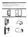
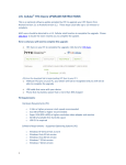
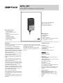
1 • DESCRIPTION FACEPLATE
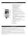
A - Indication of active outputs - Display state Out1,...,Out6
B - Indication of status instrument
RUN, ERR repetition of state of LEDs on Geflex
TUNE on if selftuning or autotuning is active
MAN on and control in manual state
REM on if remote set point is enabled
SP2 on if setpoint 2 is selected
DIG on if digital input is active
AL on if at least one alarm is active
N
C - PV Display: indication variable / parameter code
D - SV Display: indication variable value
A
C
D
E
B
F
G
H
L
I
M
E - Display of queried node
Meaning of flashing decimal points on ID display:
Both decimal points flash = serial dialog running
Only "ones" point flashes = data transfer to Geflex after "Load"
command
Only "tens" point flashes = first data read from Geflex at first
selection
Both decimal points off = serial communication absent (due to lack of
connection or incorrect ID address). In this case, the PV and SV values
are replaced by four segments “ - - - - “
F - “Lower” and “Raise” keys
Press to increment (decrement) any numerical parameter ••
Increment (decrement) speed is proportional to time key stays
pressed •• The operation is not cyclic: once the maximum (minimum)
value of a field is reached, the value will not change even if the key
remains pressed
G - “Function” key
Gives access to the various configuration phases
Confirms change of set parameters and browses next or previous
parameter (if Auto/Man key is pressed)
H - "Load" button, reads a configuration (loads the configuration from
GFX_OP in Geflex)
I - "Store" button, saves the configuration
L - Configurable key
M - Geflex Serial Cable
N - Winstrum Serial Cable
2 • OPERATING NOTES
N.B.: the GFX_OP terminal becomes the master when connected to Geflexes, and becomes the slave when connected to the Winstrum.
Recognition is at switch-on if it is connected to one of the two serial cables.
At power-up, the GFX_OP terminal turns on and tries to connect with the Geflex at the displayed ID address.
In the absence of a connection to display PV and SV, the indication “ - - - - " appears.
The parameters that can be displayed and/or set (Cod, BAu, PAr, Pro, but) reside in the terminal's EEPROM
memory.
When the connection is active (both decimal points on the ID display flashing), the data is automatically updated
with those contained in the connected Geflex.
Set the ID field with the "up" and "down" keys; if this corresponds to a Geflex in line, the connection will activate
with display of the process variable and setpoint, together with updating of the state by means of the faceplate
LEDs.
N.B.: the “LoAd” and “Stor” functions are active only in level 1 display when the process variable “PV” and active
setpoint “SP” are displayed.