1
User’s Manual
FP1800MBNC
TFT-LCD Monitor
Thank you for purchasing our Monochrome LCD
Display.
◆ Carefully read this User's Manual and use the
product properly. Before using it, also read
"Safety Precautions."
◆ Keep the User's Manual as close to you as
possible and in safe custody.
◆ If you have lost the manual, contact your dealer.
We will reissue a manual.
◆ The names of companies and products are
registered brand names or brand names.
Contents
1.Safety Precautions .................................3
2.Auxiliaries ...............................................7
3.Features .................................................8
4.Connection Method ..............................10
5.How to Operate ....................................14
6.Reference .............................................26
7.Applicable Signals ................................27
8.Failure Diagnosis..................................29
9.Cleaning ...............................................30
10.Specifications .......................................31
11.Technical Support .................................32
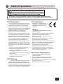
Safety Precautions
Attention, consult accompanying documents
Dangerous voltage, risk of electric shock
To reduce the risk of electric shock, do not remove the back cover.
No-user serviceable parts inside, refer to qualified service Personnel.
FCC Information
FCC (U.S.Federal Communications Commission)
This equipment has been tested and found
to comply with the limits for a Class B digital
device, pursuant to part 15 of the FCC Rules.
These limits are designed to provide reasonable
protection against harmful interference in a
residential installation. This equipment
generates, uses, and can radiate radio
frequency energy, and if not installed and used
in accordance with the instructions, may cause
harmful interference to radio communications.
However, there is no guarantee that interference
will not occur in a particular installation. If this
equipment does cause unacceptable interference to radio or television reception, which
can be determined by turning the equipment off
and on, the user is encouraged to try to correct
the interference by one or more of the following
measures:
- Reorient or relocate the receiving antenna.
- Increase the separation between the
equipment and receiver.
- Connect the equipment into an outlet on a
circuit different from that to which the receiver
is connected.
- Consult your dealer or an experienced
radio/TV technician for help.
FCC Warning:
To assure continued FCC compliance, the
user must use a grounded power supply cord
and the provided shielded video interface cable
with bonded ferrite cores. Also, any unauthorized
changes or modifications to this monitor would
void the user's authority to operate this device.
CE Certification
This device complies with the
requirements of the MDD directive
93/42/EEC "Medical Device
Directive".
Warning
- This apparatus must be earthed because of
Class I equipment.
- This apparatus is no patient contact equipment.
- When using at 240 V in United States,
supply must be from center-tapped, 240 V,
single phase circuit.
- Please consult with the dealer from whom you
purchased it about waste disposal.
- This equipment shall not to be used around the
patient vicinity, which is the space with surfaces
likely to be contacted by the patient or an
attendant who can touch the patient.
This encloses a space within the room 1.83 m
(6 feet) beyond the perimeter of the bed in its
intended location, and extending vertically 2.29
m (7-1/ 2 feet) above the floor.
Equipment Classification
- Type of protection against electric shock:
Class II equipment
- Protection against harmful ingress of water :
Ordinary Equipment (IPX0)-No protection.
- Not suitable for use in the presence of a flammable
anesthetics or oxygen.
- Mode of operation: Continuous operation
3
Follow the instructions below for safety use of the monochrome LCD display.
-Read this user’s manual and properly use the unit.
●Symbols
-This user’s manual contains various symbols to
guide users to properly use the product.
-The contents in each box below express the events
that will occur following neglects of signs and
misuse.
-Confirm the contents shown here and then read
this manual carefully.
Person could be at risk of severe
injury or death.
Warning
Person or properties could be at risk
of injury or damage.
Caution
●Meaning of symbols
Expresses DO NOT.
Expresses MUST DO.
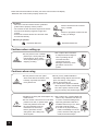
Cautions when setting up
Caution
●Do not put the unit on unstable
placees (on a wonky table and
inclined place), which might
cause injuries arising from its
dropping or falling.
●Do not place the unit where it
is subject to direct sunlight or
near any heating device.
The cabinet and/or
components may be
damaged, which may cause
generation of fever and
ignition.
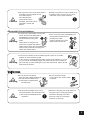
Cautions when using
Caution
4
●Do not put any metal materials or
flammable foreign objects into the unit
(from vent holes). It may lead to
electric shock and/or fire.
※ In case that any object mentioned
above is placed inside, immediately
turn off the power, disconnect the
plug from outlet, and contact shops.
●Scratching or hitting with hard objects may ●Do not place any container filled with
break the unit.
water or any chemicals near the unit.
●Do not use the unit turned over on its back, In case of containers falling down,
pushed on its side, or upside down.
liquid may permeate inside and
These may lead the fever that
insulation failure may occur, which
the unit generates to pile up
may lead to electric shock.
inside the unit, which may
※ In case of any liquid entering
lead to generation of fever
inside, immediately turn off the
and ignition. Also, falling may
power, disconnect the plug from
cause injuries.
outlet, and contact shops.
����
Warning
●Do not put the unit in such place
where it has bad air circulation, dust,
humidity, oily smoke and steam.
It may lead to fire.
Caution
●Do not put the unit in such place where it
is subject to direct sunlight or near
any heating device.
The cabinet and/or
components may be
damaged, which may cause
generation of fever and
ignition.
●During a long-hour use, take a break 10 to
15 minutes every one hour for your eyes.
Otherwise, it may cause eyestrain.
Abnormal circumstances
Warning
Warning
●In case of any abnormality such as odor,
sound, and overheat taking place,
immediately turn off the power
and disconnect the plug from
outlet.
Continuance of using the unit
under such condition may lead to
electric shock and/or fire. Immediately turn
off the power, disconnect the plug from
outlet, and contact shops.
●In the event of thunder, immediately turn
off the power and disconnect
the plug from outlet.
Lightning strikes may cause
electric shock and/or fire.
●In the event of broken panel and leaking liquid crystal, do not inhale,
swallow, or touch the liquid crystal.
It may cause you getting poisoned and/or having a skin irritation. If you put
it in your mouth, immediately gargle with water and go to see a doctor to
get a checkup. In case of taking it on your skin and/or cloth, wipe it off with
alcohol and rinse them.
Maintenance
Warning
Caution
5
●Do not remove the cabinet.
There are high-voltage parts inside
that may lead to electric shock.
※ Ask shops for adjustments
and inspection.
●Clean inside the display once a year.
The dust inside the unit may lead to fire.
※ Ask shops for adjustments and
inspection.
●Do not remodel or repair.
It may lead to fire, electric shock,
or injuries.
●Disconnect the plug from outlet when not
using the unit for a prolonged period.
Disconnect the plug from outlet
when not using for a prolonged
period for such as trip.
5
Notes
●Even if the unit is properly used, it may have an effect on radio and/or TV reception upon the
condition of electric wave. If it is the case, give caution to the followings.
1) Ensure enough space between the unit and radio and/or TV.
2) Connect the unit and radio and/or TV to separate outlets.
●Monochrome LCD display may have tiny spots and unevenness according to the displaying
conditions, but they are not any sign of failure.
●LCD panel is produced with high-definition technology, but there may be some imperfect
displaying pixels (lacking, constant lighting).
●When placing LCD panel near windows or outside for a long period of time, give caution to it;
sunlight may cause damage on the panel.
●Do not give LCD panel a strong push, scratch it, or place any object on it. It may cause LCD
panel failure.
●When using the unit in a cold place, you will see images leave traces or a dark screen, but it is
not a failure. It will go back to the normal state as temperature rises.
●Do not display still pictures for a long period of time, which may cause afterimages.
●The minimum state of the brightness adjustment may make images difficult to see.
●The quality of computer signals may have an effect on the unit’s quality. We recommend you to
select computers with high-quality video signal output.
●Instantaneous voltage change
This unit may have defects upon momentary voltage drops of power supply caused by incidents
such as lightning strikes. For the countermeasure for it, we recommend you to use devices such
as uninterruptive power supply.
Disposal of the unit
◆ Do not dispose of the unit with general wastes.
◆ Do not dispose of the unit together with general wastes.
◆ The unit contains mercury in its phospher tube. Follow your local regulations or rules upon disposal of
the unit.
6
Auxiliaries
Confirm the auxiliaries listed below are included.
□ Power cable
□ VGA analog signal cable
□ Composite video cable
□ S-Video cable
1
1
1
1
□ User’s Manual (this manual)
1
NOTES
* We recommend you to keep the packing box for transportation and the like.
* In case of transporting and packing the unit in the packing box, carefully place it, keeping its
panel from touching any objects.
7
Features
●18.1-inch LCD display with 1.3 million pixels
This monochrome LCD display has a multi-scanning function corresponding to the resolution from
VGA 640 x400 to SXGA1280 x 1024. This is also compliant with VESA standard display mode.
●High-intensity, high-contrast
Beautiful and clear images of the brightness of 700cd/m2 and contrast ratio of 700 : 1 have been
achieved. Viewing angles are the wide range of 170 degrees in both horizontal and vertical
directions (CR>=10). The unit has installed our unique automatic brightness stabilizing circuit that
restrains deteriorations and brightness drifts when power is turned on. Gamma curve adjustments
are made by OSD. This is for various modarity terminals, medical image displays for PACS *1, and
graphics.
●Internal power supply compliant with medical safety standards with high reliability
The monitor has an internal power supply that is compliant with UL2601 and TUV-GM.
●Support BNC input and interlace-timing
BNC input has been supported for replacement with a CRT used as a modarity device. It also
supports input modes: one line (Sync On Video), two line (Video, Composite Sync), three line
(Video, HD, VD). Interlace timing can be displayed.
●Two analog interfaces
This facilitates 15-pin Mini D-sub as well as BNC input, which supports signal inputs from
conventional PCs.
●Support TV signal input
Supporting TV signal inputs such as NTSC and PAL, the monitor can be used as a substitute
for conventional CRT monitors. The monitor is prepared for TV inputs such as composite input (Y
signal), S-Video input (Y/C), and component input (YCrCb). Thus, it can display various kinds of
images.
●PIP function
This monochrome LCD display has loaded the PIP (Picture In Picture) function that can partly
display TV inputs on screen besides displaying regular PC images.
●Remote control port
This monochrome LCD display has the remote control port that controls the functions of the
monitor via serial communication. A separate control software allows you to remote-control OSD
operations from your PC.
●User-friendly control dial and OSD
This monochrome LCD display can be handled by Control dial. This button not only rotates up and
down but also functions as a push button. Also, the on-screen display has an icon that is so
comprehensible that users can easily make settings.
●Power management
This unit has loaded the power management system. The power management mode functions
when either horizontal or vertical signals or both disappears, and it reduces power consumption to
less than 15W.
●PIVOT (combined vertical/horizontal display function)
The LCD panel can be used to display images in a vertical position by turning the panel
90 degrees from the horizontal position.
8
●VESA® standard wall/arm mountings
The unit is compliant with VESA's 100mm-pitch hanging tools. The tilt stand is detachable; the unit
can be set for wall-hanging or arm according to users' environment.
●Security device slot for Kensington® security system
Anti-theft security device slot has been loaded to correspond to MicroSave® security system of
Kensington®.
Note 1) PACS: Picture Archive & Communication System
9
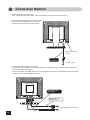
Connection Method
1. Confirm that your computer is off.
Then, confirm that the main switch of the monochrome LCD monitor on the back is off.
2. Connect the attached power cord into the inlet.
Then, connect the plug into the AC inlet on
the back of the monochrome LCD monitor.
Main Power Supply
Switch
Power cord
(accessory)
To power outlet
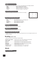
3. Connect the signal cable (for PC input)
Connect the VGA connector of the monitor and the analog RGB output connector with the attached
VGA cable (15-pin Mini D-sub).
For the connection with BNC connector, connect the BNC connector of the monitor and the PC’s video
output with a commercial BNC signal cable.
VGA signal cable
(accessory)
BNC signal cable
(commercial)
Analog RGB output of computer
10
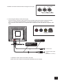
The BNC connection would look like in the figure on the right.
�������������
��
��
��
�����
4. Connect signal cable (for video device input)
Connect S-Video connector of the monitor and an S-Video output device with the attached S-Video
cable. For composite signal (NTSC/PAL) or component signal (Y-Cb-Cr) input, connect the
RCA connector of the monitor and a composite video output device with the attached composite video
cable.
��
��
�
��������
���������
�������
S-Video cable
(Accessory)
Composite video cable
(RCA plug x 3)
(Accessory)
S-Video source
Composite video output
device
(NTSC/PAL or Y-Cb-Cr)
A calibration sensor will be connected to PC-LINK.
Refer to the user's manual of the separate calibration kit for the details.
11
11
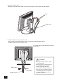
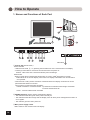
5. Remove the cable cover
Lifting the hook of the upper cable cover, slowly remove the cover to expose the cable holders.
Hook
Cable cover
6. Install the cable cover and connector cover
Secure cables to the cable holders on the back of the stand. (See the figure below)
Install the cable cover and connector cover.
It is free to arrange cable settings according to
environment.
Caution
������������
��������
�������������
12
●Do not give signal cables or power
cord a strong pull.
●A strong pull may cause damage on
the connection part inside the
display where high-precision
processing technology is applied. It
also may result in felling the display
and damaging on the LCD panel. In
the worst-case scenario, the LCD
panel will be broken.
7. Antitheft security device slot
This product has loaded an antitheft security device slot compliant with MicroSaver® Security System of
Kensington® on the back of the monochrome LCD display.
MicroSaver® security System can be purchased at PC supply shops.
®
* Kensington is a registered brand of Kensington
Antitheft security device slot
13
How to Operate
1. Names and Functions of Each Part
�
�
�
��������
���������
�������
�������
○
-
��
�������
15
�
�
�
�
�
��
��������
���������
�
��
�� ��
Alternative ��
① Control dial (Power switch)
Power ON/OFF
・ With the main swith, ③ , on, pressing Control dial turns on the monochrome LCD display.
・ Pressing Control dial for more than two seconds turns the power off.
Caution : Take more than 5 seconds between power switchings.
OSD control
・ When Control dial is pressed while images are on screen, OSD* will appear on screen.
*OSD stands for on-screen-display. Its function is to display information such as characters
and symbols.
・ Control dial is a rotary switch. Execution of selected items and display of submenus can be
performed while OSD is on screen.
Two functions of Control dial are as follows:
Rotate clockwise or counterclockwise : up-and-down movement/ left-and-right movement/
increase and decrease etc.
Press : execute/ select items/ save data
② POWER indicator (Power/ Power management display)
・ The indicator illuminates green when power normally on.
・ The indicator illuminates orange and the display turns off when power management function on
or no signals.
・ The indicator goes out when power off.
③ Main power supply switch
Main switch for the monochrome LCD display.
14
�������
�������������
�
④ AC inlet
Connect the attached AC cord to.
⑤ BNC connector_Sync On Video/Video
For one-line (Sync On Video) input, BNC connector is used as Sync On Video. For two-line
(VIDEO + composite sync signal) and three-line inputs, used as Video.
⑥ BNC connector_CS/HD
For two-line (Sync On Video) input, connect to CS (composite sync signal). For three-line (separate
sync signal) input, connect to HD (horizontal sync signal).
⑦ BNC connector_VD
For three-line (separate sync signal) input, connect to VD (vertical sync signal).
⑧ Analog input connector_VGA
Analog video signal input. The attached VGA analog signal cable is plugged into this to connect the
monitor and a computer.
⑨ S-Video input connector_VGA
S-Video signal input. The attached VGA analog signal cable is connected to this and an S-Video
output video device.
⑩ RCA input connector_Y
Composite brightness signal input. The attached composite video connection cable is connected to
this and a video output device.
⑪ RCA input connector_Cb
Composite B signal input. The attached composite video connection cable is connected to
this and a video output device.
⑫ RCA input connector_Cr
Composite R signal input. The attached composite video connection cable is connected to
this and a video output device.
⑬ RS232 Input / Output
Firmware update.
⑭ DVI connector
Digital video signal input. The attached DVI digital signal cable is plugged into this to connect the
monitor and a computer.
15 Video-Term
ON: Sync on video.
OFF: Connect with other monitor serially.
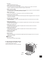
2. Adjusting the Display Angle
Tilt
The best display angle is head-on.
Make tilt arrangements to obtain the best angle.
6°
20°
90°
Pivot
140°
Swivel
15
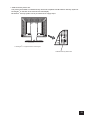
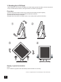
3. Rotating the LCD Panel
When setting the monochrome LCD display to vertical display (portrait orientation), lift the LCD panel to
the top of the tilt stand as shown in the figure below and rotate it by 90 degrees.
Procedure
① Tilt the LCD panel upward. (Perform this procedure before sliding the panel upward.)
② Lift the LCD panel to the top (The tilt stand will slide about 50mm.).
③ Rotate the LCD panel by 90 degrees.
④ Replace the LCD panel to the bottom while in the vertical position (portrait orientation).
①
②
③
④
Display in portrait orientation
Pivot,,,
Pivot® software or graphics card that enables portrait orientation is necessary.
®
* Pivot is a registered brand of Portrait Displays of the United States.
16
4. OSD Adjustments
The unit has loaded adjustment functiona through OSD to perfectly display video signal input. Operating
the control dial on the back of the monochrome LCD display enables to make settings and adjustments for
selected items.
Notes
����
�
�������
�����
Items adjusted and setting values are shown on
screen. OSD stands for on-screen-display.
Its function is to display information such as
characters and symbols.
This OSD is normally displayed in the center of
the screen, but it is alterable.
However, the size of the OSD display is not
adjustable since it is automatically adjusted by
signal timing.
���
���������
����������
���
�������
������������������
����
�����������������
�������
����������������
��������
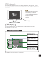
OSD display
OSD Display
The OSD menu is displayed with icons, adjustment items, and setting values as shown below.
(The figure below is the main menu.)
Main Menu Display
Adjustment item icons
Icons of adjustable items
�
Cursor display
The menu pressed will be
shown.
����
���
�������
���������
�����
����������
���
�������
Input selection and timing
Display input connector and
input timing currently selected.
������������������
����
�����������������
�������
����������������
��������
Signal timing number
The number previously preset
will be shown (user can't
change it).
OSD adjustment screen has "main menu" and "submenus."
17
17
Charts of OSD Adjustment Functions
The chart below displays the function tree and brief explanations of the functions. Color, LCD, and other
adjustments have submenus under each tree.
●OSD display
Main Menu display
・ Exit.............................................Close the OSD screen
・ Picture
- Return To Main Menu............Return to Main Menu
- Auto Adjustment...................Automatically adjust the display
- Brightness.............................Adjust the brightness of the full screen at the range from 0 to 100
- Contrast.................................Adjust the contrast of the full screen at the range from 0 to 100
- Black Level............................Adjust black level
- Gamma
- 1.6..................................Gamma, 1.6
- 1.8..................................Gamma, 1.8
- 2.0..................................Gamma, 2.0
- 2.2..................................Gamma, 2.2
- 2.4..................................Gamma, 2.4
- DICOM............................Gamma value set as the medical standard
- User 1.............................User set gamma value
- User 2.............................User set gamma value
- User 3.............................User set gamma value
- User 4.............................User set gamma value
- Color compatible
- Normal...........................Normal display mode (input the same signals to each R,G, and B)
- Color compatible..........Color compatible gradation (contrast calibration for color images)
- User
- Exit..........................Return to Picture Menu
- R.. ...........................User adjusts the intensity of Red channel at the range from 0 to 100
- G.............................User adjusts the intensity of Green channel at the range from 0 to 100
- B.............................User adjusts the intensity of Blue channel at the range from 0 to 100
- Clock...................................Fine adjustments on horizontal position of video signals
- Phase..................................Phase adjustments
- Sharpness..........................Five-step adjustments from soft to sharp of character outline
- H.Position...........................Adjust horizontal screen position
- V.Position............................Adjust vertical screen position
・ Input
- Exit........................................Return to Main Menu
- Auto
- Exit.................................Return to Input menu
- Auto 1.. ..........................Full-time input signal detection mode
- Auto 2.............................Start-up input signal detection mode
- VGA.......................................Select 15-pin Mini D-sub input signals
- BNC.......................................Select BNC input signals
- S-Video..................................Select S-Video input signals
- Composite............................Select composite input signals
- Y Cb Cr..................................Select component input signals
18
・PIP(Picture in Picture)
Return To Main Menu...........................Return to Main Menu
PIP Size
OFF.................................................Not display PIP
Small..............................................Display PIP small
Medium..........................................Display PIP in normal size
Large..............................................Display PIP in large size
PIP Position..........................................Select PIP position from the nine point of the screen
PIP Source
Auto................................................Automatically select PIP input signals
S-Video...........................................Set PIP input signals S-Video
Composite.....................................Set PIP input signals composite
YCbCr.. ..........................................Set PIP input signals YCbCr
PIP Contrast..........................................Adjust PIP contrast
PIP Black Level.....................................Adjust PIP Black level
PIP Sharpness ......................................Calibrate outline of the PIP image
・ Scaling
Maintain Aspect Ratio ........ Full-screen display (maintain aspect ratio)
ONE to ONE ........................ Display actual resolution
FULL 5:4 .......................... Full-screen display of images with aspect ratio, 5:4
FULL 4:3 ..............................Full-screen display of images with aspect ratio, 4:3
FULL 16:9.............................Full-screen display of images with aspect ratio, 16:9
16:9)
4:3 to 16:9............................ Change aspect ratio of images (4:3
Letterbox to 16:9 ................ Display letterbox images with aspect ratio, 16:9
Letterbox to 4:3 .................. Display letterbox images with aspect ratio, 4:3
・Zoom
Return To Main Menu.. ........................Return to Main Menu
Zoom In ................................................Zoom image
Horizontal Panning..............................Horizontally pan zoomed image
Vertical Panning ..................................Vertically pan zoomed image
・Utility
Return To Main Menu ......... Return to Main Menu
Key Lock ............................. Display OSD Lock
OSD Horizontal Position .... Adjust horizontal position of OSD
OSD Vertical Position.........Adjust vertical position of OSD
Multi Language
English..........................Display OSD in English
Deutsch.........................Display OSD in German
Francais .......................Display OSD in French
Italiano .........................Display OSD in Italian
~ ........................Display OSD in Spanish
Espanol
^ ....................Display OSD in Portuguese
Portugues
OSD Background
Translucent .................. Display OSD in see-through background
Opaque ......................... Display OSD in black background
OSD Display Timer ............. Adjust time to display OSD
EPA Power Saving
ON ..................................Turn on power management
OFF ................................Turn off power management
Auto Setup Function...........VGA / BNC auto setup ON/OFF
Restore To Factory
Default Setting ............. Restore to factroy setting
19
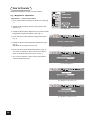
How to Operate
Adjustment examples from the main menu below.
�
e.g., "Brightness" adjustment
Adjustment 1…from the main menu
1. Press Control dial and display the OSD menu (See Fig.
1).
����
���
�������
���������
�����
����������
���
�������
2. Rotate the dial to select "Picture" and press the dial.
(See Fig. 2).
������������������
����
�����������������
�������
����������������
��������
Fig.1 Main menu
3. Rotate the dial to select "Brightness" and press the dial.
("Brightness" display will appear) (See Fig. 3).
•••••
••••
4. Press the dial to make brightness adjustments (See
Fig. 4).
Return To Main Menu
5. Rotate the dial to make brightness adjustments (See
Fig. 5).
Adjustable at the range from 0 to 100.
6. Press the dial to finish adjustments (return to Fig. 2).
The cursor is placed on "Exit." Press Control dial to
return to the OSD main menu (return to Fig. 1).
Fig.2 Select "Picture"
•••••
••••
Brightness
7. The cursor is placed on "Exit." Press Control dial to
close the OSD main menu.
60
Fig.3 Select "Brightness"
•••••
••••
Brightness
60
Fig.4 "Brightness" adjustment menu
•••••
••••
Brightness
71
Fig.5 "Brightness" adjustment menu
20
Details of Adjustment Items
The adjustment functions are described as follows.
Exit
Close the OSD main menu.
Picture
(adjust images)
Return To Main Menu
Return to the main menu.
Auto adjustment (automatic adjustment)
Automatically adjust the size, position, brightness, contrast, and the like of the screen. When first using
this monochrome display or inputting new timings, perform this adjustment.
【Caution】
In order to make this properly work, display application such as word processing or spreadsheet
software on full-size screen or one close to it. This may not work properly with MS-DOS screen.
《 Procedure 》
1. Select "Auto adjustment" and press Control dial.
2. Make adjustments, If flickers, flurs, or small horizontal stripes appears on screen (See "Phase" on
page 20).
If partially phased screen is observed on screen, make fine adjustments on video signal position to
horizontal synchronized signals by rotating the control knob. (See "Clock" on page 20)
Brightness (adjust brightness)
Adjust brightness of the screen. The larger the value is, the brighter the screen is, and vice versa.
Adjustable at the range from 0 to 100 by a couple of steps.
Contrast (adjust contrast)
Adjust contrast of the screen. The larger the value is, the stronger the contrast is, and vice versa.
Adjustable at the range from 0 to 100 by a couple of steps.
Black Level (adjust black level)
Adjust black level of the screen. The larger the value is, the brighter the brightness of the background
contrast is, and vice versa. Adjustable at the range from 0 to 100 by one.
Gamma (adjust gamma)
Adjust gamma values as follows.
● 1.6 ......................set gamma to 1.6
● 1.8 ......................set gamma to 1.8
● 2.0 ......................set gamma to 2.0
● 2.2 ......................set gamma to 2.2
● 2.4 ......................set gamma to 2.4
● DICOM .................set gamma set for medical standards
● User 1 .................set gamma value set by user.
● User 2 .................set gamma value set by user.
● User 3 .................set gamma value set by user.
● User 4 .................set gamma value set by user.
21
Color Compatible (color compatibility)
User can make tone adjustments and settings.
●Normal ............... Normal display mode. Maximum brightness is available as a result of inputting the
same signals to each R, G, and B.
●Color compatible...........Highlight contrast in monochrome display. Used for verification of tones in
R, G, and B. (do not operate in BNC input)
●User ................... User can adjust and set tones.
●Exit............... Return to Picture Menu.
●R................... Adjust red and equivalent colors at the range from 0 to 100. The greater the value
is, the deeper the color is, and vice versa.
●G................... Adjust green and equivalent colors at the range from 0 to 100. The greater the
value is, the deeper the color is, and vice versa.
●B................... Adjust blue and equivalent colors at the range from 0 to 100. The greater the value
is, the deeper the color is, and vice versa.
Clock (clock adjustment)
When operating "Auto adjustment" and if any partially phased screen, make fine adjustments on video
signal position to horizontally synchronized signals by rotating the control knob. As the value gets larger,
the screen moves to the right, and vice versa. Adjustable at the range from 0 to 100.
Phase (phase adjustment)
Make "Phase" adjustments, if any flickers, blurs, or horizontal stripes on screen. Adjustable at the range
from 0 to 100.
Sharpness (correct outline)
Five-step adjustments for outline correction is available according to display resolution.
As the value gets larger, the outline gets sharper, and vice versa.
To make characters look shaper, set a large value. To make pictures and images look finer, set a small
value.
H-Position (horizontal position adjustment)
Adjust the horizontal position of the display. When rotating Control dial clockwise, the display moves to
the left, and vice versa.
V-Position (Vertical position adjustment)
Adjust the vertical position of the display. When rotating Control dial clockwise, the display moves
upward, and vice versa.
22
Input
Exit
Return to the main menu.
Auto (detect input signal)
Set detection mode to detect input signals.
●Exit.......................Return to Input menu.
●Auto 1.................. Full-time input signal detection mode. When currently used signals have no input
with more than two lines used, this function automatically detects such an event
and switches to other line that has input signals.
●Auto 2...................Start-up input signal detection mode. Only at the time of start-up, this automatically
detects whether input signals are present. After start-up, manual operation is
available. This function can be selected when user wants video signals
consistently from one computer or does not want automatic switching as described
in Auto 1.
VGA
Display signals from VGA connector (15-pin Mini D-sub).
BNC
Display signals from BNC connector. Inputs are as follows.
●One-line Sync On Video input.............VIDEO
●Two-line input ............ ..........................VIDEO + CS (HD)
●Three-line input ......... ..........................VIDEO + CS (HD) + VD
S-Video
Display signals from S-Video connector.
Inputs in which brightness signals, Y, and color-difference signals are separate can display images with
higher resolution than that of Y signals.
Composite
Display signals from composite connector (RCA connector). Only Y input is available.
Y Cb Cr
Display signals from component connector (RCA connector). Three video inputs: brightness signals (Y),
R color-difference signals (Cr), B color-difference signals (Cb) are available.
PIP
(Picture In Picture)
This monitor has loaded the PIP (Picture In Picture) function that can display video signals (Y, YCbCr,
S-Video signals) on part of the screen when displaying input signals from BNC or VGA (15-pin Mini
D-sub). This is available, only when BNC or VGA (15-pin Mini D-sub) is selected and fixed.
Return To Main Menu
Return to the main menu.
23
PIP Size
Select display size of the PIP image. The size varies depending on the display resolution.
●OFF.......................................Does not display the PIP image.
●Small.....................................Display PIP images in a small scale.
●Medium.................................Display PIP images in the regular scale.
●Large.....................................Display PIP images in a large scale.
PIP Position (PIP display posiion)
Select the PIP position from the nine points as shown on the right.
1
2
3
4
5
6
7
8
9
PIP Source (PIP display input selection)
Select PIP display input from the followings.
●Auto ............................ Set automatic selection for PIP display input.
●S-Video ....................... Set PIP display input S-Video.
●Composite.................. Set PIP display input composite.
●YCbCr ......................... Set PIP display input YCbCr.
PIP Contrast
Adjust PIP contrast at the range from 0 to 100.
PIP Black Level
Adjust PIP black level at the range from 0 to 100.
PIP Sharpness (PIP outline calibration)
Calibrate outline of the PIP image. Adjust it at the range from 0 to 100. The larger the value is, the
shaper the image is.
Scaling
(adjust scale)
Select one scale from the followings to display images.
Maintain Aspect Ratio....... Display full-size screen with maintaing the aspect ratio.
ONE to ONE ....................... Display images with the actual resolution.
FULL 5:4 ......................... Display images of 5:4 aspect ratio in full-size screen.
FULL 4:3 ........................... Display images of 4:3 aspect ratio in full-size screen.
FULL 16:9 ........................... Display images of 16:9 aspect ratio in full-size screen.
4:3 to16:9 ........................... Display images of 4:3 in 16:9.
Letterbox to 16:9 ............... Display letterbox images in 16:9 aspect ratio.
Letterbox to 4:3 .................Display letterbox images in 4:3 aspect ratio.
Zoom
Return To Main Menu
Return to the main menu.
24
Zoom In (expand iamges)
Zoom images currently on screen.
【Caution】 The images zoomed will return to the original state when the power of the monochrome
monitor is turned off.
Horizontal Panning
Pan the zoomed images horizontally.
【Caution】 The panned images will return to the original state when the power of the monochrome
monitor is turned off.
Vertical Panning
Pan the zoomed images vertically.
【Caution】 The panned images will return to the original state when the power of the monochrome
monitor is turned off.
Utility
Return To Main Menu
Return to the main menu.
Key Lock
Display OSD lock.
OSD Horizontal Position
Adjust the horizontal position of OSD. When rotating Control dial clockwise, OSD moves to the right, and
vice versa.
OSD Vertical Position
Adjust the vertical position of OSD. When rotating Control dial clockwise, the display moves downward,
and vice versa.
Multi Language
Select an OSD language out of six languages below.
English .............................. English
................................ Japanese
Deutsch ............................ German
Fran çais ........................... French
Italiano .............................. Italian
Espa ñol ............................ Spanish
Portugues .........................Portuguese
OSD Background
Select the background of OSD from black background and see-through.
Translucent .............................See-through display.
Opaque ....................................Black background display.
25
OSD Display Timer
Set a time period of OSD display from 0 to 255 seconds by one second.
When "0 (zero)" is chosen, OSD will keep appearing on screen until "Exit" is pressed.
OSD will automatically disappear after the time set has passed if the timer is set from 1 to 255 seconds.
EPA Power Saving
Select the power management function to save power.
ON......................................Turn on the power management.
OFF ....................................Turn off the power management.
BNC Auto Setup Function
xxxxxxxxxxxxxxxxxxxxxxxxxxxxxxxxxxxxxxxxxxxxxxxxxxxxxxxxxxxxxxxxxxxxxxxxxxxxx
xxxxxxxxxxxxxxxxxxxxxxxxxxxxx
Restore To factory Default Setting
Initialize the data such as display position and automatic adjustment data to factory default. After
initialization, perform "Auto Adjustment" again.
26
Reference
DDC*1
◆ This unit has loaded a function compliant with DDC-2B, VESA*2 standard.
The DDC function is located in 15-pin D-sub connector and 24-pin DVI-D connector.
This function reads into the set data written in the monochrome LCD display internal device in advance
on start-up of Windows®95/98/Me/2000 or Windows®XP and sets the detailed information of the
monochrome LCD display in the system file in order to achieve Plug&Play.
Data reading from the monochrome LCD display is done through a video signal cable, which needs to
be connected when Windows®95/98/Me/2000 or Windows®XP is on.
Note
*1
DDC(Display Data channel) and *2VESA are registered trademarks of Video Electronics Standards
Association.
Power Management
What is power management?
This is the function that truns off the screen by detecting input signal change to reduce power consumption
for power saving.
Setting
Refer to the user's manuals of your computer and display drivers for DPMS*3 settings and time-settings for
mode change.
Note
*3
DPMS stands for Display Power Management Signaling.
27
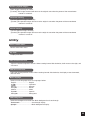
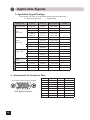
Applicable Signals
1. Applicable Signal Timings
※ The display may not work correctly with timings other than listed below.
◎ : Recommended timing
◯ : Applied timing
Display mode
VGA 640 x 480
VGA
640 x 480
V
SVGA
800 x 600
E
S
A XGA
1024 x 768
SXGA
1280 x 1024
TV
in
NTSC
PAL
Horizontal
frequency
Vertical
frequency
Pixel frequency
Remark
31.47 kHz
70.09Hz
25.175 MHz
○
31.47 kHz
59.94 Hz
25.175 MHz
○
37.50 kHz
75.00 Hz
31.50 MHz
○
37.86kHz
72.81 Hz
31.50 MHz
○
43.27 kHz
85.01 Hz
36.00 MHz
○
35.16 kHz
56.25 Hz
36.00 MHz
○
37.88 kHz
60.32 Hz
40.00 MHz
○
48.08 kHz
72.19 Hz
50.00 MHz
○
46.88 kHz
75.00 Hz
49.50 MHz
○
53.67 kHz
85.06 Hz
56.25 MHz
○
48.36 kHz
60.00 Hz
65.00 MHz
○
56.48 kHz
70.07 Hz
75.00 MHz
○
60.02 kHz
75.03 Hz
78.75 MHz
○
68.68 kHz
85.00 Hz
94.50 MHz
○
60.02 Hz
108.00 MHz
◎
63.98 kHz
75.03 Hz
135.00 MHz
15.73 kHz
59.94 Hz
14.32 MHz
Interlace display
15.63 kHz
50.00 Hz
17.73 MHz
Interlace display
79.98 kHz
○
put
2. Assignment of Connector Pins
15-pin Mini D-sub Connector (female)
� � � � �
�� � � � �
�� �� �� �� ��
VGA signal connector
28
Pin #
Signal
Pin #
1
S1(R:Red)
9
Signal
-
2
S2(G:Green)
10
HS-GND
3
S3(B:Blue)
11
VS-GND
4
GND
12
DDC,SDT
5
GND
13
HS
6
S1-GND
14
VS
7
S2-GND
15
DDC,SCLK
8
S3-GND
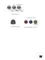
��
��
�������������
��
�����
BNC Connector
RCA Connector (female)
��
�
��������
���������
��
�������
S-Video Connector
��
�
��������
���������
�������
Component Signal Connector
29
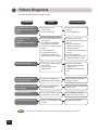
Failure Diagnosis
Check the followings before requesting repair.
Symptom
Countermeasure
Power doesn't turn on!
(POWER indicator doesn't
light!).
a: Is the power cord
connected?
b: Is the power ON?
a: Connect the power cord (see
pg.10).
b: Turn the power on.
The screen is not
displayed! *
(POWER indicator lights
up).
a: Is the signal cable properly
connected?
b: Is contrast or brightness
adjustment at minimum?
c: Is it under the power saving
mode?
d: Is the system on?
e: Is the signal input an
applicable one within the
stipulated frequency range?
a: Properly connect the
appropriate signal cable (see
pg. 10).
b: Adjust contrast and
brightness (See pg. 21).
c: Cancel the power
management mode (See pg.
25,26).
d: Turn the system on.
e: Input the applicable signals
within the frequecy range.
Colors look strange!
a: Is the signal cable properly
connected?
b: Did you make color
adjustments?
a: Properly connect the
appropriate signal cable
(See pg. 10).
b: Readjust colors (See pg.
22).
Display size and position
are not appropriate!
a: Is the preset adjusted to
comply with input signals?
a: Make display adjustments
(See pg. 21~25).
The display is dark (bright)!
Or, saturated!
a: Is the input video signal
level appropriate?
a: Make automatic adjustments
(See pg. 21).
The display vibrates!
Control dial doesn't work!
Note
30
29
Verify
a: Is any signal that is out of the
set frequency range input?
a: Are you not rotating the dial
so fast?
a: Input applicable signals
within the frequecy range.
a: Rotate the dial slowly.
*: Signals from computers may not come into when power management function is on.
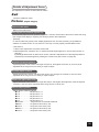
Cleaning
Cleaning the Cabinet and the Monochrome LCD Display
●When cleaning, remove the AC adapter from the monochrome LCD display and outlet for
safety.
●Lightly wipe off dirt on the cabinet and LCD panel surface with a hard-wrung soft cloth soaked
in a neutral cleaning solution. Follow its instruction when using a disposable cloth.
●Do not use thinner, benzine, alcohol or such on the cabinet that is made of plastic. These can
damage the cabinet, alter its quality and cause the paint to peel off.
●Do not apply insecticides and other volatile items to the cabinet. Also do not leave rubber and
vinyl products or such in contact with it for long hours. This can cause the quality to alter and
the paint to peel off.
●Cleaners usable for the monochrome LCD panel are isopropyl alcohol (without abrasive),
non-ammonic glass cleaner, and watered-down neutral cleaning solution. Do not use organic
solvent such as acetone and toluene.
●When the screen has dust on the monochrome LCD panel surface, wipe it off with soft moist
cloth.
●Treat the monochrome LCD panel with care. Do not rub the LCD panel surface with a
rough item or hit it on the surface. Also, do not strongly press the LCD panel surface. This can
lead to unevenness in the screen and also to failure of the product.
31
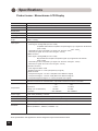
Specifications
Product name : Monochrome LCD Display
Specifications
Items
LCD display device
46cm (18.1 inch) Monochrome TFT Normally Black
Pixel pitch
Horizontal 0.2805 mm × Vertical 0.2805 mm
Display area
Horizontal 359.0 mm × Vertical 287.2 mm
Pixel
1280 × 1024 pixels
Display gradation
256 (8 bit) x 3
S t a n d a r d v i e w i n g Horizontal : 170 deg.
angle
Vertical : 170 deg.
Input signal
(1) VGA (15-pin Mini D-sub) connector
Video signal : Analog RGB (0.714VP-P/75Ω)
compatible with RS-343-compliant composite signal, sync signal from S2 terminal
(0.3VP-P/75Ω)
Horizontal sync and composite sync signal: TTL level 2.5~5.5V(plus ・ minus)
Vertical sync signal: TTL level 2.5~5.5V (plus ・ minus)
(2) BNC connector
Video signal : Analog RGB (0.714VP-P/75Ω)
Support RS-343-compliant composite signal. Sync signal from S2 terminal
(0.3VP-P/75Ω)
Horizontal sync and composite sync signal: TTL level 2.5~5.5V(plus ・ minus)
Vertical sync signal: TTL level 2.5~5.5V (plus ・ minus)
Input terminal
(3) S-Video connector
Color signal: 0.286VP-P/75Ω
Brightness signal: 1VP-P/75Ω (composite sync signal)
(4) RCA connector
Component R signal: ± 0.35VP-P/75Ω (Red color-difference signal)
Component B signal: ± 0.35VP-P/75Ω (Blue color-difference signal)
Composite brightness signal: 1VP-P/75Ω (composite sync signal)
15-pin mini D-sub connector, BNC connector, RCA (YCbCr) connector, S-Video connector,
8-pin serial connector for communication, 8-pin serial connector for sensor connection
On
Temperature
Temperature
Humidity (non-condensation)
Air pressure
Power supply
AC100~240V (50/60Hz), 1.2A Max.
:
5~35℃
: 20~80%
: 697~1060hPa
Off
-20~60℃
10~90%
187~1060hPa
Consumption current Approx. 60W Max. /Less than 8W when power management on
External dimensions Width 432 mm x Depth 251 mm × Height 466 mm (landscape)
Mass
Approx. 9.2kg (net weight)
International
standards
UL60601-1, CSA C22.2 N601.1, FCC Part15 ClassB, DOC-B,
MDD/CE (EN60601-1, EN55011, EN60601-1-2)
●The specifications and appearance will be changed for improvement without notice.
32
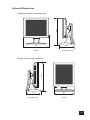
External Dimensions
���
Landscape (longer side at the top)
���
���
【Right side view】
【Front】
-
���
�������
��������
���������
�������
��
������
○
Portrait (shorter side at the top)
���
【Left side view】
���
【Front】
33
Technical Support
Requesting Repair
① Read "Failure Diagnosis (Pg. 29)" carefully and check them yourself.
② In case of having abnormalities on your driver, stop operating, unplug the AC cable from the outlet, and
consult dealer.Do not repair by yourself. It is very dangerous.
③ Consult dealer for repair.
④ Use the product's packing and packing materials to send the product. Carefully place the unit in the
packing, and keep the face from touching any packing materials.
The panel surface touching the materials during transportation will cause damage on the panel surface;
we will not cover the damage.
Contact Technical Support
Teklink Service.(Refferred to on the next page)
Notes for User's Manual
・ It is prohibited that copying any part or all of this manual without authorization.
・ The content of this manual will be subject to change without notice.
・ This was made carefully. Please contact us if any unclear points, mistakes, or parts left out.
34
Comprehensive Technical Support
• 24X7 Internet and phone service
• Multiple on-site options
• Installation and problem resolution
• Consulting, training and maintenance
Learn more at teklink.rell.com
Richardson Electronics Ltd.
Display Systems Group – Healthcare
12975 16th Avenue N.
Suite 300
Plymouth, MN 55441
Phone: 763-550-9001
Toll Free: 888-735-7373
web: www.imagesystemscorp.com
MDLIPPR010