1
Cleveland Motion Controls
QUANTUM
USER MANUAL
MAN-70421
TENSION CONTROL
Congratulations on your Cleveland Motion
Controls Quantum digital controller!
You have just acquired the most user friendly
and powerful digital controller in its
category.
This user manual has been designed to give
you all the information you need for
installation and commissioning.
CONTENTS
Dimensions - Mounting
3
Basic wiring
4
Setting up - Overview
4
Typical application examples
5
Wiring for l or z transducers - Classic or Ultra
9
Keyboard basics
10
Full programming principles with front face keyboard
11
PC software - Installation and Use
13
Parameter Setup; Menu Selection; Digital I/0; Help notes:
-1.0 Parameters
-2.0 Menu Inputs
-3.0 Menu Display
-4.0 Menu Functions
-5.0 Menu PID
-6.0 Menu Outputs
-7.0 Digital Inputs
-8.0 Data Capture
14
2
www.cmccontrols.com
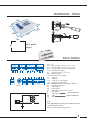
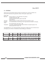
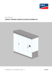
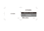
DIMENSIONS - FIXING
166
4
111
38
1 - 5 mm
100
2
15
156
101
Front panel
cutout
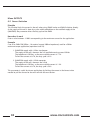
BASIC WIRING
+24
Com
output
control
logic
inputs
alarms
Primary
Supply
fuse
3.15A T
Secondary
supply
Reg
+5V
S1+
V+
F
init
S1-
B
V+
A
Com
measurements
+24V
DM
AL2
TC
Com
AL1
Com
AL-
C1
+10V
tacho /
diameter
C2
Com
A02
A01
Com
Com
+24
Com
SetP
set
point
analog
outputs
Com : 0 V
A01 : analog output control 1 (-10 to +10 V)
A02 : analog output control 2 (-10 to +10 V)
SetP : set point input (0 to 10V, or potentiometer)
+10V : potentiometer supply
TC
: tachometer input (0 to 10 V)
DM : diameter input
+24V : Ultrasonic sensor supply
S1: Signal (-)
S1+ : Signal (+)
+5V : load cell or sensor supply
+24 : supply (24 V AC or DC)
C1-C2 : PWM output (brakes direct supply) 1.5 Amp max.
AL- : ouptut logic reference
AL1 : logic output 1
AL2 : logic output 2
V+
: logic input voltage remote control
A
: logic input 1
process configuration
B
: logic input 2
init
: INIT
regulator configuration
reg
: REG
Note :
When grounding the secondary of the transformer, please
refer to the opposite sketch.
All Com / 0V are linked to the ground
3
OVERVIEW
User friendly
Selectable language (En / Fr / Ge / It)
Selectable Metric or Imperial units
HOLD and RELEASE on front panel keyboard
Advanced regulation capabilities
Automatic P.I.D. parameters variation function
Closed loop + open loop mode
Inertia compensation control
Smooth start-up with programmable slope
E-stop torque proportional to the set point
Adjustable tapper function available
No-Stop web turrets management function
Five complete built-in memories
Motors & Drives specific settings available
Fully compatible with
Any current load cell technologies
One or two, half or full bridge load cells
US sensors (direct input available)
Built-in PWM Power Supply
Up to 1.5 Amp available as PWM output voltage
No need for external power supply with EMAG Brakes
All details about these advanced features are
fully available in the Help file included with the
PC software supplied with the unit.
PC software sett-up and debugging
Unlimited configuration records by software
Real time full control panel available
Unlimited real time data record by software
SETTING UP
Two different ways are offered for system set-up of
your QUANTUM:
Using the exclusive user friendly set-up software
(QUANTUMsoft on a computer.)
Choose the required type of application, fill in
the datafields with your own data, and upload
the file to the QUANTUM.
At any point in the set-up you can click on help
in the toolbar, which gives you more details
about the procedure.
Using the front face keypad when there is no
computer available (password requested, see
p10).
The procedure is based on the “Initial set of
parameters” related to each type of application
(on pages 5-8). Enter the data as per the drawing
on p10.
System set up procedure to be followed
1 - Sensor(s) calibration
Follow the automatic calibration procedure
Software : Download the related “.prm” file
See -> Input Menu in the
QUANTUMsoft and enter the data
fields related to the chosen
application
4
Keypad :
Follow -> Input > Measure > ... (load cells)
Follow -> Input > Diameter > ... (US
sensor)
2 - Set point value
Open loop: enter a percentage of the full scale
Closed loop: enter directly the target value
Note:
The Set Point value can be adjusted at any
time from the front panel keypad
3 - Input/Output definition
Software:
See -> Input and Output Menus and
enter the data fields related to the
chosen application
Keypad:
Enter the parameters shown on the table
4 - Dynamic parameters (regulation and stability)
Software:
See -> Regulation Menu and enter the
data fields related to the chosen
application
Keypad:
Enter the parameters shown on the table
www.cmccontrols.com
Stability:
When necessary adjust the parameters
(*) to improve the system stability
Troubleshooting
Note:
Variable
PID
(coefficients
are
proportional to the diameter) is also
available when system stability cannot
be obtained (diameter measurement
must be available).
Detailed features about the Variable
PID are fully available in the Help file
included to the PC software
Check:
CAUTION:
All wiring, in particular ensure cable
shields are properly connected
Ensure the parameter settings are in
full accordance with the related
applications tables
Ensure the required “Process” (link
to the machine automation) is
active before starting the system
(logic input B)
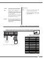
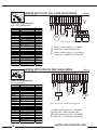
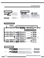
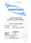
TYPICAL APPLICATION EXAMPLES
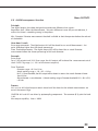
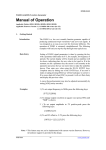
WIRING UNWIND WITH EMAG BRAKE AND ULTRASONIC SENSOR
DM
+24
Com
Reg
Init
V+
B
A
V+
C2
C1
+24
Com
OPEN LOOP
Initial set of parameters
File : Diameter_measurement.prm
Blue
Bleu
Yellow
Jaune
Brown
Brun
Jumper
+24 V
AC / DC
EMAG
Brake
S
+
NR7
Ultrasonic
Sensor
Note : all Com / 0V are linked to the ground
DISPLAY
Line 1
Line 2
FUNCTIONS Time Delay Start
Time Delay Stop
Hold
INPUTS
Set Point
Diameter Filtering
Tachymeter Filtering
OUTPUTS
Upper Limit
Bottom Limit
Power Gain
REGULATION Max Effort
P
I
D
Measurement Filtering
Open Loop Gain
Closed Loop Gain
Speed Gain
Coeff Speed
Overspeed
Set Point
Diameter
50
1000
0
10
100
100
100
5
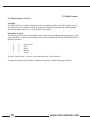
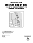
UNWIND WITH LOAD CELLS AND EMAG BRAKE
Wiring
+5V
S1+
Com
S1-
Reg
Init
V+
B
A
V+
C2
C1
+24
Com
CLOSED LOOP
Other
load
c e l l s
configuratios,
see page 9
*
Initial set of parameters
File : Force_feedback.prm
0
10
100
100 (*)
20 (*)
0
100 (*)
0
100
0
Jumpers
Logic
input B
N.O.
EMAG
Brake
Load cell
Classic
R
R
BK
WH
+24 V
AC / DC
WH
Set Point
Measure
1
300
10
50
BK
Line 1
Line 2
FUNCTIONS Time Delay Start
Time Delay Stop
Hold
INPUTS
Set Point
Diameter Filtering
Tachymeter Filtering
OUTPUTS
Upper Limit
Bottom Limit
Power Gain
REGULATION Max Effort
P
I
D
Measurement Filtering
Open Loop Gain
Closed Loop Gain
Speed Gain
Coeff Speed
Overspeed
Load cell
Classic
Note : all Com / 0V are linked to the ground
Process
DISPLAY
Machine / product stopped : B = 0V (OPEN)
Web Tension = HOLD value (Open Loop)
Machine / product running : B = 24V (CLOSED)
Web Tension = SET POINT value (Closed Loop)
0
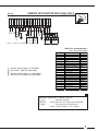
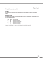
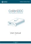
UNWIND WITH DANCER AND EMAG BRAKE
Wiring
+5V
S1+
Com
S1-
Reg
Init
V+
B
A
V+
AO2
AO1
Com
Com
+24
Com
CLOSED LOOP
Initial set of parameters
File : Dancer.prm
Line 1
Line 2
FUNCTIONS Time Delay Start
Time Delay Stop
Hold
INPUTS
Set Point
Diameter Filtering
Tachymeter Filtering
OUTPUTS
Upper Limit
Bottom Limit
Power Gain
REGULATION Max Effort
P
I
D
Measurement Filtering
Open Loop Gain
Closed Loop Gain
Speed Gain
Coeff Speed
Overspeed
6
Set Point
Measure
1
300
100
50
0
10
100
100 (*)
5 (*)
100 (*)
5
0
100
0
Jumpers
+24 V
AC / DC
E/P
Transducer
Logic
input B
N.O.
Position
Potentiometer
4.5
10 kΩ
Air Brake
Note : all Com / 0V are linked to the ground
Process
DISPLAY
Machine / product stopped : B = 0V (OPEN)
Web Tension = HOLD value (Open Loop)
Machine / product running : B = 24V (CLOSED)
Web Tension = SET POINT value (Closed Loop)
0
www.cmccontrols.com
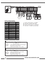
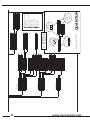
UNWIND WITH MOTOR AND LOAD CELLS
Wiring
+5V
S1+
Com
S1-
DM
Com
TC
Com
AO1
Com
Reg
Init
V+
B
A
V+
+24
Com
CLOSED LOOP
Logic
input B
N.O.
Drive
Output
-10 - +10V
Web
rotation
Load cell
Classic
Tachometer
0 - 10V
R
BK
WH
R
BK
Diam.
Input
0 - 10V
WH
Jumpers
+24 V
AC / DC
Load cell
Classic
Note : all Com / 0V are linked to the ground
Initial set of parameters
File : Force_motor.prm
Process
DISPLAY
Machine / product stopped : B = 0V (OPEN)
Web Tension = HOLD value (Open Loop)
Machine / product running : B = 24V (CLOSED)
Web Tension = SET POINT value (Closed Loop)
Line 1
Line 2
FUNCTIONS Time Delay Start
Time Delay Stop
Hold
INPUTS
Set Point
Diameter Filtering
Tachymeter Filtering
OUTPUTS
Upper Limit
Bottom Limit
Power Gain
REGULATION Max Effort
P
I
D
Measurement Filtering
Open Loop Gain
Closed Loop Gain
Speed Gain
Coeff Speed
Overspeed
Set Point
Measure
1
300
10
100
1000
100
0
10
100
10 (*)
5 (*)
0
100 (*)
0
100
Calcul 1
100
0
1
Regulation Speed Gain = (Dmin x Vl) / Vr
Dmin [m]
Vl [m/min]
Vr [RPM]
Min web diameter
Linear speed for 10V output from tachometer
Max speed of the drive motor
(when set point output =10 V on AO1)
7
+5V
S1+
Wiring
Com
S1-
DM
Com
TC
Com
AO2
Com
Reg
Init
V+
B
A
V+
C2
C1
+24
CLOSED
LOOP
Com
REWIND WITH LOAD CELL + CLUTCH/MOTOR
EMAG
Brake
Logic
input B
N.O.
Drive
Output
-10 - +10V
Web
rotation
Tachometer
0 - 10V
Load cell
Classic
Load cell
Classic
Initial set of parameters
Line 1
Line 2
FUNCTIONS Time Delay Start
Time Delay Stop
Hold
INPUTS
Set Point
Diameter Filtering
Tachymeter Filtering
OUTPUTS
Upper Limit
Bottom Limit
Power Gain
REGULATION Max Effort
P
I
D
Measurement Filtering
Open Loop Gain
Closed Loop Gain
Speed Gain
Coeff Speed
Overspeed
Set Point
Measure
1
300
10
100
1000
100
0
10
100
Process
File : Force_clutch_motor.prm
DISPLAY
Machine / product stopped : B = 0V (OPEN)
Web Tension = HOLD value (Open Loop)
Machine / product running : B = 24V (CLOSED)
Web Tension = SET POINT value (Closed Loop)
100 (*)
20 (*)
0
100 (*)
0
100
Calcul 1
0
Calcul 2
1
Regulation Speed Gain = (Dmin x Vl) / Vr
Dmin [m]
Vl [m/min]
Vr [RPM]
Min web diameter
Linear speed for 10V output from tachometer
Max speed of the drive motor
(when set point output =10 V on AO2)
2
Overspeed = (Ss x AO2max) / Vr
Slipping speed (60 RPM recommended)
Ss [RPM]
Max output from AO2 : 10 V
AO2max [V]
Vr [RPM]
8
R
WH
BK
R
WH
Diam.
Input
0 - 10V
BK
Jumpers
+24 V
AC / DC
Max speed of the drive motor
(when set point output =10 V on AO2)
www.cmccontrols.com
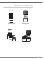
+5V
S1+
S1-
+5V
S1+
Com
BLK
BRN
V
One Load Cell
Full-Bridge
Ultra- Series
Load cell
Classic
Two Load Cells
Half-Bridge
Classic - Series
0
+
Full bridge
Load cell
Ultra
V
-
0
+5V
S1+
BRN
BLK
Com
BLU
WH
BRN
BLK
WH
Load cell
Classic
BLU
R
WH
BK
R
WH
BK
S1-
+5V
S1+
One Load Cell
Half-Bridge
Classic - Series
Com
+
0
Full bridge
Load cell
Ultra
Load cell
Classic
S1-
BLU
-
R
BK
WH
WH
10 kΩ
10 kΩ
S1-
Com
OTHER LOAD CELL CONFIGURATIONS
Wiring
+
V
Full bridge
Load cell
Ultra
Two Load Cells
Full-Bridge
Classic - Series
9
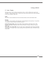
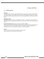
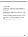
KEYPAD BASICS
1 – SET POINT Setting
2 – Variable Setting
Hold for increase
Ent
• Press both buttons simultaneously
to enter the Data field (visible
underscore)
Hold for decrease
• Press once to increase/decrease
one digit
Escape from
Setting mode
Esc
• Press to validate each digit
• Last digit validation sends the
complete value to the system
(underscore disapears)
4 – System General Settings
Initial readout
Ent
-------------------------------
RECALL MEMORY
Ent
M1
Ent
MEMORY READ
Esc
M2 ... / ... M3 , M4, M5
HOLD
000,0
HOLD
0 0 0 , _0
Variable setting
Esc
WIDTH COEFF
100
WIDTH COEFF
100
Variable setting
Esc
TAPER COEFF
000
TAPER COEFF
000
Variable setting
Esc
Ent
TAPER DIAM.
00,000
Variable
setting
TAPER DIAM.
00,000
MOTOR DIRECTION
- -> + / + -> -
MOTOR DIRECTION
- -> +
Variable setting
Esc
DISPLAY FILTER
000,0
DISPLAY FILTER
000,0
Variable setting
Esc
3 – Additional functions
Releasing Mode
Ent
Press both buttons simultaneously to release the
system (Output = 0)
Esc
Escape from releasing
Hold Mode
10
Ent
Press both buttons simultaneously to block the
system (Output = Max)
This value may be adjusted (see « SET POINT settings »)
Esc
Escape from Hold
www.cmccontrols.com
11
display
inputs
regulation type
functions
outputs
memories
regulation type
open loop
basic PID
variable PID
inputs
measure
set point
diameter
tachymeter
display
language
units
display config.
0
0
0
P (proportional)
I (Integral)
D (derivative)
loop coeff
max Diam. coeff.
min Diam. coeff.
loop coeff.
1
0
max. effort
filtering
7
7
8
7
0.1 9
0.01 9
0 7
0
set point option
filtering
Dmax value
Dmin value
filtering
0
line 1
line 2
calibration
filtering
m
in
measure
diameter
0
0
0
0
0
0
p (proportional)
i (Integral)
d (derivative)
0
100
0.0
0.000
0.0
100.0
0.0
P (proportional)
I (Integral)
D (derivative)
OL coeff.
CL coeff.
inertia gain
speed gain
inertia gain
validate
validate
internal
external 0-10V
upper level val.
bottom level val
AO1 output
AO2 output
set point
diameter
measure
AO1 config
AO2 config
N
kg
lb
Nm
PLI
Ftlb
%
french
english
italiano
deutsch
7
7
7
7
7
7
9
3
3
3
3
coeff speed
overspeed
web width coeff.
web width coeff.
set point value
slope duration
validate
full scale %
validate
0
0.0
100
100
0.0
1
100.0
5
3
3
3
3
12
www.cmccontrols.com
memories
save
call
outputs
thresholds
AO2 readout
logical outputs
power output
functions
time delay start
time delay stop
E-stop option
no-stop
hold
taper
1
duration (* 10ms)
M1
M2
M3
M4
M5
gain
AL1 : error range
AL2 : Diam. limit
set point
measure
diameter
rotation speed
3
3
8
10
1
100
0
13
3
3
10.0 12
0.0 12
0
taper (%)
upper limit
bottom limit
0
hold
enable
disable
fixed
proportional
1
duration (* 10ms)
Set-up using Keypad
Choice in
a list
thresholds
AO2 readout
Menu
Exploration
Ent
Esc
(in less than 2 s)
PASSWORD :
0.01
100
0
0
100
0
0
3
9
11
3
3
3
9
Entering in
data selection
10
11
12
13
Ent
Choice or
parameter
validation
5
3
3
QUANTUM
set point
measure
10.0
0.0
Between 0 and max. effort
1 unit. = 10 ms
000 --> 100
000 --> 100 (valeur entière)
00 --> 10 (V)
0.01 --> 1.00
0000 --> 9999
0001 --> 9999
0.010 --> 99.000
001 --> 999
100 --> 500
-10.0 --> +10.0
001 --> 100
0
0.0
coeff speed
overspeed
1
2
3
4
5
6
7
8
9
100
web width coeff.
upper limit
bottom limit
Esc , Ent , Esc , Ent , Esc
taper diameter
proportional
fixed
OL coeff.
CL coeff.
inertia gain
speed gain
PC SOFTWARE - INSTALLATION AND USE
The CD-Rom delivered with your box contains a PC software dedicated to the QUANTUM, called
QUANTUMsoft.
Launch the “Setup” file to automatically install the software on your PC in:
“C:\ProgramFiles\cmc\quantum\”
During the installation process, a shortcut is automatically created in Run\Programs
The application is launched by a double click on the icon.
To open a pre-set application parameter file, two possibilities are offered:
- click on the thumb index in 'parameter' then 'new' and choose the application type which is
appropriate to you.
- click on 'File' then 'open parameters files…'and under C:\ProgramFiles\merobel\DGT3Soft, open
the file .prm related to your application.
- for direct access to the related help, click the right mouse button.
If you meet problems when installing the QUANTUMsoft on your computer, ensure the
following points:
- the operating system is Windows XP.
- In the event of defect of COM during the launching of the application, make sure that the
cable is properly connected to the COM1 of the PC.
If COM1 is not available, configure the application to work on an alternative port (ex. COM2),
according to following instructions :
. create a shortcut on the desktop for the QUANTUMSoft.exe application.
. click in the properties of the shortcut (right click on the shortcut icon).
. in the thumb index shortcut, write in the target after the access path - com2
(ex. : "C:\Program Files\Program Files\cmc\QUANTUM\quantum.exe" - com2 ).
13
NOTES
14
www.cmccontrols.com
1.0
Parameter
1.1 Communicate parameters to regulator
Save or load a set of parameters on the PC
To save a set of parameters, click in the thumb index 'file' then choose 'save as…' for recording
in a new file (file..PRM.), or 'recording' to record the set of parameters in the file in progress.
To open a set of parameters, click in menu 'file', then choose 'open…'. The set of parameters
will automatically load in the right interface.
The banks of memories of the regulator
There are five internal memories M1 to M5 in the QUANTUM. The memory in progress is
selected by the front panel.
Read the parameters of the regulator
PC software can read these 5 memory banks by clicking on 'read parameter' or in the thumb
index 'regulator' then 'read from regulator' and select the memory.
Send the parameters to the regulator
-To send a set of parameters, you can use the menu 'Regulator,' then 'send to regulator.' Then
select the memory bank in which you want to record the parameters. There is a direct access to
the memories in the icon bar (button 1 to 5).
15
Parameter
1.2 Begin a new parameter setting
Choose the type of parameter setting
Before beginning a new parameter setting, you must select the application type:
Click in menu 'Parameter,' or in the thumb index 'Parameter' then 'New,' choose your application.
-Open loop
Tension control application by measurement of the diameter
Inertia compensation with analogical line speed information
-Closed loop
Tension control application by measurement of the tension or the torque.
Dancer application (control of the dancer roll position)
-Inertia compensation
Tension control application when inertia becomes dominating in the transitional phases.
-Motor command
Use for intermediate tension control or rewinding application with motor speed control
-Speed follower
Use for rewinding application with motorized clutch. The goal is to control the tension
with the clutch and to control the slipping speed in the clutch to undersize it
Each of these application types requires a different set of parameters, choose the category
corresponding to your use of the QUANTUM.
Modify the parameters
The parameters are divided into three or four menus (according to the application type). Click
on the button of one of these menus to modify the contents of it.
Once the parameter setting is finished, you can save it or send to the regulator.
Caution! If you do not save, the set of parameters will be lost when you close the interface.
16
www.cmccontrols.com
2.0
Menu INPUTS
2.1 Measure Menu
This menu appears when choosing closed loop, inertia correction,motor command or speed
follower. It allows calibration for any type of measurement, from a few mV to 10V.
Measure calibration
% full scale: Type in the percentage of full scale corresponding to the upper point used
during calibration (this percentage must be more than 20%).
Valid high level: Type in the value for the upper point.
Valid low level: Type in the value for the lower point.
Procedure:
Fill the 3 parameters and then click on the memory used. Then physically simulate the upper
point and click "valid high level," wait 5 seconds (yellow button), physically simulate the lower
point and click "valid low level," wait 5 seconds (yellow button); calibration is complete.
17
Menu INPUTS
2.2 Set Point Menu
Two types of set points are available
-Internal set point: type in the chosen value, it can be modified by the operator with the
arrows on the keyboard. A ramp can be used for soft start. The ramp is activated when the
switch Regulator is turned on.
-External 0-10V set point: Potentiometer or PLC connected to "set point" pin.
The set point unit is given in menu DISPLAY.
Open loop case:
In this case, the parameter Max Effort must be given. It corresponds to the max product
tension.
This parameter is used to calibrate the system since there is no measure.
Example: CMC Magnetic Particle Brake (EMAG 26)
Nominal torque = 35 Nm at 1 A.
Bobine max diameter = 1 m.
Max current in brake = 0.5 A.
1/ from the EMAG 26 torque vs current, we obtain 0.5A = 22.5Nm.
2/ Max Effort = 22.5Nm / 0.5m = 45N.
Max Effort = 45N (or 4.5kg).
18
www.cmccontrols.com
Menu INPUTS
2.3 Diameter Menu
Diameter calibration
With an analog diameter measure, the signal must be calibrated from physical values (upper point
= max diameter, lower point = min diameter).
Valid max diameter: Type in the max diameter value.
Valid min diameter: Type in the min diameter value.
The diameter unit is chosen in the DISPLAY menu.
Procedure: Fill the values and click on memory used, then physically simulate the max diameter
and click on the button "valid max diameter," wait 5 seconds and do the same with min
diameter and the button "valid min diameter."
19
Menu INPUTS
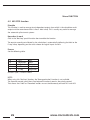
2.2 FILTERING
All the inputs can be filtered. Filtering makes the regulation less sensitive to electric and
mechanical disturbances but generates a delay in the system response time.
A few rules:
Measure :
Filtering depends on the application and product.
Converting force from 100.
Converting force on elastic product from 400.
Dancer from 0.
Set point:
Useful for external set point to filter the signal or simulate a ramp.
Diameter:
It is recommended to use filtering on this signal because diameter is changing
slowly.
The recommended initial value is 100.
Tachymeter: Try to find a compromise between noise reduction and quick response. The
recommended initial value is 10
The QUANTUM uses a first order digital filter, the larger the number you give, the lower the cut
off frequency (Fc) will be and therefore the more filtering you will obtain.
Fc
1
numbers seized 1000
2
500
3
330
4
5
245 195
Fc
18
20
22
25
numbers seize
51
45
40
35
20
29
30
6
7
162 138
8
9
120 106
34
40
50
70
25
20
15
10
10
95
12
78
15
62
110 150
240
5
3
www.cmccontrols.com
1
3.0 Menu DISPLAY
3.1 Units / Display
The front panel is used to display measurement values as well as different data used by the
Controller. These two menus (Units / Display) have to be used to choose what will be displayed
on the two available16 digits lines.
Units
This menu is used to choose the units for the measurement and for the diameter values.
Display
This menu is used to choose what information will be displayed on the two lines. On each line
it is possible to choose between the following options :
Display AO1 (idem AO2): Shows the analogic voltage output on AO1 output (resp. AO2).
Set point / Diameter / Measure: Shows the actual Set point / Diameter / Measure, using the
chosen unit.
Shows AO1 status (idem AO2): Shows the logic inputs configuration viewed by the Controller
(according to A / B digital inputs state), meaning HOLD mode, REGUL mode, RELEASING mode,
Estop mode.
21
4.0 Menu FUNCTION
4.1 E-STOP function
Principle
The E-stop function could be used for the Emergency stop or for any other particular process.
Two different options are available: Fixed E-Stop value and Proportional E-Stop value. The last
one sends an output voltage related to the last current output (before switching to the HOLD
mode)
How does it work
Fixed HOLD value: by entering a value between 0 - 100% , a proportional value between 010V will be sent on the output (i.e. with 50%, 5V will be sent on AO1 output during the HOLD
mode).
Proportional HOLD value: input the gain value (100 - 500%).
The last calculated output value before switching to the HOLD mode will be multiplied by the
chosen gain (i.e. with an actual output value of 3 V (during the normal regulation), the
controller will send 9 V to the ouptut if the gain has been set to 300%.
Process
The E-stop mode is managed by the following digital inputs:
external switch A closed - external switch B closed
22
www.cmccontrols.com
Menu FUNCTION
4.2 Time Delay Menu
Principle
When the machine process management (motor start and stop) is not synchronized with the
controller logical inputs remote control (external switches Reg and B), some regulation troubles
can appear. The synchronizing problems can be solved with the time delay options available in
the Controller functions.
How it works
Starting time delay: Entering a time delay value (tens of milliseconds), means that the system
will wait for that delay before the controller starts the actual calculation (after switching Reg
from open to closed position).
Stopping time delay: Entering a time delay value (tens of milliseconds), means that the
system will wait for that delay before the controller stops the actual calculation (after switching
Reg from closed to open position).
The same effect will be applied on the delay to switch from Regulation mode to Hold mode
Process
It is usually necessary to manage the switches Reg and B simultaneously.
23
Menu FUNCTION
4.3 HOLD function
Principle
The Hold function can be used by the operator for the machine settings (out of regulation
mode). It allows the operator to directly manage a constant ouptut voltage level (parameter
always available on the controller front panel).
How does it work
Hold value: Entering 0-100% means 0-10V proportional output voltage
Process
Two different ways are available to manage this function:
External switch A open - external switch B open by the front panel operator menu (priority
access)
24
www.cmccontrols.com
Menu FUNCTION
4.4 Inertia
This menu is available for open loop configuration when inertia compensation is required.
Inertia compensation function
The inertia compensation function allows the controller to increase or decrease the output
during the acceleration/deceleration periods. This coefficient (inertia gain) is related to the roll
inertia (proportional to the actual diameter measurement) and to the actual line speed
(tachometer input). When the web width is not constant, it is possible to adjust the calculated
inertia term by entering the coefficient Web width (also always available to the operator on the
controller front panel).
Calculation - Inertia gain GI:
Data:
Max roll weight M (Kg)
Max roll diameter D (m)
Max line speed VL (m/s)
Decceleration duration T (s)
Rated current for the chosen Brake IC (A)
Max current adjusted on the power supply board IR (A)
Rated torque for the chosen Brake CN (Nm)
Formula :
GI = M x VL x D x IC x 100
240 x T x CN x IR
Adjustment procedure:
Proceed with the first tests with the maximum web width (Coeff. Web width = 100 %).
Temporarily disable the open loop control (Closed loop gain = 0 %) to avoid interactions during
the adjustment procedure.
-
Apply a high filtering coefficient on the diameter input (slow variation input): Diameter
filtering = 500
Enter a low filtering coefficient on the Tachy measurement input to avoid fast transient
troubles
Apply the calculated inertia gain (above formula)
Start the machine and adjust the inertia gain value to stabilize the actual measurement
during acceleration/deceleration periods.
25
Menu FUNCTION
4.5 NO-STOP function
Principle
This function is used to manage two independent outputs (one which is the calculation result
output and the second one which is fixed - hold value). This is usually very useful to manage
the automatic splice turrets systems.
How does it work
Click in the "No-Stop" special function box to enable the function.
The ouptut currently not affected by the calculation is automatically delivering the Hold or the
E-stop value, depending on the status chosen for logical inputs A and B.
Process
See the following table:
AB
00
01
10
11
AO1
Regulation
Regulation
Hold
E-Stop
AO2
Hold
E-Stop
Regulation
Regulation
0 means Open / 1 means Closed
NOTE:
When using this "No-Stop" function, the "Demagnetization" function is not available.
The Operator control panel (front face keyboard functions) remains the priority control.
That means that "Hold" or "Freewheel" modes are sent simultaneously on both AO1 and AO2.
26
www.cmccontrols.com
5.0 Menu PID
5.1 Coefficients Menu
This menu is available for both closed loop and inertia compensation configurations.
5.2 Closed loop + Open loop Control function
When using a closed loop configuration, this function allows integration with an open loop control by using
a specific coefficient for each of these control modes; open loop gain and closed loop gain. This function
allows additional closed loop control around the result of an open loop control, in order to limit the Measure
- Set point difference, to improve the system stability as well as the accuracy.
Calculation - Open loop gain CBO
DATA :
Max Force range F (N)
Max web diameter D (m)
Rated current for the chosen Brake IC (A)
Max current adjusted on the power supply board IR (A)
Rated torque for the chosen Brake CN (Nm)
Formula:
CBO = F x D x IC x 100
2 x CN x IR
The result gives the open loop true coefficient. This value can be modified to optimize the system stability.
5.3 Inertia compensation function
The Inertia compensation function allows an additional open loop control to the calculated currrent closed
loop result during the acceleration/deceleration periods. This coefficient (inertia gain) is related to the roll
inertia (proportional to the actual diameter measurement) and to the actual line speed (tachometer input).
When the Web width is not constant, it is possible to adjust the calculated inertia term by entering the
coefficient Web width (also available to the operator on the controller front panel).
Calculation - Inertia gain GI:
Data:
Max roll weight M ( Kg )
Max roll diameter D ( m )
Max line speed VL ( m/s )
Decceleration duration T ( s )
Rated current for the chosen Brake IC ( A )
Max current adjusted on the power supply board IR ( A )
Rated torque for the chosen Brake CN ( N.m )
Formula:
GI = M x VL x D x IC x 100
240 x T x CN x IR
Adjustment procedure:
Proceed with the first tests with the maximum Web width (Coeff. Web width = 100%). Temporarily
disable the open loop control (Closed loop gain = 0 %) to avoid interactions during the adjustment
procedure. Apply a high filtering coefficient on the diameter input (slow variation input): Diameter
filtering = 500. Enter a low filtering coefficient on the Tachy measurement input to avoid fast transient
troubles. Apply the calculated Inertia gain (above formula). Start the machine and adjust the inertia
gain value to stabilize the actual measurement during acceleration/deceleration periods.
27
5.0 Menu PID
5.4 PID Menu
Principle
The P.I.D. is the heart of the controller calculation system when using the Closed loop mode.
P , I , and D parameters are the coefficients which give the actual output result from the
Measurement - Set point difference .
CAUTION : the PID calculation must be disabled during the machine rest periods to avoid that
a static Measurement - Set point difference increases the output value to the maximum (giving
a very high overshoot for the next machine restart) .
The following process has obviously to be managed by the global machine management system
! (using the external switches Reg and Init) .
How does it work
There are two options for the PID calculation principle :Fixed PID (coefficients) or Variable PID
(coefficients) which have to be chosen in the PID Menu (" click in the box " choice mode) .
The Variable PID option is very useful when the Fixed PID is unable to keep the same stability
level for the whole range of the Web diameter variation .
The Variable PID option offers to define a P, I and D specific value for the min. diameter, and a
different one for the max. diameter . the three P, I, and D parameters will be automatically
updated in relation to a diameter measurement input (linear variation between min. and max.
for each parameter)
P parameter: This parameter is the direct gain on the Measurement - Set point difference .
The P coefficient will directly affect the global system response time .
CAUTION : The higher the value, the higher the response time, but with a lower stability .
I parameter: This parameter is used to cancel the " static error " by the accumulation of this
error from the beginning, and by adding this error to the set point until reaching the equality .
When the Measurement - Set point difference becomes null, the Integral value is stabilized.
A high coefficient value will make the system more reactif by decreasing the time for the
Measure to reach the Set point actual value .
D parameter: This parameter is used to help the system to react for fast transients.
It is generally only used for the Dancer applications, in order to stabilize the dancer position
when the web speed is variable .
CAUTION : this parameter is used for react to transients, but it means that it could be highly
sensitive to the electric interferences on the measurement signal .Be very careful to connect the
wiring shields at the best .
Process
The PID calculation is managed by the external switches Reg and Init.
Init
Reg
PID calcul mode
0
0
Stopped (blocked)
1
0
initialisation
0
1
processing
1
1
processing
CAUTION : when using the diameter calculation (counters inputs), the initialisation of diameter
calculation is managed by the same external switches (Reg = 0 , Init = 1)
28
www.cmccontrols.com
5.0 Menu PID
5.5 Motor
This menu is available in motor command configuration.
Tension control for motorized rewinder in speed regulation.
In this case, we need linear speed (tacho) and diameter information to calculate the rotation
speed of the motor.
Motor gain is then the coefficient linking the different parameters:
Motor gain calculation:
Parameters : 10v on diameter input = D ( m )
10v on tacho input = Vl (m/min)
10v on output AO1 = speed set point for the drive = Vr (rpm)
Calculation : Motor gain = Pi x D x Vr
Vl
With this rotation speed calculation, we have an open loop system on the speed control.
To control the tension on the product, the DGT regulates the open loop calculation with a
closed loop (PID adjustement) on tension measurement.
For this application, Coefficient motor = 100%
Note : In this configuration, Overspeed = 0.
Special case: Tension control through clutch and speed follower on rewinder
This model is done to solve dissipation problem in clutch on the rewinding side.
The goal is to drive tension on the product with the clutch and drive the motor speed to keep
low slipping in the clutch.
AO1 input : dedicated to clutch control (PID regulation with tension control).
AO2 input :dedicated to motor speed control. The DGT calculates the rotation speed with linear
speed and diameter information. Motor gain is calculated like here above.
To ensure a minimum slipping for the right working of the clutch, it is necessary to add an
overspeed constant (usually equivalent to 60rpm).
Overspeed calculation:
Parameter : 10v on AO2 output = speed set point for the drive = Vr (rpm)
(de 0.0Và 10.0V)
Calculation : overspeed = 60(rpm) * 10(V)
Vr (rpm)
For this application, Coefficient motor = 0% (generate automatically AO2 as speed output).
Important note: If motor gain =0, motor configuration is not validated and settings are
memorized as closed loop configuration.
29
6.0 Menu OUTPUTS
6.1 Working range
Principle
This function defines the two limits for the actual regulation voltage output AO1 (or AO1 and
AO2 when using the No-Stop mode) inside the global output range (-10 / + 10 V). Useful
function when using the controller with a device which only uses 0 - +10V input.
How does it work
Min. threshold: Means the minimum voltage allowed to the controller regulated output
(enter the threshold value between -10V et +10V).
Max. threshold: Means the maximum voltage allowed to the controller regulated output
(enter the threshold value between -10V et +10V - must be higher than the Min. threshold
already defined).
30
www.cmccontrols.com
Menu OUTPUTS
6.2 DISPLAY output function (AO2)
This function is used to select one of the following four items to be displayed:
-Set point (0 to 10V = whole measurement range as it has already been calibrated)
-Measure (-10V to +10V = whole measurement range as it has already been calibrated)
-Diameter (0 to 10V = 0 to the Max diameter)
-Linear speed for the speed follower menu
31
Menu OUTPUTS
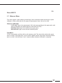
6.3 Current limitation
Principle
This function limits the current in the coil when using EMAG brakes and EMAG clutches directly.
As the supply of the coil is done by a pulse width modulation on the rectified supply of the
QUANTUM, the parameter drives the duty cycle of the PWM.
How does it work
Enter a value between 1-100% corresponding to the maximum current for the application.
Example
Case of an EMAG 50 (65Nm - 1A nominal current-200hm impedance) used for a 50Nm
maximum torque application (equivalent to 0.7A).
1. QUANTUM supply with a 24Vac transformer.
The supply of the coil is done on the 24V rectified meaning around 34Vdc.
The impedance is 20Ohm, so the max available current is 1.7A.
To limit the current at 0.7A, the duty cycle is 41%.
2. QUANTUM supply with a 24Vdc converter.
The supply of the coil is done on the 24Vdc
The impedance is 20Ohm, so the max available current is 1.2A.
To limit the current at 0.7A, the duty cycle is 58%.
This parameter is useful for dancer applications by limiting the current at the lowest value
needed to pull the dancer for the max roll with the max tension.
32
www.cmccontrols.com
Menu OUTPUTS
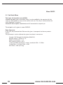
6.4 ALARM management function
Principle
Two digital outputs have been designed to provide two different alarm signals:
Regulation fault: When the Measurement - Set point difference is over the pre-set tolerance, it
means that there is something wrong in the process.
Min. Diameter: Diameter measurement threshold available to alert the operator before the real end
of the bobbin.
How does it work
Error range parameter: The digital output AL1 will be closed for an actual Measurement - Set
point difference higher than the chosen percentage.
Diam Threshold parameter: The digital output AL2 will be closed for an actual Diameter
measurement below the chosen percentage of full scale diameter.
Example
Error range:
For a 5 kg set point and 10 % Error range, the AL1 output will be closed for a measurement out of
the 4.5 to 5.5 kg range ( +/- 10 % of the current set point)
Diam Threshold :
Diameter range = 0.2 to 1.0 m
Actual working range = 1.0 - 0.2 = 0.8 m
For 5 % Diam threshold, the AL2 output will be closed as soon as the actual diameter is lower
than 0.24 m
Alarm diameter = core diameter + (Actual working range x Diameter threshold) 0.2 + (0.8 x 5%)
= 0.24m
Process
AL1 and / or AL2 digital outputs remain closed until the time that the related measurements are
out of the correct range.
CAUTION: AL1 and AL2 are driven by optocoupling components. The common (0 V) point for both
is ALMax output capability: Vceo = 300 V
33
7.0 Digital Inputs
7.1 Digital Inputs A and B
Principle
The digital inputs A and B are dedicated to the management of the controller’s global status. It
provides the user the ability to create an automatic relationship between the machine process
and the controller status (i.e. to manage the E-Stop needs).
How does it work
The following table shows the controller’s main status for any different combination of A and B
switch positions, as long as the No-Stop mode is not activated (see SPECIAL FUNCTIONS Menu /
No-Stop Function).
A
0
0
1
1
B
0
1
0
1
Output AO1
Hold
Regul
Release
E-Stop
0 means: Switch Open / 1 means: switch closed (to the 24Vdc terminal)
The operator control panel (front face keyboard functions) remains the priority control.
34
www.cmccontrols.com
Digital Inputs
7.2 Logical inputs Reg and Init
Principle
The digital inputs Reg and Init are dedicated to the management of the P.I.D. calculation
process.
How does it work
The following table shows the calculation process status for any different combination of Reg
and Init switches positions:
Init
0
1
0
1
Reg
0
0
1
1
PID calculation
calculation stopped
calculation initialization
calculation in process
calculation in process
0 means: Switch Open / 1 means: switch closed (to the 24Vdc terminal)
35
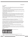
8.0 Data Capture
8.1 DATA CAPTURE Menu
Starting a Data Capture
The PC software includes a Data capture function, allowing to visualize and to record each
Controller input/output actual value/status, four times/sec. To start a data capture, go to the
REGULATOR / Start Acquisition option.
To record the data on the computer, enter a new File name (ext., .acq). The data capture will
start and the data will be saved in the related file. To look at the data without recording,
choose ‘Cancel.’ The data capture will be started without recording. In both cases, press ‘Stop’
to end the data capture process.
Using the recording option during the data capture allows you to store the data on the disk as
a data file (ext., .acq). The data is displayed as a text file (columns separator = Tab) which can
be read by any spreadsheet software.
NOTE: The data is collected 4 times / sec, meaning the time base between two lines is 250 ms
(1/4s) .
How to display the acquired file
To display the curves of the acquired file, click on the menu 'acquisition' then select 'visualize' or
click directely in the icon bar. A new window opens and you have to load the acquired file.
Select the curves you want to see. A multi-curves option can be selected when clicking in
'customize'.
36
www.cmccontrols.com
7550 HUB PARKWAY
CLEVELAND, OH 44125
216.524.8800 or 800.321.8072
www.cmccontrols.com
MAN-70421