1
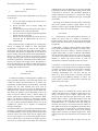
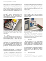
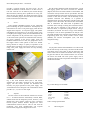
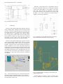
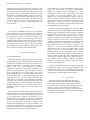
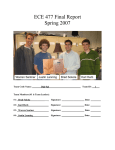
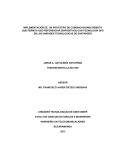
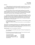
Senior Design Project 2013 – ClockAide
1
ClockAide
Joel Jean-Claude, Sachin Honnudike, Anita Ganesan, Eric Moore
Abstract — ClockAide is an interactive educational
system devised to help a specific group of students with
special needs from West Springfield Middle
School learn how to read and set time. In addition, the
device provides the students with a quiet environment to
practice entering their lunch identification numbers.
The design stemmed from a presentation given by their
teacher, Megan Ferrari, at the University of
Massachusetts
Amherst.
She
often
encounters obstacles when trying to teach her students
how to tell time and proposed our team to take lead on
finding an innovative solution to assist her. The students
learn how to tell time using our three - mode system
which prompts them with questions of varying
difficulty. Our electronic device will be simple, and user
friendly and will ultimately allow students of all levels
learn how to read and set any analog clock.
In addition to this, Ms. Ferrari proposed other
situations that her students found hindering. One place
was in the lunchroom. These students must get lunch ten
to fifteen minutes early so that they can focus on
punching in their lunch ID numbers and get their
lunches without feeling overwhelmed by the other
students in the school. We believed we could also help
the students with this issue as well and implemented it
within ClockAide. With our detachable keypad, we can
assist students with entering ID numbers by including a
login system. By extension, our group is able to extend
this functionality through the use of a tracking system.
It records activity data like session length, response in
the quiz modes, the student lunch numbers, etc. The
data can be accessed externally as an Excel spreadsheet,
which makes it possible for Ms. Ferrari to see how
students are using the device, their progress, program
lunch IDs for new students.
social studies teacher at West Springfield Middle School
says that, “If kids want to know the time, they pull out their
cell phones” [25]. In addition, teachers now see that young
students have no idea how to read an analog clock since
they are mostly exposed to digital clocks at home.1 Right
now, there are websites and some types of toys dedicated to
helping children read or know the general hour it is during
the day. Along with this, there are two types of educational
toys that have been on the market similar to the one that we
are producing. The first is named the “Onearoo” dual clock
and nightlight which only tells time by the hour for children
but continues their dependence on adults to tell them the
correct time. Another device similar to our design is the
“Momo Clock” which is a sleep trainer for young children.
This clock tries to implement a regular sleep cycle for small
children by showing an image of a sleeping monkey at
night to teach the child that they should be sleeping if the
eyes are closed.2 Created around 2008, these are the most
recent devices produced and the most popular so far.3
Megan Ferrari, the teacher we are working with in West
Springfield, informed us that she teaches the students with
cardboard clocks but are seeing that they have difficulty
with telling times due to the angle of the hands. In addition
to this, she also told us that the position of the minute and
hour hands of the clock confuse the children and
continuously ask her for assistance when staring at the
clock. Our end goal is to allow the students to gain
confidence and independence while they use our device and
create a sense of accomplishment when they start reading
the time off an analog clock. The integration with
intelligent quiz logic within our device sets our product
apart from anything else on the market. When it comes to
the clock portion of our device, the social impacts of our
device could be considerable. While the lunch ID portion is
to specifically help the students of West Springfield, our
product could also help students around the country learn
this necessary skill.
I. INTRODUCTION
ClockAide is an educational device in which we use a
keypad and a three-mode user interface to solve a specific
problem in a class of students with special needs at West
Springfield Middle School. However, it can also be applied
to students all around the nation who need help reading and
setting time. This presents a significant problem as every
child needs to learn how to read and set an analog clock, but
many have trouble with this concept. Colleen Steele, a
1
"Massachusetts." The Republican. N.p., n.d. Web. 02 Dec. 2012.
<http://www.masslive.com/news/index.ssf/2009/12/teachers_say_children
_are_beco.html>.
2
"Sleeptrainer Clock - Momo Monkey." - UrbanBaby. N.p., n.d.
Web. 02 Dec. 2012. <http://www.urbanbaby.com.au/Sleeptrainer-ClockMomo-Monkey>.
3
"American Innovative." - Company History. N.p., n.d. Web. 02
Dec. 2012. <http://www.americaninnovative.com/about/>.
Senior Design Project 2013 – ClockAide
II. REQUIREMENTS
A.
Requirements List
The following is a list if the requirements set by the group
on this project:
1.
2.
3.
4.
5.
Device will speak and display the current time to
user when prompted.
Device will allow user to practice reading and
setting time.
Device will allow users lacking fine motor skills to
turn knobs for easy setting of the hands.
Device will take user input through the keypad and
display the time on the clock.
Device size will not obstruct the normal use of the
classroom and be approximately the size of a
students' desk.
Each requirement plays an important role in ClockAide's
success in helping the students of West Springfield.
Requirement 1 emphasizes the need for the student to
always know the current time rather than constantly asking
their teacher. Requirement 2 emphasizes the user ability to
practice reading and setting arbitrary times. Requirement 3
allows every student to be able to use the device without
struggle especially when testing their skills during Read and
Set modes. Requirement 4 demonstrates the communication
between the keypad and stepper motor. Requirement 5
shows the importance of an unobtrusive design with respect
to the other individuals that interact within the classroom
including other students and staff.
III. DESIGN
A.
System Overview
To address the challenge of teaching time to children, our
group proposed ClockAide, a device that will interact with
a child in a similar way that teachers do. It features two
main modes, Normal and Quiz. In normal mode, ClockAide
operates like any other standard wall clock, with an
additional feature. Any user can press the appropriate key
during this mode, and the current time will be spoken out.
This allows the children in West Springfield to have the
ability to find out what the time is, without asking the
teacher. Quiz mode is composed of two sub-modes: Read,
and Set. All modes of operation are described in further
detail in the next section. This project is primarily tailored
to a class at West Springfield Middle School, but can be
expanded for general use to students in kindergarten
through second grade.
To build ClockAide, our group employed embedded system
technology to implement the features defined above. Using
the Arduino platform, our group designed two modules that
would be used in the system. First was the stepper motor
circuit, whose purpose is to run the analog display the user
sees to read the time. The second is the keypad, which is
used to log in, switch modes, and interact with ClockAide
2
in Read Mode. Using the Raspberry Pi, our group extended
keypad functionality to include a data logging system which
is described in section H. This provided a platform to
combine hardware and software to construct the analog
display, speech prompts, intelligent quiz logic, and keypad
functionality.
Our design can be broken down into primary components
such as the interface, activation, stepper motors, etc. The
following sections will go through the details of our design
by breaking it down into each component.
B. Activation
1)
Normal Mode - This modes' primary function is to
display the current time. If a student is interested in
knowing what the time is, they can press the Normal mode
button on the front of the device, and ClockAide will output
an audio file.
2) Read Mode - Tests the cognitive abilities of the student.
In this mode, the Raspberry Pi chooses an arbitrary time,
and prompts the user to submit a response through the
keypad. If the answer is correct, ClockAide acknowledges
this, and gives the user the choice to try again. If the answer
is incorrect, ClockAide will give the user two additional
attempts to achieve the correct answer. If both are
unsuccessful, ClockAide will speak out the correct time.
3) Set Mode - In this mode, the device chooses an arbitrary
time displayed on the keypad and thus prompts the student
to submit a response by moving the two knobs controlling
the hour and minute hands. If the answer is correct,
ClockAide acknowledges this, and gives the user the
choice to try again. If the answer is incorrect, ClockAide
will give the user two additional attempts to achieve the
correct answer. If both are unsuccessful, ClockAide will
speak out the correct time.
A. Stepper Motor and Knobs
Stepper motors are brushless DC electric motors that
divide a full rotation into a number of equal steps. In our
design, we make use of two unipolar stepper motors (one
driving the hour hand and the other driving the minute
hand) in order to achieve a good representation of time and
also to enable us control the arms of the clock using two
independent knobs. In a traditional clock, both hands are
moved by one motor but we found it easier for students to
learn when the hands move independently from each other.
This design choice was made bearing in mind the relatively
simpler complexity of the driver circuit of the unipolar
stepper motor versus that of a bipolar stepper motor. Both
of these motors have full rotations that are divided into 200
steps.
In order to translate the number of steps moved by the
Senior Design Project 2013 – ClockAide
motor to a time, a C++ library was written along with its
corresponding header file. This library primarily contained
logic to drive the motor and to move the motor by a specific
number of steps. In Normal mode, both motors move
sequentially to provide a correct display of time. In Read
mode, the position of the motors is set by the Raspberry Pi
to enable the student read the time and in Set mode the
motors are controlled by knobs, used by the student to set
the time.
The stepper motors use optical sensors to mark a
reference point for rotation. This reference point is set to 12
(noon). This is required for the proper operation of Set
mode. These motors can rotate either clockwise or
counterclockwise. It is preferred, however, that the students
set the time in the clockwise direction.
Fig. 1 The two unipolar stepper motors and the driveshaft
system that allows the hour and minute hands to move
independently.
B.
Keypad
The keypad is primarily used to allow the student to
practice entering their lunch identification numbers without
getting overwhelmed. When a student starts with
ClockAide, he or she must enter their identification number
to log in. This gives them a chance to practice entering their
ID in a quieter setting. In addition, the keypad also acts as a
second input for the student to choose a specific mode. By
entering either a 1, 2 or 3 (Normal Mode, Set Mode or Read
Mode, respectively) the student enters that specific mode.
In Normal mode, the student can press any number on the
keypad to hear the current time. During Set mode, this
procedure will be used to enter responses. After the student
has been prompted to set the clock to a specific time, they
will use the knobs located on the face of the device to move
the hands of the clock to the proper time. For Read mode,
ClockAide will move the hands to an arbitrary time
prompting the student to dial their response on the keypad.
To make the keypad operational, it had to be reverse
engineered. This part was purchased from a private vendor,
so it did not include proper documentation, or power cables
to operate it. Upon detailed inspection, the keypad consisted
of three main parts: a button matrix, an LCD screen, and a
3
microcontroller working as an interface for the buttons to
the display. For our purposes, the button matrix was
repurposed to work with the Arduino Pro microcontroller.
We noticed that the matrix mapping of our keypad was
much different than that used by the lunch room at the
middle school and therefore, we had to re-engineer it which
took a bit of time.
This particular keypad was chosen because it was the
only one the group found that closely resembled the one at
the lunch room at West Springfield Middle School. The
buttons are soft to the touch, and are clearly labeled. Our
group was not able to obtain an exact model because the
extras were discarded and would require us to pay around
300 dollars to replace.
Fig. 2 The keypad and LCD setup with the Arduino Pro
shown above the casing.
The Arduino Pro is a much smaller version of the
traditional Arduino prototype board. The Arduino Pro
features the same pin layout and Atmega processor. The
keypad matrix and LCD screen will be soldered onto the
Arduino Pro and integrated into the case.
C.
Audio System
Ms. Ferrari recorded all of the hours, minutes (5-minute
intervals), and wildcards (e.g: o’clock and noon) in a single
audio file. Megan’s voice was used so that the audio output
will be natural and similar to what the students would hear
when they practice in class with Ms. Ferrari. The opensource audio editor Audacity was used to process the audio
file and remove background noise. The file was amplified
prior to being broken into separate MP3 encoded files for
each hour and minute. These MP3 files were placed on a
micro SD card into separate folders (e.g: hours, minutes,
wildcard).
D.
Additional Functionality
1) Identification Feedback
This is the mode that is primarily driven by the keypad.
The child will enter his or her ID number, and the system
Senior Design Project 2013 – ClockAide
provides a response through the LCD screen. All the
student ID numbers would be stored in an SD card as a
CSV file. This file can be edited by the teacher through
Microsoft Excel, allowing her to update the list every year
when she gets new students. This allows the teacher to keep
track of a students progress and also allows Set and Read
modes to function more efficiently.
E.
Power
Using multiple embedded systems for the ClockAide
posed a challenge for power distribution. The Raspberry Pi
and Arduino Uno need a 5 volt power supply, while the two
stepper motors require a 15 volt power supply. The speaker
and amplifier are powered by a 12 volt power supply. Using
a computer power supply (ATX), and a breakout board, the
various components can be powered from a single source.
A 9W load resistor provides the minimum load necessary
for proper operation of the power supply. Since the
breakout board maxed out at 12V, the group had to see if
the stepper motors could operate at that level. Further
testing showed no change in quality of operation of the
stepper motors. The motor circuit can be driven at 12 volts.
Using a PC power supply also allows for easy mounting
into the case.
Fig. 3 The ATX breakout board (with a 9W resistor
soldered onto the board) connected to the ATX power
supply. The 9W resistor provides the minimum load
necessary for proper operation of the power supply. The
ATX breakout board is designed. The ATX breakout board
provides 12, 5, 3.3, and -12 volts output.
F.
Software
The first version of the ClockAide software was written
in C++. It featured the basic functionality: Normal, Read,
and Set modes. For the integration process, however, it was
decided that using Python would be more convenient
because Python contains libraries designed for serial
communication between devices. This fit well with the
ClockAide, since serial communication was required
between the Pi, keypad, and stepper motor circuit.
4
For the teacher feedback system described above, a local
data logging system was used. It consists of a database
(SQLite) that stores the lunch numbers of the students, and
records the activity between the two quiz modes. The data
recorded includes the session start and stop times, responses
entered in read and set modes, and the difficulty of the
questions answered. The difficulty of a question is
determined from previous discussions with Ms. Ferrari and
multiple visits to the school. We observed how the students
take in information and what kinds of problems they
encounter when working on telling time with their teacher.
This data can be exported to CSV format for use in
Microsoft Excel, as requested by Megan Ferrari. Using a
USB drive, the teacher can extract a copy of the database,
and import it into an Excel spreadsheet for analysis. This
was made possible using concepts from Software Intensive
Engineering (ECE 373), which include version control
(GitHub), the iterative development cycle, and basic
integration testing.
G.
Casing
Acrylic plastic ordered from McMaster-Carr will be used
for the sides and top of the casing. The front and back sides
will feature clear acrylic glass so that the electronics and
motors inside can be viewed. The bottom of the casing will
be plywood. Shelves will created inside the case to house
the motors and PCB. The ATX power supply will be
mounted to the plywood. The speakers and amplifier will be
mounted on the sides.
Fig. 5 Outer Design of ClockAide
Specification
Value
Weight
Height
Length
Width
Power Supply
Keypad
5 lbs
12 inches
18 inches
12 inches
12V DC
Detachable
Table 1 Design Specifications
H.
Block Diagram
Senior Design Project 2013 – ClockAide
5
After this is done, the user has to organize the routes to
his or her preferences. After that, it is suggested to perform
a design rules check (DRC), to see if there are any major
errors that could prevent the fabrication from being
successful. If there errors are found, they are corrected, and
the DRC is run again. Otherwise, the PCB design is
complete, and ready for fabrication.
Fig. 6 Overall system overview.
I.
PCB Design
There are many popular PCB design programs out there
today, including Eagle, and PCB Artist. The component that
was most in need of a dedicated printed circuit board was
the stepper motor circuit. It consists of two stepper motors,
two optical sensors, a Darlington array, and an Arduino
Uno. A design was created to reduce the size of the circuit,
and to provide a simple way to tap power from a breakout
board that is used to power the Pi, and the keypad. We
found that it may also need to be connected to the RTC.
Fig. 8. Schematic. Used to make sure all the connections
were present before performing route processing
There are many popular PCB design programs out there
today, including Eagle, PCB and Artist. The one our group
went with was Fritzing, from an open source community in
Germany. The reason why we chose Fritzing was because it
made it possible for use to create a layout the diagram of
the physical circuit on the program, and the software would
automatically generate the schematic diagram, and the PCB.
This made the drafting process straightforward. Once the
circuit was laid out in Fritzing, the schematic was adjusted
accordingly to verify that all the necessary connections
were present.
Fig. 7. Once the connections were verified, the routes were
performed using the AutoRoute feature. This is a process
where the software creates the electrical connections for all
the components of the circuit.
Fig. 9. Completed design, with proper routes, labels, and
component placement.
Another feature of Fritzing is that it provides direct
access to fabrication services through the user interface.
Senior Design Project 2013 – ClockAide
Through the click of a button, the user can prepare an order
directly from the Fritzing website, and get it back in two
weeks. The drawback to this was the turnaround time, since
the board was going to be fabricated in Europe. Since Joel
had experience with PCB assembly in the past, he used his
contacts to see if he could find a fabricator in the U.S. that
could deliver a fabricated PCB faster. He found Advanced
Circuits, in Oregon, that not only beat Fritzing's price, but
was also within U.S. borders, which helps shorten the
turnaround time.
6
To accomplish all our goals, Sachin and Eric had the task of
writing the system code to establish communication
between the stepper motor and Raspberry Pi. Eric
developed the libraries for the stepper motor and worked
with Sachin in coding these libraries with a view to
implement our unique functionalities. Extensive work was
done in calculating various parameters related to how the
stepper motors would drive the hands to achieve an accurate
representation of time. This code was responsible for the
functionality of the Normal and Set modes and well as the
audio feedback portion of ClockAide.
IV. POWER SUPPLY
Using multiple embedded systems for the ClockAide
posed a challenge for power consumption. The Raspberry
Pi and Arduino Uno need a 5 volt power supply, while the
two stepper motors require a 12 volt power supply. Using
an ATX power supply, and a breakout board, the various
components can be powered from a single source. Since the
breakout board maxed out at 12V, the group had to see if
the stepper motors could operate at that level. Further
testing showed no change in quality of operation, so it was
okay to use the 12V setting on the breakout board.
V. PROJECT MANAGEMENT
A. Team Member Roles
Each of the members of our group has a set of skills and
strengths that they can contribute their knowledge and also
expand their knowledge as well. First off, we made a list of
tasks that would allow us to complete our project on time –
drawing block and circuit diagrams of different
components, writing drivers for specific components, core
system code and algorithms, the user interface, hardware
device integration, power system design and overall
physical implementation – each with divisible sub tasks. As
we went through this list, each team member gave their
initial idea for how to go about that task and with their
initial interest, we were able to start delegating assignments
accordingly. We set tasks within the Gantt charts along with
corresponding dates of expected completion. By looking at
the Fall and Spring Gantt charts we created, we were able to
look and see what we needed to have done in time for our
deliverables.
The deliverables were first discussed amongst the group
members and then were established and agreed upon by the
review board and our advisor. ClockAide is primary based
on the communication between the Raspberry Pi, the
stepper motors and the keypad. The position of the minute
hand and hour hand depend on the input from the knobs as
well as our stepper motor algorithm. In addition, other
modes require the Raspberry Pi to output an arbitrary time
to either the stepper motors or the keypad. This requires
both low level software for the Raspberry pi and devices,
and high level software for the positional analysis.
Additional functionality including the quiz logic, Read
mode and accessing the system through lunch identification
numbers were accomplished by Joel and Anita. Finding a
keypad suitable for the students to use was one of the big
obstacles of this project, and required Anita to reverse
engineer the keypad twice throughout the duration of the
project. In addition, she also took on the responsibility to
complete the design and construction of ClockAide. Joel
developed the logic for Normal, Read, and Set modes, so
that ClockAide interacts with the user. Initially, it was
written in C++, but was later translated to Python to make
integration with the keypad and stepper motor system
easier. At that point, Joel and Sachin worked on the
feedback tracking system, using SQLite, also in Python.
Joel worked on storing lunch numbers, session length, and
the user responses in the quiz modes, while Sachin worked
on building the Question Bank that contains ratings for
easy, medium, and hard questions. Both Joel and Sachin
worked on automating the process to export the data to
Excel and other related work.
Each of the team members worked equally on software
and hardware sections on each of the components. We
debugged each other’s code and eventually had functional
software for the stepper motor, audio feedback and keypad
components for each subsystem of the ClockAide.
VI. CONCLUSION
ClockAide provides a fun, educational device for
students with special needs in West Springfield Middle
School but will also be used to teach people of all levels
how to read and set an analog clock. In closing, out project
has been a success. We have been able to meet all our
original requirements thus far. In reality, we are giving the
students the increased independence that their teacher asked
us to supply with ClockAide.
Senior Design Project 2013 – ClockAide
VII.
ACKNOWLEDGEMENTS
Megan Ferrari – Teacher at West Springfield Middle
School
She is the direct beneficiary of this project. She reached
out to the group at the beginning of the semester and
explained what her needs were. Our group chose to work
with her. She also invited us to see the children and get
feedback on the device.
Team ClockAide faculty advisor 2012– Professor T.B.
Soules
Professor Soules met with our group weekly to discuss
ideas, future plans and continuously helped us overcome
hindrances in our design. We bounced different concepts
with him and took his advice very seriously due to his
extensive background and knowledge in Electrical and
Computer Engineering.
Team ClockAide faculty advisor 2013– Profesor
William Leonard
Professor Leonard took over as our adviser later on in the
year. He provided very useful feedback and checked in with
our group weekly to monitor our progress.
Instructors / Course Coordinators – Professor
Christopher Hollot and Professor Christopher Salthouse
These two professors gave us great insight and advice
during one-on-one meetings with our group in lab, email
correspondence and classroom lectures about different
design principles, working productively in a group and
prototyping to meet specifications.
Senior Design Project Evaluators - Professor
Janaswamy and Professor Ciesielski
These two professors took time out of their busy
schedules to watch and evaluate our progress during each
stage of our design. Throughout the process, provided
useful feedback during our Preliminary Design Review
(PDR) presentation that helped us reshape and re-evaluate
different components of our project. Specifically, they
informed us on what they expect for the Midyear Design
Review (MDR) presentation.
SDP Technician - Francis Caron
Mr. Caron has been an invaluable resource to all the
teams in enrolled in the Senior Design Project course. He
has helped us order all the equipment for our project and set
up our work station computers. He helped us to keep
organized during this year long capstone from the initial
idea phase to the final completed design.
VIII.
[1]
[2]
[3]
[4]
REFERENCES
G. Boulton-Lewis, L. Wiss, S. Mutch, “Analysis of Primary School
Children's Abilities and Strategies for Reading and Recording Time
from Analogue and Digital Clocks,” Queensland University of
Technology
Microchip PIC16C5X Datasheet. EEPROM/ROM-Based 8-bit
CMOS, pp. 4, 13, 37 Microchip Corporation. Copyright 2002.
Sipex SP233ACP Datasheet. pp. 3. Copyright 2000.
Atmel AVR ATMega328 Datasheet. 8-bit Microcontroller with
32Kbytes In-System Programmable Flash. Copyright 2005.
7
[5] Xiamen Ocular GDM1602K Datasheet. No date available.
[6]
[7]
[8]
[9]
[10]
[11]
[12]
[13]
[14]
[15]
[16]
[17]
[18]
[19]
[20]
[21]
[22]
[23]
[24]
[25]
Roberto Guido, 2012-11-23. Arduino – ArduinoBoardUno. Arduino
wiki. Available: http://www.arduino.cc/en/Main/arduinoBoardUno
Scott Fitzgerald, 2012-10-20. Arduino – Reference | History.
Arduino wiki. Available:
http://arduino.cc/en/Reference/HomePage?action=diff
Paul-Arthur Asselin, 2011-5-5. What's the password? Arduino +
keypad. Arduino wiki. Available:
http://bildr.org/?s=what%27s+the+password
crocboy, 2010-3-8. Connecting an LCD to an Arduino.
Instructables.com. Available:
http://www.instructables.com/id/Connecting-an-LCD-to-theArduino/#step1
Hacktronics, 2012-11-23. Arduino Character LCD Tutorial. Arduino
wiki. Available: http://www.arduino.cc/en/Main/arduinoBoardUno
Roberto Guido, 2012-11-23. Arduino – ArduinoBoardUno. Arduino
wiki. Available: http://www.arduino.cc/en/Main/arduinoBoardUno
Roberto Guido, 2012-11-23. Arduino – ArduinoBoardUno. Arduino
wiki. Available: http://www.arduino.cc/en/Main/arduinoBoardUno
Stepper Motor, 2012-11-01. Stepper motor - Wikipedia, the free
encyclopedia. Available: http://en.wikipedia.org/wiki/Stepper_motor
C++ to Python Conversion. 2013-02-27. The Python Language
Reference – Python v.2.7.3 documentation. Available:
http://docs.python.org/2/reference
SQLite Database.2012-2-19. An Introduction to The SQLite C/C++
Interface. Available: http://sqlite.org/cintro.html
Mike Chirico, 2013-2-25. SQLite Tutorial: Common Commands and
Triggers. Available: http://linuxgazette.net/109/chirico1.html
Ramesh Natarajan, 2012-09-20. SQLite3 SQL Commands Explained
with Examples. Available: http://thegeekstuff.com/2012/09/sqlitecommand-examples
Hobbytronics, 2013-01-24. Raspberry Pi GPIO Pinout. Available:
http://www.hobbytronics.co.uk/raspberry-pi-gpio-pinout
Ladyada, 2013-02-04. Overview | Adding a Real Time Clock to
Raspberry Pi | Adafruit Learning System. Available:
http://learn.adafruit.com/adding-a-real-time-clock-to-raspberry-pi
Ladyada, 2013-02-04. Wiring the RTC | Adding a Real Time Clock
to Raspberry Pi | Adafruit Learning System. Available:
http://learn.adafruit.com/adding-a-real-time-clock-to-raspberrypi/wiring-the-rtc
Rahul Kar, 2012-2-19. Raspberry Pi Blog: Interfacing 16x2 LCD
with Raspberry Pi using GPIO & Python. Available:
http://www.rpiblog.com/2012/11/interfacing-16x2-lcd-withraspberry-pi.html
HD44780A User Manual, 2013-03-30. pp. 11 Optrex Corporation.
SparkFun Electronics. 2006-07-05. SerLCD – Serial Enabled LCD.
Megan Ferrari – Teacher, West Springfield Middle School
Colleen Steele – Teacher, West Springfield Middle School