1
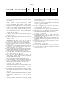
TABLE I
L OCK & K EY AGAINST HACKER CLASSES .
Beginner
Independent
Business
Government
Low
X
Complexity
Med
High
X
X
X
X
X
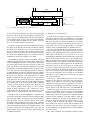
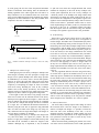
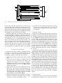
prolong test time by an exorbitant amount. Only the initial
setup placing the TSC into secure mode affects test time. After
test mode has been properly secured and setup, testing the
CUT is no different from standard scan test. The total test
time (j ) would take
(2)
jkml#3=onk+g!pq
rts eutv nk:w= !xnyzn{$|
where is the number of subchains, is the length of each
subchain, rts
eu is the number of combinational vectors, is
the size of the test key, and is the size of the LFSR. The
significance of and decreases as }d and the number
of test rounds increase. With insignificant and values, the
test time becomes solely dependent upon }~ and rts .
eu
Since ' is the total length of the scan chain, we can
replace it with simplifying the equation further making
the total test time no different for the Lock & Key technique
from traditional scan test.
jkm:=on+!pq
rts eu k
n :w= !
jkm: nk+g!p
rts eu
n (3)
(4)
C. Area Overhead
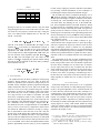
We synthesized our Lock & Key technique in Verilog using
Synopsys’ Design Analyzer tool [32]. Table II shows the
number of equivalent gates returned by Design Analyzer for
the FSM, test key comparator, primitive polynomial configured
LFSR, and decoder with 4-bit, 8-bit, and 12-bit LFSRs. The
total size of the Lock & Key method along with overhead
percentages for ISCAS’89 benchmarks s38417 and s38584.
The Lock & Key test security controller grows fairly slowly
for a large increase in the number of subchains. The FSM
and test key comparator remain a fairly constant size. FSM
operation is mostly independent of size of the LFSR. The test
key comparator is only dependent upon the size of the test key.
1
For a minimally secure test key length, a length of
bits should be used. For our implementation, we used a " -bit
test key. The size of the test key comparator in Table II does
not include the additional overhead for on-chip key storage,
but we did include it in the final size of the TSC. Only the
growth of the LFSR and decoder significantly affect the size,
but the number of subchains that can be used exponentially
increases with each additional bit. The total size of each LFSR
includes the V -bits used for insecure mode operation. We chose
to use a constant V value of for all implementations and the
primitive polynomials used were from [3]. A fair comparison
to other works [15][26][27] cannot be made due to the authors
not providing overhead information of their techniques or
performing their analysis different benchmark designs.
A -bit LFSR can control 15 subchains placing any one of
+gf`hi different subchain combinations on SO while insecure.
Without prior knowledge, a beginner would have little chance
of hacking any vital information from the chip using the
scan chain alone. By doubling the size of the LFSR to bits, most independent hackers and small businesses should
be deterred with the exponential increase in the number of
subchains and security. Increasing the LFSR size again will
greatly increase the amount of security, but at the cost of a
much larger area overhead due to the exponential
growth of the
1
decoder. Increasing the size beyond + -bits risks producing a
fairly large overhead for a level of security that an -bit LFSR
may adequately provide.
Regardless of the size of the LFSR, if business or government hackers have enough resources to open the package
and reverse engineer the layout, any effort to secure the scan
chain is inadequate, which is common for any individual
side-channel countermeasure. However, we suggest that design
engineers use multiple design security techniques to force both
business and government hackers to spend more time, money,
and other resources to eventually make the costs outweigh any
gains.
The components for the TSC are fairly standard and testing
it with BIST can provide a fairly high coverage. Using scanbased testing would result in the side-channel exposure that
the Lock & Key technique tries to protect since it could be
used to expose either the test key or random seed. The other
option would be to simply not test the TSC logic at all since it
is part of the testing logic for the CUT. This option is similar
in nature to the choice of ignoring to test BIST logic due to
the fact that if the CUT returns an incorrect result, the chip is
faulty regardless of whether the CUT is faulty or the TSC is
faulty [3].
VI. C ONCLUSION
Scan-based designs have been proven to be a significant
security risk to the contents of a chip. Without proper security
in place, encryption algorithms can be weakened and IP can
be stolen. We have proposed the Lock & Key technique as a
countermeasure to the method that has been used to expose
vital information through the scan chain. Unless the user is
trusted, our technique will cause the scan chain to operate
unpredictably and make exploitation very difficult. Design of
the technique is flexible and straight forward to implement for
varying degrees of security. Until another method of testing
a chip can yield the similar coverage as scan based designs
with better security, flexible, low-overhead solutions must be
included in the design of scan.
R EFERENCES
[1] Y. Zorian, E. J. Marinissen, and S. Dey, “Testing Embedded-Core Based
System Chips,” in Proc. of Intl. Test Conf., 1998, pp. 130–143.
[2] Y. Zorian, S. Dey, and M. Rodgers, “Test of Future System-on-Chips,”
in Proc. of Intl. Test Conf., 2000, pp. 392–398.
[3] M. L. Bushnell and V. D. Agrawal, Essentials of Electronic Testing.
Kluwer Academic Publishers, 2000.