1
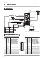
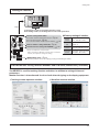
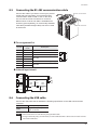
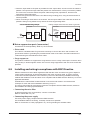
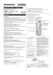
Connection 8.5 Connecting the RS-485 communication cable Drivers can be linked. Connect this cable if you want to control your product via RS-485 communication. Connect the RS-485 communication cable to CN6 or CN7 on the driver. You can use the vacant connectors to connect a different driver. A driver link cable is available as an accessory (sold separately). A commercially-available LAN cable (shielded straight cable) can also be used to link drivers. CN6/CN7 connector Pin assignment list Pin No. 1 2 3 4 5 6 7 8 Signal name N.C. GND TR+ N.C. N.C. TR− N.C. N.C. Description Not used GND RS-485 communication signal (+) Not used 1 • • • • • 8 RS-485 communication signal (−) Not used Internal input circuit 2 GND 3 TR+ 6 TR5V SW1 No.4 2 GND 3 TR+ 1 kΩ 120 Ω 6 TR- SW1 No.3 1 kΩ 0V 0V 8.6 Connecting the USB cable Connect the USB cable that is satisfied the following specification to the USB communication connector. Specification Cable Note USB2.0 (Full Speed) Length: 3 m (9.8 ft.) or less Type: A−mini-B Connect the driver and PC directly using the USB cable. In large electrically noisy environments, use the USB cable with a ferrite core or install a ferrite core to the USB cable. −21−