1
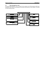
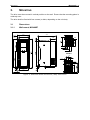
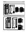
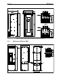
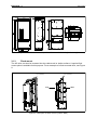
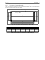
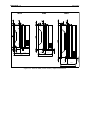
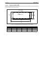
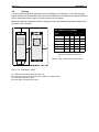
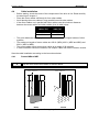
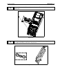
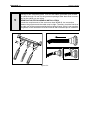
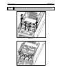
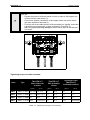
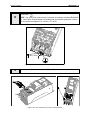
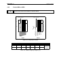
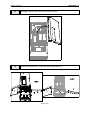
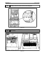
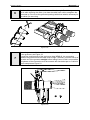
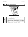
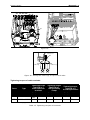
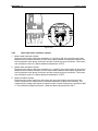
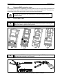
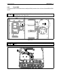
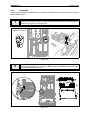
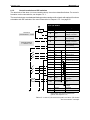
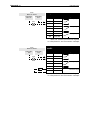
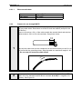
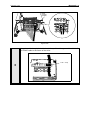
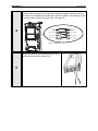
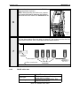
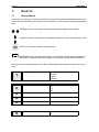
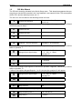
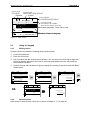
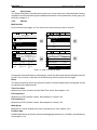
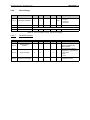
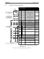
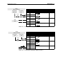
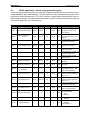
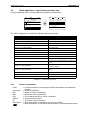
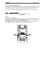
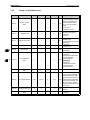
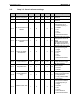
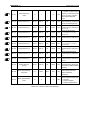
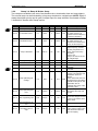
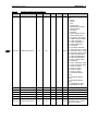
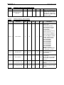
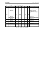
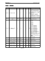
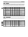
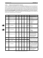
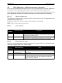
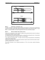
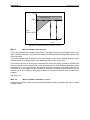
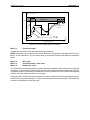
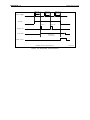
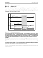
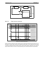
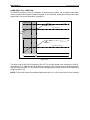
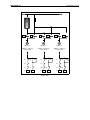
Honeywell • 32 HVAC APPLICATION EXAMPLE: You want to connect the Control signal 2 A (parameter M3.5.1.2) to digital input DI2 on Basic I/O board. 1 STOP Locate the parameter Control signal 2 A (M3.5.1.2) on the keypad. READY Keypad ID: M3 Quick Setup ( 17 ) Monitor ( 5 ) Parameters ( 12 ) STOP READY STOP Main Menu READY Keypad ID: STOP READY Parameters M3.5 References ( 18 ) Ramps and Brakes ( 7 ) I/O Config ( 4 ) Keypad I/O Config ID: M3.5.1 Digital Inputs ( 26 ) Analog Inputs ( 36 ) Digital Outputs ( 1 ) Keypad Digital Inputs ID:404 M3.5.1.2 Ctrl Signal 1 A DigIn SlotA.1 Ctrl Signal 2 A DigIn Slot0.1 Ctrl Signal 1 B DigIn Slot0.1 2 STOP Enter the Edit mode. READY Keypad Digital Inputs ID:404 M3.5.1.2 STOP READY Keypad Ctrl signal 2 A ID: M3.5.1.2 Ctrl Signal 1 A DigIn SlotA.1 Edit Ctrl Signal 2 A DigIn Slot0.1 Help Ctrl Signal 1 B DigIn Slot0.1 Add to favorites STOP Keypad Ctrl signal 2 A M3.5.1.2 DigIN SlotA.2 Min: Max: 3 READY ID:404 DigIN Slot0 DigIN SlotA DigIN SlotB DigIN SlotC DigIN SlotD DigIN SlotE TimeChannel Fieldbus CW LLP signal 0-10 Varies Varies Varies Varies Varies 1-3 0-31 1-5 Change the value: The editable part of the value (DigIN Slot0) is underlined and blinking. Change the slot or assign the signal to Time Channel with the arrow keys up and down. Make the terminal value (.1) editable by pressing the right key once and change the value with arrow keys up and down. Accept the change with OK button or return to previous menu level with BACK/ RESET button.