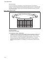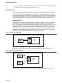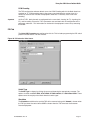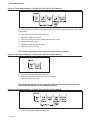
1
Telecom
Simulation
Platform
User’s Manual
Part No.: 40-400-00049
Revision: H
Copyright Notice
Copyright © 2001 Teltone Corporation
All Rights Reserved
Trademarks
Teltone is registered trademarks of Teltone Corporation.
TSP is a trademark of Teltone Corporation.
Windows is a registered trademark of Microsoft Corporation.
Other company and product names may be trademarks or
registered trademarks of their respective owners.
Teltone Corporation
rd
22116 – 23 Drive SE
Bothell, Washington 98021-4413 USA
Customer Service: 425-951-3388
Technical Support: 425-951-3390
Fax:425-487-2288
E-mail: [email protected]
Web Site: www.teltone.com
Contents
IMPORTANT USER SAFETY INSTRUCTIONS . . . . . . . . . . . . . . . . . . . . . . . . . . . . . . . . . . . . . . vi
REGULATORY COMPLIANCE . . . . . . . . . . . . . . . . . . . . . . . . . . . . . . . . . . . . . . . . . . . . . . . . . . vi
Overview . . . . . . . . . . . . . . . . . . . . . . . . . . . . . . . . . . . . . . . . . . . . . . . . . . . . . . . . . . . . . . . . . . . . 1
Standard Features (TSP-Base). . . . . . . . . . . . . . . . . . . . . . . . . . . . . . . . . . . . . . . . . . . . . . . . 1
Hardware Options . . . . . . . . . . . . . . . . . . . . . . . . . . . . . . . . . . . . . . . . . . . . . . . . . . . . . . . . . . 2
Software Options. . . . . . . . . . . . . . . . . . . . . . . . . . . . . . . . . . . . . . . . . . . . . . . . . . . . . . . . . . . 2
System Requirements. . . . . . . . . . . . . . . . . . . . . . . . . . . . . . . . . . . . . . . . . . . . . . . . . . . . . . . 2
Power Requirements . . . . . . . . . . . . . . . . . . . . . . . . . . . . . . . . . . . . . . . . . . . . . . . . . . . . 2
Operating System Requirements . . . . . . . . . . . . . . . . . . . . . . . . . . . . . . . . . . . . . . . . . . . 3
Connections . . . . . . . . . . . . . . . . . . . . . . . . . . . . . . . . . . . . . . . . . . . . . . . . . . . . . . . . . . . 3
Simulation Interfaces . . . . . . . . . . . . . . . . . . . . . . . . . . . . . . . . . . . . . . . . . . . . . . . . . . . . 4
4 and 8 Channel POTS Modules . . . . . . . . . . . . . . . . . . . . . . . . . . . . . . . . . . . . . . . . . . . 6
Getting Started . . . . . . . . . . . . . . . . . . . . . . . . . . . . . . . . . . . . . . . . . . . . . . . . . . . . . . . . . . . . . . . 7
Check your TSP package . . . . . . . . . . . . . . . . . . . . . . . . . . . . . . . . . . . . . . . . . . . . . . . . . . . . 7
Optional Hardware . . . . . . . . . . . . . . . . . . . . . . . . . . . . . . . . . . . . . . . . . . . . . . . . . . . . . . 7
Optional Software Modules . . . . . . . . . . . . . . . . . . . . . . . . . . . . . . . . . . . . . . . . . . . . . . . 7
Configuring the TSP Hardware/Software . . . . . . . . . . . . . . . . . . . . . . . . . . . . . . . . . . . . . . . . . . . 8
Module Interface Matrix (Required Set-up) . . . . . . . . . . . . . . . . . . . . . . . . . . . . . . . . . . . . . . . 8
Basic Hardware setup . . . . . . . . . . . . . . . . . . . . . . . . . . . . . . . . . . . . . . . . . . . . . . . . . . . 8
Power up the TSP . . . . . . . . . . . . . . . . . . . . . . . . . . . . . . . . . . . . . . . . . . . . . . . . . . . . . . . . . . 8
Software Installation Instructions . . . . . . . . . . . . . . . . . . . . . . . . . . . . . . . . . . . . . . . . . . . . . . 9
Operational Strategy . . . . . . . . . . . . . . . . . . . . . . . . . . . . . . . . . . . . . . . . . . . . . . . . . . . . . . . . 9
Quick Start . . . . . . . . . . . . . . . . . . . . . . . . . . . . . . . . . . . . . . . . . . . . . . . . . . . . . . . . . . . . . . . 9
Hardware and Software Setup . . . . . . . . . . . . . . . . . . . . . . . . . . . . . . . . . . . . . . . . . . . . . 9
Units Configuration . . . . . . . . . . . . . . . . . . . . . . . . . . . . . . . . . . . . . . . . . . . . . . . . . . . . . 10
Module Configuration . . . . . . . . . . . . . . . . . . . . . . . . . . . . . . . . . . . . . . . . . . . . . . . . . . . 10
Templates Configuration . . . . . . . . . . . . . . . . . . . . . . . . . . . . . . . . . . . . . . . . . . . . . . . . 11
Control Sets Configuration . . . . . . . . . . . . . . . . . . . . . . . . . . . . . . . . . . . . . . . . . . . . . . . 11
Simulation Types. . . . . . . . . . . . . . . . . . . . . . . . . . . . . . . . . . . . . . . . . . . . . . . . . . . . . . . . . . 12
End-to-End Calls . . . . . . . . . . . . . . . . . . . . . . . . . . . . . . . . . . . . . . . . . . . . . . . . . . . . . . 12
Call Originate and Call Terminate . . . . . . . . . . . . . . . . . . . . . . . . . . . . . . . . . . . . . . . . . 13
Programming the TSP . . . . . . . . . . . . . . . . . . . . . . . . . . . . . . . . . . . . . . . . . . . . . . . . . . . . . . . . . 15
Telecom Simulation Platform (TSP) main screen . . . . . . . . . . . . . . . . . . . . . . . . . . . . . . . . . 15
Tree Display . . . . . . . . . . . . . . . . . . . . . . . . . . . . . . . . . . . . . . . . . . . . . . . . . . . . . . . . . . 15
Information Section. . . . . . . . . . . . . . . . . . . . . . . . . . . . . . . . . . . . . . . . . . . . . . . . . . . . . 15
Control Set Enables . . . . . . . . . . . . . . . . . . . . . . . . . . . . . . . . . . . . . . . . . . . . . . . . . . . . 16
Units . . . . . . . . . . . . . . . . . . . . . . . . . . . . . . . . . . . . . . . . . . . . . . . . . . . . . . . . . . . . . . . . . . . 16
Serial Connection . . . . . . . . . . . . . . . . . . . . . . . . . . . . . . . . . . . . . . . . . . . . . . . . . . . . . . 17
40-400-00049, Rev. G
Page iii
Telecom Simulation Platform
Authorization Code . . . . . . . . . . . . . . . . . . . . . . . . . . . . . . . . . . . . . . . . . . . . . . . . . . . . . 18
Software Updates . . . . . . . . . . . . . . . . . . . . . . . . . . . . . . . . . . . . . . . . . . . . . . . . . . . . . . 18
Network Connection . . . . . . . . . . . . . . . . . . . . . . . . . . . . . . . . . . . . . . . . . . . . . . . . . . . . 18
Slot Tabs . . . . . . . . . . . . . . . . . . . . . . . . . . . . . . . . . . . . . . . . . . . . . . . . . . . . . . . . . . . . 20
Single T1/E1 and Dual T1/E1 Card Types . . . . . . . . . . . . . . . . . . . . . . . . . . . . . . . . . . . 20
The 4 and 8 Channel POTS Card Types . . . . . . . . . . . . . . . . . . . . . . . . . . . . . . . . . . . . 24
Channels Tab . . . . . . . . . . . . . . . . . . . . . . . . . . . . . . . . . . . . . . . . . . . . . . . . . . . . . . . . . 24
Channel Configuration Wizard . . . . . . . . . . . . . . . . . . . . . . . . . . . . . . . . . . . . . . . . . . . . 26
T1/E1 Alarms . . . . . . . . . . . . . . . . . . . . . . . . . . . . . . . . . . . . . . . . . . . . . . . . . . . . . . . . . 27
Templates . . . . . . . . . . . . . . . . . . . . . . . . . . . . . . . . . . . . . . . . . . . . . . . . . . . . . . . . . . . . . . . 29
Type Tab . . . . . . . . . . . . . . . . . . . . . . . . . . . . . . . . . . . . . . . . . . . . . . . . . . . . . . . . . . . . 29
Channel Protocols . . . . . . . . . . . . . . . . . . . . . . . . . . . . . . . . . . . . . . . . . . . . . . . . . . . . . 30
Timings Tab . . . . . . . . . . . . . . . . . . . . . . . . . . . . . . . . . . . . . . . . . . . . . . . . . . . . . . . . . . 32
Signaling Tab . . . . . . . . . . . . . . . . . . . . . . . . . . . . . . . . . . . . . . . . . . . . . . . . . . . . . . . . . 33
Control Sets . . . . . . . . . . . . . . . . . . . . . . . . . . . . . . . . . . . . . . . . . . . . . . . . . . . . . . . . . . . . . 34
Control Set Type Field . . . . . . . . . . . . . . . . . . . . . . . . . . . . . . . . . . . . . . . . . . . . . . . . . . 35
Template Field . . . . . . . . . . . . . . . . . . . . . . . . . . . . . . . . . . . . . . . . . . . . . . . . . . . . . . . . 36
Channel Assignments. . . . . . . . . . . . . . . . . . . . . . . . . . . . . . . . . . . . . . . . . . . . . . . . . . . 37
Executing a Simulation . . . . . . . . . . . . . . . . . . . . . . . . . . . . . . . . . . . . . . . . . . . . . . . . . . 39
End-to-End Control Set Example . . . . . . . . . . . . . . . . . . . . . . . . . . . . . . . . . . . . . . . . . . 41
Event Log screen. . . . . . . . . . . . . . . . . . . . . . . . . . . . . . . . . . . . . . . . . . . . . . . . . . . . . . . . . . . . . 43
Options Screen . . . . . . . . . . . . . . . . . . . . . . . . . . . . . . . . . . . . . . . . . . . . . . . . . . . . . . . . . . . . . . 45
Alerts Tab . . . . . . . . . . . . . . . . . . . . . . . . . . . . . . . . . . . . . . . . . . . . . . . . . . . . . . . . . . . . 45
Upgrades Tab . . . . . . . . . . . . . . . . . . . . . . . . . . . . . . . . . . . . . . . . . . . . . . . . . . . . . . . . . 45
TSP Diagnostics . . . . . . . . . . . . . . . . . . . . . . . . . . . . . . . . . . . . . . . . . . . . . . . . . . . . . . . . . . . . . 46
TSP Trace . . . . . . . . . . . . . . . . . . . . . . . . . . . . . . . . . . . . . . . . . . . . . . . . . . . . . . . . . . . . . . . . . . 48
Primary Rate ISDN Software Module (TSP-PRI) . . . . . . . . . . . . . . . . . . . . . . . . . . . . . . . . . . . . 49
T1 Tab. . . . . . . . . . . . . . . . . . . . . . . . . . . . . . . . . . . . . . . . . . . . . . . . . . . . . . . . . . . . . . . . . . 49
Clock. . . . . . . . . . . . . . . . . . . . . . . . . . . . . . . . . . . . . . . . . . . . . . . . . . . . . . . . . . . . . . . . 50
Framing . . . . . . . . . . . . . . . . . . . . . . . . . . . . . . . . . . . . . . . . . . . . . . . . . . . . . . . . . . . . . 50
Line Coding . . . . . . . . . . . . . . . . . . . . . . . . . . . . . . . . . . . . . . . . . . . . . . . . . . . . . . . . . . 50
PCM Encoding . . . . . . . . . . . . . . . . . . . . . . . . . . . . . . . . . . . . . . . . . . . . . . . . . . . . . . . . 51
PRI Tab . . . . . . . . . . . . . . . . . . . . . . . . . . . . . . . . . . . . . . . . . . . . . . . . . . . . . . . . . . . . . . . . . 51
Switch Type . . . . . . . . . . . . . . . . . . . . . . . . . . . . . . . . . . . . . . . . . . . . . . . . . . . . . . . . . . 51
Simulation . . . . . . . . . . . . . . . . . . . . . . . . . . . . . . . . . . . . . . . . . . . . . . . . . . . . . . . . . . . . 51
Channels Tab . . . . . . . . . . . . . . . . . . . . . . . . . . . . . . . . . . . . . . . . . . . . . . . . . . . . . . . . . . . . 52
Subaddress . . . . . . . . . . . . . . . . . . . . . . . . . . . . . . . . . . . . . . . . . . . . . . . . . . . . . . . . . . 52
Calling and Called Number. . . . . . . . . . . . . . . . . . . . . . . . . . . . . . . . . . . . . . . . . . . . . . . 52
Templates . . . . . . . . . . . . . . . . . . . . . . . . . . . . . . . . . . . . . . . . . . . . . . . . . . . . . . . . . . . . 52
Troubleshooting. . . . . . . . . . . . . . . . . . . . . . . . . . . . . . . . . . . . . . . . . . . . . . . . . . . . . . . . . . . . . . 54
Icon Legend. . . . . . . . . . . . . . . . . . . . . . . . . . . . . . . . . . . . . . . . . . . . . . . . . . . . . . . . . . . . . . . . . 57
Appendix 1. . . . . . . . . . . . . . . . . . . . . . . . . . . . . . . . . . . . . . . . . . . . . . . . . . . . . . . . . . . . . . . . . . 58
Page iv
Contents
Timings Tab for Analog LS, T1/E1 GS FXS, and T1/E1 LS FXS . . . . . . . . . . . . . . . . . . 58
Call Process Flowcharts for Analog LS, T1/E1 GS FXS or T1/E1 LS FXS . . . . . . . . . . 59
Timings Tab for E1 ITU Q.421 . . . . . . . . . . . . . . . . . . . . . . . . . . . . . . . . . . . . . . . . . . . . 61
Call Process Flowcharts for E1 ITU Q.421 . . . . . . . . . . . . . . . . . . . . . . . . . . . . . . . . . . . 62
Timings Tab for T1/E1 GS FXO and T1/E1 LS FXO . . . . . . . . . . . . . . . . . . . . . . . . . . . 64
Timings Tab for T1/E1 Immediate Dial . . . . . . . . . . . . . . . . . . . . . . . . . . . . . . . . . . . . . . 65
Call Terminate T1/E1 Immediate . . . . . . . . . . . . . . . . . . . . . . . . . . . . . . . . . . . . . . . . . . 66
Timings tab for T1/E1 Delay Dial and T1/E1 Wink Start. . . . . . . . . . . . . . . . . . . . . . . . . 67
Call Process Flow Charts for T1/E1 Wink and Delay Dial . . . . . . . . . . . . . . . . . . . . . . . 69
Timings Tab for T1 PRI (CPE) . . . . . . . . . . . . . . . . . . . . . . . . . . . . . . . . . . . . . . . . . . . . 70
Timings Tab for T1 PRI (Network) . . . . . . . . . . . . . . . . . . . . . . . . . . . . . . . . . . . . . . . . . 71
Glossary of Terms . . . . . . . . . . . . . . . . . . . . . . . . . . . . . . . . . . . . . . . . . . . . . . . . . . . . . . . . . . . . 73
References . . . . . . . . . . . . . . . . . . . . . . . . . . . . . . . . . . . . . . . . . . . . . . . . . . . . . . . . . . . . . . . . . 77
Revision History. . . . . . . . . . . . . . . . . . . . . . . . . . . . . . . . . . . . . . . . . . . . . . . . . . . . . . . . . . . . . . 78
Warranty and Service . . . . . . . . . . . . . . . . . . . . . . . . . . . . . . . . . . . . . . . . . . . . . . . . . . . . . . . . . 79
Warranty Information. . . . . . . . . . . . . . . . . . . . . . . . . . . . . . . . . . . . . . . . . . . . . . . . . . . . . . . 79
Return Procedures . . . . . . . . . . . . . . . . . . . . . . . . . . . . . . . . . . . . . . . . . . . . . . . . . . . . . . . . 79
Technical Assistance . . . . . . . . . . . . . . . . . . . . . . . . . . . . . . . . . . . . . . . . . . . . . . . . . . . . . . 79
Maintenance . . . . . . . . . . . . . . . . . . . . . . . . . . . . . . . . . . . . . . . . . . . . . . . . . . . . . . . . . . . . . 79
Cleaning . . . . . . . . . . . . . . . . . . . . . . . . . . . . . . . . . . . . . . . . . . . . . . . . . . . . . . . . . . . . . 79
Servicing . . . . . . . . . . . . . . . . . . . . . . . . . . . . . . . . . . . . . . . . . . . . . . . . . . . . . . . . . . . . . 79
Ordering Information . . . . . . . . . . . . . . . . . . . . . . . . . . . . . . . . . . . . . . . . . . . . . . . . . . . . . . . . . . 80
Specifications . . . . . . . . . . . . . . . . . . . . . . . . . . . . . . . . . . . . . . . . . . . . . . . . . . . . . . . . . . . . . . . 81
Index . . . . . . . . . . . . . . . . . . . . . . . . . . . . . . . . . . . . . . . . . . . . . . . . . . . . . . . . . . . . . . . . . . . . . . 83
40-400-00049, Rev. H
Page v
IMPORTANT USER SAFETY INSTRUCTIONS
When using your equipment, basic safety precautions should always be followed to reduce the risk of fire, electric
shock, and injury to persons, including the following:
1. Read and understand all instructions.
2. Follow all warnings and instructions marked on the product.
3. This product should be operated only from the type of power source indicated on the marking label. If you are
not sure of the type of power supply, consult your dealer or local power company. Product designed for indoor use
only.
4. To reduce the risk of electric shock, do not disassemble this product, but take it to a qualified serviceman when
some service or repair work is required. Opening or removing covers may expose you to dangerous voltages or
other risks. Incorrect reassembly can cause electric shock when the appliance is subsequently used.
5. If the product does not operate normally by following the operating instructions, or if the product has been
dropped or the cabinet has been damaged, or if the product exhibits a distinct change in performance; refer
servicing to qualified service personnel.
6. If this product is used in a manner other than specified in this manual, the protection provided by the product
may be impaired.
7. The IEC 320 connecter (power input) is the main power disconnect point, for the purpose of removing power
from the unit. Pull the power cord away from the connector to assure power disconnect.
8. Adequate air flow must be maintained in order for the unit to operate correctly. Do not wrap the unit in blankets,
paper, or other material that may impede ventilation.
REGULATORY COMPLIANCE
FCC Part 15 : This equipment has been tested and found to comply with the limits for a Class A digital device,
pursuant to Part 15 of the FCC Rules. These limits are designed to provide reasonable protection against harmful
interference in a residential installation. This equipment generates, uses, and can radiate radio frequency energy
and, if not installed and used in accordance with the instructions, may cause harmful interference to radio
communications. However, there is no guarantee that interference will not occur in a particular installation. If this
equipment does cause harmful interference to radio or television reception, which can be determined by turning
the equipment off and on, the user is encouraged to try to correct the interference by one or more of the following
measures:
·
Reorient or relocate the receiving antenna.
·
Increase the separation between the equipment and receiver.
·
Connect the equipment to an outlet on a circuit different from that to which the receiver is
connected.
·
Consult the dealer or an experienced radio/TV technician for help.
The Installation Category (OVER VOLTAGE CATEGORY) for this device is II and it is designed to be safe under
POLLUTION DEGREE 2, per IEC 1010-1: 1990 specifications.
Page vi
Overview
The Teltone TSP (Telecom Simulation Platform) is a combined hardware and software platform
used to simulate connections to different telephony interfaces. These include T1, E1, and Analog
POTS, and in the future, other interfaces. The AC power input is universal, accepting 90 to 250
VAC, from 43 to 63 Hz. An RS-232 port connection is used to configure the TSP.
Standard Features (TSP-Base)
·
·
·
·
·
·
·
·
·
·
·
·
·
·
Base unit for configuring with optional hardware modules
Upgradeable software and hardware modular design
Able to connect multiple TSP’s to a single computer
Analog POTS and T1/E1 simulation in the same system
Operates under Windows 95/98/2000 or Windows NT
Programming and control can be done with either the serial or ethernet connection
Status Display provides current state for each channel (on/off-hook, ringing, etc)
Supports three call types
· Originate – calls placed by the TSP to a connected device
· Terminate – calls placed into the TSP by a connected device
· End-to-End – calls placed through the TSP by one device to another
Call progress and DTMF signaling by playback of audio files
Event Logging of
· On/off-hook
· Ringing
· Time to answer
· Call duration
· Errors such as T1/E1 loss of sync
· Date/time of each event
Programmable Call Parameters
· T1 channel type (robbed bit signaling): Loop Start, Ground Start, Immediate Dial, Wink
Start, Delay Dial
· E1 channel signaling including: CAS Q.421 with DTMF Variation, Loop Start, Ground
Start, Wink, Immediate Dial, Delay Dial
· CAMA or Tie Trunk operation
· Programmable T1 and E1 signaling bit states for A, B, C & D bits
· T1/E1 Clear channel “nailed up” 64 KB/s connection
· Analog channel type: Loop Start only
· Call Timing: Call Duration, Guard Time, Far-end Disconnect Time, Delay Before Audio
Message
· Dial String: ANI/DNIS Transmit Digits –40 Digits, Phone Number –40 Digits. Dialing
Order (available soon)
· Dial Tone: Enable, Delay Before, Length
· Ringback: Enable, Duration
Bulk Call Generation
Diagnostics with ability to place channels in different signaling states and shows the signaling
bit states on T1/E1
Trace for detailed call progress of a channel
40-400-00049, Rev. G
Page 1
Telecom Simulation Platform
Hardware Options
·
·
·
·
TSP Single T1/E1 module
TSP Dual T1/E1 module
TSP 4 Channel POTS module
TSP 8 Channel POTS module
Software Options
TSP-PRI (Primary Rate ISDN)
Basic unit feature plus:
·
·
·
Multiple switch types, which include:
· US National ISDN-2
· AT&T 4ESS
· AT&T 5ESS
· NT DMS-100/250
Simulates CPE end or Network end
Provides the following Supplementary Services:
· Direct dialing in (DDI)
· Subaddressing
· Delivery of Called and Caller number (CLIP)
· Delivery of Type of Address and Numbering Plan
System Requirements
Power Requirements
AC operating power must be within 90 to 250 Volts AC and the operating frequency from 43 to 63
Hz. A standard North American plug is provided with the unit, although the TSP base unit uses an
industry standard IEC three prong connector so that almost any international power plug can be
used.
Figure 1 TSP-A-01
Page 2
Overview
Operating System Requirements
The PC Configuration software will operate on Windows 95/98/2000 and Windows NT. The
following minimum disk storage capacities are required for the basic installation and storage of
saved files:
6 Mb required on the disk with the Windows operating system
4 Mb required on the disk the application is installed on
7 Mb additional required to install the Adobe Acrobat reader
Connections
Configuring and control of the TSP can be done with either a serial connection to a PC or with an
Ethernet connection directly to a PC or to a LAN. It is necessary to use the serial connection to
initially program the IP for the Ethernet connection.
Important
When using the T1/E1 module in T1-PRI mode, the network connection must be used for
programming and control; the serial connection is not allowed. This allows for enhanced
messaging during PRI operation.
Serial connection
The connection is an RJ-11 port using an RJ-14 standard on the TSP chassis, mating to a DB-9
or DB-25 connector (on the PC) and supports control leads Tx Data, Rx Data, and Ground. Refer
to Figure 2 for cable pinouts. Refer to Figure 3 for port connections.
Important
Initial programming of the TSP must be done with this connection
Figure 2 Serial Cable RJ-14 to RJ-14
Figure 3 RJ-14 Port Connections
Serial Connection
40-400-00049, Rev. G
Ethernet Connection
Page 3
Telecom Simulation Platform
Ethernet connection
The network connection is a 10/100 base T using an RJ-45 connector. This connection is
necessary for downloading voice messages and software updates to the TSP. The Ethernet cable
provided is a cross-over cable and is only used when connecting directly to a PC. Refer to Figure
4 for cable pinouts. Refer to Figure 3 for port connections. See Network Connection in the Units
section for more details.
Figure 4 Ethernet Cross-over cable
RJ-45 Connector 1
RJ-45 Connector 2
1
Pair 2 (T2)
Tx +
3
White/Orange
2
Pair 2 (R2)
Tx -
6
Orange
Rx -
3
Pair 3 (T3)
Rx +
1
White/Green
Tx +
4
Pair 1 (R1)
4
Blue
5
Pair 1 (T1)
5
White/Blue
6
Pair 3 (R3)
7
8
Rx -
2
Green
Pair 4 (T4)
7
White/Brown
Pair 4 (R4)
8
Brown
Rx +
Tx -
Simulation Interfaces
Single and Dual T1/E1 Modules
Cable requirements, Pinouts, Technical Specs
· The Single T1/E1 and Dual T1/E1 interface modules support a line build-out of either 0-133 ft,
134-266 ft, 267-399 ft, or 400-533 ft for connection to real cable installations. An alternate
choice for line build-out is defining the loss characteristics of -7.5 dB, -15 dB, or -22.5 dB.
Physical connection is via an RJ-45 configured to RJ-48C standard (pin 1- Rx ring, Pin 2- Rx
tip, pin 4- Tx ring, pin 5- Tx tip). Framing options include D4 or ESF for T1. E1 features
include signaling options of FAS, CAS with the option for CRC-4. Line Coding options are
AMI with the option for B8ZS on T1 and HDB3 for E1. Clocking options are either internal or
external.
Page 4
Overview
Figure 5 T1/E1 Cable
DTE
DTE
RJ-45 Connector 1
Important:
RJ-45 Connector 2
1
White/Orange Rx Ring
4
White/Orange Tx Ring
2
Orange
3
White/Green
Rx Tip
5
Orange
NC
3
-
4
Blue
Tx Ring
1
Blue
5
White/Blue
Tx Tip
2
White/Blue
6
Green
NC
6
-
NC
7
White/Brown
NC
7
-
NC
8
Brown
NC
8
Tx Tip
NC
Rx Ring
Rx Tip
A shielded T1/E1 cable must be used for the TSP to be FCC Part 15 compliant.
The Single T1/E1 Module looks like the Dual T1/E1 Module except there is only one port. See
Figure 6.
Figure 6 Dual T1/E1 Module
LINK
ERR
This LED indicator shows that the T1/E1 link is active
This LED indicator shows that an error has occurred
40-400-00049, Rev. G
Page 5
Telecom Simulation Platform
4 and 8 Channel POTS Modules
4 Channel POTS Module
Cable requirements, Pinouts, Technical Specs
·
The 4 Channel POTS interface module will use industry standard RJ-11 jacks and the wiring
also meets industry standards, using Pins 3 and 4 for Tip and Ring. Pins 1,2,5, and 6 have no
connection.
The 4 channel POTS module is identical to the 8 channel module, except there is only 1 channel
available per port. See Figure 7.
8 Channel POTS Module
Cable Requirements, Pinouts, Technical Specs
·
The 8 Channel POTS interface module will use industry standard RJ-11 jacks and is wired to
RJ-14 standards, using Pins 3 and 4 for Tip & Ring for the first line, and pins 2 and 5 for Tip
& Ring for the second line. Pins 1 and 6 will have no connection.
Figure 7 8 Channel POTS Module
Page 6
Getting Started
Check your TSP package
When you receive your TSP (Telecom Simulation Platform), you will receive the following
components:
Your basic package should include the following items:
·
·
·
·
·
·
·
·
·
·
TSP-BASE-01 unit
120 VAC power cord
RJ-45 Ethernet cross over cable (gray cable, labeled)
RJ-14 - RS-232 cable (RJ-11 connector on each end)
RJ-14 - DB-9 adapter
RJ-14 - DB-25 adapter
Two RJ-45 - T1/E1 cables (yellow cable, labeled)
Base Configuration Software (CD-ROM)
Product Registration Card
At least 1 Optional Hardware Module
Optional Hardware
·
·
·
·
·
Single T1/E1 interface module
Dual T1/E1 interface module
4 Channel POTS interface module
8 Channel POTS interface module
Y-Cable Kit (set of 4)
Optional Software Modules
·
TSP-PRI, T1 Primary Rate ISDN software module
If any of the items you ordered are missing or damaged, contact Teltone’s Customer Service
department at 425-951-3388.
The TSP modules are ESD (electro-static discharge) sensitive devices and are shipped in static
shield packaging. Proper precautions are needed to avoid damaging them when handled. Teltone
Corporation requires any returned modules to be properly packaged in static shield packaging.
40-400-00049, Rev. G
Page 7
Configuring the TSP Hardware/Software
Module Interface Matrix (Required Set-up)
Table 1 Module Interface Matrix
Slot 2
Slot 3
Slots 1 & 4
T1/E1
not used
One 4 or 8 Channel POTS module
not used
POTS
Future Use
(Note 1)
Future use
Two Single T1/E1 modules (Note 2)
T1/E1
T1/E1
Future use
One Single T1/E1 or Dual T1/E1 and one 4 or 8 Channel
POTS module
T1/E1
POTS
Future use
Two 4 or 8 Channel POTS modules (note 3)
POTS
POTS
Future use
One Single T1/E1 or Dual T1/E1 module
Note 1:
Note 2:
Note 3:
Only slots 2 and 3 are supported at this time
The TSP does not support two Dual T1/E1 modules.
If using both a 4 Channel POTS and a 8 Channel POTS module, Teltone recommends placing the 4 Channel
POTS module in Slot 2 and the 8 Channel POTS module in Slot 3.
Slot count is 1-4 from left to right when looking at the back of the TSP.
Modules must be installed per the matrix before the TSP is powered on. Call setup scenarios that
are configured via the PC software are dependent upon the order in which modules are installed.
For example, configurations that are created when slot 2 has a T1/E1 module installed and slot 3
has a POTS module installed, will not be recognized as valid if the modules are moved to
different positions. Therefore it is always necessary to follow the required installation order
specified above. The TSP will give an error if the modules are not installed as required in the
matrix.
Basic Hardware setup
Before applying power to the TSP, install the optional modules per the matrix. Ensure they are
securely seated. Connect the CommPort cable (RJ-11 jack at both ends) to the unit at the jack
labeled Console. Connect the other end to the PC using the DB-9 or DB-25 adapter. For the
Ethernet connection, use the provided crossover cable (RJ-45 at both ends) if connecting directly
to the PC. If connecting to the network, a standard Ethernet cable will be needed.
Important
To prevent damage to the POTS modules, the TSP must be powered down for at least 30
minutes before installing or removing the module. This allows for voltage dissipation from the
base unit.
Power up the TSP
Before power-up ensure that the modules are seated firmly in the TSP to prevent damage.
The TSP uses a universal power supply that operates from 90 to 250 VAC, 43 to 63 Hz. Connect
the power cord and turn on the unit using the switch on the back of the unit.
Grounding is assured by using the appropriate (approved) power cord.
The green status LED on the front panel will indicate the status of the system. The LED should be
solid green. If the LED fails to light, disconnect power immediately and contact Teltone Technical
Support at 425-951-3390.
Important
Page 8
Adequate airflow must be maintained in order for the unit to operate correctly. Do not wrap the
unit in blankets, paper or other material that may impede ventilation.
Configuring the TSP/Hardware and Software
Software Installation Instructions
The TSP software is supplied on a CD-ROM disk and uses the common Windows setup routine.
Ensure you have the latest version (Version 2.1 at the time this was written) by going to the
Teltone web site, and verifying the version available under Software Downloads for the TSP or
call Technical Support 425-951-3390.
An autorun facility will initiate the installation process automatically when the CD-ROM is installed
into the disk drive. An alternative method to perform the installation is to insert the CD-ROM, then
select START, RUN, BROWSE, then choose your CD-ROM drive, and the file labeled
SETUP.EXE. Follow the on screen instructions.
Important
It will be necessary to obtain an Authorization Code from Teltone Customer Service after the first
Unit is created with the configuration software to enable testing with the TSP. Once the
Authorization Code is installed, the TSP can be used with any PC using the current configuration
software version. See Authorization Code in the Units section for complete instructions.
For information about the current and previous versions of the software, see page 78.
Operational Strategy
The TSP uses a GUI based configuration software program that allows a user to define the TSP
using Units, Templates, Control Sets, and Options. These parameters are saved as a Project
found on the File menu.
The Unit definition defines the communications interface, the installed hardware and some
generic definitions of each module. The Templates define the channel operating characteristics
and timings. The Control Set definition defines the group(s) of individual channels and their
interactions. Once these items have been defined, a Control Set button will appear. When a
Control Set Enables button is selected, this begins the running of the particular application.
Quick Start
Configuration of the TSP via the Windows GUI is very flexible and allows the user to configure the
TSP in a straightforward manner. This section is to assist in configuring the TSP in minimal time
but is not intended to take the place of the rest of the manual. The basic process for setting up
the unit is described in the following subsections.
Hardware and Software Setup
1. Install the modules as required per the Module Interface Matrix section.
2. Connect the Serial and Ethernet cables according to the Basic Hardware Setup section.
The Ethernet connection is not necessary unless you are prompted that newer code is
available or you are using audio files. See Step 5 in “Units Configuration” if needed.
3. Ensure the modules are firmly seated and connect the power cord to the unit per the Power
up the TSP section. Turn on the TSP.
4. Follow the Software Installation Instructions section of the manual.
5. Launch the Telecom Simulation Platform software.
6. Verify you are using the latest version of the configuration software (Version 2.1 at the time
this was written), by opening the program, going to the Help menu and choosing About TSP.
Confirm the latest version available by going to the Teltone web site at www.teltone.com, and
40-400-00049, Rev. G
Page 9
Telecom Simulation Platform
verifying the version under Software Downloads for the TSP or call Technical Support
425-951-3390.
Units Configuration
1. Choose New on the Units menu and name the TSP. The Units screen will default to Serial
connection.
2. Choose the CommPort of the PC that the TSP is connected to by clicking the arrow next to
None.
3. Use the Query Card Types button on the screen to set the program to match the cards that
are installed in the TSP.
4. Click OK on the Units screen. At this point, you will need to obtain an authorization code
before testing can be done with the TSP. Refer to the Authorization Code section of the
manual for instructions or call Teltone Corporation. (See step 6 in “Hardware and Software
Setup.”)
5. If you are prompted that "Newer code is available" choose No and follow the instructions in
the Software Updates section of the manual. Otherwise go to the next step.
6. Re-open the Units screen by going to the Unit menu and clicking the name given the unit at
the bottom of the drop-down menu.
Module Configuration
1. If a T1/E1 module is not being used skip to step 3. If using a T1/E1 module, click on the Slot
that corresponds to the position the card is installed on the Units screen and choose the Card
Mode by clicking the arrow. A T1 or E1 tab will appear which is used to set the parameters
accordingly for the equipment being tested.
T1-PRI Card Mode is an optional software module that can be purchased to enable the TSP for
this mode.
2. If you are not using T1-PRI, skip to the next step. If using T1-PRI mode, a PRI tab will
appear. Set the appropriate Switch Type and the Simulation, which is the end the TSP will be
simulating.
3. Configure the Channels tab for the T1/E1 and POTS modules on each slot. This is for setting
the optional (but not necessary, depending on the type of testing) Channel Configuration.
Each channel can be assigned a Phone Number (T1, E1 and POTS), Transmit Digits (i.e.
ANI and DNIS for T1 and E1), and Audio Message (the Network Connection must be
established). For T1-PRI, Subaddress, Called Number and Calling Number features are
available. See Channels Tab in the Units section of manual for more details.
The first number of the channel configuration corresponds to the slot the module is in. Each
physical port (or connector) in the module to which you connect equipment is the second
assigned number. The third number corresponds to the actual channel. Each "port" can have
one or more "channels". For instance, each T1 port has 24 channels. On an 8 channel POTS
module, each of the four ports has two channels (i.e., each connector has two analog phone
lines).
4. The Wizard button can be used to assign values to all the channels at once. See Channel
Configuration Wizard for more details.
5. Click OK to exit the Units screen.
Page 10
Configuring the TSP/Hardware and Software
Templates Configuration
1. Create Templates to configure the types of channels based on the modules being used (i.e.
Analog Loop Start template for POTS and T1 Wink Start template for T1/E1 modules). The
template will be associated with the channels to be tested when a Control Set is created.
Templates are created by going to the Templates menu and clicking New. (See the
Templates section, Type Tab for a list of protocols.)
2. Click the Channel Protocol arrow for a list of available protocols. Analog Loop Start is only
used for the POTS module. Create a template for the T1/E1 module and use the appropriate
T1 protocol (i.e. T1 Wink Start). Start by using the defaults for all the fields on the template.
Control Sets Configuration
1. Create a new “Control Set” by going to the Control Set menu and clicking New. A "Control
Set" tells the TSP how to function. This is where the individual channels are assigned to
Templates. Multiple Control Sets are allowed in a single TSP for greater flexibility.
2. Select the type of Control Set by clicking the Call Originate arrow. Calls made using the TSP
are defined as follows:
·
Call Originate - calls placed by the TSP to a connected device. The TSP will play a WAV file
after the call is connected if the selected on the Channels tab on the Units screen.
·
Call Terminate - calls placed into the TSP by a connected device. The TSP will play a WAV
file after the call is connected if the selected on the Channels tab on the Units screen.
End-to-End - calls placed through the TSP by a connected device to another device by using the
following four Control Set Types:
·
Dialed - You have the choice of using one or two templates. Any channel within this control
set can call to any other channel within the control set by dialing the telephone number
assigned on the Channels tab of the Units screen.
When using the Dialed control set type, the Templates used will need to be edited to use the
Dialed Default Timing Set on the Type tab. Go to the Template menu and choose the name at the
bottom of the drop down menu to edit.
·
Switch Emulation - connecting one channel to another. This connection is scripted and
occurs automatically once a call is initiated by an off-hook or a seizure.
·
Channel Bank - T1/E1 FXO LS to Analog LS or T1/E1 Clear Channel to Analog LS are the
only protocols that can be used.
·
DS0 to DS0 - T1/E1 Clear Channel Operation is the only protocol available.
See End-to-End Control Sets section for more details.
3. Assign the Templates previously created to be used with the channels tested. Click the
Templates arrow on the Control Set screen and choose the Template names. Call Originate
and Call Terminate will only have one Template field while all other control sets have two
fields.
4. On the same screen, the channels are assigned by clicking the Edit Channels button. A
Channel Assignment screen will appear and the Available Channels will be listed on the left
side of the screen. Select the channels to be tested by moving them from the left window to
the right window. Click OK and you will be returned to the Control Sets screen. See Channel
Assignments section for more details.
The Switch Emulation, Channel Bank and DS0 to DS0 control set types require the channels to
be paired side by side on the right side of the screen. The channel initiating the call will
automatically be connected to the channel it is paired with.
5. Program the Start and Stop times, if applicable. Once steps 3 through 6 are completed, click
the OK button. This will return you to the main TSP screen. See the Controls Sets section for
more details on Steps 1 through 5.
40-400-00049, Rev. G
Page 11
Telecom Simulation Platform
6. Once the Control Sets have been defined, you can run your simulation by enabling it with the
Control Set Enables button from the main TSP screen.
Simulation Types
The three basic types of calls are End-to-End, Call Originate, and Call Terminate. End-to-End
calls are similar to calls placed through any switch. Calls are originated on one end and are
terminated on the other end. However, in some applications, you may want to simulate incoming
traffic to a connected device, these calls are originated from within the TSP. You may also want
to monitor outgoing traffic from a connected device, these calls are Terminated into the TSP.
End-to-End Calls
End-to-End calls are ones where one channel is connected to another. They are initiated by an
external device connected to the TSP, attempting to make a connection to another external
device. For example, calling from one modem to another on a pair of POTS connections. Or from
a POTS connection to a T1 modem bank for V.90 modem testing. A T1/E1 Clear Channel
application is where a single channel operates as a 64 KB/s pipe, with no framing or control bits
in the data stream. The channel is cross-connected to another T1/E1 Clear Channel via the
Control Set. Dialed, Channel Bank, DS0 to DS0 (for Clear Channel operation only) and Switch
Emulation are the types of End-to-End Control Sets used by the TSP.
Figure 8 Single T1/E1, End-to-End
The TSP cross connects a channel on the T1/E1 to another channel on the same T1/E1.
Figure 9 Dual T1/E1 Block End-to-End
The TSP cross connects a channel on the first T1/E1 to any channel on the second T1/E1.
Page 12
Configuring the TSP/Hardware and Software
Figure 10 Analog LS to T1/E1 End-to-End
The TSP connects an Analog Loop Start channel to a T1/E1 channel.
Figure 11 Analog LS to Analog LS End-to-End
The TSP connects an Analog Loop Start channel to another Analog Loop Start channel.
Call Originate and Call Terminate
The TSP generates calls to the equipment under test in Call Originate mode. Call Terminate
mode is where the TSP receives calls from the equipment under test. In both cases, the TSP will
count the calls, and display the calls as completed, unanswered, or busy in the event log. Once
the calls are established; a WAV file can be programmed to play to indicate that a call has taken
place.
40-400-00049, Rev. G
Page 13
Telecom Simulation Platform
Figure 12 T1/E1, Call Originate and Call Terminate Diagram
With Call Originate mode, the TSP generates calls on the channels of a T1/E1 line to the
equipment under test. With a Dual T1/E1 module, the calls can be generated on both T1/E1’s
simultaneously. Call Terminate mode is where the TSP receives calls from the equipment under
test on the channels of the T1/E1 lines.
Figure 13 Analog Loop Start, Call Originate and Call Terminate
For the POTS channels the TSP generates calls to term set in Call Originate mode. Call
Terminate mode is where the TSP receives calls from the term set.
Bulk Call Generation
Call Originate mode can be used for Bulk Call Generation. Bulk Call Generation are calls that
originate within the TSP, simulating call traffic, terminating at an external device, often with some
audio file playback when the external device answers. This can be used to “stress test” the
equipment under test.
Installation Tests
The TSP can emulate the PSTN and be terminated to a PBX via a T1/E1 circuit or multiple POTS
connections. This allows for testing PBX programming and functionality before live traffic is cut
over to it.
Page 14
Configuring the TSP/Hardware and Software
Programming the TSP
The software loaded on the PC controls the TSP and its configuration. Multiple projects can be
saved and used for different testing applications and TSP units.
Once all connections have been made and the TSP is powered up, start the TSP program.
Telecom Simulation Platform (TSP) main screen
Figure 14 TSP Main Screen
The Telecom Simulation Platform screen starts with a default Project file and is ready for
configuring the TSP. Note the following menu options. File creates, saves, or opens TSP
Projects. View is for the Event Log and Options (Options brings up the Alerts settings and
Upgrades information). The Units, Templates and Control Sets menu items are for building and
saving the TSP test configurations. Also under the Units menu is Initialize to reset the parameters
in the TSP.
The Tools menu item brings up the TSP Diagnostics screen. The Help menu brings up the Help
file.
Tree Display
On the left side is a Tree Display for Options (subset Alerts by clicking on the + sign), Units,
Templates, and Control Sets. A plus sign (+) will appear in front of each of these as simulation
parameters are created. Clicking on the plus sign (+) will expand the display tree and clicking on
the minus sign (-) will do the opposite.
Information Section
To the right side of the Tree Display is the information section. The information section displays
parameters and current states of the item chosen in the Tree Display screen.
40-400-00049, Rev. H
Page 15
Control Set Enables
The far right side of the TSP screen is where Control Set Enable buttons will appear once a
Control Set has been created. The buttons are used to activate a Control Set.
During programming and control of the TSP, the box at the bottom left corner of the screen turn
yellow indicating commands are being sent to the TSP. Once complete, the box turns gray.
Units
Each TSP must be defined as a “Unit”. The Unit screen is used to define the connection for
communicating to the TSP, the card types installed in the TSP, and specific information for the
Ports and Channels on each card. By clicking on the Units menu item and choosing New, the
prompt “Enter New Unit Name” will appear. For demonstration purposes the name “Unit example”
will be used. The following screen will come up.
Figure 15 Unit Screen
Note the tabs on the Unit screen: General (Connection for Serial or Network control), Slots 1 - 4
(for card types), and Network (for assigning an IP address to the TSP). The Units screen comes
up with the General tab selected. This tab is used to choose the type of connection that will be
used to communicate to the TSP. The Serial connection must be used to start since no IP
address is assigned at this point for the Network control.
Important
Page 16
It will be necessary to obtain an Authorization Code from Teltone Customer Service after the first
Unit is created to enable testing with the TSP. The message: “Unit ‘name’ requires an
Programming the TSP
Authorization Code to enable its operation. Contact Teltone Corporation.” will appear after you
completed configuring on the Units screen and click OK. Only one Authorization Code is required
to enable the TSP. Programming of the Authorization Code is a one time operation and is stored
permanently in the TSP’s memory. Once the Authorization Code is installed, the TSP can be
used with any PC.
Serial Connection
The serial connection is mandatory for initial setup of the TSP. It must be used to establish
control of the TSP and to set up control using the Network Connection by assigning an IP
Address to the unit. Start by choosing the CommPort that will be used to control the TSP. Under
the Serial option, clicking on the arrow will open the drop down menu where you can choose the
connection that will be used.
Important
When using the T1/E1 module in T1-PRI mode, the network connection must be used for
programming and control; the serial connection is not allowed. This allows for enhanced
messaging during PRI operation.
Query Card Types button
At this point the TSP can be configured for the modules installed. This can be done automatically
by clicking on the Query Card Types button at the bottom of the screen. A screen will pop up
stating “This will set the current units card types to match those actually in the system”. Click OK
to continue. The program has now configured the Slots in the program to reflect the physical
modules in the TSP.
When doing the Query Card Types command without a TSP powered up or connected or if
there’s an IP configuration error, the error message “Communication Error to unit “X” (X being the
unit name) will appear. The second line of the error message will indicate either a “Transmit
Failure” for a serial connection or “Network Connection Failure” for an IP configuration error.
There will also be symbols under Units on the tree display below indicating an error has occurred.
See the symbols in the Icon Legend section.
Figure 16 Example of a communications failure to TSP
The red X indicates communication
failure to the TSP
40-400-00049, Rev. G
Page 17
Telecom Simulation Platform
Teltone recommends using the Query Card Types command for configuring the TSP. If the TSP
is not connected, manual configuration can be done. To do this, choose the Slot that coincides
with the position a module is installed by clicking on the tab for that Slot number. The Card Type
is configured by clicking on the arrow and choosing the option.
At this point it is recommended to click OK on the Units screen. You will need to obtain an
Authorization Code to enable the TSP to test.
Also, if you receive a message indicating “newer code is available” click No. You will need to
follow the instructions in the Software Updates section after obtaining the Authorization Code to
successfully download the newer code to the TSP.
Authorization Code
At this point, you will have created a Hardware ID necessary to obtain an Authorization Code to
enable the TSP. This will only need to be loaded once and is stored in the TSP permanently.
To obtain the Hardware ID, click on the View menu of the main window and choose Options. An
Options screen will appear. Click on the Upgrades tab. At the Unit Name arrow and the unit name
that was created will appear. Choose the name, and the Hardware ID will appear underneath.
To obtain the Authorization Code, contact Teltone at 425-951-3388. You can also fax
425-487-2288 or email at [email protected]. The Hardware ID, the Serial Number on the bottom
of the unit, your name, title, company, address and telephone number will be required to obtain
an Authorization Code. Input the Authorization Code and click Install. The TSP is now enabled to
run simulations.
Software Updates
If the TSP software version on the PC is newer than the code on the TSP unit, a “newer code is
available” message will display.
The message box text is as follows:
“Newer code is available for unit ‘Units Example’. Do you wish to download to your TSP now?
Note: You must have a network connection to the TSP to download.”
The TSP must have an Ethernet connection and an IP address assigned for the download to be
successful. Answer No, if this has not been done and follow the instructions in the next section,
Network Connection. Once the TSP is assigned an IP, the download can be done by clicking OK
on the Units screen or initializing the Unit. This can be done with either the Serial or Network
Connection chosen on the General tab of the Units screen.
If it’s indicated that the code on the TSP is newer than that on the PC, download the latest
version of the software from the Teltone web site at www.teltone.com.
Network Connection
The network connection can be used for programming and control of the TSP, WAV file
downloads and software updates utilizing the Ethernet port on the TSP. It must be used when the
T1/E1 module is programmed for T1-PRI mode to allow for enhanced messaging. The initial
set-up of the IP address for the network connection must be done from the Network tab on the
Units screen via the serial connection. The Network tab is used to assign a new IP or to change
an existing IP.
The IP Address field on the General tab for the Units screen displays the IP of the TSP that is
currently being communicated with and is used to connect to other TSP’s already assigned an IP
address and connected to the network. If the serial connection is used for control of the TSP, the
Ethernet connection is still required if using audio files or to download software updates.
To set-up, ensure you have connected the TSP ethernet port to the LAN with a straight through
cable. For connecting directly to the PC with the crossover cable provided, use a valid IP format
Page 18
Programming the TSP
that is in the same subnet and uses a valid subnet mask. If connecting to a LAN, see the network
administrator to assign a static IP for the TSP. Go to the Units menu, click on the unit name and
select the Network tab on the Units screen to input the IP address. Click OK on the Units screen.
Network Control
The Network connection can be used for controlling the TSP. This is done by going to the Units
menu, and clicking on the name of the unit at the bottom of the drop-down window. On the Units
screen, the IP address programmed into the Unit will be displayed. Click the radio button for the
Network connection and click OK. The TSP will be controlled via the Ethernet connection to the
TSP at this point.
If the IP address is not displayed, follow the instructions in the previous Network Connection
section to program the TSP with one.
Network control can only be done by PCs on the same subnet as the TSP.
Connecting to an Existing TSP
You can connect to any other TSP that has been assigned a valid IP address and is on the
network. This is done by creating a new Unit, choosing the Network radio button, inputting the
existing IP address of the unit you wish to connect in the IP Address field on the General tab,
clicking on Query Card Types and clicking OK. The Query Card Types action is done to match
the card types in the TSP to your project. Otherwise an error message will occur advising card
types do not match.
If you want to connect to a TSP that you previously have connected to, the program will
remember the name and the IP address of all the TSP’s that PC has connected to. To do this, go
to Units and select New. On the new Unit window, click on the arrow at the right of the entry field.
Select the name of the unit you wish to connect. This will populate the last known IP address for
that unit name. The Query Card Types command will still need to be done.
Override
If a TSP is accessed when it is in use, an Override message will appear. The machine name of
the party using it will be given and the option to override the connection. If the override is
implemented, the machine that was previously connected to the TSP will receive a
Communication Error message advising of the Network Connection Override and the machine
name of the party that took control. All Override actions are recorded on the Event Log found on
the View menu (see Event Log section of TSP manual for more details).
This feature is necessary to regain control of the TSP in the case of a broken connection to the
network by the PC controlling it. This also makes it convenient to control the TSP from different
locations.
To take control back when a connection is overridden, go to the Units menu, choose Initialize and
the name of the Unit.
Changing an IP Address
To change an IP Address of a TSP already programmed with one, go to the Units menu and
choose the name given the TSP. This will bring up the Units screen. Choose the Network tab,
input the new IP address and click OK. The TSP will now have the new IP address and the PC
program will be communicating using the new IP address.
If a Project is opened that has the previous IP address of a TSP unit, the program will advise of
the new IP address and ask if you want to change to the new IP address. This only occurs on the
PC that was controlling the TSP when the IP was changed.
40-400-00049, Rev. G
Page 19
Telecom Simulation Platform
Slot Tabs
Once the Card Types and the connection for programming and control of the TSP are defined,
there are different options available to configure depending on the Card Type. Choose the Slot
Tab that has a Dual T1/E1 or Single T1/E1 card installed. If a T1/E1 card is not being used, skip
to the 4 and 8 Channel POTS Card Type screens.
Only Slot 2 and Slot 3 on the Units screen will allow assignment of a Card Type. The Card Type
is the module that is installed in the TSP. Slot 1 and Slot 4 will indicate they are not supported.
Single T1/E1 and Dual T1/E1 Card Types
For T1/E1 modules, the Card Mode field will be displayed to the right of the Card Type field. T1
(default) will be displayed. Clicking the arrow will give the options E1 and T1-PRI.
T1-PRI is available when the TSP-PRI Software module is purchased. Refer to the TSP-PRI
section for configuring in this mode.
When using two Single T1/E1 modules, both modules have to be configured for the same Card
Mode and PCM encoding /companding. The Slot 3 selection for Card Mode and mu-law or a-law
will be grayed out with the selections on Slot 2.
T1 Card Mode
Figure 17 shows the parameters on the T1 tab in the T1 card mode. The T1 parameters include,
Clock, Framing, Line Coding and PCM Encoding options. They are configured on this screen by
clicking on the corresponding radio button. The Line Build-out defaults to 0-133 ft (0 dB level) but
can be changed for different distances or dB loss expected on the line.
Figure 17 T1 Parameters Screen
Clock
The Clock needs to be set to where one end is providing timing (normally the PSTN) while the
other end is deriving clock from it (usually the CPE). The Internal clock setting is used when the
Page 20
Programming the TSP
TSP acts as the PSTN and provides the clocking to the equipment under test. External Clock is
used when the TSP acts as the CPE and clocks from the equipment under test (i.e., if the TSP is
set for Internal clock, the equipment under test should be set for External clock, and vice versa).
If using only one port on a Dual T1/E1 that is configured for External Clock, port 2 must be used
and will derive its clock from the equipment under test. If using both ports, the device connected
to Port 1 must use the same clocking reference as the device connected to port 2.
Framing
With Framing, both ends need to match, otherwise synchronization will not be achieved. D4 is
considered a more common format while ESF (extended superframe) provides for overhead
features such as a data link and CRC-6 for detection of errors without interrupting the signal. The
TSP does not report data link information for CRC-6 errors.
Line Coding
For Line Coding, AMI suffices if no DDS data exists on any of the T1 channels. B8ZS is used
when DDS data channels are present to compensate for when an all Zeros state exists (when
equipment is off). This can lead to lost of synchronization on the T1 data stream due to too many
successive zeros.
PCM Encoding
For PCM Encoding, the choices are mu-law and a-law. For T1, mu-law is the default. This is the
PCM encoding and companding standard used in North America and Japan. For E1, a-law is the
default and is the PCM encoding and companding standard used in Europe.
Important
On Dual T1/E1, both channels are configured for the same clock, framing (for T1), signaling (for
E1), and line coding. Ensure the T1/E1 parameters are consistent with the configuration of the
equipment under test. This information can be found in the equipment manual or by contacting
the vendor.
40-400-00049, Rev. G
Page 21
Telecom Simulation Platform
E1 Card Mode
Figure 18 shows the parameters on the E1 tab in the E1 card mode. The E1 parameters include,
Clock, Signaling, Line Coding and PCM Encoding options. They are configured on this screen by
clicking on the corresponding radio button. The Line Build-out defaults to 0-133 ft (0 dB level) but
can be changed for different distances or dB loss expected on the line.
Figure 18 E1 Parameters
The TSP is capable of supporting up to 56 channels depending on configuration. In the case
where two E1’s are configured for the Unit, the last 4 channels of the second E1 will not support
messages or call progress tones and may only be used in Call Originate and Call Terminate
control sets. Also, if a Dual E1 and a POTS module are used, the last 8 (for 4 Channel POTS) or
12 (for 8 Channel POTS) will be unavailable on the second E1.
Clock
The Clock needs to be set to where one end is providing timing (normally the PSTN) while the
other end is deriving clock from it (usually the CPE). The Internal clock setting is used when the
TSP acts as the PSTN and provides the clocking to the equipment under test. External Clock is
used when the TSP acts as the CPE and clocks from the equipment under test (i.e., if the TSP is
set for Internal clock, the equipment under test should be set for External clock, and vice versa).
If using only one port on a Dual T1/E1 that is configured for External Clock, port 2 must be used
and will derive its clock from the equipment under test. If using both ports, the device connected
to Port 1 must use the same clocking reference as the device connected to port 2.
Signaling
With Signaling, both ends need to match, otherwise synchronization will not be achieved. CAS is
considered a more common format for voice traffic while FAS is used for data traffic. The CRC-4
option is used for error detection. The TSP does not report CRC-4 information.
Page 22
Programming the TSP
Line Coding
For Line Coding, AMI suffices if no DDS data exists on any of the T1 channels. HDB3 is used
when DDS data channels are present to compensate for when an all Zeros state exists (when
equipment is off). This can lead to lost of synchronization on the T1 data stream due to too many
successive zeros.
PCM Encoding
For PCM Encoding, the choices are mu-law and a-law. For T1, mu-law is the default. This is the
PCM encoding and companding standard used in North America and Japan. For E1, a-law is the
default and is the PCM encoding and companding standard used in Europe.
Important
On Dual T1/E1, both channels are configured for the same clock, framing (for T1), signaling (for
E1), and line coding. Ensure the T1/E1 parameters are consistent with the configuration of the
equipment under test. This information can be found in the equipment manual or by contacting
the vendor.
The Channels tab will be covered in the Channels tab section, after the 4 and 8 Channel POTS
Card Type screens are discussed. This section is identical for all the card types.
40-400-00049, Rev. G
Page 23
Telecom Simulation Platform
The 4 and 8 Channel POTS Card Types
When a POTS Card Type is chosen, only a Channels tab will be shown. See Figure 19.
Figure 19 POTS Card Type Screen
The 4 and 8 Channel POTS Card Type screens are identical. The only difference will be the
number of channels available to configure. These channels operate as Analog LS only.
Channels Tab
The Channels tab is where each channel can be assigned a Phone Number, Transmit Digits
(T1/E1 only) and Audio Message. The Channel Configuration gives the channel an assignment
number based on the name the unit was given, the slot number the module is in, the port (each
physical connector on a card is considered a port and is numbered on the card), and the logical
channel (1-24 on a T1, 1-30 on an E1, 1-2 on an 8 Channel POTS and only 1 on a 4 Channel
POTS).
The Subaddress, Calling Number, and Called Number fields are only available for T1-PRI card
mode. See TSP-PRI section of the manual.
For E1, only usable channels are listed (1-30). The 2 signaling channels will not be available.
Channel Identification
On Figure 17, the Units example.2.1.01 breaks down where Units example is the name of the
Unit. .2 is the T1/E1 module in Slot 2 of the TSP unit. The second .1 means there are 2 RJ
connectors on the Dual T1/E1 module and this T1 is connected to the port 1. The .01 is channel 1
for the 24 channel T1. Clarification of the assignment method is displayed just below Units
Page 24
Programming the TSP
example.2.1.01 where Unit: Units example Slot:2 Port:1 Channel:1 shows the breakdown. See
example.
Units example . 2 . 1 . 01
Unit Name
Channel Numbe
Slot Number
Port Number
For POTS channels, (See Figure 19), note the numbering scheme by clicking on the arrow under
Channel Configuration on the POTS screen. The last channel shows Units example .3.1.01. The
name assigned Units example with .3 being the third Slot in the TSP. The .1 being the first port of
four on the POTS module. The .01 is for the first channel of two on each port of the 8 Channel
POTS module. Again, just beneath the Channel box shows the breakdown for the channel
assignment.
If you are using a T1/E1 module select the appropriate Slot tab. To select a channel, click on the
arrow located under Channel Configuration and choose the channel. Due to the number of
channels on a Single T1 (24) or a Dual T1 (48), it will be necessary to scroll to see all the
channels. You can also scroll by clicking on the up and down arrows just to the right of the arrow.
On a Dual T1/E1 module, the last channel number is “Unit Name” .2.2.24. Unit name, being the
name given to the TSP unit. The first .2 being the second slot of four in the TSP. The second .2 is
for the second RJ port of two on the Dual T1/E1 module and .24 is the last channel of twenty-four
on the second T1. This is used to assign Transmit Digits, and Audio Message for the specific
channel chosen.
All the parameters available for the T1/E1 cards under the Channel Configuration are identical on
the 4 and 8 Channel POTS Type screens, except for Transmit Digits which is only available on
T1/E1.
Phone Number
The Phone Number is the telephone number assigned (up to 40 digits) to a channel that will be
dialed by another channel to call to that channel. This only applies to the Dialed Control Set Type.
See Dialed Control Sets section for more details.
Transmit Digits
The Transmit Digits are the DTMF digits (up to 40 digits) that the TSP will send digitally via
common channel for PRI calls or in-band when a call is placed to a T1/E1 Wink Start, Delay Dial,
Immediate Dial, FXS, or Q.421 channel. This provides routing information as in DNIS operation
for the equipment under test, if needed.
Only in-band DTMF signaling is available. R1 and R2, MF signaling is currently not supported by
the TSP.
The format used for transmitting ANI and DNIS varies depending on how the equipment under
test is programmed. A * can be used in the Transmit Digits field to provide a separator between
the ANI and DNIS. A # can be used as the terminator. The following are two possible scenarios:
ANI*DNIS# or DNIS*ANI#
Where the total number of characters is 40 or less. Also, other variations are possible. Refer to
the user manual or the vendor manual of the equipment under test for more information.
Audio Message
The last option for Channel Configuration is Audio Message. Here you can choose an audio file to
be played during a call simulation. Voice Messages must be created and stored in mu-law or
a-law encoded, 8 bit WAV file format, and are stored in the PC in the Audio folder. Files can then
40-400-00049, Rev. G
Page 25
Telecom Simulation Platform
be downloaded into the TSP and stored in non-volatile memory. The TSP can play up to 8
seconds of a voice message per channel. Voice Message storage is limited to 24 seconds total.
The TSP will automatically convert a WAV file between a-law and mu-law in order to transmit
them in accordance with the unit’s port configuration.
The default for Audio Message is NONE. An audio file can be chosen by clicking the Browse
button and choosing the preferred file. The speaker button will play the audio file chosen. If you
wish to have the message played continuously during the call, click the Repeat box to enable it,
otherwise the message will be played only once.
To download audio files, the TSP must have a network connection and a valid IP address
programmed.
Channel Configuration Wizard
Click on the Wizard button under Channel Configuration. The Channel Configuration Wizard
screen will come up.
Figure 20 Channel Configuration Wizard Screen
This screen can be used to automatically assign Phone Number, Transmit Digits, and Audio
Message for all the channels on that card type all at once either by Slot+Port+Channel or
Increments. These fields are the same as on the Slot tab for the Unit screen under Channel
Configuration and can be done either way.
For assigning Phone Number or Transmit Digits on the Channel Configuration Wizard screen, the
defaults can be used for the Starting Number field or a specific number can be put in that field.
Slot+Port+Channel will assign the last four digits according to the TSP Channel Configuration.
Clicking on the down arrow to the right of Slot+Port+Channel gives the Increment option.
Choosing this will enable the Increment field which can be changed by using the up and down
arrow to the right or by typing the Increment number into the field. In this case, the last four digits
will need to be added in the Starting Number screen. A completely different number can also be
used. Whatever number is used, each channel will be given the Starting Number plus the
Increment used. (i.e., Starting Number 12345678901 for Increment of 3. Channel 1-
Page 26
Programming the TSP
12345678901, channel 2- 12345678904, channel 3- 12345678907, channel 4- 12345678910,
etc.)
The wizard will assign the Audio Message selection to all the channels on that module.
Click OK at the bottom of the Channel Configuration Wizard screen when finished with the
settings. Remember, all these settings can also be done manually for a specific channel at the
Unit screen on the Slot tab under Channel Configuration.
Once configurations are completed on the Units screen, click OK at the bottom left. The
programming information will automatically be sent to the TSP.
If manually configuring the card types on the TSP, and an error message “Installed card types do
not match defined card types” comes up. This indicates a configuration mismatch between the
modules and Card Types selected in the program. If this message occurs, click OK and go back
to the Units screen and choose the name of the TSP to edit. Verify and correct the settings.
Again, it is recommended to automatically configure the TSP by using the Query Card Types
button. This error will not occur when using this method.
T1/E1 Alarms
When configuring for a T1/E1 module, and there is no T1/E1 signal present or the port is
configured incorrectly, you will get a
(red alarm light) on the T1/E1 module next to the RJ
connection. The TSP main screen display tree will show
(a yellow circle with a red X) next to
the Units. Expand the tree by clicking on the + next to Units. Now expand it further by clicking on
the + sign next to Unit name. Keep expanding the tree till you get to the red circle next to the Port
for the T1. See Figure 21.
Figure 21 Red Alarm on T1
Red Circle
Once the alarm condition has cleared, the light on the module will turn green and the red button
on the tree display will turn green. If not, try going to Units and choose Initialize for the TSP unit
being configured.
Initialize resends the set parameters to the TSP which will reset the T1/E1(s).
40-400-00049, Rev. G
Page 27
Telecom Simulation Platform
On Dual T1/E1, if one of the T1/E1’s goes into or out of alarm, the software has to reset both
ports. This means the T1/E1 should not be connected to or disconnected from the port on the
Dual T1/E1 module if the other port on that module is in use. Also, if there is a loss of signal or
the signal restores on one of the ports, the second port will indicate an alarm while both ports are
resetting.
Page 28
Programming the TSP
Templates
Templates are used to define details of the channel protocols to be used for call simulation. The
basic protocol is set on the Type tab, timings for that protocol are set on the Timings tab, and the
signaling bit patterns used for the protocol are set on the Signaling tab. Click Template on the
TSP main screen and choose New. A screen requesting to "Enter New Template Name" will
come up. For our example, "Template example" will be the name used. See Figure 22. The
Signaling tab only appears once a Channel Protocol using bit signaling is chosen.
It is recommended that the Template name reflect the protocol being used. This will make it
easier to distinguish what the protocol of the Template is on the Control Set(s).
Figure 22 Template screen example
Type Tab
The Template has several Channel Protocols available listed in the Channel Protocols section.
Click on the Channel Protocol arrow to choose an option (scroll down to see all options). Once
the Template is assigned to a Control Set (discussed in the Control Set section), the Channel
Type cannot be changed.
40-400-00049, Rev. G
Page 29
Telecom Simulation Platform
Channel Protocols
Analog Loop Start
This is used only with 4 or 8 Channel POTS modules. The channel provides battery, ground and
ringing to the terminating set.
The following T1/E1 Configurations are used only with the T1/E1 modules:
E1 ITU Q.421
Used only when equipment under test is set-up for E1 CAS operation. This is an ITU-T signaling
standard for E1 channel associated signaling.
T1/E1 Loop Start FXO
Used when the equipment under test is configured for foreign exchange operation and is
functioning as the office. The TSP interfaces with the equipment under test using loop start
signaling on the specific channel of the T1/E1.
T1/E1 Loop Start FXS
Used when the equipment under test is configured for foreign exchange operation and is
functioning as the station. The TSP interfaces with the equipment under test using loop start
signaling on the specific channel of the T1/E1.
T1/E1 Ground Start FXO
Used when the equipment under test is configured for foreign exchange operation and is
functioning as the office. The TSP interfaces with the equipment under test using ground start
signaling on the specific channel of the T1/E1.
T1/E1 Ground Start FXS
Used when the equipment under test is configured for foreign exchange operation and is
functioning as the station. The TSP interfaces with the equipment under test using ground start
signaling on the specific channel of the T1/E1.
T1/E1 Immediate Dial
This is used when the TSP interfaces with the equipment under test as an Immediate Dial circuit
on the channel of the T1/E1. The signaling bits use Immediate Dial protocol.
T1/E1 Delay Dial
This is used when the TSP interfaces with the equipment under test as a Delay Dial circuit on the
channel of the T1/E1. The signaling bits use Delay Dial protocol.
T1/E1 Wink Start
This is used when the TSP interfaces with the equipment under test as an Wink Start circuit on
the channel of the T1/E1. The signaling bits use Wink Start protocol.
T1/E1 Clear Channel
This is used when the TSP interfaces with the equipment under test to cross-connect two T1/E1
channels to provide for clear channel operation. The T1 should be configured for ESF, with B8ZS
line coding. E1 should be configured for HDB3 line coding.
T1 Primary Rate (CPE)
This is used when the TSP simulates the CPE end and will interface with the equipment under
test that is configured for PRI. The TSP Card Mode must be set to T1-PRI to use this. The
Primary Rate (CPE) template can only be assigned to a Control Set when the simulation on the
PRI tab is set for CPE.
T1 Primary Rate (Network)
This is used when the TSP simulates the Network and will interface with the equipment under test
that is configured for PRI. The TSP Card Mode must be set to T1-PRI to use this. The Primary
Rate (Network) template can only be assigned to a Control Set when the simulation on the PRI
tab is set for Network.
Signaling Type
This option cannot be changed. This will be enabled for future TSP enhancements.
Page 30
Programming the TSP
Default Timings Set
The choices of Emulation and Dialed are used in conjunction with the Controls Set type chosen.
Emulation will be the default and is used in all but the Dialed Control Set type. When using the
Dialed Control Set type, choose the Dialed Default Timing Set button by selecting the radio
button. The Timings default values are set differently to accommodate for the call progress
differences in the Control Sets. See Control Set section of the manual for more details.
Dial Tone
The Dial Tone feature only applies to Analog Loop Start and T1 FXS protocols. The TSP defaults
to providing Dial Tone on the channel. You can disable Dial Tone by unchecking the box.
Ringback
The Ringback feature applies to Analog Loop Start, T1 Delay Dial, Immediate Dial, Wink Start
and T1 FXS protocols. The TSP defaults to providing ringback on the channel. You have the
option of disabling Ringback by unchecking the box.
Trunk Type
This section gives the choice of Tie Trunk or CAMA for T1/E1 Wink Start, Delay Dial, and
Immediate Dial. Tie Trunk is for end-to-end signaling. CAMA operation is where a signaling is
done section by section.
40-400-00049, Rev. G
Page 31
Telecom Simulation Platform
Timings Tab
Timings are used to control the intervals of all the different parts of the call process while the TSP
is originating or terminating calls. The default times should be appropriate for most testing. These
timing controls can be changed while the Template is assigned to a Control Set (which will be
discussed in the Control Set section). The maximum value allowed on all parameters is 300
seconds. Clicking anywhere on the line for a parameter will highlight the value and bring up a
scroll bar (up and down arrows) to the right of the value. If you click to the left of the decimal
point, the scroll bar will increment/decrement by 1 second intervals. If you click to the right of the
decimal point the scroll bar will increment/decrement by .005 second intervals. You may also
enter the value directly. When doing so, the minimum increment allowed is .005 seconds and the
value entered will be rounded this way.
Figure 23 Timings Tab screen
There are three sections on the Timings screen, Originating Calls, Terminating Calls, and All
Calls. Originating Calls is used when the TSP will be generating calls in a Control Set.
Terminating Calls is used when the TSP will be receiving incoming calls from the equipment
under test. All Calls has parameters that apply to both incoming and outgoing calls. All values are
in seconds. See Appendix 1 for a detailed description of each parameter.
All timings will reset to default settings by clicking on the Defaults button. (See Figure 23.)
Page 32
Programming the TSP
Signaling Tab
The Signaling Tab is used to modify the T1 and E1 bit states for the selected signaling protocol.
These are the A & B bits for D4 (a.k.a. Superframe) and the A, B, C & D bits for ESF and E1
signaling. This gives the TSP the flexibility to match the protocol of the equipment under test if
using a different standard.
Figure 24 Signaling Tab Screen
The first field is for using a predefined protocol and has *Factory Default listed. This uses the bits
states as defined by the standard for the Channel Protocol chosen on the Type tab. Clicking the
arrow will list equipment that Teltone Corporation has verified the default bits states used during
call progress. All predefined settings provided by Teltone will begin with a “*”. All others listed
without the “*” will be those created by the user.
User Define Field
The User Define field is checked if it is necessary to change the bit state parameters to match the
equipment under test. Once checked, it will become grayed out and the predefined protocol field
above will become blank. The Undo Changes and Save As buttons become available at this point
and the bit state Outbound (end initiating call) and Inbound (end receiving the call) fields can be
edited. A 1 or 0 can be entered into these fields since signaling is done in a binary form. An X is
used for a Receive Bit when that signaling bit is not used.
Information on the bit states for the equipment being tested by the TSP should be obtained from
the manual, vendor or technical support of that product.
For T1, when using D4 framing, the bit fields are in ABAB format and the C and D bits must
match the A and B bit fields. This is because D4 does not employ C and D bits and will cause
signaling problems.
For E1, the C and D bits must be set for 0 and 1 respectively. Otherwise, synchronization
problems will occur.
40-400-00049, Rev. G
Page 33
Telecom Simulation Platform
Set as default for (channel protocol) Button
The Set as default for (channel protocol) button allows the user to set a predefined protocol other
than the factory default to be used when a Channel Protocol is chosen on the Type tab. This
allows the assignment of the channel protocol without having to go to the Signaling tab each time.
Undo Changes Button
The Undo Changes button sets the signaling back to the predefined protocol listed before
checking the User Define button. The same thing can be done by clicking the down arrow for the
predefined protocols and choosing one.
Save As Button
The Save As… button is use to assign a name to the signaling protocol states defined in the User
Define section. Once saved, the name will be available in the predefined protocols list when
clicking the down arrow.
Control Sets
Control Sets are used to set up the type of test the TSP will perform, assign the Template(s) to be
used, and the channels to be tested. Certain tests can be set up to start and complete either
manually or automatically from this screen. By clicking on Control Sets on the TSP main screen
and choosing New will bring up the “New Control Set Name” dialog box. For our example, the
name “Control Set example” will be used. See Figure 25.
Figure 25 Control Set Screen
Page 34
Programming the TSP
The Control Set screen is used to choose the type of testing the TSP will do, the channels to be
tested and the protocol used for the channels.
Control Set Type Field
The Control Set Type field is used to configure the mode the TSP will be in. Note the Control Set
Type field in the example defaults to Call Originate. Clicking on the arrow next to Call Originate
will list all options available. They are, Call Originate, Call Terminate, Channel Bank, Dialed, DS0
to DS0, and Switch Emulation.
Call Originate Control Set Type
The Call Originate Control Set is used when the TSP will be generating calls to the device under
test as discussed in the Operational Strategy section. For the Call Originate Control Set Type,
there will be one Template field displayed. All Channel Protocols except for T1/E1 Clear Channel
can be used for this Control Set Type.
Call Terminate Control Set Type
The Call Terminate Control Set is used when the TSP will be receiving calls generated by the
device under test. The Call Terminate Control Set Type displays only one template field similar to
Call Originate. All Channel Protocols except for T1/E1 Clear Channel can be used for this
Control Set Type.
End-to-End Control Sets
There are four types of End-to-End Control Sets. They are set up using Dialed, Switch Emulation,
Channel Bank, and DS0 to DS0 Control Set Types. With this operation the TSP passes traffic
through from one channel to another.
Dialed Control Set Type -The Dialed Control Set Type allows for calling from one channel to
another by dialing a telephone number. A telephone number is assigned to each of the channels
being tested on the Slot tabs at the Units Screen. The Phone Number field in the Channel
Configuration portion of the screen is used to assign the number to a channel.
A channel is called when the Phone Number is dialed from another channel assigned to the same
Dialed Control Set. The Control Set screen gives the option to use up to two different Templates.
An Analog POTS channel and a T1/E1 channel can be in the same control set. Or, you can also
use two different T1/E1 channel types.
When creating a template for a Dialed Control Set, ensure Dialed is chosen as the Default Timing
Set on the Template screen. See Figure 22. This will ensure proper operation when making a
call.
Switch Emulation Control Set Type - The Switch Emulation Control Set Type will allow the a
connection between any Channel Protocol and any other except for T1/E1 Clear Channel. In this
mode, the TSP simulates a switch connection and will pass voice traffic. It simulates the
connection of a call by automatically connecting the channels assigned once an off-hook is
initiated by either end.
Calls are static and are not routed by telephone number, but by channel assignment in the
Control Set. See Channel Assignments section for more details. Also, call progress including dial
tone and ringback is done by a scripted timing rather than action done by dialing a number.
Channel Bank Control Set Type - For Channel Bank operation, an Analog Loop Start channel can
be connected to a T1/E1 FXO Loop Start channel or a T1/E1 Clear Channel.
Channel Bank Simulation - For T1/E1 FXO Loop Start to the Analog Loop Start, the POTS
channel connects with the T1/E1 FXO Loop Start channel and will pass voice traffic. This
simulates a channel bank.
40-400-00049, Rev. G
Page 35
Telecom Simulation Platform
The T1/E1 Clear Channel to Analog Loop Start setup will allow a channel bank setup between a
POTS port and a T1/E1 clear channel. This allows the TSP to connect to a T1 port on an SS7
system to provide voice traffic. An external control is required to provide for SS7 signaling on the
equipment under test when establishing a call.
In this configuration, when the POTS phone goes off-hook, the audio path will be connected to
the T1 channel. When the POTS phone goes on-hook the T1 channel will receive silence. Since
the T1 channel is clear channel there will be no signaling between the two channels.
Ringing to the POTS port is not available due to the absence of signaling in T1 Clear Channel
operation.
DS0 to DS0 Control Set Type - The DS0 to DS0 Control Set will only allow the use of a template
created for T1/E1 Clear Channel protocol. This can be done on a Single T1/E1 by connecting a
channel to another channel on the same T1/E1 or on the Dual T1/E1 module, connecting a
channel from the Port 1 T1/E1 to a channel on the Port 2.
Template Field
Clicking on the down arrow of the Template field gives the choices of the Templates that have
been created which can be used for the Control Set Type chosen. The program determines this
by the Channel Protocol assigned to the Template. A new template can also be created from this
screen by clicking on New and creating the template as discussed in the Template section.
Either choose a previously created Template from the drop down box or create a new Template
by clicking New. This tells the TSP the type of channel protocol it will be using for initiating calls to
the equipment under test.
For End-to-End Control Sets, the Control Set screen will show two template fields instead of one.
This allows you to assign a template to each of the two channels that you are connecting. Refer
to Figure 25.
The next step is to assign the channels.
Page 36
Programming the TSP
Channel Assignments
To select the channels, click on the Edit Channels button (see Figure 25). The Channel
Assignments screen will come up. See Figure 26.
Figure 26 Channel Assignments Screen (Analog)
The Channel Assignments screen shows the Available Channels to test for the Control Set Type
and Template name chosen on the Control Set screen. In the example, for an Analog LS Channel
Type, the name “Analog LS” was given to the Template. Notice that in the Channel Assignment
screen on the left side under Available Channels, the Template name, Analog LS is shown. Listed
underneath are the channels that can be used for the Control Set and Template chosen. The
Channel Identification plus the Card Type for the Template are shown here.
Add/Remove buttons
The channels to be tested are chosen by selecting the channel on the left side and clicking the
Add button or by dragging and dropping to the right side of the screen under the Template name.
To remove a channel on the right, select it and click on the Remove button or drag and drop back
to the left side of the screen. Multiple channels can be done simultaneously by using the shift or
control keys while selecting the channels. Click OK once the channels have been chosen. This
will take you back to the Control Set screen (see Figure 25).
40-400-00049, Rev. H
Page 37
Telecom Simulation Platform
Figure 27 Channel Assignments (T1 Channels)
In this example, the Template was configured for T1 Wink Start type channel and named “T1
Wink St” (see Figure 27). The left side under the Available Channels has channels 1-24 for both
T1’s and any of the channels can be chosen. Click OK once the channels have been chosen.
This will take you back to the Control Set screen (see Figure 25).
Start and Stop Fields
The Start and Stop sections on the Control Set screen are only used in Call Originate mode. This
is used to control when the TSP will start making test calls, at what Interval (in seconds, if any)
each call will be placed, and when to stop placing the calls.
Start Section
For starting the test, the choices of Time and Manual are available in the Start section. Selecting
the radio button next to Time, enables a field to set a predefined time for the TSP to start testing.
To manually start the test, click in the radio button next to Manual. Testing will start immediately
once the Control Set Enable button is clicked on the TSP main screen.
Interval Section
The Interval section in the lower part of the Start section is used to stagger the testing on the
channels. By leaving it set to 0 seconds (the default), all channels assigned to the Control Set will
initiate calls simultaneously once the test begins. Using the Interval will delay the calls to each
channel (in seconds) starting with the first channel listed in the Assigned Channels section. The
number of seconds can be typed directly into the field next to Interval or can be increased and
decreased by using the up and down arrows at the right of the field.
Page 38
Programming the TSP
Stop Section
The Stop section has the choices of Time, Elapsed Time, Number of Calls, and Manual.
Selecting the radio button next to Time enables a field to set a predefined time for the TSP to stop
testing. Choosing Elapsed Time enables a field to set the amount of time (in hours and minutes)
the test is to run once started. The Number of Calls option is used to set a specific number of
calls to be placed to each of the channels assigned. Using the Manual option stops the test once
the Control Set Enable button is disabled from the main TSP screen. Go to “Executing a
Simulation” section to run the Control Set.
Click OK to go back to the TSP main screen.
Executing a Simulation
Starting/Stopping a simulation is accomplished with a Control Set Enable button. Once a Control
Set is created, a button will appear under Control Sets Enables on the right side of the screen.
Activation of this button will start a simulation and the
(disabled) next to the Control Set name
will change to a
, (running) signifying that the simulation is running. Upon completion of a timed
application, the
(running) will change to a
(finished). Manually stopping the simulation by
clicking on the Control Set Enable button, causes the
to re-appear next to the Control Set
name after all the assigned channels return to an idle state.
Figure 28 shows a Control Set Enable button with the name “Control Set Example” on the main
TSP screen at the far right.
Figure 28 Control Set Information
When expanding the display tree for Control Sets and highlighting the name of the Control Set, a
list of the Parameters and Values will be displayed in the information section to the right of the
tree for the Control Set. See Figure 28. The same can also be done for all the other components
on the display tree to display configurations.
40-400-00049, Rev. H
Page 39
Telecom Simulation Platform
Testing is started by clicking on the Control Set Enable button. The button will appear depressed
when enabled and a small
will appear next to the Control Set name. See Figure 29. Since the
Control Set in Figures 28 and 29, was configured for Manual Start and Stop, the test calls will
start immediately and will not stop until the Control Set Enables button is clicked a second time.
Figure 29 POTS Call Status
Active control set
Off-hook
Call Status Symbols
For POTS channels the status of the channel will change from
(on-hook) to
(ringing) to
indicate a ringing state. Once the TSP recognizes an off-hook from the equipment under test, the
(ringing) will change to an
(off-hook). See Figure 29. This is the state of the equipment
under test.
Page 40
Programming the TSP
Figure 30 T1/E1 Wink Start Call Status
On T1/E1 Wink Start operation, there will be no
(ringing) or Ringing Status due to the nature of
the protocol operation. An
(off-hook) or
(on-hook) from the equipment under test will be the
only indication on the TSP screen. See Figure 30.
End-to-End Control Set Example
The Control Set for End-to-End operation is configured as discussed in the Control Sets section
except there are two template fields for End-to-End operation. For this example we will use
Switch Emulation with POTS and T1 Channels.
1. Go to Control Sets menu and choose New. Name the Control Set “End-to-End example” and
click OK.
2. On the Control Set screen, select Switch Emulation for the Control Set Type.
3. Create a new template by clicking New next to the Template field just below the Control Set
Type field. Name the Template “Analog LS”. Choose Analog Loop Start for the Channel
Protocol and click OK.
4. Click New at the second Template field. Name the Template “T1 Wink St”. Choose T1/E1
Wink Start for the Channel Protocol and click OK.
The names “Analog LS” and “T1 Wink St” will appear in the Template fields on the Control
Set screen.
40-400-00049, Rev. H
Page 41
Telecom Simulation Platform
Figure 31 Connecting Channels
Yellow dots.
5. Click on the Edit Channels button. The Channel Assignments screen will appear. See Figure
31.
In this example, channels are added under the “Analog LS” column by choosing the Available
Channels in the upper left box. These are the POTS channels available for the simulation that
will work with the Analog Loop Start template. A channel can only be added to the 2nd
column on the right (e.g. T1 Wink Start) when there is already an entry on the same line in
the 1st column (e.g. Analog LS). Use the channels in the box on lower left with the T1 card
type for the “T1 Wink St” column. The pairs of channels on each line will connect once a call
is initiated from either end.
Yellow dots next to any channels indicate that these channels have already been assigned to
a previously created Control Set. These channels can be used for this Control Set, but would
no longer be assigned to its previous Control Set.
Click OK when done assigning channels.
6. Click OK on the Control Set screen. The TSP main screen will appear. The “End-to-End
example” Control Set is ready to Enable by clicking on the button for End-to-End example at
the right of the main TSP screen under Control Set Enables. This will activate the control set
allowing calls to take place. The equipment under test at both ends initiates the traffic and the
TSP is passive in this operation.
Page 42
Programming the TSP
Event Log screen
An Event Log is created for all events and calls related to the TSP. Various filters can be turned
on to eliminate conditions that you may not want to view. There are two views on the Event Log.
Events, which shows all occurrences of any change in state on the TSP and on all calls; and
Calls, which shows call information only. Clicking on the Auto-Refresh button initiates constant
updates on the Event Log as changes occur. Refresh is used when Auto-Refresh is off, which
causes the log to update only when the Refresh button is clicked on. Clear is used to delete all
information stored in both the Events and Calls log and starts the log with a clean slate. Print is
self-explanatory.
The bottom of the screen has a Select section where filters can be used for specific Events
and/or specific ID’s of the TSP system.
In the Select area, different options can be chosen by clicking on the down arrow to the right of
the field.
The Event and ID filters are used to look at the events for the specific unit or channels.
Figure 32 Events Screen on Event Log
The Events screen shows the date and time of the occurrence, the ID of the specific unit or
channel and what Event actually occurred.
40-400-00049, Rev. H
Page 43
Figure 33 Calls Screen on Event Log
The Calls screen only shows the calls taken place on the channels that have been running tests.
This view shows the date/time and ID as in the Events view. It also has a Time to Answer field,
Call Duration field and Disposition indicating if the call was answered or not.
Next to the Select section is a Summary box which gives the disposition and total number of all
calls on the channels selected in the Select field.
Page 44
Event Log Screen
Options Screen
The Options screen is brought up by going to the View menu item and selecting Options.
Alerts Tab
Figure 34 Alerts Tab on the Options Screen
Alarm indications can be defined as visual alarms, audible alarms, or both.
Upgrades Tab
Figure 35 Upgrades tab on the Options Screen
Important The Upgrades tab is used to enable the TSP Program to run. Call Teltone Corporation’
Customer Service to receive the Authorization Code. The program will not work with the TSP until
this is completed. See Units section for further details.
40-400-00049, Rev. H
Page 45
TSP Diagnostics
Going to Tools on the TSP main screen, and choosing Diagnostics opens the TSP Diagnostics
screen and a Select Diagnostic Channels screen overlaid on top. See Figure 36. Click on the
arrow and a list of channels will be displayed. Scroll to select the specific channel. Selecting All
will bring up every channel on the TSP including the ones not in use. It’s recommended to choose
a specific channel or choose by the Control Set name.
Figure 36 Select Diagnostic Channels Screen
Figure 37 displays how the channels will appear. A box will come up for every channel selected.
Figure 37 TSP Diagnostics Screen
A channel can be placed in a selected signaling state at the TSP Diagnostics screen. Channels
can be viewed in any combination on this screen. In addition, all channels can be placed in a
certain state by clicking the buttons below the Diagnostics and Window menu items. These states
are All Normal, All Ring, All Off-Hook, and All On-Hook.
Once the TSP Diagnostics screen is up, other channels can be chosen by going to the
Diagnostics menu item and choosing View Channel. Closing the channels and exiting the screen
is also done from the Diagnostics menu. The Window menu item controls the way the individual
channels are laid out on the screen.
The icon in the top left corner of the channel tile indicates an on-hook or off-hook condition from
the equipment under test.
Page 46
Depending on the Channel Type, different call states can be sent by the TSP on individual
channels. Note the buttons beneath the Channel Assignment on the individual boxes. These are
used to force different signaling states. Ringing is forced by clicking the
button. Off-hook is
forced by clicking the
button. On-hook is done by clicking the
button with the receiver down.
The Normal button puts the channel back to normal operation.
The signaling bits states are displayed under the Monitor button on the TSP Diagnostics screen in
channel tiles for T1/E1 channels only. For ESF framing and E1, it will indicate the ABCD bit
states. For D4 framing, it will indicate the bit states in ABAB format. Only one channel can be
monitored at a time.
40-400-00049, Rev. H
Page 47
Telecom Simulation Platform
TSP Trace
The step by step call progress of a channel can be displayed with the Trace screen. This feature
is helpful for troubleshooting problems on calls.
Go to the Tools menu and click Trace to bring up the screen. Choose the channel to be
monitored by clicking the arrow for the Channel field. The information will be scrolled as the calls
are be made on the channel.
The Clear, Print and Close buttons are self explanatory.
Figure 38 Trace Screen
Page 48
Primary Rate ISDN Software Module (TSP-PRI)
The TSP-PRI module is a purchased option that gives the TSP the capability of simulating PRI for
T1 only. An authorization code is needed to enable this feature. It can simulate both the CPE and
the Network for multiple Primary Rate ISDN switch platforms. The T1 parameters are identical to
the T1 Card Mode. The Switch Type and end the TSP will be simulating is configured on the PRI
tab. The Phone Numbers field and Transmit Digits field of the Channel tab can be assigned here
and are discussed in the Channel Configuration section. The Subaddress, Calling Number and
Called Number on the Channel tab are discussed below.
Important
When using the T1/E1 module in T1-PRI mode, the network connection must be used for
programming and control; the serial connection is not allowed. This allows for enhanced
messaging during PRI operation.
T1 Tab
Figure 39 shows the T1 parameters available for T1-PRI Card mode. The Clock, Framing, Line
Coding and PCM Encoding are chosen by choosing the corresponding radio button. Line
Build-out is chosen by clicking the arrow and choosing the appropriate setting.
If using only one port of a Dual T1/E1 card, port 1 should be used.
40-400-00049, Rev. H
Page 49
Figure 39 T1 Tab on the Units screen
Clock
The Clock needs to be set to where one end is providing timing (normally the PSTN) while the
other end is deriving clock from it (usually the CPE). The Internal clock setting is used when the
TSP acts as the PSTN and provides the clocking to the equipment under test. External Clock is
used when the TSP acts as the CPE and clocks from the equipment under test (i.e., if the TSP is
set for Internal clock, the equipment under test should be set for External clock, and vice versa).
If using only one port on a Dual T1/E1 that is configured for External Clock, port 2 must be used
and will derive its clock from the equipment under test. If using both ports, the device connected
to Port 1 must use the same clocking reference as the device connected to port 2.
Framing
For Framing, both ends need to match otherwise synchronization will not be achieved. D4 is
considered a legacy format while ESF (extended superframe) has more features available such
as CRC-4 for detection of errors without interrupting the signal.
Line Coding
For Line Coding, AMI suffices if no DDS data exists on any of the T1 channels. B8ZS is used
when DDS data channels are present to compensate for when an all Zeros state exist (when
equipment is off) which can lead to lost of synchronization on the T1 due to too many successive
zeros.
Page 50
Primary Rate ISDN Software Emulation Module
PCM Encoding
The TSP configuration software defaults to mu-law PCM Encoding which is the North American
standard for T1. PCM encoding refers to the process used to digitize the analog signal. It is
necessary to ensure this matches the equipment under test. E1 normally uses a-law PCM
encoding.
Important
On Dual T1/E1, both channels are configured for the same clock, framing (for T1), signaling (for
E1), and line coding. Ensure the T1/E1 parameters are consistent with the configuration of the
equipment under test. This information can be found in the equipment manual or by contacting
the vendor.
PRI Tab
The Global PRI Parameters are configured on this tab. This includes programming the PRI switch
platform and the end the TSP will simulate.
Figure 40 PRI tab on the Units Screen
Switch Type
The Switch Type is chosen by clicking the arrow and choosing the appropriate parameter. The
options available are AT&T 4ESS, AT&T 5ESS, NT DMS-100/250, and US National ISDN. These
options cover the majority of the North American switch types.
Simulation
The Simulation establishes the end the TSP will be communicating with. Network is chosen when
the TSP simulates the central office. CPE is chosen when the TSP simulates the Customer
Premise Equipment.
40-400-00049, Rev. H
Page 51
Telecom Simulation Platform
Channels Tab
Refer to Channels Tab in the Units section for configuring the Phone Numbers, Transmit Digits
and Audio Message fields.
In figure 41, the Subaddress, Calling Number and Called Number fields are specific to the T1-PRI
Card Mode. These can be configured per channel or by using the Wizard (see Channel
Configuration Wizard section).
Figure 41 Channels Tab on the Units screen
Subaddress
The Subaddress an optional extension of the ISDN phone number available with Primary Rate
ISDN.
Calling and Called Number
The Calling Number and Called Number give the options for Type of Address and Numbering
Plan that are displayed in the caller ID when sent to the equipment under test.
For Type of Address, the options Unknown Number, National Number, International Number and
Subscriber Number are given. For Numbering Plan, the options Unknown Numbering Plan, ISDN
Numbering Plan, Telephony Numbering Plan and Private Numbering Plan are available.
Templates
There are two channel protocols that can be used with the templates for TSP-PRI operation. They
are T1 Primary Rate (CPE) and T1 Primary Rate (Networks).
When the Slot for the T1 card is configured for CPE Simulation on the PRI Tab of the Units
screen, the TSP will only allow channels to be assigned to templates set for T1 Primary Rate
(CPE) protocol within a control set.
Page 52
Primary Rate ISDN Software Emulation Module
As with the CPE Simulation, the Network Simulation on the PRI tab only allows channels to be
assigned to templates configured for T1 Primary Rate (Network) protocol.
Refer to the Templates and Control Sets sections to build test scenarios once the above
parameters are configured.
40-400-00049, Rev. H
Page 53
Telecom Simulation Platform
Troubleshooting
Icon:
Problem:
Error message “Communication error to unit ‘name’ Transmit Failure”
Solution:
1. Check that the TSP is powered up and running.
2. Check the console connection. The console cable should connect between the Console jack
on the TSP and a serial port on the PC, using a DB-9 or DB-25 adapter.
3. Check the Unit definition. The definition for the TSP you are attempting to communicate with
should define the same serial port which you are using to connect to the TSP.
4. Initialize the TSP. On the PC software go to ‘Units’, ‘Initialize’, and select the name of the unit
you are attempting to connect to.
Any time there is a communication error to the TSP, you MUST INITIALIZE the TSP to
re-establish the connection. On the PC software go to Units, Initialize, and select the name of the
unit you are attempting to connect to. Initialization takes place automatically if you edit a Unit. Any
Control Sets which were active within that unit will need to be disabled and then re-enabled.
Problem:
Error message “Cannot connect to unit ‘name’. Serial port already in use by ‘name’.”
Solution:
Two or more Units within the current project are defined to use the same serial port connection.
Edit one of the Units and assign a different serial port.
Any time there is a communication error to the TSP, you MUST INITIALIZE the TSP to
re-establish the connection. On the PC software go to Units, Initialize, and select the name of the
unit you are attempting to connect to. Initialization takes place automatically if you edit a Unit. Any
Control Sets which were active within that unit will need to be disabled and then re-enabled.
Problem:
Error message “Communication error to unit ‘name’ TSP Reset”
Solution:
The named TSP has undergone an unexpected reset. The most likely cause is that power was
removed from the unit. Initialize the TSP. On the PC software go to Units, Initialize, and select the
name of the unit you are attempting to connect to.
Any time there is a communication error to the TSP, you MUST INITIALIZE the TSP to
re-establish the connection. On the PC software go to Units, Initialize, and select the name of the
unit you are attempting to connect to. Initialization takes place automatically if you edit a Unit. Any
Control Sets which were active within that unit will need to be disabled and then re-enabled.
Problem:
Error message “Communication Error to unit ‘name’. File Download - No response from server.”
Solution:
To download files to the TSP, both the controlling PC and the TSP must have network
connections and IP addresses. In the Units window, verify an IP address has been configured for
the TSP. To verify the TSP can be seen on the network, go to a DOS prompt on the PC and type
‘PING xxx.xxx.xxx.xxx’ (where xxx.xxx.xxx.xxx is the IP address of the TSP) and verify the TSP
responds. If the TSP does not respond, but has an IP address configured and is connected to
your network, contact your network administrator.
Page 54
Problem:
Error message “Downloading the audio messages requires a network connection. Make sure unit
‘name’ has a valid IP address configured and has a network connection, then select Unit,
Initialize, ‘name’ from the menus to send the audio file.”
Solution:
To download files to the TSP, both the controlling PC and the TSP must have network
connections and IP addresses. In the Units window, verify an IP address has been configured for
the TSP. To verify the TSP can be seen on the network, go to a DOS prompt on the PC and type
‘PING xxx.xxx.xxx.xxx’ (where xxx.xxx.xxx.xxx is the IP address of the TSP) and verify the TSP
responds. If the TSP does not respond, but has an IP address configured and is connected to
your network, contact your network administrator.
Icon:
Problem:
Error message “Cannot connect to unit ‘name’. No serial port selected.”
Solution:
Edit the named unit and assign a serial port.
Problem:
Error message “Port Already Open”
Another device is using the selected serial port. This could be another TSP unit, or another
application.
Solution:
1. Select a different serial port to connect to this TSP.
2. Close other application that is using this serial port.
Icon:
Problem:
Error message ”Installed card types do not match defined card types”
Solution:
1. Power down the TSP and place cards into same card slots as defined in the current project.
2. Redefine the card types in the Unit edit screen. To do this, all channels within the unit would
need to be removed from control sets.
Icon:
Problem:
Error message “Unit ‘name’ requires an Authorization Code to enable its operation. Contact
Teltone Corporation
Solution:
All TSP’s require that an Authorization Code be entered to enable their operation. Contact
Teltone Corporation Customer Service to obtain an Authorization Code for your unit.
Icons:
Problem:
T1/E1 Alarms
Solution:
1. Verify a device is connected to the T1/E1 port.
2. Verify the settings for the T1/E1 card match those for the device connected to the T1/E1 port,
EXCEPT either the T1/E1 port on the TSP or the device connected to the TSP must be set
for internal clock, and the other must be set for external clock..
3. Verify the device connected to the T1/E1 port is not deliberately sending an alarm condition
(it may be in a diagnostic mode).
Problem:
Power LED does not light.
Solution:
1. Check Power connection.
2 Check that power switch is in ON (1) position.
40-400-00049, Rev. H
Page 55
Telecom Simulation Platform
Problem:
Device connected to T1/E1 channel does not see calls generated by TSP.
Solution:
1. Verify T1/E1 is not in alarm.
2. Verify that the channel is assigned to an appropriate control set and that the control set is
enabled.
3. Verify that the Channel Protocol for the template used in the control set matches the protocol
expected by the device.
If the device is using an FXS or FXO protocol, the TSP must be set to the opposite (i.e.: if device
is Loop Start FXO, the TSP must be Loop Start FXS).
4. Verify the settings for the T1/E1 card match those for the device connected to the T1/E1 port,
EXCEPT either the T1/E1 port on the TSP or the device connected to the TSP must be set
for internal clock, and the other must be set for external clock.
Problem:
TSP does not see calls generated by device connected to T1/E1 channel.
Solution:
1. Verify T1/E1 is not in alarm.
2. Verify that the channel is assigned to an appropriate control set and that the control set is
enabled.
3. Verify that the Channel Protocol for the template used in the control set matches the protocol
expected by the device. NOTE: If the device is using an FXS or FXO protocol, the TSP must
be set to the opposite (i.e.: if device is Loop Start FXO, the TSP must be Loop Start FXS).
4. Verify the settings for the T1/E1 card match those for the device connected to the T1/E1 port,
EXCEPT either the T1/E1 port on the TSP or the device connected to the TSP must be set
for internal clock, and the other must be set for external clock.
Page 56
Troubleshooting
Icon Legend
General Status
Everything is OK. (Green Dot)
This item has no status. (Gray Dot)
Error lower in tree. (Yellow Dot with Red X)
Unit Status
Attempting to communicate with TSP. (Yellow Dot)
Card Definitions do not match.
Unit connected is not a Teltone TSP or requires an Authorization Code.
Communication error to TSP.
No Comm port defined for unit.
T1/E1 Alarms
T1/E1 Alarm (Red Dot)
T1/E1 Clock Sync Error
Channel Status
Channel is ringing.
No status available.
Channel is On-hook.
Channel is Off-hook.
Clear Channel
Control Set Status
Control set is running.
Control set Disable.
Control Set Finished.
Control Set Waiting for Start Time
40-400-00049, Rev. H
Page 57
Appendix 1
Timings Tab for Analog LS, T1/E1 GS FXS, and T1/E1 LS FXS
On the Type tab (see Figure 23) for Analog Loop Start (LS), T1/E1 Ground Start (GS) FXS or
T1/E1 Loop Start (LS) FXS Channel Types, DTMF is the default Signaling Type. Dial Tone and
Ringback can be enabled/disabled by selecting the appropriate radio button. The Timings screen
is the same for the three channel types.
Figure 42 Timings Tab for Analog LS, T1/E1 GS FXS or T1/E1 LS FXS
Originating Calls
Wait for Answer
The time the TSP waits before abandoning a new call if there is no answer.
Terminating Calls
Delay Before Dial Tone
Delay from time equipment under test sends an off-hook indication to time the TSP sends dial
tone.
Dial Tone Length
In switch emulation or call termination, the length of time the TSP will send dial tone before going
to next phase of call. In a dialed control set, the length of time the TSP will send dial tone while
waiting for the 1st digit.
Page 58
Inter-digit Dial Timeout
This only applies when the Template is used in a Dialed Control Set type. It’s the time allowed
between the dialing of digits before the TSP will timeout on the call.
Delay Before Ringback
In a Dialed Control set, the delay from the dialing of the last digit of a valid Phone Number to
when the TSP starts to send ringback. In other control sets, the delay from the end of dial tone to
when the TSP starts to send Ringback.
Ringback Length
Length of time the ringing cycle will be played by the TSP to the equipment under test. Applies
only to a Call Terminate Control Set.
All Calls
Delay Before Message
The delay before an audio file is played if one has been assigned to the channel. Does not apply
to End-to-End calls.
Call Duration/Disable Timeout
Controls the length of the call before the TSP starts a new call. Clicking on the box adjacent to
Disable Timeout will allow the call duration to be determined by when the TSP receives an
on-hook indication. Does not apply to End-to-End calls.
Far-End Disconnect Time
Time the TSP delays after receiving an on-hook from the equipment under test before it goes to
an on-hook state.
Disconnect to Start Of New Call
Time TSP delays after going on-hook before resetting for a new call.
Call Process Flowcharts for Analog LS, T1/E1 GS FXS or T1/E1 LS FXS
Figure 43 Call Terminate Analog LS, T1/E1 GS FXS, and T1/E1 LS FXS Flowchart
0
Off-hook by equipment under test.
1
Dial tone starts from TSP (if enabled on Template).
2
Dial tone ends.
3
Ringback start from TSP (if enabled on Template).
4
Ringback ends.
5
TSP starts playing message if programmed on Units screen.
6
Cut off disconnect (COD), .850s office open indication from TSP and/or on-hook from
equipment under test. COD occurs when the Call Duration timer expires only if the equipment
under test is still off-hook. Actual call duration is dependent on when the equipment under
test goes back on-hook.
7
TSP ready to receive next call.
40-400-00049, Rev. H
Page 59
Telecom Simulation Platform
Figure 44 Call Originate Analog LS, T1/E1 GS FXS, and T1/E1 LS FXS Flowchart
This call process occurs when the equipment under test answers and hangs up after call duration
timer expires.
0
TSP sends ringing to equipment under test
1
Equipment under test answers
2
TSP starts playing message if programmed on Units screen
3
Call duration timer expires
4
Equipment under test goes on-hook.
5
TSP starts next call, go to 0
The next flowchart describes when the equipment under test does not answer.
Figure 45 Call Originate Analog LS, T1/E1 GS FXS, and T1/E1 LS FXS Flowchart
0
TSP sends ringing to equipment under test
1
Wait For Answer timer expires and TSP stops ringing
2
TSP starts next call, go to 0
The next flowchart describes when the equipment under test answers but hangs up before the
Call Duration timer expires. This uses Calling Party Control.
Figure 46 Call Originate Analog LS, T1/E1 GS FXS, and T1/E1 LS FXS Flowchart
0
Page 60
TSP sends ringing to equipment under test
Appendix 1 Flowcharts
2
Equipment under test answers before Wait For Answer timer expires
TSP starts playing message if programmed on Units screen
3
Equipment under test goes on-hook before Call Duration timer expires
4
TSP goes on-hook
5
TSP starts next call, go to 0
The TSP uses Calling Party Control. The equipment under test is the Called Party and can hang
up and pick up within the far end disconnect time without disconnect occurring
Timings Tab for E1 ITU Q.421
The Type tab for E1 ITU Q.421 has DTMF Signaling Type and the choices of Ringback
enable/disable.
Figure 47 Timings Tab E1 ITU Q.421
The following section gives a brief description of all the parameters.
Originating Calls
Wait For Seize Acknowledge
Time TSP waits for seize acknowledge to occur after a seizure.
Delay Before Dial
The delay before the TSP starts transmitting digits for each call made by the TSP.
Wait for Answer
The time the TSP waits before abandoning a new call if there is no answer.
40-400-00049, Rev. H
Page 61
Telecom Simulation Platform
Terminating Calls
Delay Before Seize Acknowledge
Delay before the TSP sends seize acknowledge back once it detects a seizure from
equipment under test.
Delay Before Answer
The delay before the TSP sends an seize acknowledge once it detects a seizure from the
equipment under test.
Wait for Dialing Start
This only applies when the Template is used in a Dialed Control Set type. It’s the time the TSP
will wait for the first digit to be sent before timing out
Inter-digit Dial Timeout
This only applies when the Template is used in a Dialed Control Set type. It’s the time allowed
between the dialing of digits before the TSP will timeout on the call.
Delay Before Ringback
In a Dialed Control set, the delay from the dialing of the last digit of a valid Phone Number to
when the TSP starts to send Ringback. In other control sets, the delay from the end of dial tone to
when the TSP starts to send Ringback.
Ringback Length
Length of time the ringing cycle will be played by the TSP to the equipment under test.
All Calls
Delay Before Message
The delay before an audio file is played if one has been assigned to the channel. Does not apply
to End-to-End calls.
Call Duration/Disable Timeout
Controls the length of the call before the TSP starts a new call. Clicking on the box adjacent to
Disable Timeout will allow the call duration to be determined by when the TSP receives an
on-hook indication. Does not apply to End-to-End calls.
Far-End Disconnect Time
Time the TSP delays after receiving an on-hook from the equipment under test before it goes to
an on-hook state.
Disconnect To Start Of New Call
Time TSP delays after going on-hook before resetting for a new call.
Call Process Flowcharts for E1 ITU Q.421
Figure 48 Call Terminate E1 ITU Q421 Flow Chart
Page 62
0
Seizure by equipment under test
1
TSP begins seize acknowledge
2
Ringback starts (if enabled on Template)
3
Ringback ends
Appendix 1 Flowcharts
4
TSP answers
5
TSP starts playing message if programmed on Units screen
6
Cut off disconnect (COD) from TSP and/or on-hook from equipment under test. COD occurs
when the Call Duration timer expires only if the equipment under test is still off-hook. Actual
call duration is dependent on when the equipment under test goes back on-hook.
TSP ready to receive next call
7
Figure 49 Call Originate E1 ITU Q.421
0
Seizure from TSP
1
Seize acknowledge from equipment under test
3
TSP starts dialing the Transmit Digits assigned to channel (Unit screen)
4
Dialing ends. Go to 0 on Call Originate Process flowcharts for Analog Loop Start all three
scenarios
40-400-00049, Rev. H
Page 63
Telecom Simulation Platform
Timings Tab for T1/E1 GS FXO and T1/E1 LS FXO
The Type tab for T1/E1 Ground Start FXO and T1/E1 Loop Start FXO only gives DTMF Signaling
Type and no other options. The Timings tab for T1/E1 Ground Start FXO and T1/E1 Loop Start
FXO has the same parameters.
Figure 50 Timings Tab For T1/E1 GS FXO and T1/E1 LS FXO
Originating Calls
Delay Before Dial
The delay before the TSP starts transmitting digits each call made by the TSP.
Terminating Calls
Delay Before Answer
The delay before the TSP sends an off-hook indication once it detects an off-hook from the
equipment under test.
All Calls
Delay Before Message
The delay before an audio file is played if one has been assigned to the channel. Does not apply
to End-to-End calls.
Call Duration/Disable Timeout
Limits the length of the call. Clicking on the box adjacent to Disable Timeout will allow the call
duration to be determined by when the TSP receives an on-hook indication. Does not apply to
End-to-End calls.
Page 64
Appendix 1 Flowcharts
Far-End Disconnect Time
Time the TSP delays after receiving an on-hook from the equipment under test before it goes to
an on-hook state.
Disconnect to Start Of New Call
Time TSP delays after going on-hook before resetting for a new call.
The call process for T1/E1 GS FXO and T1/E1 LS FXO is the same as the Flowcharts for the
Analog Loop Start and T1/E1 Loop/Ground Start after the calls are connected.
Timings Tab for T1/E1 Immediate Dial
On the Type tab for T1/E1 Immediate Dial, DTMF Signaling Type is given and the choices of
Ringback enable/disable. The Timings tab for T1/E1 Immediate Dial is shown in Figure 46.
Figure 51 Timing Tab For T1/E1 Immediate Dial
Originating Calls
Delay Before Dial
The delay before the TSP starts transmitting digits for each call made by the TSP.
Wait for Answer
The time the TSP waits before abandoning a new call if there is no answer.
40-400-00049, Rev. H
Page 65
Telecom Simulation Platform
Terminating Calls
Delay Before Answer
The delay before the TSP sends an off-hook indication once it detects an off-hook from the
equipment under test.
Wait for Dialing Start
This only applies when the Template is used in a Dialed Control Set type. It’s the time the TSP
will wait for digits to be sent before timing out.
Inter-digit Dial Timeout
This only applies when the Template is used in a Dialed Control Set type. It’s the time allowed
between the dialing of digits before the TSP will timeout on the call.
Delay Before Ringback
In a Dialed Control set, the delay from the dialing of the last digit of a valid Phone Number to
when the TSP starts to send Ringback. In other control sets, the delay from the end of dial tone to
when the TSP starts to send Ringback.
Ringback Length
Length of time the ringing cycle will be played by the TSP to the equipment under test.
All Calls
Delay Before Message
The delay before an audio file is played if one has been assigned to the channel. Does not apply
to End-to-End calls.
Call Duration/Disable Timeout
Controls the length of the call before the TSP starts a new call. Clicking on the box adjacent to
Disable Timeout will allow the call duration to be determined by when the TSP receives an
on-hook indication. Does not apply to End-to-End calls.
Far-End Disconnect Time
Time the TSP delays after receiving an on-hook from the equipment under test before it goes to
an on-hook state.
Disconnect To Start Of New Call
Time TSP delays after going on-hook before resetting for a new call.
Call Terminate T1/E1 Immediate
Call Process Flowcharts for T1/E1 Immediate
Figure 52 Call Terminate T1/E1 Immediate Flowchart
Page 66
0
Seizure by equipment under test
1
TSP answers
2
Ringback starts (if enabled on Template)
3
Ringback ends
4
TSP starts playing message if programmed on Units screen
5
Cut-off-disconnect (COD) from TSP and/or on-hook from equipment under test. COD occurs
when the Call Duration timer expires only if the equipment under test is still off-hook. Actual
call duration is dependent on when the equipment under test goes back on-hook
Appendix 1 Flowcharts
6
TSP ready to receive next call
Figure 53 Call Originate T1/E1 Immediate Flowchart
0
Seizure from TSP
1
TSP starts dialing the Transmit Digits assigned to channel (Unit screen)
2
Dialing ends. Go to 0 on Call Originate Process flowcharts for Analog Loop Start all three
scenarios.
Timings tab for T1/E1 Delay Dial and T1/E1 Wink Start
The Type tab for T1/E1 Delay Dial and T1/E1 Wink Start has DTMF Signaling Type and the
choices of Ringback enable/disable. The Timings tab for T1/E1 Delay Dial and T1/E1 Wink Start
has the same parameters.
For the Wink Start screen, text will be “Wink” wherever “Delay Dial” text is below.
Figure 54 Timings tab for T1/E1 Delay Dial and T1/E1 Wink Start
40-400-00049, Rev. H
Page 67
Telecom Simulation Platform
Originating Calls
Wait For Delay Dial/Wink Start
Time before TSP initiates Delay Dial/Wink signaling at start call.
Wait For Delay Dial/Wink End
Time till TSP terminates Delay Dial/Wink signaling. For Wink Start, the timing defaults to .350
sec.
Delay Before Dial
The delay before the TSP starts transmitting digits for each call made by the TSP.
Wait for Answer
The time the TSP waits before abandoning a new call if there is no answer.
Terminating Calls
Delay Before Delay Dial/Wink Signal
Delay before the TSP sends Delay Dial/Wink signaling back once it detects Delay Dial/Wink from
equipment under test.
Delay Dial/Wink Length
Time till TSP terminates Delay Dial/Wink signaling response. For Wink Start, the timing defaults
to .250 secretary.
Delay Before Answer
The delay before the TSP sends an off-hook indication once it detects an off-hook from the
equipment under test.
Wait for Dialing Start
This only applies when the Template is used in a Dialed Control Set type. It’s the time the TSP
will wait for the first digits to be sent before timing out
Inter-digit Dial Timeout
This only applies when the Template is used in a Dialed Control Set type. It’s the time allowed
between the dialing of digits before the TSP will timeout on the call.
Delay Before Ringback
In a Dialed Control set, the delay from the dialing of the last digit of a valid Phone Number to
when the TSP starts to send Ringback. In other control sets, the delay from the end of dial tone to
when the TSP starts to send Ringback.
Ringback Length
Length of time the ringing cycle will be played by the TSP to the equipment under test.
All Calls
Delay Before Message
The delay before an audio file is played if one has been assigned to the channel. Does not apply
to End-to-End calls.
Call Duration/Disable Timeout
Controls the length of the call before the TSP starts a new call. Clicking on the box adjacent to
Disable Timeout will allow the call duration to be determined by when the TSP receives an
on-hook indication. Does not apply to End-to-End calls.
Far-End Disconnect Time
Time the TSP delays after receiving an on-hook from the equipment under test before it goes to
an on-hook state.
Disconnect To Start Of New Call
Time TSP delays after going on-hook before resetting for a new call.
Page 68
Appendix 1 Flowcharts
Call Process Flow Charts for T1/E1 Wink and Delay Dial
Figure 55 Call Terminate T1/E1 Wink Flowchart
0
Seizure by equipment under test
1
TSP begins wink
2
TSP ends wink
3
Ringback starts (if enabled on Template)
4
Ringback ends
5
TSP answers
6
TSP starts playing message if programmed on Units screen
7
Cut off disconnect (COD) from TSP and/or on-hook from equipment under test. COD occurs
when the Call Duration timer expires only if the equipment under test is still off-hook. Actual
call duration is dependent on when the equipment under test goes back on-hook.
8
TSP ready to receive next call
Figure 56 Call Originate T1/E1 Wink Flowchart
0
Seizure from TSP.
1
Wink start from equipment under test.
2
Wink end from equipment under test.
3
TSP starts dialing the Transmit Digits assigned to channel (Unit screen).
4
Dialing ends. Go to 0 on Call Originate Process flowcharts for Analog Loop Start all three
scenarios.
Delay Dial follows the same process as Wink except in Delay Dial, the Wink duration is longer.
40-400-00049, Rev. H
Page 69
Telecom Simulation Platform
Timings Tab for T1 PRI (CPE)
The Type tab for T1 PRI has the signaling type fixed as Common Channel (D channel 23) and
Ringback choices disabled.
Figure 57 Timings Tab for T1 PRI (CPE)
The following gives a brief description of the parameters.
Originating Calls
Wait for Answer
The time the TSP waits before abandoning a new call if there is no answer.
Terminating Calls
Delay Before Answer
The delay before the TSP sends an off-hook indication once it detects an off-hook from the
equipment under test.
All Calls
Delay Before Message
The delay before an audio file is played if one has been assigned to the channel. Does not apply
to End-to-End calls.
Call Duration/Disable Timeout
Controls the length of the call before the TSP starts a new call. Clicking on the box adjacent to
Disable Timeout will allow the call duration to be determined by when the TSP receives an
on-hook indication. Does not apply to End-to-End calls.
Disconnect To Start Of New Call
Time TSP delays after going on-hook before resetting for a new call.
Page 70
Appendix 1 Flowcharts
Timings Tab for T1 PRI (Network)
The Type tab for T1 PRI (Network) has the signaling type fixed as Common Channel (D channel
23) and Ringback choices are enabled.
Figure 58 Timings Tab for T1 PRI (Network) )
The following gives a brief description of the parameters.
Originating Calls
Wait for Answer
The time the TSP waits before abandoning a new call if there is no answer.
Terminating Calls
Delay Before Answer
The delay before the TSP sends an off-hook indication once it detects an off-hook from the
equipment under test.
Delay Before Ringback
In a Dialed Control set, the delay from the dialing of the last digit of a valid Phone Number to
when the TSP starts to send Ringback. In other control sets, the delay from the end of dial tone to
when the TSP starts to send Ringback.
Ringback Length
Length of time the ringing cycle will be played by the TSP to the equipment under test.
40-400-00049, Rev. H
Page 71
Telecom Simulation Platform
All Calls
Delay Before Message
The delay before an audio file is played if one has been assigned to the channel. Does not apply
to End-to-End calls.
Call Duration/Disable Timeout
Controls the length of the call before the TSP starts a new call. Clicking on the box adjacent to
Disable Timeout will allow the call duration to be determined by when the TSP receives an
on-hook indication. Does not apply to End-to-End calls.
Disconnect To Start Of New Call
Time TSP delays after going on-hook before resetting for a new call.
Page 72
Appendix 1 Flowcharts
Glossary of Terms
A-law
The ITU-T companding standard in the conversion between analog and digital in PCM systems.
AMI
A T1 line coding option. Alternate Mark Inversion - A line coding format where a successive Mark
is inverted as part of the data stream. This is normally used when all channels of a T1 are
configured for transmission of analog traffic.
ANI
Automatic Number Identification. The number of the Calling Party is supplied as part of the digital
service
A bit
The least significant bit of the 6th frame, used to send signaling information.
B bit
The least significant bit of the 12th frame, used to send signaling information.
BPV
BiPolar Violation. The presence of two consecutive “one” bits of the same polarity on the T
carrier.
B8ZS
A T1 line coding options. Bipolar 8 Zero Substitution - data transmission technique that transmits
data at 1.536 Mbps by inserting the pattern 00011011, with BPV’s in the fourth and seventh
positions, wherever ones density requirements are not met by unmodified data. This is used
when digital data channels exist on the T1.
C bit
The least significant bit of the 18th frame, used in ESF format only, to send signaling information.
CAS
An E1 signaling option. Channel Associated Signaling - This is used for analog traffic and utilizes
a common channel of the E1 to provide signaling.
CRC-4
An E1 error detection option.
Clear Channel
A channel with no framing or control bits that supports a 64 Kbps connection with another
channel. Also known as a “nailed up” end to end digital connection.
Companding
The process of compressing the amplitude range of a signal for economical transmission and
then expanding it back to its original form at the receiving end.
CSU
Channel Service Unit - CPE used to terminate T1 services at a customer site. Also known as a
DSU (Data Service Unit) and commonly called CSU/DSU
C.O.
Central Office. The location of the last major switching point in the PSTN before the connection is
made to the customer premise.
40-400-00049, Rev. H
Page 73
CPE
Customer Premises Equipment. Term used to define telephony equipment that resides on the
customer’s premises.
D bit
The least significant bit of the 24th frame, used in ESF format only, to send signaling information.
D4
A T1 framing type. Also known as D4 framing. A D4 frame is 193 data bits consisting of 192 data
bits (8 bits per channel times 24 channels), and a single framing bit. D4 defines the 12 bit
sequence sent as the 193rd bit in 12 consecutive frames. This framing pattern is 100011011100.
D4 framing also requires that the 8th bit of every byte of every frame be set to 1. This reduces the
rate from 64 Kbps to 56 Kbps (7 bits/frame X 8,000 frames/second).
Delay Dial
Signaling protocol on a T1/E1 channel. Accomplished by a change in the A and B signaling bits
used in Robbed-bit signaling operation.
DID
Direct Inward Dial. A trunk circuit from the Central Office that supplies the last 2, 3, or 4 digits of
the dialed number to the terminating switch, typically a PBX.
DNIS
Dialed Number Identification Service. A feature of 800 and 900 number service where the “dialed
number” is sent to the called party.
DS0
Digital Service, Level 0. The standard definition of a single channel at 64 Kbps using PCM (Pulse
Coded Modulation) used in a T1 circuit.
DS1
Digital Service, Level 1. A signal stream comprised of 24 channels and one framing bit running at
8 kHz per frame (193 bits X 8,000 = 1,544,000 bps), the standard North American T1 rate.
DSU
Data Service Unit or Digital Service Unit
E&M
An interface circuit that uses two separate control leads for signaling, the E lead and the M lead.
Signaling is performed using Battery and Ground in analog trunk circuits. A digital connection like
T1 uses the A & B leads for control. There are variations of E & M circuits, called Types, such as
Type I, Type II, etc.
E1
A digital data stream defined as 30 independent channels processed simultaneously over two
wire pairs at an aggregate speed of 2,048,000 bits per second. Defined by CCITT/ITU, it consists
of 30 voice channels, one signaling channel, and one framing channel.
ESF
A T1 framing type. Extended Super Frame, a T1 framing standard that is defined as 24 frames
grouped together. The 8,000bps frame is broken into 3 segments, 2,000bps for framing and
signaling, 2,000bps for CRC-6 error detection, and 4,000bps for a data link.
FAS
An E1 signaling option. Frame Alignment Sequence - A bit sequence used to ensure that
receivers maintain synchronization of incoming physical layer frames. This is used for Clear
Channel operation only.
Page 74
Glossary
Frame
In T1, a block of data (193 bits) that includes an 8 bit sample of each channel (8 X 24 = 192) plus
a synchronization bit called a framing bit.
FX0
Foreign Exchange Office
FXS
Foreign Exchange Station
Ground Start
Ground Start is a telephony term used to define a two wire circuit that uses a connection to
Ground on the Ring lead to indicate the start of a call from the CPE.
GUI
Graphical Unit Interface. A generic name for any computer interface that substitutes graphics for
characters.
HDB3
High Density Bipolar 3. A bipolar coding method that does not allow for more that 3 consecutive
zeroes.
Immediate Dial
Signaling protocol on a T1/E1 channel. Accomplished by a change in the A and B signaling bits
used in Robbed-bit signaling operation.
ITU Q.421
An E1 signaling code recommendation of ITU-T.
LBO
Line Build Out. A switchable attenuator used by a CSU to operate within optimum parameters
with a repeater that is less than 3000 feet away.
Loop Start
Loop Start is a telephony term used to define a circuit that uses the presence of loop current (off
hook) to indicate the start of a call from the CPE.
mu-Law
A PCM encoding algorithm where the analog voice signal is sampled 8,000 times per second,
with each sample being represented by an 8 bit value, thus yielding a raw 64 Kbps transmission
rate. A sample consists of a sign bit, at a 3 bit segment specifying a logarithmic range, and a 4 bit
step offset into the range.
PCM
Pulse Code Modulation
PSTN
Public Switched Telecommunications Network
Robbed bit signaling
Signaling that uses bits known as A and B bits. These bits are sent by each side of a T1
termination and are buried in the voice data of each voice channel in the T1 circuit.
SF
Superframe. A framing format that uses 12 frames. See D4.
Slot
Term used by TSP to define the physical location of a telephony interface card. There are four
slots in a TSP.
40-400-00049, Rev. H
Page 75
Telecom Simulation Platform
T1
A digital data stream defined as 24 independent channels processed simultaneously over two
wire pairs at an aggregate speed of 1,544,000 bits per second.
Template
Templates are used to define the channel protocols and timing parameters for call simulation.
Unit
Term used by TSP to define a physical hardware platform
Page 76
Glossary
References
ANSI T1.403-1995
Network and Customer Installation Interfaces, DS1
Metallic Interface, ANSI Publication, 1995
GR-30-CORE
LSSGR: Voiceband Data Transmission Interface
Bellcore Publication, Section 6.6, Issue 1, 12/94
SR-TSV-002275
BOC Notes on LEC Network,
Bellcore Publication, Issue 2, 4/94
Digital Channel Bank
PUB 43801,
11/82 Bell System Technical Reference
Requirements & Objectives (MDP-326-140, Telecordia Technologies)
ITU Fascicle III.3
Recommendation G.703, General Aspects of Digital Transmission
Systems; Terminal Equipments - Physical/Electrical Characteristics
of Hierarchical Digital Interfaces.
ITU Fascicle III.3
Recommendation G.704, General Aspects of Digital Transmission
Systems; Terminal Equipments - Synchronous Frame Structures
Used at Primary and Secondary Hierarchical Levels.
40-400-00049, Rev. H
Page 77
Revision History
Version
Number
1.00
1.1
File Name
Description
TSP.EXE
TSP.EXE
1.2
1.3
TSP.EXE
TSP.EXE
2.0
TSP.EXE
2.1
TSP.EXE
Initial Release
Control of the TSP can now be done with the Ethernet connection.
Dialed Control Set allows for the ability to call a channel by dialing a telephone number.
A T1 Clear Channel can be connected to an Analog POTS channel using the Channel
Bank Control Set Type.
Miscellaneous Bug Fixes
Added E1 emulation.
Added user defined signaling bit states for T1 and E1
Added T1 primary rate ISDN capability. (New software module.)
Added option for CAMA versus Tie Trunk operation.
Trace screen for step-by-step call progress display.
Call log enhancements to include more detailed information and summary of calls.
Added ability for temporary evaluation of T1 primary rate ISDN capability. (New
software module.)
Bugs Fixed:
Communication failures using CommPort when unit is in T1-PRI mode. Changed
program to only allow control with Network connection when in T1-PRI mode. This
allows for enhanced messaging.
Calls originated in T1-PRI working intermittently.
Only 1 channel working when using two 4-channel POTS modules in system.
Addressed clocking issue when unit in External Clocking mode.
In PRI, channel 23 on the port 2 of a dual had no audio path.
The interdigit time on a digital LS FXS (for both T1 and E1) was not operational (all
digits had to be dialed before the "dialtone length" was reached or the TSP would
indicate "dial timeout").
Page 78
Warranty and Service
Warranty Information
Teltone warrants the Telecom Simulation Platform and hardware modules to be free of defects in
workmanship and materials for a period of 2 years. The warranty expiration date is evidenced by
a label on each unit that states “WARR DATE: MM/DD/YY”. Note that the warranty is voided if
unit is opened by unauthorized personnel.
Return Procedures
If a unit is found to be defective, contact Teltone Customer Service at 425-951-3388 to obtain a
Material Return Authorization (MRA) number.
When returning units, provide the following information:
·
Unit model number, unit part number, and serial number (obtained from the Unit ID label on
the bottom of the unit).
·
Teltone MRA number
·
All fault information available
·
Complete shipping and billing address
·
Repair purchase order
When returning a unit, ship it to:
Teltone Corporation
ATTN; (write MRA number here)
22116 23rd Drive SE
Bothell, WA 98021-4413
Technical Assistance
For technical assistance on this product, call Teltone at 425-951-3390
or
E-mail at: [email protected]
Maintenance
Cleaning
The TSP can be cleaned by using a damp cloth and wiping away any dust or residue on the
metal. Always disconnect power before cleaning the TSP.
Servicing
The TSP should be checked periodically for damage or hazardous conditions. There are no
user-serviceable parts in this unit.
40-400-00049, Rev. H
Page 79
Ordering Information
Hardware Chassis
TSP-Base-01
Base Chassis unit. Need to order one or more of the hardware
modules to plug into chassis. Includes software, and cables.
Optional Hardware Modules
TSP-ST1E1-01
Single T1/E1 interface module
TSP-DT1E1-01
Dual T1/E1 interface module
TSP-4POTS-01
4 Channel POTS interface module
TSP-8POTS-01
8 Channel POTS interface module
Optional Software Modules
TSP-PRI
T1 Primary Rate ISDN software module
Accessories
Page 80
101-00484-01
TSP Rackmount bracket kit (includes 2 brackets and 8 mounting
screws
713-00028-02
Simulator hard shell carrying/shipping case
730-00039-03
Replacement AC power cord
742-00033-01
Replacement 6-wire RJ-11 cable
742-00034-01
Replacement RJ-11/DB-9 adapter
742-00034-02
Replacement RJ-11/DB-25 adapter
742-00032-01
Replacement Ethernet “Cross” cable
742-00036-01
Replacement T1/E1 cable
TSP-YCABLE
Y Cable Kit, containing 4 Y cables for use with the 8 channel POTS
module.
UM-113-019
19² Rackmount shelf
Specifications
AC Power
90-250 VAC, 43-63 Hz
Software
Windows 95/98/2000, Windows NT
Network Interface Modules
Single Port T1/E1, Dual Port T1/E1, 4 Channel POTS, 8
Channel POTS
Capabilities
Programming Interface
Call Types Supported
Call Originate
Call Terminate
End to End
Phone Numbers
Message Playback
Simulator Activation
Diagnostics
Protocol Analyzation
Event Log
T1/E1 Interface
Connector Standard
Transmit Level
T1 Parameters
Framing Formats
Line Coding
Clocking
Line Build-out
E1 Parameters
Signaling Formats
Line Coding
Impedance
Signaling Protocols
DTMF Generation
40-400-00049, Rev. H
Can be programmed and controlled via an RS-232 serial
connection to a PC, or an RJ-45 ethernet connection to a PC
or a LAN
TSP places calls to the device under test
TSP receives calls from the device under test
Calls placed through the TSP by one device to another. Four
call types are available:
Dialed (for dynamic routing by assigning a telephone number
to each channel)
Switch Emulation (simulates call through the central office
with any two channel protocols except Clear Channel)
Channel Bank (for T1/E1 loop start foreign exchange channel
to POTS channel)
Clear Channel (for 64 Kbps data)
Up to 16 digits on all POTS and T1/E1 channels
Up to 8 seconds long, mu-law or a-law encoded, 8 kHz, 8 bit
WAV files assigned to play after call is established for Call
Originate and Call Terminate operation
Manual or timed
Monitor and manual control of signaling state on channels
Monitors the AB bit states for D4 and ABCD bit states for ESF on
T1 channels and E1
Time stamped listing of system and channel specific events and
call records
RJ-48C
2.37 Volts (Nominal) for 75 Ohms;
3.00 Volts (Nominal) for 120 Ohms
D4 or ESF
AMI or B8ZS
Internal or External
0-655 feet or –7.5 dB to –22.5 dB line loss
FAS or CAS
AMI or HDB3
120 ohms
ITU Q.421, Wink Start (i.e. E & M), Immediate Dial, Delay Dial,
Loop Start FXS, Loop Start FXO, Ground Start FXS, Ground
Start FXO, Clear Channel (64 Kbps, no signaling)
Generates up to 16 DTMF digits in band on the T1/E1 channel
when placing a call into the equipment under test
Page 81
POTS Interface
Connector Standard
Loop Current
Battery Source
RJ-11 (4 channel POTS module) and RJ-14 (8 channel
POTS module)
20 mA minimum
On-hook 60 VDC minimum
Ringing Source
Ring Cadence
on cycle
off cycle
Ring Frequency
Impedance
Audible Ringback
Dial Tone
Busy Tone
42 VAC
cycles
2S
4S
20 Hz
600 ohm
440 Hz + 480 Hz @ -12 dB composite
350 Hz + 440 Hz @ -12 dBm composite
480 Hz + 620 Hz @ -12 dBm composite
Temperature Range
Operating
Storage
0° C to +40° C
-20° C to +70° C
Mechanical Specifications
Dimensions
Base
Modules
Weight
17.5” X 8” X 1.8”
2.82”w X 3.8”l
4 to 4.5 lbs.
Regulatory
Safety
United States
Canada
EMI Emissions
United States
Canada
Page 82
UL 1950
CSA C22.2 No. 950-95 Safety Requirements for Electrical
Equipment for Measuring, Control and Laboratory Use.
FCC Part 15, Class A, Complies
CISPR 22/85, Class A, Complies
Index
!
4 and 8 Channel Pots Type Card ........................................24
4 Channel POTS Module.......................................................6
8 Channel POTS Module.......................................................6
A
Alarms .................................................................................27
Alerts ...................................................................................15
Alerts Tab ............................................................................45
All Calls........................................................59, 62, 64, 66, 68
Call Duration/Disable Timeout..............59, 62, 64, 66, 68
Delay Before Message ...............................59, 64, 66, 68
Disconnect To Start Of New Call..........59, 62, 65, 66, 68
Far-End Disconnect Time.....................59, 62, 65, 66, 68
Analog Loop Start................................................................30
Analog ..........................................................................58
Call Originate and Call Terminate block diagram .........14
Analog Loop Start Channel Type ........................................37
Analog LS to Analog LS End-to-End ...................................13
Analog LS to T1/E1 End-to-End ..........................................13
ANI String ............................................................................73
Audio Message..............................................................25, 26
Authorization Code ..............................................9, 16, 18, 45
Auto-Refresh .......................................................................43
Available Channels..............................................................37
B
Bulk Call Generation and Termination.................................14
C
Call Duration/Disable Timeout.....................59, 62, 64, 66, 68
Call Originate.......................................................................13
Analog Loop Start.........................................................60
Analog LS block diagram .............................................14
Bulk Call Generation and Termination .........................14
Control Set ...................................................................35
Delay Dial .....................................................................69
T1 Ground Start FXS....................................................60
T1 Immediate ...............................................................67
T1/E1 Ground Start FXS ..............................................60
T1/E1 Loop Start FXS ..................................................60
T1/E1 Wink...................................................................69
Call Terminate .....................................................................13
Analog Loop Start.........................................................59
Audio Message.............................................................25
Call Terminate block diagram.......................................14
Control Set ...................................................................35
T-1/E-1 Ground Start FXS............................................59
T1/E1 Immediate ..........................................................66
T-1/E-1 Loop Start FXS................................................59
T1/E1 Wink ..................................................................69
Called Number.....................................................................24
Calling Number....................................................................24
Calls View............................................................................44
Card Mode...............................................................20, 22, 49
Card Type......................................................................17, 37
configuring manually ....................................................18
Changing an IP Address......................................................19
Channel Assignments..........................................................37
Add/Remove buttons....................................................37
Analog ..........................................................................37
Screen ..........................................................................37
Start and Stop Fields....................................................38
T1 Channels .................................................................38
40-400-00049, Rev. G
Channel Bank ......................................................................35
Channel Bank Control Set Type ..........................................35
Channel Bank Simulation ....................................................35
Channel Configuration
manual..........................................................................27
Channel Configuration Wizard.............................................26
Channel Identification ..........................................................24
Channel Protocol .................................................................35
Channel Protocol, Template Field .......................................36
Channel Protocols
Analog Loop Start.........................................................30
E1 ITU Q.421 ...............................................................30
T1 Primary Rate (CPE) ................................................30
T1 Primary Rate (Network)...........................................30
T1/E1 Clear Channel....................................................30
T1/E1 Delay Dial ..........................................................30
T1/E1 Ground Start FX0...............................................30
T1/E1 Ground Start FXS ..............................................30
T1/E1 Immediate Dial...................................................30
T1/E1 Loop Start FXO..................................................30
T1/E1 Loop Start FXS ..................................................30
T1/E1 Wink Start ..........................................................30
Channel Type ......................................................................29
Channels Tab ......................................................................24
Clear Channel..........................................................30, 57, 73
Clear Event Log...................................................................43
Clock..............................................................................20, 22
Dual T1/E1 .......................................................21, 23, 51
CommPort ...........................................................................17
Configuring
B8ZS ............................................................................73
T1/E1............................................................................27
Configuring the TSP .............................................................8
Basic Hardware setup ....................................................8
Module Interface Matrix..................................................8
Simulation Types..........................................................12
Software Installation Instructions....................................9
Connecting to an Existing TSP............................................19
Connections
ethernet ..........................................................................4
serial...............................................................................3
Control Set.....................................................................15, 34
Enable buttons .................................................16, 39, 40
Interval..........................................................................38
name ............................................................................40
parameters and values.................................................39
Screen ..........................................................................34
Type .............................................................................35
Call Originate ........................................................35
Call Terminate.......................................................35
End-to-End ............................................................35
Control Set Enable/Disable .................................................16
D
Default Timings Set .............................................................31
Delay Before Answer.........................................62, 64, 66, 68
Delay Before Delay Dial/Wink Signal ..................................68
Delay Before Dial...............................................61, 64, 65, 68
Delay Before Dial Tone .......................................................58
Delay Before Message ................................59, 62, 64, 66, 68
Delay Before Ringback......................................59, 62, 66, 68
Delay Before Seize Acknowledge .......................................62
Delay Dial ................................................................30, 67, 74
Delay Dial/Wink Length .......................................................68
Diagnostics ..........................................................................46
screen...........................................................................46
Dial Tone .............................................................................31
Dial Tone Length .................................................................58
Dialed Control Set
Terminating Calls, parameters .........................59, 66, 68
Page 83
Telecom Simulation Platform
Timing Defaults ............................................................31
type...............................................................................35
Disconnect to Start of New Call.........................59, 65, 66, 68
Disconnect To Start Of New Call.........................................62
DS0 to DS0 Control Set Type........................................35, 36
DTMF Signaling Type........................................58, 64, 65, 67
Dual E1
signaling ...........................................................21, 23, 51
Dual T1
clocking ............................................................21, 23, 51
framing .............................................................21, 23, 51
Dual T1/E1
clocking ............................................................21, 22, 50
line coding ........................................................21, 23, 51
Dual T1/E1 Block End-to-End..............................................12
Dual T1/E1 card type...........................................................20
Dual T1/E1 Module................................................................5
E
E1 Card Mode .....................................................................22
Clock ............................................................................22
Line Coding ..................................................................23
PCM Encoding .............................................................23
Signaling.......................................................................22
E1 ITU Q.421.......................................................................30
Edit Channels, assigning to Control Sets ............................37
Elapsed Time.......................................................................39
Emulation, default timings ...................................................31
End-to-End Calls .................................................................12
Analog LS to Analog LS block diagram........................13
Analog LS to T1/E1 block diagram...............................13
Dual T1/E1 block diagram ............................................12
Single T1 block diagram...............................................12
End-to-End Control Set .......................................................35
Channel Bank...............................................................35
Dialed ...........................................................................35
DS0 to DS0 ..................................................................36
Switch Emulation..........................................................35
End-to-End example
Building.........................................................................41
Enable ..........................................................................42
Error Message
Communication error to unit .........................................17
Installed card types do not match defined card types ..27
Network Connection Override ......................................19
ESD .......................................................................................7
Ethernet .................................................................................4
Ethernet Cross-over cable.....................................................4
Event Log ............................................................................43
Auto-Refresh ................................................................43
Calls screen..................................................................43
Call Duration .........................................................44
Disposition.............................................................44
Time to Answer .....................................................44
Calls view .....................................................................44
Clear.............................................................................43
Events ..........................................................................43
ID..................................................................................43
Override actions ..........................................................19
Print ..............................................................................43
Refresh.........................................................................43
Screen ..........................................................................43
Select ...........................................................................43
Executing a Simulation ........................................................39
External Clock .....................................................................50
Dual T1/E1 .......................................................21, 22, 50
F
Far-End Disconnect Time............................59, 62, 65, 66, 68
Framing ...............................................................................21
Page 84
G
Getting Started ......................................................................7
Glossary ..............................................................................73
Ground Start FXO..........................................................30, 75
Ground Start FXS ....................................................30, 58, 75
H
Hardware ID ........................................................................18
I
Icon Legend.........................................................................57
Immediate Dial.........................................................30, 65, 75
Increments...........................................................................26
Information Section..............................................................15
Initialize................................................................................27
Installation Tests..................................................................14
Inter-digit Dial Timeout ............................................59, 62, 68
Internal Clock.....................................................20, 21, 22, 50
Interval.................................................................................38
IP address
changing.......................................................................19
network connection ......................................................18
L
line build out ........................................................................75
Line Coding ...................................................................21, 23
Loop Start FXO..................................................30, 56, 64, 75
Loop Start FXS ..................................................30, 56, 58, 75
M
Manual Configuration
card types...............................................................18, 27
Manual start and stop ..........................................................38
Module Interface Matrix .........................................................8
N
Network connection .............................................................26
IP address ....................................................................18
Network tab .........................................................................18
Normal button ......................................................................47
O
Operating System Requirements ..........................................3
Operational Strategy..............................................................9
Options ..................................................................................2
Options Screen....................................................................45
Alerts Tab .....................................................................45
Upgrades Tab...............................................................45
Originating Calls ..........................................58, 61, 64, 65, 68
Delay Before Dial .......................................61, 64, 65, 68
Wait for Answer ................................................58, 65, 68
Wait For Delay Dial/Wink End ......................................68
Wait For Delay Dial/Wink Start .....................................68
Override, ethernet control....................................................19
Overview................................................................................1
P
Parameters, Control Set ......................................................39
PCM Encoding...............................................................21, 23
Phone Number ........................................................24, 25, 35
Power Requirements .............................................................2
Power up the TSP .................................................................8
Primary Rate ISDN ..............................................................49
Primary Rate ISDN Software Emulation Module .................49
Print from Event Log............................................................43
Product Registration ..............................................................7
Programming the TSP .........................................................15
Card Type.....................................................................18
Index
CommPort ....................................................................17
Query Card Types ........................................................17
Units .............................................................................17
Project file............................................................................15
Q
Query Card Types ...............................................................17
Quick Start.............................................................................9
R
Refresh Event Log...............................................................43
Regulatory Compliance.........................................................vi
Revision History...................................................................78
Ringback..............................................................................31
enable/disable ..................................................58, 65, 67
Ringback Length................................................59, 62, 66, 68
Ringing using Diagnostics ...................................................47
S
Safety Instructions ................................................................vi
Select Diagnostic Channels screen....................................46
Serial Cable RJ-14 to RJ-14..................................................3
Serial connection .............................................................3, 17
Signaling..............................................................................22
signaling protocol.................................................................33
Signaling tab........................................................................33
Save As Button.............................................................34
Set as default ...............................................................34
Undo Changes Button ..................................................34
User Define Field..........................................................33
Signaling Tab Screen ..........................................................33
Signaling Type.....................................................................30
Simulation............................................................................39
executing ......................................................................39
Starting/Stopping..........................................................39
Simulation Interfaces .............................................................4
4 and 8 Channel POTS Modules....................................6
Single and Dual T1/E1 Modules.....................................4
Simulation Types .................................................................12
Simultaneous Call Generation
See Interval
Single T1, End-to-End .........................................................12
Single T1/E1 Card Types ....................................................20
Slot+Port+Channel ..............................................................26
Software Options ...................................................................2
Software Updates ................................................................18
Standard Features.................................................................1
Start and Stop Fields ...........................................................38
Start simulations ..................................................................38
Interval..........................................................................38
Manual..........................................................................38
Time .............................................................................38
Stop simulations ..................................................................39
Elapsed Time ...............................................................39
Manual..........................................................................39
Number of Calls............................................................39
Time .............................................................................39
Subaddress .........................................................................24
Switch Emulation .................................................................35
Switch Emulation Control Set Type .....................................35
System Requirements ...........................................................2
Operating System...........................................................3
power requirements........................................................2
T
T1 Card Mode......................................................................20
Clock ............................................................................20
Framing ........................................................................21
Line Coding ..................................................................21
40-400-00049, Rev. G
PCM Encoding .............................................................21
T1 Clear Channel ................................................................30
T-1 Clear Channel .........................................................35, 36
T1 Delay Dial .......................................................................67
T1 Ground Start FXO ..........................................................64
T1 Immediate Dial ...............................................................65
T1 Loop Start FXS...............................................................58
T1 Primary Rate (CPE.........................................................30
T1 Primary Rate (Network)..................................................30
T1 Wink Start.......................................................................38
T1/E1 Alarms.......................................................................27
T1/E1 Cable...........................................................................5
T1/E1 Call Originate and Call Terminate block diagram .....14
T1/E1 Clear Channel ...............................................12, 30, 35
T1/E1 Delay Dial............................................................30, 67
T1/E1 Ground Start FXO ...............................................30, 64
T1/E1 Ground Start FXS .........................................30, 58, 60
T1/E1 Immediate Dial ..............................................30, 65, 67
T1/E1 Loop Start FXO ...................................................30, 64
T1/E1 Loop Start FXO ........................................................64
T1/E1 Loop Start FXS .........................................................30
T1/E1 Wink Start .....................................................30, 41, 67
T1/E1 Wink Start Call Originate example ............................41
Template Field in Control Sets ......................................35, 36
Templates......................................................................15, 29
Terminating Calls.........................................58, 62, 64, 66, 68
Delay Before Answer........................................64, 66, 68
Delay Before Delay Dial/Wink Signal ...........................68
Delay Before Dial Tone ................................................58
Delay Before Ringback...............................59, 62, 66, 68
Delay Dial/Wink Length ................................................68
Dial Tone Length ..........................................................58
Inter-digit Dial Timeout .....................................59, 66, 68
Ringback Length ..............................................59, 66, 68
Wait For Delay Dial/Wink Start .....................................68
Wait for Dialing Start ..............................................66, 68
Time, start and stop.............................................................39
Timings tab ....................................................................32, 58
All Calls ................................................32, 59, 64, 66, 68
E1 ITU Q.421 ...............................................................61
Originating Calls ...................................32, 58, 64, 65, 68
T1 Wink Start................................................................67
T1/E1 Delay Dial ..........................................................67
T1/E1 GS FXO .............................................................64
T1/E1 GS FXS..............................................................58
T1/E1 Immediate Dial...................................................65
T1/E1 LS FXO ..............................................................64
T1/E1 LS FXS ..............................................................58
Terminating Calls .......................................32, 58, 64, 68
Timings Tab...................................................................61, 64
Tools menu..........................................................................46
Trace ...................................................................................48
Transmit Digits.........................................................24, 25, 26
Tree Display ........................................................................15
Troubleshooting...................................................................54
TSP Diagnostics ..................................................................46
TSP main screen .................................................................15
default project file .........................................................15
TSP-PRI ..............................................................................49
Type tab...............................................................................29
Analog Loop Start.........................................................58
Signaling Type..............................................................30
T1 Ground Start FXO ...................................................64
T1/E1 Delay Dial ..........................................................67
T1/E1 Ground Start FXS ..............................................58
T1/E1 Immediate Dial...................................................65
T1/E1 Loop Start FXO..................................................64
T1/E1 Loop Start FXS ..................................................58
T1/E1 Wink Start ..........................................................67
Page 85
Telecom Simulation Platform
U
Units ....................................................................................16
Ethernet Control ...........................................................19
Initialize ........................................................................27
Network Connection .....................................................18
Network tab .................................................................18
programming ................................................................16
screen...........................................................................16
Upgrades Tab......................................................................45
V
Version ................................................................................78
Page 86
View Channel ......................................................................46
Voice Messages
See Audio Message
W
Wait for Answer .................................................58, 61, 65, 68
Wait For Delay Dial/Wink End .............................................68
Wait For Delay Dial/Wink Start ............................................68
Wait for Dialing Start......................................................62, 66
Wait For Seize Acknowledge...............................................61
Wink Start ................................................................30, 67, 68