1
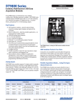
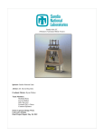
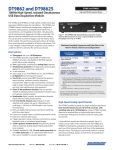
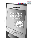
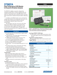
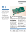
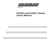
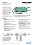
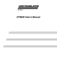
ECONseries ECONseries Low Cost USB Data Acquisition Modules Low Cost USB DAQ The ECONseries is a flexible yet economical series of multifunction data acquisition modules. You choose the number of analog I/O and digital I/O channels, the resolution you need, and the signal range of your application. Key Features: ■ ■ ■ ■ ■ ■ ■ ■ ■ ■ Ultimate flexibility with up to 24 analog inputs, 2 analog outputs, 28 digital I/O, and one 32-bit counter timer Independent subsystem operation at throughput rates up to 800 kHz per channel Simultaneous analog inputs on the DT9816 modules Signal range of ±10V on both the analog input and analog output, DT9812-2.5V has analog signal range of 0-2.44V Generate sine, rectangle, triangle, or DC waveforms with the analog outputs Up to 16-bit resolution for both the analog input and analog output subsystems Three versions of Digital I/O modules: isolated, nonisolated, and high current drive Monitor and control up to 28 digital I/O lines. Shielded, rugged enclosure with Phoenix connectors for noise immunity Easy signal connections on the DT9812-10V-OEM with two 20-pin connectors for all I/O signals Figure 1. The ECONseries provides economical, multifunction data acquisition instruments for the USB bus. Simply install the software, connect your module to any USB port, and measure. ■ ■ All modules run off USB power supply, no external power supply needed Perform event counting frequency measurement and continuous pulse output operations using the 16 or 32-bit counter-timer. Features Summary Module Subsystem DT9810 8 AI, 20 DIO, 1 C/T 8 AI, 2 AO, 16 DIO, 1 C/T DT9812-2.5V Independent Subsystem Operation @ Full Throughput Analog Input FSR Waveform Analog Output FSR External/ Internal Clocks & Triggers Power Fully Loaded 10-bits @ 25 kS/s aggregate Up to 25 kS/s 0 to 2.44 V — No/Yes USB <100 mA 12-bits @ 50 kS/s aggregate Up to 50 kS/s 0 to 2.44V, 1.22V, 0.61V, 0.305V, 0.1525V 0 to 2.44 V Yes/Yes USB <100 mA ±10V, 5V, 2.5V,1.25V ±10 V Resolution @ Throughput DT9812-10V DT9812-10V-OEM USB <175 mA DT9813-10V 16 AI, 2 AO, 8 DIO, 1 C/T 12-bits @ 50 kS/s aggregate Up to 50 kS/s ±10V, 5V, 2.5V,1.25V ±10 V Yes/Yes USB <175 mA DT9814-10V 24 AI, 2 AO, 1 C/T 12-bits @ 50 kS/s aggregate Up to 50 kS/s ±10V, 5V, 2.5V,1.25V ±10 V Yes/Yes USB <175 mA 6 SAI, 16 DIO, 1 C/T 16-bits @ 50 kS/s aggregate Up to 50 kS/s ±10V, ±5V — Yes/Yes USB <200mA DT9816-A 16-bits @ 150 kS/s aggregate Up to 150 kS/s DT9816-S 16-bits @ 800 kS/s aggregate Up to 800 kS/s — Yes — — — USB <500mA DT9816 DT9817 28 DIO, 1 C/T, Sink = 10mA, Source = 4.5 mA DT9817-H 28 DIO, 1 C/T, Sink = 64mA, Source = 15 mA DT9817-R Fully Isolated 16 DIO, 1 C/T; Switches up to ±30V @ 400 mA www.datatranslation.com US/Canada (800) 525-8528 Europe/Asia +49 (0) 7142-9531–0 Figure 2. Connect to a host computer using the standard USB 1.1 or 2.0 plug-in connector on the ECONseries module. The USB connector provides power to the module, eliminating the need for an external power supply, while providing complete enumeration for all data flow. Figure 3. Connect sensors directly to the screw terminal of the module. Screw terminals can accept AWG 26 to AWG 16 size wire. Easy to Hook-up Shielded, rugged enclosure provides noise immunity Standard USB Connector LED indicator provides USB status Built-in signal I/O screw terminal connectors Figure 4. ECONseries modules provide easy signal and USB connections in a shielded, rugged enclosure. www.datatranslation.com US/Canada (800) 525-8528 Europe/Asia +49 (0) 7142-9531–0 2 ECONseries Design Advantages Prevents Measurement Errors Operates Reliably Electro-Static Discharge ESD protection up to 8000V 4000V Touch and 8000V Gap ESD Protection Figure 5. The ECONseries provides 10 MOhms of input impedance for virtually error-free analog input measurements. Figure 6. The ECONseries provides 4000 V touch and 8000 V gap ESD protection circuitry for superior noise immunity. Performs Simultaneous Operations Figure 6. The ECONseries provides 4000 V touch and 8000 V gap ESD protection circuitry for superior noise immunity. Detects Edges for Pulse Width, Frequency, and Period Measurements Prevents Measurement Errors Built-in Waveform Generator for generating sine, ramp, triangle, square wave, and DC signals. Figure 8. The DT9812-2.5 V, DT9812-10V, DT9813-10V, and the DT9814-10V modules provide 2 waveform DACs for generating sine, ramp, triangle, square wave, and DC signals. www.datatranslation.com US/Canada (800) 525-8528 Figure 9. Programmable edges allow you to use the counter/ timer of an ECONseries module to measure the pulse width, frequency, and period of a signal. Europe/Asia +49 (0) 7142-9531–0 3 DT9816 Design Advantages Six Simultaneously Sampled Analog Inputs Ext Trig Ext Clk A/D Ch 0 T/H 16-Bit A/D A/D Ch 1 T/H 16-Bit A/D A/D Ch 2 T/H 16-Bit A/D A/D Ch 3 T/H 16-Bit A/D A/D Ch 4 T/H 16-Bit A/D A/D Ch 5 T/H 16-Bit A/D Accurate Measurements Designed In Data Stream Figure 10. The DT9816 modules feature six, independent, successive-approximation A/D converters with track-and-hold circuitry. Each converter uses a common clock and trigger for simultaneous sampling of all six analog input signals. The throughput rate varies depending on the model you choose. Figure 11. The A/D design of the DT9816 modules feature builtin accuracy. A maximum aperture delay of 35 ns (the time that it takes the A/D to switch from track to hold mode) is well matched at 5 ns across all six track-and-hold circuits, virtually eliminating the channel-to-channel skew that is associated with multiplexed inputs. A maximum aperture uncertainty of 1 ns (the jitter or variance in aperture delay), virtually eliminates phase noise in your data. Key Features of the DT9816: ■ High-Speed Simultaneous Acquisition – Acquire all six analog input channels simultaneously at up to 50 kHz per channel (DT9816), 150 kHz per channel (DT9816-A), or 800 kHz per channel (DT9816-S). ■ High-Resolution Data – 16-bit resolution for precision measurements. ■ Two Bipolar Input Ranges – Input range of ±10 V and ±5 V signal for maximum flexibility. ■ Digital I/O Functions – 8 fixed digital outputs for controlling external equipment. ■ Multifunction Counter/Timer – One 16-bit counter/ timer for event counting, frequency measurement, and continuous pulse output operations. Figure 12. This graph shows the outstanding quality of the DT9816-A for all error sources ... effective number of bits greater than 13.1 from all sources. Note the absence of harmonic content and digital switching noise across the full spectrum. www.datatranslation.com US/Canada (800) 525-8528 Europe/Asia +49 (0) 7142-9531–0 4 Analog Inputs Waveform Generation DT9814-10V provides 24 channels. The DT9816 modules provide 6 separate 16-bit analog converters for simultaneous acquisition of up to 6 single-ended analog inputs. The DT9812-2.5V module provides 2, 12-bit waveform analog output channels with an output signal range of 0 to 2.44V. The DT9812-10V, DT9813-10V, and DT9814-10V modules provide 2, 12-bit analog output channels with an output signal range of +/- 10V. These modules support an update rate of up to 50 kS/s. Generate sine, rectangle, triangle, or DC waveforms from one or both analog output channels. You can select the frequency, amplitude, duty, and offset cycle of the signal. The DT9810 provides 10-bit resolution, while the DT9812-2.5V, DT9812-10V, DT9813-10V, and the DT9814-10V provide 12-bit resolution. For maximum resolution, the DT9816 modules provide 16-bit resolution. DT9810 and DT9812-2.5V modules feature a full-scale input signal range of 0 to 2.44 V. If you need a full-scale input signal range of ±10 V, the DT9812-10V, DT9813-10V, DT9814-10V, DT9816, DT9816-A, and DT9816-S are available. The DT9816 modules also feature a full-scale input signal range of ± 5 V. The DT9812-2.5V provides gains of 1, 2, 4, 8, and 16; the DT9812-10V, DT9813-10V, and DT9814-10V provides programmable gains of 1, 2, 4, and 8; and the DT9816 modules provide gains of 1 and 2. Effective Input Ranges DT9812-2.5V DT9812-10V DT9813-10V DT9814-10V 1 0 to 2.44 V ±10V ±10V 2 0 to 1.22 V ±5 V ±5 V 4 0 to 0.61 V ± 2.5 V — 8 0 to 0.305 V ± 1.25 V — 0 to 0.1525 V — — Gain 16 DT9816 Throughput Before selecting a module, consider whether you need analog inputs, and if so, what kind of throughput you need. Modules with multiplexed inputs, such as the DT9810, DT98122.5V, DT9812-10V, DT9813-10V, and DT9814-10V provide only one A/D converter that is shared by the inputs. A multiplexer selects or switches the channel to acquire, which introduces a settling time and phase shift between channels. In a multiplexed architecture, the total or aggregate throughput is the maximum rate of the sampling clock. The DT9810 provides an aggregate throughput of up 25 kHz, while the DT98122.5V, DT9812-10V, DT9813-10V, and DT9814-10V provide an aggregate throughput of up to 50 kHz. The per channel rate is determined by dividing the maximum sampling rate by the number of inputs sampled. For example, if you are acquiring 8 inputs on a DT9812-10V, the per channel rate is 6.25 kS/s. Simultaneous analog input and analog output operations are supported at the driver level. Digital I/O Lines The DT9812-2.5V, DT9812-10V, DT9816, DT9816-A, and DT9816-S modules feature 8 digital input lines and 8 digital output lines. The DT9813-10V provides 4 digital input lines, and 4 digital output lines. The DT9810 module provides 20 programmable digital I/O lines. If you need more digital I/O lines and do not need analog I/O functionality, select the DT9817 or DT9817-H module, which provide 28 programmable digital I/O lines. The DT9817-H provides high drive capability with 15 mA source and 64 mA sink. Finally, the DT9817-R is a robust, isolated version with 16 digital I/O lines (8 in/8 out) that can switch up to +/- 30V@400 mA. The DT9817-H and DT9817-R are ideal for solid state or mechanical relays. Multifunction Counter/Timers The DT9816 modules support one 16-bit counter/timer channel. All other modules feature one 32-bit user counter/timer channel. You can perform event counting, frequency measurement, and continuous pulse output operations using this counter/timer. Programmable gates, clocks, and output signals are also supported at the driver level for maximum flexibility. In addition, programmable edges allow you to measure the time between two edges of a signal to determine the pulse width, frequency, or period of a signal. In contrast, modules that provide separate A/D converters per channel, such as the DT9816, DT9816-A, and DT9816-S, eliminate the phase shift between signals, allowing you to correlate simultaneous measurements of multiple inputs. The per channel sampling rate, in this case, is the maximum rate of the sampling clock (50 kS/s for the DT9816, 150 kS/s for the DT9816-A, and 800 kS/s for the DT9816-S). www.datatranslation.com US/Canada (800) 525-8528 Europe/Asia +49 (0) 7142-9531–0 5 Flexible Clocks and Triggers The DT9810, DT9812-2.5V, DT9812-10V, DT9813-10V, DT981410V, DT9816, DT9816-A, and DT9816-S modules support an internal trigger and internal clock. In addition, the DT98122.5V, DT9812-10V, DT9813-10V, DT9814-10V, DT9816, DT9816-A, and DT9816-S modules support an external trigger and clock. Use the internal trigger to start an analog input operation based on a software command, or use the external trigger to start an analog input operation based on an external event. Use the external clock signal to pace an analog input operation at a rate not available with the internal clock or when you want to pace at uneven intervals. Synchronizing Multiple Modules You can synchronize the analog input operations of multiple DT9812-2.5V, DT9812-10V, DT9813-10V, DT9814-10V, DT9816, DT9816-A, or DT9816-S modules by connecting the output of the counter/ timer from one module to the clock input of the next module as shown in Figure 13. Counter 0 Out Counter 0 Out Module #1 External Clock In Module #2 External Clock In Module #N External Clock In External Clock Source Figure 13. You can synchronize the analog I/O operations of multiple modules by connecting them together. Easy Signal Connections Screw terminals on the module allow easy and direct signal connections. No extra accessories are required! Simply wire your signals to the module and you’re all set. For OEM users, the board-only DT9812-10V-OEM provides two, 20-pin connectors to accommodate all I/O signals. And, because of the module’s high impedance, measurement errors are prevented. www.datatranslation.com US/Canada (800) 525-8528 Europe/Asia +49 (0) 7142-9531–0 6 Software Options Many software choices are available for application development, from ready-to-measure applications to programming environments. The following software is available for use with all USB modules and is provided on the Data Acquisition Omni CD: ■ ■ ■ ■ ■ ■ ■ ■ ■ Measure Foundry® – An evaluation version of this software is included on the Data Acquisition Omni CD. Measure Foundry® is a drag-and-drop test and measurement application builder designed to give top performance with ease-of-use development. Measurement Applets – Included in the Measure Foundry evaluation version. These small applications, developed with Measure Foundry, can be modified or combined to provide a specific solution. Order the full development version of Measure Foundry to develop applications using real hardware. quickDAQ application – An evaluation version of this .NET application is included on the Data Acquisition Omni CD. quickDAQ acquires analog data from all devices supported by DT-Open Layers for .NET software at high speed, plots it during acquisition, analyzes it, and/or saves it to disk for later analysis. Note: quickDAQ supports analog input functions only. DT9817 and DT9835 modules are DIO only and are not supported. Quick DataAcq application – The Quick DataAcq application provides a quick way to get up and running using an ECONseries module. Using this application, verify key features of the module, display data on the screen, and save data to disk. DT-Open Layers® for .NET Class Library – Use this class library if you want to use Visual C#® or Visual Basic® for .NET to develop application software for an ECONseries module using Visual Studio® 2003/2005/2008; the class library complies with the DT-Open Layers standard. DataAcq SDK – Use the Data Acq SDK to use Visual Studio 6.0 and Microsoft® C or C++ to develop application software for an ECONseries module using Windows®; the DataAcq SDK complies with the DT-Open Layers standard. DTx-EZ – DTx-EZ provides ActiveX® controls, which allows access to the capabilities of an ECONseries module using Microsoft Visual Basic or Visual C++®; DTx-EZ complies with the DT-Open Layers standard. DAQ Adaptor for MATLAB – Data Translation’s DAQ Adaptor provides an interface between the MATLAB® Data Acquisition (DAQ) toolbox from The MathWorks™ and Data Translation’s DT-Open Layers architecture. LV-Link – An evaluation version of this software is included on the Data Acquisition Omni CD. Use LV-Link to use the LabVIEW™ graphical programming language to access the capabilities of an ECONseries module. www.datatranslation.com US/Canada (800) 525-8528 The data recorder applet is developed with Measure Foundry and allows you to acquire data, plot it, and save it to disk. quickDAQ acquires analog data from all devices supported by DT-Open Layers for .NET software at high speed, plots it during acquisition, analyzes it, and/or saves it to disk for later analysis. Europe/Asia +49 (0) 7142-9531–0 7 Cross-Series Compatibility Ordering Information Virtually all Data Translation data acquisition boards, including the ECONseries, are compatible with the DT-Open Layers for .NET Class Library. This means that if your application was developed with one of Data Translation’s software products, you can easily upgrade to a new Data Translation board. Little or no programming is needed. User Manual Each data acquisition module includes a user’s manual that provides getting started and reference information. The manual is provided in electronic (PDF) format on the Data Acquisition Omni CD provided with the module. Technical Support Application engineers are available by phone and email during normal business hours to discuss your application requirements. Extensive product information, including drivers, example code, pinouts, a searchable Knowledge Base, and much more, is available 24 hours a day on our web site at www.datatranslation.com. For pricing and warranty information, please visit our website or contact your local reseller. Modules: ■ DT9810 ■ DT9812-2.5V ■ DT9812-10V ■ DT9812-10V-OEM ■ DT9813 -10V ■ DT9814 -10V ■ DT9816 ■ DT9816-A ■ DT9816-S ■ DT9817 ■ DT9817-H ■ DT9817-R Accessories: ■ DIN Mount Kit System Requirements: ■ Windows XP, Windows Vista, or Windows 7 ■ Available USB Port(s) (2.0 or 1.1) ■ CD-ROM drive Software Options: ■ Measure Foundry – Test and measurement application builder. SP1300-CD. ■ quickDAQ – High-performance, readyto-run application that lets you acquire, plot, analyze, and save data to disk at up to 2 MHz per channel. SP8501-CD ■ LV-Link – Access the power of Data Translation boards through LabVIEW. Free Software: ■ DAQ Adaptor for MATLAB – Access the analyzation and visualization tools of MATLAB. For more information about the ECONseries, please visit: http://www.datatranslation.com/info/ECONseries/ Copyright © 2010 Data Translation, Inc. All rights reserved. All trademarks are the property of their respective holders. Prices, availability, and specifications are subject to change without notice. www.datatranslation.com US/Canada (800) 525-8528 Europe/Asia +49 (0) 7142-9531–0