1
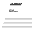
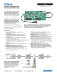
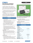
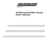
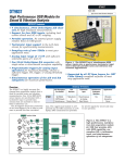
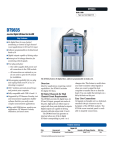
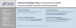
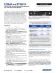
DT9826 Series DT9826 Portable, Simultaneous USB Data Acquisition Module USB Data Acquisition Module The DT9826 is a high-performance, multifunction data acquisition (DAQ) module for the USB bus. The DT9826 features 4, 8, or 16 simultaneous analog inputs, 16 digital input/output lines, 2 counter/timers, and a tachometer. All subsystems can be run synchronously. The DT9826 runs on USB power with sampling rates up to 41.6 kSamples/second, making it ideal for portable applications. Key Features: ■ ■ ■ ■ ■ ■ ■ ■ ■ ■ ■ ■ ■ ■ ■ Powered by USB... portable Simultaneous operation of analog input, digital I/O, counter/timer, and tachometer subsystems. 24-bit Sigma-Delta ADC per channel. 4, 8, or 16 single-ended, simultaneous analog input channels. Throughput rate up to 41.6 kSamples/second/channel Simultaneous operation of analog input, digital I/O, counter/timer, and tachometer subsystems at total throughput rates of over 830 kSamples/second. ±10V input range. Read the digital inputs, the two 32-bit counters, and one tachometer input using the A/D subsystem and the A/D clock to synchronize digital and analog measurements 8 digital input/8 digital output lines. Two 32-bit counter/timer (C/T) channels that perform event counting, up/down counting, frequency measurement, edge-to-edge measurement, continuous edge-to-edge measurement, continuous pulse output, one-shot, and repetitive one-shot operations. One 32-bit tachometer input channel. Read the value of the tachometer input in the analog input data stream, to measure the period or frequency of the tachometer synchronously with analog input measurements. Internal clock source. Software-programmable trigger source (software, external digital trigger, analog threshold trigger). ±500V galvanic isolation barrier that prevents ground loops to maximize analog signal integrity and protect your computer. Available either installed in a metal BNC connection box or as a board-level OEM version that can be installed in your own custom application. www.datatranslation.com US/Canada (800) 525-8528 Figure 1. Portable measurements can now be made with 4, 8, or 16 individual A/D channels. Each 24-bit sigma-delta A/D runs in parallel to prevent interference between channels. The DT9826 is fully featured with DIO, 32-bit C/Ts, tachometer, and multi-trigger modes. Software options abound to accommodate any environment. Available in BNC box or as embedded board-level OEM version. Analog Input Channels The DT9826 supports 4, 8, or 16 single-ended analog inputs. Each channel features its own 24-bit A/D converter, with sampling rates up to 41.6 kSamples/second. Using the DT9826 module, data can be acquired from a single analog input channel or from a group of analog input channels using the analog input channel list. Because these modules feature simultaneous sampling, the order of the channels in the channel list does not matter. The same channel cannot be specified more than once in the list. Using software, 20 entries can be entered in the channel list for sampling, including the analog input channels, digital input port, two 32-bit counter/timers, and the 32-bit tachometer input. This feature is particularly useful for correlating the timing of analog, digital, counter/timer, and tachometer events. When reading all input channels simultaneously, total throughput rates of up to 833 kSamples/second can be achieved. Europe/Asia +49 (0) 7142-9531–0 High Density, Simultaneous USB DT9826 is designed on an 8-layer board, using both the front and back, to provide superior performance under all conditions. Particular emphasis on the layout is critical to this performance DC-DC Converters provide internal analog voltages... Provide power to buffers Simultaneous Analog Inputs... 4, 8, or 16 Individual 24-bit sigma-delta A/D per channel Fully protected... ±500V galvanic isolation protects your PC and maintains signal integrity, breakdown gap in etch Ultra Digital I/O... 8 digital input lines & 8 digital output lines with flexibility for time stamping, pattern recognition, and synchronizing with external events Signal conditioning and ESD protection... Thin film resistors, capacitors, diode clamping provide scaling to high impedance buffers Full-featured Counter/ Timers... Two 32-bit C/T channels for counting events, up/ down, edge-to-edge, discrete or continuous, pulse output...ideal for testing apps Synchronous 32-bit tachometer input channel... Reads rotation values of period or frequency synchronously with analog input measurements Multi-trigger modes... Software, external, or analog threshold trigger available as trigger sources www.datatranslation.com Analog isolation barrier... Serial data from 16 A/D channels Flexible Power Connections... Portable operation for full specifications, optional +5V connection for secondary use when desired US/Canada (800) 525-8528 Europe/Asia +49 (0) 7142-9531–0 High-Speed USB 2.0... USB 2.0 connector for data transfer at 480Mbps, optional pin substitute for embedded OEM use 2 Ext. ADC Trigger 24-Bit ADC Analog Input 0 . . . 24-Bit ADC Analog Input 15 16 Simultaneous A/D Channels 500V Isolation Barrier Threshold Trigger Detect (Any ADC Channel) . . . Tach Input Tachometer UserClock[1:0] UserClock[1:0] UserGate[1:0] UserGate[1:0] UserOut[1:0] UserOut[1:0] DigitalIn[7:0] DigitalOut[7:0] Input FIFO Control & Trigger Logic USB Interface USB 2 x 32-bit Up/Down Counter/ Timers 8-bit Digital In 8-bit Digital Out Figure 2. DT9826 Block Diagram. 500mA max output level Startup in-rush current being sequenced www.datatranslation.com Figure 3. USB module portability requires in-rush current to always be below 500mA , allowing 50 micro Columbs spike for short duration. Exceeding this level can shut down the port. The DT9826 sequences the internal power supplies to keep this current under the maximum allowed to guarantee pristine measurements. The left side of graph shows the current ramping up as the internal power supplies are sequenced in order to keep the inrush current under 500mA. The right side shows a very slight increase to 450mA when the clock frequency is increased from 20KHz to 40KHz. Max throughput of 40kHz US/Canada (800) 525-8528 Europe/Asia +49 (0) 7142-9531–0 3 Making Dynamic Measurements (FIGURES 4a-4f) The FFT plots show the dynamic performance of the DT9826. Many users believe that a 24-bit A/D system will give 24 bit accuracy or at least close to that accuracy. But when measuring a dynamic signal, i.e. with frequency components above DC, other factors degrade the measurement in attaining that 24 bit accuracy. Noise and harmonic distortion are key factors to degrading accuracy. Also phase shift becomes an issue at low bandwidths. But it isn’t just the circuitry. Layout of the critical circuit etch, spacing between noise-generating and noise-sensitive devices as well as analog and digital etch patterns, and thermal effects from one circuit to another are all culprits in degrading accuracy. Therefore, DC specifications are useful, and plots in Fig 4(a) and 4(b) yield the best ENOB figures of merit at 16 bit accuracy from all errors at operating throughputs of 40kHz and 20kHz. But this is with zero signal level. But dynamic FFT plots at higher input voltage, and maximum operating frequency give the best indicator of accuracy. Fig 4(c) and 4(d) show results at ½ full scale (-6dB) and yield good results at approximately 15 bits ENOB (Effective Number if Bits) performance. Now worst case is Fig 4(e) and 4(f) showing maximum signal level of ±10V and sample rates of 40kHz and 20kHz. The ENOB plot shows 14.3, rather than the full 24-bit accuracy. This number is actually outstanding and has been attained through careful design with many years of experience. So conditions of use really determine the accuracy for dynamic measurements. The ENOB number can be higher (Fig 4a-d) if less than full scale is used (e.g. ½ scale), but this would give a misleading picture for many users. Download the ENOB white paper: http://www.datatranslation.com/ENOBPAPER/ www.datatranslation.com US/Canada (800) 525-8528 Europe/Asia +49 (0) 7142-9531–0 4 Figure 4(a). 0V input, 40kHz sampling rate. Figure 4(b). 0V input, 20kHz sampling rate. Figure 4(c). 1/2 full scale, 40kHz sampling rate. Figure 4(d). 1/2 full scale, 20kHz sampling rate. www.datatranslation.com US/Canada (800) 525-8528 Europe/Asia +49 (0) 7142-9531–0 5 Figure 4(e). Full scale, 40kHz sampling rate. Figure 4(f). Full scale, 20kHz sampling rate. Input Sample Clock Sources Analog Input Conversion Modes The DT9826 module provides an internal A/D clock source for pacing analog input operations. Using software, specify the clock source as internal and the clock frequency at which to pace the operation. The minimum clock frequency is 10Hz. DT9826 supports a maximum clock frequency of 41.6kHz. All input channels are clocked simultaneously at the specified rate. The DT9826 module supports the following conversion modes: Notes: According to sampling theory (Nyquist Theorem), a frequency that is at least twice as fast as the input’s highest frequency component should be specified. For example, to accurately sample a 10kHz signal, a sampling frequency of at least 20kHz. should be used. Doing so avoids an error condition called aliasing, in which high frequency input components erroneously appear as lower frequencies after sampling. The input sample clock also paces the acquisition of the digital input port, counter/timers, and tachometer if specified in the analog input channel list. www.datatranslation.com US/Canada (800) 525-8528 ■ ■ Single-Value Mode Continuous Scan Mode Single-Value Mode Single value operations are the simplest to use. The analog input channel to sample is specified in software. The module acquires the data from the specified channel and returns the data immediately. For a single-value operation, a clock source, trigger source, scan mode, or buffer cannot be specified. Single-value operations stop automatically when finished. Continuous Scan Mode Continuous scan mode takes full advantage of the capabilities of the DT9826 module. Use continuous scan mode to accurately control the period between successive simultaneous conversions of all channels in a channel list. Using software, the channel list, clock source, trigger source, scan mode, and buffer are specified. Europe/Asia +49 (0) 7142-9531–0 6 When it detects the start trigger, the module simultaneously acquires pre-trigger data from all of the input channels, including the digital inputs, counter/timers, and tachometer input, and converts the data from the analog input channels. If the channel is included in the channel list, the sampled data is placed in the allocated buffer(s). When the reference trigger occurs, pre-trigger acquisition stops and post-trigger acquisition starts. The operation continues until the number of samples you specify for the post-trigger scan count are acquired; at that point, the operation stops. The conversion rate is determined by the frequency of the input sample clock. The sample rate, which is the rate at which a single entry in the channel list is sampled, is the same as the conversion rate due to the simultaneous nature of the module. Input Triggers A trigger is an event that occurs based on a specified set of conditions. On the DT9826, a start trigger and reference trigger can be specified. Pre-trigger acquisition starts when the module detects the start trigger event. When the reference trigger occurs, pre-trigger acquisition stops. The DT9826 module supports the following trigger sources: ■ ■ ■ Software trigger (for the start trigger) – A software trigger event occurs when the analog input operation is started (the computer issues a write to the module to begin conversions). Using software, the trigger source is specified as a software trigger. External digital (TTL) trigger (for the start trigger) – An external digital (TTL) trigger event occurs when the DT9826 module detects either a rising-edge (positive) or falling-edge (negative) transition on the signal connected to the AD Trig connector on the module. Using software, the trigger source is specified as an external, positive digital (TTL) trigger or an external, negative digital (TTL) trigger. Analog threshold trigger (for the start and reference trigger) – An analog threshold trigger event occurs when the signal on a specified analog input channel rises above or falls below a programmable threshold level. Using software, the following parameters are specified: start trigger source, any one of the analog input channels as the threshold input channel, and a threshold level between ±10 V. Data Transfer Before acquisition begins, buffers must be allocated to hold the data. An event is raised whenever a buffer is filled allowing data to be moved and/or processed as needed. Data is written to multiple allocated input buffers continuously; when no more empty buffers are available, the operation stops. The data is gap-free. www.datatranslation.com US/Canada (800) 525-8528 Tachometer Input Features The DT9826 module supports a tachometer signal with a range of ±30V. This signal has a maximum frequency of 1 MHz and minimum pulse width of 0.4µs. The threshold voltage is fixed at +2V with 0.5V of hysteresis. The frequency or period of the tachometer input signal can be measured to calculate the rotation speed for high-level (±30V) tachometer input signals. An internal 12 MHz counter is used for the measurement yielding a resolution of 83 ns (1/12MHz). The number of counts between two consecutive starting edges of the tachometer input signal can be read by including channel 16 in the analog input channel list. The starting edge is programmable (either rising or falling). The software automatically synchronizes the value of the tachometer input with the analog input measurements, so that all measurements are correlated in time. The tachometer input is treated like any other channel in the analog input channel list; therefore, all the triggering and conversion modes supported for analog input channels are supported for the tachometer input. Digital I/O Lines DT9826 modules support one digital input port, consisting of 8 digital input lines, and one digital output port, consisting of 8 digital output lines. The resolution is fixed at 8-bits. A digital line is high if its value is 1; a digital line is low if its value is 0. On power up or reset, a low value (0) is output from each of the digital output lines. The DT9826 module supports the following digital I/O operation modes: ■ ■ Single-value operations are the simplest to use but offer the least flexibility and efficiency. The digital I/O port is specified. Data is then read from or written to all the digital I/O lines. For a single-value operation, a clock or trigger source cannot be specified. Single-value operations stop automatically when finished. Continuous digital input takes full advantage of the capabilities of the DT9826 module. The digital input port (all 8 digital input lines) is specified as channel 19 in the analog input channel list. A clock source, scan mode, trigger source, buffer, and buffer wrap mode for the digital input operation can be specified. The input sample clock (internal or external) paces the reading of the digital input port (as well as the acquisition of the analog input and counter/timer channels). Europe/Asia +49 (0) 7142-9531–0 7 Counter/Timer Channels ■ The DT9826 modules provide two 32-bit counter/timers. Each counter accepts a clock input signal and gate input signal and outputs a pulse (pulse output signal). Using software, one or both of the counter/timers can be specified in the analog input channel list (as channels 17 and 18). Counter/Timer Operation Modes DT9826 modules support numerous counter/timer operation modes, including event counting, up/down counting, frequency measurement, edge-to-edge measurement, continuous edge-to-edge measurement, rate generation, oneshot, and repetitive one-shot. Counter/Timer Clock Sources The following clock sources are available for the counter/ timers: ■ ■ Internal C/T clock – The internal C/T clock always uses an 48 MHz time base. Through software, specify the clock source as internal, and specify the frequency at which to pace the operation (this is the frequency of the Counter n Out signal). External C/T clock – An external C/T clock is useful to pace counter/timer operations at rates not available with the internal C/T clock or to pace at uneven intervals. The frequency of the external C/T clock can range from 0.011176Hz to 24MHz. Counter/timer operations start on the rising edge of the clock input signal. A clock divider between 2 and 4,294,967,296 is supported. Gate Types The edge or level of the Counter n Gate signal determines when a counter/timer operation is enabled. The DT9826 module supports the following gate types: ■ ■ ■ ■ None – A software command enables any counter/timer operation immediately after execution. Logic-low level external gate input – Enables a counter/ timer operation when the gate signal is low, and disables the counter/timer operation when the gate signal is high. Note that this gate type is used for event counting and rate generation modes. Logic-high level external gate input – Enables a counter/ timer operation when the gate signal is high, and disables a counter/timer operation when the gate signal is low. Note that this gate type is used for event counting and rate generation modes. Falling-edge external gate input – Enables a counter/ timer operation when a high-to-low transition is detected on the gate signal. In software, this is called a low-edge gate type. Note that this gate type is used for edge-toedge measurement, one-shot, and repetitive one-shot mode. www.datatranslation.com US/Canada (800) 525-8528 Rising-edge external gate input – Enables a counter/timer operation when a low-to-high transition is detected on the gate signal. In software, this is called a high-edge gate type. Note that this gate type is used for edge-to-edge measurement, one-shot, and repetitive one-shot mode. Pulse Output Types and Duty Cycles The DT9826 modules can output the following types of pulses from each counter/timer: ■ ■ High-to-low transitions – The low portion of the total pulse output period is the active portion of the counter/ timer clock output signal. Low-to-high transitions – The high portion of the total pulse output period is the active portion of the counter/ timer pulse output signal. The pulse output type is specified in software. The duty cycle (or pulse width) indicates the percentage of the total pulse output period that is active. For example, a duty cycle of 50 indicates that half of the total pulse output is low and half of the total pulse output is high. The duty cycle is specified in software. USB 2.0 Compatibility The DT9826 module is fully compatible with USB 2.0 and USB 1.1. USB 2.0 extends the speed of connection to up to 480Mbps. For optimal performance, it is recommended that the DT9826 module be used with a USB 2.0 port. The DT9826 can be used with a USB 1.1 port, but at USB 1.1 performance. The DT9826 is a complete high speed, 24-bit data acquisition system that runs on USB power. ±500V Galvanic Isolation Protects Your Data Computers are susceptible to ground-spikes through any external port. These spikes can cause system crashes and may even cause permanent damage to the computer. The DT9826 module features ±500 Volts of galvanic isolation to protect the computer from ground-spikes and to ensure a reliable stream of data. Documentation The DT9826 module includes a user’s manual that provides getting started and reference information about using the DT9826. The manual is provided in electronic (PDF) format on the Data Acquisition Omni CD provided with the module. Technical Support Application engineers are available by phone and email during normal business hours to discuss your application requirements. Extensive product information, including drivers, example code, pinouts, a searchable Knowledge Base, and much more, is available 24 hours a day on our web site at www.datatranslation.com. Europe/Asia +49 (0) 7142-9531–0 8 Software Options Many software choices are available for application development, from ready-to-measure applications to programming environments, and run under Microsoft® Windows®XP/Vista/7. The following software is available for use with this USB DAQ module, and is provided on the Data Acquisition Omni CD: ■ ■ ■ ■ ■ ■ ■ ■ Device Driver – The device driver allows the use of this USB DAQ module with any of the supported software packages or utilities. quickDAQ application – An evaluation version of this .NET application is included on the Data Acquisition Omni CD. quickDAQ acquires analog data from all devices supported by DT-Open Layers for .NET software at high speed, plots it during acquisition, analyzes it, and/or saves it to disk for later analysis. Note: quickDAQ supports analog input functions only. Quick DataAcq application – The Quick DataAcq application provides a quick way to get up and running using your DAQ module. Using this application, verify key features of the module, display data on the screen, and save data to disk. DT-Open Layers® for .NET Class Library – Use this class library if you want to use Visual C#® or Visual Basic® for .NET to develop application software for your USB module using Visual Studio® 2003/2005/2008; the class library complies with the DT-Open Layers standard. DataAcq SDK – Use the Data Acq SDK to use Visual Studio 6.0 and Microsoft® C or C++ to develop application software for your module using Windows®; the DataAcq SDK complies with the DT-Open Layers standard. DTx-EZ – DTx-EZ provides ActiveX® controls, which allows access to the capabilities of your module using Microsoft Visual Basic or Visual C++®; DTx-EZ complies with the DTOpen Layers standard. DAQ Adaptor for MATLAB – Data Translation’s DAQ Adaptor provides an interface between the MATLAB® Data Acquisition (DAQ) toolbox from The MathWorks™ and Data Translation’s DT-Open Layers architecture. LV-Link – Data Translation’s LV-Link is a library of VIs that enable LabVIEW™ programmers to access the data acquisition features of DT-Open Layers compliant USB and PCI devices. www.datatranslation.com US/Canada (800) 525-8528 Figure 7. quickDAQ acquires analog data from all devices supported by DT-Open Layers for .NET software at high speed, plots it during acquisition, analyzes it, and/or saves it to disk for later analysis. Europe/Asia +49 (0) 7142-9531–0 9 Accessories Ordering Information The following optional accessories are available for use with the DT9826 module: ■ ■ ■ ■ ■ ■ EP353 – Accessory panel. Provides one 37-pin connector and one 26-pin connector for attaching analog input signals. Used with the STP37 and EP360. (For OEM configurations only.) EP355 – This screw terminal panel provides a 14-position screw terminal block for attaching analog input, digital I/O, counter/timer, and clock signals. (For OEM configurations only.) EP356 – This accessory panel provides two 37-pin, D-sub connectors for attaching analog ouput, digital I/O, counter/timer, tachometer, and trigger signals. Used with the STP37 and EP333. (For OEM configurations only.) STP37 – This screw terminal panel allows connections to analog input, digital I/O, counter/timer, tachometer, and trigger signals from the EP353 or EP356 accessory panel. (Can be used with -BNC and -OEM versions.) EP333 – 2-meter shielded cable with two 37-pin connectors that connect an EP356 accessory panel to an STP37 screw terminal panel. (Can be used with the -BNC and -OEM versions for DIO and C/T connections.) EP360 - 2-meter shielded cable with two 37-pin connectors that connect an EP353 accessory panel to an STP37 screw terminal panel. (Can be used with the -BNC and -OEM versions for analog input connections.) EP353 STP37 EP356 EP333 Figure 8. The EP333 cable, along Figure 9. This example shows an EP353 accessory with the STP37, allow screw terminal panel, which plugs into connector J2, and an EP356 connections to the EP356 (shown accessory panel, which plugs into J3. below). Figure 10. With the optional DIN rail mounting kit (BNC-DIN-RAIL-KIT), you can mount the DT9826 BNC model to a standard DIN rail. All Data Translation hardware products are covered by a 1-year warranty. For pricing information, please visit our website or contact your local reseller. Hardware ■ DT9826 ■ DT9826-OEM ■ DT9826-4 ■ DT9826-4-OEM ■ DT9826-8 ■ DT9826-8-OEM Accessories ■ BNC DIN Rail Kit – Kit for mounting USB modules in BNC enclosure to a DIN rail. Includes mounting clips, screws, and instructions. DIN Rail not included. ■ EP333 – 2-meter shielded cable for the EP356 and STP37 ■ EP353 – Accessory panel with one 37pin connector and one 27-pin connector ■ EP355 – Screw terminal panel ■ EP356 – Accessory panel with two 37pin, D-sub connectors ■ EP360 – 2-meter shielded cable for the EP353 and STP37 ■ STP37 – Screw terminal panel Software The following software is available for purchase separately: ■ quickDAQ (SP8501-CD) – Highperformance, ready-to-run application that lets you acquire, plot, analyze, and save data to disk at up to 2 MHz per channel. Free Software Downloads The following software is available for free download from our website: ■ DAQ Adaptor for MATLAB – Access the analyzation and visualization tools of MATLAB®. ■ LV-Link – Access the power of Data Translation boards through LabVIEW™. For more information about the DT9826, including specifications, please visit: http://www.datatranslation.com/info/DT9826/ Copyright © 2012 Data Translation, Inc. All rights reserved. All trademarks are the property of their respective holders. Prices, availability, and specifications are subject to change without notice. www.datatranslation.com US/Canada (800) 525-8528 Europe/Asia +49 (0) 7142-9531–0