1
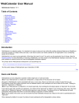
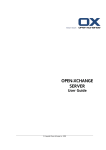
®
Digital Signage
Creator
Digital Signage Creator
Hardware Manual
www.gefen.com
ASKING FOR ASSISTANCE
Technical Support:
Telephone
Fax
(818) 772-9100
(800) 545-6900
(818) 772-9120
Technical Support Hours:
8:00 AM to 5:00 PM PST Monday thru Friday PST
Write To:
Gefen, LLC
c/o Customer Service
20600 Nordhoff St
Chatsworth, CA 91311
www.gefen.com
[email protected]
Notice
Gefen, LLC reserves the right to make changes in the hardware, packaging, and
any accompanying documentation without prior written notice.
Digital Signage Creator is a trademark of Gefen, LLC
© 2012 Gefen, LLC. All rights reserved.
All trademarks are the property of their respective owners.
Rev A8
CONTENTS
1
Introduction
2
Operation Notes
3
Features
4
Panel Layout
5
Panel Descriptions
6
Connecting And Operating The Digital Signage Creator
6
How to Connect the Digital Signage Creator
7
Accessing the Digital Signage Creator HTTP Server
8
Using the Digital Signage Creator Web Interface
25
DHCP Configuration
26
Static IP Configuration
30
Configuring a USB Drive with the Digital Signage Creator
32
Configuring Network Credentials for Remote Servers
34
Administering User Rights
49
Connecting to the Digital Signage Creator (Mac OS X)
50
Using the Digital Signage Creator HTTP Server
52
Content Access Modes
53
Configuring the RS-232 Serial Interface
53
Resetting to the Factory Default Settings
55
Specifications
57
Warranty
INTRODUCTION
Congratulations on your purchase of the Digital Signage Creator. Your complete
satisfaction is very important to us.
Gefen
Gefen delivers innovative, progressive computer and electronics add-on solutions
that harness integration, extension, distribution and conversion technologies.
Gefen’s reliable, plug-and-play products supplement cross-platform computer
systems, professional audio/video environments and HDTV systems of all sizes
with hard-working solutions that are easy to implement and simple to operate.
The Gefen Digital Signage Creator
The Gefen Digital Signage Creator (Digital Signage Creator) enriches digital
signage projects with high quality video, audio, images, animations and text.
All these media types can be retrieved by Digital Signage Creator from local or
network resources and can be combined and rendered on any type of digital
displays following specific graphical layouts and time schedules.
Digital Signage Creator extends the basic functionalities of state of the art media
players supporting Hyper Media content. The term hypermedia is used as a
logical extension of the term hypertext, in which graphics, audio, video, plain text
and hyperlinks intertwine to create a generally non-linear medium of information.
Digital Signage Creator brings hypermedia content to digital displays in several
ways.
How It Works
The Gefen Digital Signage Creator simplifies the publishing and maintenance of
your digital signage project.
Connected to digital displays through HDMI and VGA, Digital Signage Creator is
capable of rendering combinations of media elements from a rich set of formats:
audio, video, vector graphics, pictures and text. Digital Signage Creator natively
implements the open standards required to schedule, update, stream, and
animate each supported media. Distributing content from a central location onto
a specific display is as easy as publishing a Web page.
As a network device, Digital Signage Creator offers plug-and-play functionalities
that simplify installation, remote maintenance and monitoring. From anywhere,
your network of digital displays is under control.
1
OPERATION NOTES
READ THESE NOTES BEFORE INSTALLING OR
OPERATING THE DIGITAL SIGNAGE CREATOR
•
This manual covers operation of the Digital Signage Creator hardware.
Please see the Digital Signage Director manual for software operation.
•
The Digital Signage Creator uses DHCP by default. The unit is always
reachable at http://gef-dsc-xxxxxxxxxxxx.local from Zeroconf enabled
computers on the local network. Replace “x” with the MAC address of the
unit (without the colons). This is located on a sticker underneath the unit.
2
FEATURES
Features
•
Standard and simplified way to schedule and display digital signage video
and audio with low operational costs
•
User-friendly content creation software has built-in layout templates to get
you up and running quickly
•
Individual content playback can have multiple time, day, and month settings
•
Small size of the DSC product makes for easy installation
•
Supports horizontal and vertical displays, direct iCal sync, local and remote
publishing
•
1.5 GB internal flash memory plus USB 2.0 port for expansion via USB flash
drive or HDD
•
Simultaneously active HDMI and VGA ports, L/R analog audio output
•
Natively supports multiple Web-streaming formats including RSS and ASX
•
Supported Video Codecs: MPEG-1, MPEG-2, H264, MPEG-4 (Part 2),
Microsoft VC1 (Windows Media 9) and MJPEG.
•
Supported Audio Codecs : AAC (HE-AAC, AAC LC), MPEG1/2 Layer 3
(“MP3”), PCM, G.726 and G.711
•
Supported Media File Containers: AVI, ASF/WMV, VOB, MP4, MOV, MP3,
WAV, and MP4/M4A
•
Streaming media protocol: MMS, RTSP, RTP, SDP, HTTP; Unicast and
multicast
•
Scripting languages: PHP5, JavaScript
•
Import filters provided: Flash 9, Microsoft PowerPoint, BMP, TIFF, XPM,
WBMP, PNM bitmap
•
Still image formats: JPEG, PNG, GIF, SVG
•
Serial RS-232 port for two way control of external devices
Package Includes
(1) Digital Signage Creator
(1) 5V DC Locking Power Supply
(1) 6 ft Locking HDMI Cable (M-M)
(1) Quick-Start Guide
3
PANEL LAYOUT
Front Panel
1
2
3
4
Back Panel
6
7
8
4
9
5
PANEL DESCRIPTIONS
1
Mini-Plug to RS-232 Serial Port
This port is used to control functions and features using serial communications.
2
Ethernet Port
Connects the Digital Signage Creator to the network using Ethernet cabling.
When connected, the Digital Signage Creator unit can be controlled using the
built-in Web interface of the DSD (Digital Signage Director) software.
3
USB Port
Connect a USB cable to this port. This port supports USB 2.0 (up to 10
Mbps) and can be used to connect external storage devices and touchscreen
controllers.
4
Status Indicator
This LED will flash bright green when the Digital Signage Creator is operating
normally. If the Digital Signage Creator encounters an error, the LED will flash
red or orange.
5
Reset Button
Press and hold this button for about five seconds to reboot the Digital Signage
Creator unit.
6
5V DC Locking Power Connector
Connect the included 5V DC locking power supply to this connector.
7
HDMI Output
Connect an HDTV display to this HDMI port.
8
3.5mm L/R Analog Stereo mini-jack Output
This port is used to connect an external audio amplifier/device. This port will
accept a standard 3.5 mm analog stereo connector.
9
VGA Output
Connect a VGA display to this port.
5
CONNECTING AND OPERATING
THE DIGITAL SIGNAGE CREATOR
How to Connect the Digital Signage Creator
1.
Connect an HDTV display to the output port on the rear panel of the Digital
Signage Creator using the included 6 foot HDMI cable.
NOTE: A VGA monitor can also be connected to the Digital Signage Creator.
The HDMI and VGA ports are active at all times.
2.
Connect an amplified speaker or audio device to the 3.5mm L/R analog
stereo output for external audio support.
3.
Optionally connect a 3.5mm to DB-9 serial cable to the 3.5mm mini-plug
serial port. This port is used to control the Digital Signage Creator using
RS-232.
4.
Connects the Digital Signage Creator to the network using Ethernet cabling.
NOTE: If the Digital Signage Creator is connected directly to the PC, a
crossover cable must be used.
5.
Connect the 5V locking power supply to the Digital Signage Creator. Do not
overtighten the locking connector. Plug the power supply into an available
wall outlet. The Status Indicator on the front of the unit will begin flashing
bright green indicating that the Digital Signage Creator is powered.
Wiring Diagram for the Digital Signage Creator
HDMI CABLE
VGA CABLE
ETHERNET CABLE
®
Router
USB Flash Drive*
Gefen Digital
Signage Creator
Using HDMI
*USB Device, used for additional storage, is optional
Using VGA
6
EXT-DSC
CONNECTING AND OPERATING
THE DIGITAL SIGNAGE CREATOR
Accessing the Digital Signage Creator HTTP Server (PC)
This procedure is required to access the Digital Signage Creator for the first time,
administer the HTTP server, or to publish content on a Digital Signage Creator
unit.
Use this procedure only if the default network configuration has not
been modified. See Resetting the Digital Signage Creator to the Factory
Default Settings on page 53 to make sure that the Digital Signage
Creator has the default network configuration.
1.
Connect the PC to the Digital Signage Creator according to the instructions
on page 6.
2.
Configure the network on the PC.
•
The PC must be assigned a static IP address by the Network Administrator.
This address must be on the same subnet as the Digital Signage Creator
unit.
•
An IP address automatically assigned by a DHCP server located on the
same network as the Digital Signage Creator unit.
3.
Once the PC has been configured, verify the following:
•
The Digital Signage Creator has completed the boot process (allow about
one minute after the Digital Signage Creator has been powered). If the
Digital Signage Creator is connected to an HDTV display, the default screen
should be displayed.
•
Check that the LED on the front panel of the Digital Signage Creator is
flashing bright green.
•
Open a Web browser and enter the following address:
http://gef-dsc-[MAC address].local
Do not include the colons when entering the MAC address.
Example: http://gef-dsc-01c91011132.local
6.
The browser will connect to the Digital Signage Creator HTTP Server and
display the screen shown on the following page:
7
CONNECTING AND OPERATING
THE DIGITAL SIGNAGE CREATOR
Using the Digital Signage Creator Web Interface
The Web Interface is divided into two sections:
•
Information
•
Administration
Information > Status
The Status function returns the status screen which is displayed once the Web
interface is launched.
8
CONNECTING AND OPERATING
THE DIGITAL SIGNAGE CREATOR
Information > Snapshot
The Snapshot function creates a snapshot of the current content shown on the
display and displays the image in the Snapshot window.
Click the Refresh button to capture the current content displayed on the screen.
The captured image is stored as a .PHP file. Clicking in the Snapshot window
will display the full-size image in the web browser.
The full path to the snapshot will be displayed in the address bar (e.g. http://
gef-dsc-[DSC SERIAL NUMBER]/snapshot/snapshot.php)
9
CONNECTING AND OPERATING
THE DIGITAL SIGNAGE CREATOR
Information > Display Info
Shows information about the display connected to the Digital Signage Creator.
The Digital Signage Creator gets this information by reading the EDID of the
attached display.
10
CONNECTING AND OPERATING
THE DIGITAL SIGNAGE CREATOR
Information > Storage
Provides information about the storage media used by the Digital Signage Creator. A link to the Local Storage is also provided. Clicking on this link will display
the directories and content on the Digital Signage Creator.
Clicking on the Local Storage Access link (Server Address) will display a Web
page similar to the following:
11
CONNECTING AND OPERATING
THE DIGITAL SIGNAGE CREATOR
The file list can be sorted by clicking on Name, Last Modified, Size, or
Description.
Information > Logs
Allows viewing of all Resource, JavaScript, Information, and Warning logs which
have been generated by the Digital Signage Creator.
12
CONNECTING AND OPERATING
THE DIGITAL SIGNAGE CREATOR
Administration > Display Settings > Basic
Allows the resolution, orientation, and other display options to be changed. The
Digital Signage Creator contains seven predefined video modes for computer
monitors and HD displays.
1
Select the output resolution to activate. For more detailed settings, see
Administration > Advanced > Display Settings.
The aspect ratio of the connected display will be automatically updated
according to the selected resolution. The aspect ratio can be set
manually by placing a check mark in the Force Aspect Ratio check box
and then selecting the aspect ratio (see page 15).
2.
Select the display orientation. If the display connected to the Digital Signage
Creator is rotated vertically, make sure to use the correct rotation direction.
3.
If audio is being used, place a check the Enable audio output check box.
13
CONNECTING AND OPERATING
THE DIGITAL SIGNAGE CREATOR
A preview of the current display settings are shown on the Display Settings page.
Click the Apply button to save the changes and reboot the Digital Signage Creator.
Display Settings > TV Screen
Sets the output resolution for the HDMI output: 480p or 720p
Display Settings > Computer Monitor
Sets the output resolution for the computer monitor. Select VGA, SVGA, or XGA.
Display Settings > Wide Computer Monitor
Sets the computer monitor output to wide format. Select WVGA or WSVGA.
14
CONNECTING AND OPERATING
THE DIGITAL SIGNAGE CREATOR
Display Settings > Force Aspect Ratio To
Check this box to force the aspect ratio on the output. Select 4:3 (pan-and-scan)
or 16:9 or 16:10 (widescreen).
Display Settings > Screen Orientation
Use the pull-down list box to select: Horizontal, Rotate 90 Right, Rotate 90 Left,
Rotate 180, Flip Vertical, or Flip Horizontal.
Display Settings > Overscan Percentage
This function compensates for the display overscan. Select between 0 - 5. A
lower setting ______________. A higher setting ________________.
Display Settings > Enable Audio Output
Enables the audio output on the Digital Signage Creator.
15
CONNECTING AND OPERATING
THE DIGITAL SIGNAGE CREATOR
Display Settings > Power Mode for VGA Output
Controls the voltage level of pin 9 on the VGA connector.
Setting
Description
Automatic
Turns off VGA monitor when disconnected
Always On
VGA monitor is always on when connected
Always Off
Turns off the VGA monitor
Display Power Save > Enable Display Power Saving
Allows the connected display to be turned off and turned on ___________
Check the box to enable this feature.
Display Power Save > Use Fixed Schedule for Display Power
Check this box to enter specific times as to when the display should be turned
off and turned on. Enter the times in the Turn Monitor ON and Turn Monitor
OFF text boxes. NOTE: This feature can only be used when the Enable Display
Power Saving option is enabled (see page 18).
16
CONNECTING AND OPERATING
THE DIGITAL SIGNAGE CREATOR
Administration > Display Settings > Advanced
Allows advanced control of resolution and other display options.
After changing the Display Settings, click the Check button to test the video
settings.
Advanced > Display Settings > Resolution
Select the output resolution from the pull-down list box.
The list of available resolutions can be found on the next page.
17
CONNECTING AND OPERATING
THE DIGITAL SIGNAGE CREATOR
Available resolutions:
Resolution
VGA
ED
HD
640 x 480
720 x 480
720 x 576
800 x 500
800 x 600
1024 x 640
1024 x 768
1280 x 720
1280 x 800
1920 x 1080
Advanced > Display Settings > Default Aspect Ratio
Select the default aspect ratio on the output from the pull-down list box.
Default Aspect Ratio
4:3
16:9
16:10
Advanced > Display Settings > Force Standard Video Modes
Check this box to force standard video modes.
18
CONNECTING AND OPERATING
THE DIGITAL SIGNAGE CREATOR
Advanced > Display Settings > Restrict Video Mode To
Restricts the video mode.
Video Mode
HDMI
VESA
GTF
VESA, GTF
HDMI, GTF
HDMI, VESA
Advanced > Display Settings > Power Mode for VGA Output
Sets the power mode when connecting to a VGA monitor.
Power Mode
Automatic
Always On
Always Off
Advanced > Display Settings > HDMI Display Supports Underscan
Check this box is the HDMI display supports underscan.
19
CONNECTING AND OPERATING
THE DIGITAL SIGNAGE CREATOR
Advanced > Display Settings > Overscan Percentage
Adjusts the amount of overscan on the display.
Overscan Percentage
0
1
2
3
4
5
Advanced > Display Settings > Force Vertical Refresh
Forces the vertical refresh rate.
Refresh Rate
24 Hz
25 Hz
30 Hz
50 Hz
60 Hz
20
CONNECTING AND OPERATING
THE DIGITAL SIGNAGE CREATOR
Advanced > Display Settings > Screen Orientation
Sets the Screen Orientation.
Screen Orientation
Horizontal
Rotate 90 Right
Rotate 90 Left
Rotate 180
Flip Vertical
Flip Horizontal
Advanced > Display Settings > Enable Audio Output
Check this box to enables the audio output on the 3.5mm stereo mini-jack (see
page 4).
Advanced > Interactivity Settings > Enable Events
Enables events.
21
CONNECTING AND OPERATING
THE DIGITAL SIGNAGE CREATOR
Advanced > Interactivity Settings > Maximum Rendering Latency
Allows the rendering latency to be changed.
Rendering Latency
250 ms
500 ms
1000 ms (1 sec)
1500 ms (1.5 sec)
The rendering latency can be reduced to 60 ms when events are received by
checking the check box.
Advanced > Touchscreen Calibration
Calibrates the Digital Signage Creator for use with a touchscreen display.
22
CONNECTING AND OPERATING
THE DIGITAL SIGNAGE CREATOR
Advanced > Splash Screen Configuration
Allows each of the default Splash Screens to be changed. Use the Browse...
buttons to select a different splash screen. The splash screens can all be the
same or can all be different images.
Click the Apply button to have the Digital Signage Creator use the custom
Splash Screen(s).
Click the Reset to Default button to restore the default Splash Screens.
23
CONNECTING AND OPERATING
THE DIGITAL SIGNAGE CREATOR
Administration > Network Settings > Basic > Identification
Displays the Digital Signage Creator Device Name and Multi-screen ID. By
default, these two identification numbers are the serial number of the Digital
Signage Creator. The Device Name and Multi-screen ID can be renamed.
Click the Apply button after renaming either of these IDs.
Administration > Network Settings > Basic > Network Settings
24
CONNECTING AND OPERATING
THE DIGITAL SIGNAGE CREATOR
Network Interface
Ethernet
3G Modem
The Digital Signage Creator can connect to a network using an Ethernet cable or
using a 3G Modem.
By default, the Digital Signage Creator will use DHCP to acquire the network
information. The MAC address is used for the network ID. Clicking the Static
radio button will allow manual entry of the network information.
DHCP Configuration
1.
Connect to the Digital Signage Creator using the HTTP server (see page 6).
If the network configuration of the Digital Signage Creator unit has
already been modified, see Accessing the Digital Signage Creator
HTTP Server on page 7.
2.
Select Information > Status on the left menu (see page 13).
The current network configuration of the Digital Signage Creator unit is
displayed: IP address, Host Name, and MAC Address.
3.
Select Administration > Network Settings > Basic > Network Settings from
the menu on the left.
Click the DHCP radio button.
4.
Press the Apply button.
The changes will take affect once the Digital Signage Creator unit has
rebooted.
5.
Re-connect to the Digital Signage Creator.
•
If the DHCP server is configured to register the new computer with a
DNS, access the Digital Signage Creator using the following address:
http://gef-dsc-[SERIAL NUMBER]
•
Otherwise, find the IP address assigned to the Digital Signage Creator.
This can be done using the Discover Device feature in the Digital
Signage Designer software.
25
CONNECTING AND OPERATING
THE DIGITAL SIGNAGE CREATOR
Static IP Configuration
Make sure that the Digital Signage Creator HTTP server can be
accessed over Ethernet before continuing with the following instructions.
1.
Collect information on the network configuration.
The following information should be available about the network:
2.
•
A range of free IP addresses that can be allocated to the Digital Signage
Creator unit(s) without network conflicts.
•
The correct Subnet mask.
Access the HTTP server of the Digital Signage Creator unit.
If the Digital Signage Creator is being set up for the first time, see page 12
for instructions on how to connect the Digital Signage Unit.
3.
Select Information > Status on the left menu (see page 13).
The current network configuration of the Digital Signage Creator unit is
displayed: IP address, Host Name, and MAC Address.
4.
Select Administration > Network Settings > Basic > Network Settings.
5.
Click the Static radio button.
6.
Set the Server attributes (IP address, Net Mask, Gateway, DNS, etc) to the
proper settings used by the network. Also, make sure that the subnet mask
corresponds to the network configuration.
7.
Press the Apply button.
The changes will take affect once the Digital Signage Creator unit has
rebooted.
26
CONNECTING AND OPERATING
THE DIGITAL SIGNAGE CREATOR
Selecting 3G Modem for the network interface will list a new set of options:
After the network information has been modified, click the Apply button to apply
changes to the current settings.
27
CONNECTING AND OPERATING
THE DIGITAL SIGNAGE CREATOR
Administration > Network Settings > Advanced > Network API
Enables the API server. Enter the port number of the server and click the Apply
button.
Administration > Network Settings > Advanced > Proxy Settings
Changes the proxy server settings. The proxy can be bypassed for connections
within a Local Area Network and at the same time restricting access to IP
addresses outside the network.
NOTE: Proxy information is pulled from Internet Explorer.
Click the Apply button to apply the changes.
28
CONNECTING AND OPERATING
THE DIGITAL SIGNAGE CREATOR
Administration > Network Settings > Advanced > SNMP Settings
Allows changes of the SNMP settings. Click the Apply button to apply the
changes.
29
CONNECTING AND OPERATING
THE DIGITAL SIGNAGE CREATOR
Administration > Media Sources > Basic > Media Sources
Allows configuration of media sources. Both the Primary Source and the
Fallback Source can use Local Storage (e.g. USB drive, etc) or Network Storage.
It is recommended to set up a Fallback Source when using the Digital Signage
Creator to prevent any possible interruption when accessing the content on the
primary source.
Configuring a USB Drive with the Digital Signage Creator
1.
Make sure that the Primary source is set to “Local Storage”.
2.
Check the Set Local Storage to USB storage device when available
check box.
3.
Press Apply.
4.
Insert the USB storage device into the USB connector on the Digital Signage
Creator. Wait a few seconds and then press the Reload button. The page
should indicate that the local storage is currently set to USB storage.
By default USB storage devices are formatted using the FAT file system. This
has the advantage that the USB storage is readable both by the Digital Signage
Creator and any PC. However such a USB device can only be used for reading
mode by the Digital Signage Creator. If you need to use the USB storage
permanently, you might want the Digital Signage Creator to be able to write to the
USB device. To do so, the USB must be formatted by the Digital Signage Creator.
30
CONNECTING AND OPERATING
THE DIGITAL SIGNAGE CREATOR
1.
Plug the USB storage device to the Digital Signage Creator
2.
Press the Format Now button.
All content of the USB storage device will be erased.
3.
When the formatting is complete, unplug the USB storage device from the
Digital Signage Creator
4.
Plug the USB storage device to the Digital Signage Creator.
NOTE: at this point content must be uploaded to the USB storage device using
the Digital Signage Creator WebDAV server.
If you are using a USB storage device in write mode, it is recommended to press
the Disconnect button before removing the device from the Digital Signage
Creator.
Administration > Media Sources > Basic > Detected USB Storage Devices
Click the Reload button to re-read the USB storage device. If the USB has been
hot-swapped (exchanged with another USB device), clicking the Reload button
will update the information on the new USB device.
31
CONNECTING AND OPERATING
THE DIGITAL SIGNAGE CREATOR
Administration > Media Sources > Advanced > Network Credentials
Used to add usernames and passwords for network access. The Add Server
Row button can be used to add another to this page.
Configuring Network Credentials For Remote Servers
1.
For each remote server protected by a password, enter the following
information:
•
The server URI. The URI can also include a path on the server if
different users are set up for different parts of the server.
•
The username.
•
The password.
Multiple usernames and passwords can be specified for the same
server but only within different realms.
2.
If additional servers are required, press the Add Server Row button.
3.
Press the Apply button to save the changes.
32
CONNECTING AND OPERATING
THE DIGITAL SIGNAGE CREATOR
Administration > Security > Administrative Server
Used to change the password. Click the Apply button to save the changes.
Administration > Security > Content Server
Configures the Content Server password. Click the Apply button to save the
changes.
33
CONNECTING AND OPERATING
THE DIGITAL SIGNAGE CREATOR
Administration > Security > Monitoring
Configures the Monitoring password. Click the Apply button to save the
changes.
Administering User Rights
The Digital Signage Creator offers three levels of security:
•
Administrative Server: Controls the access to all pages of the HTTP
administration server. It is recommended to always protect this area.
•
Content Server: Controls the access to all content displayed by the
Digital Signage Creator. A username and password will be needed to
upload content on the Digital Signage Creator.
•
Monitoring: Controls the access to the logs and snapshots of the Digital
Signage Creator.
1.
On the main page of the HTTP server, select Administration > Security in the
left menu.
2.
Select the type of access to be configured.
3.
Enter the password and confirm it in the second text area.
It is recommended to always set a password for the Administrative
area. By default no password is set and the administrative area is not
protected.
34
CONNECTING AND OPERATING
THE DIGITAL SIGNAGE CREATOR
1.
Press the Apply button to save the changes.
The Apply button must be pressed for each password that is changed.
Passwords can only be changed individually. To configure a password for a
remote server, go to Administration > Media Sources > Advanced > Network
Credentials (see page 37).
Administration > Date / Time > Current Settings
Display the current Local Time and the Time Zone.
Administration > Date / Time > Change Time Zone
Allows the Time Zone to be changed. Each Time Zone selected in the first pull
down list box will display a list of specific areas within the Time Zone. Select the
Time Zone for the area then select the specific area from the second pull down
list box. Click the Apply button to save the changes.
Time Zone
Time Zone
Africa
America
Asia
Atlantic Ocean
Australia
Canada Time Zones
Europe
Indian Ocean
Pacific Ocean
US Time Zones
35
CONNECTING AND OPERATING
THE DIGITAL SIGNAGE CREATOR
Administration > Date / Time > Change Time
Allows manual setting of the time or configuration of NTP Servers to provide the
time information. Click the Manual Time Settings checkbox to manually set the
time.
Click the Apply button to save changes.
36
CONNECTING AND OPERATING
THE DIGITAL SIGNAGE CREATOR
Administration > Date / Time > NTP Statistics
P
id information
i f
i about
b
ffic.
Provides
NTP server traffi
Press the Refresh button to update the NTP server information.
37
CONNECTING AND OPERATING
THE DIGITAL SIGNAGE CREATOR
Administration > RS232 / USB IO > Settings
Allows configuration of the RS-232 and USB settings. There are four built-in
RS-232 device protocol options.
By default the serial port control is disabled. It is enabled by selecting a protocol
file in the Protocols drop-down box. Choose either pre-loaded files designed by
Gefen (identified by the prefix [sys] before the name of the protocol), or files that
have been uploaded using the Upload function (see page 40).
Pre-loaded Protocols
[disabled]
[sys] LG LF65
[sys] nmea-gps
[sys] panasonic-plasma-ps
[sys] sharp_aquos
Click the Apply button to save the changes.
38
CONNECTING AND OPERATING
THE DIGITAL SIGNAGE CREATOR
Once a protocol file is selected, the serial port should be configured for the
attached device.
Checking the Control monitor power check box will force the Digital Signage
Creator to send the PowerOn and PowerOff commands at specified times (in 24
hours format) regardless of the content uploaded on the device.
For example, the Digital Signage Creator can be configured to use the LG LF65
protocol, and automatically turn the screen ON at 8:00 and OFF at 20:00.
Administration > RS232 / USB IO > Upload Protocol File
Use this option to select and upload a custom RS-232 protocol file.
39
CONNECTING AND OPERATING
THE DIGITAL SIGNAGE CREATOR
Administration > Pull Mode > Content Pull Scheduling
Pull Mode is the method in which the Digital Signage Creator pulls content from
the server based on a specific time schedule. This permits automatic updating of
the content during specific times.
Click the Apply button to save the changes.
40
CONNECTING AND OPERATING
THE DIGITAL SIGNAGE CREATOR
Pull Mode can be used bidirectionally to:
•
Automatically publish files to the Digital Signage Creator.
Each time the Digital Signage Creator has been scheduled to update the
content of its local storage, it will connect to the specified server, check for
changes, and download all modified files.
•
Upload logs and previews to a remote WebDAV server.
Pull Mode can be used with a WebDAV server or with standard HTTP servers.
When using HTTP servers, the XML files describing the content of the server
must be available. Pull Mode timings can be configured either directly from the
HTTP interface or using iCalendar files.
There are two ways to configure the Pull mode on a Digital Signage Creator unit:
•
Using the simple HTTP interface. This option is easy to configure, but has
some limitations. For example, it forces daily project publishing at specific
times. Moreover, the options for uploading logs are limited.
•
Using iCalendar schedule files: Provides full control over the Pull mode of
the Digital Signage Creator, but requires an external tool to create the iCalendar files (Mozilla Sunbird for instance).
41
CONNECTING AND OPERATING
THE DIGITAL SIGNAGE CREATOR
Administration > Firmware Update > Current Versions
Displays the current version of Digital Signage Creator firmware and updater.
Administration > Firmware Update > Update Server
Allows the firmware update server to be changed. Click Apply to save the
changes. Click the Reset to Default button to restore the default server address.
42
CONNECTING AND OPERATING
THE DIGITAL SIGNAGE CREATOR
Administration > Firmware Update > Automatic Update
The Digital Signage Creator will automatically check for updates using the
address listed in the Update Server box (see page 39). The pull-down list box
can be use to select the hourly Update Time from 0:00 (Midnight) to 23:00 (11:00
PM).
Click the Apply button to save the changes.
Administration > Firmware Update > Manual Update
Allows the Digital Signage Creator to be updated manually. The update source
can be selected from the pull-down list box.
Update Source
From Server
From USB Key
Click the Check for Updates button to begin the update process.
43
CONNECTING AND OPERATING
THE DIGITAL SIGNAGE CREATOR
Administration > Firmware Update > Updater Info
Displays the last update log. The latest update log is also available under the
Logs menu (see page 15).
Administration > Maintenance > Basic > System Restart
Click the Restart Now button to reboot the Digital Signage Creator unit.
44
CONNECTING AND OPERATING
THE DIGITAL SIGNAGE CREATOR
Administration > Maintenance > Basic > Restore Default Content
Click the Restore Default Content button to restore the default Digital Signage
Creator content.
Administration > Maintenance > Basic > Reporting
Click the Get Report button to generate a Digital Signage Creator status report.
The status report is helpful to technical support when troubleshooting the Digital
Signage Creator.
Administration > Maintenance > Advanced > Diagnostic Mode Restart
Pressing the Restart Now button will place the Digital Signage Creator in
diagnostic (recovery) mode. This may be necessary if the Digital Signage
Creator does not boot properly.
45
CONNECTING AND OPERATING
THE DIGITAL SIGNAGE CREATOR
Administration > Maintenance > Advanced > Installation Mode
Click the Enable button to place the Digital Signage Creator in Installation Mode.
This feature will prevent the Digital Signage Creator from automatically rebooting
when configuration changes are made.
Administration > Maintenance > Advanced > Extended Reporting
Generates an extended report which is useful to the Gefen technical support
team when troubleshooting the Digital Signage Creator.
Administration > Maintenance > Advanced > Clear Data
Clears the selected data. Clearing of any data will restart the Digital Signage
Creator.
46
CONNECTING AND OPERATING
THE DIGITAL SIGNAGE CREATOR
Finding the Digital Signage Creator on the Network (Mac OS X)
Make sure that the Digital Signage Creator is powered and connected to the Mac
using an Ethernet cable.
1.
Open the Terminal program, located under Applications > Utilities.
2.
In the terminal window, type the following command:
ping -c 3 224.0.0.1
3.
Press the Return key.
Multiple responses will be displayed in the terminal window:
47
CONNECTING AND OPERATING
THE DIGITAL SIGNAGE CREATOR
4.
Type the command:
arp -a
5.
Press the Return key.
A list of known network names, IP addresses, and MAC addresses will be displayed in the terminal window.
The network name is listed in the first column. The IP address is listed in the
second column and the MAC address is listed in the third column:
Network Name
IP Address
MAC Address (serial number)
asterix.spinetix.local
192.168.0.1
0:18:f3:4a:f9:4d
lpcolor.spinetix.local
192.168.0.126
0:0:48:ba:e7:0
6.
In the terminal window, find the Ethernet MAC address that matches the
serial number located on the bottom of the Digital Signage Creator. For example, a MAC address of 0:1c:91:0:0:6e represents the serial number
01c91006e.
48
CONNECTING AND OPERATING
THE DIGITAL SIGNAGE CREATOR
Connecting To The Digital Signage Creator (Mac OS X)
1.
From the Go menu, click Connect to Server...
2.
Type the IP address or network name of the Digital Signage Creator in the
Server Address text box, followed by the port number.
Example: http://192.168.1.10:81
3.
Click the Connect button.
Uploading Content to the Digital Signage Creator
1.
Go to the Finder.
2.
Select the Digital Signage Creator unit on the list of connected servers.
3.
All content is listed in the right pane of the window.
4.
To upload files to the Digital Signage Creator unit, drag and drop the files
from the Finder window to the right pane window.
49
CONNECTING AND OPERATING
THE DIGITAL SIGNAGE CREATOR
Using The Digital Signage Creator HTTP Server
When accessing the HTTP server for the first time, read the previous sections
first. Make sure that a PC is connected to the Digital Signage Creator unit using
an Ethernet cable. The network configuration for the PC and the Digital Signage
Creator will need to be configured correctly and be on the same network.
There are few ways to access the HTTP server of a specific Digital Signage
Creator unit.
1.
If the IP address of the Digital Signage Creator is known, type: http://<ip
address> in the address bar of the Web browser.
2.
If the Digital Signage Creator unit has been registered on the DNS server,
the registration can be done manually by typing: http://<DNS name of
the unit>/ in the address bar of the Web browser.
3.
If the Digital Signage Creator unit is configured using DHCP, type: gefdsc-<MAC Address> where <MAC Address> is the 12-digit serial number
located on the label under the Digital Signage Creator unit.
NOTE: If any of this information is unknown, both the IP address and the network
name of the Digital Signage Creator can be retrieved using the Digital Signage
Director software.
If the connection to the HTTP server is successful, the following screen will be
displayed:
50
CONNECTING AND OPERATING
THE DIGITAL SIGNAGE CREATOR
Using A Network Server With the Digital Signage Creator
The Digital Signage Creator can use an HTTP server as the source for
multimedia content. The Digital Signage Creator will frequently check for new
or modified content on the server. The internal storage will be used to cache
some of the media files from the server. If the Digital Signage Creator will be
downloading content from a network server, refer to the Content Pull Mode on
page 40.
1.
On the main page of the HTTP server, click Administration > Media Sources.
The current settings will be shown in the browser.
2.
Change the Primary Source to Network Project.
3.
Enter the URI of the network project.
The Digital Signage Creator will open the index.svg file in the root of the URI.
4.
Press the Apply button.
Both HTTP and HTTPS servers can be used.
It is recommended that a fallback source be set up, in case the network server
cannot be reached by the Digital Signage Creator unit. See page 30.
If the server requires a username and a password, enter them using the
Advanced dialog page as described in Network credentials.
51
CONNECTING AND OPERATING
THE DIGITAL SIGNAGE CREATOR
Content Access Modes
When connected to the network, Digital Signage Creator can be used to access
content to be displayed in three different modes:
•
Push mode: Files are pushed to the Digital Signage Creator using a
WebDAV server. For example, the DSD uses the push mode to publish
an Hyper Media Project to an Digital Signage Creator unit.
•
Client mode: The Digital Signage Creator accesses files from a remote
HTTP server. The internal storage will be used as a cache. Configuring
the client mode is explained in Use network servers.
•
Pull mode: Files are copied periodically from a remote server to the
local storage of the Digital Signage Creator.
If the Push and Client modes are simpler publishing mechanisms they might not
be suitable for all network architecture needs. In particular, when network security
constraints are introduced, it may be necessary to request the Digital Signage
Creator units to retrieve content or publish logs at specific timings. In this case
the Pull mode must be used.
To be activated, the Pull mode requires specific actions. In this section and its
subsections we document specifically this mode.
52
CONNECTING AND OPERATING
THE DIGITAL SIGNAGE CREATOR
Configuring the RS-232 Serial Interface
The Gefen Digital Signage Creator can control external appliances using its serial
port (RS-232) interface. This type of interface is supported in particular by most
professional monitors to allow switch on/off operations or image configurations.
To control a device through the serial port interface the following is required:
•
A protocol file for the RS-232 device.
•
Testing and debugging of the protocol file can be done on a PC using the
Serial Port Protocol Studio application.
•
The protocol file must be uploaded to the Digital Signage Creator and enabled.
•
Serial port cable to connect the device to the Digital Signage Creator.
•
Special Gefen elements (e.g. <auxCmd>) need to be included into the content in order to control the RS-232 device.
For more information on controlling device with the serial port, check the online
documentation for the serial port or the RS-232 section of the Forum (http://
forum.gefen.com/forum.asp?FORUM_ID=31).
Resetting the Digital Signage Creator to the Factory Default Settings
The following procedure will delete all the content and user settings on
the Digital Signage Creator unit.
To reset the Digital Signage Creator unit to its factory default settings, do the
following:
1.
Unplug the power connector from the unit.
2.
Push and hold the ON/OFF button on the front panel.
3.
While pressing the ON/OFF button, reconnect the power cable.
4.
Continue to hold the ON/OFF button for at least eight seconds after the
power cable has been reconnected.
5.
Release the ON/OFF button.
6.
The Digital Signage Creator unit will now boot in the factory default mode
and will have the default IP setting.
53
SPECIFICATIONS
Digital Display Compatibility
Aspect Ratio
16:9, 16:10, 4:3 (horizontal & vertical)
Maximum resolution 1280x720 (16:9), 1024x640 (16:10), 1024x768 (4:3)
Video output
720p (HD-Ready), 576p, 480p, VGA; 50 or 60 fps
Video connectors
HDMI (incl. digital audio), DVI via adapter. VGA (DB15
HD connector). Simultaneous use of HDMI and VGA
possible
Media Format
Description language
SVG Tiny 1.2+ (Scalable Vector Graphics)
Media synchronization
SMIL 2.1 (Synchronized Multimedia Integration
Language)
Still image formats
JPEG, PNG, GIF, SVG
Supported video codecs
MPEG-1, MPEG-2, H264, MPEG-4 (Part 2),
Microsoft VC1 (Windows Media 9) and MJPEG
MPEG2: Main level at Main profile (ML@MP)
MPEG4 (Part 2): Simple and Advanced Simple
( SP/ASP ) up to level 5
WMV9 : Simple and Main profiles
H.264 (aka MPEG4 Part 10) Constrained Baseline
or Main up to level 3 (e.g. SD resolution)
Supported audio codecs
AAC (HE-AAC, AAC LC), MPEG1/2 Layer 3
(“MP3”), PCM, G.726 and G.711
Media container formats
Video and Audio: AVI, ASF/WMV, VOB, MP4 and
MOV.
Audio: MP3, WAV, MP4/M4A
Streaming media protocol
MMS, RTSP, RTP, SDP, HTTP; Uni- & multicast
Import filters provided for
Flash 9, Microsoft PowerPoint presentations, BMP,
TIFF, XPM, WBMP, PNM bitmaps
Scripting language
PHP5, JavaScript
Content scheduling
iCalendar (RFC2445)
Graphic Effects Engine
Graphic effects language
SVG Tiny 1.2+
Vector graphics primitives
Rectangles, polygons, paths with lines, elliptical
arcs and Bezier curves, text areas, linear and
radial gradients
International text support
Unicode standard compliant with bidirectional text
support
54
SPECIFICATIONS
Font file formats
TrueType and OpenType
Animation capabilities
Color, gradients, transparency level, audio
volume, motion along a path, translation, scaling,
rotation, clipping
Animation modes
Discrete, linear, paced and spline interpolation
Specialized Applications
Interactivity events
Touch screen, keyboard and mouse via USB 2.0 port,
user defined serial port
Time synchronized
Millisecond accuracy, for unconstrained video wall
configurations
Network
Connectivity
Ethernet 10/100 Mbit/s (RJ-45), IEEE 802.3u, 802.3x
Protocols
IPv4, DHCP or fixed address
Remote configuration
HTTP configuration server, password protected
Content administration
WebDAV server, password protected
Other protocols
SNMPv1/v2c, NTP
Content updates
Pull mode, push mode, server based
Storage
Internal storage
2GB solid state
External storage
Flash drives and hard disks via USB 2.0 port
Physical Specification
Size
105(W) x 26(H) x 83(D) mm 4.13’(W) x 1.02’(H) x
3.27’(D)
Weight
190g / 6.7 oz
Power Consumption
5V DC, typ. 0.4A (2W)
Power supply input
100-240V 50-60 Hz, max input current 0.6A
Operating temperature
0ºC to 40ºC / 32ºF to 104ºF; 10% to 90% RH
Storage temperature
-25ºC to 45ºC / -13ºF to 113ºF; 10% to 90% RH
Real time clock
Min. accuracy 1 minute/month free running, battery
backed
Serial
RS-232, up to 115200 bauds, mini-jack 3.5mm
Analog audio output
Line level, stereo, mini-jack 3.5mm
55
WARRANTY
Gefen warrants the equipment it manufactures to be free from defects in material
and workmanship.
If equipment fails because of such defects and Gefen is notified within two (2)
years from the date of shipment, Gefen will, at its option, repair or replace the
equipment, provided that the equipment has not been subjected to mechanical,
electrical, or other abuse or modifications. Equipment that fails under conditions
other than those covered will be repaired at the current price of parts and labor in
effect at the time of repair. Such repairs are warranted for ninety (90) days from
the day of reshipment to the Buyer.
This warranty is in lieu of all other warranties expressed or implied, including
without limitation, any implied warranty or merchantability or fitness for any
particular purpose, all of which are expressly disclaimed.
1.
Proof of sale may be required in order to claim warranty.
2.
Customers outside the US are responsible for shipping charges to and from
Gefen.
3.
Copper cables are limited to a 30 day warranty and cables must be in their
original condition.
The information in this manual has been carefully checked and is believed to
be accurate. However, Gefen assumes no responsibility for any inaccuracies
that may be contained in this manual. In no event will Gefen be liable for
direct, indirect, special, incidental, or consequential damages resulting from
any defect or omission in this manual, even if advised of the possibility of such
damages. The technical information contained herein regarding the features and
specifications is subject to change without notice.
For the latest warranty coverage information, refer to the Warranty and Return
Policy under the Support section of the Gefen Web site at www.gefen.com.
PRODUCT REGISTRATION
Please register your product online by visiting the Register Product page
under the Support section of the Gefen Web site.
56
Rev A8
20600 Nordhoff St., Chatsworth CA 91311
1-800-545-6900
818-772-9100
www.gefen.com
Pb
This product uses UL listed power supplies.
fax: 818-772-9120
[email protected]