1
Installation and User Manual
TEF 4500 Commander Utility control
system
Version 1.5
TRANBERG AS
May 2013
Copyright © 2013 TRANBERG AS. All rights reserved.
Document Information
Document Title:
Installation and user Manual for TEF 4500 Commander
Utility Control System
Version:
1.5
Document Type:
Description
Status:
Issued for use
Amendment Date:
May 2013
Issued By:
TRANBERG AS, Technical dept.
Summary of Revisions
Date
Version
Status
Issued By
May 2013
1.5
Gateway Serial
Interface
TRANBERG AS
Added panel types
table
TRANBERG AS
Added panel
troubleshooting
TRANBERG AS
Rewritten
TRANBERG AS
April 2012
December 2011
November 2011
1.4
1.3
1.2
Technical dept.
Technical dept.
Technical dept.
Technical dept.
September 2008
March 2008
1.1
1.0
Corrected switch
settings
TRANBERG AS
Issued for use
TRANBERG AS
Technical dept.
Technical dept.
TRANBERG AS has made every effort to provide accurate information, but makes no claims as to the accuracy or
completeness of this information. TRANBERG AS disclaims liability for errors, omissions, misinterpretation or misuse of this
information by others.
TRANBERG, Commander and other names are either trademarks or registered trademarks of TRANBERG AS.
Copyright © 2013 TRANBERG AS. All rights reserved. Page ii of 34
Table of Contents
TABLE OF CONTENTS .......................................................................................................III
CHAPTER I.
INTRODUCTION ....................................................................................... 5
SECTION 1.01 GENERAL INFORMATION ........................................................................... 5
CHAPTER II.
FUNCTIONAL DESCRIPTION .................................................................. 6
SECTION 2.01 FEATURES ............................................................................................... 6
Application areas: ......................................................................................................... 6
Features at a glance: .................................................................................................... 7
SECTION 2.02 SYSTEM OVERVIEW ................................................................................. 7
SECTION 2.03 NETWORK AND DOMAINS .......................................................................... 8
Application example 1: Single panel and relay output module ..................................... 8
Application example 2: Twin panels and a common relay output module ................... 9
Application example 3: Two individual panels and two relay output modules ........... 10
Application example 4: Two panels and three relay output modules ......................... 11
CHAPTER III. PANELS ...................................................................................................12
SECTION 3.01 OVERVIEW .............................................................................................12
SECTION 3.02 BUTTONS AND LEDS ...............................................................................12
Power button .................................................................................................................... 12
Backlight level button ....................................................................................................... 13
Alarm acknowledge button .............................................................................................. 13
Button LEDs ..................................................................................................................... 13
Alarm LEDs ...................................................................................................................... 13
LED testing ...................................................................................................................... 14
SECTION 3.03 SETTINGS ...............................................................................................14
Address ............................................................................................................................ 14
Domain............................................................................................................................. 14
Twin panel........................................................................................................................ 14
Status LEDs ..................................................................................................................... 15
SECTION 3.04 CONNECTION DIAGRAM ...........................................................................15
CHAPTER IV. OUTPUT MODULES ................................................................................16
SECTION 4.01 OVERVIEW .............................................................................................16
SECTION 4.02 BUS MASTER ..........................................................................................16
SECTION 4.03 4500801 ................................................................................................16
Special Inputs / Outputs ................................................................................................... 16
Settings ............................................................................................................................ 17
Slave mode ...................................................................................................................... 18
Status LEDs ..................................................................................................................... 18
Connection diagram ......................................................................................................... 19
SECTION 4.04 4500802 ................................................................................................20
Special Inputs / Outputs ................................................................................................... 20
Settings ............................................................................................................................ 21
Copyright © 2013 TRANBERG AS. All rights reserved. Page iii of 34
Modes of operation.......................................................................................................... 22
Status LEDs .................................................................................................................... 23
Connection diagram ........................................................................................................ 24
CHAPTER V.
SERIAL GATEWAY ................................................................................. 25
SECTION 5.01 OVERVIEW ............................................................................................. 25
SECTION 5.02 RS-422 SERIAL INTERFACE .................................................................... 25
SECTION 5.03 NODE ADDRESSING................................................................................. 25
SECTION 5.04 MESSAGES FROM GATEWAY / SYSTEM (VDR) ........................................... 26
SECTION 5.05 MESSAGES TO SYSTEM (SCADA) ............................................................ 28
SECTION 5.06 CONNECTION DIAGRAM ........................................................................... 30
CHAPTER VI. INSTALLATION ....................................................................................... 31
SECTION 6.01 PHYSICAL PLACEMENT ............................................................................ 31
SECTION 6.02 POWER CABLES ...................................................................................... 31
SECTION 6.03 COMMUNICATION CABLES ........................................................................ 31
SECTION 6.04 APPLYING POWER FOR THE FIRST TIME .................................................... 32
SECTION 6.05 TESTING THE SYSTEM ............................................................................. 32
SECTION 6.06 TROUBLESHOOTING ................................................................................ 32
CHAPTER VII. ADDITIONAL INFORMATION .................................................................. 34
SECTION 7.01 TECHNICAL CLARIFICATIONS ................................................................... 34
Copyright © 2013 TRANBERG AS. All rights reserved. Page iv of 34
Chapter I.
Section 1.01
Introduction
General information
The 4500 Commander Utility is a versatile control system, developed by TRANBERG AS.
TRANBERG has a long history of designing and manufacturing electronics for medium sized and large
vessels. The traditional design principle of a control system has been a direct control of each channel,
requiring pulling each individual cable into the bridge. This is both a costly and challenging task.
The Commander Utility has been developed with greater flexibility in mind, and in particular with the
objective of reducing the number of cables. The concept is therefore based upon the industry-proven RS485 network with a number of nodes connected to this.
A node may in this respect be a control panel, a relay output module, a communications gateway, or
other. Each node is given a unique address and the corresponding action between a single button in the
panel and the corresponding action in an output module is predefined.
The system may be used for a number of applications, including:
General lights
Helideck landing lights
Heating systems
Pumps
Windscreen wipers
Copyright © 2013 TRANBERG AS. All rights reserved. Page 5 of 34
Chapter II.
Section 2.01
Functional description
Features
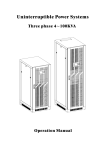
The TEF 4500 Commander Utility remote control system is extremely versatile and is comprised of three
main components:
Panels
Output modules
Serial Gateway
The components are interconnected via a RS-485 network (herein after called network). Each node has a
unique address, and one relay output module controls the network traffic by allowing one and only one
device to ‘talk’ at any given time. This network controller is selected with settings on the module.
The TEF 4500 Commander Utility system starts with a minimum of one panel and one relay output
module, up to a maximum of 7 panels and 21 relay output modules.
Each operator panel consists of a minimum of 24 buttons, up to a maximum of 64 buttons. The buttons
are stacked in columns of 8 buttons, and a maximum of 8 rows. The panels are backlit for easy reading of
text and graphics, in daylight as well as at night. The required number of relay output modules may be
connected, plus a 24VDC power supply, thus providing a compact and flexible control system.
One unique feature of the Commander Utility is the ability to divide the network into several domains,
which act as individual networks. There must be a minimum of one domain in the network, and a
maximum of 7.
Panels that are connected to the same network may have different sizes and different legends on the
buttons. Thereby they will seamlessly act as different domains on the network along with the output
modules they control. Another unique feature of the Commander Utility system allows identical panels to
be connected to the network so that these may work in full parallel. The system allows from 2 and up to all
7 panels to be identical on a single network, where a single action on one panel is replicated on all other
panels, including turning the system on or off.
Another feature is slave output modules. Slave mode can be used when two modules should react to the
same button presses on a panel.
The Serial Gateway introduces a serial interface towards the Commander Utility network, and allows twoway communication between the Commander Utility network and a VDR/SCADA system.
No customer-specific software or configuration is required, no matter the size of a system.
Application areas:
The Commander Utility system is designed specifically for marine use and has a contemporary design
with backlit front panels. The design is useful for a wide range of applications:
Deck light control panel
Floodlights
Helideck lighting
Heating systems
Pump control panel
Status panel for doors
Copyright © 2013 TRANBERG AS. All rights reserved. Page 6 of 34
General control panel
Features at a glance:
Relay modules with 24 relays @ 500mA (only to be used as pilot relays)
I/O modules with 24 inputs, 24 relay outputs @ 500mA (only to be used as pilot relays), and 3
alarm inputs.
Backlit operator panels with dimming feature
Optional Gateway that enables two-way communication (VDR/SCADA)
Common alarm input
External alarm reset
Audible and flashing LED alarm
NAUT-OSV compliant with dedicated alarm relay and bridge alarm reset relay
Up to 7 panels may be connected to a single network
The unique ‘Twin panels’ function allows 2 or more panels to work in precise parallel, allowing the
users to operate any of these panels to control the respective outputs.
The 'Slave mode’ function allows two output modules to react to the same button actions.
Section 2.02
System Overview
c o mma n d e r
s e r ie s
s e r ie s
c o mma n d e r
s e r ie s
4500801 Relay Output Module
24 x 1NO Outputs
Nominal current: 500mA 250VAC. Max. fuse 2A
c o mma n d e r
s e r ie s
Made in Norway
++ - 24VDC
Power
Rx Tx
Address
Fault
MODE DOMAIN
Rx Tx
Status
-Con3
24VDC
Power
4500801 Relay Output Module
24 x 1NO Outputs
Nominal current: 500mA 250VAC. Max. fuse 2A
c o mma n d e r
Made in Norway
++ - -
Address
Fault
Status
MODE DOMAIN
Rx Tx
Address
24VDC
Power
-Con3
Made in Norway
++ - -
MODE DOMAIN
-Con3
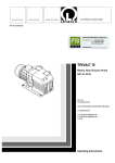
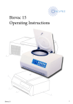
A generic diagram of a system setup is found below:
Fault
Status
c o mma n d e r
s e r ie s
4500801 Relay Output Module
24 x 1NO Outputs
Nominal current: 500mA 250VAC. Max. fuse 2A
c o mma n d e r
s e r ie s
Copyright © 2013 TRANBERG AS. All rights reserved. Page 7 of 34
c o mma n d e r
s e r ie s
Section 2.03
Network and domains
A network may consist of 1 to 7 domains. Below are examples describing different configurations.
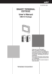
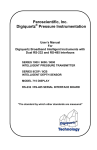
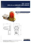
Application example 1: Single panel and relay output module
Panel settings:
ADR = 1
DOMAIN = 1
c o mma n d e r
Relay output module 1 settings:
Relay Module
Rx Tx
LSB
Fault
Status
c o mma n d e r
Made in Norway
Address
Power
A B Sh. Sh. A B Sh. Sh.
Comm. Port RS-485
MSB
24VDC
-Con4
-Con3
Part No.: 4900930
++ - -
s e r ie s
s e r ie s
DOMAIN = 1
MODE = 1
Max. 5A / 250V
Comments:
Relay output module 1 (with settings DOMAIN = 1 and MODE = 1), acts as the network controller.
The alarm input and alarm reset input is active on this module.
Relay 8 is automatically defined to activate as long as the systems is turned on.
Relay 16 is automatically defined to activate as long as an alarm is present.
Relay 24 will activate for a period of 1 second after a potential alarm has been acknowledged.
Copyright © 2013 TRANBERG AS. All rights reserved. Page 8 of 34
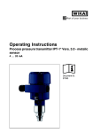
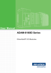
Application example 2: Twin panels and a common relay output module
Panel 1 settings:
Panel 2 settings:
ADR = 1
DOMAIN = 1
ADR = 2
DOMAIN = 1
c o mma n d e r
Rx Tx
LSB
Fault
Status
c o mma n d e r
s e r ie s
Made in Norway
Address
Power
A B Sh. Sh. A B Sh. Sh.
Comm. Port RS-485
MSB
-Con4
-Con3
24VDC
c o mma n d e r
Relay output module 1 settings:
Relay Module
Part No.: 4900930
++ - -
s e r ie s
s e r ie s
DOMAIN = 1
MODE = 1
Max. 5A / 250V
Comments:
Relay output module 1 (with settings DOMAIN = 1 and MODE = 1), acts as the network controller.
The alarm input and alarm reset input is active on this module.
Relay 8 is automatically defined to activate as long as the system is turned on.
Relay 16 is automatically defined to activate as long as an alarm is present.
Relay 24 will activate for a period of 1 second after a potential alarm has been acknowledged.
Both panels work in parallel together with the relay output module. Thus, both will reflect the
current state of the outputs, and both panels operate identically. This unique feature is called Twin
Panels. More on this in the Panels chapter.
Copyright © 2013 TRANBERG AS. All rights reserved. Page 9 of 34
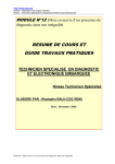
Application example 3: Two individual panels and two relay output modules
Panel 1 settings:
Panel 2 settings:
ADR = 1
DOMAIN = 1
ADR = 2
DOMAIN = 2
c o mma n d e r
s e r ie s
c o mma n d e r
Relay Module
c o mma n d e r
s e r ie s
Max. 5A / 250V
Power
Rx Tx
Fault
Status
c o mma n d e r
Made in Norway
LSB
A B Sh. Sh. A B Sh. Sh.
Comm. Port RS-485
Address
24VDC
-Con4
-Con3
LSB
Fault
Status
++ - -
MSB
Rx Tx
Relay Module
Part No.: 4900930
Made in Norway
Address
Power
A B Sh. Sh. A B Sh. Sh.
Comm. Port RS-485
MSB
24VDC
-Con4
-Con3
Part No.: 4900930
++ - -
s e r ie s
s e r ie s
Max. 5A / 250V
Relay output module 1 settings:
Relay output module 2 settings:
DOMAIN = 1
MODE = 1
DOMAIN = 2
MODE = 1
Comments:
Relay output module 1 (with settings DOMAIN = 1 and MODE = 1), acts as the network controller.
Both relay output modules communicates with their respective panels/domains.
The alarm input and alarm reset input is active on each module, and corresponds to each panel.
Relay 8 is automatically defined to activate as long as the corresponding domain is turned on.
Relay 16 is automatically defined to activate as long as an alarm is present in the corresponding
domain.
Relay 24 will activate for a period of 1 second after a potential alarm has been acknowledged for
the corresponding domain.
The two domains will appear independent of each other.
Copyright © 2013 TRANBERG AS. All rights reserved. Page 10 of 34
Application example 4: Two panels and three relay output modules
Panel 1 settings:
Panel 2 settings:
ADR = 1
DOMAIN = 1
ADR = 2
DOMAIN = 2
s e r ie s
c o mma n d e r
Rx Tx
c o mma n d e r
Max. 5A / 250V
24VDC
Power
A B Sh. Sh. A B Sh. Sh.
Comm. Port RS-485
Rx Tx
Fault
Status
s e r ie s
c o mma n d e r
Max. 5A / 250V
Made in Norway
LSB
++ - -
-Con4
LSB
Fault
Status
s e r ie s
Relay Module
Part No.: 4900930
Made in Norway
Address
Power
A B Sh. Sh. A B Sh. Sh.
Comm. Port RS-485
Address
24VDC
-Con4
-Con3
LSB
Fault
Status
c o mma n d e r
++ - -
MSB
Rx Tx
Relay Module
Part No.: 4900930
Made in Norway
Address
Power
A B Sh. Sh. A B Sh. Sh.
Comm. Port RS-485
MSB
-Con4
-Con3
24VDC
-Con3
Relay Module
Part No.: 4900930
++ - -
s e r ie s
MSB
c o mma n d e r
s e r ie s
Max. 5A / 250V
Relay output module 1 settings:
Relay output module 2 settings:
Relay output module 3 settings:
DOMAIN = 1
MODE = 1
DOMAIN = 2
MODE = 1
DOMAIN = 2
MODE = 2
Comments:
Relay output module 1 (with settings DOMAIN = 1 and MODE = 1), acts as the network controller.
Relay module 1 communicates with panel 1, while the other two relay output modules
communicate with panel 2. Hence, there are two domains in operation in this configuration.
The alarm input and alarm reset input is active on relay output module 1 and 2.
Relay 8 is automatically defined to activate as long as the corresponding domains are turned on.
Relay 16 is automatically defined to activate as long as an alarm is present in the corresponding
domain.
Relay 24 will activate for a period of 1 second after a potential alarm has been acknowledged for
the corresponding domains.
The two domains will appear independent of each other.
Copyright © 2013 TRANBERG AS. All rights reserved. Page 11 of 34
Chapter III.
Section 3.01
Panels
Overview
The panels come in five different lengths, depending on the number of buttons, but they all share the
same height.
Buttons are placed in a grid with 8 positions vertically and from 3 to 8 horizontally. All buttons are present
in a panel, regardless of being used or not. Please observe that each button will be functional in any case.
The button tops are injection molded in black color. In recesses on top of the buttons, Lexan films in
various colors and with or without openings for LEDs are inserted.
Text and graphics are laser engraved, enabling us to provide the users with clear and precise information,
readable in daylight as well as in the dark.
The construction consists of a machined, black aluminum frame with a recessed button surface made of
Lexan. The Lexan film is painted and laser engraved on the reverse side. This ensures a very durable
front.
Engraving may be done upon order or later in a project. A Lexan foil may be shipped to the customer at
any time and inserted in the panel without any disassembly.
Panel
TEF4901000
TEF4902000
TEF4903000
TEF4904000
TEF4905000
Buttons
3 x 8 = 24
5 x 8 = 40
6 x 8 = 48
7 x 8 = 56
8 x 8 = 64
Section 3.02
Available Buttons
21
37
45
53
61
Available Full-Size Buttons
21
29
37
45
53
Buttons and LEDs
Each button on a panel is given a unique definition, such as C3R4. C3 means Column 3, and R4 means
Row 4. Obviously, the first button then becomes C1R1, and the last available button will be C7R8.
The TEF 4500 Commander Utility is by design pre-arranged when it comes to buttons and relay actions.
The first three columns of buttons in a panel consist of 24 buttons (8 times 3). The lowest buttons in these
three columns are by default the following:
Power on/off (C1R8)
Backlight dimming (C2R8)
Alarm acknowledge (C3R8)
These buttons cannot have any other functions.
The three columns with buttons are reflected in a single relay output module, which have 24 relays. Relay
number 1 reflects the status of button number 1 (C1R1), relay number 2 is reflected in the button below
this (C1R2), and so forth.
Power button
Power on/off. A short press will turn the system on, while a longer press (approx. 1 second) is needed to
turn the system off. When off, all output modules will turn off all relays. When turned on again, all those
outputs that were turned on previously, will be turned on again. Relay number 8 in the bus master will be
Copyright © 2013 TRANBERG AS. All rights reserved. Page 12 of 34
activated as long as the system/domain is turned on. The definition of the bus master is explained in the
Output modules chapter.
The LED in the Power button will flash slowly when the panel is off, and will turn off when the panel is on.
Note that a yellow, fast flashing Power button LED and an activated buzzer in the panel indicates a
communications error between the panel and the rest of the network.
Backlight level button
The panel background is illuminated by means of side-emitting LEDs inside the panel. These illuminate
text and graphics. Press and hold the Backlight level button to regulate the light intensity upwards or
downwards.
Alarm acknowledge button
Once an alarm is given, relay number 16 in the primary relay output module will activate, and will stay
activated as long as the alarm is present. A single press on the Alarm Acknowledge button, or an external
signal to the Alarm Silence Input on the associated primary output module, will turn off the buzzer in the
panel and acknowledge the alarm given. As an alarm is acknowledged, relay number 24 will activate for a
period of 1 second, and the contacts on this relay may be used as an interface with the Bridge Alarm
System. No relays will be activated if it is a network error alarm.
Button LEDs
Each button has one green LED in the upper left corner. This normally indicates whether the
corresponding relay output is on or off. There is also a red LED in the upper right corner of each button.
The LEDs may have different meanings depending on the settings on the output module.
Alarm LEDs
Depending on what type of output module a panel controls, it comes with two or four alarm LEDs.
The Network error LED will flash upon a network error.
The Alarm 1 LED will flash when a signal is provided onto the Alarm 1 Input on the relay output
module.
Only on panels with four alarm LEDs:
The Wakeup LED will flash when a signal is provided onto the Wakeup Input on the relay output
module.
The Alarm 2 LED will flash when a signal is provided onto the Alarm 2 Input on the relay output
module.
The audible alarm will sound on all alarms. The alarm is silenced by pressing the Alarm Acknowledge
button (or via an external signal to the Alarm Silence input on the relay output module), at which time the
LED will light continuously until the error has disappeared.
The alarm LEDs will light up in different patterns, depending on the state of the alarm:
Pattern
Fast flash
Steady on
Two fast flashes, then 1 sec. pause
Off
State
Unacknowledged alarm
Acknowledged alarm present
Unacknowledged alarm, not present anymore
No alarm
Copyright © 2013 TRANBERG AS. All rights reserved. Page 13 of 34
If the panel is turned off and on again while there are alarms present, the audible alarm will sound and the
corresponding alarm LED will flash yet again.
LED testing
By pressing the Acknowledge button for more than 5 seconds, a LED test procedure is invoked: All green
LEDs will flash on for almost one second, and then the red LEDs will flash similarly. This procedure will
repeat until the button is pressed a second time, and has no effect on the original LED status.
Section 3.03
Settings
Address
The address of the panel is set on the rear at the dial labeled ADR. This is preset by the factory, typically
at address 1. See table below.
Panel numbers
1
2
3
4
5
6
7
ADR switch setting
0
1
2
3
4
5
6
7
Comments / labelling
DO NOT USE
P1
P2
P3
P4
P5
P6
P7
The ADR setting should always be a unique number. There must not be two panels on the same network
with the same number, as that will lead to data packet collisions on the network.
Domain
Select the DOMAIN setting as required. Up to 7 DOMAINS may be defined, which in practice acts as
independent ‘systems’ on the single network.
DOMAIN for a panel
1
2
3
4
5
6
7
DOMAIN switch setting
0
1
2
3
4
5
6
7
Comments / labelling
DO NOT USE
D1
D2
D3
D4
D5
D6
D7
Normally the DOMAIN setting is identical to the ADDRESS setting on the same panel (same number).
Twin panel
However, when using two or more panels, setting the DOMAIN number equal to another panel’s DOMAIN
setting, provides you with the possibility of having twin panels (two or more panels working identically and
in parallel). Examples are given in the table below:
Copyright © 2013 TRANBERG AS. All rights reserved. Page 14 of 34
ADR switch setting
0
1
2
3
4
5
DOMAIN switch setting
0
1
1
1
4
4
Comments
DO NOT USE
Panel 1 is normally set
Panel 2 is twin to panel 1
Panel 3 is also twin to panel 1
Panel 4 is normally set
Panel 5 is twin to panel 4
Status LEDs
These LEDs are located on the back of the panel.
LED
Pwr
Rx
Tx
Color
Green
Yellow
Yellow
Fault
Red
Status
Steady on
Flicker
Flicker
Steady on
Fast blink
Slow blink
Off
Description
24VDC is present.
The module receives messages from the bus
The module sends messages on the bus
Functional error
Network error: No messages received
Network error: The module receives messages on the bus, but none
to its own address
Module and outputs OK
Slow blink: 1 sec. on, 1 sec. off.
Fast blink: 2 blinks per second.
Section 3.04
Connection diagram
Copyright © 2013 TRANBERG AS. All rights reserved. Page 15 of 34
Chapter IV.
Section 4.01
Output modules
Overview
The different output modules available are:
4500801
Relay output module with 24 relays
4500802
Relay input/output module with 24 optically isolated inputs and 24 relay outputs
Section 4.02
Bus master
The network needs a network controller. Depending on the settings on an output module, it can be set as
a bus master. The bus master acts as a network controller, and coordinates the bus activity. There must
be one, and only one, bus master on the network. For selecting the bus master, see the settings tables for
each module.
Section 4.03
4500801
Made in Norway
++ - -
MODE DOMAIN
24VDC
Power
Rx Tx
Address
-Con3
Relay output module with 24 relays. The relays are only to be used as pilot relays for larger
relays/contactors that should do the actual circuit breaking. All relays are single pole, potential free,
‘Normally Open’ (NO) and rated at 500mA / 250VAC continuous.
Fault
Status
c o mma n d e r
s e r ie s
4500801 Relay Output Module
24 x 1NO Outputs
Nominal current: 500mA 250VAC. Max. fuse 2A
Special Inputs / Outputs
Copyright © 2013 TRANBERG AS. All rights reserved. Page 16 of 34
Input
Ext. Alarm
Input
Function
Alarm 1
Alarm
Silence
Alarm silence
Output
no.
8
16
24
Terminals
no.
15 – 16
31 – 32
47 – 48
Comment
Activates alarm relay and indicator 'Alarm 1' on panel. Available as both
a 24VDC optically isolated input, or as a set of open contacts that upon
closing will activate the alarm input.
Silences the alarm. Available as both a 24VDC optically isolated input, or
as a set of open contacts that upon closing will deactivate the alarm
state.
Function
Comment
Power on
Alarm
Alarm ack.
Active when system power is on.
Active when the alarm input is activated.
Pulsed for 1 sec. after alarm silence input or silence button on
panel has been activated.
Settings
The addresses of the modules are required to ensure proper operation. There are two dials labeled
DOMAIN and MODE that set the address on each module. DOMAIN should be set to match that of the
DOMAIN setting on the corresponding panel, while MODE should be set according to the table below.
Note that each module must have its own unique address on the network!
Do not change the addresses. If replacing a module, please ensure that the address of the new module is
identical to the address of the old module.
Address settings:
Address
1
DOMAIN
0
1
MODE
0
1
2
3
4
5
6
7
8
9
10
11
12
13
14
15
16
17
18
19
20
21
1
1
2
2
2
3
3
3
4
4
4
5
5
5
6
6
6
7
7
7
2
3
1
2
3
1
2
3
1
2
3
1
2
3
1
2
3
1
2
3
Comments / labeling
Do not use
Domain 1, columns 1, 2, and 3 in panel.
Acts as a network controller / bus master
Domain 1, columns 4, 5, and 6 in panel.
Domain 1, column 7 in panel.
Domain 2, columns 1, 2, and 3 in panel.
Domain 2, columns 4, 5, and 6 in panel.
Domain 2, column 7 in panel.
Domain 3, columns 1, 2, and 3 in panel.
Domain 3, columns 4, 5, and 6 in panel.
Domain 3, column 7 in panel.
Domain 4, columns 1, 2, and 3 in panel.
Domain 4, columns 4, 5, and 6 in panel.
Domain 4, column 7 in panel.
Domain 5, columns 1, 2, and 3 in panel.
Domain 5, columns 4, 5, and 6 in panel.
Domain 5, column 7 in panel.
Domain 6, columns 1, 2, and 3 in panel.
Domain 6, columns 4, 5, and 6 in panel.
Domain 6, column 7 in panel.
Domain 7, columns 1, 2, and 3 in panel.
Domain 7, columns 4, 5, and 6 in panel.
Domain 7, column 7 in panel.
Copyright © 2013 TRANBERG AS. All rights reserved. Page 17 of 34
Slave mode
Slave mode can be used when two modules should react to the same button presses on a panel. Both
modules’ outputs will be equal, but the slave does not react to alarm input or alarm silence signals. The
slave module does not send any feedback to the panel, and the status LEDs in the panel will therefore
only reflect the Main Module’s status.
To put a module in slave mode, follow these settings:
Mode (Main Module)
1
2
3
Mode (Slave Module)
4
5
6
Note: DOMAIN setting must be equal on both modules!
Status LEDs
These LEDs are located on the top of the module.
LED
Pwr
Rx
Tx
Color
Green
Yellow
Yellow
Fault
Red
Status
Steady on
Flicker
Flicker
Steady on
Fast blink
Slow blink
Off
Description
24VDC is present.
The module receives messages from the bus
The module sends messages on the bus
Functional error
Network error: No messages received
Network error: The module receives messages on the bus, but none
to its own address
Module and outputs OK
Slow blink: 1 sec. on, 1 sec. off.
Fast blink: 2 blinks per second.
Copyright © 2013 TRANBERG AS. All rights reserved. Page 18 of 34
Connection diagram
Copyright © 2013 TRANBERG AS. All rights reserved. Page 19 of 34
Section 4.04
4500802
Made in Norway
++ - -
MODE DOMAIN
24VDC
Power
Rx Tx
Address
-Con3
Relay input/output module with 24 optically isolated inputs, 24 relay outputs and 3 optically isolated alarm
inputs. The relays are only to be used as pilot relays for larger relays/contactors that should do the actual
circuit breaking. All relays are single pole, potential free, ‘Normally Open’ (NO) and rated at 500mA /
250VAC continuous.
Fault
Status
4500802 Relay Output / Digital Input Module
24 x 1NO Outputs. Nominal current: 500mA 250VAC. Max. fuse 2A
24 + 3 Digital Inputs. 24VDC 10mA
c o mma n d e r
s e r ie s
Special Inputs / Outputs
Input no.
25 / AL1
26 / AL2
27 / AL3
Terminals
no. X3:
1–2
3–4
5–6
Input
no.
8
16
Terminals
no. X2:
15 – 16
31 – 32
24
47 – 48
Output
no.
8
16
24
Terminals
no. X1:
15 – 16
31 – 32
47 – 48
Function
Comment
Alarm 1
Alarm 2
Wakeup alarm
Activates alarm relay and indicator 'Alarm 1' on panel.
Activates alarm relay and indicator 'Alarm 2' on panel.
Activates alarm relay and indicator 'Wakeup' on panel. Turns
on power.
Function
Comment
Power on
Force power
on
Alarm silence
Falling edge toggles on or off.
System is always on as long as this input is high.
Function
Comment
Power on
Alarm
Alarm ack.
Active when system power is on.
Active when the alarm input is activated.
Pulsed for 1 sec. after alarm silence input or silence button on
panel has been activated.
Rising edge silences the alarm
Copyright © 2013 TRANBERG AS. All rights reserved. Page 20 of 34
Settings
The addresses of the modules are required to ensure proper operation. There are two dials labeled
DOMAIN and MODE that set the address on each module. DOMAIN should be set to match that of the
DOMAIN setting on the corresponding panel, while MODE should be set according to the tables below.
Note that each module must have its own unique address on the network!
Do not change the addresses. If replacing a module, please ensure that the address of the new module is
identical to the address of the old module.
Address settings:
Address
1
DOMAIN
0
1
MODE
0
1/7
2
3
4
5
6
7
8
9
10
11
12
13
14
15
16
17
18
19
20
21
1
1
2
2
2
3
3
3
4
4
4
5
5
5
6
6
6
7
7
7
2/8
3/9
1/7
2/8
3/9
1/7
2/8
3/9
1/7
2/8
3/9
1/7
2/8
3/9
1/7
2/8
3/9
1/7
2/8
3/9
Comments / labeling
Do not use
Domain 1, columns 1, 2, and 3 in panel.
Acts as a network controller / bus master
Domain 1, columns 4, 5, and 6 in panel.
Domain 1, column 7 in panel.
Domain 2, columns 1, 2, and 3 in panel.
Domain 2, columns 4, 5, and 6 in panel.
Domain 2, column 7 in panel.
Domain 3, columns 1, 2, and 3 in panel.
Domain 3, columns 4, 5, and 6 in panel.
Domain 3, column 7 in panel.
Domain 4, columns 1, 2, and 3 in panel.
Domain 4, columns 4, 5, and 6 in panel.
Domain 4, column 7 in panel.
Domain 5, columns 1, 2, and 3 in panel.
Domain 5, columns 4, 5, and 6 in panel.
Domain 5, column 7 in panel.
Domain 6, columns 1, 2, and 3 in panel.
Domain 6, columns 4, 5, and 6 in panel.
Domain 6, column 7 in panel.
Domain 7, columns 1, 2, and 3 in panel.
Domain 7, columns 4, 5, and 6 in panel.
Domain 7, column 7 in panel.
The different modes of operation:
Domain
0
Mode
0
sw4
x
sw3
x
sw2
x
Description
Self test
1-7
1-7
1-7
1-7
1-7
1-7
1-7
1-7
1-3
1
1-3
off
off
off
off
ON
ON
ON
ON
off
off
ON
ON
off
off
ON
ON
off
ON
off
ON
off
ON
off
ON
off
off
off
off
off
ON
Standard
Power supply monitor
Radio remote
Motor protection
1-7
1-7
7
Copyright © 2013 TRANBERG AS. All rights reserved. Page 21 of 34
1-7
1-7
1-7
1-7
1-7
1-7
7-9
7
off
off
ON
ON
ON
ON
ON
ON
off
off
ON
ON
off
ON
off
ON
off
ON
Monitor
Earth fault
-
This switch can be used to invert the inputs, i.e. a high input will be treated as a low input and vice versa.
sw1
Off
On
Input
NOT Inverted
Inverted
Modes of operation
Self test
This mode can be used to test each output relay. Each output is turned on in sequence, and then off
again, before it starts over again.
Standard
In this mode the outputs, in addition to be controlled by the panel, are controlled by the inputs. The
inputs control the outputs in a toggle fashion, i.e. one pulse on the input turns the corresponding
output on, while the next pulse turns it off. It is the negative going edge on the input that triggers the
change in output. In this way, a simple pushbutton can be connected to an input to control the output.
It also allows for the panel and inputs to function in parallel, i.e. a pulse on the input or a key press on
the panel will both change the output.
Power supply monitor
This mode monitors two inputs, 9 and 10. This can be used to control which power supply to be used
under certain conditions. The inputs monitor supply 1 and 2. If one of them drops out, a signal can be
given to switch supply.
Outputs 9 and 10 are mutually exclusive, 1 sec. switchover pause (break before make)
Input 9
High
Low
High
Low
Input
9
10
Input 10
High
High
Low
Low
Output
9
10
Output 9
On
Off
On
On
Output 10
Off
On
Off
Off
Description
Supply 1
Supply 2
If one of the inputs goes low, the Alarm acknowledge button will flash red, and the alarm buzzer will
sound. When the Alarm acknowledge button is pressed, the buzzer will stop and the red LED will turn
off.
Radio remote
The radio remote mode is to be used with a 10 buttons / relays radio remote control. It will control the
first 24 keys / outputs on a panel / module. The 10 relay outputs from the radio control are connected
to the corresponding 10 first inputs on the I/O module. Inputs 1 – 8 functions the same way as the 8
Copyright © 2013 TRANBERG AS. All rights reserved. Page 22 of 34
first keys on the panel (first column), and key 9 and 10 on the radio control functions as shift keys
selecting the next two key columns / outputs on the module, respectively.
Motor protection mode:
When a button is pressed, the corresponding output is turned on, and the button starts flashing its
green LED. After a delay of 3 seconds, the corresponding input is read. If the input is high, the button
LED turns steady green. To turn the output off, press the button once more.
If the input is low, the button LED starts flashing red, and the buzzer will sound. The
acknowledge/silence button needs to be pressed to silence the alarm, and all flashing LEDs will turn
on steady. The outputs are not affected by an alarm, and pressing a button with a red LED will turn
the output off (and silence the alarm).
A button with a steady green LED will start flashing red and the buzzer will sound if its input goes low.
Monitor
In this mode, each button controls the corresponding output in a toggle fashion. The button LED is
steady green when the corresponding input is low and steady red when the input is high.
Earth fault mode:
Buttons control outputs as usual, with green LED indicating output is on. A high input indicates an
error in that channel, and is indicated on the panel by the red LED. If the output is on when the error
occur, the output will be turned off, the red LED in the button will flash and the buzzer will sound. The
acknowledge/silence button needs to be pressed to silence the alarm. Then the red LED will turn on
steady. If the output is off, the red LED will go directly to the steady on state, and no buzzer will
sound. When the red LED is on or flashing, the output is not allowed to turn on. The red LED is
controlled only by the input, it is not possible to turn it off by the button.
Status LEDs
These LEDs are located on the top of the module.
LED
Pwr
Rx
Tx
Color
Green
Yellow
Yellow
Fault
Red
Status
Steady on
Flicker
Flicker
Steady on
Fast blink
Slow blink
Off
Description
24VDC is present.
The module receives messages from the bus
The module sends messages on the bus
Functional error
Network error: No messages received
Network error: The module receives messages on the bus, but none
to its own address
Module and outputs OK
Slow blink: 1 sec. on, 1 sec. off.
Fast blink: 2 blinks per second.
Copyright © 2013 TRANBERG AS. All rights reserved. Page 23 of 34
Connection diagram
Copyright © 2013 TRANBERG AS. All rights reserved. Page 24 of 34
Chapter V.
Section 5.01
Serial Gateway
Overview
The Commander Utility Gateway introduces a serial interface towards the Commander Utility network, and
may be used together with a VDR/SCADA system. The gateway consists of two unidirectional interfaces,
one in each direction. These communication channels operate independent of each other, and directly
towards the internal bus communication and bus master.
It uses the RS-422 standard at 38400 baud with 8 data bits, no parity and 1 stop bit (8N1).
-Con3
The Gateway has a predefined address on the bus, and therefore it doesn’t need any settings setup.
Y Z B A
Comm. Port RS-422
1
2
Comm. Port RS-485
PE PE Ref Ref
Made in Norway
Commander Utility Gateway - Part No. 4500800
c o mma n d e r
Pwr. N.C. N.C. N.C.
s e r ie s
N.C.
N.C.
N.C.
N.C.
Section 5.02
+ - + - + - + - + + - -
1 2 3 4 5 6 7 8 9 10 11 12
-Con2
-Con1
24VDC
+ -
1 2 3 4 5 6 7 8
RS-422 Serial Interface
The gateway communicates with external equipment through its RS-422 interface at 38400 baud with 8
data bits, no parity and 1 stop bit (8N1).
A: TXD+
B: TXDY: RXD+
Z: RXD-
Section 5.03
Node addressing
Maximum number of panels: 7
Maximum number of output modules: 21
Gateway node has a predefined address.
Copyright © 2013 TRANBERG AS. All rights reserved. Page 25 of 34
Each (main) panels address also gives the domain address for the panels and relay modules that are
logically connected. An unused address is used as a broadcast address that every node on the network
listens to.
Address
scada
ASCII
‘(‘
Dec
40
The scada node
broadcast
0
48
Broadcast domain
panel1
panel2
panel3
panel4
panel5
panel6
panel7
1
2
3
4
5
6
7
49
50
51
52
53
54
55
Domains
module01
module02
module03
module04
module05
module06
module07
module08
module09
module10
module11
module12
module13
module14
module15
module16
module17
module18
module19
module20
module21
A
B
C
D
E
F
G
H
I
J
K
L
M
N
O
P
Q
R
S
T
U
65
66
67
68
69
70
71
72
73
74
75
76
77
78
79
80
81
82
83
84
85
1+0
1+1
1+2
2+0
2+1
2+2
3+0
3+1
3+2
4+0
4+1
4+2
5+0
5+1
5+2
6+0
6+1
6+2
7+0
7+1
7+2
Section 5.04
Description
Messages from gateway / system (VDR)
Typical message (ASCII):
$PTRA,E,1,0,#,1,FFFFFF*CC<CR><LF>
Where CC is a 2 digit ASCII hex checksum, MSB first.
Message format (comma separated fields):
No
1
2
3
Field
Header
Message command
Domain no.
Bytes
1
1
1
Value
‘$PTRA‘
‘A’ to ‘H’
‘1’ – ‘7’
Comment
Always the same
Copyright © 2013 TRANBERG AS. All rights reserved. Page 26 of 34
4
5
6
7
Domain status/request
Channel no.
Channel state/data
Channels applicable
1
1
1
0, 2, 4, 6
ASCII hex
8
Checksum
2
ASCII hex
9
Footer
Sum bytes:
2
8, 10, 12, 14
<CR><LF>
Optional (1, 8, 16, 24 channels,
dependent on channel no.)
XOR of all characters between '$' and
'*', excluding '$', '*' and comma
delimiter ','.
2. Message commands:
Value
65
66
67
68
69
70
71
72
ASCII
A
B
C
D
E
F
G
H
Name
button
level input
current-sense
error-input
output-status
helideck
multistate
sync
Comment
From panel
Not used
Not used
Not used
From relay module 4500801, state of relay outputs
Only used in 24 I/O module 4500802
Only used in 24 I/O module 4500802
Only used in 24 I/O module 4500802
3. Domain number:
Possible domains are ‘1’ to ‘7’, '1' is normally used. Use '2' and more when connecting several systems
on the same bus.
4. Domain status/request:
Status is sent out from relay-module no. 0 (for buttons 1 – 21) in each domain. Status req. (request) is
sent out from the other modules in the system (for each domain). The relay module 0 determines the
status after receiving the status request from the other modules in the domain. This is to avoid any
ambiguities about the status.
No.
Status
0
1
2
3
4
5
6
7
8
9
10
11
12
13
14
15
16
‘/’
‘0’
‘1’
‘2’
‘3’
‘4’
‘5’
‘6’
‘7’
‘8’
‘9’
‘:’
‘;’
‘<’
‘=’
‘>’
‘?’
Status
req.
‘O’
‘P’
‘Q’
‘R’
‘S’
‘T’
‘U’
‘V’
‘W’
‘X’
‘Y’
‘Z’
‘[’
‘\’
‘]’
‘^’
‘_’
Power
0
1
1
1
1
1
1
1
1
1
1
1
1
1
1
1
1
Sound
x
0
0
0
0
0
0
0
0
1
1
1
1
1
1
1
1
Wake
up
x
0
0
0
0
1
1
1
1
0
0
0
0
1
1
1
1
Alarm2
x
0
0
1
1
0
0
1
1
0
0
1
1
0
0
1
1
Alarm1
x
0
1
0
1
0
1
0
1
0
1
0
1
0
1
0
1
Copyright © 2013 TRANBERG AS. All rights reserved. Page 27 of 34
Comment
5. Channel numbering:
The system can use up to 64 channels (input, output etc.) in one domain. These channels can be
addressed in 4 different ways/group sizes: 24, 16, 8 and 1, depending on the value of the numbering
byte:
Value
33
34
35
36
37
38
39
40
41
42
43
44
45
46
47
49 - 112
ASCII
‘!’
‘"’
‘#’
‘$’
‘ % ‘’
‘&’
‘'’
‘(’
‘)’
‘*’
‘+’
‘,’
‘-’
‘.’
‘/’
‘1’ – ‘p’
Size
24
24
24
16
16
16
16
8
8
8
8
8
8
8
8
1
Bytes
6
6
6
4
4
4
4
2
2
2
2
2
2
2
2
0
Channels
0 – 23
24 – 47
48 – 71
0 – 15
16 – 31
32 – 47
48 – 63
0–7
8 – 15
16 – 23
24 – 31
32 – 39
40 – 47
48 – 55
56 – 63
0, 1, 2, ..., 61, 62, 63
Comment
64 – 71 is not used
Consecutive values
The size used depends on the type of message and module. A button message from a panel uses size
1 identifying the channel relating to only that particular button, while a relay module with 24 output
relays, uses a message with the status of all 24 outputs in one message.
6. Channel data:
The channel data shows the data (level or state) of the channel(s) indicated by the channel numbering
byte.
7. Channel applicable:
This can be regarded as a bit mask showing the channels in the group for which the data is valid (high),
and for which the data is not valid (low). The mask is represented as an ASCII hexadecimal value, MSB
to the left. It can also be a data value, depending on the command.
Ex.: $PTRA,E,1,0,!,1,0000A0*32 :
0000A0 (hex) = 0000 0000 0000 0000 1010 0000 (binary). The channel data ('1') in this message is
valid only for channel 5 and 7 (channel 0 = least significant bit, to the right). ' ! ' indicates channel
numbers are 0 – 23.
(Note that outputs 7, 15 and 23 have special functions on relay module 4500801: 7 = power on/off, 15 =
alarm on/off, 23 = alarm reset. See also the Commander utility user manual)
Section 5.05
Messages to system (SCADA)
The input port to the gateway must be recognized by the bus master (relay module with address set to
1) at power up. Therefore it is important that the gateway is power up before or at least at the same time
as the bus master.
The 'ACTIVE' LED on the gateway will light up when the output port is online and ready to receive
external commands. After receiving a command, it will switch off to indicate that the command is now
processed. No further commands can be received in this period.
Copyright © 2013 TRANBERG AS. All rights reserved. Page 28 of 34
The typical use of the input port is to imitate a panel, sending buttons commands into the system.
Typical message (ASCII):
$PTRA,A1053*CC
- button command (A)
- domain 1
- no change in status (0)
- button no. 5 has recently been released (3).
Message format:
No
1
2
3
4
5
Field
Header
NMEA comma
Command message
NMEA separator
Checksum
Bytes
1
1
5 or more
1
2
Value
‘$PTRA‘
‘,’
See below
'*'
ASCII hex
Comment
Always the same
Sent out on the internal bus
XOR of all characters between '$' and
'*', excluding '$', '*' and comma
delimiter ','.
Command message format:
No
Field
Bytes
Value
Comment
1
Message command
1
‘A’ to ‘H’
2
Domain
1
‘1’ – ‘7’
3
Status / status request
1
'0' when no change
4
Channel no.
1
Button no.
5
Channel state
1
Depressed or released
6
Channels data
0, 2, 4, 6
ASCII hex
optional (1, 8, 16, 24 channels)
For commands and formatting, see previous chapter on output port (VDR).
The panel sends out the different states of the buttons. The relay module responds to a button release,
a falling edge on the button. This will toggle the corresponding output relay.
ASCII
Level
Comment
'0'
low level
'1'
high level
'2'
rising edge
'3'
falling edge
Button released
(When no buttons are operated, the panel sends a dummy message with '0' in channel and in state.)
Copyright © 2013 TRANBERG AS. All rights reserved. Page 29 of 34
Section 5.06
Connection diagram
Copyright © 2013 TRANBERG AS. All rights reserved. Page 30 of 34
Chapter VI.
Section 6.01
Installation
Physical Placement
The panels and the other components may be physically installed with a distance of theoretically up to
hundreds of meters. However, we recommend that all output modules and the master controller are
physically located near each other.
Panels should be fixed to the bridge or similar place by means of four screws.
Modules should be mounted on a 35mm DIN-rail by using the spring-loaded clamp on the rear side of the
module.
Section 6.02
Power cables
All modules should be powered from the same 24VDC supply. All modules have dual terminals, so they
may be terminated in a daisy chain from module to module.
Use 0.5 – 1.0 mm² wires.
Section 6.03
Communication cables
All modules should be connected to the same physical network. All modules have dual RJ-45 terminals,
and must be connected in a daisy chain from module to module. The communication cable must not be
connected in a loop; it should always be end to end.
The communication cables should be shielded and have a minimum of 2 twisted pairs. Characteristic
impedance: 100-250 ohm. Suitable cable types can be cables made for Profibus, Interbus, Ethernet, Cat5,
Cat6, or similar.
Never use an end-of-line resistor in the network. The communication circuitry has built-in serial resistors in
the A and B lines to avoid damage occurring from a short or similar.
Note: Keep communication cables away from power lines.
Copyright © 2013 TRANBERG AS. All rights reserved. Page 31 of 34
Section 6.04
Applying power for the first time
Before applying power for the first time, do the following:
Ensure all termination is correct and properly done.
Ensure that all panels and output modules have the correct settings.
Apply power to the power sources that feed the network. If supplied by different power supplies –
power up the bus master last!
All connected modules as well as the panels should now be powered:
All connected modules should light up a green LED (Power) indicating power is present.
Each connected module is queried by the network controller, and as each module replies, a
yellow LED (Tx) is lit up for a fraction of a second.
Section 6.05
Testing the system
Start the system testing:
Turn the panel off by pressing the power button in the lower left corner for a couple of seconds.
The backlit display will turn off and the yellow LED inside the power button will flash. When a
panel is turned off, all corresponding outputs will be turned off on that DOMAIN. Even though the
panel is turned off, all communication in the system continues. If there are more than one
DOMAIN active on the network, turn off the other panels as well.
Turn the panel(s) back on. The yellow LED in the power button will turn off, and the panel
backlight will turn on again.
Test the various functions by pressing each button and verify that its intended operation is carried
out according to the settings on the output module. If there is any unexpected behavior, check the
wiring or configuration settings.
Always refer to the system configuration and/or termination drawings when testing a system.
Section 6.06
Troubleshooting
If a failure is detected:
Ensure that the settings on all panels and output modules are correct.
Ensure that the output is terminated correctly.
Check whether the corresponding output module responds to the action. It does so by flashing the
Rx LED (yellow) rapidly, but it should also flash the Tx LED (yellow) about once per second or
more often. Missing the Tx signal may indicate bad communications termination, mix-up of the A
and B-lines or similar.
Turn all power off and reapply power. If supplied by different power supplies – power up the bus
master last! Then start testing over again.
Network failures:
If the yellow LED in the Power button in the panel is flashing fast, it may indicate a faulty
connection towards the panel. If the other modules in the system work properly (flashing RX and
TX) LEDs, the fault is somewhere between the panel and the rest of the system. Check the
communications cable and connections. Possible reasons may be that the A and B lines are
switched, if so, reconnect and try again.
If the red LED in an output module lights up, it is an indication that this particular module have no
connection to the network. Possible reasons may be that the A and B lines are not connected or
switched. If so, reconnect and try again.
Copyright © 2013 TRANBERG AS. All rights reserved. Page 32 of 34
LEDs in the panel turn on and off randomly:
Ensure that there is only one master on the bus.
If two or more masters are found, change settings and restart the system.
One or more columns on a panel are not functional:
Remove power from the panel
Write down the positions of both ‘ADR’ and ‘DOMAIN’ on the back of the panel before setting both
of them to ‘0’.
Reapply power
Press a button in the rightmost column
Remove power and set ‘ADR’ and ‘DOMAIN’ to the previous settings before reapplying power.
If a module needs to be replaced, ensure the following:
Disconnect main power.
Disconnect the terminal plugs to the module
Disconnect the wires from the output module to the external power relays.
Remove the module by tilting it towards its rear side (opposite/reverse of text on module top).
Check the address setting on the faulty module, and set the exact same address on the new
module.
Insert a new module, and then connect the various plugs.
Reapply power and test according to chapters Applying power for the first time and Testing the
system.
If the failure has been corrected, label the new module in the same way as the faulty module, e.g.
M3, and set a sticker on top of the address dial switch to avoid anyone altering this.
Copyright © 2013 TRANBERG AS. All rights reserved. Page 33 of 34
Chapter VII.
Section 7.01
Additional Information
Technical Clarifications
Please contact TRANBERG AS regarding clarifications:
Visiting address
Postal address
Strandsvingen 6
PO Box 8033
N-4032 Stavanger
N-4068 Stavanger
NORWAY
NORWAY
Tel: +47 51 57 89 00
Fax: +47 51 57 89 50
Copyright © 2013 TRANBERG AS. All rights reserved. Page 34 of 34