1
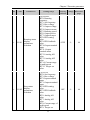
Chapter 5 Function parameter
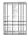
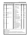
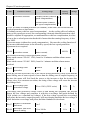
Code
Parameter name
Setting range
Factory
default
Change
Output
voltage
Vb
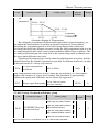
Vboost
Output
frequency
fb
f(cut-off)
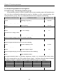
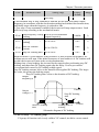
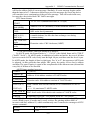
Schematic diagram of manual torque boost voltage
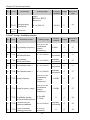
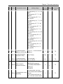
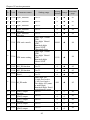
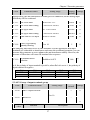
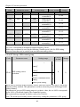
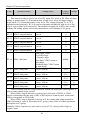
F4.03 V/F frequency point 1
0.00Hz to F4.05
0.00Hz
★
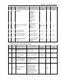
F4.04 V/F voltage point 1
0.0% to 100.0%
0.0%
★
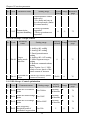
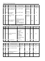
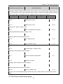
F4.05 V/F frequency point 2
F4.03 to F4.07
0.00Hz
★
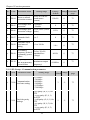
F4.06 V/F voltage point 2
0.0% to 100.0%
0.0%
★
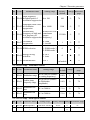
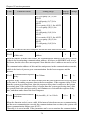
F4.05 to b0.04 (rated motor
0.00Hz
frequency)
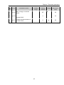
F4.07 V/F frequency point 3
F4.08 V/F voltage point 3
0.0% to 100.0%
0.0%
★
★
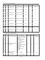
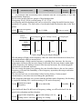
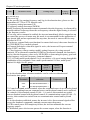
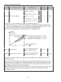
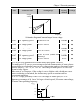
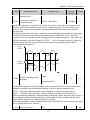
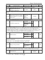
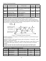
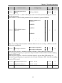
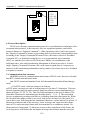
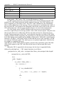
F4.03 to F4.08 six parameters are used to define multi-point V/F curve.
The multi-point V/F curve is set according to the load characteristics of motor, please
be noted that the relationship between three voltage points and three frequency points
must be meet: V1 <V2 <V3, F1 <F2 <F3. The setting of multi-point V/F curve is as
shown in below figure.
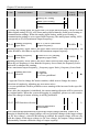
In the sate of low frequency, if the voltage is set to a higher value, which may cause
motor overheating even burned, the inverter may appear overcurrent stall or
overcurrent protection.
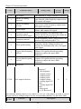
V1 to V3: voltage percentage of the 1st to 3rd stages of multi-speed; F1 to F3:
frequency percentage of the 1st to 3rd stages of multi-speed; Vb: motor rated voltage;
Fb motor rated operating frequency.
电压%
Voltage%
VbVb
V3
V2
V1
F1
F2
63
F3 Fb
Frequency
频率%