1
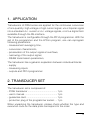
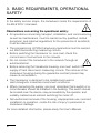
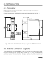
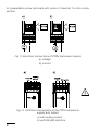
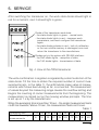
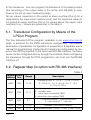
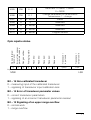
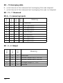
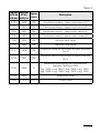
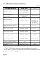
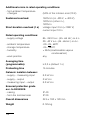
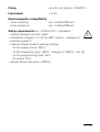
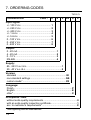
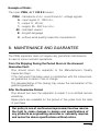
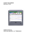
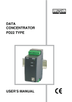
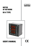
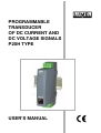
PROGRAMMABLE TRANSDUCER OF DC CURRENT AND DC VOLTAGE SIGNALS P20H TYPE USER’S MANUAL Contents: 1. APPLICATION . ............................................................................5 2. TRANSDUCER SET .....................................................................5 3. OPERATIONAL SAFETY . ...........................................................6 4. INSTALLATION . ..........................................................................7 4.1.Fixing Way .............................................................................7 4.2.External Connection Diagrams ..............................................7 5. SERVICE ......................................................................................9 5.1. Transducer Configuration by Means of the LPCon Program.....10 5.2.Register Map (in option with RS-485 Interface) . .................10 5.3.Manufacturer’s Parameters . ................................................14 6. TECHNICAL DATA ....................................................................15 7. ORDERING CODES ...................................................................18 8. MAINTENANCE AND GUARANTEE . .......................................19 1. APPLICATION Transducers of P20H series are applied for the continuous conversion of one quantity: high voltage or high current signal, uni or bipolar signal into a standard d.c. current or d.c. voltage signals, or into a digital form available through the RS-interface. The transducer is configurable through the PD14 programmer. With the aid of the programmer and the LPCon program, one can reprogram following parameters: - measurement averaging time, - conversion characteristic, - preservation of the output signal at overflows, - narrowing of the output signal, - RS485 transmission parameters, The transducer has a galvanic separation between individual blocks: - supply - measuring inputs - outputs and PD14 programmer 2. TRANSDUCER SET The transducer set is composed of: - P20H transducer............................................. 1 pc - user’s manual.................................................. 1 pc - guarantee card............................................... 1 pc - protection plug of the programmer socket..... 1 pc When unpacking the transducer, please check whether the type and execution code on the data plate correspond to the order. 3. BASIC REQUIREMENTS, OPERATIONAL SAFETY In the safety service scope, the transducer meets the requirements of the EN 61010-1 standard. Observations concerning the operational safety: · All operations concerning transport, installation, and commissioning as well as maintenance, must be carried out by qualified, skilled personnel, and national regulations for the prevention of accidents must be observed. · The programming of P20H transducer parameters must be carried out after disconnecting measuring circuits. · Before switching the transducer on, one must check the correctness of connections to the network. · Do not connect the transducer to the network through an autotransformer. · Before removing the transducer housing, one must switch the supply off and disconnect measuring circuits. The removal of the transducer housing during the guarantee contract period may cause its cancellation. · The transducer is destined to be installed and used in electromagnetic industrial environment conditions. · When connecting the supply, one must remember that a switch or a circuit-breaker should be installed in the building. This switch should be located near the device, easy accessible by the operator, and suitably marked as an element switching the meter off. · Non-authorized removal of the housing, inappropriate use, incorrect installation or operation, create the risk of injury to personnel or transducer damage. For more detailed information, please study the User’s Manual. 4. INSTALLATION 4.1. Fixing Way P20H transducers are destined to be fixed on a 35 mm rail acc. to EN 60715 standard. Overall dimensions and the fixing way are presented on the fig. 1. Fig. 1. Overall dimensions and fixing way of the P20H transducer 4.2. External Connection Diagrams The transducer has a separable strip with screw terminals, which enable the connection of supply and output by 2.5 mm2 cross-section external wires. The connection of input signals must be carried out to inseparable screw terminals with wires of maximal 1.5 mm2 crosssection. Fig. 2. Electrical connections of P20H transducer inputs. a) voltage b) current Fig. 3. Electrical connections of the P20U transducer supply and output: a) with analog output, b) with RS-485 interface 5. SERVICE After switching the transducer on, the work state diode should light in red for a moment, next it should light in green. Diode of the transducer work state: - the state diode lights in green – normal work, - the state diode lights in red – improper work parameters; one must configure the transducer again, - the state diode pulsates in red – lack of calibration or the non-volatile memory is damaged; one must return the transducer to the manufacturer. Diodes only in the option with RS-485 interface: - the RxD diode lights – reception of data, - the TxD diode lights – transmission of data. Fig. 4. View of the P20H transducer The write confirmation in registers is signaled by a short extinction of the state diode. Till the time to obtain the required number of correct measurements (acc. to the table 1), the arithmetical mean value of measurements which have been doing so far, is converted. The measurement of values beyond the measuring range causes the overflow setting and begins the counting of correct measurements from the beginning. The measurement is carried out on the mowing window principle. The time is set up on 1 s by the manufacturer. When the averaging time is less than 10 sec – the single measurement lasts ca 30 ms however, above 10 sec, the measurement lasts ca 0.5 sec. Table 1 Averaging time Number of averaged measurements 0.2s 0.4s 0.6s 0.8s 6 13 20 27 1s 34 3s 5s 103 172 10s 15s 20s 20 40 30 In the transducer , one can program the behaviour of the analog output (the recording of the output value in the option with RS-485) at overflows of the set up input measuring range. Set up values: expected on the output at lower overflow (Out-d) for a value below the lower input overflow (In-d) and the expected value on the output at upper overflow (Out-u) for values above the upper input overflow (In-u) – Values are presented in the table 3. 5.1. Transducer Configuration by Means of the LPCon Program The free delivered LPCon program, available in our www.lumel.com.pl page, is destined for the P20H transducer configuration. The detailed description of parameter configuration is presented in a separate user’s manual for programming (instruction for transducer configuration by means of the LPCon program). In the option with RS-485 interface, the transducer can be configured directly through the interface. When configuring the transducer through the PD14 programmer, one must turn the RS-485 interface off. 5.2. Register Map (in option with RS-485 Interface) Table 2 Register Operaaddress tion Range Description Averaging time: 0 – 0,2 s; 1 – 0,4 s; 2- 0,6 s; 3 – 0,8 s; 4 – 1 s; 5 - 3 s; 6 - 5 s; 7 - 10 s; 8 - 15 s; 9 - 20 s; 4000 RW 0...9 4001 RW 0...2 4002 RW 0, 1 4003 RW 1...247 Address in MODBUS network 4004 RW 0...3 Transmission mode: 0->8n2, 1->8e1,2->8o1, 3->8n1 10 Continuous output: 0 - normaln work, 1 - value from the register 7602, 2- value from the register 7603 Continuous output – overflow service: 0 – switched off, 1 – service 4005 RW 4006 RW 0, 1 4007 R 0...65535 Baud rate: 0->4800, 1->9600, 2->19200 Change parameters of the MODBUS transmission: 1 - change Status 4008 R 0 Reserved 4009 R 0...65535 Reserved 4010 R 0...65535 Reserved 4011 R 0...65535 Program version 0...2 Reserved Reserved X X X X X X X X 14 13 12 11 10 9 8 7 Transducer output code Reserved X bity 15 Transducer input code Reserved Reserved Averaging state Range overflow Non-calibrated transducer Error of transducer parameter values Opis rejestru status XXXX 6 5 4 XXX 3 MSB 2 1 0 LSB Bit – 15 Non-calibrated transducer 0 – measuring input of the calibrated transducer 1 – signaling of transducer input calibration lack Bit – 14 Error of transducer parameter values 0 – correct transducer parameters 1 – signaling of an incorrect transducer parameter readout Bit – 13 Signaling of an upper range overflow 0 – normal work 1 – range overflow 11 Bit – 12 Averaging state 0 – a full interval of the measurement averaging time was elapsed 1 – a full interval of the measurement averaging time was not elapsed Bit - 11 – 7 Reserved Bit 6 Bit 5 Bit 4 Bit 3 Bit-6 – 3 measuring inputs 0 0 0 0 0 0 0 0 1 0 0 0 0 1 1 1 1 0 0 0 1 1 0 0 1 1 0 0 1 0 1 0 1 0 1 0 Meaning reserved -/+ 100 V d.c. -/+ 250 V d.c. -/+ 400 V d.c. -/+ 1 A d.c. -/+ 5 A d.c. 0...100 V d.c. 0...250 V d.c. 0...400 V d.c. Bit 2 Bit 1 Bit 0 Bit - 2 – 0 Output 0 0 0 0 1 0 0 1 1 0 0 1 0 1 0 12 Meaning reserved current output 0(4)...20 mA current output 0(4)...20 mA voltage output 0...10 V RS-485 Table 3 Register Register Opera2x16 bit 32 bit tions address address Description 7200 7600 RW Continuous output – lower input value (x1) 7202 7601 RW Continuous output – upper input value (x2) 7204 7602 RW Continuous output – lower output value (y1) 7206 7603 RW Continuous output – upper output value (y2) 7208 7604 RW Minimal input value 7210 7605 RW Maximal input value 7212 7606 RW Expected value on the output at lower overflow Out-d 7214 7607 RW Expected value on the output at upper overflow Out-u 7216 7608 R 7218 7609 R Measured value 7220 7610 R Output value Measured value taking into consideration registers 7604 and 7605 Reg. 7608 = reg. 7604 if reg. 7609 £ reg. 7604 Reg. 7608 = reg. 7605 if reg. 7609 ³ reg. 7605 13 5.3. Manufacturer’s parameters Table 4 Parameter description Averaging time Continuous output: working mode Range / Value 0.2 s; 0.4 s; 0.6 s; 0.8 s; 1 s; 3 s; 5 s; 10 s; 15 s; 20 s; Normal work, output minimum, output maximum Manufacturer’s value * 1s Normal work -999999...999999 x1 = 0 or –Un or –In ; x2 = Un or In, y1 = 0 or –Un or –In or 4; y2 = 10 or 20 off, on turned off ** Lower input overflow -999999...999999 0 or –Un or –In ** Upper input overflow -999999...999999 Un or In ** Lower output overflow -999999...999999 0, 3,9 ** Upper output overflow -999999...999999 11 V or 22 mA Continuous output: transition characteristic: (x1, y1) à (x2, y2) Continuous output: overflow service 1...247 1 Transmission mode *** 8n2, 8e1, 8o1, 8n1, 8n2 Baud rate *** 4800, 9600, 19200 9600 Address in Modus network *** * - Depending on option ** - In the 4...20 mA option, the overflow service is switched on, the minimal output value is set on 3.9 mA, the minimal input value is converted according to the transition characteristic. *** - Only in the option with RS-485 output 14 6. TECHNICAL DATA Measuring Ranges INPUTS: Measuring range of the unipolar Un voltage: - 0.5...0...100...130 V d.c. -1...0...250...325 V d.c. input resistance > 2 MW - 2...0...400...630 V d.c. Measuring range of the bipolar Un voltage: -130...-100...100...130 V d.c. - 325...- 250...250...325 V d.c. input resistance > 2 MW - 630...- 400...400...630 V d.c. Measuring range of the bipolar In current: -1.3...-1.0...1.0...1.3 A d.c. input resistance 10 mW ±10% - 6.3...- 5...5...6.3 A d.c. input resistance 2 mW ±10% Analog output current 0(4)...20...22 mA load resistance 500 W voltage 0...10...11 V load resistance £ 500 W resolution 0.01% of the range output reaction time: 200 ms Serial interface RS-485: address 1...247 mode: 8N2, 8E1, 8O1, 8N1 baud rate: 4.8, 9.6, 19.2 kbit/s transmission protocol: Modbus RTU response time: 200 ms Basic conversion error ±0.2% of the range 15 Additional errors in rated operating conditions: - from ambient temperature changes (50% of the intrinsic error/10 K) Sustained overload: Short duration overload (1 s) 150% Un (in. 400 V, ± 400 V), 120% Un (other in.), 120% In voltage input 2 Un (<1000 V) current input 10 In Rated operating conditions: - supply voltage - ambient temperature - storage temperature - humidity - work position 85...253 V a.c. (45...65 Hz ) or d.c. 20...40 V a.c. (45...65 Hz ) or d.c. -20...23...60°C -25...+85°C < 95% (inadmissible vapour condensation) any Averaging time (programmable): ³ 0,2 s (default 1 s) Preheating time 15 minutes Galvanic isolation between: - supply – measuring input - supply – output - measuring input – output 3.2 kV d.c. 2 kV d.c. 3.2 kV d.c. Ensured protection grade acc. to EN 60529: - casing - from the terminal side IP 40 IP 20 Overall dimensions 22.5 x 100 x 120 mm Weight 0.125 kg 16 Fixing on a 35 mm rail acc. EN 60715 Input power < 3 VA Electromagnetic compatibility: – noise immunity acc. to EN 61000-6-2 – noise emissions acc. to EN 61000-6-4 Safety requirements acc. to EN 61010 -1 standard: – isolation between circuits: basic – installation category: III ( for the 400 V option – category II) – pollution grade: 2 – maximal phase-to-earth working voltage: - for the supply circuit: 300 V - for the measuring input: 600 V - category II, (300 V – cat. III) - for the programming input: 50 V - for output: 50 V – altitude above sea level < 2000 m. 17 7. ORDERING CODES TRANSDUCER Table 5. P20H - X X X XX X X Input signal: +/- 100 V d.c.............................................. 1 +/- 250 V d.c.............................................. 2 +/- 400 V d.c.............................................. 3 +/- 1 A d.c.................................................. 4 +/- 5 A d.c.................................................. 5 0...100 V d.c.............................................. 6 0...250 V d.c.............................................. 7 0...400 V d.c.............................................. 8 Output: 0...20 mA........................................................... 1 4...20 mA........................................................... 2 0...10 V.............................................................. 3 RS-485.............................................................. 4 Supply: 85...253 V a.c./d.c.....................................................1 20...40 V a.c./d.c.......................................................2 Version: standard ......................................................................... 00 non-standard settings......................................................NS custom-made*................................................................. XX Language: Polish.......................................................................................P English.....................................................................................E other*........................................................................................X Acceptance Tests without extra quality requirements...................................................0 with an extra quality inspection certificate........................................1 acc. to customer’s requirements*.................................................... X * after agreeing with the Manufacturer 18 Example of Order: The code: P20H - 6 1 1 00 E 0 means: P20H – transducer of d.c. current and d.c. voltage signals, 6 – input signal: 0...100 V d.c., 1 – output: 0...20 mA, 1 – supply: 85...253 V a.c./d.c., 00 – standard version E – English language 0– without extra quality inspection requirements 8. MAINTENANCE AND GUARANTEE The P20H separator does not require any periodical maintenance. In case of some incorrect operations: From the Shipping During the Period Given in the Annexed Guarantee Card: One should return the separator to the Manufacturer’s Quality Inspection Dept. If the instrument has been used in compliance with the instructions, we guarantee to repair it free of charge. The disassembling of the casing may cause the cancellation of the granted guarantee. After the Guarantee Period: One should turn over the separator to repair it in a certified service workshop. Spare parts are available for the period of five years from the date of purchase. Our policy is one of continuous improvement and we reserve the right to make changes in design and specifications of any products as engineering advances or necessity requires and revise the above specifications without notice. 19 SALES PROGRAM n DIGITAL AND BARGRAPH PANEL METERS n MEASURING TRANSDUCERS n ANALOG PANEL METERS (DIN INSTRUMENTS) MEASUREMENT CONTROL RECORDING ANALYSIS n ANALOG AND DIGITAL CLAMP-ON METERS n PROCESS AND POWER CONTROLLERS n CHART AND PAPERLESS RECORDERS n 1-PHASE AND 3-PHASE WATT-HOUR METERS n NUMERICAL AND ALPHANUMERICAL LARGE SIZE DISPLAYS n ACCESSORIES FOR MEASURING INSTRUMENTS (SHUNTS AND MODULES) n MEASURING SYSTEMS (ENERGY, HEAT, CONTROL) n CUSTOM-MADE ELECTRONIC SUB-ASSEMBLIES ACC. TO ORDERS WE ALSO OFFER OUR SERVICES IN THE PRODUCTION OF: n ALUMINIUM ALLOY PRESSURE CASTINGS n PRECISION ENGINEERING AND THERMOPLASTICS PARTS n PRESSURE CASTING DIES AND OTHER TOOLS n CUSTOM-MADE ELECTRONIC SUB-ASSEMBLIES QUALITY PROCEDURES: According TO ISO 9001 AND ISO 14001 international requirements. ALL OUR INSTRUMENTS HAVE CE MARK. FOR MORE INFORMATION, PLEASE WRITE TO OR PHONE OUR EXPORT DEPARTMENT P20H-07 Lubuskie Zak³ady Aparatów Elektrycznych LUMEL S.A. ul. Sulechowska 1 65-022 Zielona Góra - Poland Tel.: (48-68) 329 51 00 (exchange) Fax: (48-68) 329 51 01 e-mail: [email protected] http://www.lumel.com.pl 20 Export Department: Tel.: (48-68) 329 53 02 or 53 04 Fax: (48-68) 325 40 91 e-mail: [email protected]