1
IL2206 (2B1446) Embedded Systems
Laboratory 1
Input/Output and Interrupts in Nios II Systems
24 augusti 2009
Updated version 24 augusti 2009
New information: Write the pollkey function in the same file as the timeloc variable and
the main program.
1 Objectives
This laboratory will help you to
• get used to the hardware and software of the laboratory environment
• deepen your understanding of how C- and Assembler functions interact
• deepen your understanding of I/O-handling with polling and interrupt
• access embedded peripherals by means of C-Macros and the HAL1 System Library
• get used to the Altera documentation
2 Preparation Tasks
Read the entire laboratory manual in detail before you start with the preparation tasks.
Complete the preparation tasks before your lab session in order to be allowed to start
the laboratory exercises.
It is very important that students are well-prepared for the labs. Lab rooms (B35 and
B36) and laboratory teachers are expensive and limited resources, which must be used
efficiently.
Please claim your seat in time. After a specified time (such as 20 minutes), laboratory
teachers may re-allocate unused seats to other students, including students who have
been unable to book a seat.
For admission nearly all preparation tasks must be finished, and some tasks are strictly
required for admission.
The laboratory work will be performed by groups of two students. However, each
student must understand all developed source code and all preparation tasks.
1
HAL = Hardware Abstraction Layer
1
Course assistants will check that students are well-prepared.
When preparing for the laboratory work:
Whenever you have completed a preparation task of the laboratory, mark the
preparation task as completed by putting a cross into the corresponding circle.
At the lab session:
Whenever you have completed a laboratory task, show it to the teacher and answer all
questions about your program. The teacher will mark the laboratory task as completed
by writing a signature on the corresponding dotted line.
2.1 Literature studies
In order to solve the preparation tasks, a lot of information can be found in the Altera
documentation on Nios II [Alt-HW, Alt-SW, Alt-IO] pointed to by the course homepage.
The student is encouraged to get a good overview of the Altera documentation and to be
able to make use of it. Often the given references provide example code, for instance
how to program the timer to generate “alarm” and program the input keys to generate
interrupt. The main focus of the reading should be on the following:
• Introduction to the Altera Nios II Soft Processor [Alt-Intro]
Read this thoroughly, it is a very good introduction.
• Nios II processor and programming model. Currently, chapters 2 and 3 of [Alt-HW].
• Nios II Application Binary Interface and Instruction Set. Currently, chapters 7 and 8
of [Alt-HW].
Especially parameter passing and size of datatypes.
Detailed information of each instruction
• Hardware Abstraction Layer and HAL system library. Currently, chapters 2, 5, 6, 8,
and 14 of [Alt-SW].
Here you can find out which macros to use reading and writing
registers in I/O-circuits: PIO and Timer.
You can also find information of how to use
HAL-functions to initiate and use interrupts.
• Nios II Assembler and Application Binary Interface. Currently, chapters 9 and 24
[Alt-IO].
Especially I/O-register organization and use in PIO and Timer.
Details of the Cyclone II FPGA board that is used in this laboratory is described in the
• DE2 Development and Education Board User Manual. [Alt-DE2].
You should also have a look on the project templates that are available when you create
a new application in the Nios II IDE.
Valuable information can also be found in the lecture notes pointed to from the course
homepage.
2.1 completed
2.2 Lab Access and Account
You will perform the lab on your own notebook computer. After you have been
registered for the course in the KTH study system Ladok, make sure that you can log on
to the KTH wireless network. There will be no spare computers in the course laboratory.
2
2.2 completed
2.3 Laboratory exercise 0
In laboratory exercise 0 you have developed and tested a program, and also run it on the
DE2 Development and Education Board. Use your programs and your experience from
laboratory exercise 0, and upgrade your programs as a preparation for this laboratory
exercise.
Lab 0 completed
2.3 Show-Time program written in C and Assembler (Strictly required
preparation task)
Use programs that are written and simulated in Laboratory exercise 0
The C-function void puttime (int* timeloc) reads the time value stored at
memory address given by the pointer parameter timeloc and prints it to a terminal
window.
The printout must be in the format 42:33 and must be printed to the left on a new line.
The C-function void tick (int* timeloc) increments by one the time value
stored at memory address given by the pointer parameter timeloc.
The Nios-II assembly subroutine delay (int millisec) will delay program execution
by the number of milliseconds given by the parameter millisec.
The Nios-II assembler subroutine hexasc transforms one 4 bit BCD-coded value (in the range
0 through 9, inclusive) and returns its correspondning ASCII-code. This subroutine is called
from the C-code within the C-function puttime.
Create a new project called lab1 and copy all programs from lab 0 to the new project.
Replace the main program written in assembly-code with the C-code given below.
When executing the main program given in the C-code below, each second the actual time is
printed to the console window.
#include <stdio.h>
extern
extern
extern
extern
void
void
void
int
puttime(int* timeloc);
tick(int* timeloc);
delay (int millisec);
hexasc(int invalue);
#define TRUE 1
int timeloc = 0x5957;
int main ()
{
while TRUE
{
puttime
tick
delay
}
return 0;
}
/* startvalue given in hexadecimal/BCD-code */
(&timeloc);
(&timeloc);
(1000);
3
2.4 Parallel Input/Output. Output using macros
Software accesses the hardware, such as I/O-ports on the DE2-board, using macros that "hide"
the memory-mapped low-level interface to the device.
Information about these macros can be found in Software Developer’s Handbook at the
starting pages of chapter 6: Developing Device Drivers for the HAL.
In order to write to a parallel I/O-port use the macro
IOWR_ALTERA_AVALON_PIO_DATA.
Example-code: The command
IOWR_ALTERA_AVALON_PIO_DATA (DE2_PIO_REDLED18_BASE, 0x3ffff)
writes ’1’s to all 18 red leds and thus turns on all LEDs.
In order to read from a parallel I/O-port use the macro
IORD_ALTERA_AVALON_PIO_DATA.
Example-code: The command
IORD_ALTERA_AVALON_PIO_DATA(DE2_PIO_KEYS4_BASE)
returns state of the buttons as an integer bit pattern, a ’0’ means that the corresponding
button is pressed.
Symbolic names of I/O-ports and I/O-registers can be found in the system.h file.
The system.h file is generated when the system-library is built and compiled.
You can find the system.h file in your projects.
It is situated in the system library in folder Debug system_description system.h.
You have to include some files in your program if you are using macros and/or symbolic
names of IO-ports, for instance
#include "system.h"
#include "altera_avalon_pio_regs.h"
Symbolic names used in our CPU-configuration are
• DE2_PIO_REDLED18_BASE for the eighteen LEDRs. LEDR17 is MSB (Bit
17) and LEDR0 LSB (Bit0).
• DE2_PIO_GREENLED9_BASE for the nine LEDRs. LEDG8 is MSB (Bit 8)
and LEDG0 LSB (Bit0).
• DE2_PIO_KEYS4_BASE for the four buttons. KEY3 is MSB (Bit 3) and
KEY0 LSB (Bit 1).
• DE2_PIO_HEX_LOW28_BASE for the seven-segment displays.
The seven-segment display has four digits. The leftmost digit is controlled by the seven most
significant bits (HEX3 = bits 27 through 21); the left-middle digit is controlled by the next
seven bits (HEX2 = bits 20 through 14); then follows the right-middle digit (HEX1 = bits 13
through 7), and the rightmost digit by the least significant bits (HEX0 = bits 6 through 0).
Update the main loop in your program and include a macro that will cause the time value to
be written in binary form on the 16 red LED’s LEDR15 through LEDR00. Use the natural
BCD encoding with four groups of four bits each.
4
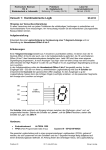
2.5 The bcd27seg function
Write a C function bcd27seg with the following prototype:
int bcd2seven(int inval)
The purpose of the function is to convert 4-bit binary code to 7-bit “seven-segment-code”.
The four least significant bits of the input value are to be converted into a 7-bit value, such
that this value can be sent directly to a seven-segment display to produce the appropriate digit.
in a C-function.
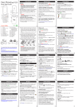
Recommended digit patterns are shown in the Figure below. To light up a segment of a sevensegment display digit, the corresponding bit should be zero (0). A one (1) will shut the
segment off.
bit index
0
5 6
1
4 3
2
2.6 The puthex function
Write a C function puthex with the following prototype:
void puthex (int inval)
The purpose of the function is to display the current time on the seven-segment digits
HEX3 through HEX0. The puthex function should call bcd27seg.
Add a call to the puthex function in your C-coded main loop.
The call to puthex function will be tested on the lab occasion, not in the simulator.
2.7 Parallel Input/Output, polling. Input using macros
The pollkey function
In the text above you can find which macro to use when you want to read values from
KEY3—KEY0.
Create a new project, called lab1IO, and copy all files from the previous project to this new
project.
Add a call to a pollkey function (see below) in your C-coded main loop.
Write the C-code of the function pollkey in the same file as the timeloc variable and the
mainprogram. This makes it possible for the pollkey function to reference the timeloc
variable.
Write a C function pollkey with the following prototype:
void pollkey()
that polls the keys and affect the behaviour of the time presentation.
Each time you push a button the behavior must change.
5
It is OK that your program expects you to release the button before you push another (or the
same) button and that you never push two buttons at the same time. (It is out of the scope of
this lab to take care of all possibilities but you are allowed to do it).
KEY0. Each time you push the button KEY0 the time must START counting.
KEY1. Each time you push the button KEY1 the time must STOP counting.
KEY2: Each time you push the button KEY2 the time value presented must be
incremented by one second.
KEY3: Each time you push the button KEY3 the time value must be set to 00:00.
You must use a flow chart (as shown in the recitations, and in lab 0) to describe the behavior
of the pollkey function.
You can find sample flow-charts in the exercise material and in the laboratory exercise 0
(delay is described by a flow chart).
Hints: You can use a variable RUN to indicate if the counting is ON or OFF and use this
variable to decide if tick is going to be called or not.
2.8 Response time
If you run the program above you will find that the response time when you push a
button might be disturbingly long. Probably also some button pushes are lost because
the pollkey function is called only once per second.
Modify your program so that the pollkey function is called once per millisecond. Make
sure that the time still will be incremented only once per second.
2.9 Timing by use of hardware timer and HAL-functions
Most processors offer possibilities to use hardware timer circuits. As the timer circuits are
clocked by a crystal oscillator the accuracy is in the order of 1 per million or even better.
In the Nios-II processor several timers are available.
Update your program to use a timer instead of using programmed delay.
It is possible to “order” a timer to “alarm” at some time in the future.
HAL-functions are supported to handle alarms of this kind.
The idea is that when the “alarm” expires, a special function, (alarm-handler) is (called and)
executed.
This function (the alarm handler) shall perform the actions wished (print time value) and
might also order if and when the same function shall be called again.
This is sometimes named “call-back”.
Create a new project called lab1timer and copy all files from the previous project to the
new project.
Modify the new project to use HAL-functions to order alarm once per second to print actual
time on terminal and hex-display. In the mainloop of the program, still continue to poll the
keys to keep the behaviour of the buttons.
You must write the alarm-handler function and use the HAL-function to initiate the system to
use it.
Information of these macros can be found in Software Developer’s Handbook in the starting
pages of chapter 5: Developing Programs Using the HAL, “Using Timer Devices”
6
2.10 I/O. Interrupt using HAL-functions
Refresh your memory concerning how to use interrupts in software and hardware, especially
in the Nios II CPU. Find out which HAL-functions to use to initiate and register interrupts in
Nios-II.
Information on HAL-functions can be found in:
Software Developer’s Handbook, chapter 7: Exception Handling.
In the previous program most of the CPU-time is spent polling the keys to detect changes.
Most of the (CPU-) time no changes occur and (valuable?) CPU-time is wasted.
It might be smarter to let the CPU work with something valuable (in this lab exercise:
calculating primes) instead of waiting for buttons to change.
The buttons have hardware support for interrupts. Information on this can be found in the
Nios II Embedded Peripherals Handbook, chapter 11: PIO Core with Avalon Interface.
Create a new project called lab1int and copy all files from the previous project to the new
project.
Modify the programs in your new project to use interrupt from the keys instead of polling the
keys. The main loop will now do nothing (idle-loop).
This means that you must write a Key_InterruptHandler for the Button PIO, and that
you must initialize the system so that interrupts from the Button PIO will cause the
Key_Interrupt_Handler function to be executed.
You must also enable interrupts from the Button PIO by writing appropriate value(s) to the
appropriate register(s) in the Button PIO using the appropriate macro(s).
Information of suitable HAL-functions can be found in:
Nios II Software Developer’s Handbook, chapter 7: Exception Handling.
The behavior depending on how you push the buttons must be changed a little from the
previous exercises:
KEY0. Each time you push the button KEY0 the time shall START or STOP counting.
KEY1: Each time you push the button KEY1 the time value presented must be
incremented by one.
KEY2: Each time you push the button KEY2 the the time value must be set to 00:00.
KEY3: Each time you push the button KEY3 the the time value must be set to 59:57.
2.11 I/O. Valuable background work calculating primes
At the last page of these instructions, you will find the function NextPrime. Its prototype is:
int NextPrime(int inval)
This function will return the smallest prime number bigger than inval. Calling NextPrime
with a value of 17 in inval will return the value 19, since this is the next larger prime. Calling
with the value 26 will return the value 29, and so on.
Update your program in previous project so that Prime Numbers are calculated by the
background program loop and printed on the console window at the “same time” as time is
shown on the HEX-displays (and LEDR:s). Make sure that time can still be manipulated by
the Keys, as specified above.
7
The function NextPrime will work on the DE2-board at the lab session.
To be able to run the NextPrime function in the NiosII Instruction Set
Simulator:
* right-click on the project folder,
* choose "System Library Properties",
* check the box "Emulate multiply and divide instructions",
* click "Apply"
If you forget to do this, the simulator may give an error message like:
"Break instruction called without debugger attached".
2.12 Configuration
In order to study the configuration used for the DE2-board, open the system.h file.
Answer the following questions.
1. Which Nios-processor is used in this configuration? Give the number of stages in the
processor pipeline.
2. The configuration contains a number of different memories. Order these memories
after typical access times and give the size of each memory.
3. Which I/O devices and timer devices are used in the tasks of Section 2? Give their
address spaces and IRQ-levels.
3 Laboratory tasks (performed at the laboratory session)
3.1 C and Assembler. “Show-time in the console window”
You must have passed Laboration 0. Bring up your program from Laboration 0.
Run your program from Laboration 0 on the Nios-II Hardware. When you connect the
DE2-board with a USB-cable to your laptop computer you may need to install a
USB-driver. This is described in Getting Started with Altera’s DE2 Board. Answer all
questions from the teacher.
C-code Show-Time completed, signed by Teacher: ……………………………….
3.2 Parallel I/O Output (on the LED and on the HEX-display)
Run your program from Section 2.4 on the Nios-board in the laboratory. Answer all
questions from the teacher.
Parallel I/O Output completed, signed by Teacher: ……………………………….
3.3 Parallel I/O Input (from the keys affecting the time value)
Run your programs from Section 2.7 and 2.8 on the Nios-board in the laboratory. Show the
flow-chart description of the pollkey function. Answer all questions from the teacher.
Parallel I/O Input completed, signed by Teacher: ……………………………….
8
3.4 Callback using Timer
Run your program from Section 2.9 on the Nios-board in the laboratory environment.
Answer all questions from the teacher.
Callback using Timer completed, signed by Teacher: ……………………………….
3.5 Interrupt generated by Keys using HAL-functions and
Primes
Run your program from Section 2.11 on the Nios-board in the laboratory environment.
Answer all questions from the teacher.
Interrupt using HAL-functions, signed by Teacher: ……………………………….
3.6 Surprise modification given by teacher
Surprise work to do, decided by Teacher: ……………………………….
Surprise work completed, signed by Teacher: ……………………………….
4 Examination
In order to pass the laboratory the student must:
• have completed all preparation tasks of Section 2 before the lab session.
• have answered all questions of Section 2.
• have completed all laboratory tasks of Section 3, and answered all questions from Teachers.
Name of Student: ……………………...……………………….
Laboratory exercise 1 completed, signed by Teacher: ……………………………….
References
[Alt-Intro] Altera Corporation. Introduction to the Altera Nios II Soft Processor
[Alt-HW] Altera Corporation. Nios II Processor Reference Handbook
[Alt-SW] Altera Corporation. Nios II Software Developer’s Handbook
[Alt-I/O]
Altera Corporation. Nios II Embedded Peripherals Handbook
[Alt-DE2] Altera Corporation. DE2 Development and Education Board. User Manual
9
NextPrime C-code
In the main loop, call NextPrime as follows:
next = NextPrime (next);
/* Produce a new prime. */
printf("\nNext Prime is %d",next);
The NextPrime function itself:
/*
* NextPrime
*
* Return the first prime number larger than the integer
* given as a parameter. The integer must be positive.
*/
#define PRIME_FALSE
0
/* Constant to help readability. */
#define PRIME_TRUE
1
/* Constant to help readability. */
int NextPrime( int inval )
{
int perhapsprime;
/* Holds a tentative prime while we check it.
*/
int testfactor;
/* Holds various factors for which we test
perhapsprime. */
int found;
/* Flag, false until we find a prime. */
if (inval < 3 )
/* Initial sanity check of parameter. */
{
if(inval <= 0) return(1); /* Return 1 for zero or negative input. */
if(inval == 1) return(2); /* Easy special case. */
if(inval == 2) return(3); /* Easy special case. */
}
else
{
/* Testing an even number for primeness is pointless, since
* all even numbers are divisible by 2. Therefore, we make sure
* that perhapsprime is larger than the parameter, and odd. */
perhapsprime = ( inval + 1 ) | 1 ;
}
/* While prime not found, loop. */
for( found = PRIME_FALSE; found != PRIME_TRUE; perhapsprime += 2 )
{
/* Check factors from 3 up to perhapsprime/2. */
for( testfactor = 3;
testfactor <= (perhapsprime >> 1);
testfactor += 1 )
{
found = PRIME_TRUE;
/* Assume we will find a prime. */
if( (perhapsprime % testfactor) == 0 )
{
/* If testfactor divides perhapsprime... */
found = PRIME_FALSE;
/* ...then, perhapsprime was non-prime. */
goto check_next_prime; /* Break the inner loop,
go test a new perhapsprime. */
}
}
check_next_prime:; /* This label is used to break the inner loop. */
if( found == PRIME_TRUE ) /* If the loop ended normally,
we found a prime. */
{
return( perhapsprime ); /* Return the prime we found. */
}
}
return( perhapsprime );
/* When the loop ends,
perhapsprime is a real prime. */
}
10