1
I
AMRCWEEo~kES
User’s
Manual
Table of Contents
Section
Contents
Psge
Introduction
1.1
1.2
The Projector .................................................................................................... 1-1
Purchaser’sRecordand Servicing....................................................................l.2
2
Installation &
Setup
2.1
2.2
2.3
2.4
2.5
2.6
2.7
2.8
2.9
2.10
2.11
2.12
Quick Setup.......................................................................................................2.l
InstallationConsiderations................................................................................2.2
HardwareSetup.................................................................................................2-7
Mounting.........................................................................................................2-11
Power Connection...........................................................................................2-14
Source Connections........................................................................................2.l4
Serial Port Connections...................................................................................2.l5
Optical Alignment...........................................................................................2-16
Source Setup ...................................................................................................2.24
Memory Setup.................................................................................................2.26
Image ShifterSemp.........................................................................................2.32
ACONSemp ...................................................................................................2.37
3
Operation
3.1
3.2
3.3
3.4
3.5
3.6
3.7
3.8
Overview...........................................................................................................3-1
Projector Basics................................................................................................3.l
Source Selection.............................................................................................3.lo
Setup Memories..............................................................................................3.l3
Display Adjustments.......................................................................................3.l5
ConvergenceRegis&ation...............................................................................3.25
Utility Fea~es ................................................................................................3.3l
Multiple.projectorFunctions..........................................................................3.47
4
Maintenance
4.1
4.2
4.3
Warningsand Guidelines..................................................................................4.l
Cleaning............................................................................................................4-2
Troubleshooting................................................................................................4.3
5
Specifications
5.1
Specifications....................................................................................................5.l
6
Appendices
A
B
c
D
E
F
G
F
Glossary...........................................................................................................A-1
Menu Tree .......................................................................................................B.l
ASR/ASILogic Diagrams................................................................................c.l
CommunicationCables....................................................................................D.l
KeypadReference............................................................................................ E-1
Throw DistanceTables.................................................................................... F-1
Lenses..............................................................................................................G.l
Intetiaces..........................................................................................................H.l
1
NOTE: Due to constant research, the information in this manual is subject to change without notice
54-017094-01
P (09/98) — SoftwareVersion4.2
...
Ill
I
I
Section
1
Introduction
1.1
The Projector
The Electrohome Marquee Ultra Series projectors are ultra high resolution
graphics projectors compatible with virtually all input sources. Their superior
performance and high quality projected images place them well above other
projection systems in their class. Features of the Marquee Ultra Series
include:
❑
❑
❑
❑
❑
❑
❑
❑
❑
❑
❑
•1
❑
Functional
Description
●
automatic lock to inputs between 14 kHz and 152 kHz
projected display size to 25 feet diagonal
liquid coupled (8500LC/9500LC models) or air coupled (8500) lens design
high brightness projection: from 225-240 ANSI lumens, depending on
model
high video bandwidth – 120 Mhz (-3dB)
multi-use full function keypad
intuitive menu driven, multi-language interface with on-line help
external computer control capability
superior geometry control, contrast, astigmatism and color performance
Contrast Modulation
ASR and AS1 to reduce the need for manual display adjustments
Image Shifter Module to help lengthen CRT life (standard on 9500LC)
optional ACON II automatic convergence feature
The projector accepts data/graphics and video input signals from a variety of
sources for projection onto flat, curved, or rear projection screens. System
inputs are processed to provide separate red, green, and blue image
components for projection through the projector’s three front lenses. The three
primary color components converge on the projection screen to provide a high
quality display output.
Sophisticated processor-based logic and control circuitry provide many of the
automatic features available on the Marquee Ultra. This circuitry interfaces
with the keypad to provide projector control by the user, such as:
❑
❑
❑
❑
❑
❑
turning the projector on or off
switching input sources
adjusting all display settings such as contrast, brightness, and size
correcting for display effects and input noise
displaying projector operating status screens and on-line help
controlling projector operating settings
Should projector servicing be required, service personnel can use the keypad to
make service adjustments and alignments. In some cases the projector may be
1-1
INTRODUCTION
serviced without accessing the projector’s internal circuitry.
Projector settings, usually different for different sources, are stored in memory
for each individual source. These settings me retained until changed by the
user, even if power is removed from the projector.
1.2
Construction
●
The projector body is comprised of a sturdy metal chassis, metal top covers,
and durable plastic side covers. The front top cover can be temporarily
removed to access the keypad and align the lenses. The rear top cover and
rear panel are removable for servicing and projector upgrading.
Expandability
●
Marquee
Purchaser’s
Record and
Servicing
Ultra Series projectors can be expanded or upgraded to include
additional features, accessories, and input options; these include a variety of
quick plug-in interface modules to suit the input devices you are using, a
signal switcher, a video decoder, a ceiling mount, and floor mount accessories.
For more information or if you need assistance for upgrading your projector,
contact your dealer or Electrohome.
Whether the projector is under warranty or the warranty has expired,
Electrohome’s extensive factory and dealer service network is always available.
Electrohome service technicians are filly trained to quickly diagnose and
correct projector malfunctions. Complete service manuals and updates are
available to service technicians for all new projector models manufactured by
Electrohome.
If you have a problem with your projector or require assistance, contact the
authorized Electrohome dealer from which the projector was purchased. Fill
out the information below for your records.
Purchaser’s
Record
Dealer:
Dealer Phone Number:
Projector Serial Number:
Purchase Date:
Note: Display projector seriaW by pressing El at presentation
Electrohome
Service
Electrohome Limited
809 Wellington Street North
Kitchener, Ontario
Canada N2G 4J6
Telephone (519) 744-7111
Toll-free in North America
1-800-265-2171
Fax: (519) 749-3136
level.
Locations
Electrohome
USA (1989), Inc.
9216 B@ court
Rancho Cucamonga
California 91730-5835
Telephone: (909) 466-3816
Toll-free: 1-800-333-3816
Fax: (909) 466-3824
Electrohome Europe Ltd.
ImagePoint
58 Suttons Park Avenue
Reading, Berkshire
RG6 1Az
UK
Tel: 01144-118-926-6300
Fax 01144-118-926-6322
Electrohome Asia PTE
Tannery Lane
+?03-05 Tannery House
Singapore 347790
Telephone (65) 7495525
Fax: (65) 7442900
1-2
.,_.... ... ..
Section
2
Installation & Setup
This section explains how to install and set up the projector. If you are familiar with the projector and want
to quickly set it up for temporary use, follow the Quick Setup instructions in section 2.1. For a complete
setup, skip section 2.1 and follow the instructions and guides covered in the remaining subsections.
2.1
Quick Setup
Step 1
Follow these 7 steps for quick set up of the projector:
●
Position
the Projector
To perform a quick setup, the projector must be positioned so that the throw
distance is the same as that used during the most recent optical alignment;
otherwise a detailed setup is required . The throw distance is the distance
between the center lens on the projector and the center of the projection
screen. See Appendix F and Appendix G for more information. Note: If an
optical lens alignment
Step 2
●
Connect
is required, refer to section 2.8, Optical Alignment.
the Power Cord
Plug the AC line cord into the line input unit on the lower front panel of the
projector. Plug the three prong end of the line cord in a grounded AC outlet.
Notes: 1) Input voltage must be between 90 VAC and 264 VAC. 2) Ensure the
line cord is the proper type for the AC receptacle.
Step 3
●
Connect
a Source
Connect a source to the projector’s built-in RGB input (slot 1) or, for the
9500LC Ultra, the Image Shifter RGB input (slot 2). Ensure the source is on
and properly connected.
Step 4
●
Access
the Keypad
Remove the projector’s front top cover to access the keypad. See page 3-2.
Step 5
●
Turn the Projector
On
Press on the keypad to turn the projector on. Hold down the power key
for about one second. Note: If the keypad has been configured for IR remote
operation, point it towards the screen or the front of the projector.
Step 6
●
Select the Input
Press [=1
!Zl~ to select the source connected to the built-in RGB input or,
if a 9500LC Ultra, press [~1
IF] @ to select the source connected to the
Image Shifter input.
Step 7
●
Adjust
the Display
Press [~1 [~1to select the Guided Source Setup tutorial.
2-1
. ...
I
“-””
& SETUP
INSTALLATION
2.2
Installation
Careful consideration should be given as to how and where the projection
system is installed. Although the projector offers high performance, the final
display quality could be compromised if the projector is not installed properly.
This subsection discusses the considerations you should make before
proceeding with a final installation. These considerations include the
installation type (floor, ceiling, rear), screen size and type, room lighting, and
ventilation.
Considerations
Installation
Type
●
Choose the installation type which suits your needs: front or rear screen, floor
mount or ceiling mount.
Front Screen, Floor Mount Installation
CONSIDERATIONS
ADVANTAGES
●
●
●
Easy to set-up.
Can be moved or changed
Easy to access projector.
●
quickly.
●
Shares floor space with audience.
May be accidentally moved, necessitating
alignment.
re-
Front Screen, Ceiling Mount Installation
CONSIDERATIONS
ADVANTAGES
●
●
●
Does not take up audience space.
The projector is less noticeable.
The projector cannot be accidentally
●
●
moved.
Installation is more permanent.
It is more difficult to physically access the
projector.
Rear Screen, Floor Mount Installation
ADVANTAGES
●
●
●
Projector is completely hidden from the
audience.
Easy to access projector.
Usually good ambient light rejection.
CONSIDERATIONS
●
Requires separate
room.
Rear Screen, Ceiling Mount Installation
ADVANTAGES
●
●
Projector is completely hidden from the
audience.
Usually good ambient light rejection.
CONSIDERATIONS
●
●
Requires separate room.
Installation cost is usually higher.
Rear Screen, Floor Mount With Mirror
ADVANTAGES
●
●
●
2-2
.,
Projector is completely hidden.
Usually good ambient light rejection.
Less space is required behind the screen
than other rear screen installations.
CONSIDERATIONS
●
●
Requires separate room.
Installation cost is usually higher.
-
INSTALLATION
Screen Type
●
& SETUP
Screen type is a very important factor when designing a projection system.
Inexperienced users or installers should always consult their dealer when
deciding on screen type. The following guidelines may be helpful to
understand the differences between screen types.
Front Screen Installations
There are two basic screen types: flat and curved. The choice between a flat
screen versus a curved screen is dependant on audience viewing angle and
screen gain. There is always a trade-off between viewing angle and gain.
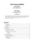
Viewing angles for both screen types are illustrated in Figures 2-1 and 2-2.
Flat screens offer a gain of about 1 with a viewing angle just less than 180°.
Incident light reflects equally in all directions so the audience can see the
display from various angles. Because of the lower gain, flat screens are more
effective when ambient lighting is reduced.
Figure 2-1. Audience
Figure 2-2. Audience
Coverage with Flat Screen
Coverage with Curved Screen
Curved screens have gains larger than 1 and viewing angles much less than
180°. Most curved screens have different horizontal and vertical viewing
angles. Incident light does not reflect equally in all directions. The reflected
light concentrates in a conical volume or “viewing cone”. Audiences within
the viewing cone see a brighter image than that from an equal area on a flat
screen. Audiences outside the viewing cone see a dimmer image.
2-3
.
..
I
INSTALLATION
& SETUP
To summarize, curved screens are better suited for brightly lit rooms where the
audience is situated within the viewing cone. Flat screens are best suited when
a wide viewing angle is required and ambient room lighting (near the screen)
is low.
Note: Screen Gain is defined in Appendix A, Glossaty.
Rear Screen Installations
There are two basic types of rear screens: diffised and optical. A diffused
screen has a surface which spreads the light striking it. Purely diffused screens
have a gain of less than 1. The main advantage of the diffused screen is its
wide viewing angle, similar to that of a flat screen for front screen projection.
Optical screens take light from the projector and redirect it to increase the light
intensity at the front of the screen. This reduces it in other areas. A viewing
cone, similar to that of a curved front screen installation, is created.
To summarize, optical screens are better suited for brightly lit rooms where the
audience is situated within the viewing cone. Diffused screens are best suited
when a wide viewing angle is required but there is low ambient room lighting.
Screen Size and
Throw Distance
●
Screen size and throw distance are interrelated. See Appendices F and G. As
screen size increases, the distance between the projector and the screen also
increases. During projection room design, make sure that the room can
accommodate the required position of the projector for the screen size you
need.
Screen Size
Screen sizes vary according to model and lens type. See Appendices F and G.
Choose a screen size which is appropriate for your application. If the projector
will be used to display text information it is important that the image size
allows the audience to clearly resolve all text. The eye usually sees a letter
clearly if eye-to-text distance is less than 150 times the height of the letter.
Small text, located too far from the eye, may not be legible at a distance even
though it is projected sharply and clearly on the screen.
To fill a screen with an image, the aspect ratio of the screen must be equal to
the aspect ratio of the image. The aspect ratio of an image is the ratio of its
width to its height. Standard video from a VCR has a 4:3 or 1.33:1 aspect
ratio. For example, to display a VCR output with a 4:3 aspect ratio onto a 10
foot (3m) high screen, the width of the screen must be at least 13.3 feet (4m).
Note: Screen size is ofien specified as diagonal size. Screens specified by,
diagonal size have aspect ratios of 4:3. Screens with other aspect ratios are
not typically specij7ed by diagonal size.
2-4
.
-.
..
I
—.
INSTALLATION
& SETUP
Throw Distance
The throw distance (projector-to-screen distance) must be determined for every
new installation. Throw distance, the distance between the projector’s center
lens and the center of the screen, is based on screen size. As screen size
increases, the distance between the projector and the screen increases. Make
sure that the room can accommodate the required position of the projector for
the chosen screen size.
Once your screen size is known you can determine the required throw distance
for your projector model and lens by using the formulas in Appendix G and
tables in Appendix F.
Notes: 1) Calculated values are for reference only. It is good practice to
simulate the setup to determine the necessary throw distance. 2) Display size is
aflected by input signal characteristics. Once the projector is set, use the Size
function to fine tune display size.
Throw distance and projection angle: Keep in mind that the ability to properly
focus all areas of the image is limited if a significantly tilted projector is too
close to the screen.
Lighting
●
Proper lighting is another important factor when designing a projection room.
Visiting a movie theatre can give you an idea of what makes a good projection
environment. All walls, floors and furnishings are dull colored and nonreflectively finished. Every effort should be made to create the best
environment for your system.
When designing a projection room, try to avoid white, reflective ceilings and
non-directional lighting such as fluorescent lights. The white ceiling spreads
the light which makes the room appear brighter. You want to keep the
lighting and reflections to a minimum. If it is not possible to keep fluorescent
lights off, consider using parabolic reflectors (“egg crates”) to direct light down
to the floor and away from the ceiling. Spot lighting (incandescent) is a better
way to obtain illumination. Installing light dimmers or rheostats allows you to
control your lighting environment.
Outside windows are undesirable in any projection environment. A small
crack between curtains on a sunny day can severely wash-out an image. Make
sure that curtains are opaque and fit snugly. Some curtains can provide up to
100 percent blockage of outside light. Pay close attention to the curtain
material facing inside the room. It should have a matte finish.
Even with no external light at all, reflections from room surfaces can degrade
the image. Light from the screen should be absorbed by surfaces so that it
will not be reflected back to the screen. Keep reflective surfaces to a
minimum.
2-5
I
INSTALLATION
& SETUP
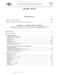
To minimize the effects caused by unwanted light from door and aisle ways,
carefully choose the position of your projector and screen. Figure 2-3 shows
an installation where poor screen placement has allowed too much unwanted
light to enter the screen. In Figure 2-4, the screen and the projector are
positioned so that unwanted light is minimized.
r
window
Figure 2-3. Poor Screen Placement
a
il
T
Q
o
0
-!
window
Figure 2-4.
Other
Considerations
●
Good Screen Placement
Here are some other considerations and tips which can help you improve the
design of your projection system.
❑
Proper ventilation is important. The ambient temperature should be kept
constant and below 35 “C (95 “F). Keep the projector away from heating
and/or air conditioning vents. Changes in temperature can cause drifts in
the projector circuitry which may affect performance.
❑
Keep the projector away from devices which radiate electromagnetic energy
such as motors and transformers. Common sources of these are slide
projectors, speakers, power amplifiers, elevators, etc. Keep 35 mm slide
projectors at least 2 feet away from the projector. Even if both are not used
at the same time, the magnetic fields created by the slide projector can
cause permanent magnetization of the projector.
2-6
,----- ..
I
INSTALLATION
& SETUP
IYFor rear screen applications, less space is required if a mirror is used to fold
the optical path.
❑
❑
Choose the right screen size for your application:
. As screen size increases, magnification increases which reduces
brightness. This reduces the contrast ratio which affects legibility. Sharp
defined edges become soft and fuzzy. Consider whether screen size is
more important.
. Installing a large screen in a small room is similar to watching television
close up; too large a screen can overpower a room. A good rule of
thumb is to be no closer than 1.5 times the width of the screen.
“ Larger screens require greater attention to lighting conditions.
When laying out your projection room, consider positioning the projector
and screen in a manner which will achieve maximum audience coverage and
space efficiency. For example, placing the screen along the larger wall in a
rectangular room will reduce audience coverage. Figure 2-5 shows two
examples of how audience coverage is maximized.
SQUARE ROOMS
Corner placement of screen
yields best audience coverage.
RECTANGULAR ROOMS
Screen placement along short
wall yields best audience coverage.
!
Figure 2-5. Screen Locations for Maximum
2.3
Hardware
Setup
Keypad
Conversion
Audience
Coverage
This section explains: how to convert the keypad from a built-in keypad to a
remote keypad, how to change keypad protocol and backlit settings, and how
to determine if reverse scan setup is required.
●
The projector includes a multi-use full-function keypad which may be
configured for use as a built-in, IR remote, or wired remote keypad. The
keypad is configured at the factory for built-in use. It is located below the
front top cover. You can use the keypad as it is or re-configure it for remote
operation. You can also “hard wire” the keypad to be a protocol A or
protocol B keypad (see section 3.7, Utility Features for information about
keypad protocols).
2-7
. .... . . .
. .-
.. —----_... —.------
INSTALLATION
& SETUP
Follow the steps below to convert the keypad to a remote keypad and change
its protocol setting.
Step 1
Unplug the projector then lift the
front top cover to access the builtin keypad. To lift the cover, grasp
it above the red and blue lenses
then lift it until the keypad is
exposed. The keypad is mounted
to a securing bracket located above
the lens assemblies. Loosen the
two bracket wing nuts then move
the keypad away from the bracket.
See Figure 2-6.
Step 2
Locate the battery compartment at
the back side of the keypad.
Squeeze the latch to open the door.
See Figure 2-7.
Battery
Compartment
Figure 2-6. Built-in Keypad Access
Cable
Connector
Figure 2-7. Battery Compartment
If converting the keypad to an IR remote, unplug the cable connector. Locate
the jumper wires next to the cable connector location. See Figure 2-8. The
jumper wires control the keypad’s operating settings.
.
a<.
~
‘i
~
JPZ ~
I
I
PROTOCOLA
PROTOCQL B
321
,—
,
(ALWAYS)
.. —
-,
,.”.
i
F-E&k-i
I JP4 I-”a
7 t
I
1~
IR REMOTE KEYPAD
I
I
L
Figure 2-8. Jwnper S@@S
2-8
\
I
INSTALLATION
& SETUP
JP1
This jumper setting is important if the keypad is configured for remote
operation. There are two keypad protocols: A and B. These protocols are
available to allow two projectors in the same room to be independently
controlled by separate remote keypads. The protocol setting of the keypad
must match that set in the projector’s Keypad Options menu ( [~ IZIEl ). For
more information about keypad protocols, refer to the Remote Control Options
entry in section 3.7, Utility Features.
JP2
This jumper must always be set between pins 1 and 2 as shown; otherwise, the
projector will not respond correctly to keypad commands.
JP3
This jumper must always be set between pins 1 and 2 as shown; otherwise, the
backlit feature will be disabled and the projector will not respond correctly to
keypad commands.
JP4
The JP4 jumper setting sets the keypad type. If you are converting the keypad
to an IR remote, move the JP4 jumper from between pins 2 and 3 to between
pins 1 and 2.
Step 3
For an IR remote keypad, place four AA size, 1.5V alkaline batteries in the
compartment ensuring that the +/- orientation of each battery is correct.
Position the compartment door into place.
For a wired remote keypad, an optional accessory cable (#03-001106-O2P) is
required. Plug the cable into the cable connector then position the door into
place. Plug the cable jack into the remote jack input on the projector.
WARNING:
OR WIRED
BAITERIES
Keypad Operating
Settings
>
DO NOT INSTALL BAl_fERIES IN THE KEYPAD IF A BUILT-IN
REMOTE CABLE 1S AITACHED
TO IT. THIS MAY CAUSE THE
TO EXPLOI)E.
keypad includes its own memory to store keypad operating settings. With
a few simple keystrokes you can over-ride the “hard wire” protocol setting
(explained earlier) and enable or disable the backlit feature. Keypad battery
life is increased if the backlit feature is disabled. The new operating settings
are stored in the keypad until the batteries are replaced (IR remote keypad) or
the keypad connection cable is unplugged (wired or built-in keypad).
The
2-9
.-
I
HWTALLATION
& SETUP
If the keypad is configured for IR remote operation, make sure the batteries are
installed. If it is configured for built-in or wired remote operation, make sure
its extension cable is properly connected to the projector. Perform the
following keystroke sequences to change its operating settings:
“ To toggle the keypad’s protocol setting (A or B),
press W [~1 1~1 =
U.
s To toggle the backlit feature (enable or disable),
press @ [-l [~ IZ@El~.
“ To return all configuration settings to the jumper settings,
press ~ [~1 1~1 =
(Z1.
Note: The projector will not respond to keypad commands if you press
If pressed accidentally, press @ m
~
=
Qmmm@.
clear all keystroke settings.
Reverse Scan
●
❑ to
If the projector is not installed in a front screen, floor mount configuration,
reverse scan setup may be required. Reverse scan setup must be performed by
a qualified Electrohome service technician. Refer to Table 2-2 to determine if
reverse scan setup is required. Contact your dealer for assistance.
Table 2-2.
Operating
OPERATINGCONFIGURATION
~~
~w
Front Screen,
Floor Mount
(default configuration)
Configurations
HORIZONTAL
SCAN
VERTICAL
SCAN
NORMAL
NORMAL
Front Screen,
Ceiling Mount
REVERSED
REVERSED
Rear Screen,
Floor Mount
REVERSED
NORMAL
Rear Screen,
Ceiling Mount
NORMAL
kh
~v
REVERSED
Rear Screen,
I%P
2-10
-. ......
Floor Mount,
With Mirror
NORMAL
NORMAL
I
INSTALLATION
2.4
Mounting
Front Screen
Installations
& SETUP
The projector should be mounted after the system design has been established
and reverse scan setup (if required) is complete.
●
Floor Mount
Mount the projector on a secured table or cart. Position the projector at the
chosen room location with the projector pointing towards the center of the
projection screen. The angle of projection, combined with the tilt angle of the
screen should direct the reflected image towards the center of the audience. It
is recommended that the difference between the projection angle and the
screen tilt angle (within a common reference) be less than 15°. Refer to
Figure 2-9.
Screen
lilt
Projector lilt - Screen TM= &
8S15”(recommended)
\
Figure 2-9. Floor Mount Installation
You can adjust projection angle and level by adjusting the height of the
projector legs. See Figure 2-10.
\
0
---+
Figure 2-10.
Leg Adjustment
2-11
-r
,.-.
.—,.
.
I
INSTALLATION
& SETUP
Ceiling Mount
Mounting the projector to the ceiling requires the use of a projector ceiling
mount fixture. The fixture is shipped from the factory in kit form (with
assembly instructions) for assembly and installation by the dealer/installer. For
more information, contact your dealer or Electrohome.
Position the projector so that it is pointing toward the center of the projection
screen. The angle of projection combined with the tilt angle of the screen
should direct the reflected image towards the center of the audience. It is
recommended that the difference between the projection angle and the screen
tilt angle (within a common reference) be less than 15°. See to Figure 2-11.
---tsL_
. . ..-_-.l---,:.
Projector Tlt
8 ~~_
Eye
8
Level
)
Projector ~lt - Screen lilt= 9
051 5“(recommended)
I .&-.
I
Figure 2-11.
Screen
Tlt
Ceiling Mount Installation
Instructions for adjusting projection angle are provided with the fixture kit.
For more information, contact your dealer or Electrohome.
Rear Screen
Installations
●
When installing a rear screen system, the vertical positioning of the projector
is dependant on the type of rear screen being used. There are two basic types
of rear screens: optical and difi%sed.
Optical Rear Screen Systems
If the system includes an optical rear screen, mount the projector along the
center axis of the screen as shown in Figure 2-12.
Projection Angle = O“
Figure 2-12.
2-12
,., .
. . ...
7
Optical Rear Screen Installation
INSTALLATION
Diffused
& SETUP
Rear Screen Systems
If the system includes a diffised rear screen, floor mount or ceiling mount the
projector so that the image is directed to the center of the audience. Projection
tilt should be less than 15°. See Figure 2-13.
-. . . . ..rz.-.--$.
Ia
-
A_-.-.-.: -
-
Projector Tilt
~e
Level
%
0
Projectur Tit - Saeen lilt =0
8s15“ (recommended)
Figure 2-13.
Diffused Rear Screen Installation
In situations where the space behind the projector is limited, a mirror may be
used to fold the optical path as illustrated in Figure 2-14. If a diffused screen
is used, the projection angle 0 should be less than 15°. If an optical screen is
used, the optical path between the mirror and the screen should be perpendicular to the screen. Much attention must be given to the positioning of the
projector and the mirror. This can be quite difficult for installers unfamiliar
with this type of installation. It is recommended that your dealer or an
experienced installer perform the installation.
Note: When using a mirror as shown in Figure 2-14, the calculated
distance (D) is the summation of D1 and D2.
Projector to Screen Distance (D)= (DI +D2)
Mirror llt
=~+
throw
1/2 Projection lilt
\
D1
Minimum Mirror Size = ~ x Screen Siz6
Surface Mirror
8<15
\
(recommended)
t
~
Projector Tilt
Projector Tlt -~
2
Figure 2-14. Folded Optics
2-13
I
INSTALLATION
2.5
& SETUP
Power
Connection
To apply power to the projector,
plug the AC line cord into the
line input socket located at the
front panel of the projector. Plug
the three prong end of the line
cord in a grounded AC outlet.
Input voltage to the projector
must be between 90 and 264
VAC, 50 or 60 Hz. The power
source must supply 650 watts of
power to the projector.
———. =
—
90-264 VAC
Figure 2-15.
2.6
Source
Connections
Power Connection
The projector includes a built-in RGB input interface for connection of
external RGB sources and audio equipment. This input interface is shown in
Figure 2-16. The built-in interface is not removable.
(l #
.
, h
lull
~
..”=*
u
“*,~
.
+i23 !&S-e&%”
“
“ “6600-0$’
T
Slot
Figure 2-16.
2
“Slots”3 to 6 when
optional decoder
is insta//ed.
t’slot 1
Projector Input Slots
Optional interface modules are available to accommodate other signal types.
These include a Composite/S-Video Module, an HDTV Input Module, and a
PC Analog Input Module. Any one of these can be installed in slot 2. A
Marquee Multi-Standard Decoder may be installed to add four additiomd
inputs to the system (“slots” 3 to 6). To further increase the number of inputs,
a signal switcher may be connected to the RGB interface in slot 1 to add 8
more sources to the system (9 switcher inputs replace one RGB input). Other
switchers may be connected to the first switcher for more inputs. Brief
descriptions of the above mentioned optional modules are given in Appendix
H, Interjizces. For additional details, contact your dealer and Electrohome.
2-14
I
INSTALLATION
& SETUP
The two RGB interfaces provided allow connection of an RGB source having
one of the following sync types: sync on green, composite sync, or separate H
& V sync. To comect a source, connect the red, green, and blue outputs to
the RED, GREEN, and BLUE inputs on the interface. If the souce uses sync
on green, no additional cables are required. If the source provides a composite
sync output, connect it to the HOIUCOMP input. If the source provides
separate horizontal and vertical sync outputs, connect the horizontal sync
signal to the HORfCOMP input, and connect the vertical sync input to the
VERT inuut. Interconnection cables must be terminated with BNC connectors.
Figure 2-~7 show source connections for the built-in interface.
Ill
[t! t
‘@@’
=!&
@65‘@@’”
IN —AlmO-OuT
-
BNC
connectors
RGR
and
phono
plugs
~ync
Irom
~urce
w
Q
Lefi and Right Audio Inputs (preamplifier)
*J
Left and Right Audio Outputs to Amplifier
Figure 2-17.
Built-in RGB Interface
Connections
To control audio levels in an audio/visual system, pre-amplified (line level)
audio inputs are connected to the left and right channel audio inputs on the
interfaces. Audio outputs from the built-in interface are then connected to
external audio amplification equipment for sound output. All audio connection
cables require standard RCA type phono plugs.
2.7
Serial
Port
Serial port connections are required when:
❑
using a Marquee
Signal switcher
with the projector or
❑
the projector is to be controlled by a computer/controller.
Connections
The projector’s serial ports are located on the back panel. See Figure 2-18.
u
I
\ [
Figure 2-18.
Serial Port Connections
2-15
..
..
INSTALLATION
& SETUP
If using the projector with a Marquee signal switcher, connect an RS-232
serial communication cable between the switcher and the projector serial port
labelled “SWITCHER”. If the projector is to be controlled by a computer or
controller which has an RS-232 serial port, connect an RS-232 serial cable
between the computer and the projector serial port labelled “IN”. After the
connection is made, set the serial port baud rate as described in the Projector
Setup entry in section 3.7, Utilities.
Notes: 1) All serial connections require a 9 pin D connector at the projector
end. Refer to Appendix D for cable wiring requirements.
2) For
computerlcontroiler
control, PC sojiware is required. 3) The RS-232 serial
port labelled “OUT” is provided for projector networking applications.
2.8
Optical
Alignment
Optical alignment is required when the throw distance changes or the projector
cannot be focused using the focus controls. The projector is optically aligned
at the factory at a fixed screen size and a fixed projector-to-screen distance.
See Appendices F and G for the specific details needed for your projector
model and lens. If the throw distance has changed since the last setup, proceed
as follows:
Notes: 1) The projector must be warmed up for at least 45 minutes prior to
peq%orming optical alignment. 2) Optical alignment is both a mechanical and
electrical adjustment.
Electrical adjustments are stored in the current setup
memory. After alignment is complete, setup memories which were previously
set up (if any) must be set up again. Memory setup is explained in
section 2.10. 3) Factory alignment is pe~ormed using the internal crosshatch
with a 61.8 kHz signal applied.
It is recommended that optical alignment be performed using the projector’s
Guided Mechanical Setup tutorial. This tutorial displays step-by-step
instructions during the alignment. The instructions in this section require use
of the Guided Me~hanical_Setup tutorial.
To access and use the Guided
==
Mechanical Setup tutorial, turn on the
projector ( ) then press ~
at
presentation level. The Help menu is
displayed. Next press H to select
Guided Mechanical Setup. The first
page of the guide will be displayed
on the projection screen. When using
the guide, press ~
to display the
next page, press W
to display the
previous page. When complete, press EXZl
to end Help.
1.
Guided
Source
Setup
2. Guided
Mechanical
3. Source
Selection
4. Keypad
Guide
5.
-
6.
Using
Help
all
menus:
For
Press
then
a number
<ENTER>
Setup
Guide
or use A~
to select
item.
~
Ste9.- 1 b
2-16
.
If you have not already done so,
calculate the throw distance and set the projector position as explained in
section 2.4, Mounting. Turn power off before moving the projector.
I
INSTALLATION
Step 2
●
& SETUP
Locate the front top
cover of the projector.
See Figure 2-19. Next,
position your hands
above the red and blue
lenses then grasp the
cover. Gently lift it until
it is released from its
securing latch. Slide the
cover away from the
projector as shown in
Figure 2-20 below.
Figure 2-19.
a) Lift front cover until
latch is released.
r
Figure 2-20.
Front Top Cover
b) Slide cover forward.
%
Front Top Cover Removal
Also remove the black decorative foam piece at the front of the lenses
(removal is optional). Remove the large allen head driver from the tool kit
provided with the projector. The driver is used for lens alignment.
Examine the lenses and hardware as shown in Figure 2-21a (or, for the 8500
model, see Figure 2-21b). Each lens consists of a rear section and a front
section. The rear section sets the optical focus at the center of the image and is
secured to the lens body by a wing nut at the top rear of the lens assembly.
The front section sets the focus at the corners and is secured to the rear section
by a wing nut at the top front of the lens assembly.
‘op’’a’e~
Securing Bolts
Center
Focus Adjust
Comer
Focus Adjust
*
“*
Blue
Figure 2-21a.
8500LC/9500LC
Green
Lens Assemblies
w
Red
- Top View
2-17
. .. .. ... . .
.-
I
INSTALLATION
& SETUP
Lens/CRT ‘“pp’a’e~
SeCuring Boits
Center
Focus Adjust
II
‘*11*11*1”
‘“’’+WW*M*V
Focus Adjust
~~~
Blue
Figure 2-21b.
8500 hns
Green
Assemblies
Red
- Top View
For the 8500LC/9500LC: The lenses are secured to the projector frame by a
top plate and individual mounting plates as shown in Figures 2-21a and 2-22a.
During optical alignment, adjust the top plate securing bolts using the ball nose
) supplied with the projector. Adjust the
screw driver ( ~
mounting plate securing bolts using either the ball nose screwdriver or the
) supplied, as necessary. The securing bolts
projector wrench ( ~_~~a
are labelled B-C-D.
Figure 2-22a.
8500LC/9500LC
Lens Assemblies
- Front View
For the 8500: The lenses are secured to the projector frame by a top plate as
shown. During optical alignment, adjust the securing bolts as instructed--refer
to Figures 2-21b and 2-22b. The securing bolts are labeled A-B-C-D.
2-18
I
INSTALLATION
Lens Mounting Plate
\
Blue
Green
& SETUP
Red
Fo&Js Adjust
Left/Right
Focus Adjust
Factory/Service
Adjust Only
Figure 2-22b.
8500 Las
Assemblies
- Front View
For the 8500LC/9500LC, each CRT is attached to its lens by socket head allen
screws located at each lens mounting plate. For each lens, the upper left
screws (when facing the lens) adjust the focus between the left and right sides
of the picture, and the upper right screws adjust the focus between the top and
bottom of the picture. Use the supplied ball nose screw driver for these
adjustments.
For the 8500, each CRT is attached to its lens by 3 socket head allen screws
located at each lens mounting plate. For each lens, the upper right screw
(when facing the lens) adjusts the focus between the top and bottom of the
picture, and the lower left screw adjusts the focus between the left and right
sides of the picture. See Figure 2-22b.
Step3
●
Loosen the rear wing nut on the green lens. Rotate the lens
using the wing nut until the picture is focused in the center.
Tighten the rear wing nut.
BGR
Step4
●
Loosen the front wing nut on the green lens. Rotate the front
lens barrel until the picture is focused in the comers. Tighten
the front wing nut.
Step5
●
Steps 6 to 8 require that you look directly into the lenses for adjustment.
Before you continue, press ll!l to reduce contrast to a low level (less than 10%).
WARNING:
DO NOT LOOK INTO THE LENSES
NORMAL VIEWING LEVEL.
. . . ..0
IF CONTRAST IS SET TO
Step6
●
Look directly into the red lens. Press g, !Zl,@ or@ to center the displayed
crosshatch on the face of the picture tube.
Step7
●
Look directly into the green lens. Press Q, m, Ill or @lto center the displayed
crosshatch on the face of the picture tube.
Step8
●
Look directly into the blue lens. Press ~, m, m or ~ to center the displayed
crosshatch on the face of the picture tube.
2-19
INSTALLATION
& SETUP
Step 9
●
Press ~ to increase contrast to a normal viewing level.
Step 10
●
Pivot the projector and
move it side to side as
I
necessary to display a
pivot
point
symmetrical crosshatch
centered left-to-right on the +
. . . 0.0
( &
screen. The pivot point
-?**
should be at the rear wing
nut of the green lens to
avoid changing the throw distance.
Step 77
Step 12
●
●
Tilt the projector until the
center horizontal line is
level and centered with the
screen . Adjust the feet of
the projector or ceiling
mount as required.
\
+
2
a“o
After
Before
BGR
c [m>
u
u-
B“B
Before
A red image is displayed. Loosen the rear wing nut on the
red lens. Rotate the lens using the wing nut until the picture
is focused in the center. Tighten the rear wing nut.
Step 13
●
Loosen the front wing nut on the red lens. Rotate the front
lens barrel until the picture is focused in the comers. Tighten
the front wing nut.
Step 14
●
A blue image is displayed. Loosen the rear wing nut on the
blue lens. Rotate the lens using the wing nut until the picture
is focused in the center. Tighten the rear wing nut.
After
BGR
BGR
Step 15
●
Loosen the front wing nut on the blue lens. Rotate the front
lens barrel until the picture is focused in the comers. Tighten
the front wing nut.
Step 16
●
Press Q or ~ to adjust for best electrical focus at the center of the picture.
Step 17
●
On the 8500LC/9500LC, loosen the three bolts
labelled “B”. One is located on the top plate.
The other two are below the red lens.
BGR
On the 8500, loosen the four bolts labelled
“A”.
Loosen the two bolts labeled “B”.
Step 18
●
A red and green crosshatch is displayed. Move the
red lens so that the leil and right edges of the red
crosshatch match the green.
Before
2-20
After
I
INSTALLATION
Step 79 >
& SETUP
On the 8500LC/9500LC, tighten the three bolts
labelled “B”.
On the 8500, tighten the two
bolts labeled “B”.
—
■
&
BGR
BGR
Step 20
●
On the 8500LC/9500LC, loosen the three bolts
Iabelled “D”. One is located on the top plate.
The other two are below the blue lens.
BGR
On the 8500, loosen the two bolts labeled “D”.
BGR
Step 21
Step 22
●
●
A blue and green crosshatch is displayed. Move the
blue lens so that the left and right edges of the blue
crosshatch match the green.
m-m
After
Before
On the 8500LC/9500LC, tighten the three bolts
labelled “D”.
BGR
On the 8500, tighten the two bolts labelled “D”.
BGR
Step 23
●
A green image is displayed. Loosen the rear wing nut on the
green lens and slightly defocus the center of the picture.
BGR
Step 24
●
TOP Bolt
On the 8500LC/9500LC, locate
.
the two adjustment bolts at the
+y:l~
upper right comer of the green
lens mounting plate (viewed
[m]+[m]
from the front). Adjust the two
After
Before
bolts until the top and bottom
areas of the pic~re are equally defocused. Use the following technique for the
adjustment: Turn the SIDE bolt 1/8 turn CCW. Turn the TOP bolt about 1/8
turn CW until it stops. If defocus at the top and bottom are equalizing, repeat
until equal. If the top and bottom are not becoming equally defocused, use the
same technique but instead turn the TOP bolt CCW then turn the SIDE bolt
CW until it stops. Repeat until defocus is equal.
On the 8500, adjust the large allen head bolt located at the upper right comer
of the green lens mounting plate. Turn the bolt head until the top and bottom
2“21
I
INSTALLATION
& SETUP
d
areas of the picture are equally
defocused.
n+[~~
NOTE: On all models, it muy
w
P
be necessary to readjust the
lens’ rear wing nut to keep the center defocused.
Step 25
●
-
After
Rotate the green lens using the rear wing nut until the picture
is focused in the center. Tighten the rear wing nut.
BGR
If necessary, loosen the front wing nut, rotate the front lens
barrel to readjust the focus in the comers, then re-tighten the wing nut.
Step 26
●
A red image is displayed. Loosen the rear wing nut on the
red lens and slightly defocus the center of the picture.
Step 27
●
TOP Bolt
On the “LC”
.
models, locate
+,::
[~]+[r~
the two
adjustment
bolts at the
After
Before
upper right
c~rner o; the red lens mounting plate (viewed from the front).
BGR
Adjust the two bolts until the top and bottom areas of the picture are equally
defocused. Use the same technique as that used for the green adjustment
(step 24).
On the 8500, adjust the large
allen head bolt located at the
[m]”[n]
upper right comer of the red
After
Before
lens mounting plate. Turn the
bolt head until the top and bottom areas of the picture are equally defocused.
Note: On all models, it may be necessary to readjust the lens’ rear wing nut to
keep the center defocused.
Step 28
●
On the 8500LC/9500LC, locate
the two adjustment bolts at the
upper left comer of the red lens
mounting plate (viewed from
the front).
TOP Bolt
SIDE
Bolt ~
[m]”[n]
Before
After
Adjust the two bolts until the left and right areas of the picture are equally
defocused. Use the same technique as that used for the previous adjustment
(step 27).
On the 8500, adjust the large
allen head bolt located at the
lower left comer of the red
lens mounting date. Turn the
2-22
... .
[~[]+[~]
Before
After
—,
INSTALLATION
& SETUP
bolt head until the left and right sides of the picture are equally defocused.
Note: On all models, it may be necessary to readjust the lens’ rear wing nut to
keep the center defocused.
Step 29
●
Rotate the red lens using the rear wing nut until the picture is focused in the
center. Tighten the rear wing nut. If necessary, loosen the front wing nut,
rotate the front lens barrel to readjust the focus in the comers, then re-tighten
the wing nut.
Step 30
●
A blue image is displayed. Loosen the rear wing nut on the
blue lens and slightly defocus the center of the picture.
BGR
Step 31
●
On the 8500LC/9500LC, locate
the two adjustment bolts at the
upper right comer of the blue
lens mounting plate (viewed
from the front).
TOP Bolt
.
+~:1~
[m]”[n]
Before
After
Adjust the two bolts until the top and bottom areas of the picture are equally
defocused. Use the same technique as that used for the green and red
adjustments.
On the 8500, adjust the large
allen head bolt located at the
[n]”[n]
upper right comer of the blue
After
Before
lens mounting plate. Turn the
bolt head until the top and bottom sides of the picture are equally defocused.
Note: On all models, it may be necessary to readjust the lens’ rear wing nut to
keep the center defocused.
Step 32
●
On the 8500LC/9500LC, locate
the two adjustment bolts at the
upper left comer of the blue
lens mounting plate (viewed
from the front).
TOP Bolt
SIDE
Bolt ~
[n]”[Q]
Before
After
Adjust the two bolts until the left and right areas of the picture are equally
defocused. Use the same technique as that used for the previous adjustment
(step 31).
On the 8500, adjust the large
allen head bolt located at the
@@l@j
[rfl+[nl
lower left comer of the blue
Before
After
lens mounting plate. Turn the
bolt head until the left and right sides of the picture are equally defocused.
2-23
.
INSTALLATION
& SETUP
Note: On all models, it may be necessary to readjust the lens’ rear wing nut to
keep the center defocused.
Step 33
●
Rotate the blue lens using the rear wing nut until the picture is focused in the
center. Tighten the rear wing nut.
If necessary, loosen the front wing nut, rotate the front lens barrel to readjust
the focus in the comers, then re-tighten the wing nut. See Step 15.
Step 34
●
For the 8500LC/9500LC, optical alignment is now complete. If you had
removed the foam insert, reinstall it now. Install the front top cover. Proceed
to set up each source by following the source setup procedure in section 2.9,
Source Setup.
On the 8500, tighten the bolts labeled “A”. Optical alignment
is now complete. If you had removed the foam insert,
reinstall it now. Install the front top cover. Proceed to set up
each source by following the source setup procedure in
section 2.9, Source Setup.
2.9
Source Setup
BGR
This section gives step-by-step instructions for quick setup of the projector for
a selected external source. For a complete setup, repeat these steps as required
for each source connected to the projector.
Before starting, ensure that the projector is optically and mechanically aligned.
If optical alignment is required, follow the setup instructions in section 2.8,
Optical Alignment.
Select the source to be set up using the Source command
and make sure it is visible on the projection screen.
To make setup easier, it is
mv
recornmended that you use the
projector’s Guided Source Setup
1. Guided Source Setup
‘mtorial. It provides source setup
Setup
2. Guided Mechanical
instructions on screen to guide you
Selection
Guide
3. Source
Guide
4. Keypad
through the adjustments. To access
5.
the tutorial, first press ~
at
6. Using Help
presentation level. The Help menu is
For all menus:
displayed. Next press a to select
Press a number
or use 4Q
Guided Source Setup. The first page
then <ENTER>
to select- f~~m-- .
I <HELP> for assistanceof the guide will be displayed on the
<RECALL>
to go back one level
projec~on screen. Wh~n using the
<EXIT> to return to picture
guide, press @ to display the next
page, press to display the
previous page. When complete, press @@.
I
I
Step 1
2-24
..
..
●
Press @@ then ~ or m to increase or decrease the brightness setting until
black areas in the image just disappear.
I
INSTALLATION
❑ to adjust the contrast of the image to a suitable level.
Step 2
●
Press w
Step 3
●
Press g or El to adjust electrical focus for best overall sharpness.
Step 4
●
Press ❑ or Ill to adjust skew until the vertical line
through the center of the image is not tilted
(perpendicular to the horizontal line). Press lZl or E
until the center horizontal line is perpendicular to
the vertical.
then ~ or
& SETUP
[+]”[+]
Before
After
[T]”[T]
Before
Step 5
Step 6
Step 7
●
●
●
After
Press @ or Ill to adjust keystone until the width at
the top of the picture is equal to the width at the
bottom.
[n]”[m]
Press @ or ❑ to adjust side pincushion until the left
and right sides of the picture are straight and not
curved.
[n]”[m]
Press a or m to adjust vertical bow until the
horizontal line at the middle of the picture is
straight. Press @lor Ill to adjust horizontal bow so
that the vertical line at the middle of the picture is
straight.
Before
Before
After
After
l==l+r’_l
L.-..JLJ
Before
After
a“ ~
After
Step 8
●
Press ~ or m to adjust top pincushion until the
horizontal line at the top of the picture is straight
and not curved. Press ❑ or a to adjust top
keystone so that the top edge is level.
Step 9
●
Press a or@ to adjust bottom pincushion until the
horizontal line at the bottom of the picture is
straight and not curved. Press Ill or @ to adjust
bottom keystone so that the bottom edge is level.
[DD1
[m]”[m]
Before
After
Before
After
2-25
.
——
INSTALLATION
& SETUP
Step 70
●
Adjust C linearity as follows:
Press D or@ until the horizontal line through the
center of the crosshatch is equally distant from the
lines at the very top and bottom.
,’
\
J
After
Before
Press Ill or@ until the center of the crosshatch is
equally distant from the vertical lines at the left and
right edges.
\
f
+
,
\
Before
Step 71
●
Adjust S linearity as follows:
\
J
L
&
After
J
m+m
Press B or lZl until the height of each crosshatch
square is equal from the top to the bottom.
Before
After
Press a or@ until the width of each crosshatch
square is equal from the left to the right.
The source connected to the currently selected input should now be visible. If
there is no picture, check to see if the source is active.
Step 12
●
Press El, ~, ~ or Ill to adjust phase until the
picture is centered on the screen.
a“~
Step 13
Step 14
●
●
Press ~, ❑, m or m to adjust the size of the
picture. Ensure that objects in your picture have the
correct shape. For example, if there is a circle in
your picture, size should ‘be adjusted until the circle
is round, not oval.
The final step is convergence. If the projector
includes the ACON option, press ~ =
u to
exit the guide and alIow ACON to converge the
system. Otherwise, press (ml 1~1 ~1 to enter
Guided Convergence.
Reminder: Remember that all of the adjustments
other sources in the system.
2.10
Memory
Setup
After
[n]”[n]
Before
After
-+
ma
Before
After
above should be repeated for
This section explains how to set up projector memories to improve the
performance of the projector’s ASI and ASR features. If you are not farniIiar
with setup memories, read section 3, Operation, prior to memory setup; in
particular, read section 3.4, Setup Memories, and the ASI with Save and Turn
ASR OnlOff entries in section 3.7, Utility Features. If the projector’s setup
memories are properly set up, the projector will be easier to use and operate.
2-26
.
..—
-.
INSTALLATION
& SETUP
Note: Memory setup should be pe~ormed when the projector is in its jlnal
operating position. If the physical position of the projector changes, memory
setup must be repeated.
Here is a brief summary of the setup memory, ASR, and ASI discussions in
Section 3.
About Setup Memories
...
The projector has 80 setup memories for storing display settings of different
sources. Multiple setup memories are required since display settings usually
vary amongst sources. There are two types of setup memories: Input and
Recall. Both memory types store the same parameters. The only difference is
that Input memories store display settings for a particular physical input (e.g.,
switcher O, slot 1) while Recall memories can be used with any input.
At any one time, one setup memory is the current setup memory. The display
settings in the current setup memory are used for the current display. When a
source is selected by entering its input number, the Input memory for the
selected input becomes the current setup memory*. If a Recall memory is
selected, it becomes the current setup memory*. Display adjustments are
automatically saved in the setup memory which is current at the time of
adjustment (unless the setup memory is locked).
* Note: If the ASR feature (explained below) is turned on during setup memoty
selection, the selected memory may not be the current setup memory.
To display the Recall memories stored in the projector, press @l ~J. Press
@l ~ to display the Input memofies. (Unused setup memofies Me not
displayed).
About ASI and ASR ...
ASI (Automatic Source Interpolation) is a feature which automatically adjusts
display settings based on the settings of other setup memories stored in the
projector. When a setup memory is first created, ASI automatically generates
its initial display settings. These settings will be created by copying another
setup memory or by interpolating multiple setup memories.
ASI is activated when:
. A new setup memory is created.
“ An ASR is performed and its logic has activated an ASI.
. An “ASI with Save” is specified by the user (see section 3.7).
ASR (Automatic Source Recall) is a feature which, when turned on for a given
input, provides automatic Recall memory selection or ASI adjustment. ASR
processing can activate when: 1) a change in scan frequencies is detected at
the input, 2) an input is selected, 3) a Recall memory is selected, or 4) a
channel is selected. This feature is primarily intended for use when many
different sources must share the same input (via a third party switcher, for
example) or when a signal source can output several different scan frequencies
2-27
.
I
INSTALLATION
& SETUP
(e.g., a SVGA card). When a source switch is made, the projector may
automatically select a Recall memory with matching scan frequencies or create
the display settings based on the settings in other setup memories.
(Refer to Appendix C for ASI/ASR logic diagrams.)
Input Memory Setup
●
Follow these steps to prepare an Input memory for a source.
Note: To assure proper setup of an existing Input memory, ASR must be off
(default) for the memory.
Step 1
Comect the source to the input to be set up, then select the input using the
Source command. For example, if the source is connected to slot 1 of the
projector, press =
IQ]Q. If the Input memory did not previously exist, it
will be created automatically.
Step 2
The source should be displayed on the projection screen. If much adjustment
is required, press @l El lZl to perform ~ ASZwith Save. me display
appearance may improve based on the settings stored in other setup memories.
(If the Input memory is new, ASI with Save will have already been performed
when the input was selected.)
Step 3
Make display adjustments as required. Adjustment changes will automatically
be saved in the Input memory.
Recall Memory
Setup
●
Follow these steps to prepare a Recall memory.
Step 1
Select the input connected to the source. For example, if the source is
connected to switcher 1, slot 5, press [ml
IF] El. The source should be
displayed on the projection screen.
Note: To assure proper setup of a Recall memory, ASR must be of (default)
for the current input.
Step 2
Select a Recall memory as the current setup memory. For example, to make
Recall memory 03 the current setup memory, press (=
IZI@. If the Recall
memory did not previously exist, it will be created automatically.
Step 3
If much adjustment is required, press (fil IT]@lto perform an “ASI with
Save”. (If the Recall memory is new, ASI with Save will have already been
performed when the memory was selected.)
2-28
.
\
I
INSTALLATION
Step 4
Make display adjustments as required. Adjustment changes will automatically
be saved in the Recall memory.
ASI Improvement
●
If the projector will be used with many sources, or new sources will be
frequently added to the system, it is recommended that five or six setup
memories be created expressly for the purpose of improving ASI accuracy.
ASI accuracy improves as more setup memories are created and stored, and the
variations amongst horizontal and vertical scan frequencies increases. For
example, if you always use the same input and you never use Recall memories
(thus only one setup memory has ever been created), ASI will not be effective.
However, if many Input and Recall memories have been used and adjusted for
a variety of sources, the projector has more “knowledge” in its database for
performing an ASI. As this “knowledge” increases, ASI accuracy improves.
An easy way to add setup memories at various scan frequencies is to use the
projector’s internal frequency generator. The internal frequency generator can
display a test pattern using the scan frequencies you select. When display
adjustments are made, the display settings are stored in the current setup
memory. Prepare a Recall memory using the generator as follows:
Step 1
Select a Recall memory to be the current setup memory. For example, to
make Recall memory 90 the current setup memory, press l=]
1~]a. (Recall
memory numbers may be any number from 01 to-99). If the selected Recall
memory did not previously exist, it will be created automatically.
Step 2
Press 1~1 1~]lZl to access the Internal
Frequency Selection menu. Items one to
six contain preset scan frequencies
covering the scan range of the projector.
It is recommended that Recall memories
be created for each. To make a selection,
enter an item number or use a and @ to
move the cursor bar to the item you want,
then press -.
ream>
~
❑
;“
4.“
Horiz
15.73
Vert
59.94
31.47
59.94
47.71
71.90
62.50
66.67
5.
89.30
70.00
6,
126.84
60.00
Tip: It is recommended that Recall
memories for the two extreme frequencies be set up firsr (items 1 and 4).
When orher Recall memories are created, their initial display settings will be
based on rhe serrings already srored in memoty.
Step 3
At this point, a test pattern is displayed. Make display adjustments as
required. All display settings will be stored in the Recall memory. To create
another Recall memory, repeat the above steps. To return to the external
source, press ~ while only the test pattern is displayed.
2-29
. . ..- .. .. .
I
INSTALLATION
& SETUP
(You may notice that as new Recall memories are created, fewer display
adjustments are required. This is because ASI is using other setup memories
to create the initial settings of the new memories.)
ASR Setup
●
This subsection provides two examples of how the ASR feature may by used
and set up.
ASR Example
#l
Refer to the system illustrated in Figure 2-23. A computer is connected to slot
1 of the projector as shown. The graphics adapter in the computer can operate
at different frequent y modes to accommodate various software applications.
The ASR feature may be used until when the frequency mode of the computer
changes, the projector setup also changes to match that of the new mode.
Source with multiple
scan rates / operating
modes.
MODE
1
2
3
4
~PE
Text
Graphics
Graphics
Graphics
(X22
\!@
~
B
FREQ. (H)
RECALL#
31.5 kHz
35.6 kHz
64.0 kHz
01
110.0 kHz
04
Figure 2-23.
02
03
ASR System Example #l
To prepare setup memories for the above system, follow these steps:
Step 1
Select the input using the Source command. Press E!ZEElill ~ to select
projector slot 1.
Step 2
Press @ twice to display the Current Input Parameters status page. Check to
see if ASR is off for the current input. If it is on, press (fil 1~1B to turn ASR
off for the input. (It is usually easier to prepare setup memories when ASR is
turned off.)
Step 3
At the computer, switch to an application which uses one of the graphics
adapter operating modes. Select an unused Recall memory as the current setup
memory. For example, to make Recall memory 01 the current setup memory,
press (-l
Fl ~. Make display adjustments as required. The display settings
for the current graphics mode will be stored in the Recall memory. Repeat
this step for the remaining graphics adapter operating modes, storing
adjustments for them in Recall memories 02, 03 and 04. It is recommended
that the two extreme frequencies be set up first.
2-30
............ ..
- . ...... ........... .
....
INSTALLATION
& SETUP
Step 4
Press [~1
III El to make Input memory 01 the current setup memory then
press (=I ITI El to display the Clem Setup dialog box. MOVethe CUrSOrtO “Do
It” then press @
to clear the display and frequency settings of the input.
Now Input memory 01 will not be used during an ASR search.
Step 5
Press (~1 17121to lock Input memory 01 to prevent display or frequency
changes to the Input memory.
Step 6
Press m Ql lZl to turn ASR on for the input. NOW,each time the computer’s
graphics adapter switches operating modes, the projector will automatically
adjust its display settings to suit the new mode.
ASR Example
#2
Refer to the system illustrated in Figure 2-24 on the following page. Six
different sources are connected to a third party (non-Electrohome) signal
switcher. Unlike the Marquee signal switcher, this third party switcher is not
controlled by the keypad. Under normal circumstances, the projector is not
aware of source switches made by the switcher. However, if ASR is turned on
for the input, and a Recall memory has been set up for each source device, the
projector will detect the external source switch and automatically select the
appropriate Recall memory. Even if Recall memories have not been set up but
ASR is on, ASR will try to adjust the display settings based on the settings of
other Input or Recall memories.
To prepare setup memories for this system, follow these steps:
Step 1
Connect the output of the signal switcher to a projector input or a Marquee
signal switcher input. Select the input using the Source command. For this
example, press (~1
1~1a to select projector slot 1.
Step 2
Press a twice to display the Current Input Parameters status page. Check to
see if ASR is off for the current input. If it is on, press ~ then press
(ZE.IO @ to tum ASR off for the input.
Step 3
At the switcher, switch in one of the source devices. Select an unused Recall
memory as the current setup memory. For example, to make Recall memory
01 the current setup memory, press lZl~. Make display adjustments as
required. The display settings for the selected device will be stored in the
Recall memory. Repeat this step for the remaining devices.
2-31
.. ... . .. .. . . .
. ..-r
“- --
‘“-’
I
INSTALLATION
& SETUP
source “D”
(setup parameters
saved in Recall
memory 04)
Source “C”
(setup parameters
saved in Recall
memory 03)
Source “E”
(setup parameters
saved in Recall
memory 05)
f71QLlflG!D7
~ann
3rd Party Switcher
Source “6”
(setup parameters
saved in Recall
memory 02)
>
\
Source “F”
arameters
in Recall
Ory 06)
0
#
Source “A”
(setu parameters saved
in t ecall memory 01)
Figure 2-24.
ASR System Example W
Step 4
Press m F1 @ to display the Clear Setup dialog box. Move the cursor to “Do
It” then press to clear the display settings and frequency settings of the
input. By doing this, Input memory 01 will not be used during an ASR
search.
Step 5
Press ~ o E to lock Input memory 01 to prevent display or frequency
changes to the Input memory.
Step 6
Press F@ l~j @ to turn ASR on for the input. The projector’s display settings
will automatically adjust to match the source selected by the switcher.
2.11
Image
Shifter
This section provides setup and usage information about the Image Shifter
Module (ISM) which can be installed in slot 2 of the projector (and which-is
standard on the 9500LC).
Setup
The hnage
Shiffer
●
Image Shifter Module (ISM) is an RGB input interface with an image
shift feature to help extend the useful life of the projector’s CRTs. It does this
by slowly shifting the displayed image over the phosphor coated area of each
CRT face plate. By continuously shifting the image position, degradation of
The
2-32
,.
------
..
—-
I
INSTALLATION
& SETUP
the phosphor is spread out, thus reducing the noticeable effects of “phosphor
bum”. The ISM accepts RGB video signals from a variety of signal types:
sync-cm-green, composite (not composite video) and separate H & V. Inputs
me by way of standard BNC type connections. The ISM includes a number of
features. See Figure 2-25.
arrd vti”cs/
shifi range and
centeringwntmls
)WriZC&S/
suitoh pivvidea fast shift
nwde to make setup
faster and easier
shiftsynohronizafioninputs
andobtputafmusein
multi-dis~ay applioatkms
/
\
/eft and right
audio inputs
*
*
on-boardjumper
straps forH shii?
or V shift07aaMing
orr-baardjum r
straps rbrH 5’ V
sy’~::ty
I
RGB inputs(BNC) accapt sync-an-green,
conrpcwte,or separate sync
Figure 2-25.
t on-boardju~r
sWaps
for separatdcwrposite
outputsync s&9cdon
The Image Shifier Module (optional)
Notes: 1) The Image Shifier Module can also be used in a Marquee signal
switcher or Marquee Case/Power Supply, and as such, can drive other CRT
based display devices. 2) The on-board service strap positions should only be
modified by authorized Marquee projector service personnel.
Call your dealer
to arrange service modifications.
About Image
Shifiing
●
To provide image shifting, the ISM takes the input and slowly shifts the phase
of its horizontal and vertical sync signals with respect to incoming sync. Since
the incoming RGB video and incoming sync are generated at their source in
phase with each other, regenerating the sync with a shifting phase relationship
shifts the RGB video on the display device, which is locked to the output
horizontal and vertical sync of the ISM.
Hook-up &
Connections
●
As mentioned, the ISM accepts RGB video signals with any one of the
following sync types: sync-on-green (3 wire), composite (4 wire) and separate
H & V (5 wire). To connect a source, connect the red, green, and blue
outputs to the RED, GREEN, and BLUE inputs on the interface module. If
the source uses sync on green, no additional cables are required. If the source
provides a composite sync output, comect it to the HOR/COMP input. If the
source provides separate horizontal and vertical sync outputs, connect the
horizontal sync signal to the HOR/COMP input, and connect the vertical sync
input to the VERT input. Interconnection cables must have BNC type
connectors. See Figure 2-26 below.
If the source includes pre-arnplified (line level) audio outputs, connect them to
the left and right channel audio inputs (RCA type phono connections required).
Audio outputs from the built-in interface should then be connected to external
audio amplification equipment for sound output. When the ISM input is
selected, the audio inputs to the ISM are routed to the audio outputs on the
projector. This functionality is called “audio follows video”.
2-33
.—
.. -—... .
I
INSTALLATION
& SETUP
/mage Shift
Synchronization
Input & Output
(for use in multi-display
systems with stacked display)
nAle
phono
plugs
[
Ill
phono
plugs
73,4 or 5 wires)
u
Left and Right Audio inputs (preamplifier)
Figure 2-26.
Image Shift Synchronization
_
Panel Connections
Inputs & Outputs
The ISM’s multi-display synchronization feature is provided for multi-display
applications such as a stacked video display wall. This feature allows you to
synchronize image shifting amongst multiple ISMS. When used, all display
images move both horizontally and vertically at the exact same rate and in the
same direction. Each ISM in the system is “chained” to the next by a standard
3-conductor phono cable. The first ISM in the chain is the “master” and all
others are “slaves”. A cable is connected between the MULTI OUT jack of
the first ISM to the MULTI IN jack of the next ISM in the chain. This
continues to the last ISM in the chain. The “slave” units are those in the chain
that have a cable connected to MULTI IN. The unit with only MULTI OUT
connected is the “master”. See Figure 2-27 below.
Note: It is recommended that a rough setup be pe~orrned on each ISM before
linking them together. When linked, the FAST/SLOW switch on each “slave”
unit is not functional.
During setup, set the FAST/SLOW switch on each
“slave” unit to SLOW (this reduces picture noise that may be apparent if set
to FAST).
The 3 conductor cable required to link ISMS is readily available from
electronic supply stores and is also available from Electrohome
(part# 38-801 105-95). Alternatively, it is quite easy to make up your own
cable(s). For each cable, all that is required is two standard 3.5mm phono
plugs and a length of three conductor phono cable. Refer to Appendix D,
Communication Cables for wiring details. It is recommended that the cable be
a maximum of 15 feet in length.
INSTALLATION
& SETUP
SOreelw
f%img9 MR syndwnzdm,
me lSM!n
pmpchv. f u Lh9
‘~.
meKM InPmwfu
0’s 2 Md3am %hOs”. Inuw
6hnlsyndmruadoll U -id
s41ybyuIe7nasU.
Fl@wmd
canfmmgc.mmik am ind+mdmt
Mmeslswunlta.
3 canductorcable
3 conduotorcabie
Figure 2-27. Shifi Synchronization
ISM Setup
●
Set up the ISM as follows:
Note: If a new source is connected afier the ISM has been set up, setup rnuy
again be required for the new source.
Step 1
Turn on the projector. With a source connected to the ISM, press [=
El E
to select it. Make sure the source image is displayed on screen. At the front
of the ISM, turn the H RANGE and V RANGE controls fully counterclockwise. Also set the FAST/SLOW switch to SLOW. Adjust the H CENT
and V CENT controls to their mid-point positions.
Step 2
Adjust both the horizontal and vertical phase to center the image within the
visible display area ( 1~1IFl ). Next, reduce the left, right, top and bottom
blanking levels as much as possible to maximize the visible display area.
Adjust the H CENT and V CENT controls to center the image within the
display raster. To clearly see the raster edges, set the brightness control on the
display device to maximum. There should be a small gap around the image so
that there is enough room within the raster area to allow the image to shift
vertically and horizontally without being cut off at any time. See Figure 2-28
below. If required, you can decrease the external source image width (without
changing the raster size) by setting the retrace time to short versus long ( EEl
E ). Note however that the actual gap which may be achieved is dependant
on the source signal.
Tip: Display a cross hatch ( m ) to view the raster limits at the source
frequency.
2-35
—
INSTALLATION
& SETUP
Pcmr
Centering
Poor
Centering
edge of
image
/
/
Insufficient Gap
between Image
and Raster Edge
Image Too
Large
~
—
\
Ideal
Figure 2-28.
Zmage Centering
Step 3
You are now ready to adjust the controls which shift the image about the
raster. First switch the FAST/SLOW switch to the FAST position. Now
slowly turn the H RANGE control clockwise. You should notice that the
image is moving side to side within the raster. Increase the H RANGE setting
until the image is about to be cut off by the raster edges. You may notice that
the image cuts off at one side before the other. If this is the case, simply fine
tune the H CENT adjustment so that the image cuts off equally at each side,
then fine tune the H RANGE so that the image does not cut off at all. Repeat
this process for the vertical controls.
Lastly, switch the FAST/SLOW switch to SLOW. The image will now slowly
shift its position between the left edge and right edges and top and bottom
edges of the raster. The left or right shift duration is approximately 125
seconds and the top to bottom shift duration is approximate y 166 seconds.
Note: For lower resolution source signals, vertical shifiing between horizontal
lines may be more noticeable than when displaying higher resolution source
signals.
Setup
Tips and Notes
...
If the projector will not “lock” to the source and all cables appear to be
connected correctly, try adjusting the V CENT control counter-clockwise. This
should “lock” the image. The control is designed with a large adjustment
range to accommodate a wide variety of sources and may therefor require
adjustment for the particular source being used. Note: The image may
disappear (blank) briefly during rapid adjustment of the V CENT control.
2-36
.-.
.
.
I
INSTALLATION
Slowly adjust the V CENT control to avoid blanking the image.
When connecting the ISM, the image may initially appear dimmer than it does
when the ISM is not used. Also, if the source being used is sync-on-green, the
image may have a greenish appearance. These two problems can be alleviated
by adjusting the H CENT control on the ISM in conjunction with the
projector’s I-1PHASE (H centering) controls.
2.12
ACON Setup
AICON
me
This section provides setup and usage guidelines for systems which include the
optional ACON automatic convergence feature.
There are a few simple rules and operation fundamentals which should be
understood and considered when installing a projector which includes the
ACON automatic convergence feature. ACON operates on the principle of
monitoring projected screen images via its Locator Assembly, analysing this
data, then adjusting the vertical and horizontal positions of the red and blue
colors until optimum convergence with the green is achieved. This process
requires that the view of the display screen by the Locator Assembly be totally
unobstructed. ACON’s performance can be adversely affected if the
projector’s optical and system finctions are not properly set. Ensure the
projector is focused and all user adjustments have been made prior to operating
ACON.
Figure 2-29 illustrates two common projection system configurations. ACON
responds differently for each configuration. The projector configuration is
determined by ACON during the Learn Screen process. Always perform a
Learn Screen for a new or changed installation. For more information on
Learn Screen, refer to section 3.6, Convergence Registration.
If the installation is rear screen, the Locator Assembly should be mounted in
front of the display with an optional Locator Mounting Bracket
(kit# 38-8000805-01). See Figure 2-30.
2-37
. .. .. .
I
INSTALLATION
& SETUP
Front Sawn,
Floor Mount
..,:,.’..... .........
....
ACON Locator
------.,.-..7
i’..-..:.
r
%%4?
. . . . .... . . . . . . . . . . . . . . . . . . . . . . . . . . . . . . . . . . . . . . . . . . . . . . . . . . . . . . . . . . . . . . . . . . -.-..-
Screen, Ceiling Mount
Fmnt
Figure 2-29. A CON Installation
Side View
/- V!ewif?gcons
c.,””
VERTICAL
LCCATON ‘A’
w“”””-)
VERTICAL
LW##&O’
........./
f
Screen
B-----j
:;~i=’’’’”-l
......%=%
~.---”’“
Lv&mcLe
Examples
to Locatv
AssemMy
b
1547
H
A$;NbLm&wF
wlthlnviswngcom
Top View
Vewlngcane
HORIZONTAL
LCCATDN W
@
v
lq
I
screen
““’”-- ‘-””-”””-~--”;-””’””-”--”:”~j:~:IT”:”:”
20”n!ax.
/3,
HORIZONTAL
LCXATK2N “~
~
IIF
20”max. ‘r~;’’
”’’’-....
,,
---.....
::
l-ORIZOWAL
LOCATION Y
(prefemd)
‘--) . . .. ..
f
@
t
m Locav
AssemlXY
Figure 2-30.
\
:
..,:,.”““’”””’”
ExIensm!
Cable
El
Remote Locator Assembly Plucement
2-38
“.\
-
1
Section
3
Operation
3.1
Overview
This section explains how to operate the projector once it has been installed
and is ready for use. If you have not yet set up the projector, refer to
Section 2, Installation and Setup.
Before using the projector for the first time, it is recommended that you read
through this section of the manual. Although the projector is easy to use, there
are many advanced features which allow you to enhance performance and
operation. By understanding these features, and how to use them, you will
soon be able to take full advantage of the projector’s extensive capabilities.
Organization of this section is as follows:
3.1
3.2
3.3
3.4
3.5
3.6
3.7
3.8
3.2
Projector
Basics
Keypads
Overview
Projector Basics
Source Selection
Setup Memories
Display Adjustments
Convergence Registration
Utility Features
Multi-projector Functions
Notice that the projector has no knobs or moving parts to make adjustments or
change control settings. This is because all user adjustments are digitally
controlled via the projector’s keypad. Adjustment settings are retained in the
projector’s internal memory, even when the projector is unplugged.
●
Four types of keypads may be used with the projector: built-in, Ill remote,
wired remote, and Presenter’s. The projector includes a multi-use, full
function, backlit keypad which is factory configured for use as a built-in
keypad. It can easily be reconfigured for use as an Ill remote keypad or a
wired remote keypad. Use the keypad type which is most appropriate for your
application.
Notes: 1) For information on how to reconfigure the keypad, refer to section
2.3, Hardware Setup. 2) To convert the keypad to a wired remote keypad, an
optional accessory cable (#03-001106-02P)
is required. 3) Additional keypads
are available from your dealer and Electrohome.
3-1
I
OPERATION
Built-in Keypad
When the keypad is configured for built-in use (factory default), it is
connected to the projector by a 3 foot extension cable, located below the
front top cover. This configuration is intended for initial setup of the
projector and applications where it is desirable to keep the keypad with the
projector.
The keypad can be accessed as follows:
Locate the front top cover of the
projector. Position your hands
above the red and blue lenses
then grasp the cover. Lift the
cover until the keypad is
exposed. Slide the cover away
from the projector. The keypad
is mounted to a securing bracket
located above the lens
assemblies as shown in
Figure 3-1.
The built-in keypad can slide
out of it securing bracket but it
is recommended that it remain
in place for use. When finished
using the keypad, position the
front top cover back in place.
IR Remote
Figure 3-1. Built-in Keypad Access
Keypad
When the keypad is configured for IR remote operation, you can control the
projector from a distance without a wired connection to the projector. The
keypad includes a battery powered infrared (Ill) transmitter.
Wired Remote
Keypad
When the keypad is configured as a wired remote keypad, you can control
the projector from a distance by way of a 25 ft extension cable (accessory
cable required). Wired remote keypad operation is recommended when:
the location of the keypad with respect to the projector or screen is
inadequate for IR remote keypad operation,
the projector is in a lighting environment which is unsuitable for IR
remote keypad operation, or
there are multiple projectors in the same room and you want each
projector to be controlled by its own remote keypad.
Presenter’s
Keypad
(optional)
The Presenter’s Keypad is similar to the IR remote keypad (above) except
that it is not a full function keypad; it contains only frequently used keys.
Presenters may find this keypad is easier to use than a full function keypad.
For more information about the Presenter’s Keypad, call your dealer or Electrohome.
3-2
.-
OPERATION
Figure 3-2 shows the projector functions which are accessible from the multiuse (full function) keypad. As you may notice from the figure, some keys
provide direct access to specific functions (such as to turn the projector
on or off), and some keys provide indirect function access via menus.
Functions which are less frequently accessed are provided through on-screen
menus.
Status Page
Utilities Menu
❑ to display
To access the following utilites:
o Remote Options
Cl ClockA%ents
o Sewice
O Preferences
❑ Source Setup
❑ Channel List
❑ Memories Display
status pages
Projector
❑ to command a single
projector in is multiprojector system
Picture Menu
7
\
\
Display Controls
1
\
I
{
I
J
Fr-t7
To adjust:
❑ Color
❑ 77nt
❑ Detail
\
/Toadjustorset:
O Phase
O Size
o White Balance
❑ Focus
❑ Sync
II Blanking
❑ Clamping
Q Retrace
o Decoder
Options
,Geometry Menu
O Contrast
\
O Brightness
❑ Volume
Y
Enter
❑ to select a highlighted
000]0
menu item
❑ to select a dialog
To aojust:
O Size
❑ Keystone
❑ Side Pin
o Top
o Bottom
❑ Bow
❑ C Linearity
❑ S Linearity
❑ Skew
.Convergence
box option
Menu
❑ to adjust red, green
and blue convergence
‘Exit
Arrow Keys
❑ for adjustments
❑ for menu item sektion
U to exit
from a
menu or function
\
~
o for movement between
edit fields
/
❑ for channel upldow
selection
•l for source message
dispiay
(
t
00010
Numeric Keys —
0 for menu item selection
o for number entry
o
3
2
RECAU
/
-J
ooo&
MIRE
Recall
❑ to select a Recall Memory
❑ to go back one screen
during menuhelp display
000E
o
STSY
POWEF
❑ to view hidden slidebats
when message display is
turned off.
‘
Help
u for context
sensitive help
o for setup guides
\
Mute
❑ to turn audio on or off
Source
0 for input selection
Test Pattern
❑ to select a test
ZILEICTROHOME
Standby -“
pattern for display
\
Power
❑ to turn the projector
❑ to turn both picture and
on or off
audio on or off
Figure 3-2. Full Function Keypad
3-3
.. . .
. .—..— -
. .. ..
.. .. ..
I
OPERATION
Keypad Usage
~
●
The keypad is used the same way you would use a remote keypad supplied
with a TV or VCR. There are only a few general key press rules to keep in
mind:
Key Press Rules
All key presses are in sequence; no functions require simultaneous key
presses.
=
~d m
we the only keys which require ~ extended hold-down
for function activation (about one second). For all other keys, a
momentary press will activate the key’s function.
lZl, E, @l, ~d E me the only keys which repeat when held down” For
all other keys, the key must first be released then pressed again for
repeated activation.
Pressing ~ always exits the current function, operation, menu, or dialog
box.
1)
2)
3)
4)
Notes: 1) To toggle the keypad’s backlit display (enable or disable), press
@m@Zl=
@l. See section 2.3 for details. 2) If keys are pressed at a
time when the projector is busy (such as during power-up), the key presses
may not take effect.
When the projector is turned on, it begins operation at Presentation Level.
Presentation level is the normal level of operation at which a source image is
(or may be) displayed. The projector temporarily leaves presentation level
when menus are displayed, control settings are changed, or online help is
accessed. The screen display changes to reflect the operation or function being
performed. One or more of the following may be displayed:
“
o
“
“
s
“
Slidebar - to make adjustments to display settings.
Menu - to select projector functions or change projector settings.
Dialog Box - to select an action such as confirm or cancel an operation.
Message Box - to display messages.
Help Page - to display help and provide assistance.
Test Pattern - to assist during setup.
(Note: The display of slidebars and messages can be suppressed
For more information, refer to section 3.7, Utility Features).
if desired.
Each of the above are explained in the following entries. As you read through
the explanations, note the following:
In most cases ...
~
~
3-4
brings you back to presentation level,
brings YOUback to the previous page Or menu,
is pressed to make a selection, and
provides context-sensitive help.
I
OPERATION
Slidebars
When an adjustment is made, a slidebar is superimposed on the projection
screen. The slidebar displays the adjustment setting on a percentage scale. To
make an adjustment, use the arrow keys indicated by the slidebar. Press @Zl
to end an adjustment or, for a slidebar accessed from a menu, press E@!Z1.If
no keys are pressed within 5 seconds while a slidebar is displayed, the slidebar
disappears.
For example, if=
is pressed, the Contrast slidebar
is superimposed on the image. The slidebar shows
that contrast is set to 50%. Press ❑ or El on the
keypad to change the contrast level. When complete,
press m.
m
Menus
When a menu key is pressed
Title
or a menu is selected, a
menu with a list of selection
items is superimposed on the
projection screen. Each
Selection
menu consists of a title,
Items
selection items, and a cursor
bar. Selection items may
include adjustment functions,
control settings or other menus.
●
Cursor
+ Bar
l“laml
2. Size
3. White
4.
Balance
Focus
5. Sync:
Slow
6. Blanking
7. Auto
8.
Clamp:
Retrace:
9. Oecoder
Off
Long
Options
To make a selection from the menu, either:
“press the number key corresponding to the item number, or
“press g or ~ to move the cursor bar to the desired item, then press -.
If a menu item includes control options, for example, items 5, 7 and 8 above,
the control option setting can be changed by pressing the number key or by
pressing when the item is highlighted.
Note: Pressing (=1
while in a sub-menu returns you to the previous menu.
Dialog Boxes
Dialog boxes are displayed when the projector
requires an action to be chosen by the user.
For example, after a convergence registration is performed, a dialog box is displayed to confirm
that the new convergence settings are to be saved in memory. Press ❑ or@
to highlight one of the actions then press or ~ to perform the action.
If is pressed, the previous menu is then displayed. If @l is pressed, the
projector returns to presentation level.
3-5
.... .
I
OPERATION
Message
Boxes
Message boxes display brief messages on the screen to indicate a status,
condition, or error. Messages are overlayed on the displayed source image and
in most cases remain on the screen for about five seconds. To remove a
message box prior to the five second display period, press ~.
Help Pages
Help pages provide assistance when you need it. There are various forms of
help available, all accessible by pressing ~.
For information about using
help, refer to the Using Help entry in this section.
To advance one page when using help, press @!il. To go back one help page,
press -.
To exit from a help page, press ~.
Test Patterns
The projector has an internal generator which can display several different
types of test patterns to assist you during projector setup. Press ~ to display
the first test pattern – a crosshatch. Each subsequent press of lZl changes the
test pattern as shown below. If a test pattern is the only graphic displayed
(i.e., no overlayed text), pressing ~ returns the display to the external image.
Presentation
Level
Presentation
Level
A
h
J
Standar&
Crosshatch
t
@ -
Dots -D ~
+
Grey ~
Scale
@ +
White Screen
@ -D Fine
Crosshatch
mmn
Note: Test patterns are normally generated at the scan jl-equencies
current input signal.
Using Help
●
of the
The projector includes an extensive online help system. The help system
provides operation guidance and assistance. There are two types of online
help: Context Sensitive Help and Guided Help.
Context Sensitive
Help
Context Sensitive Help provides help on how to use a specific function.
To view help pertaining to a dedicated key function, press the key then
press =.
For example, to view a help page which describes how to use the
brightness function, press [ml [~1.
To view help pertaining to a menu selectable function select the function then
press m.
3-6
... .. ..-........ .....
I
OPERATION
~
while the menu is displayed.
To view help describing a menu, press@
If multiple pages are available, press E
to advance to the next page. Press
w
to go back to the previous page. To end help, press @).
Guided Help
ma
Guided Help provides several online
tutorials which explain how to operate
the projector and assist you during
installation and setup.
To access the tutorials, press ~
at
presentation level. The Help menu is
displayed. When using tutorials, press
@l to display the next tutorial page,
press [-l
to display the previous
page, press @l to end help.
I. GuidedSource
.
1.
Guided
Source
Setup
2. Guided
Mechanical
3. Source
Selection
4.
Keypad
Guide
5.
-
6. Using
For
Help
all
Press
then
menus:
a number
<ENTER>
<HELP>
for
<RECALL>
<EXIT>
Setup
Guide
or use~v
to select
to go back
to
item.
assistance
return
to
one
level
picture
Setup
The Guided Source Setup tutorial provides step-by-step instructions for
quick setup of the projector with the currently selected external source.
Setup maybe performed while proceeding through the tutorial.
Notes: l) During the tutorial, =displays
the previous page and~
returns you to presentation level (this includes when slidebars are
displayed).
2) If the display cannot be focused, ensure that the throw
distance is correct (see section 2.2). If the screen distance is correct but
the display cannot be focused, follow the Guided Mechanical Setup tutorial.
2. Guided Mechanical
Setup
The Guided Mechanical Setup tutorial provides step-by-step instructions for
mechanical and optical setup of the projector. This setup is necessary
during initial installation and also when the screen size changes, the throw
distance changes, or the display image does not focus using the focus
control. For more details, refer to section 2.8, Optical Alignment.
3. Source Selection
The
Guide
Source Selection Guide explains various source selection methods.
4. Keypad Guide
The Keypad Guide explains how to use the keypad.
6. Using Help
Using Help provides instructions on how to use the help system.
3-7
... .
—. ......
.. .. .
I
OPERATION
●
Power-on
To turn on the projector, press on the keypad. Hold S
down for
about one second. If using an IR remote keypad, point the keypad at the
projection screen or the front of the projector. During power-on, the projector
proceeds through a series of internal diagnostic tests which last approximately
9 seconds. Once complete, an input image should be displayed on the
projection screen. If no image is displayed, press (-l
to display the source
message. The source message displays the currently selected input. Check
that the correct source is indicated on the display.
If there is no display when@ is pressed, check the LEDs (Light Emitting
Diodes) on the projector back panel. Only the green POWER LED should be
lit. If any of the red diagnostics LEDs are lit, call your dealer for assistance.
I
\
Figure 3-3. Rear Panel LEDs
Notes: 1) Allow the projector to warm up for 45 minutes before use. Critical
adjustments should be pe~ormed after the warm-up period. 2) Turning the
projector off via a remote or built-in keypad places the projector in a “wait to
operate” mode. To remove power from the projector, unplug the power cord.
Standby Mode
●
~
Standby Mode allows you to blank the display and mute the audio output
while keeping the projector in a warmed-up and ready state.
To enter standby mode, hold down=
for about one second while at
presentation level. The display blanks and audio is muted. Both the green
POWER LED and the yellow LED are lit. To leave standby mode, hold
down m
or ~ for one second. The display and audio are then restored
and the ~
LED is turned off.
Tip: During presentations, the standby feature is usefil when you want to
direct audience attention away from the projection screen.
Note: To prolong CRT lye, it is recommended
when the display is not required.
Audio
Functions
~
3-8
●
that the standby feature be used
Mute
The Mute function is used to silence audio output.
To silence the audio output, press m.
Press @@ again to restore audio.
Volume
The Volume function is used to adjust the audio output level.
To adjust Volume, press @l then El or El until the desired audio level is
attained.
System Status
Pages
●
The projector’s current operating
settings may be displayed by
pressing B while at presentation
level. Each time lZl is pressed, one
of three main status pages is
displayed. To return to
presentation level, press @Z1.
Page 1 displays general projector
information and operating settings
which include identity, software
version, date and time, keypad
type, scan configuration, auto
power-up setting, message display
setting, switchers (numbers)
connected, installed options, and
mute setting. Operating settings
are explained in the following
entries in this section.
Presentation Level
A
Page 1
~
Notes: To view help pages
pertaining to the status pages and
their contents, press =
during
status page display. “Time” does
not updute on-screen.
Electr.aiwm. Pr.Jectton
Marquee Xxxx
Projector Mo: 000
1P.Sensor:
Remote Jack:
Wt...
SO?I al Mo:
sOftw#r*:
Date:
Time:
A
A
123456729
Vx. x
XX/x-xlxx
05:37 PI
Auto ?.mer. up:
*sSages:
Off
on
Hori z Scm:
Vert Scan:
Normal
Normal
ttute:
Off
Switchers:
Opt+ons:
1
CIU
ACON
Page 2
I
Current
InputParameters
Chmtml :
Sbitcher:
slot:
Recall :
ASL!:
lnwt IWule:
Page 2 displays current input
parameters. These parameters
(defined later in this section), relate
specifically to the currently
selected input.
Page 3 lists the display settings
currently in use. Note: If the
current setup memory is locked or
an ASI has occurred, the display
settings shown may not be
identical to those stored in the
setup memory.
$
HWIZ Freq:
Vert Freq:
Signal TYW,
Sync TYP+:
Video Standard:
Page
12 Cospiter A
1
4
01
On
Built. i n RGB
60.00 kHz
72.67 Hz
R6B
Sync.On.6reen
Ii
3
4
I
Current 0$SP1ay Settings
Channel:
Inpat:
Recall :
30
50
0
Color : 50
Tint:
50
Oetai 1: 25
Long
Retrace:
310.
sync :
Auto clamp: on
contrast:
Bri ghs:
Vol“me:
Top Key:
Key:
SOttm
50
50
22 Cmwter
M
01
H Size:
v Sfze:
Keyst.mw:
Side Pin:
Top Pin:
Bat Pin:
V B.m:
UC L$n:
VC Lin:
H S Lin:
V S Lin:
H Skew:
A
50
50
50
50
50
50
50
50
50
50
50
50
H Phase:
V Phase:
White Bal :
[6500kl
Focus:
TBlm!k:
B Blank:
L Blank:
R Blank:
50
SO
2
SO
O
O
O
O
H Da:
50
V Skew: %
&
4
Presentation Level
3-9
.-.
I
“OPERATION
3.3
Source
Selection
The projector includes a built-in RGB input interface to accept a single input.
With optional accessories such as a Marquee Multi-standard Decoder, and the
use of one or more external switchers, the number of inputs can be
significantly increased. Because of this large capability, three source selection
methods are available: Input Selection, Direct Channel Selection, and
Up/Down Channel Selection. Sources are selected at presentation level.
Notes: 1) For systems with only one or two source connections, direct input
selection may be the only method you will use. If your system includes many
sources, ail methods will be of interest. 2) Internal sources are also selectable
for use during setup and testing. To select an internal source, refer to section
2.10, Memory Setup, and section 3.7, Utility Features.
Input
Selection
●
This method is the most basic of the three source selection methods. A source
is selected by specifying the input to which the source is connected, defined by
a switcher number and slot number. For the purposes of input selection, the
projector is considered to be a type of switcher. Projector and switcher slots
are illustrated in Figures 3-4 and 3-5 below. Each slot can accept one external
input signal for display.
Projector
(rear view)
\
/
/
\
n
\ ~ ~~
&‘ I
slot 2
(EEllzzllzl)
slot 1
(EE)IZ)EI)
“Slots” 3 to 6 when
optional decoder
is installed.
Note Projector is shown with
optinal Image Shilter Mc.dule
(slot 2)
Figure 3-4. Projector Slots
hlar~~w~fnal
....
(rear view)
,..--’.... ....
,.,, ,..,.’’SWITCHER ‘.,
.,,
n
‘“’.,
.1-1
.-
~987654321++
la
m
1
,,,
.. . NUMBER
...””
.. . . . . . . .’
Figure 3-5. Switcher Slots
3-10
....
. . .... -.
:.
.:
I
OPERATION
~
To select an input:
Press (-l
1~)~ at presentation level.
where: m = O (projector) or 1-9 (switcher 1, 2, ... 9)
n = 1-9 (slot number)
The projector switches to, and displays, the source connected to the input
selected. The projector ako uses the display settings previously set in memory
for that input. If the selected input is invalid, a warning message is displayed.
An example of an invalid input might be “O 1“ when a switcher is connected
to slot 1 of the projector. Another example of an invalid input would be to
select a switcher which does not physically exist.
Example
1
Slot 1 on the projector has the output from a computer workstation connected
to it. To display the workstation output, press L-l
n a.
m-
II
INPUT
The workstation output
is connected to
slot 1 of the projector.
SOURCE
Example 2
A single Marquee signal switcher is connected to the projector and a computer
is connected to slot 3 of the switcher. To display
the computer
output,
press
-----.
EZEI!ZI 13.
d7
El
SOURCE
~
Switcher Number 1
~
The switcher output
is connected to
slot 1 of the projector.
INPUT
The computer output
is connected to slot 3
of switcher number 1.
Note: If a switcher is connected to the projector,
using the switcher’s front panel push buttons.
its inputs can be selected
3-11
. .
I
OPERATION
Direct Channel
Se/ection
>
This method of source selection takes advantage of the Channel List feature
explained in section 3.7, Utility Features. The Channel List allows YOUto
assign a source to a 2-digit number, from 01 to 99.
Once you have assigned channel numbers to your sources, and the projector is
at presentation level, you can select a source by pressing the 2-digit channel
number associated with it.
To select a channel, press @ ~.
where: m = the 1st digit of the channel number
n = the 2nd digit of the channel number
The projector switches to, and displays, the source assigned to the channel
number. If an invalid switcher or slot number is assigned to the channel, a
warning message is displayed.
Example
Channel 08 in the Channel List was programmed to select a source connected
to slot 5 on switcher 3. To select this source, simply press lIZl@.
Note: If the Channel Select option in the Preferences menu ( [m [Z]@ ) is set
to either “1 digit only “ or “1 or 2 Digits”, the preceding zero shown in the
example above does not have to be entered. For more information, refer to
the Preferences entry in Section 3.7.
Up/Down
Channel
Selection
●
This method of source selection also takes advantage of the Channel List
feature. It lets you quickly switch between channels programmed in the
Channel List by using the up and down arrow keys on the keypad.
To make a selection:
Press [m]
followed by ~ or m.
Each time an arrow key is pressed, a channel number (and name) is displayed
on the screen. When the channel number you want is displayed, simply wait
to allow the projector to switch to the source defined by the channel.
Notes: 1) If a channel specifies a switcher which does not exist, the channel is
considered invalid. 2) The Channel List utility allows you to j7ag the channels
to be used by the Up/Down Channel selection feature. For more information,
refer to the Channel List ent~ in section 3.7, Utility Features.
The Source
Message
●
When [~]
or [-]
is pressed
at presentation level, and/or a
source switch is made, a source
message is briefly overlayed on
the projection screen. The
source message displays current
source information.
Channel Number
Channel
IBM
Source Name “
01 —
Input Number
PC
Input
Recall
AS I
01 //
Y
13
S02-R06
\
ReMll Memory Aio.
\
ASI Message
3-12
.
I
OPERATION
Notes: 1) If screen messages are turned off via the Preferences menu
( &@ El @ ), the source message is not displayed. 2) During input selection
or Reca[l memoq selection (exp[ained later), the message box displays
numeric keypad entries as they occur. In both cases, two digits must be
entered. If only one digit is entered, the message box will remain displayed
until a second digit is entered or the selection is cancelled by pressing ~.
3) When an internal source is in use, an internal source message is displayed.
Channel
Number
If a channel has been selected, the channel number is displayed; otherwise this
line is blank.
Source Name
If a channel was selected and a source name was defined for it in the Channel
List, the name is displayed here; otherwise this line is blank.
Input Number
The switcher and slot number of the active input is displayed. If the switcher
number is O, the input is on the projector (versus on a switcher). The slot
number may indicate a projector slot or a switcher slot.
If the Input memory for the input is in use and locked, a key icon ( ) is
displayed. Setup memories which are locked are not affected by adjustments
to display settings. For an explanation of Input memories and locked
memories, refer to section 3.4, Setup Memories.
Recall Memory Number
When a Recall memory is in use, the Recall memory number is displayed;
otherwise this line is blank.
If the Recall memory is locked, a key icon ( ) is displayed. Setup
memories which are locked are not affected by display adjustment changes.
For an explanation of Recall memories and locked memories, refer to section
3.4, Setup Memories.
ASI Message
If the ASR feature is set to ON for the Input memory, and an ASI has
occurred, an ASI message is displayed; otherwise this line is blank. The
message indicates which memories were used for interpolation to produce the
cument display settings. When this line is visible, adjustments to display
settings will NOT be stored in the current setup memory. For more
information about the ASR feature and ASI, refer to the Source Setup entry in
section 3.7, Utility Features.
3.4
Setup
Memories
The projector has 80 setup memories which store display settings. Multiple
setup memories are needed because display settings are usually different for
different sources. For example, the display settings (brightness, contrast,
convergence, etc.) when using a VCR may be very different than the settings
3-13
I
OPERATION
for a high resolution computer output.
When display adjustments are made, the new
settings are automatically saved in one of the
projector’s setup memories.
There are two types of setup memories:
Input and Recall. Both memory types store
the same parameters. The only difference is
that Input memories store display settings for
a particular physical input (e.g., switcher O,
slot 1) while Recall memories can be used
with any input.
At any one time, one setup memory is the
current setup memory. The display settings
in the current setup memory are used for the
current display. When a source is selected
by entering its input number, the Input
memory for the selected input becomes the
current setup memory (unless ASR is on and
is triggered). If a Recall memory is selected,
it becomes the current setup memory.
Display adjustments are automatically saved
in the setup memory which is current at the
time of adjustment (unless the setup memory
is locked — explained later).
Setup Memory
Parameters
Memory Identification
❑ Input or Recall
❑ Switcher No. & Slot No.,
or Recall No.
Memory Status
u Locked or Unlocked
o ASR last used
Signal Frequencies
❑ Horizontal Fequency
❑ Vertical Frequency
Picture Parameters
u Phase
❑ Focus
Cl Size
O Sync
❑ White Balance o Blanking
Primary Display Param.
❑ Color
•l 7int
❑ Detail
❑ Contmst
❑ Brightness
Geometry Parameters
o Boftom
U Size
o Keystone
O Side Pin
o Top
D Bow
O Linearity
o Skew
Convergence Parameters
U Convergence settings at
all 45 zones.
Input Memories
●
As mentioned above, Input memories store
Control Settings
❑ ASR OnlOff (Input memories)
display settings for each physical input (i.e.,
❑ Video Format (dacoder only)
❑ Signal Route
switcher O, slot 1). When an input is
❑ Volume (audio)
selected, the Input memory for that input
❑ Clamping and Retrace
becomes the current setup memory and its
display settings are used (unless ASR is on
and is triggered). If the input is being selected for the first time, a new Input
memory is created.
Recall Memories
●
Recall memories provide an alternative to using the display settings stored in
the Input memory of the selected source. For example, you may want to
temporarily disconnect a computer connected to the projector’s RGB input and
in its place, connect another computer with different signal characteristics.
Since the connection is only temporary you don’t want to change the display
settings stored in the Input memory. Instead, you can select a Recall memory
which has the settings you want for the new input. If there are many devices
which will be sharing the same input, many Recall memories can be created to
store the display settings for each. On the other hand, if there are many .
sources on different inputs with exactly the same signal characteristics, it may
be possible for them to share the same Recall memory.
Recall memories are identified by a two digit number. Any number from 01
to 99 can be assigned, although only 80 memory spaces exist.
3-14
I
OPERATION
To select or create a Recall memory:
~
Press [=1@
lZ1.
where: m = the 1st digit of the Recall memory number
n = the 2nd digit of the Recall memory number
For example, to select Recall memory 01, press ~ D
ReC~l
memory
01 will then be the current setup memory and its settings will be used for the
currently selected source. If this is the first time that the Recall memory
number is used, a new Recall memory is created. Any display adjustments
you make will be stored in the Recall memory.
Memory
Allocation
●
Each time a setup memory is selected the projector checks its memory bank to
see if the selected memory exists. If it does exist, it uses the memory and its
display settings. If it does not exist, a small portion of memory is allocated
for the new setup. Space is available for up to 80 setup memories. When the
last space is used up, a warning message is displayed. If this happens, call for
servicing to delete memories which you no longer use to make room for new
memories.
Locking Setup
Memories
●
Setup memories may be locked or unlocked. Locking a setup memory
prevents adjustments to display settings from being saved in that memory. For
example, if Recall memory 08 is locked and selected, then brightness is
adjusted, the new brightness setting is only temporary. If the setup memory is
then reselected, the original brightness setting will be restored.
Note: When a locked setup memory is selected, a key icon ( displayed in the Source Message.
~
3.5
Display
Adjustments
) is
To lock or unlock the current setup memory, select option 3 from the Source
Setup menu ( [=1 Fl m ). Option 3 indicates the current setting.
This section describes the projector’s display adjustment functions. To access
all display functions, a full function keypad is required. If you are using the
optional Presenter’s Keypad, only the primary display fimctions are available.
There are four types of display adjustment functions: Primary, Picture,
Geometry, and Convergence.
“ Primary Display fimctions include Brightness, Contrast, Detail, Color and
Tint. These functions are accessed directly from the keypad.
“ Picture functions are used to adjust display settings that affect the projected
image. These functions include Phase, Size, White Balance, Focus, Sync,
Blanking, Clamping, Retrace, and Decoding. Picture functions are accessed
via the Picture menu which is selected by pressing @ on the keypad.
“ Geometry functions adjust geometric distortions of the display such as its
size, keystone, pincushion, bow, linearity, and skew. Accesss Geometry
functions via the Geometry menu-- press =
on the keypad.
3-15
OPERATION
.
Convergence is used to align the red, green, and blue
color components of the image. It is described in
section 3.6, Convergence Registration.
Most adjustment functions, when selected, display a
slidebar overlayed on the source image. The slidebar
displays the current setting and indicates which arrow keys
to use for making the adjustment. Adjustment settings are
stored in the current setup memory (Input or Recall). There
are two exceptions: 1) If the current setup memory is
locked, new adjustment settings are shown but not stored;
they are discarded when another setup memory is selected.
2) If ASR is on for the current input and an ASI is
performed, the settings are only temporary and are not
saved in the current setup memory.
For new images, where much adjustment is required, it is
recommended that adjustments be made using the sequence
illustrated above. When making picture or geometry
adjustments, follow the sequence displayed in the
adjustment menu.
Tip: When making many picture or geomet~ adjustments,
press afier each adjustment to return the cursor back
to its previous menu item position.
Primary Display
Adjustments
~
●
NORMAL
ADJUSTMENT
SEQUENCE
UNADJUSTED
IMAGE
+
Primary
Adjustments
+
Picture
A@@rnen13
+
Geometry
A@stments
+
Convergence
Re@ration
+
FULLY
ADJUSTED
IMAGE
Brightness
The Brightness function is used to adjust the black level of the image.
To adjust brightness, press !Z@l then El or lZ1. If video or data is displayed
with a black background, adjust until the background just disappears (black
becomes a very dark grey).
Note: If room lighting changes, it may be necessary to re-adjust brightness.
Contrast
The Contrast function is used to adjust the contrast between the light and dark
areas of the display image.
~
To adjust contrast, press=
then E or @. If contrast is set too high, the
image loses detail and clarity. If set too low, it may be difficult to distinguish
between foreground and background information.
Notes: 1) For best results, adjust brightness before contrast. 2) If room
lighting changes, it may be necessary to re-adjust contrast and brightness.
3) An excessively high contrast level can reduce the life of the CRTs.
Detail
The Detail function is used to adjust the picture sharpness of video signals
when using the optional Marquee Multi-standard Decoder.
3-16
. ..
........-..—
OPERATION
~
To adjust detail, press=
then a or @ until the sharpest display is attained.
Detail level should be roughly proportional to input signal quality. Higher
levels of detail improve good quality signals. Lower levels of detail reduce
noise in poor quality signals.
Color
1)
The Color function is used to adjust color saturation levels when using
the optional Marquee Multi-standard Decoder.
To adjust color, press =
then IZlor IZluntil the desired color
saturation level is displayed. If Color is set to a 0% level, the result will
be a black and white picture. If Color is set too high, the color levels in
the picture will be over-powering.
2)
The Color function also allows you to turn on or off the red, green
and/or blue color components of the picture.
Press =
followed by a
number (n) to select the color
components you want turned
on. The chart shown here
shows the selection variations.
n
COLORS
TURNEDON
n
COLORS
TURNEDON
~
Tint
Tint function is used to adjust color hue to obtain true color reproduction
of NTSC signals when using the optional Marquee Multi-standard Decoder.
The
To adjust tint, press @l then B or ~ until an optimum display is attained. It
is best to adjust tint while displaying an image with natural flesh tones.
Note: Tint is not adjustable for PAL or SECAM video sources.
●
Picture Functions
Picture functions are accessed through the Picture
menu. To display this menu, press !@.
Phase
ma
The Phase fimction is used to move the picture up,
down, left, or right within the picture display area.
ma
1. Phase
2. Size
3. White
4.
Balance
Focus
5. Sync:
Slow
6. Blanking
7. Auto Clamp: Off
To adjust phase, select Phase from the Picture
8. Retrace:
Long
menu. Two slidebars are displayed: a Horizontal
9. Decoder
Options
Phase slidebar and a Vertical Phase slidebar.
Press Q, ~, Ill or@ to move the picture in the
direction of the arrows so that the entire picture is visible and centered.
~
Note: If the picture cannot be made entirely visible, an adjustment to blanking
or retrace time may be required; refer to the blanking and retrace entries in
this section.
3“17
.
. .
.. .
\
I
OPERATION
IEllzl
Size
The Size function is used to adjust the horizontal and vertical size of the
display image. (This adjustment is also available through the Geometry
menu.)
To adjust size, select Size from the Picture menu. TWOslidebars are
displayed: a Horizontal Size slidebar and a Vertical Size slidebar. Press B or
~ to adjust vertical size and@ or D to adjust horizontal size until the objects
within your picture have the proper shape. For example, if there is a circle in
your picture, size should be adjusted so that the circle is round, not oval.
Note: The Size ji.mction should not be used to compensate for aspect ratio
Not all sources
mismatches between source images and the projection screen.
use the same aspect ratio therefore it may not always be possible to fill the
entire screen. (“Aspect Ratio” is defined in Appendix A).
EEla
White Balance
The White Balance function is used to select or adjust the color temperature
(or shade) of white used by the projector. For most applications, the white
balance setting set by the factory is satisfactory.
To select or adjust the white balance, select White
Balance from the Picture menu. From the White
Balance menu, select item 1, 2 or 3 to use a
standard color temperature. Select option 4 to use
the service adjusted user setting. Select option 5
to make a custom white balance adjustment. The
current selection is indicated by a check mark. If
option 5 is selected, a White Balance slidebar is
displayed. Press B or lZl to adjust white balance.
O% is 3200K, 50% is 6500K, and 100% is 9300K.
IEIEI
1.
3200
2.#6500
I
K (reddish)
K (white)
3.
9300
K (bluish)
4.
User
Setting
5.
Customize
/
indicates
White
active
Focus
The Focus function is used to adjust the electrical focus of the combined red,
green, and blue color components.
To adjust focus, select Focus from the Picture menu then use (2!land m until
the center of the display appears the sharpest. If the displayed image cannot
be adequately focused, a service adjustment to the electrical focus may be
required or an optical focus adjustment is necessary. Refer to the section 2.8,
Optical Alignment for optical focus instructions.
ma
Sync (FastLSlow)
The Sync function is used to minimize horizontal jittering, “flag waving” or
tearing at the top of the display image. This effect sometimes occurs when
the source is a VCR or video signal. The function changes the
synchronization mode of the projector from fast to slow, or slow to fast.
3-18
.
OPERATION
To toggle between fast and slow sync, select item 5 from the Picture menu.
Item 5 indicates the current synchronization mode.
EIEI
Blanking
(Top/BottotiefVRight)
The Blanking selection item is used to hide or blank out unwanted information
or noise at the top, bottom, left, or right of the display image. Blanking
adjustments may be required when the source is a VCR or video signal.
To adjust blanking, select Blanking from the Picture menu.
m@~
From the Blanking menu, select item 1, 2, 3 or 4 to adjust the
i
,
amount of blanking at the top, bottom, left, or right of the
1. Top
display (respectively). A blanking slidebar is displayed for
2. Bottom
each adjustment. A O% level on the slidebar indicates no
3. Left
4. Right
blanking. For top and bottom adjustments, use B and ~ to
r
adjust the amount of blanking. For left and right adjustments,
use @l and ❑ to adjust the amount of blanking. After completing each
adjustment, press =
to return to the Blanking menu, or press @l to return
to the picture.
EEIEl
Auto Clamp (On/Off)
The Auto Clamp function is used to turn automatic signal clamDinE
on or off.
.For most input ~ignals, auto clamp should be on. However, if one or more of
the red, green, or blue color components is abnormally bright, turn auto clamp
off. An abnormally bright color component can occur if the input signal
contains more than one sync type (e.g., both sync on green, and composite
sync). If you are using a composite video source with ASR and are connected
to an RGB interface, turn the Auto Clamp off.
To toggle auto clamp on or off, select item 7 from the Picture menu. Item 7
indicates the current Auto Clamp setting.
IEaizl
Retrace
(Shofiong)
This finction is used to set the projector’s horizontal retrace time. Retrace
time affects the width and display of the picture. A short retrace time may be
required if information is missing or “cut offl at the left or right sides of the
picture. A long retrace time may be desired if the picture is significantly
smaller than the raster.
To toggle between short and long retrace, select item 8 from the Picture menu.
Item 8 indicates the current retrace setting.
Notes: 1) Check phase, lejl blanking, and right blanking ji-om the Picture menu
before changing retrace time. 2) Long retrace is not available at all scan
frequencies.
ma
Decoder
Options
The Decoder Options menu item allows you to control the operation of the
optional Marquee Multi-standard Decoder.
3-19
.-
OPEHATION
To modify decoder operation, select Decoder Options
from the Picture menu. From the Decoder Options
menu, select item 1 to set the decoding method to use
for the current source signal input to the decoder.
Select item 2 to set the routing of the current source
signal within the projector.
Video Standard
When item 1 is selected from the Decoder Options
menu, the Video Standard menu is displayed. It
contains up to eight video standard options: Auto1./Auto -detect
detect, NTSC 3.58, NTSC 4.43, PAL, SECAM and,
2. NTSC 3.58
depending on which version of the decoder is
3. NTsc4.43
4. PAL
installed, three more PAL options (see right). The
5. SECAM
current option is indicated by a check mark. Auto6. PALM
detect is the default. When “Auto-detect” is selected,
7. PALN
8. PAL 60
the decoder automatically determines the video
standard of the input signal and processes it
/
indicates
active
accordingly. Alternatively, you can force the decoder
to use a particular decoding method by selecting one of the other menu
options. This should only be necessary for poor quality input signals.
Signal Routing
When item 2 is selected from the Decoder Options
E@aam
v
menu, the Signal Routing menu is displayed. It
contains four signal routing options: Auto-detect, As
1 ./Auto -detect
Composite, As S-Video, and As RGB. The current
As Composite
2.
selection is indicated by a check mark. Auto-detect is
As S-Video
3.
4.
As RGB
the default. When “Auto-detect” is the selected
option, the projector determines whether the input
I ~ fndicates active
signal requires routing through the decoder according
to the type of interface used. For example, if the source is an RGB input
connected to the RGB interface, the signal will bypass the decoder since video
decoding is not required. However, if the input is a composite signal
connected to a composite/S-video interface, the projector will route the signal
through the decoder for processing.
If “As Composite” is the selected option, the projector assumes the input signal
is composite video and processes it through the decoder. If
“As S-Video” is the selected option, the projector expects the input signal in
the form of separate Y and C signals. If “As RGB” is the selected option, the
projector assumes the signal at the current input is always RGB and the
decoder is bypassed. One reason for not using Auto-detect is to allow
connection of a composite or S-Video signal to a standard RGB interface and
still have the projector process the input correctly through an installed decoder;
otherwise, a composite/S-video interface would be required. Figure 3-6
illustrates the connection of a composite or S-Video signal to an RGB input
(the projector’s built-in RGB input is shown as an example).
3-20
.....-
OPERATION
Composite
Video Input
■
~~m
RGB Interface
‘@@
~
:~zm”
I
1
Y
‘@@’
c
S-Video Input
Figure 3-6.
Connection of Composite Video or S-Video to RGB Input
(Multi-Standard Decoder Option Required)
About the Marquee Sync Routing System
The Marquee Sync Routing System allows various sync and video
combinations to be made to the Input 01 or 02 on the VIM. You can connect
Video signals with Separate sync (R-G-B-WC-V), Composite sync (R-G-BWC) or Sync-On-Green (R-Gs-B).
As well, the routing system allow Composite Video signals to be connected
through the Green BNC and routed to the Marquee Decoder as long as the
Recall (or Input) memory assigned to the Composite Video source is set for
routing as Composite Video. From the PIC menu, select “Signal Routing”
(item 9), then select “As Composite” (item 2) in order to force the routing to
the Marquee Decoder.
Similarly, the system allows you to connect S-Video (Y/C) signals to the Red
(for Y) and Blue (for C) BNCS, where they are routed to the Marquee Decoder
if the Recall (or Input) memory assigned to the S-Video source is set for
routing as S-Video. From the PIC menu, select “Signal Routing” (item 9).
Then select “As S-Video” (item 3) in order to force the routing to the Marquee
Decoder.
The IC at the U41 location on the Video Input Module (VIM) determines the
priority and routing of incoming and outgoing sync. The VIM also includes
Sync-On-Green circuitry which strips sync information from signals connected
to the Green BNC. The IC then outputs the appropriate sync from the VIM to
the Deflection Processor Board (DPB), which locks the operating frequency of
the projector to the sync it receives. Set “Auto Clamp” in one of two ways, as
described below.
3-21
I
OPERATION
1) If the routing is set to either “As Composite” or “As S-Video”, setting
“Auto Clamp” to “On” routes the sync to the DPB from the Decoder. This
setting is required for S-Video to operate properly. It also allows Composite
Video to operate. Setting “Auto Clamp” to “OfF routes the sync to the DPB
from the Sync-On-Green circuitry. This is valid for Composite Video operation
only, since the Composite Video is connected to the Green BNC. (NOTE: If
using a Composite Video source with ASR, “Auto Clamp” must be set to “off.
This is required for source change detection which is an integral part of ASR
operation. When “Auto Clamp” is set to “Off’, you must set the “Honz Phase”
.sIidebar to approximately 25. This is due to a phase delay between the sync
from the decoder and the sync from the Sync-On-Green ciruitry.)
other cases--that is, when NOT routing the signal to the decoder-setting “Auto CIamp” to “On” results in back-porch clamping. If Sync-Tip
clamping is required, set “Auto Clamp” to “Off”.
2) In all
Geometry
Functions
●
Geometry functions are accessedthrough the Geometry
menu. To display this menu, press =.
Note: It is usually easier to adjust display geometry while
a test pattern ( ~ ) is displayed.
ma
Size
ti.mction is used to adjust the horizontal and
vertical size of the display image. (This adjustment is
also available through the Picture menu).
The
To
Size
adjust
size,
select
=
3
1.
Size
2.
Keystone
3.
Side Pin
4.
Top
5.
Bottom
6.
BOW
7.
C Linearity
8.
S Linearity
9.
Skew
from the Geometry
menu. Two
a Horizontal Size slidebar and a Vertical Size slidebar.
vertical size, and m or D to adjust horizontal size until
picture have the proper shape. For example, if there is
size should be adjusted so that the circle is round, not
Size
slidebars are displayed:
Press Q or H to adjust
the objects within your
a circle in your picture,
oval.
Note: The Size jimction should not be used to compensate for aspect ratio
mismatches between source images and the projection screen.
Not all sources
use the same aspect ratio therefore it may not always be possible to fill the
entire screen. (“Aspect Ratio” is dejined in Appendix A).
ma
Keystone
The Keystone function adjusts side keystone geometry distortion. Adjust
keystone to change the width at the top of the display in relation to the width
at the bottom. The displays below demonstrate keystone adjustment.
adjust keystone, select Keystone from the
us? To
Geometry menu then press m or Ill to adjust
the top and
desired.
3-22
.4
bottom widths of the display as
I
Side Pin
The Side Pincushion function adjusts pincushion of the sides of the display
image.
The two displays shown below demonstrate side
pincushion adjustment.
To adjust side pincushion, select Side Pin
from the Geometry menu then press Ill or @l
until the sides of the image are as curved or
as straight as desired.
Top
The Top function adjusts the level (Top Key)
and pincushion (Top Pin) of the top half of the
display image. The four displays shown here
demonstrate Top adjustments.
To stretch the upper left or right comer up or
down, select Top from the Geometry menu
and press m or m. To adjust top pincushion,
press g or@ until the top half of the image
is as curved or as straight as desired.
Bottom
The Bottom function adjusts the level (Bottom
Key) and pincushion (Bottom Pin) of the
bottom half of the display image. The four
displays shown at right demonstrate Bottom
adjustments.
To stretch the lower left or right comer up or
down, select Bottom from the Geometry
menu and press m or @. To adjust bottom
pincushion, press a or R until the bottom
half of the image is as curved or as straight
as desired.
Bow
The Bow function adjusts horizontal bowing (H
Bow) across an image. It also adjusts vertical
curvature (V Bow) in the middle of the picture.
The four displays at right demonstrate H Bow
and V Bow adjustments.
3-23
.. .. .
I
OPERATION
~
12iEzl
El
To adjust H bow, select Bow from the
Geometry menu then press m or ❑ until the
image appears as desired. To adjust V BOW,
press g or !Zluntil the center of the picture is
as curved or as straight as desired.
C Linearity
The C Linearity fimction corrects for gradual non-linearity between the top and
bottom or left and right sides of the display image. Examples are shown
below. In the first example the top of the image increases in vertical size
while the bottom decreases in vertical size. In the second example the right
side of the image increases in horizontal size while the left side decreases in
horizontal size.
mm
Select C Linearity from the Geometry menu.
It is best to have a screen full of characters
displayed. Or use one of the internal test
patterns available by pressing lZ1.If there is a
vertical non-linearity, press ❑ or @ until the
characters at the top, middle, and bottom of the screen have the same vertical
size. If there is a horizontal non-linearity, press Ill or @luntil the characters at
the left, middle, and right of the screen have the same horizontal size.
EiElczl
S Linearity
The S Linearity function corrects for vertical and horizontal non-linearities
which extend from the center of the display to the top and bottom or left and
right. Examples are shown below. Notice how the top and bottom or left and
right characters are much smaller in size than the center characters.
Select S Linearity from the Geometry menu. It
is best to have a screen full of characters
displayed. Or use one of the internal test
mm
patterns available by pressing a. If there is a
vertical non-linearity, press g or @ until the
characters at the top, middle, and bottom of the screen have the same vertical
size. If there is a horizontal non-linearity, press @ or @ until the characters at
the left, middle, and right of the screen have the same horizontal size.
IEEl El
~
3-24
skew
The Skew function adjusts the display image so that the sides of an image
appear to be leaning to one side ardor shifted up or down. The two displays
below demonstrate skew adjustment.
To adjust H Skew, select Skew from the
Geometry menu then use @l and m until the
image is slanted from side to side as desired.
For V Skew, press ~ or m to slant up or
down.
m
I
OPERATION
3.6
Convergence
Convergence Registration is the process of aligning the red, green, and blue
color components on the projection screen. The projector’s convergence
system provides accurate color registration in 45 discrete convergence zones
configured in a 9 by 5 array on the projection screen. Since the projector must
converge colors differently for each source (due to varying scan frequencies),
convergence settings are saved for each input. Convergence settings can also
be saved in Recall memories.
Registration
There are three basic convergence methods available: Guided, Interpolated, and
Random Access. Any one of these can be selected for performing a
registration adjustment. All are easy to use and context-sensitive help is
available if needed. If the projector includes the optional ACON feature, the
convergence process is completely automated. ACON is recommended in
situations where fast, accurate convergence must be performed, or when many
inputs must be converged, or when the projector installation position frequently
changes.
To perform a convergence:
Begin by selecting the input source to be
converged. Convergence settings will be saved
in the current setup memory. Next, press =
to display the Convergence menu. Select one of
the convergence options from the menu.
1. Guided
2.
Interpolated
3. Random
Access
4. ACON
5. Service
Guided Convergence provides a complete guided
convergence of the red and blue images onto the
green image in all 45 convergence zones. Use
this option if the image requires minor
convergence alignment and you wish to be
guided through the 45 convergence zones.
During
adjustments
press
<#> to cycle
to external
Note
If the projector
ACON automatk
item 4 k “ACON
image.
does not Induda the
rnnve?gence feature,
(not
lnstalk~”.
Interpolated Convergence provides a complete convergence similar to Guided
but is recommended when the image requires major convergence alignment
(and should be used the first time a source is converged).
Random Access Convergence allows you to converge a particular area of the
display. Any zone may be quickly selected and converged. This option also
allows convergence of the blue on the red image (if preferred to the normal
blue on green).
JI?4CON
m
e
ACON is an optional feature which provides fast, accurate automatic
convergence in all 45 convergence zones. Minimal user intervention is
required. If the projector does not include ACON, item 4 in the menu reads
“ACON (not installed)”.
The Service selection is used to access the convergence service utilities. These
utilities are provided for qualified service personnel only. (Password access is
required).
3-25
. .. . . ....
.. .... .
I
OPERATION
The following options are available while performing any of the manual
convergence routines:
Convergence
on hnage
When a convergence method is first selected, an internally generated
crosshatch test pattern is displayed. Alternatively, you may override the use
of the test pattern and have the external image displayed. Press ~ to cycle
to the external image.
Convergence
Reset
During convergence, the following reset options
“ Press ~ to reset red and blue convergence –
. Press ~ to reset red and blue convergence –
. Press ~ to reset red and blue convergence –
are available:
static and dynamic.
static only.
dynamic only.
“Static” refers to the complete image. “Dynamic” refers to a zonal area.
Note: Allow the projector
convergence registration.
Guided
Convergence
●
to warm up for at least fony jive minutes prior to
Press a from the Convergence menu to select Guided Convergence. An
internally generated crosshatch is displayed for the alignment. Initially, a red
and green crosshatch is displayed and a rectangular box surrounds the center
convergence zone. Use a, lZl, ❑, and D to move the red onto the green in the
zone. Press to similarly move the blue onto the green. These fust two
adjustments adjust the position of the red and blue images with respect to the
green over the entire screen (static adjustments). The adjustments to follow
~dynamic), modify color positioning within individual zones.
Press to move the rectangular box to the next convergence zone. Again,
use the arrow keys to adjust the red on the green. Press =
to adjust the
blue on the green.
Within each zone, a central control point defines the position of each color
within the zone. You will notice that the center position within the box is
most sensitive to the adjustment. This is where the control point is located.
Continue using to move to the next zone/color for adjustment. If you
3-26
. .----. ....
1
OPERATION
wish to go back to a previous zone, press a. Once all 45 zones have been
converged an Exit dialog box is displayed, as shown below. If you wish to
exit prior to converging all 45 zones, ~ will immediately display the Exit
dialog box.
f’
{
\“”’
\
Note: =
=q’
,
............,,....
. . . . . . . . . . . . . . .
0
---
.
.
.
.
.
-
.
.
.
,
.
.
.
.
.
.
.
.
.
.
-
.
.
.
.
.
.
.
.
.
may be used instead of m
to change zones/colors,
When the Exit dialog box is first displayed, the
cursor bar is positioned on “Save”. Press
=,
@l or to save the new settings.
To re-perform the convergence, move the
cursor bar to “Continue Adjust” then press @El.
move the cursor bar to “No Save” then press =,
Interpolated
Convergence
Random Access
Convergence
I
-1
Exit
if preferred.
Convergence
I
s::elc::~:::e
To discard your changes,
~ or [=1.
●
Press g from the Convergence Menu to select Interpolated Convergence.
Interpolated Convergence is performed in the same way as that described for
Guided convergence. The primary difference between Guided Convergence
and Interpolated Convergence is noticed during adjustment. In Interpolated
convergence, adjustments are not limited to single zones, but will affect larger
regions- of the raster. Response is greatest within the displayed box and
decreases linearity towards zones which have already been converged in the
sequence. Interpolated convergence is recommended when converging a
source for the first time. This method can be much faster than guided
convergence. However, it is not recommended if only minor convergence
alignm~nt is required.
●
Press a from the Convergence menu to
select Random Access Convergence. A
red and green crosshatch is displayed with
a rectangular box at the center zone.
Above the box, “CONV” indicates that the
zone is ready for convergence. Use the
arrow keys to move the red onto the green
within the box. This affects the position
of the red with respect to the green over
the entire screen (static convergence).
.
3-27
.
. ..
.. \..
I
OPERATION
To change the convergence
color, press =.
Each
press of the Color key
changes the color as shown.
a white
~
To move to another control
The caption above the
point, press w.
box changes to “MOVE”. Use the arrow
keys to move to another zone for
to converge the
convergence. Press zone. When all zones requiring adjustment
are converged, press ~ to display the
Exit dialog box. Press
to save the new convergence
settings. To go back to the convergence
screen, move the cursor bar to “Continue
Adjust”, then press -.
To discard your
changes, select “No Save”.
Note: =
may be used instead of=
move functions, if preferred.
A CON Automatic
Convergence
‘AICON
w
e
>
crosshatch
for reference
repeat starting at green-red
I 4. COLOR amin
.
.
to alternate between converge and
Press g from the Convergence Menu to display
the ACON Auto-Convergence Menu. The menu
displays five ACON options for selection and
shows the most recent ACON status message (if
there is one).
=m~
E
I
4. Auto
5.
Note: The A CON Auto-Convergence
Menu is
available only if the projector includes the
optional A CON feature.
Learn
Manual
status
Screen
Learn
Screen
message
I
Before using ACON for the fwst time it is important to understand how ACON
operates. ACON consists of two primary components; a Locator Assembly,
normally mounted to the front of the projector, and an ACON Control Board,
located inside the projector. The Locator Assembly includes a photosensor
which, via two stepper motors, can monitor any point on the display screen.
The ACON Control Board controls the viewing position of the photosensor.
During automatic convergence, small red, green, and blue targets are displayed
for viewing by the photosensor. Data from the photosensor is analyzed and
convergence adjustments are made accordingly, The lens of the Locator
Assembly can be observed to move about as each convergence zone is
analyzed and adjusted. No user intervention is required.
WARNING:
IN RARE INSTANCES,
EPILEPTIC
SEIZURE.
EPILEPSY
3-28
SHOULD
DURING
FLASHING
ACON
LIGHTS
OPERATION
NOT WATCH THE SCREEN.
CAN
PERSONS
TRIGGER
WITH
AN
OPERATION
Automatic
Convergence
- Full, Touchup,
and Center Only
Options 1, 2 and 3 in the ACON Auto-Convergence Menu provide selection of
three automatic convergence routines; ACON (full), ACON (touchup), and
ACON (center only). If the image has never been converged or is poorly
converged, select option 1, ACON (full). If the image has been previously
converged and only minor touch-up is required, select option 2, ACON
(touchup). If the red or blue image has shifted position and is not registered
with the green, select option 3, ACON (center only).
Note: h is important to have a good lighting environment when using A CON.
Dimmed incandescent lighting is preferred over j7uorescent lighting. Avoid
shadows on the screen.
When ACON (full) is selected, ACON
converges the red and blue to the green at
all 45 convergence zones. As each zone is
converged, surrounding zones are also
adjusted by ACON’s proprietary
interpolation software. This software
provides fast, accurate convergence
adjustment of poorly converged images.
During automatic convergence you will
notice a small red, green, or blue square
briefly displayed at each zone location. It
is at that time that ACON is analysing and
adjusting the convergence. Full automatic
convergence takes approximately three
minutes to complete.
ACON (touchup) also converges at all 45
convergence zones. It is different than
ACON (full) in that as each zone is
converged, surrounding zones are not
affected. It is faster than full autoconvergence and provides optimal
convergence alignment when only minor
adjustment is required.
When ACON (center only) is selected, the
full red and blue image positions are
adjusted based on the misconvergence at
the center of the display.
(
Red andhr blue imsgcs
sre @y
cawergaged
over the entire screen
i,
,<, .
*
Select option 1, ACON (full).
The image is slightly
nds-conwged
Select @ion ~ ACON (touchup).
-
( Complete red sndh
blue
images have shiiled fian
the green image.
“-1$
‘$,,
t
.%
&
,->
,.
*
Select option 3, ACON (center only).
When convergence is complete, an Exit dialog box is
displayed with the cursor bar positioned on “Save”. To
save the new convergence settings, press m,
EiZl or [=1.
To discard the changes, move the cursor
bar to “No Save” then press -,
~ or w.
ACON
Succeeded
No
B
Save
3-29
.
I
OPERATION
Error Messages
If ACON encounters a problem which it cannot resolve,
error
message
processing halts and an error message is displayed. If
No
you encounter an error message, refer to section 4.3,
Save
B
Troubleshooting for assistance. If you are unsure how to
resolve the problem, contact your dealer. To return to the previous
convergence settings, press or m with the cursor bar positioned on “No
Save”; otherwise, move the cursor bar to “Save” then press =
or lE@.
Interrupting
A CON
If you want to interrupt ACON during an automatic
convergence, press @l. Shortly thereafter an Exit
dialog box will be displayed with the cursor bar
m
positioned on “No Save”. To quit ACON and
discard the convergence adjustments made up until that point, press or n.
To quit ACON yet retain the new convergence settings, move the
cursor bar to “Save” then press or ~ (to examine the convergence
quality, press @ to display a crosshatch). To return to ACON, move the
cursor bar to “Continue ACON” then press EZZl or m.
Learn Screen - Auto, Manual
Options 4 and 5 in the ACON Auto-Convergence menu allow you to perform
an ACON Learn Screen. A Learn Screen must be performed prior to
automatic convergence so that ACON knows the exact screen position, relative
to the Locator Assembly. Learn Screen is usually required only once for each
new installation. A Learn Screen MUST be performed when one of the
following conditions exist:
o The throw distance has changed since the last Learn Screen.
“ The ACON Locator Assembly mounting position has changed since the last
time Learn Screen was performed.
“ The screen type or size has changed.
“ The source has changed.
Before performing a Learn Screen, make sure the projector is fully set up and
adjusted for the installation. It is important that all focus and geometry
adjustments have been made.
Two Learn Screen options are available: Manual Learn Screen and Auto Learn
Screen. Manual Learn Screen (menu option 5) is the prefemed method for
performing a Learn Screen; it requires ~ome user assis-tance but assures the
best possible Learn Screen. Auto Learn Screen, which requires no user
assistance, works well in installations where ACON can easily determine the
screen limits. The screen limits may be difficult for ACON to determine if the
installation is a rear screen, the ambient light conditions are poor, or the to-p
the screen meets the ceiling. If an Auto Learn Screen was used but ACON
had difficulty determining the screen limits, the quality of subsequent
convergence will be affected - especially near the screen edges and comers.
Until you have experience using ACON for the installation, it is recommended
that Manual Learn Screen be used; the time required to perform a Manual
Learn Screen is typically less than sixty seconds.
3-30
-.
I
OPERATION
When Manual Learn Screen is selected, a screen similar to that shown below
(left diagram) is displayed. Use B, El, iZl, and@ to move the four black bars
to the outside edges of the screen. Initially, the arrow keys control the toP and
left bars, as indi~ated by the bottom line of the text box. To move the right
and bottom bars, press !@@ then use the arrow keys.
>,.
I <[,,,,
000 ,..... ....
..1..,
,.r.
to . . . .
I
4
L
I
I 6000,.
L<,,,”>
,.,,,
I
. . . . b...
,.
”,
d.
,,,,
L.,,.
Ill
*.,...
,.,,,.,,
I
I
I I I I I I I I I I I I I
I I I I I I I
1
For each bar position being adjusted, watch the bar width as it moves closer to
the screen edge. If the bar starts to overlap the screen border and reduce in
width, move it back one increment so that it is displayed in its entirety. If the
bar is as far as it will go and it is displayed in its entirety, leave it at that
position. If you notice a geometry distortion during Learn Screen, such as
keystone or pincushion, use =
to correct it.
When all bars have been adjusted, press @Zl to continue with the Learn
Screen operation. The remainder of the Learn Screen process is handled
automatically by ACON. Wait until it is complete, at which time the ACON
Auto-Convergence Menu is returned.
If an error occurs during either of the Learn Screen fi.mctions, processing halts
and an error message is displayed. Refer to section 4.3, Troubleshooting, for
assistance. Also, if during a Learn Screen you want to interrupt ACON, press
~.
Shortly thereafter an Exit dialog box will be displayed. Follow the
screen instructions to exit or continue.
3.7
Utility Features
The projector’s utility features allow you to
customize operation of the projector to suit
your application and preferences. To access
these features, press ~.
The Utilities menu
is displayed.
ma
1. Source
2. Channel
3. Recall
4.
Item 1, Source Setup, provides utilities for
setup memory manipulation and selection of
internal sources.
.
Input
Setup
List
Memories
Memories
5. Preferences
6. Remote
7. Clock
8.
Control
Options
/ Events
-
9. Service
Item 2, Channel List, allows you to program
the Channel List.
Item 3, Recall Memories, displays a listing of the Recall memories stored in
the projector.
3“31
OPERATION
Itern 4, Input Memories, displays a listing of the Input memories stored in the
projector.
Item 5, Preferences, lets you set various operational settings which affect the
behaviourof the projector, according to your preferences.
Item 6, Remote Control Options, allows you to modify the projector’s
communication settings for communication with external control devices such
as remote keypads.
Item 7, Clock/Events, allows you to set the projector’s real-time clocldcalender
and program up to twelve individual projector control events to be
automatically executed at specified times or intervals.
Item 9, Service, provides service utilities for use by authorized service
personnel. (Password access is required.)
Source Setup
●
Source Setup utilities are accessed by
pressing O from the Utilities menu. Six
source related utilities are available.
1. Copy
Setup
2. AS I with
Copy Setup
maa
The Copy Setup utility is used to copy
stored display settings from one setup
memory to another. When a copy is made,
the originating memory remains unchanged
and the destination memory is overwritten
with the settings of the originating memory.
~
Save
3. Current
4. ASR:
Setup:
5. Clear
Current
6. Select
Current
To copy a setup memory, press ❑ from the Source
Setup menu. A dialog box is displayed. Enter the
setup memory you want to copy from and the
setup memory you want to copy to. Input
memories are entered by pressing 1=1 followed
by a switcher and slot number. Recall memories
are entered by pressing followed by a two
digit Recall memory number (01 to 99).
Setup
Recall
E
Setup
Internal
Input:
~
Unlocked
Off
Frequency
Memory:
12
: 01
~ ~ ~
, . ,
From:
S12
To:
R56
Press
<ENTER>
to copy
Once complete, press to proceed with the copy. A “Copy Complete”
message is briefly displayed to indicate a successful copy. When you are
finished copying setup memories, press m to return to presentation level.
maa
ASI with Save
ASI (Automatic Source Interpolation) is a feature which automatically adjusts
display settings based on the settings of other setup memories stored in the
projector. The “ASI with Save” utility performs an immediate ASI on the
current source and saves the resulting display settings in the current setup
memory. The new settings are created by either copying the settings from
another setup memory which has matching scan frequencies or by interpolating
3-32
.
OPERATION
between “the two closest” setup memories. This feature is very usefid when
adding a new source to the system ardor when much adjustment is required.
By using the “ASI with Save” feature, the projector can do most of the
required adjustments for you.
~
To perform an “ASI with Save”, press @lfrom the
AS I WITH SAVE
Source Setup menu. A dialog box is displayed.
Press @
to move the cursor bar to “Do It” then press
Warning!
Current
setup wil be lost.
-.
New display settings will immediately be
calculated and saved in the current setup memory. The
DO It
.
m
only exception is when the current setup memory is
locked. If locked, display settings will not be modified. If “Cancel” is
selected from the dialog box, the operation is stopped. For more information
about the ASI logic process, refer to Appendix C, ASRIASI Logic Diagrams.
Notes about the ASI feature
...
ASI works better when there are many setup memories in the system. For
example, if you always use the same input and you never use Recall memories
(thus only one setup memory has ever been created), ASI will not be effective.
However, if many Input and Recall memories have been used and adjusted for
a variety of sources, the projector has more “knowledge” in its database for
performing an ASI. As this “knowledge” increases, ASI accuracy improves.
ELla!zl
Current Setup (LockecYUnlocked)
This utility allows you to lock or unlock the current setup memory. Locking a
setup memory prevents changes to display settings from being saved in that
memory. For example, if a locked Recall memory is selected and then
brightness is adjusted, the new brightness setting is only temporary. If the
Recall memory is reselected, the original brightness setting will be restored.
Note: When a locked setup memory is selected, a key icon ( _
displayed in the Source Message.
~
EEIEIEI
) is
To lock or unlock the current setup memory, press E from the Source Setup
menu. Item 3 in the menu indicates the current setting.
ASR (On/Off)
The ASR (Automatic Source Recall) feature provides automatic Recall
memory selection or ASI (Automatic Source Interpolation) for inputs which
have ASR set to On.
~
To turn ASR on or off for the current input, press a from the Source Setup
menu. Item 4 in the menu indicates the current setting.
When ASR is on, the projector monitors the current input for horizontal and
vertical scan frequency changes. When a frequency change occurs, the current
Input memory and all Recall memories are scanned in search of a memory
with matching scan frequencies. If one exists, this memory becomes the
current setup memory. If a matching memory is not found, an ASI is
performed. ASI automatically adjusts display settings based on the settings of
3-33
-. .... . ..—
.
I
OPERATION
other setup memories stored in the projector. The new settings created by ASI
are either a copy of the settings from another setup memory which has
matching scan frequencies or an interpolation between “the two closest” setup
memories.
ASR is also performed when:
.
“
“
You switch to an input which has ASR set to On.
You select a Recall memory and ASR is set to On for the current input.
A channel is selected which specifies an input which has ASR set to On.
The source frequencies are different than the frequencies in the setup being
selected.
When ASR selects a setup memory, a source message is
briefly displayed to indicate which memory was selected.
If the new memory settings (Input and Recall) match that
of one of the channels in the Channel List, the matching
channel is used and displayed in the source message.
Display adjustments, if made, are stored in the new
memory (unless it is locked).
LInput
01
Recall
13
Se/e&ted
Memory
If, on the other hand, an ASI is performed, a source
message is briefly displayed which includes an ASI
Input
01
message to indicate the action taken. If an Input memory
with matching scan frequencies was found by ASI, its
settings are used and its identity is displayed. If an
interpolation was performed, the two setup memories
Mem&ies
Selected for
selected for the interpolation are displayed and the
Interpolation
resulting settings are used. If adjustments are made to
settings created by the ASI feature, the new settings will NOT be saved in the
current setup memory; a message is displayed to indicate this. To perform an
ASI and have the adjustments saved in the current setup memory, press ~ Q lZl
to select the ASZ with Save utility.
I
Note: To avoid selectiorduse of the current Input memory settings when it is
desired that Recall memories be ASR selected when a source change occurs,
clear the current Input rnerno~ ( (ml IPIEl ) to reset its scan frequency
settings to null values, then immediately lock the memory ( [~’1 IF) !3 ) so that
its settings cannot be modified.
For more information about the ASR logic process, refer to Appendix C,
ASRZ.ASI Logic Diagrams.
When to use the ASR feature...
The ASR feature is intended for use when many different sources must share
the same input (via a third party switcher, for example) or when a sigmd
source can output several different scan frequencies (e.g., a SVGA card).
3-34
\
..-.
OPERATION
Example
A system has six different sources as shown in Figure 3-7. Source “A” is a
video camera. Source “B” is a VCR. Sources “C” through “F’ are various
computers. All sources are connected to a 3rd party (non-Electrohome) signal
switcher. The switcher is connected to projector slot 1. For each source, a
Recall memory is created to store its display settings. No two sources have
the same frequencies.
Source “D”
(setup parameters
Souroe “C”
(setup parameters
saved in Recall
memory 03)
saved in Recall
memory 04)
Source “E”
(setup parameters
saved in Recall
•1
cl–
m
F7’1
Figure 3-7. An Installation
using the ASR Feature
Kl ~ is pressed to turn on the ASR feature for the projector’s SIOt1 inPut.
When ASR is on and a source is selected by the switcher, the projector
automatically adjusts its display settings for the new source by switching to the
Recall memory set up for that source.
~
For additional information, see “About the Marquee Sync Routing System” in
Section 3.5, subsection Decoder Options.
ELIEIEI
Clear Current Setup
This utility is used to clear the current setup memory to the factory default
display settings.
C@?
To clear the current setup memory, press @ from the Source Setup menu. A
dialog box is displayed. Move the cursor to “Do It” then press =
to clear
the memory. If you press m
with the edit cursor on “Cancel”, the clear
3-35
.
.
OPERATION
operation is not performed. When the clear operation is
complete, the Source Setup menu is returned.
Note: Clearing a setup memory does not “delete” it from the
svstem.
If..- the rvoiecror’s 80 memov. suaces
are used UP, and
.
,
you need to delete unused memories to make room for new
memories, call your dealer for assistance.
EIIEIEZI
Select Internal
Clear
this
P
setup
to
de fau’&-
, Do
;,*I
It
Frequency
This utility allows you to use the projector’s internal signal generator. The
internal signal generator is provided to assist users and technicians during
projector setup. By using the internal generator, a setup memory can be
adjusted for a particular set of horizontal and vertical scan frequencies without
requiring an external source. Six preset horizontal and vertical frequencies are
provided.
If one of the preset frequency sets closely match a source you will be using,
you can set up an Input or Recall memory for the source before it is available
for connection to the projector. When the source becomes available, few
adjustments will be required. Another reason to use the internal generator is to
improve the accuracy of the ASI feature. By setting up various memories at
different scan frequencies, ASI has more information to choose from when
making interpolations between setups.
To select an internal frequency, press lZl,
“Select Internal Frequency” from the
Source Setup menu. The resulting menu
allows you to choose the scan frequencies
of the internal generator. Select one of the
displayed items.
Horiz
Ve rt
15.73
59.94
2.
31.47
59.94
3.
47.71
71.90
4.
62.50
66.67
❑
89.30
5.
70.00
To make a selection, enter an item number
6.
126.84
60.00
or use ~ and ~ to move the cursor bar to
the item you want then press -.
When
a selection is made, a crosshatch test
pattern is displayed. All subsequent adjustments are saved in the current setup
memory. To select one of the projector’s other test patterns, press @. Each
press of@ produces a different test pattern. To return to the current external
source, press ~ while only the test pattern is displayed.
Channel List
3-36
-.:
..
... .
●
The Channel List utility allows you to display and program the projector’s
Channel List. The Channel List is a user-programmable list of sources and
projector setups. Sources added to the list can be quickly switched to and
displayed by entering their assigned two-digit channel number. Channels may
also be selected using the keypad’s up and down arrow keys. Channel
selection is described in section 3.3, Source Selection.
To display and/or program the Channel List, press @ from the Utilities menu.
The initial display shows the first ten channels in the list. Up to 99 channels
can be displayed. For each channel a name, input number (switcher and slot
number), Recall memory number, and up/down list may be programmed.
OPERATION
lmml~
Program a channel as follows:
CH
NAME
01
COMPUTER
A
INPUT
RECALL
02
04
U/D
14
01
02
COMPUTER
8
When the Channel List is first
03
VCR
12
4
displayed, the cursor is
04
VGA
23
/
05
VGA MODE 2
23
positioned in the channel
06
number column. While in the
07
channel number column, press
08
09
❑ or@ to highlight the
10
channel you want.
Alternatively, you can
(2 digit no. > or ~~
to select channel
O to edit selected
channel
highlight the channel you want
by entering the channel
number on the keypad.
Entering the channel number also allows you to select/display/edit channels
beyond the fiist ten.
Next, press E to move the cursor to the Name field. While in
the Name column, El and IXlchange the character at the cursor
position and @ and E move the position of the cursor. Once a
source name has been entered, move the cursor to the Input field
by pressing =
or by using E. Edit the Input, Recall, and
Up/Down (U/D) fields. See below for field definitions. To exit
the channel list, press (=1 or m.
Note: When the cursor is positioned
be cleared by pressing Q
on a edit field, the jield may
“
t
i@
space
9
~
t
m
.
“
1
NOTE: If a channel is selected and ASR is on for the same input, and the
incoming frequency does not match the selected setup memories frequency, it
may cause the following: ASR may be triggered, the setup memory may
change and the channel number may be changed to reflect the new memory.
Example: If Channel 4 shows input (1,3) and no recall number and input (1,3)
switcher 1 slot 3 is selected and recall memory 55 is currently selected then
the Source Message box will show that Channel 4 is selected unless there is
another channel with input (1,3) and recall 55
The Name Field
The Name field stores the names of the sources in the list. Source names may
be up to 11 characters in length. It is recommended that source names be
entered to make it easier to keep track of the sources. Source names are
briefly displayed when channels are selected.
Notes: 1) Digits may be entered using the number keys on the keypad or
selected using the 8 and @ keys. 2) If El is pressed during name editing, all
characters in the field to the right of the cursor will be cleared.
3-37
. . ....... ..
\
..
I
OPERATION
The Input Field
The Input field contains the switcher and slot number of the input to be
switched to when the channel is selected. If the input is a direct projector
input, the input number is a O followed by the projector slot number. If the
input is from a switcher, the input number is a number from 1 to 9 (switcher
number) followed by the switcher slot number.
The Recall Memory
Field
The Recall Memory field contains the number of the Recall memory to be
used when the channel is selected. If the field does not contain a number (a
blank or dash is shown), no Recall memory will be used.
The Up/Down
Field (LYD)
The Up/Down field specifies the channek which are accessible when using
up/down channel selection (explained in section 3.3). If the field does not
contain a check mark, the channel is ignored. To enter a check mark, press a
number key (O-9). To clear a check mark, press Q.
Note: Channels should contain valid inputs. For example, do not speci~
switcher 1 if switcher 1 does not exist in the system.
Recall Memories
(Listing)
●
The Recall Memories utility provides a list of the Recall memories stored in
the projector. (Recall memories are explained in section 3.4). The list
includes the scan frequencies of each Recall memory. A check mark ( # ) is
displayed in the ASR column next to the memories which ASR may use. If
two or more Recall memories have identical scan frequencies, only the
memory last adjusted will have a check mark.
maa
Re
01
Horiz
Vert
ASR
Re
Horiz
Vert
31.50
60.00
d
16
55.50
66.00
<
02
50,80
66.00
4
17
33.50
63.00
(
03
54.00
71.90
4
18
43.20
50.00
4
04
45.56
75.00
4
19
24.00
60.00
<
05
50.00
60.00
<
06
62.50
70.00
#
07
55.00
60.00
<
08
54.00
66.00
~
09
61.10
71.90
#
10
31.50
60.00
11
33.00
60.00
~
12
44,00
70.00
~
13
56.50
66.00
~
14
54.00
71.90
~
15
28.75
75.00
~
ASR
~ . can be used by ASR
To list the Recall Memories, press a from the Utilities menu. If more than 30
Recall memories exist, press to display the remaining memories.
Input Memories
(Listing)
3-38
●
The Input Memories utility provides a list of the Input memories stored in the
projector. (Input memories are explained in section 3.4). The list includes the
scan frequencies of each Input memory. The ASR column indicates if the
I
OPERATION
ASR feature is on or off for each memory. A check mark ( # ) is displayed
in the ASR column next to the memories which may be chosen for use by ASI
during an ASR. If two or more Input memories have identical scan
frequencies, only the memory last adjusted will have a check mark. (ASR is
expjained in section 3.7, Utility Features.)
To list the projector’s Input Memories, press @lfrom the Utilities menu. If
more than 30 Input memories exist, press to display the remaining
memories.
!E)El
ASR
on
off #
on~
on<
on<
In
02
11
13
12
14
/
Preferences
●
Horiz
35.50
56.00
60.00
35.50
38.50
Vert
60.00
75. oo
66.00
60.00
80.00
In
ASR
Horiz
- cen be used by ASR/A31
The Preferences utility allows you to set various preferences which affect the
behaviour of the projector.
To display the Preferences menu, press
@lfrom the Utilities menu. Six
preference items are displayed with their
current settings. Select an item to
change its setting. (Defaults shown.)
ma-
=
I 4. Channel
@lml
Zl
Vert
Auto Power-up
(On/Off)
5.
Select:
Language:
6. Programmable
2 diaits
English
I
-
Events:
On
If Auto Power-up is set to On, the
projector automatically powers itself up when line power is removed then reapplied. For example, if power is temporarily interrupted due to a storm, the
projector will automatically power back up when power returns. If Auto
Power-up were set to Off, the projector would require a manual power-on.
Note: Upon automatic power-up, the most recent display adjustments
lost if they were not yet saved in the current setup memory.
@l@El
Screen Messages
may be
(OWOff)
The Screen Messages preference allows you to choose whether screen
3-39
--
.
OPERATION
messages will be displayed, such as slidebars, error and warning
messages,
the
=,
-,
!ZIZland =
messages, and the E@ and =
menus. For most
applications, it is recommended that Screen Messages be left on. However, if
during a presentation you want to make subtle display adjustments without
drawing attention to your actions, Screen Messages should be set to Off.
Note: It is still possible to display a screen message, such as a slidebar, while
Screen Messages is set to OS To do this, press m
just before selecting the
function.
GEIEIEI
Blanking
Time (Auto, 0.5s to 5.0s)
When a source is selected, the projector blanks the screen for a short period of
time. You can set the blanking time to Auto, which allows the projector to
determine the best blanking time automatically, or program a particular
blanking time. Time periods from 0.5 second to 5.0 seconds are available.
Select the Blanking Time item in the menu to change its setting.
CzElmcil
Channel
Select (1 Digit Only, 2 Digits, 1 or 2 Digits)
There are three different ways the projector can respond to channel numbers
entered during direct channel selection: 1 Digit Only, 2 Digits, and 1 or 2
Digits. Select the Channel Select item in the menu to change its setting.
“1 Digit Only” allows only one digit to be entered after which the projector
switches immediately to the selected channel. This method can select only
channels 1 to 9. “2 Digits” requires two digits to be entered. Both digits must
be entered within 5 seconds. Channel 1 is entered as 01, etc.
“1 or 2 Digits” allows either one or two digits to be entered. If a second digit
is not entered within 5 seconds of the first, the first digit is accepted as the
channel number.
GLIEIEI
Language
(English,
French,
German, Spanish,
Italian)
Menus and text can be displayed in English, French, German, Spanish or
Italian. To change the language, select the Language item in the menu until
the desired language is shown.
EEIIZIEI
Programmable
Events (On/Of(l
This item allows you to enable or disable the Programmable Events feature. If
Programmable Events is set to On, the events flagged as “ENABLED” in the
Programmable Events feature box (~ ~ @l) are automatically executed at the
dates and times specified. If Programmable Events is set to Off,
programmable event execution is disabled.
(For information about event programming, refer to the Clock/Events entry in
this subsection.)
Remote Control
Options
~
3-40
. ...........
●
Remote Control Options allow you to modify the projector’s communication
settings for operation with remote keypads and control devices.
To select the Remote Control Options menu, press@ from the Utilities menu.
I
OPERATION
Two selection items are displayed: Keypad
Options and Communication Setup.
Keypad
Options
Press ~ from the Remote Control Options
menu to display the Keypad Options menu.
Use the menu to select the keypad protocol
type the projector will respond.
IR Sensor
1.
IR Sensor:
2. Remote
A or B
A or
Jack:
<ENTER>
or
through
protocols
B
<no. > cycles
or Off
This setting determines how the projector
WARNING:
responds to IR remote keypads aimed at the
If both IR sensor
and remote
projector’s built-in IR sensor. Select the IR
jack are disabled,
only the
built-in
keypad
can be used
Sensor menu item to change the current
to re-enable.
setting. Four settings are available: A or B,
A, B, and Off. If set to A, the projector
will only respond if the keypad ‘is set for protocol A operation. If set to B, the
projector wifi only respond if the keypad is set for protocol B operation. If set
to “A or B”, the projector will respond to both protocol settings. If set to Off,
the projector will not respond to IR keypad commands.
The reason for having two protocols available is to allow two projectors in the
same room to be independently controlled by separate remote keypads. See
Figure 3-8 below.
This
u
projector
Protocol
A
I R Keypad
has the
IR Sensor setting set to “A”.
Figure 3-8. Independent
Protocol
B
I R Keypad
I
/
This projector
IR Sensor
setting
has the
set to “B”.
IR Keypad Control
Caution: The keypad you are using may become inoperative
does not match its setting in the menu.
if its protocol
3-41
.,. –..
.. . . .. —-
.—
. .. . ..-
.. .
OPERATION
Remote Jack
This setting determines how the projector responds to devices connected to the
REMOTE jack on the projector’s rear panel. This jack can accept input from
a wired keypad or remote IR sensor. Four settings are available: A or B, A,
B, and Off. If set to A, the projector will only respond if the keypad using the
REMOTE jack is set for protocol A operation. If set to B, the projector will
only respond if the keypad using the REMOTE jack is set for protocol B
operation. If set to “A or B“, the projector will respond to both protocol
settings for keypads using the REMOTE jack. If set to Off, the REMOTE
jack is disabled.
EEIEIE
II
Communication
Setup
Press a from the Remote Control Options menu to set
the projector identification number and the RS-232
serial port baud rate.
m@Q~
m
I
Projector
<no. > to change
This item contains the projector’s identification number. The projector’s
identification number allows IR remote control of a single projector in a multiprojector installation. To set the projector identification number, select item 1
then enter a three digit number from 000 to 999. If there is only one projector
in the installation, 000 is the recommended projector number. For more
information about multi-projector control, refer to section 3.8, Multi-projector
Functions.
Baud Rate
This item contains the projector’s RS-232 serial port baud rate, The RS-232
serial port, located at the back of the projector, provides a means to control the
projector using a computer or another projector. The serial port baud rate
setting must match the operating baud rate of the controlling device. Baud
rate may be set to 300, 600, 1200, 2400, 4800, or 9600. To set the baud rate,
select item 2 from the menu until the desired baud rate is displayed.
Notes: 1) If unsure of your computer’s baud rate setting, refer to the system
documentation provided with the computer. 2) For information about cable
connections between devices, refer to Appendix D.
ClocWEvents
●
Clock/Events allows you to set the projector’s real-time clock/calender and
program up to twelve individual projector control events to be automatically
executed at specified times or intervals.
To select the Clock/Events menu, press ~ from
the Utilities menu. Two selection items are
available: Set Clock and Promunmable Events.
The current time and date se~ting is displayed at
the bottom of the menu.
ma>
I
I
3-42
.
1. Set
2.
Clock
Programmable
Time:
12:34
Date:
09/29/95
p.m.
Events
I
OPERATION
!ZZIEIEI
Set Clock
Press D from the Clock/Events menu to display
the Set Clock menu. Use the menu to set the
current time and date and their format.
Time
maa~
~
1.
Time:
12:34
2.
Date:
09/29/95
p.m.
3. Time
Format:
12h
4.
Format:
MM/DD/YY
Date
To edit the time stored in the real time
clocldcalender, press afromthe
Set Clock
menu. This puts you in time editing mode.
Aflmhing cursor ispositioned atthefirst digit of the time field. Use the
number keys to enter the current time (hours and minutes), using the format
displayed in item 3. For 12 hour format, enter “01” to “12” for the hours and
use ❑ or @ to toggle between a.m. and p.m.. For 24 hour format, enter “00”
to “23” for the hours. Enter “00” to “59” for the minutes. When the proper
time has been entered and is displayed, press to accept the changes and
leave time editing mode.
Notes: 1) On entry of the last digit of minutes, you automatically leave time
editing mode. 2) Years from 1990 to 2089 are assumed and handled.
Date
To edit the date stored in the real time clocldcalender, press lZl from the Set
Clock menu. This puts you in date editing mode. A flashing cursor is
positioned at the first digit of the date field. Use the number keys to enter the
current date per the format displayed in item 4 (month/day/year, day/month/
year or yeadmontiday).
When the proper date has been entered and is
displayed, press =
to accept the changes and leave date editing mode.
Note: On entry of the last digit, you automatically
leave date editing mode.
Time Format
Press ~ from the Set Clock menu to change the time display format. The
format may be 12 hours (12h) or 24 hours (24h). All references to time by the
projector will use the format displayed (this includes the time displayed in item
1.)
Date Format
Press lZl from the Set Clock menu to change the date display format. The
format may be month/day/year (MM/DD/YY), day/month/year (DDM4MfYY)
or year/month/day (YYIMMDD). All references to date by the projector will
use the format displayed (this includes the date displayed in item 2).
3-43
,.
.-
.-
I
OPERATION
mlzllzl
Programmable
Events
Press El from the Clock/Events menu to display the Programmable Events
feature box. The Programmable Events feature box allows you to program a
list of up to twelve events to occur at specified times and intervals. For
example, you can program the projector so that at the same time each day,
standby mode is turned off and Source 01 is displayed. See the example
below.
maa~
ENASLED
TYPE
INTERVAL
START
Standby Off
s 01
Channel 69
s 12
ACON(Center-Only)
Hon. Fri
#lotI- Fri
Oaily
Oaily
12/20/96
Int. 00D 10s
140n-Fri
140n- Fri
07:30 a.m.
07:31a.a.
06:45 a.m.
o7:15p.m.
11:23P.M.
02: OOa.rn.
09: OOa.m.
o4:15p.la.
Channel Up
ACON (Ful 1 )
Power Off
4
4
4
None
None
Uone
None
I
cENTER>to change event type
(example shown)
Each line contains a type of event, a frequency of occurrence (interval), a start
time and an enable/disable flag.
To program or modify an event, first use the arrow keys to move the cursor to
the field you want to modify (for example, the Type field). Next use =
atdor the number keys to modify that field. Details for field modification are
provided on the following pages. Modify each field in the row as necessary
making sure all fields for the event are valid and logical.
When all modifications have been made, press
@l to display the Exit dialog box. When the
Exit box is first displayed the cursor bar is
positioned on “Save”. Press or ~ to
save the new changes. To return to the Programmable Events feature box,
move the cursor bar to “Continue Change” then press -.
To discard your
changes, move the cursor bar to “No Save” then press or ~.
=
returns you to the Clock/Events menu. ~ returns you to presentation level.
3-44
\
I
The Type Field
The Type field shows the event to take place. With the cursor positioned on
the Type field press to cycle through the av~able events. l’ress ~ tO
clear the entire event line. Events are described in Table 3-1 below.
Table 3-1. Type
Field Events
.EVENT
None
Standby
On
Standby
Off
DESCRIPTION
NOTES
.
.
.
No programmed evem.
Turn Standby mode on.
Turn Standby
mode off.
Power Off
Turn Power off.
channel
selection
Select a channel from the Channel
List.
‘ Use the number keys to
enter the channel#.
source selection
Select an input.
●
ACON (Full)
Pertorm an ACON (full) autoconvergence.
ACON option is required.
ACON
(Touchup)
Perform an ACON (touchup) autoconvergence.
ACON option is required.
ACON
(Center Only)
Perform an ACON (center only) autoconvergence.
ACON option is required.
Channels
Up
Switch to the next available channel
from the Channel List.
Cycles back to the first channel
after last channel is selected.
Channels
Down
Switch to the prior available channel
from the Channel Ust.
Cycles to the last channel after
the first channel is selected.
Perform a warm-up sequence:
1) Turn Standby mode off (if on).
2) Set Contrast to 20?L0,Brightness to
50%, HSize to 80’Yo, VSize to 80Y.
and master static focus to 1007..
3) Display white field for 15 min.
4) Restore original display settings.
Exit from warm-up occurs after
15 minutes or when the EXIT key
is pressed. Other keys which
stop warm-up are PROJ, ●, UTIL,
CONV and RECALL. When
warm-up stops, all original
display settings are restored.
Warmup
Use the number keys to enter
the switcheti & slot#.
‘ Only valid entries are accepted.
The Interval
Field
The Interval field shows a date or interval at which the event is to take place.
With the cursor positioned on the Interval field press m
to cycle through
the available options. See Table 3-2 below for details.
Table 3-2. Interval Field Options
EVENT
INTERVAL
ACTIVATES
specific date
At a specific calender date.
Daily
Every day.
Mon-Frf
Every Monday through Friday.
Sat-Sun
Every Saturday and Sunday.
Mondays
Every Monday.
Tuesdays
Every Tuesday.
Wednesdays
Every Wednesday.
Thursdays
Every Thursday.
Fridays
Every Friday.
Saturdays
Every Saturday.
Sundays
Every Sunday
min./see.
Repeatedly at a specified time interval, in
minutes and seconds, starting at the time
set in the Start field. (Applies to Channel
Up/Down events only.)
Only valid entries are accepted
...-.
THE EVENT ...
NOTES
●
Use number keys for date
entry per the format defined
by the Set Clock utility.
* Use the number keys to
enter minutes and seconds.
The secands interval must
be an even number, e.g.,
02, 04, 06, etc.
I
OPERATION
The Start Field
The Start field shows the start time of the event. With the cursor positioned
on the Start field use the number keys to enter the start time. Use the notation
previously defined by the Set Clock utility (12 hour or 24 hour). If using a 12
hour clock, press =
to toggle between a.m. and p.m..
Notes: Only valid entries are accepted. For example, if “4” is entered as the
first digit of the Start time it will not be accepted. The jirst digit must be
either “O”or “1” when using a 12 hour clock, and “O’: “1” or “2” when using
a 24 hour clock.
The Enabled
Field
The Enabled field allows you to enable or disable a programmable event.
When enabled, the event is performed as programmed. When disabled, the
programmed event is ignored. A check mark indicates that the event is
enabled. With the cursor positioned on the Enabled field press to toggle
display of the check mark.
General
Notes
about
Programmable
Events
1) All events are ignored if Programmable Events is set to Off in the
Preferences menu (@l B).
2) The projector must be turned on for programmable events to take place.
3) Be careful not to schedule two events so close to each other such that the
second event is scheduled to begin before the f~st event is complete;
otherwise the second event may be ignored. For example, do not schedule
an event to take place one minute after a full ACON auto-convergence. A
full ACON convergence takes longer than one minute to complete.
4) If the projector is not at presentation level when an event is scheduled to
begin, that event will be ignored unless presentation level is returned within
the minute that that event is to take place.
5) An error or “invalid” message is temporarily displayed at the bottom of the
feature box when an entry is invalid or does not make sense.
6) “Error” in an Enabled field indicates an invalid entry for that event.
7) Events scheduled at the same time are performed in the order listed in the
Programmable Events feature box. Events never occur simultaneously.
About
Channel
Up/Down
Events
...
Channel Up/Down events are handled differently than other events. A
Channel Up or Channel Down event is continuously repeated at the time
interval set by the Interval field. The process begins at the start time set by
the Start field. This feature is provided for applications such as surveillance or
status display systems where multiple sources are sharing one projection
display. For example, a bus terminal may use this feature to display a number
of different bus schedules, each displayed for ten seconds at a time.
3-46
-. ... ... . ... .
OPERATION
To use this feature, a number of video sources must be fed to the projector or
a connected switcher. Each source is assigned to a channel in the Channel
List. The U/D status of each of these channels must be enabled in the list see the Channel List entry in this section for details. Within the
Programmable Events feature box, the event type is set to Channel Up or
Channel Down. The interval and start time is entered and the event is enabled
by setting a check mark in the Enabled field. When the event is enabled and
the start time is reached, the projector begins cycling through the enabled
channels in the Channel List. Each channel-defined source is displayed for the
set intem.1 period then the next lower or higher channel enabled in the
Channel List is displayed. This continues until the event is disabled or the
projector is turned off.
Note: If during Channel Up/Down cycling you press a key to make an
adjustment or change a projector setting, the channel cycling process pauses
until you return to presentation level. If you manually select a different
channel, channel cycling will resume ji-om that channel.
3.8
Multi-projector
Functions
The Projector
In a multi-projector installation it is usually desired to have a single IR keypad
control all the projectors in the system. This section explains the special
control functions available for such installations.
>
The Projector function allows you to select which projector in a group will
respond to IR keypad commands. To use this function, each projector in the
installation must first be assigned a unique projector number. Projector
numbers are assigned through the Communication Setup menu which is
accessed by pressing [ml I@]E on a built-in keypad or a wired remote keypad.
Once each projector has its own unique projector number, projectors in the
installation can be individually controlled using the same IR keypad.
To select a projector to solely respond to commands from an IR keypad,
press =
followed by the projector’s identity number. The specified projector
will be the only projector which will respond to the keypad.
To enable ALL projectors to listen to the IR keypad, press [~1 IT1.
Note: One, two, or three digits may be entered for the projector number.
Response is immediate if all three digits are entered (i.e., 001). Otherwise,
leading zeros are assumed after a jive second time-out. m
can also be
used when less than the fidl three digits are entered. For example,
=
D @@l immediately selects projector 002 for control.
3“47
..
Section
4
Maintenance
4.1
Warnings
Marquee projection system is CSA approved and is designed for safe and
reliable operation. However, safe operation cannot simply be assured by
design; installers, maintainers, and users must maintain a safe operating
environment for the system. This section covers warnings and guidelines
which promote the safe usage of the projector. Please read through and
understand these warnings and guidelines.
The
and Guidelines
Labels and
●
Observe and follow all warnings and instructions marked on the projector.
Markings
The exclamation point within the equilateral triangle is intended
to alert the user to the presence of important operating and
maintenance (servicing) instructions in the literature
accompanying the projector.
The lightning flash with arrowhead symbol, within the equilateral
triangle is intended to alert the user to the presence of uninsulated
“dangerous voltage” within the projector’s enclosure that may be
of sufficient magnitude to constitute a risk of electric shock to
persons.
Projector
Location
●
A
A
Operate the projector in an environment which meets the operating range
specifications in Section 5. Do not operate the projector close to water — for
example, near a swimming pool.
Do not place the projector on an unstable cart, stand or table. If the projector
is to be ceiling mounted, only use an Electrohome approved ceiling mount
fixture.
The projector and cart combination should be used with care.
Quick stops, excessive force, and uneven surfaces may cause the
projector and cart combination to overturn.
Power Cord and
Attachments
●
● L
~sA~4
B
Only use attachments or accessories recommended by Electrohome. Use of
others may result in the risk of fire, shock or personal injury.
Do not allow anything to rest on the power cord. Locate the projector where
the cord cannot be abused by persons walking on it or objects rolling over it.
4-1
I
MAINT_ENANCE
Operate the projector at the voltage indicated on the line voltage indicator. Do
not overload power outlets and extension cords as this can result in fire or
shock hazards.
The projector is equipped with a three wire plug having a third (grounding)
pin. This is a safety feature. If you are unable to insert the plug into the
outlet, contact an electrician to have the outlet replaced. Do not defeat the
safety purpose of the grounding-type plug.
Ventilation
Slots
●
Slots and openings in the projector provide ventilation. To ensure reliable
operation of the projector and to prevent overheating, these openings must
never be blocked or covered. The projector should never be placed near or
over a radiator or heat register. The projector should not be placed in an
enclosure unless proper ventilation is provided.
Do not push objects of any kind into the projector through the ventilation
openings. They may touch dangerous voltages or short-out parts resulting in a
fire or shock hazard. Do not spill liquids of any kind into the projector.
Should an accidental spill occur, immediately unplug the projector and have it
serviced by a qualified service technician.
Servicing
●
If any of the following conditions exist, unplug the projector from the power
outlet and refer service to qualified service personnel.
❑
❑
❑
❑
❑
❑
The power cord has been damaged.
Liquid has been spilled into the projector.
The projector has been exposed to excessive moisture.
The projector does not operate normally.
The projector has been dropped or the case has been damaged.
Projector performance has deteriorated.
Do not attempt to service the projector yourself. All servicing must be
performed by a qualified Electrohome service technician. If replacement parts
are required, it is important that only Electrohome approved parts are used.
Other parts may result in fire, electric shock or risk of personal injury.
WARNING: THE PROJECTOR IS INTERNALLY SHIELDED TO
PROTECT THE USER FROM EXPOSURE TO SOFT X-RAY
RADIATION. IMPROPER SERVICING OR SHIELD REMOVAL MAY
RESULT IN PERSONAL INJURY.
ACON
m
●
e
4.2
Cleaning
Lens Cleaning
4-2
-..
w
~“~
In rare instances, flashing lights can trigger an epileptic seizure. During
ACON usage persons with epilepsy should look away from the screen.
Clean the projector when required. Before cleaning, always unplug the
projector from the power outlet.
●
To avoid the risk of scratching the lenses, only clean the lenses if absolutely
required. A small amount of dust on the lenses will have very little effect on
picture quality. If the lenses must be cleaned, use a DRY soft cotton cloth.
Rub gently in a circular motion.
MAINTENANCE
CaseC/caning
●
Clean the case with a soft dampened cloth. Use a mild commercial cleaner.
Do not use liquid or aerosol cleaners.
ACON Cleaning
●
The lens on the ACON Locator Assembly is very tolerant to dust and should
only be cleaned if ACON performance is affected. Cleaning of the lens (if
required) must be performed with great care. Use a DRY soft cotton cloth.
Rub gently in a circular motion.
ACON
w
e
4.3
Troubleshooting
If the projector is not operating properly, note the symptoms of the problem
and use the following guide to assist you. If you cannot resolve the problem
yourself, contact your dealer for assistance.
●
Projector Response
Problems
Symptom:
Cause/Remedy:
Symptom:
Cause/Remedy:
Refer to the following if the projector is not responding to keypad commands.
The projector will not turn on when
is pressed. All back panel
lights are off. See Figure 4-1.
1) The power cord may be
disconnected. Check the power
cord connection at the wall
outlet and the projector.
~ DIAGNOSTICS 1
1
I
POWER ~
~
00
ERROR EHT V.FAIL
~
I LV~SIH.~AILl
000000
LsTANDBYA
Figure 4-1. Rear Panel LEDs
The projector will not turn on when EZ@ is pressed. Only the amber
X
LED on the back panel is lit.
1) @El may not have been held down kw enough tO initiate
projector
power-up. Hold down for at least one second to initiate power-up.
2) If using an IR keypad, ensure it is pointed at the screen or the front of the
projector. If the keypad is configured for built-in or wired usage, make
sure it is properly connected to the projector.
3) If using an IR keypad, the batteries may need replacement. Remove the
batteries from the battery compartment on the back side of the keypad.
Install new batteries as described in the section 2.3.
4) The keypad may be damaged. If the back panel C LED does not flash
when is pressed, the projector is not responding to the keypad. Try
using a different keypad.
5) If using a remote keypad (JR or wired), the keypad’s protocol (A or B)
might not match the projector’s IR protocol setting. Refer to section 2.3,
Hardware Setup for instructions on how to check and change the keypad’s
protocol setting. However, if the projector’s setting is “Off”, the remote
keypad will not respond. You may have to configure the keypad for builtin operation to gain control of the projector.
Symptom:
The projector will not turn on when =
is pressed. One or more of the
following red LEDs are lit: ERROR, LVPS, EHT, H. FAIL, V.FAIL.
Cause/Remedy:
1) An internal failure has occurred. Projector servicing may be required.
Contact your dealer or Electrohome for assistance.
4-3
.. .. .
\
MAINTENANCE
Symptom:
Cause/Remedy:
The projector’s green POWER LED is lit and all other LEDs are off yet no
picture is displayed.
1) Contrast or brightness may be set too low. Press @ to activate the WUS
screen. If there is no display, press @ then increase contrast ( =
) and
brightness ( =
) until the crosshatch is displayed. Adjust contrast and
brightness to their proper settings.
2) The room lighting may be too bright.
3) The projector may be too far from the screen. Move the projector closer to
the screen. The maximum throw distance is 25 feet.
4) Were the lens covers accidentally left on? Remove the lens covers.
Symptom:
Cause/Remedy:
Symptom:
Cause/Remedy:
Symptom:
Cause/Remedy:
4-4
While in use, the projector suddenly become non-responsive to keypad
commands, even when using a built-in keypad.
1) Although rare, it is possible that an internal software error occurred which
has put the software in a non-ending loop. This might occur if a power
spike interfered with the projector’s internal processor system. To fix this
problem, leave the projector plugged in and using a small screw driver or
ball point pen, press the recessed RESET button on the back panel. This
operation will reset the projector’s processor without affecting memories or
display settings.
The projector does not respond to the m
or @@ keys.
1) You may not be holding down the key long enough to initiate the action.
Like -,
m
and @ must be pressed down for at least one second.
The projector does not respond to an IR Remote keypad.
1) The projector’s IR keypad listening status may be turned off. Press [RI 1~1
to turn on the listening status of all projectors, or press @ followed by
the projector’s identity number to turn on the listening status of the
projector you want to respond.
2) The keypad’s protocol (A or B) might not match the projector’s IR
protocol setting. Refer to section 2.3, Hardware Setup for instructions on
how to check and change the keypad’s protocol setting. However, if the
projector’s setting is “Off’, the remote keypad will not respond. You may
have to configure the keypad for built-in operation to gain control of the
projector.
3) The IR keypad may be too far away from the projector or screen. Use the
IR keypad closer to the projector or screen. Also ensure the keypad is
pointed directly at the screen or the front of the projector.
4) The viewing path between the IR keypad and the projector (or screen or
switcher) may be restricted. Ensure there is a clear line-of-sight between
the keypad and the projector (or screen or switcher).
5) The sensor may be disabled per the Keypad Options menu ( (q ~1 El ).
6) The batteries in the IR keypad may be weak. Replace the batteries in the
keypad. See section 2.3 for battery installation instructions.
7) There may be unusual lighting conditions in the room which effect IR
keypad operation. Determine if such conditions exist and correct.
MAINTENANCE
Symptom:
Cause/Remedy:
Symptom:
Caust#Remedy:
Symptom:
Cause/Remedy:
The display is jittery or unstable.
1) The horizontal or vertical scan frequency of the input signal may be out of
range. Check the specifications in Section 5 for scan frequency ranges.
2) Synchronization signals from the source may be inadequate. Correct the
source problem.
3) The input signal type may not match the signal type required by the input
module. Install the correct input module/interface to match the signal type
of the source.
The upper portion of the display is waving, tearing, or jittering.
1) This sometimes occurs when the source is a VCR or video signal. Change
the sync mode by selecting the fast/slow sync option from the Picture
Adjust menu ( (ml 1~1).
The upper or lower portions of the display are cut off.
1) A top or bottom blanking adjustment may be required. Select the
appropriate blanking adjustment option from the Picture Adjust Menu
( ~ ) then adjust the amount of blanking. ~ote: A 0% slidebar level
indicates no blanking.
2) A phase adjustment may be required. Select Phase from the Picture Adjust
menu ( @Zl). Adjust phase so that the entire picture is visible and centered.
Symptom:
Cause/Remedy:
Symptom:
Cause/Remedy:
Symptom:
Cause/Remedy:
One side of the display is cut off.
1) A left or right blanking adjustment may be required. Select the appropriate
blanking adjustment option from the Picture Adjust menu ( @Zl) then
adjust the amount of blanking. A O% slidebar level indicates no blanking.
2) A phase adjustment may be required. Select Phase from the Picture Adjust
menu ( @ ). Adjust phase so that the entire picture is visible and centered.
3) The retrace time of the projector may be longer than the horizontal
blanking time of the signal. Press [ml Ihl @ to change projector retrace
time to Short.
Transitions between colors are fuzzy.
1) Convergence may require adjustment. Perform a convergence on the
selected source.
2) The projector may not be optically aligned for the installation. Has the
throw distance changed significantly since the last optical alignment? If
so, have the projector re-aligned. Refer to section 2.8, Optical Alignment.
The display is very faint.
1) Contrast or brightness settings may be set too low.
2) The projection room may be too bright. Lower the intensity of projection
room lighting. Reduce light reflections as much as possible.
4-5
MAINTENANCE
3) The projection room walls and ceilings may be too reflective. Reflective
ceilings, walls, and floors should be kept to a minimum. The best
projection rooms are dark with matte finishing.
4) The projector may be too far from the screen.
5) The location of the audience with respect to the screen may not be
adequate. Make sure the audience is within the viewing angle set by the
projector and screen position, and the screen type.
6) The phase setting may require adjustment. Select Phase from the Picture
Adjust menu ( I@ ) then determine if adjustment improves the display.
7) The source may be double terminated. Ensure the source is terminated
(75f2) only once.
Symptom:
Cause/Remedy:
Symptom:
Cause/Remedy:
Symptom:
Cause/Remedy:
Symptom:
Cause/Remedy:
Symptom:
Cause/Remedy:
4-6
The display appears to be folded.
1) The phase setting may require adjustment. Select Phase from the Picture
Adjust menu ( I@ ) then determine if adjusting the phase improves the
display.
The display is reversed or upside down.
1) The projector scan configuration is not set correctly for the installation
type. Refer to section 2.3, Hardware Setup, to set the projector’s scan
configuration.
The display is not sharp or “clean”.
1) Display adjustment may be required. Adjust the brightness, contrast, focus,
and detail settings.
2) Is a BNC T connector being used? Use a distribution amplifier to boost
signal levels.
3) Is the input signal properly terminated?
4) The screen size may be too large. As screen size increases, magnification
increases which reduces brightness. This then reduces the contrast ratio
which affects legibility. Sharp defined edges become soft and fuzzy.
5) The source input signal may be of low quality.
Display quality seems to drift (from good to bad, bad to good, etc.).
1) The operating temperature of the projector may not be constant. Is the
projector close to heating and/or air conditioning vents? The ambient
temperature after warm-up should be kept constant below 35 “C (95 “F).
Make sure none of the projector ventilation slots are obstructed.
2) The source input signal may be of low quality.
3) The horizontal or vertical frequency of the input may have changed at the
source end. For the selected source, set ASR to on. The projector will
then try to use display parameter settings which are best matched for the
source.
Colors on the display are not accurate (when using the Marquee Multi-standard
Decoder).
1) Color and tint settings may require adjustment.
I
MAINTENANCE
Symptom:
Cause/Remedy:
Symptom:
Cause/Remedy:
Symptom:
Cause/Remedy:
Symptom:
Cause/Remedy:
ACON Errors
AICON
m
e
●
The display is not rectangular in shape.
1) The geometry settings may not be set correctly. Adjust the display
geometry settings. (Press =
for the Geometry menu).
The display is “noisy”.
1) The input may not be terminated. Make sure the input is terminated
(75Gl). If it is the last connection in a loop-through chain, it should be
terminated at the projector (only).
2) The signal cables carrying the input signal may be of poor quality. Use
only good quality signal cables. Electrohome cables are recommended.
The
distance between the input source device and the projector may be too
3)
great. If the distance between the input source device and the projector is
greater than 25 feet, signal amplificatioticonditioning may be required.
4) There may be interference from other equipment. Keep the projector away
from devices which radiate electromagnetic energy such as motors and
transformers. Common sources of these are slide projectors, speakers,
power amplifiers, elevators, etc. Keep 35 mm slide projectors at least 2
feet away from the projector.
5) The input signal may be of poor quality.
6) If the source is a VCR or off-air broadcast, detail may be set too high.
Modified display settings are not being saved in the active setup memory.
1) Is the active setup memory locked? Press l-l
to display the Source
Message. If a ~
is displayed, unlock the setup. (Press [ml 1~1Q.)
2) ASR is set to On for the current input memory and an ASI was
automatically performed due to mismatched scan frequencies.
The display is OK when displaying the crosshatch test pattern ( ~ ) or status
screen ( B ) but when trying to display a source, nothing is visible.
1) You may not be selecting the source correctly. Refer to section 3.3,
Source Selection, for source selection instructions.
2) The source may not be connected properly. Verify that the input source is
active and check the cables between the source and the projector.
If the projector includes the optional ACON feature and an error message
occurs during automatic convergence or Learn Screen, proceed through the
following checklist.
❑
Is the ambient lighting appropriate for projection? A number of problems
could result during automatic convergence and/or Learn Screen if the
ambient lighting is too bright. Dimmed incandescent lighting is prefemed
over fluorescent lighting. If error messages such as “Sensor Lock Failed:
Low Signal” or “Learn Screen Failed: Insufficient Magnitude” result, lower
the ambient lighting, especially at the projection screen.
❑
Is the view path of the Locator Assembly completely unobstructed? The
view path between the photosensor lens of the Locator Assembly and the
entire screen must be completely unobstructed for proper ACON operation.
4-7
I
MAINTENANCE
❑
Has a Learn Screen been performed since the last projector conilguration
change? Learn Screen must be performed ti
. The throw distance has changed since the last time Learn Screen was
performed.
“ The ACON Locator Assembly mounting position has changed since the
last time Learn Screen was performed.
o The screen type has changed.
s The source has changed.
If the problem cannot be resolved, call your dealer for servicing.
4-8
-.
-.
. . ... .
Section
5
Specifications
5.1 Specifications
Marquee
Ultra Series.
Note: Due to constant research, specifications are subject to change without notice.
optics
●
“ High definition hybrid lens
❑
❑
❑
❑
❑
Resolution
●
LY2500 x 2000 addressability
❑
Brightness
Display
“ Usable brightness per industry standard:
●
❑
❑
❑
❑
●
❑
❑
❑
❑
●
8500 = 225 ANSI lumens
8500LC = 235 ANSI lumens
9500LC = 240 ANSI lumens
Electronic geometry circuits separately correct top, bottom and sides for flat,
curved or rear screens up to 25 feet diagonal
Keystone circuitry to correct pictures for angles greater than *15° vertically
from screen axis (dependent on throw distance)
Color temperature adjustment for precise setup
S and C vertical and horizontal linearity
Adjustable top, bottom and side blanking
9 zone electronic astigmatism correction (service adjustment)
“ RGB Video Input Level: 0.5 to 1.0 volts p-p, 75Q & 1Yo terminated
n
Gamma Correction
1500 x 1200 ANSI pixels for 9500LC, 1350 x 1100 for 8500 and 8500LC
●
❑
Input Signals
Optical resolution of 10 line pairs per mm
HD- 10L lens, liquid coupled 8“/9” electromagnetic focus CRTs for the
8500LC/9500LC
HD-8 lens, air coupled 8“ electromagnetic focus CRTs for the 8500
Scheimpflug adjustment for top, bottom, and side to side focus
Liquid coupling for optimized contrast ratio
❑
Automatically switches to separate sync, composite sync, or sync on green
Separate or composite syncs are automatically accepted in either polarity
1.0 volts nominal audio input level
Sync on green: max horizontal frequency is 130 kHz
Sync input level: 0.3 to 5.0 volts p-p, 75t2 * 1% terminated
Gamma correction circuitry provided for improved video performance and
gray-scale tracking.
5-1
----
--.--.——
. . .. .. ... ..
.,
—
SPECIFICATIONS
Frequency
Response
DC Restoration
Geometry
Distortion
Deflection
Circuits
●
✎ 120 MHz bandwidth (-3 dB)
❑
Accommodates 3 nanosecond pixels and digital clock rates over 300 MHz
●
“ Keyed clamp, better than 1?ZO
●
“
●
❑
Horizontal: 2.0% maximum
Vertical: 1.0% maximum
.
Smartlockm circuitry for quick lock-in and ultra steady images
Vertical Deflection
❑
❑
❑
Frequency Range: 39.5 Hz to 185 Hz autolock
Size automatically regulated over frequency range and adjustable from 15?lo
underscan to 15To overscan
Retrace Time: less than 300 microseconds
Horizontal
❑
❑
Deflection
Frequency Range: 14 kHz to 152 kHz autolock
Size automatically regulated over frequent y range and adjustable by Y 1570
Frequency
Range
(kHz)
Retrace
Setting
Typical
Deflection
Retrace (ps)
*Maximum
Her. Blanking
Of Projector
14-30
Long Or
Short
5.3
7.5
30-45
Long
5.0
5.9
30-60
Short
2.8
3.6
60-100
Long
2.5
3.1
60-70
Short
1.4
1.85
70-120
Short
1.4
1.6
120-152
Short
1.4
1.5
*With left and right blanking control set to O.
Notes: 1. Blanking can be increased with left and right blanking controls
2. Retrace fixed as Short in ranges 45-60 kHz and 100-152 kHz
despite user setting
3. Defl. retrace time must be less than the max. blanking duration
4. Horizontal blanking duration of the source must be more than the
max. blanking duration of the projector to avoid cutting off the left
or right edge of the source image.
5. Max. Blanking duration of the projector must be compatible with all
known sources (at the specific source frequency).
6. Max. Blanking duration of the projector restricted to 1.5USfor
operation in the range 120 kHz- 152kHz.
5-2
\
.
I
SPECIFICATIONS
High Voltage
●
❑
34.9 KV regulated to better than & 190
Power
Requirements
●
❑
90 VAC to 264 VAC universal input
❑
Line Frequent y: 50 to 60 Hz nominal
Powec 650 watts maximum
Power factor corrected
❑
❑
/nputs
●
❑
❑
❑
Optional Source
Expansion
●
❑
❑
Control Features
●
Built-in RGBHV interface, with stereo audio outputs. Optional interface
modules install in interface slot
Built-in RS-232 for computer control, with loop-thru for connection of
multiple projectors
HDTV compatible with optional interface module
The Marquee Signal Switcher allows use of nine additional input modules.
Up to nine switchers can be connected
Maximum Number of Inputs: 78
•I Multi-language software (user selectable)
Menu driven interface with on-screen help
•I Built-in set up tutorials
•I Auto power up after power interruption
❑ Six built-in test patterns
❑ Internal frequency generator
CI Programmable events and real time clock
❑
Servicing
●
•I Modular design for ease of servicing
❑
Environment
●
Most service adjustments are made using the keypad
Maximum
Operating
Range
CI Temperature: O to 35°C
❑
❑
Humidity: O to 90% non-condensing
Altitude: O to 3000m (O-10,000 ft.)
Storage
❑
Temperature: -30”C to 65°C
Heat Dissipation
Mounting
●
❑
2450 BTU/Hr (approximate)
❑
Can be ceiling mounted on its optional ceiling mount or placed on a
castered cart for portable applications
Weight
●
176 Ibs / 80 kg
a 229 lbs / 104 kg (shipping weight)
❑
❑
❑
143 lbs / 65 kg
196 lbs / 89 kg (shipping weight)
8500LC/9500LC
8500
5-3
I
SPECIFICATIONS
Accessories
Included
●
Convertible multi-use, backlit fill function keypad
Line Cord and User’s Manual
Tool Kit
Options
& Accessories
●
Various interfaces: RGB Input Module, RGB Loop Thru Module,
Composite/S-Video Module, HDTV Input Module and PC Analog Input
Module.
Image Shifter Module for longer CRT life. (Standard on 9500LC Ultra.)
ACON@ II which automates the convergence process, performing complete
convergence in less than 3 minutes
Marquee Signal Switcher
Marquee Case/Power Supply to allow input modules to be used as standalone interfaces
Adapter cables
P43 short persistence phosphor CRTs
Ceiling mount and rear screen equipment
RETRO III large screen projection
Castered cart
Marquee Librarian software, Marquee Encyclopedia software
Contact your dealer or Electrohome for more information about the above
products and accessories. Also refer to Appendix H, lnte@aces.
Regulatory
Approvals
●
FCC Class A, DHHS and HWC requirements, EN55022 Class B
CSA/UL/EN 60950
EU Directives 73/23/EEC, 89/336/EEC (CE marked)
Warranty
●
Three years parts and 1 year labor (see inside back cover)
Physics/
●
r
10”
-(-
167s
(42 5 ml
m_____
———
——.
——.
—————
L
—=
.=
B
+
22.W
(58.1 m)
4
-L
.. .
1Z,5[31.8am)
1
14
=Vw
Figure 5-1. Projector Dimensions
5-4
7
3~~
~
Appendix
A
Glossary
This appendix defines many of the terms used in this manual as they apply to the Marquee projection system.
A CON (Automatic
Convergence)
●
ACON is an optional automatic convergence feature available for Marquee
series projectors. With ACON installed, convergence of the red, green and
blue images is performed accurately and automatically with minimal user
intervention.
ASI (Automatic
source Intisfpoltion)
●
A process whereby a display setup for a given source is approximated from
other setups already in memory. For more information about ASI, refer to the
ASR entry in section 3.7, Utility Features.
ASR (Automatic
Source Recall)
●
A process whereby a display setup for a given source is chosen from memory
according to its signal parameters (horizontal and vertical frequencies). For
more information about ASR, refer to the ASR entry in section 3.7, Utility
Features.
Active Line Time
●
The time, inside one horizontal scan line, during which video is generated.
Ambient Light
Rejection
●
The ability of a screen to reflect ambient light in a direction away from the
“line of best viewing”. Curved screens usually have good ambient light
rejection. Flat screens usually have less ambient light rejection.
Video
●
The video output of most computers and video tape machines. Analog video
can generate a large number of colors.
Aspect Ratio
●
The ratio of the width of an image to its height.
Automatic
Convergence
●
The automatic alignment of the projected red, green and blue images on the
projection screen.
Autolock
●
The ability of the projector to automatically synchronize to the horizontal and
vertical scan frequencies of an input signal.
Bandwidth
●
The frequent y range of the projector’s video amplifier.
●
The time inside one scan line during which video is not generated. The
blanking time of the input signal must be equal to or greater than the retrace
time of the projector.
Analog
Blanking
Time
A-1
GLOSSARY
●
A horizontal curve in the center of the image, ardor a vertical curve across an
image.
●
Brightness in projection usually describes the amount of light emitted from a
surface such as a screen. Brightness is measured in lumens, foot-lamberts,
foot-candles, or lUX.
Candela or Candle
●
The intensity of light is measured in candelas.
Channel
●
A 2-digit number with user-assigned source input information. This
information includes a physical input (switcher, slot), a setup memory (input or
recall), and a name or description. Assignments are made through the Channel
List.
Channel List
●
A list of up to 99 channels (explained above) which may be created, edited, or
deleted by the user. The Channel List feature provides an alternative, and
sometimes easier, way to select sources and their setups.
Color Shift
●
The change in the tint of a white field across an image.
Co/or Temperature
●
This term refers to the coloration (reddish, white, bluish, etc.) of a white
image. (It does not refer to the brightness of a white image.) The Kelvin (K)
temperature scale is used to measure color temperature.
Color Temperature
Uniformity
●
The accuracy of color temperature at any location.
Video
●
This term refers to the output of video tape players and some computers.
Synchronization, luminance, and color signals are combined on one output
cable.
Contrast (ratio)
●
The ratio of brightness of the brightest possible area to the darkest possible
area of an image.
Convergence
●
The alignment of the projected red, green and blue images on the projection
screen.
Current Setup
Memory
●
The setup memory which is currently being used to display a given source’s
image.
Curved Screen
●
A projection screen which is curved to improve screen gain. Curved screens
usually have screen gains which are greater than 1 but viewing angles much
less than 180°.
Decoder
●
A device that converts NTSC, PAL, PAL M, PAL N, PAL 60, SECAM or
NTSC 4.43 video to RGB video (Marquee Multi-standard Decoder).
Diffused Screen
●
A type of rear-projection screen which spreads the light striking it. Screen
gain is less than 1 but audience viewing angles are increased.
Bow
Brightness
Composite
A-2
I
GLOSSARY
Display Setiing
●
The level of a display adjustment. Some display adjustments are: Contrast,
Brightness, Blanking, Bow, Size, Keystone, Pincushion, Focus and
Convergence.
F/icker
●
A rapid variation in brightness created when the frame rate is too slow. (See
also Interlace.)
Frame Rate
●
The frequency at which complete images are generated. For non-interlaced
signals, the frame rate is identical to the vertical frequency. For interlaced
signals, the frame rate is one half of vertical frequency.
Foot-candle
●
The intensity of visible light per square foot.
1 foor-candle
Foot-/ambeR
●
= 1 lumen/square
foot = 10.76 lu.x
The luminance (brightness) which results from one foot-candle of illumination
falling on a perfectly diffuse surface.
●
The ability of a screen to direct incident light to an audience. A flat matte
white wall has a gain of approximately 1. Screens with gain less than 1
attenuate incident light; screens with gain more than 1 direct more incident
light to the audience but have a narrow viewing angle. For example: An
image reflecting off a 10 gain screen appears 10 times brighter than it would if
reflected off a matte white wall. Curved screens usually have larger gain than
flat screens.
Gamma Correction
●
A feature provided on Marquee Ultra Series, 9500DM and 8500SM models
which boosts the blue color output when required to provide improved picture
intensity and color uniformity.
Geometry
●
The reproduction of a straight and rectangular image.
Help Page
●
A display of help information on the projection screen.
Horizontal
Frequency
●
Also called horizontal scan rate or line rate, this is the frequency at which scan
lines are generated. Horizontal frequencies vary amongst sources.
Hot spot
●
A circular area of a screen where the image appears brighter than elsewhere on
the screen. The hot spot always appears located along the line of sight and
“moves” with the line of sight. High gain screens and rear screens designed
for slide or movie projection usually have a hot spot.
Input
●
Gain or Screen
Gain
A physical connection route for a source signal defined by two numbers; a
If the switcher number is O, the input is a
projector input.
switcher number and a slot number.
/mage Shifter
Module
●
An optional interface module which can lengthen CRT life while maintaining a
bright picture by slowly shifting the image about the CRT faceplate. Image
shifting occurs both horizontally and vertically. Shift range is totally
controllable by the user. NOTE: Standard on the 9500LC.
A-3
I
GLOSSARY
●
A setup memory which is associated with a particular projector or switcher
input.
Interface
●
A device that accepts an input signal for display by the projector.
Interlace
●
A method used by video tape players and some computers to double the
vertical resolution without increasing the horizontal line rate. If the resulting
frame rate is too low, the image may flicker depending on the image content.
Keypad
●
A device which allows the user to control projector settings and operation.
There are four different keypad types which may be used with the projector:
built-in, IR remote, wired remote, and presenters. For more information about
these keypads, refer to the keypads entry in section 3.2, Projector Basics.
Keystone
●
A distortion of the image which occurs when the top and bottom borders of
the image are not equal in length. Side borders slant in or out, producing a
keystone shaped image.
Learn Screen
●
An ACON function which stores screen position data in memory for M.ure
reference. Learn Screen is usually performed only once per projector
installation. If the ACON Locator Assembly or screen is moved (i.e., the
projector installation changes to ceiling mount), the Learn Screen function
must be repeated. Note: ACON is an optional projector feature.
Linearity
●
The reproduction of the horizontal and vertical size of characters and/or shapes
over the entire screen.
●
When light from a projector is incident on a screen, the light reflects from the
screen such that the angle of reflection equals the angle of incidence. The
Line of Best Viewing is along the line of reflection.
Locator Assemb!y
●
The Locator Assembly, situated on the front of projectors which include the
ACON automatic convergence feature, is the “eye” of the ACON system. It
includes a photosensor/lens component which mechanically scans the projected
display at each convergence point while sensing relative positions of each
projected color.
Loopthrough
(Loopthru)
●
The method of feeding a series of high impedance inputs from a single video
source with a coaxial transmission line in such a manner that the line is
terminated with its characteristic impedance at the last input on the line.
Lumen
●
The amount of visible light emitted by a light source is measured in lumens.
Lux
●
The amount of visible light per square meter incident on a surface.
InputMemory
Line of Best
Viewing
1 lux = 1 lumen/square
Menu
A-4
●
‘
meter = 0.093 foot-candles
A list of options which are displayed on the screen for selection by the user.
I
GLOSSARY
NTSC Video
●
A video output format of some video tape and disk players. There are two
types of NTSC (National Television Standards Committee) video: NTSC 3.58
and NTSC 4.43. NTSC 3.58 is used primarily in North America and Japan.
NTSC 4.43 is less commonly used.
Optical Screen
●
A type of rear-projection screen which re-directs light through the screen to
increase image brightness in front of the screen. Screen gain is usually greater
than 1 but audience viewing angles are reduced.
PAL Video
●
A video output format of some video tape and disk players (used primarily in
Europe, China and some South American and African countries). All PAL
(Phase Alternating Line) video is a 50 Hz standard with 768 x 576 resolution.
Pincushion
●
A distortion of the image which occurs when the borders are concave or
convex.
Pixel (Picture
Element)
●
The smallest discemable element of a computer generated image
Level
●
The projector is at presentation level when an image is (or may be) displayed
and no control, dialog, error, or help messages are displayed. For example, if
a help page is displayed, the projector is not at presentation level.
Projector-to-Screen
Distance
●
Also called “Throw Distance”, the distance between the front of the projector’s
green lens and the screen.
Protocol
●
The type of code format utilized by IR keypad(s). The standard code is
Protocol A. By using two different protocols, two projectors may be used side
by side while being controlled independently by their remote IR keypads.
Rear Screen
●
A translucent panel for screen projection. Incident light travels through the
incident surface of a rear screen and forms an image on the other surface.
Recall Memory
●
A setup memory which is not associated with any particular input.
Presentation
Resolution
of the
CRT
●
The maximum number of lines that can be distinguished on the face of a CRT.
Resolution
of the
Lens
●
The maximum number of alternate white and black horizontal lines that can be
distinguished on a screen when a photographic target is placed between the
lens and a light source, and illuminated by that light source.
Resolution of the
Projector
●
The smaller of CRT and Lens resolutions.
Retrace Time
(Horizontal)
●
The minimum time required for the projector to move the position of the
scanning spot from the right edge to the left edge of a CRT.
Rise Time
●
The time required by the video amplifier of the projector to increase its output
from 10% to 90% of the maximum value.
A-5
I
GLOSSARY
●
The video output of most computers. It can be analog or digital. Analog
RGB video has 3, 4, or 5 wires; one for red, one for green, one for blue, and
none, one or two for sync. For three wire RGB, the green wire usually
provides sync. (See also TIZ Video).
●
The horizontal or vertical frequency at which images are generated.
Scan Line
●
One scan line is one horizontal line on the display.
SECAM
●
A video output format of some video tape and disk players (used primarily in
France). SECAM (Sequential Couleur ~ M6moire) signals are similar in
resolution and frequency to PAL signals. The primary difference between the
two standards is in the way color information is encoded.
Setup Memory
●
A projector memory which stores user-adjustable display settings. There are
two types of setup memories: Input and Recall. Both memory types store the
same parameters. The only difference is that Input memories store display
settings for a particular physical input (i.e., switcher O, slot 1) and Recall
memories can be used with any input.
Slidebar
●
A slidebar is a graphical display of an adjustment setting. The setting is
displayed on a percentage scale.
Source
●
A device, such as a computer or VCR, which may be connected to the
projector for display.
Spot Size
●
The diameter of the smallest dot that can be generated on the face of a CRT.
Sync
●
This term refers to the part of the video signal that is used to stabilize the
picture. Sync can take three forms:
RGB Video
Scan Frequency
1) “Composite sync” when the horizontal and vertical components are
together on one cable.
2) “Sync on green” when the sync is part of the green video.
3) “Separate sync” or “H.SYNC and V.SYNC” when the horizontal and
vertical components of the sync are on two separate cables.
A-6
Sync Width
●
The duration of each sync pulse generated by a computer. The sync width is
part of the blanking time.
7TL Video
●
A type of RGB video with digital characteristics.
Terminated
●
A wire connecting a single video source to a display device, such as a
projector, must be terminated by a resistance (usually 75S2 for video).
Throw Distance
●
Also called “Projector-to-Screen Distance”, the distance between the front of
the projector’s green lens and the screen.
Variable Scan
●
The ability of a projector to synchronize to inputs with frequencies within a
specified range.
I
%
GLOSSARY
●
The frequency at which images are generated. Vertical frequencies vary
amongst sources. This term is also called vertical scan rate.
●
The signal that is used by display devices (such as projectors) to generate a
picture. This term also refers to the output of video tape/disk players and
computers.
Video Decoder
●
A device that converts NTSC, PAL, SECAM or NTSC 4.43 video to RGB
video (Marquee Multi-standard Decoder).
Viewing Angle
●
Screens do not reflect equally in all directions. Most light is reflected in a
conical volume which is centered around the “line of best viewing”.
Maximum brightness is seen when you are positioned within the viewing cone.
The horizontal and vertical viewing angles are the horizontal and vertical
angles of the cone.
White Balance
●
White Balance refers to the color temperature of white used by the projector.
White Field
●
A white field is the area of an image that is white only. For example, a full
white field is an image that is white everywhere. A 10% white field is a white
area (usually rectangular) that occupies 10% of the image; the remaining 90%
is black.
Vertical Frequency
Video
A-7
.. .. ..
.. . ... . . . .
.
.—.._. .
.
.-. .
\
.-
Appendix
B
Menu Tree
cwmt
IL
m SPI v s.w
w
I
Input ?um.t.rs
C.rr.nt
1. Phase
Plc
-o—
2. size
3. urn te Bal mce
4. Focus
5.
6.
7.
8.
9.
sync: slow
B1anki ng
Auto Cl a8p: Off
Retrace: Long
Decoder Opti OIIS
1.
2.
3.
4.
5.
6.
7.
8.
9.
Size
Keystone
Side Pin
Top
Bottom
BOW
C L1near7ty
S Linearity
Skew
1.
2.
3.
4.
5.
6.
Source Setup
Channel Li St
Recal 1 14emories
Input Heuml es
Preferences
Remote Control Options
1.
2.
3.
4.
5.
Guided
1.
3200 K (reddish)
2.<6500
K [white)
—
—&—
3.
4.
5.
I4
9300 K (bluish)
Ustr Sattl ng
cu5t0ti2.3 umte
indicates
active
m
-a—::
&
GEOM
-o–
0000
Cw
mm
WI
1-
CM
!5
3. Left
4. Rtght
—&—
a-:2
1. Video Standard
I
-i%—
see
next
page
0
mull
000
000
000
c1
“
w!.
Sm
000
cow
-o—
Interpolated
Randon Access
ACON
Service
&l—
2.
3.
4.
5.
I
ACCN (touchup)
ACCN (center only)
Auto Laarn Screen
Ihnu
Learn Screm
al
Last ACIM Status:
r
I
(onlY f? ACONoptfOtI fnstaf Id)
1. Guided Source Setup
2. Guided mechanical Setup
3. Source Sel ectlan Guide
4. Keypad Gut de
..................
1.
Test
Patterns
I
-Hi%
5. 6. Using Help
For al 1 menus:
Press a number or use &V
than cENTER. to select ite-.
=NELP for asst stance
41ECALL> to go back one 1evel
+X11> to return to Ptcture
B-1
I
MENU TREE
I
1. 4Aut0. d*tect
NTSC 3.5a
2.
N-7Sc 4.43
3.
o—
;:%4
r
6.
1.
I
Z. Signal
Routing
I
I
1. ~Auto- detect
2.
As Co8poslte
3.
As S. Vtdeo
As RGU
4.
&
1. Copy Setup
-o—
PAL N
I
L
<
2. ASI with Save
3. Current Setup:
4. ASR: Off
PAL N
indicates
actlva
Unlocked
5. Clew Current Setup
6. Select Internal
Frequency
Current Setup Memory:
In~t:
00
Recall: 00
-A— I
CH
L .,
RECALL
1 MPU7
NAME
r~
1 L&_m
U/o
I
A
2.
3.
4,
5.
6.
1. Source Setup
unL
o–
2. Channel Li St
3. Recall Iielori es
4. Input Hewries
5.
6.
7.
8.
9.
Preferences
Remote Control
Clock lEvmlts
—
Service
-13—
Re
01
ti0P7 Z
Vert
31.50
<n ml
60.00
66 on
ASR
Re
16
Horlz
50.80
Vert
66.00
ASR
Horl z
Vert
59.94
71.90
66.67
70.00
60.00
31.47
47.71
62.50
’39.30
126.84
./
Options
-l+—
Hori Z
35.50
31.50
Vert
In
ASR
M1.
oo
1. IR Sensor: A or B
2. Remote Jack: A or B
60.00
cENTER. or <no. > cycles
through protocols or Off
o–
1.
2.
3.
4.
5.
6.
–A—
Auto Pouer. up: Off
Screen Hessages: On
Blank ingTim: Auto
Channel Select: 2 digits
Language: English
Programmable Events: On
UARNING:
If both IR sensor and remote
jack are disabled. only the
built.in
keypad cm! be used
to re. enable.
r
r
r
–A–
I l. Keypad Options
I 2. CommnicatiOn Setup
1
F!.!E_l
I
I
3
1. Set Clock
2. ProgrammableEvents
–o—
-o—
Time: 12:34 p.m.
Oate: 01/29/97
1
u
1.
2.
3.
4.
Tim:
Oate:
Tim
Oate
TYPS
-&—
B-2
,..1
I
12:34 p.l!.
01/29/97
For8at: 12h
Format: M14/00/YY
INTERVAL
START
Hon. Fri
07:30a.
Standby Off
o7:31a.
lion. Fri
s 01
06:45a.
Channel 69
Oail y
01/29/97
07:15p.
s 12
None
None
None
Nom
None
None
4NTER>to change event type
m.
n.
8.
m.
EHABkEO
“/
~
Appendix
C
ASR/ASl Logic Diagrams
A source, RSCSMmemory, or channel was manually
setected. The H & V scan frequencies of the source
do not match that of the selected setup memory.
The change is greater than 100 Hz horiz;tal
~~
yes
yes
no
4
Do nothing.
match
Input memory of the
currently selected input for
matching H & V scan
m
v
Change the current
setup memory to #e
mdahed Input memory.
match
Asl
Logic
+
ASI +
Functions
G
Create new dfspfey aatdngs by iMe@a#ng
the
Iwo ctoseat setup m6maffe,s:fim@q,)+
Q?nat
Updi?@ Wselup nmlnaty.
ASR Logic Diagram
c-1
I
ASR/ASl
LOGIC DIAGRAMS
mEIEl
\
is pressed to perform
an % S! with Save”.
\
d
Dkptay an
‘AS} W-fb Save”
com%madon boxi
yes
match
Input
memory of the
currantfy se!ecfed input for
match
with matching H&V scan
v
sem”ngsin the “matched”
“ASI with Save” Logic Diagram
c-2
with matching HSVscan
El
Select two setup
mamoffes for fnmrpolmion
and store the resuitfng
display settihgs in the
wrent selup memory.
I
Appendix
Communication
D
Cables
RS-232 Serial Communications
When connecting the projector to a Marquee signal switcher, another A4arquee projector, or a computer, a
standard RS-232 serial communication cable is required. Cable details are provided below.
Cable
Type:
RS-232, 9 Pin Male to 9 Pin Female
Shielded
Multi-conductor
Cable
9 Pin D Connector
9 Pin D Connector
Cable
Wiring:
Shield
Shield
Application:
❑
❑
❑
Cable
Type:
For connection between the projector and a switcher.
For connection between projectors.
For connection to a computer with a 9 pin “A 7 type RS-232 port.
RS-232, 9 Pin Male to 25 Pin Female
—
Shielded
Multi-conductor
d =+
~ IJ
I‘
Cable
7
$L
9 Pin D Connector
end)
(Male - forprojector
3
n-i IIIIIIH
/
25 Pin D Connector
(Female)
I
1
1-
F
Cable Wiring:
Shield
Application:
~
~1
~o
~o
~o
For connection to a compute~ Use this cable if the
computer’s RS-232 serial port uses a 25 pin
~o
~o
male D type connector.
Shield
D-1
I
COMMUNICATION
Multi-display
CABLES
Image Shift Synchronization
Communications
When “chaining” Image Shifter Modules for multi-display image shift synchronization, a three conductor
phono cable with standard 3.5mm phono plugs is required between each module. Cable details are provided
below.
Cable Type:
3 Conductor Phono
/
\
S&ndard
3 Conductor
3.5mm Phono Plug
Wiring:
z
Standard 3 Conductor
3.5mm Phono Plug
Q
I
s
Application:
D-2
~
1“” (’=0”””””) ~
~
Cable
Shielded 3 Conductor
Phono Cable
•I For connection
between Image Shifter Modules for multi-display
image shift synchronization.
4
I 2
s
S. Shield/Ground
1 = H Shifi (dc I@el
2 = V Shill (dc level 1
Appendix
E
Keypad Reference
Utilities Menu
Status Page
u to display
To access the following utilites:
O Source Setup
o Remote Options
❑ Channel List
O Clock/Events
❑ Memories Display o Sewice
0 Preferences
status pages
1[
;~%!%=
projector in a muh7projector system
Picture Menu
/
\Il
Display Controls
H-b
To aojuet:
❑ Color
❑ contrast
❑ 77nt
\
❑ Detail ❑ Brightness
n Volume
*
PROJ
0000
000C3
000JD
Enter
CIto select
a highlighted
menu item
❑ to select a dialog
box option
To adjustor set:
❑ Phase
❑ Size
o White Balance
n Focus
❑ Sync
Plc
IJTIL
;OLOR
TINT
DEfAIL
CONT
BRITE
VOL
ENTER
I
Blanking
Clamping
Retrace
Decoder
Options
Geometty Menu
❑ Bottom
/To adjust:
GEOM
o Bow
❑ C Lineatity
o S Linearity
❑ Skew
❑ Size
O Keystone
CI Side Pin
o Top
cow
1%
❑
❑
❑
❑
‘Convergence
Menu
O to adjust red, green
and blue convergence
“Exit
Arrow Keys
❑ for adjustments
❑ for menu item selection
❑ for movement between
0 to exit
(
from a
menu or fund”on
\
{
Source
edit fields
/
❑ for input selection
O for channel upldoum
selection
O for source message
display
/
Recall
(
Soui?cf
m
RECALL
000
Numeric Keys —
❑ for menu item selection
❑ for number entry
HELP
000
7
8
9
000
MUfE
O to select a Recall Memory
o to go back one screen
during menuhelp display
O to view hidden slidebam
when message display is
turned off.
&
STSY
FQWEU
1
O for context sensitive help
❑ for setup guides
o
?
*
Mute
❑ to turn audio on or off
Help
\
Test Pattern
O to select a teat
~LECTROHONIll
Standby =
\p:;y
‘ord’sp’ay
O tontu~o~
❑ to turn both picture and
projector
audio on or off
Figure E-1.
The Marquee Keypad
To toggle the keypad’s protocol setting (A or B), press @ m
To toggle the backlit feature (enable or disable), press @lm
@l ~ m
~
~.
E-1
I
.
Appendix
F
Throw Distance Tables
Table F-1. Throw Distance for Marquee 8500 Ultra (inches)
ECZI
En=
--J
Eczl&
width
diagonal
distsncs
width
disgonal
distance
screw
width
scresm
diagonal
distance
scresn
width
screen
diagonal
distsnca
54
55
58
57
58
59
60
61
62
63
64
65
66
67
68
67.5
68.8
70.0
71.3
72.5
73.8
75.0
76.3
77.5
78.8
80.0
81.3
82.5
83.8
85.0
86.3
87.5
88.8
90.0
91.3
92.5
93.8
95.0
96.3
97.5
98.8
i 00.0
101.3
102.5
103.8
105.0
106.3
107.5
108.8
110.0
111.3
112.5
113.8
115.0
116.3
117.5
118.8
120.0
121.3
122.5
123.8
75.9
77.1
78.3
79.5
80.8
82.0
83.2
84.4
85.6
86.9
88.1
89.3
90.5
91.7
93.0
94.2
95.4
96.6
97.8
99.1
100.3
101.5
102.7
103.9
105,2
106.4
107.6
108.8
110.0
111.3
112.5
113.7
114.9
116.1
117.4
118.6
119.8
121.0
122.2
123.5
124.7
125.9
127.1
126.3
129.6
130.8
115
116
117
118
119
120
121
122
123
124
125
126
127
128
129
130
131
132
133
134
135
136
;3J
143.8
145.0
146.3
147.5
148.8
150.0
151.3
152.5
153.8
155.0
156.3
157.5
158.8
160.0
161.3
162.5
163.8
165.0
166.3
167.5
168.8
170.0
171.3
172.5
173.8
175.0
176.3
177,5
178.8
180.0
181.3
182.5
f83.8
185.0
186.3
187.5
188.8
190.0
191.3
192.5
193.8
195.0
150.3
151.5
152.7
154.0
155.2
156.4
157.6
158.8
160.1
161.3
162.5
163.7
164.9
166.2
167.4
168.6
169,8
171.0
172.3
173.5
174.7
175.9
177.1
178.4
179.6
180.8
182.0
183.2
184.5
185.7
186.9
188.1
189.3
190.6
191.8
193.0
194.2
195.4
196.7
197.9
199.1
200.3
157
158
159
160
161
162
163
164
165
166
167
168
169
170
171
172
173
174
175
176
177
178
179
180
181
182
183
164
185
166
187
186
189
190
191
192
193
194
195
196
197
198
196.3
197.5
198.8
200.0
201.3
202.5
203.8
205.0
206.3
207.5
208.8
210.0
211.3
212.5
213.8
215.0
216.3
217.5
218.8
220.0
221.3
222.5
223.8
225.0
226.3
227.5
228.8
230.0
231.3
232.5
233.8
235.0
236.3
237.5
236.8
240.0
241.3
242.5
243.8
245.0
246.3
247.5
201.5
202.8
204.0
205.2
206.4
207.6
208.9
210.1
211.3
212.5
213.7
215.0
216.2
217.4
218.6
219.8
221.1
222.3
223.5
224.7
225.9
227.2
228.4
229.6
230.8
232.0
233.3
234.5
235.7
236.9
238.1
239.4
240.6
241.8
243.0
244.2
245.5
246.7
247.9
249.1
250.3
251.6
199
200
201
202
203
204
205
206
207
208
209
210
211
212
213
214
215
216
217
218
219
220
221
222
223
224
225
226
227
228
229
230
231
232
233
234
235
236
237
238
239
240
248.8
250.0
251.3
252.5
253.8
255.0
256.3
257.5
258.8
260.0
261.3
262.5
263.8
265.0
266.3
267.5
268.8
270.0
271.3
272.5
273.8
275.0
276.3
277.5
278.8
280.0
281.3
282.5
283.8
285.0
286.3
287.5
288.8
290.0
291.3
292.5
293.8
295.0
296.3
297.5
298.8
300.0
252.6
254.0
255.2
256.4
257.7
258.9
260.1
261.3
262.5
263.8
265.0
266.2
267.4
268.6
269.9
271.1
272.3
273.5
274.7
276.0
277.2
278.4
279.6
280.8
282.1
283.3
284.5
285.7
286.9
288.2
289.4
290.6
291.8
293.0
294.3
295.5
296.7
297.9
299.1
300.4
301.6
302.8
125.0
132.0
126.3
127.5
128.8
130.0
131.3
132.5
133.8
135.0
136.3
137.5
138.6
140.0
141.3
142.5
133.2
134.4
135.7
136,9
138.1
139.3
140.5
141.8
143.0
144.2
145.4
146.6
147.9
149.1
Ea~
screen
%
;;
73
E
76
77
78
79
80
81
82
83
84
85
86
87
88
89
90
91
92
93
94
95
96
97
98
99
100
101
102
103
104
105
106
107
108
109
110
111
112
113
114
screen
screw
139
140
141
142
143
144
145
146
147
148
149
150
151
152
153
154
155
156
screen
Instructions.
Measure the screen width or diagonal then find it in the table. The required throw distance is shown.
Notes:
1. All dimension are in inches.
See reverse side for metric
table.
2. Throw Distance is measured
from the projector’s center lens
(HD-8) to the center of the
screen.
3. Use the Size function to adjust
image size.
4. Diagonal sizes shown are
based on a 43 aspect ratio.
~m!@J Di8t@=
a—’
screen
projector
F-1
I
THROW DISTANCE
TABLES
Table F-2. Throw Distance for Marquee 8500 Ultra (cm
scram
diagonal
throw
distanca
136
138
140
142
144
146
148
150
152
154
156
158
160
162
164
166
168
170
172
174
176
178
180
182
184
186
188
190
192
194
196
198
200
202
204
206
208
210
212
214
216
218
220
222
224
226
228
230
232
234
236
238
240
242
244
246
248
250
252
254
256
258
260
262
scrawl
acrean
scram
md
Scram
width
diagonal
diatanca
mdth
diagonal
282
284
286
288
290
292
294
296
298
352.5
355.0
357.5
360.0
362.5
365.0
367.5
370.0
372.5
375.0
377.5
380.0
382.5
385.0
387.5
390.0
392.5
395.0
397.5
400.0
402.5
405.0
407.5
410.0
412.5
415.0
417.5
420.0
422.5
425.0
427.5
430.0
432.5
435.0
437.5
440.0
442.5
445.0
447.5
450.0
452.5
455.0
457.5
460.0
462.5
465.0
467.5
470.0
472.5
369
371
374
376
379
381
384
366
392
394
396
398
400
402
404
406
408
410
412
414
416
418
420
422
424
426
428
430
432
434
436
438
440
442
444
446
448
450
452
454
456
458
460
462
464
466
468
470
472
474
476
490.0
492.5
495,0
497.5
500.0
502.5
505.0
507.5
510.0
512.5
515.0
517.5
520.0
522.5
525.0
527.5
530.0
532.5
535.0
537.5
540.0
542.5
545.0
547.5
550.0
552.5
555.0
557.5
560.0
562.5
565.0
567.5
570.0
572.5
575.0
577.5
580.0
582.5
585.0
587.5
590.0
592.5
595.0
597.5
600.0
602.5
605.0
607.5
610.0
300
302
304
306
308
310
312
314
316
318
320
322
324
326
328
330
332
334
336
338
340
342
344
346
348
350
352
354
356
358
360
362
364
366
368
370
372
374
376
378
%
393
396
398
401
403
406
408
411
413
415
418
420
423
425
428
430
432
435
437
440
442
445
447
450
452
454
457
459
462
464
467
469
472
474
476
479
481
484
486
489
BP!+
throw
diatanca
scram
rhrow
width
dagonal
diatanca
502
504
506
508
510
512
514
516
518
520
522
524
526
528
530
532
534
536
538
540
542
544
546
548
550
552
554
556
558
560
562
564
566
568
570
572
574
576
578
580
582
584
586
588
590
592
594
596
598
627.5
630.0
632.5
635.0
637.5
640.0
642.5
645.0
647.5
650.0
652.5
655.0
657.5
660.0
662.5
665.0
667.5
670.0
672.5
675.0
677.5
680.0
682.5
685.0
687.5
690.0
692.5
695.0
697.5
700.0
702.5
705.0
707.5
710.0
712.5
715.0
717.5
720.0
722.5
725.0
727.5
730.0
732.5
735.0
737.5
740.0
742.5
745.0
747.5
amen
Measure the screen width or diagonal then find it in the table. The required throw distance is shown.
347
350
352
354
357
359
362
364
367
F-2
E
BE?<
En+
scrawl
width
Notes:
1. All dimension are in
centimeters. See reverse side
for imperial table.
2. Throw Distance is measured
from the projector’s center
lens (HD-8) to the center of
the screen.
3. Use the Size function to
adjust image size.
m~
4. Diagonal sizes shown are
based on a 4:3 aspect ratio.
projector
~~w
Di8t*@
7
I
screen
I
Table F-3. Throw Distance for Marquee 8500LC Ultra (inches)
C3
scrawl
scram
diagonal
width
diagonal
distance
95.0
96.3
97.5
98.8
100.0
101.3
102.5
103.8
105.0
106.3
107.5
108.8
110.0
111.3
112.5
113.8
115.0
116.3
117,5
118.8
120.0
121.3
122.5
123.8
125.0
126.3
127.5
128.8
130.0
131.3
132.5
133.8
135.0
136.3
137.5
138.8
140.0
141.3
142.5
143.8
145.0
146.3
147.5
148.8
150.0
151.3
152.5
153.8
155.0
156.3
157.5
158.8
160.0
161.3
162.5
163.8
165.0
141.6
143.4
145.3
147,1
148.9
150.7
152.5
154.4
156,2
158.0
159.8
161.6
163.5
165.3
167.1
168.9
170.7
172.6
174.4
176.2
178.0
179.8
181.7
183.5
185,3
187.1
188.9
190.8
192.6
194.4
196.2
198,0
199.9
201.7
203.5
205.3
207.1
209.0
210.8
212.6
214.4
216.2
218.1
219.9
221.7
223.5
225.3
227.2
229.0
230.8
232.6
234.4
236.3
238.1
239.9
241.7
243.5
133
134
135
136
137
138
139
140
141
142
143
144
145
146
147
148
149
150
151
152
153
154
155
156
157
158
159
160
161
162
163
164
165
166
167
168
166.3
167.5
168.8
170.0
171.3
172.5
173.8
175.0
176.3
177.5
178.8
180.0
181.3
182.5
183.8
185.0
186.3
187.5
188.8
190.0
191.3
192.5
193.8
195.0
196.3
197.5
198.8
200.0
201.3
202.5
203.8
205.0
206.3
207.5
208.8
210.0
245.4
247.2
249.0
250.8
252.6
254.5
256.3
258.1
259.9
261.7
263.6
265.4
267.2
269.0
270.8
272.7
274.5
276.3
278.1
279.9
281.8
283.6
285.4
287.2
289.0
290.9
292.7
294.5
296.3
298.1
300.0
301.8
303.6
305.4
307.2
309.1
screan
width
=S-+E
E
throw
distance
SRn+
screen
throw
Izl
scram
6-’+
throw
width
diagonal
distance
169
170
171
172
173
174
175
176
177
178
179
180
181
182
183
211.3
212.5
213.8
215.0
216.3
217.5
218.8
220.0
221.3
222.5
223.8
225.0
226.3
227.5
228.8
230.0
231.3
232.5
233.8
235.0
236.3
237.5
238.8
240.0
241.3
242.5
243.8
245.0
246.3
247.5
248.8
250.0
251.3
252.5
253.8
255.0
310.9
312.7
314.5
316.3
318.2
320.0
321.8
323.6
325.4
327.3
329.1
330.9
::::;
throw
screen
width
acrean
diagonal
diatanca
205
206
207
208
209
210
211
212
213
214
215
216
217
218
219
220
221
222
223
224
225
226
227
228
229
230
231
232
233
234
235
236
237
238
239
240
256.3
257.5
258.8
260.0
261.3
262.5
263.8
265.0
266.3
267.5
268.8
270.0
271.3
272.5
273.8
275.0
276.3
277.5
278.8
280.0
281.3
282.5
283.8
285.0
286.3
287.5
288.8
290.0
291.3
292.5
293.8
295.0
296.3
297.5
298.8
300.0
376.4
378.2
380.0
381.9
383.7
385.5
387.3
389.1
391.0
392.8
394.6
396.4
398.2
400.1
401.9
403.7
405.5
407.3
409.2
411.0
412.8
414.6
416.4
418.3
420.1
421.9
423.7
425.5
427.4
429.2
431.0
432.8
434.6
436.5
438.3
440.1
I
;;
78
79
80
Y
83
84
85
88
93
94
95
96
97
98
?:0
101
102
103
104
105
106
107
108
109
lio
111
112
113
114
115
116
117
118
119
120
121
122
123
124
125
126
127
128
129
130
131
132
184
185
186
187
188
189
190
191
192
193
194
195
196
197
198
199
200
201
202
203
204
336.4
338.2
340.0
341.8
343.6
345.5
347.3
349.1
350.9
352.7
354.6
356.4
358.2
360.0
361.8
363.7
365.5
367.3
369.1
370.9
372.8
374.6
Measure the screen width or diagonalthen find it in the table. The required throw distance is shown,
Notes:
1. All dimension are in inches. See reverse side for metric table.
2. Throw Distance is measured from the projector’s
center lens to the center of the screen.
3. Use the Size function to adjust
image size.
4. Diagonal sizes shown are
based on a 4:3 aspect ratio.
5. Throw distance values are
e~
for an 8500LC rejector
d’
with standard 1 D-1OL lenses.
projector
For other lens types, contact
your dealer for apphcable
throw distance formulas.
~m~
DiS@~@
screen
F-3
THROW DISTANCE
TABLES
T.hl.
. ----
width
192
194
196
198
200
202
204
206
208
210
212
214
216
218
220
222
224
226
228
230
232
;;;
238
240
242
244
246
248
250
252
254
256
258
260
262
264
266
268
270
272
274
276
278
280
282
284
286
288
290
292
294
296
298
300
302
304
306
308
310
312
314
316
318
320
322
F-4
—-w-.
end
Eta=
scram
17.A.
Thrnw
llivtance
.. —---—-. -------
scraam
disgonal
distanca
240.0
242.5
245.0
247.5
250.0
252.5
255.0
257.5
260.0
262.5
265.0
267.5
270.0
272.5
275.0
277.5
280.0
262.5
285.0
287.5
290.0
292.5
295.0
297.5
300.0
302.5
305.0
307.5
310.0
312.5
315.0
317.5
320.0
322.5
325.0
327.5
330.0
332.5
335.0
337.5
340.0
342.5
345.0
347.5
350.0
352.5
355.0
357.5
360.0
362.5
365.0
367,5
370.0
372.5
375.0
377.5
380.0
382.5
385.0
387.5
390.0
392.5
395.0
397.5
400.0
402.5
358
361
365
389
372
376
360
383
387
391
394
398
402
405
409
412
416
420
423
427
431
434
438
442
445
449
452
456
460
463
467
471
474
478
482
485
489
493
496
500
503
507
511
514
518
522
525
529
533
536
540
543
547
551
554
558
562
565
569
573
576
580
584
587
591
594
scram
width
acrean
diagonal
324
326
328
330
332
334
336
338
340
342
344
346
348
350
352
354
356
356
360
362
364
366
368
370
372
374
376
378
380
382
384
366
388
390
392
394
396
398
400
402
404
406
406
410
412
414
416
418
405.0
407.5
410.0
412.5
415.0
417.5
420.0
422.5
425.0
427.5
430.0
432.5
435.0
437.5
440.0
442.5
445.0
447.5
450.0
452.5
455.0
457,5
460.0
462.5
465.0
467.5
470.0
472.5
475.0
477.5
480.0
462.5
485.0
487.5
490.0
492.5
495.0
497.5
500.0
502.5
505.0
507.5
510.0
512.5
515.0
517.5
520.0
522.5
for Marauee 8500LC Uba
——.
x
~
(cm)
.
.
ea~
plsTA
scram
scream
dktanca
acraan
m
scram
dagonal
diatanca
width
dmgonal
disranca
598
602
605
609
613
816
620
624
627
631
634
638
642
645
649
653
656
660
664
667
671
675
678
682
685
689
693
696
700
704
707
711
715
718
722
725
729
733
736
740
744
747
751
755
758
762
766
769
420
422
424
426
428
430
432
434
436
438
440
442
444
446
448
450
452
454
456
456
460
462
464
466
468
470
472
474
476
476
480
482
484
486
466
490
492
494
496
498
500
502
504
506
508
510
512
514
525.0
527.5
530.0
532.5
535.0
537.5
540.0
542.5
545.0
547.5
550.0
552.5
555.0
557.5
560.0
562.5
565.0
567.5
570.0
572.5
575.0
577.5
580.0
582.5
585.0
587,5
590.0
592.5
595.0
597.5
600.0
602.5
605.0
607.5
610.0
612.5
615.0
617.5
620.0
622.5
625.0
627.5
630.0
632.5
635.0
637.5
640.0
642.5
773
776
780
784
787
791
795
798
802
806
809
813
816
820
824
827
831
835
836
842
846
849
853
857
860
864
867
871
875
678
862
886
889
893
897
900
904
907
911
915
918
922
926
929
933
937
940
944
518
518
520
522
524
528
528
530
532
534
536
538
540
542
544
546
548
550
552
554
556
558
560
562
564
566
568
570
572
574
576
578
580
562
584
586
588
590
592
594
596
598
600
602
604
606
608
610
845.0
647.5
650.0
652.5
655.0
857.5
660.0
662.5
665.0
667.5
670.0
672.5
675.0
677.5
680.0
682.5
685.0
687.5
690.0
692.5
695.0
697.5
700.0
702.5
705.0
707.5
710.0
712.5
715.0
717.5
720.0
722.5
725.0
727.5
730.0
732.5
735.0
737.5
740.0
742.5
745.0
747.5
750.0
752.5
755.0
757.5
760.0
762.5
948
951
955
958
962
966
969
973
977
980
984
988
991
995
998
1002
1006
1009
1013
1017
1020
1024
1028
1031
1035
1039
1042
1046
1049
1053
1057
1060
1064
1068
1071
1075
1079
1082
1086
1089
1093
1097
1100
1104
1106
1111
1115
1119
throw
Instructions:
Measure the screen width or diagonal then finditinthe table. The required throw distance is shown.
Notes:
1. All dimensions are in centimeters. See reverse side for imperial table.
2. Throw Distance is measured from the projector’s
center lens to the center of the screen.
3. Use the Size function to adjust
image size.
~
~mw
4. Diagonal sizes shown are
based on a 4:3 aspect ratio.
5. The above throw distance
values are for an 8500LC
m
~;jector with standard
projector
-1 OL lenses. For other
lens types, contact your
dealer for applicable throw distance formulas.
~iaan@
~
screen
I
Table F-5. Throw Distance for Marquee 9500LC Ultra (inches)
E
screen
width
diagonal
throw
distance
163.6
165.0
120.3
121.9
123.4
125.0
126.5
126.0
129.6
131,1
132.7
134.2
135.7
137.3
136.8
140.4
141.9
143.4
145.0
146.5
146.1
149.6
151.1
152.7
154.2
155.8
157.3
158.8
160.4
161.9
163,5
165.0
166.5
168.1
169.6
171.2
172.7
174.2
175.8
177.3
178.9
180.4
181.9
183.5
185,0
186.6
188.1
189.6
191.2
192.7
194.3
195.8
197.3
198.9
200.4
202.0
203.5
205.0
206.6
screen
76
77
78
79
80
81
82
83
84
65
86
87
68
89
90
91
92
93
94
95
96
97
98
1%
101
102
103
104
105
106
107
108
109
110
111
112
113
114
115
116
117
118
119
120
121
122
123
124
125
126
127
128
129
130
131
132
screen
width
133
134
135
136
137
138
139
140
141
i 42
143
144
145
146
147
146
149
150
151
152
153
154
155
156
157
158
159
160
161
162
163
164
165
166
167
168
166.3
167.5
168.6
170.0
171.3
172.5
173.6
175.0
176.3
177.5
178.6
180.0
181.3
162.5
183.6
185,0
166.3
187.5
188.8
190.0
191.3
192.5
207.5
208.8
210.0
208.1
209.7
211.2
212.7
257.4
258.9
260.5
262.0
169
170
171
172
173
174
175
176
177
178
179
160
161
162
183
184
185
186
167
186
189
190
191
192
193
194
195
196
197
198
199
200
201
202
203
204
screen
diagonal
screen
throw
distance
width
205
206
207
208
209
210
211
212
213
214
215
216
217
218
219
220
221
222
223
224
225
226
227
228
229
230
231
232
233
234
235
236
237
238
239
240
263.6
265.1
266.6
268.2
269.7
271.3
272.8
274.3
275.9
277.4
279.0
260.5
282.0
283.6
265.1
286.7
268.2
289.7
291.3
292.6
294.4
295.9
297.4
299.0
300.5
302.1
303.6
305.1
306.7
306.2
309.8
311.3
312.8
314.4
315.9
317.5
DA
scrsen
diagonsl
throw
distance
292.5
293.8
295.0
296.3
297.5
298.8
300.0
356.0
357.5
359.0
360.6
362.i
363.7
365.2
366.7
368.3
369.8
371.4
372.9
Measure the screen width or diagonalthen finditin the table.The requiredthrow distanceis shown.
Notes:
1. All dimension are in inches. See reverse side for metric table.
2. Throw Distance is measured from the projector’s
center lens to the center of the screen.
3. Use the Size function to adjust
image size.
4. Diagonal sizes shown are
based on a 43 aspect ratio.
5. Throw distance values are
for an 9500LC rejector
e~
with standard f’$D-1OL lenses.
projector
For other lens type:, contact
your dealer for apphcable
throw dfstance formulas.
~mw
CWW@
screen
F-5
THROW DISTANCE
TABLES
T.hl.
. ..
Throw.. —---—.._.
Divtance for .—–––x.
Marauee 9500LC
. . 17.6.
. ------J ..
Uh’ra (C??t)
,.
I
1
Ea<
ED--J
scram
width
290
292
294
296
298
300
302
304
306
308
“.,.
.31u
312
314
--316
318
scram
dmgonal
362.5
365.0
367.5
370.0
372.5
375.0
377.5
380.0
382.5
385.0
387.5
“,.. .
aYu.u
392.5
---3Y5.U
397.5
dislanca
455
458
461
464
467
470
473
477
480
483
486
. ,.A
40Y
492
---
4Y5
498
320
400.0
501
322
402.5
504
F-6
scram
width
scraan
dagonal
=
distanca
scraan
width
ZJ
--+
scraan
throw
dtianca
diagonal
ED=
acraem
width
d~g~al
dwanca
Instructions:
Measure the screen width or diagonal then find it in the table. The required throw distance is ahown.
I
I
1
Notes
1. All dimensions are in centimeters. See reverse side for imperial table.
2. Throw Distance is measured from the projector’s
center lens to the center of the screen.
3. Use the Size function to adjust
image size.
4. Diagonal sizes shown are
baaed on a 43 aspect ratio.
~~””w””””
5. The above throw distance
values are for an 9500LC
~;jector with standard
-1OL lenses. For other
lens types,contactyour
projector
dealer for applicable throw distance formulas.
I
screen
Appendix
G
Lenses
This appendix describes the relationship between lens type, screen size and throw distance as they apply to
the Marquee projector. Please contact your dealer or Electrohome for additional assistance.
I
LENS
PROJECTOR
SCREEN DIAG.
THROW DISTANCE
RANGE
SCREEN WIDTH
RANGE
RANGE
I
---1
L3 El
I
I
Series
Type
81 10+, 8500,
8500SM,
8500Ultra
HD-8
8500LC,
8500LC Ultra
HD-1OL
8500LC,
8500LC Ultra
HD-1OGT17
8500LC,
8500LC Ultra
HD-1OGT28
9500LC,
9500LC Ultra
9500LC,
9500LC Ultra
-=-w=&%
50’
30W
240”
40’
From
To
Factory
57’
303”
80’
1.22XW+1O’
76”
440”
104.s
1.82x W+3.3’
5(T
1.77 XW+4.V
72”
I
I
I
300’
71”
24rY
57’
105’
30W
63”
241Y
115’
HD-IOL
59’
3orY
4T
240’
76”
HD-1OGTI7
64°
300”
67
240’
105”
240’
11s
24V
87
93’
300’
I1
71”
I
74”
I,
,
300’
I
5T
I
PREFERRED
SCREEN DIAG.
FOR BEST
PERFORMANCE
OF LENS
THROW
DISTANCE
FORMULA
From
To
—
—
t
I
4W
—
$
437-
—
1.82
XW
+
lW
0.5”
102’
1.54 XW+3.Y
362*
102’
1.49
370’
—
1.54XW+0.S
102
1.51Xw+o.w
I
72’
I
37r
363’
I
X
W + 4.8”
T
T
T
—
I —
Notes: 1) “Factory” refers to the throw distance used at the factory for optical setup and testing.
2) All diagonal screen sizes are based on a 4:3 aspect ratio. “W“ in the throw distance formula
represents horizontal screen width. All dimensions are in inches.
3) Calculated values are for reference only. It is good practice to simulate the setup to determine the
necessary throw distance.
4) Display size is affected by input signal characteristics. Once the projector is set, use the Size
function to match the size of the projected image with the size of the screen.
5) 8500LC models are not recommended for use in a Retro box.
6) HD- 10GT3O lenses are available from the factory for use with 9500LC models where screen
diagonal exceeds 171” (to provide optimal lens performance).
7) HD- 10GT3O lenses are available from the factory for use with 8500LC models where screen
diagonal exceeds 144” (to provide optimal lens performance).
G-1
Appendix
H
Interfaces
This appendix describes many of the optional interface modules and accessory devices available for use with
all Marquee projectors. Please note that not all accessories are covered here. For a complete, up-to-date
listing of accessories available, contact your dealer or Electrohome.
Marquee
Multi-standard
Decoder
●
38-801 O25-XX
The Marquee Multi-standard Decoder installs above the Marquee projector’s
built-in RGB input interface. It adds four keypad selectable inputs to the
projector (03, 04, 05, and 06) and can process composite and S-video input
signals in NTSC 3.58, NTSC 4.43, PAL, PAL M, PAL N, PAL 60 and
SECAM video standard formats. The decoder provides automatic video
standard identification and includes control features which are accessed
through projector’s user interface.
Features
❑
2 composite video inputs
❑
2 S-video inputs
4 audio inputs
automatic video standard identification
passive loop-through on composite (03) and S-video (05) inputs
switchable termination for composite and S-video inputs
luminance detail and color saturation control for all video standards
hue control for NTSC 3.58 and NTSC 4.43
adaptive comb filter to remove video noise and interference
❑
❑
❑
n
❑
❑
❑
Marquee Signal
Switcher
38-801 OOO-XX
●
The Marquee Signal Switcher is a rack-mountable signal selector which can
extend the number of selectable inputs by the Marquee projector. Connected
to the RGB interface in projector slot 1, the switcher adds 8 more sources to
the system. Other switchers can be connected to the fust for a tot? of 78
keypad selectable inputs. Switcher inputs can also be selected by pressing the
appropriate front panel push button.
H-1
I
INTERFACES
Features
❑
❑
❑
❑
❑
❑
u
❑
hnage Shifier
Module
38-801 1OO-XX
●
can be used with Marquee projectors or other projection systems
simple push-button control
easy to see, illuminated indicators
9 expansion slots for interface modules
RS-232 serial interface
input for a wired remote keypad
universal power input
up to 9 switchers can be ganged together for use with a Marquee projector
The Image Shifter Module is an RGB input interface designed for use with
projectors, Marquee signal switchers, and other CRT (Cathode Ray
Tube) based display devices such as display monitors and third party CRT
projectors. Its purpose is to extend the useful life of the display device’s
CRT(s) by slowly shifting the displayed image over the phosphor coated area
of the CRT face plate. By continuously shifting the image position,
degradation of the phosphor is spread out thus reducing the noticeable effects
of “phosphor bum”. NOTE: Standard on the 9500LC.
Marquee
=@
@“@ @v@
RANGE CEMT
-CENT
&“Lng
@L
‘@@J
Q@@@f”
&“&tiR RED
hmOuLE
—s~
HOlwxMP
nm’r
AlmO M
miIm
Features
❑
❑
❑
❑
❑
❑
n
❑
❑
accepts 3, 4, or 5 wire RGB video (sync on green, composite sync, or
separate horizontal and vertical sync)
vertical and horizontal range controls
vertical and horizontal centering controls
shift synchronization inputs and outputs for multi-display applications
sync output polarity can be set to negative or positive
left to right shift duration approximately 125 seconds
top to bottom shift duration approximately 166 seconds
BNC connectors for RGB signal inputs
RCA connectors for left and right channel audio inputs
Note: The Image Shijler Module must be installed in a Case/Power Supply
(38-801023-XX or 38-801026-XX) for use with non-Marquee switching or
display devices.
H-2
INTERFACES
RGB Input Module
38-801 OO1-XX
●
The RGB Input Module may be installed in a Marquee projector or Marquee
signal switcher. It is designed to receive analog RGB input signals from
computers or other RGB source devices.
~
I
mOsmmJ—rMODuJ
mice!
Features
❑
❑
❑
RGB Loop Thru
Input Module
38-801 OO2-XX
●
accepts 3, 4, or 5 wire RGB video (sync on green, composite sync, or
separate horizontal and vertical sync)
BNC connectors for RGB signal inputs
RCA connectors for left and right channel audio inputs
The RGB Loop Thru Input Module may be installed in a Marquee projector,
Marquee signal switcher, or Case/Power Supply. It is designed to receive
analog RGB input signals from computers or other RGB source devices.
Video inputs are 75Cl terminated. Video outputs are provided for buffered
loop-thr~ugh to another display device.
““@@ @
@s.@
‘@
Features
❑
❑
❑
❑
Composite/S-Video
Input Module
38-801 OO4-XX
●
accepts 3, 4, or 5 wire RGB video (sync on green, composite sync, or
separate horizontal and vertical sync)
BNC connectors for RGB signal inputs
RCA connectors for left and right channel audio inputs
buffered loop-through video outputs
The Composite/S-Video Input Module may be installed in a Marquee projector
or Marquee signal switcher. It is designed to receive composite video or
S-video input signals from tape or disk players. Video inputs are 75!2
terminated. Video outputs are provided for buffered loop-through to another
display device.
Features
❑
❑
❑
BNC connectors for composite RGB signals
4 pin mini-DIN connectors for S-video signals
RCA connectors for left and right channel audio inputs
H-3
INTERFACES
❑
buffered loop-through video outputs
This inte$ace is not a decoder. Proper display of NTSC, PAL+ or
SECAM signals requires thut the projector include a Marquee Multi-standard
Decoder (38-801025-XX).
Note:
HDTV Input Module
38-801005-XX
●
Input Module may be installed in a Marquee projector, Marquee
signal switcher, or Marquee Case/Power Supply. It is designed to receive
HDTV analog RGB input signals with tri-level sync.
The HDTV
‘4i!il@@cE
‘@
‘@ @
AUDIO M
Features
❑
❑
u
PC Analog
Input Module
38-801 OO6-XX
●
accepts 3, 4, or 5 wire RGB video (sync on green, or separate tri-level
composite sync)
BNC connectors for RGB signal inputs
RCA connectors for left and right channel audio inputs
The PC Analog Input Module may be installed in a Marquee projector,
signal switcher, or Marquee Case/Power Supply. It is designed to
receive analog RGB input signals from IBM PC compatibles or Macintosh
computers. Video inputs are 75!2 terminated. Video outputs are provided for
buffered loop-through to another display device.
Marquee
Features
❑
❑
❑
❑
accepts VGA or MAC RGB video
15 pin D connectors for video
RCA connectors for left and right channel audio inputs
passive loop-through video outputs
Notes: 1) This inteq$ace does not accept VGA and MAC signals
simultaneously.
2) Trademarks are the rights of their respective owners.
H-4
INTERFACES
Marquee
Case@ower Supply
38-801023-96
38-80102696
●
~eCme~ower
Supply dlowsspecific Marquee hputmodules tokusedm
stand-alone interfaces. Two modules are available: one for use with 120 volt
line voltage (38-801023-96), and the other for use with 220 volt line voltage
(38-801026-96). Both models include a 15 Vdc, 500 mA AC adapter.
POwm
@la‘*!!
@
Features
❑
❑
❑
❑
❑
easy installation - no tools required
can be used with the following Marquee input modules: Image Shifter,
RGB Loop Thru, PC TTL, Composite/S-Video, HDTV, and PC Analog
retaining clip to secure AC adapter
non-slip feet
supplied with 110 or 220 volt AC adapter
H-5
,-
Index
\
A
ACON
definition, A-1
setup, 2-37
ASI, 3-32
definition, A-1
logic diagram, C-1
set up for, 2-29
ASI with Save, 3-32
logic diagram, C-2
Aspect Ratio
definition, A-1
of screens, 2-4
ASR, 3-32
deftition, A-1
logic diagram, C-1
set up for, 2-30
turning On/off, 3-33
Audio
comections, 2-15
mute function, 3-8
volume fimction, 3-9
Auto Power-up, 3-38, 3-39
Automatic Convergence, 3-28
definition, A-1
B
Baud Rate
setting of, 3-42
Blanking Functions, 3-19
Blanking Time, 3-40
Bow,
3-23
definition, A-2
Brightness, 3-16
definition, A-2
Built-in Keypad, 3-2
c
Ceiling Mount, 2-12
Channel Cycling, 346
Channel List, 3-36
definition, A-2
progr amrning channels, 3-37
the use of, 3-12
Channel Selection, 3-12
clamping, 3-19
Cleaning, 4-2
Clock
setting the, 3-43
Clock/Events, 3-42
Color, 3-17
Color Temperature, 3-18
definition, A-2
Communication Cables, D-1
Contrast, 3-16
definition, A-2
Convergence
ACON, 3-28
definition, A-2
guided, 3-26
interpolated, 3-27
on image, 3-26
random access, 3-27
reset, 3-26
types of, 3-25
Copy Setup, 3-32
Cover Removal, 3-2
D
Decoder
definition, A-2
described, G-1
selecting options, 3-19
signal route selection, 3-20
use of, 2-14
video standard, 3-20
Detail, 3-16
Dialog Boxes, 3-5
Diffused Screens, 2-13
Display Adjustments, 3-15
convergence, 3-25
geometry, 3-22
picture, 3-17
primary, 3-16
Display Settings
list of, 3-9
E
Error Messages
ACON, 3-30
Expandability, 1-2
F
Fast/Slow Sync, 3-18
Focus
electrical, 3-18
optical, 2-16
G
Geometry Functions, 3-22
Glossary, A-1
Guided Convergence, 3-26
Guided Setup
mechanical, 2-16
source, 2-24
Guidelines
for projector use, 4-1
H
Help, 3-6
context help, 3-6
guided, 3-7
!
Image Shifter
interconnect cables, D-1
setup, 2-32
Input Memories, 3-14
listing of, 3-39
Input Parameters
display of, 3-9
Installation, 2-1
considerations, 2-2
types, 2-2
Interfaces
built-in RGB, 2-14
optional, 2-14, G-1
Internal Frequencies, 3-36
Interpolated Convergence, 3-27
IR Sensor, 3-41
K
Keypad
backlit control, 2-10
battery installation, 2-9
controls, 3-3
conversion, 2-7
guide, 3-7
illustration, 3-3, E-1
jumper wires, 2-8
operating settings, 2-9, 3-40
protocol, 2-7, 2-10
types, 3-1
usage, 34
Keystone, 3-22
definition, A-4
L
Learn Screen
definition, A-4
Learn Screen (ACON), 3-30
Leg Adjustment, 2-11
Lighting, 2-5
Linearity, 3-24
definition, A-4
‘%
Index
Locator Assembly, A4
Locked Setup Memories, 3-15
how to lockhnlock, 3-33
M
Mechanical Setup
guided tutorial, 3-7
Memory
set up of, 2-26
Menu Tree, B-1
Menus, 3-5
Message Boxes, 3-6
Mirror
the use of, 2-13
Mounting
front screen, 2-11
rear screen, 2-12
Multi-projector Functions, 3-47
Multi-standard Decoder
described, G-1
Mute, 3-8
0
Operating Settings
display of, 3-9
Optical Alignment, 2-16
Optical Screens, 2-12
Optical Setup
guided, 3-7
P
Phase, 3-17
Pincushion, 3-23
definition, A-5
Power
connection of, 2-14
requirements, 2-14
turning Oil/Off, 3-8
Preferences, 3-39
Presentation Level, 3-4, A-5
Programmable Events, 3-40, 3-44
Projection Room
lighting, 2-5
reflections, 2-5
windows, 2-5
Projector
construction, 1-2
cover removal, 3-2
description, 1-1
identification number, 3-41
mounting, 2-11
position, 2-6, 2-7
INDEX-2
--
selection of, 347
upgrading, 1-2
usage guidelines, 4-1
Protocol
changing keypad, 2-7
definition, A-5
Q
Quick Setup
instructions, 2-1
R
Random Access Convergence,
3-27
Recall Memories, 3-14
definition, A-5
listing of, 3-38
Regulatory Approvals, 5-3
Remote Control
preference options, 3-40
Remote Jack, 3-42
Retrace Time, 3-19
Reverse Scan
setup, 2-10
RGB Interface, 2-14
s
Screen
aspect ratio, 2-4
diffused, 2-13
gain, A-3
optical, 2-12, A-5
size, 2-4
types, 2-3
Screen Messages, 3-39
Serial Port
cables, D-1
connections, 2-15
Service
locations, 1-2
manuals, 1-2
when to, 4-2
Setup
ASI, 2-29
guided, 3-7
of Input memories, 2-28
of Recall memories, 2-28
quick, 2-1
using internal frequencies, 3-36
Setup Memories, 3-13
allocation of, 3-15
clearing, 3-35
locking, 3-15, 3-33
number of, 3-13
types of, 3-14
Setup Memory
definition, A-6
Size Function, 3-18, 3-22
Skew, 3-24
Slidebar
definition, A-6
described, 3-5
Source
connections, 2-14
definition, A-6
message, 3-12
selection, 3-10
selection guide, 3-7
selection of, 3-10, 3-12
setup menu, 3-32
Source Setup
guided tutorial, 3-7
Specifications, 5-1
Standby Mode, 3-8
Status Pages, 3-9
Switcher
connection of, 2-14
described, G-1
using ASR with, 2-31
T
Test Patterns
how to display, 3-6
Throw Distance
calculating, 2-5
definition, A-6
tables, F-1
Tint, 3-17
Trouble-shooting, 4-3
Tutorials, 3-7
u
Utility Features, 3-31
v
Volume, 3-9
w
Warm Up Time, 3-8
Warnings, 4-1
Warranty, 5-3
White Balance, 3-18