1
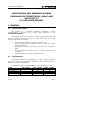
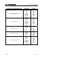
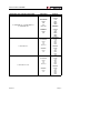
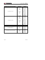
RM-404
MONITORING AND WARNING ALARMS PROGRAM FOR
TERRESTRIAL, CABLE AND SATELLITE TV.
(TV EXPLORER SERIES).
- 0 MI1980 -
USER’S MANUAL. RM-404.
T A B L E
O F
C O N T E N T S
GENERAL........................................................................................1
1.1 General description .....................................................................1
1.2 Specifications .............................................................................1
1.3 Requirements hardware and software ...........................................5
1.4 Installation ................................................................................5
1.4.1 Software Installation ..............................................................5
1.4.2 Legal conditions.....................................................................6
1.5 Connection between TV EXPLORER and the PC. ..............................7
2 INSTRUCTIONS TO USE THE RM-404 CONTROL SOFTWARE .....................8
2.1 Start .........................................................................................8
2.2 Menu Bar...................................................................................9
2.2.1 File ....................................................................................10
2.2.2 Model .................................................................................10
2.2.3 Report................................................................................11
2.2.4 Test Point ...........................................................................12
2.2.5 View ..................................................................................15
2.2.6 Configuration ......................................................................16
2.2.7 Language............................................................................20
2.2.8 Help ...................................................................................20
2.3 Steps for Monitoring - Toolbar ....................................................21
1
USER’S MANUAL. RM-404.
USER’S MANUAL. RM-404.
MONITORING AND WARNING ALARMS
PROGRAM FOR TERRESTRIAL, CABLE AND
SATELLITE TV
(TV EXPLORER SERIES).
1 GENERAL
1.1
General description
This program is a software application developed to allow
communicating a computer and a field meter belonging to the
TV EXPLORER SERIES
This program allows you to monitor in real time measures that the field
meter is obtaining and to store them in a PC. Next some of the most
important functions are detailed:
•
•
•
•
•
1.2
Analyse the performance of signals as time goes by.
Control signals through alarms in order to keep them within
optimal parameters.
Warnings by means of electronic mail about any message of
alarm.
Generate different reports with the content obtained from
monitoring.
Automatic report sending to the electronic mail.
Specifications
The program offers some possibilities in order to analyse different
types from signals and modulations available at the present time in TV
systems (Terrestrial and Satellite).
The frequency range varies depending on the equipment you have:
MODEL
TV EXPLORER
TV EXPLORER
TV EXPLORER
TV EXPLORER
06/2013
II
II+
HD
HD+
5 MHz — 860 MHz
YES
5 MHz — 1000 MHz
YES
YES
YES
950 MHz — 2150 MHz
YES
YES
YES
YES
Page 1
USER’S MANUAL. RM-404.
SYSTEMS THAT CAN BE MONITORED
TV EXPLORER II / TV EXPLORER II+
TV EXPLORER HD
TV EXPLORER HD+
Page 2
ANALOGUE
Pal BG
Pal DK
Pal I
Pal M
Secam L
Secam BG
Secam DK
NTSC M
FM
Satellite
Pal BG
Pal DK
Pal I
Pal M
Secam L
Secam BG
Secam DK
NTSC M
FM
Satellite
TV EXPLORER HD ATSC
Satellite
NTSC M
FM
Palm
TV EXPLORER HD ISDB-T
Satellite
FM
Pal M
NTSC M
TV EXPLORER HD DTMB
Pal BG
Pal DK
Pal I
Pal M
Secam L
Secam BG
Secam DK
NTSC M
FM
Satellite
DIGITAL
DAB
DVB-T
DVB-H
DVB-C
DVB-S
DVB-S2
DAB
DVB-T
DVB-T2
DVB-H
DVB-C
DVB-S
DVB-S2
J83
8VSB
DVB-C
DVB-S
DVB-S2
DSS
ISDB-T
DSS
J83
DVB-C
DVB-S
DVB-S2
DAB
DVB-C
DTMB
J83
DVB-S
DVB-S2
DSS
06/2013
USER’S MANUAL. RM-404.
MEASURES THAT CAN BE MONITORED
ANALOGUE
Terrestrial:
TV EXPLORER II / TV EXPLORER II+
TV EXPLORER HD
LEVEL
C/N
V/A
DESV FM
Satellite:
LEVEL
C/N
DIGITAL
Terrestrial:
POWER
C/N
MER
CBER
VBER
Satellite:
POWER
C/N
MER
CBER
VBER
LBER
Terrestrial:
Terrestrial:
TV EXPLORER HD+
LEVEL
C/N
V/A
DESV FM
Satellite:
LEVEL
C/N
Terrestrial:
TV EXPLORER HD ATSC
LEVEL
C/N
V/A
DESV FM
POWER
C/N
MER
CBER
VBER
Satellite:
POWER
C/N
MER
CBER
VBER
LBER
Terrestrial:
POWER
C/N
MER
SER
CBER
VBER
Satellite:
Satellite:
LEVEL
C/N
06/2013
POWER
C/N
MER
CBER
VBER
LBER
Page 3
USER’S MANUAL. RM-404.
MEASURES THAT CAN BE MONITORED
ANALOGUE
DIGITAL
Terrestrial:
Terrestrial:
LEVEL
C/N
V/A
DESV FM
POWER
C/N
MER
SER
CBER
VBER
Satellite:
Satellite:
LEVEL
C/N
POWER
C/N
MER
CBER
VBER
LBER
Terrestrial:
TV EXPLORER HD ISDB-T
Terrestrial:
TV EXPLORER HD DTMB
ALARM CONFIGURATION IN:
Page 4
LEVEL
C/N
V/A
DESV FM
POWER
C/N
MER
SER
CBER
VBER
Satellite:
Satellite:
LEVEL
C/N
POWER
C/N
MER
CBER
VBER
LBER
ANALOGUE
DIGITAL
TV EXPLORER II / TV EXPLORER II+
TV EXPLORER HD
LEVEL
C/N
V/A
TV EXPLORER HD ISDB-T/ATSC/DTMB
LEVEL
C/N
V/A
POWER
C/N
MER
CBER
VBER
LBER
POWER
C/N
MER
CBER
VBER
LBER
SER
06/2013
USER’S MANUAL. RM-404.
1.3
Requirements hardware and software
In order to use the program, your computer must fulfil the following
requirements:
1.4
•
Personal compatible computer Pentium or higher.
•
Compatible operating systems: Windows 98, Windows XP, Vista
Windows, and Windows 7.
•
Screen Resolution 1280 x 800 for a correct display.
•
23 MB of space available in the hard disk.
•
Puerto USB available.
Installation
1.4.1 Software Installation
The RM-404 install file is provided in a memory support (pen drive or
CD-ROM) or can be download from the page “Firmware and Software” at
the
"Download"
area
in
the
PROMAX
Web
page
(www.promaxelectronics.com).
Find the file (setup.exe) and start installation following these steps:
06/2013
1.
Double click on the file to run it.
2.
Follow the instructions
installation process.
3.
The install program creates, by defect, a folder in C:\ Program
files \ PROMAX \ RM404 where it copies the program files and
the folder “Database”, this is the folder where, by defect, a
set of folders are copy in order to store all data files. It also
creates a shortcut to the program in the desk and in “Start \
All Programs \ PROMAX \ RM404”.
4.
To run the program click twice on the icon of direct access
RM404 that is in the desk.
that
will
guide
you
during
the
Page 5
USER’S MANUAL. RM-404.
5.
In the section “Instructions to use” the program operation is
explained with detail.
1.4.2 Legal conditions
Read the contract carefully in its entirety before you install the
program. Installing the program means that you have accepted the following
terms and conditions.
1. SUBJECT. The subject matter of this Contract is the grant to the end
user by PROMAX ELECTRONICA, S. L. a non-exclusive and nontransferrable personal license to use this version of the program for an
indefinite period of time.
2. LICENCE. The Licence of Use granted hereby refers exclusively to the
end user, who shall be considered legitimised to use the program only.
3. OWNERSHIP OF THE SOFTWARE. The end user acknowledges that
the program referred to in this Contract is the exclusive property of
PROMAX ELECTRONICA, S. L. The end user may only acquire the
personal and non-transferrable right to use the software that is the
subject matter of this Contract for the purposes herein expressed.
Since the program granted is protected by industrial and intellectual
copyright, infringements by the user of these aforementioned
obligations will give rise to the corresponding liabilities in accordance
with the legislation in force.
4. RESOLUTION. The licence or authorisation of use is granted for an
indefinite period of time. However, in the event of non-compliance by
the end user with any of the clauses hereof, the Contract may as of
right be terminated without any legal formality.
5. EXPLANATORY PROVISION. Not with standing the accuracy of the
software granted, PROMAX ELECTRONICA, S. L. is fully exempt of
liability for consequences arising from any possible omission existing in
the program or from improper use by the end user of any of the
information it contains and generates. Nor can PROMAX
ELECTRONICA, S. L. be held liable for the suitability or accuracy of
the data obtained for particular purposes or functions, since the only
obligation of the latter, under this Contract, is the provision of means
and not of results.
6. FINAL CLAUSE. The use of this software referred to herein signifies
the tacit and unconditional acceptance of its conditions.
Page 6
06/2013
USER’S MANUAL. RM-404.
7. JURISDICTION. Both parties, explicitly waiving any rights that may
correspond to them, agree to submit all controversies that may arise
from this Contract to the jurisdiction and competence of the Judges ad
Courts of Barcelona.
1.5
Connection between TV EXPLORER and the PC.
The TV EXPLORER and the PC is connected by means of the USB cable
data transmission that is provided with the equipment.
Connect an end to a free USB port at the PC. Connect the other end to
the mini-USB port located at the back of the meter.
Figure 1.- Connection between TV EXPLORER and PC.
If the communication between the program and the meter does not
work, maybe is because the USB driver for the communication of PROMAX
devices has not been installed. This driver can be downloaded from the page
“Firmware and Software” at the download area in the PROMAX web page
(http://www.promaxelectronics.com/).
06/2013
Page 7
USER’S MANUAL. RM-404.
2
INSTRUCTIONS TO USE THE RM-404 CONTROL
SOFTWARE
Start
2.1
Follow the next steps to start using the RM-404 program:
1.
Check the TV EXPLORER is ON.
2.
Check the connection cable
computer is well connected.
3.
Double click on the icon RM-404 at the desk to run the program.
4.
It appears the main window of the program (see figure below).
between
TV
EXPLORER
and
Figure 2.- RM-404 Main Window.
The main window has a menu bar at the top. Below this, there is a
toolbar with some icons, which are enumerated according to the steps to
follow in a monitoring process. Occupying the most of the main window
there is a grey area where the tables with monitoring data are shown.
5.
Page 8
Follow the steps by order to start the monitoring process (see
section "Steps for monitoring").
06/2013
USER’S MANUAL. RM-404.
LEGAL NOTE
In any case PROMAX ELECTRONICA, S. L. responsible for data loss or
other damages that may cause this program directly or indirectly. Although
we put our efforts in developing a useful and reliable product, it is
understood that the use of the program and data and information generated
with it are the sole responsibility of the user.
2.2
Menu Bar
Options on the menu bar are:
File:
It contains options to manage and quit the program.
Model:
It allows you to select the transmission standard: DVB,
ATSC, ISDB-T or DTMB.
Report:
It allows you to open or create a report table.
Test Point:
It contains the options to create or edit test points in
order to be monitored.
View:
It contains the options to view the tables.
Config.:
It contains several options to configure.
Language:
It allows you to select the program language between
English and Spanish.
Help:
It contains the options to access the user’s manual and
the license option.
Next sections explain each one of these menus.
06/2013
Page 9
USER’S MANUAL. RM-404.
2.2.1 File
Options on the File menu are:
-
Open report.
-
Report Viewer.
-
Save Test Point Set.
-
Exit.
The option Open Report opens a window from where it is possible to
recover a report previously created (QRP format), to view data generating a
report “per time” and to print it.
The option Report Viewer generates a report from data taken from
the opened Table Report. The type of view can be:
-
Min / Max / Avg:
This report shows the average, minimum and
maximum value of all acquisitions made.
-
By Time:
This report shows all measures based on time.
-
By Test Point:
This report shows all measures grouped by
test point.
-
By Alarm:
This report shows all measures out of limit.
The option Save Test Point Set allows you to save the table with the
test points in a file with extension “*.db” and the name that the user
assigns to it. When the test point table is modified, there is necessary to use
this option to save changes made.
The option Exit closes the program (without confirmation).
2.2.2 Model
It allows you to select between the three worldwide standards for
digital television transmission:
-
DVB.
-
ATSC.
-
ISDB-T.
-
DTMB.
Page 10
06/2013
USER’S MANUAL. RM-404.
If the meter is connected to the computer and communication with the
program is done, the program will automatically detect the standard
transmission to which the meter belongs. On the contrary the user should
select it manually.
2.2.3 Report
Options on the Report menu are:
-
New Table Report.
-
Open Table Report.
-
Export to .csv
A Report Table is a new table that gathers the data that the meter will
take during the monitoring process. Afterwards, the report will be based on
the report table with these meter data.
The option New Table Report allows you to create an empty report
table. When clicking on this option a window pops-up in order to assign a
name and to save a new file as a report table. By defect it is opened in the
folder “Measurements” of the program. This table will contain all the
measures being captured since the moment that begins the monitoring
process. Data will be recorded in an automatic way. When stopping the
monitoring process it will not store any data anymore.
Figure 3.- Report Table Example.
The option Open Table Report allows the user to open a table of an
already existing report. When clicking on this option a window pops-up in
order to select a file of a report table that the user wants to open. By defect
this window opens in the folder “Measurements”. This table will appear in
the viewing window of the program. With this table a report “per time” will
be able to be generated.
06/2013
Page 11
USER’S MANUAL. RM-404.
The option Export to. csv exports data from the Table Report to a file
with csv extension. The CSV format is an open format to represent data in
tabular form, where the columns are separated by a semicolon and the rows
by a new line. This type of file can be opened with a standard spreadsheet
program .
2.2.4 Test Point
Options on the Test Point menu are:
-
Open Test Point Set.
-
New Test Point Set.
-
Edit Test Point.
-
Edit Test Point Table.
The Test Points are the points defined by the user so the program
measures and monitors them through the meter.
The option Open Test Point Set allows the user to open a table of test
points already existing. When clicking on this option open a window to select
the table file with the test points. By defect it is opened in the folder
“TestPoints” of the program.
Figure 4.- Example of Table of Test Points.
Page 12
06/2013
USER’S MANUAL. RM-404.
The option New Test Point Set creates a table of Test Points. This
table appears in the program main window. This table has to be filled up
with test points (channels or frequencies) to be monitored by the user. This
table is filled up through the options available in the program and explained
next. Once defined the table it must be saved. The user can make many
tables of test points as he wants in order to select later the one that needs.
The option Edit Test Points opens a window that allows the user to
change the parameters of the point on the selected table. For it the user
should follow these steps:
1.- When selecting the option Edit Test Point a window pop-ups to
edit a Point of Test.
Figure 5.-
NOTE: In the case of ISDB-T standard, it also allows selecting
layer.
2.- Next the user should select a Test Point from the Test Point Table
and press the Edit button.
3.- The window pick up the data of the Test Point selected.
Figure 6.-
06/2013
Page 13
USER’S MANUAL. RM-404.
4.- Now the user, by clicking on the field and typing a new value or
by selecting it from the dropdown menu, can change the data
field.
5.- Once the user has finished the field edition, he has to click on the
Insert button. If everything is correct, the new values will replace
the previous ones. If any field is unfilled or the new value exceeds
the maximum value or it does not reach a certain minimum value,
the user receives an error message.
The Edit Test Points option opens a window with several options to
edit the Test Point table.
Figure 7.-
Following, each option is explained in detail:
The option Add TER access to a database with the more common
terrestrial plan channels of several countries. The user should select one of
these plan channels. Each plan channel is composed by a list of test points
that can be selected and added to the table of test points created by the
user. The user can also select standard transmission between analogue and
digital.
The option Add SAT access to a database with the more common
satellite plan channels. The user should select one of these plan channels.
Each plan channel is composed by a list of test points that can be selected
and added to the table of test points created by the user.
The list with all transponders of the different satellites is updated. In
the case that the parameters of the transponders change, the user should
identify them with the meter (Auto ID key) and to visualize the new
parameters, by unfolding the menu that contains the plan channels on the
meter (Key D and A). Next the user will be able to modify them in the list
that has been created.
Page 14
06/2013
USER’S MANUAL. RM-404.
The Copy option copies the line selected in the user's test point table in
the clipboard memory.
The Cut option cuts the line selected in the user's test point table and
saves it in the clipboard memory.
The Paste option inserts in the user's test point table the test point line
saved in the clipboard memory. The same line can be pasted several times.
The option Add New adds an empty new line at the end of the user’s
table.
The option Insert New adds an empty new line upon the selected line
of the user’s table.
The option Delete deletes the line selected in the table of the user’s
table.
The option Delete All deletes all the lines of the user’s table.
2.2.5 View
Options on the View menu are:
-
Test Point Table.
-
Report Table.
-
Add Test Points From Exploration.
The option Test Point Table puts in first plane of the main window the
Test Point Table.
The option Report Table puts in first plane of the main window the
Report Table.
The option Add Test Points From Exploration allows the user to
recover test points used in the user’s TV EXPLORER meter, by adapting
them to a new list of Test Points that work with the monitoring program. To
use this option, previously the user must establish communication between
the program and the meter through the option "Search COM PORT".
06/2013
Page 15
USER’S MANUAL. RM-404.
To do this, first the user has to select band: TER (terrestrial) or SAT
(satellite). Next he has to click on the button “Receive Exploration” to
download the whole list from the meter. After downloading the user should
unfold the “Channels List” and select one. Then click on “Add Channels”.
The selected channels will be added to the list of Test Points. In the case of
selecting satellite band the user should select suitable values for Low
Oscillator and High Oscillator.
IMPORTANT
The option Add Test Points From Exploration only works with channels
plans created by the meter by means of the “Explorer” function.
2.2.6 Configuration
Options on the Configuration menu are:
-
Operating
-
Mail
-
Data Report
-
Monitor Energy Saver
-
Alarms
-
GPS
-
Shutdown
The option Operating, allows the user to select between four forms of
work: Continuous, Loops, ON/OFF, Cycles or Loop Single Test Point.
The Continuous mode works in uninterrupted monitoring until the
user stops it by pressing the STOP icon on the toolbar.
The Loops mode makes the same measurements over a number of
times defined by the user. When it reaches this number it stops monitoring
automatically.
The ON/OFF Cycles makes measurements according to cycles of work
that are defined by the user. The user must enter working time (monitoring
time) in the field “Time ON” and the stopping time (not monitoring) in
“Time OFF”. A work phase is followed by a stop phase. When finishing the
stop phase it begins the work phase again. It will be looping until the user
click on the STOP button in the Operation window to stop the process.
Page 16
06/2013
USER’S MANUAL. RM-404.
The Autoconfiguration alarm option enables the automatic alarms
that are defined in the menu Alarms/Auto in the Operating menu.
The Loop Single Test Point mode monitors the first test point of the
table. The meter will be set during the first cycle and then it will take
continuously measures.
The Extra delay time for measurement defines an additional waiting
time to measure, once the equipment has been configured with the
information of the test point (up to 60 seconds).
The Time between test points defines a stop time when monitoring
between each test point in the table (up to 43200 seconds).
The Time between loops defines a stop time when monitoring
between each test point table (up to 86400 seconds).
The Sending reports option allows sending periodic reports every
time interval defined by the user (up to 2880 minutes). The user can also
select the type of report or reports to be received (section 2.2.1).
When capturing over 200.000 records in continuous mode, the user
must modify a parameter within BDE ADMIN.
In order to change this parameter the user has to go to the Windows
Control Panel and double click on the icon “BDE Administrator” icon, then
select
the
tab
“Configuration”
and
open
the
folders
“Drivers/Native/Paradox”. In the window that appears there are some
parameters, and the user should change the parameter BLOCK SIZE (by
default to 2048) to the desired value. The maximum record number is
2 billions (2x10¹²).
The option Mail contains two options: E-Mail and Test mailing. In the
E-Mail option the user defines the email address at which he wants to
receive the program information, as alarms or reports. The user can define
up to three different email addresses, a main one and two secondary. He
can enable or disable the sending to the secondary emails. It is advisable
not to use the e-mail manager program of the user. Otherwise Outlook
Express is recommended.
The Test Mailing performs a test mailing with the email addresses
defined by the user in order to check that they have been configured
correctly. In case of using the e-mail manager program of the user, to work
without problems the user has to disable the notification for emails sent by
other applications from the email manager (see figure).
06/2013
Page 17
USER’S MANUAL. RM-404.
Figure 8.-
The option Data Report allows the user to define a series of data that
will appear in the report, such as the company data, report data, technical
data and meter data.
The option Alarm allows the user to define several types of alarms
based on the value of several parameters, such as CBER, VBER, LBER, etc…
There are two ways to set alarms. In Manual mode or in Automatic mode.
In Manual mode to set an alarm first the user should select a test
point and then edit the values. When the box “Alarm” is ON it enables all
the alarms of the selected test point, when is OFF it disables all them. When
the box "Mailing" is checked it sends an email when the alarm goes off. It
also appears an icon on the toolbar that indicates that this option is checked.
If this box is unchecked it will not send any email but it will be stated in the
report that the alarm went off.
Page 18
06/2013
USER’S MANUAL. RM-404.
Figure 9.-
In Automatic mode user can define a tolerance for each type of
measurement (level, C/N, V/A, MER) and the alarm is automatically applied
to all test points of the table when the measurement is above or below the
tolerance. The alarm for the type of measure must be ticked in the
Activated column. For the automatic alarm system works, it must be ticked
the Autoconfiguration alarm option in the Configuration/Operating
menu. If not it will work in the manual mode.
Figure 10.-
The option GPS allows the user to connect a GPS device to the
computer to use it as a geo-locator in the measures taken through the
meter. The user defines the communication port and the baud rate for the
serial port to comunicate with the GPS. Checking the box "Enable the GPS
reception" it activates the communication with the GPS. To start the GPS
signal searching process you should click on the button "Search signal". To
stop the process you should click on the button "Cancel".
06/2013
Page 19
USER’S MANUAL. RM-404.
The Shutdown option allows the user to define the date and hour to
turn off the computer. When the shutdown function of your PC is activated it
appears the icon of a clock on the toolbar. The program will automatically
save the data captured before turning off. The user can also select the type
of report and the date and hour to send. Reports are saved by default in the
folder:
“C:\Program\Files\PROMAX\RM404\Database\SaveReports\”.
2.2.7 Language
It allows selecting between languages Spanish or English.
2.2.8 Help
Options on the Help menu are:
-
Tutorial.
-
About.
-
Buy RM-404.
-
Insert license.
The option Tutorial give you access to the user’s manual in pdf format.
The option About sample shows the version number of the software.
The RM-404 program has a trial period of 30 days, after which it does not
work unless the license is activated.
The option Buy RM-404 gives access to a code that has to be provided
when purchasing the program in exchange for the activation code of the
program.
The option Insert license gives access to a window where you must
enter the code supplied when purchasing the program. The user should copy
the activation code in case of future re-installations.
VERY IMPORTANT NOTE
The purchased license is for an unlimited period, but restricted to the PC
from which the user purchased the code.
Page 20
06/2013
USER’S MANUAL. RM-404.
2.3
Steps for Monitoring - Toolbar
The toolbar consists of several icons arranged according to the steps
for monitoring. They are:
Figure 11.-
The first step in monitoring is to create or display a table to store
measurement data. To create a new table, the user must click on “New
Table Report”. In the case that the table had been created previously he
must click on “Open Table Report”.
Figure 12.-
The second step in monitoring is to create or display a table with
measurement points or test points to be monitored. In order to create a new
table, the user must click on “New Test Point Set”. In the case that the
table had been created previously he must click on “Open Test Point Set”.
After finishing click on “Save Test Point Set”.
Before proceeding to the next step, if the user wants the program to
notify in case of problems with a signal, the user should set the alarms for a
test point.
In order to set the alarm of a test point, first the user should select the
test point he wants to control. Then select the option Alarms on the
Configuration menu. Next put to ON the “Active” tab and edit the limit
values for each measure.
For Level, C/N, MER and V/A the user should select the minimum value
and the maximum value. To disable an alarm put both values to 0.
For CBER, VBER and LBER the user should select the minimum value
and the maximum value. To disable an alarm select the option OFF.
Repeat the process with each test point you want (ON = Enabled /
OFF = Disabled).
06/2013
Page 21
USER’S MANUAL. RM-404.
Figure 13.-
The third step in monitoring is to establish communication with the
meter. Previously, the user must verify that the computer is connected to
the meter by means of the USB cable provided. Next click on “Search COM
Port” and the program will change to status “DETECTING” until it finds the
port of communication with the meter. The program gives a confirmation
message and the status will change back to “STOP”.
Figure 14.-
The fourth step is start monitoring. Clicking on icon PLAY
the
monitoring process will begin. The program will automatically store the
measures collected from the test points to the table report.
Page 22
06/2013
USER’S MANUAL. RM-404.
To stop the monitoring at any time the user must click on the icon
STOP
. The monitoring will not stop until the measurement at that
moment is finished.
Figure 15.-
The fifth step is the visualization of the data collected during
monitoring. The program is able to generate a report according to the data
the user want to see:
-
Min/Max/Avg
The report presents the average, minimum
and maximum value of all acquisitions.
-
By Time:
The report will present all measures based on
time.
-
By Test Point:
The report presents measures grouped for
each test point.
-
By Alarm:
This report shows all measures out of limit.
In addition to follow the five steps just described, the user has
additional information on the right part of the toolbar, where there is a
window with the information of the status and the system hour.
Figure 16.-
The messages of the state information can be:
-
STOPPED:
When the monitoring process is stopped.
-
MONITORING:
When the monitoring process is working.
-
SEARCHING COM: When searching for the COM port where the
meter is connected.
-
WAITING:
06/2013
When working in Cycle mode and it is in the
OFF phase.
Page 23
USER’S MANUAL. RM-404.
Page 24
06/2013