1
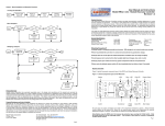
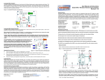
 RRC3 – Rocket Recovery Controller 3 LCDT (LCD Terminal) User Manual Revision 1.02 Missile Works Corporation
PO Box 1725, Lyons CO 80540
www.missileworks.com
1
LCD Interface The LCD interface can be used to configure, review flight data on, and perform diagnostics on your altimeter. It’s a handy way to interact with the altimeter at the field. Connecting the LCD Before connecting the LCD module, be sure that the altimeter is powered off, and that the USB dongle is not connected. The LCD module connects to the altimeter via the ribbon cable included with the LCD. The connectors on the ends of the cable are identical, and either can be connected to either device. The orientation of the cable is determined by the red stripe down one side. On the altimeter, the plug is connected with the red stripe adjacent to the piezo buzzer. On the LCD unit, the plug is connected with the red strip to the right, when the LCD is oriented such that the text between the button pairs is right side up. The connectors are keyed, to prevent the cable from being plugged in backwards. After connecting the LCD, apply power to the altimeter, at which point you should hear three quick beeps from the piezo, and the startup screen displays on the LCD. The startup screen appears similar to the following After a few seconds, the startup screen clears, and the Home Menu is displayed. If the display is difficult to read, you can adjust the contrast by turning the knob to the right of the cable connector on the LCD unit. Please note that the LCD is not backlit, so it will be difficult, if not impossible, to read in poor lighting. 2
Navigating the LCD Menus The LCD navigation is based around the four buttons on each side of the display. The center of the display shows the subject, and by each button is an icon or word, describing the button’s action. In the Home Menu, the top left button is used to View settings, the bottom left button shows Flight Log data, the top right button brings up the Diagnostics menu, and the bottom right button brings up the Settings menu. Some menus use arrows to indicate navigation. As an example, in the View Settings menu, the following may appear In this case, the top left button will take you up one level in the menus, while the bottom left button will take you to the next setting. The buttons on the right are not used on this menu page. Viewing Altimeter Settings The current altimeter configuration for flight critical settings can be reviewed by accessing the View menu (top left button) from the Home Menu. Note that the AUX settings cannot be viewed from this menu. Settings are displayed two items per page, starting with the Arm and Main altitudes. Please note that some values are displayed as a fraction of their actual value. As an example, the actual arm altitude is the value displayed times 10, and the main altitude is the value displayed times 100. In this example, the RRC3 will arm once it reaches 300 feet above the pad, and the main will deploy when the rocket has descended back down to 500 feet above the pad. 3
The second page is reached by pressing the next page (bottom left) button, which displays the Deployment Mode and Low Voltage Lockout level. Deployment Modes are defined as follows: 1. Dual Deploy Primary 2. Dual Deploy Backup 3. Apogee Only Drogue @ Apogee / Main @ Main Deployment Altitude Drogue @ Apogee + Drogue Delay / Main @ Deployment Altitude Drogue @ Apogee / Main @ Apogee + 1 sec The Low Voltage Lockout validates that the RRC3 battery voltage is above a minimum voltage level that’s appropriate for your battery system. A setting of (2) disables this lockout feature. If this lockout feature is enabled, and the battery voltage is at or below the specified setting, the unit will not arm itself for flight, and instead activate the POST fault code report mode (see the POST fault codes) Reviewing Flight Data Pressing the Log (lower left) button from the Home Menu allows you to review data from the Flight Log (ie. the last flight recorded. Items are displayed two per page, as shown below: There are a total of 8 pages of data displayed, with the first 5 providing data for the latest flight, and the last 3 providing cumulative statistics for the altimeter. The items displayed, in order of display, are: MaxAlt Apogee for the latest flight MaxVEL Maximum velocity for the latest flight Pad Number of seconds between power on and liftoff Apogee Number of seconds between liftoff and apogee Chute Number of seconds between apogee and the rocket reaching the ground Power On Altimeter bay temperature at power on Launch Altimeter bay temperature at liftoff Low Lowest altimeter bay temperature during last flight Drogue Average Velocity during drogue descent Main Average Velocity during main descent Flights Total number of flights on the RRC3 Time Total flight time on the RRC3 Altitude Total vertical distance up the RRC3 has travelled 4
Note that each item has associated “units” as established by the Audio / LCD / Telemetry Units setting. Some items also have a superscripted “icon” to assist in interpretation: Hourglass Degrees Sigma All “Time” related items All “Temperature” related items All “Total” related items Running Diagnostics The altimeter Diagnostics Menu can be accessed the Diag menu (top right button) from the Home Menu. The Diagnostics Menu is split into three settings: Inputs (bottom left button), Outputs (top right button) and Pressure/Temperature/Voltage (bottom right button). Press the button for the diagnostics you wish to use. Input Diagnostics Selecting Input Diagnostics displays the state of four key inputs ‐‐ the Drogue, Main and Auxilliary continuity status, and the state of the programming pushbutton. In the example above, there is continuity only on the Main terminals, and the pushbutton is not pressed. If a problem is identified, correct the issue and press the refresh (bottom left) button. Refresh causes the altimeter to scan the inputs, and update the display. If the state begins as shown above, then the programming pushbutton is held down while the refresh button is pressed, the display updates to match the following image. 5
Likewise, connecting a match (or test light) to the Drogue terminals and pressing refresh (while no longer holding the programming push button) results in the following display Output Diagnostics The Output Diagnostics allow you to verify the firing circuitry on your RRC3, as well as verify that the matches you’ve chosen can be fired by the RRC3’s firing circuitry. If your goal is to simply test the altimeter’s output circuitry, a single miniature Christmas tree bulb works well ‐‐ it provides sufficient resistance for the continuity circuitry to detect it as a charge, and will light up when the altimeter fires the output. WARNING: Testing the outputs with pyrotechnic materials connected to the outputs will result in their ignition. USE EXTREME CARE WHEN TESTING OUTPUTS WITH ANYTHING OTHER THAN LIGHT BULBS CONNECTED TO THE OUTPUTS. Once you have entered the Output Diagnostics Menu, the LCD will allow you to select which output is to be tested. Press the button associated with the output you wish to test: drogue (bottom left), main (top right), or auxiliary (bottom right). The altimeter will then produce a series of rapid warning beeps and display the confirmation screen. Pressing the top left button will return to the Output Diagnostics menu. Pressing the bottom left button will fire the selected output, and then return to the Output Diagnostics Menu. Pressure/Temperature/Voltage The Pressure/Temperature/Voltage Diagnostics allows you to monitor the ambient condition of the altimeter, but more importantly, to get a reading of your battery’s voltage under load. 6
Configuring the Altimeter The Settings Menu is reached by pressing the set (bottom right) button from the Home Menu. Within the Settings Menu are three sub‐menus for three groups of functions: Base (top right button) providing access to the most commonly used functions, Auxiliary (bottom right button) which provides control over the Auxiliary output, and Telemetry (bottom left button) which controls the data stream fed via the on‐board com port. All settings are modified via the same mechanism ‐‐ the altimeter displays the specific setting, as well as its current value. To change the setting value, use the buttons on the right to increase or decrease the setting, as shown in this example Here, the top left button maintains its function of taking you back one level, and the bottom left button navigates to the next setting. The top right button increases the setting value, in this case the Arm Altitude, until the maximum allowed value is reached, and the bottom right button decreases the value until the minimum allowed value is reached. Another setting mode used for some Auxiliary configuration options uses a +1/x10 method. This is used for settings where large values are possible, to minimize the number of button presses required. Pressing the top‐right button will increment the displayed value by 1. Pressing the bottom‐right button will multiply the displayed value by 10. In this case, 35 becomes 350. If the value multiplied by 10 exceeds the permissible range, the value will revert to zero. So, starting with the display above, pressing the bottom‐right button once will change the value to 350. Pressing it again will change it to zero. Base Settings The meanings of the Base Settings are defined in the Base Settings section of the RRC3 User Manual. The settings are presented in the following order LCD Value ARM ALT MAIN ALT DEPLOY MODE Setting Name Arming Altitude Main Deployment Altitude Deployment Mode 7
AUDIO SETUP UNITS SETUP LV LOCK PIEZO TONE DROG DELAY Audio Options Audio / LCD / Telemetry Units Low Voltage Lockout Level Piezo Tone Drogue Delay Auxiliary Settings The meanings of the Auxiliary Settings are defined in the Aux Output Control Settings section of the RRC3 User Manual. The settings are presented in the following order LCD Value AUX OCS AUX TRIGGER AUX OUTPUT AUX TIMER AUX COMPARE AUX CV Setting Name Aux Output Control Sequence (OCS) Aux Trigger Event Aux Output Control Value Aux Timer Interval Aux Comparator Operation Aux Comparator Value Telemetry Settings The Telemetry Settings are defined in the Flight Telemetry and Settings section of the RRC3 User Manual. The settings are presented in the following order LCD Value TELEMETRY OPS TELEMETRY DAT Setting Name Data Control Data Items Product Warranty Missile Works Corporation has exercised reasonable care in the design and manufacture of this product and warrants the original purchaser that the RRC3 is free of defects and that it will operate at a satisfactory level of performance for a period of one year from the original date of purchase. If the system fails to operate as specified, then return the unit (or units) within the warranty period for repair or replacement (at our discretion). The system must be returned by the original purchaser, and be free of modification or any other physical damage which renders the system inoperable. Upon repair of replacement of the unit, Missile Works Corporation will return the unit postage‐paid to the original purchaser. Product Disclaimer and Limit of Liability Because the use and application of this equipment are beyond our control, the purchaser or user agrees to hold harmless Missile Works Corporation and their agents from any and all claims, demands, actions, debts, liabilities, judgments, costs, and attorney fees arising out of, claimed on account of, or in any manner predicated upon loss or damage to property of, or injuries to or the death of any and all persons arising out of the use this equipment. Due to the nature of electronic devices, and the application and environments for those devices, the possibility of failure can never be totally ruled out. It is the responsibility of the purchaser or user of this equipment to properly test and simulate the actual conditions under which the device is intended to be used to ensure the highest degree of reliability and success. 8