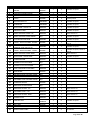
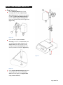
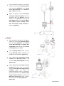
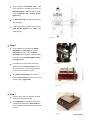
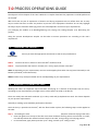
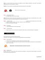
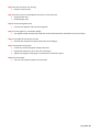
1
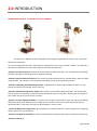
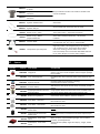
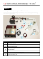
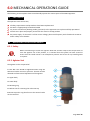
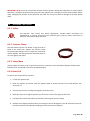
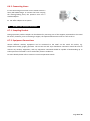
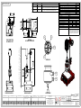
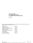
USER’S MANUAL OPERATION AND MAINTENANCE GUIDE TABLE OF CONTENTS 1.0 2.0 3.0 4.0 5.0 6.0 7.0 8.0 9.0 10.0 Preface Introduction Product Summary General Safety Instructions Unpacking & Assembling the GFD® Mechanical Operations Guide Process Operations Guide Maintenance Operations PSL Quality Certificates ANNEX 1 2 3 4 7 11 15 24 28 32 34 Other languages of this documentation can be found at: www.sigma-aldrich.com/glass-filter-dryers Page 1 of 36 1.0 PREFACE Dear CUSTOMER WELCOME TO THE GFD® A simpler approach to lab scale filtration and drying! The GFD® is an innovative laboratory solution filling a need in today’s R&D labs, whether in the chemical or pharmaceutical industry. Indeed, this replacement technology combines within one piece of equipment, existing filtration and drying methods and therefore actually supersedes Buchner filtrations and Tray drying. Established since 1989 in the pharmaceutical industry as a pioneer in containment and filtration technologies (production scale) PSL have used our world class experience to offer a better approach to Lab scale filtration and drying to the world of chemistry » The GFD®. This equipment is available in 3 sizes thus suiting the needs of small labs to kilo-labs, a product line designed to give the opportunity to perform the best scale-up studies in the global market today. Combining filtration and drying within one piece of equipment is the guarantee that liquid and solid separation process development benefit from: »Minimum Process Disruption »Batch Homogeneity »Improved Yield »Reduced Product Exposure »Process visibility Contrary to other larger sizes ANFD’s the GFD® has a unique feature, the Removable Filter Basket. This patent pending feature is an innovation in the industry and offers unique product handling experience. It guarantees: »Full Product Recovery »Easy Cleaning »Improved Yield Today, the GFD® is a laboratory process equipment meeting all the requirements of the global industry. Most of the liquid/solid separation requirements can be applied in this new apparatus which makes the GFD® a truly global solution that fits in every lab. We hope you will greatly benefit from your purchase and whish you to enjoy the GFD® Experience. Page 2 of 36 2.0 INTRODUCTION BEFORE USING THE GFD®, PLEASE READ THE FULL MANUAL. The GFD® User’s Manual has been designed to provide general guideline to safely set-up, handle and operate the equipment. As a process equipment the user’s requirements will determine how to use the GFD®, however, you will find in this manual information on what cannot be done and what could be done. “Section 3: Product Summary” displays all the technical core data of the GFD® such as specifications including all spares and options and the general arrangement drawing. “Section 4: General Safety Instructions” lists all the principal safety aspects to consider before, while and after using the GFD®. This section is to be read before handling, setting-up and operating the GFD®. “Section 5: Unpacking and Assembling the GFD®” explains how to unpack and assemble the GFD® in a safe manner and how to set the GFD® prior to first use. “Section 6: Mechanical Operations Guide” deals with the set-up and handling of the GFD®. You will discover how to use main components and perform basic mechanical actions on the GFD®. We also give an example of how a GFD® can be set-up in line with a reactor. “Section 7: Process Operations Guide” is a guide to use the GFD® with products. Each user will dry and filtrate different products with different process requirements and this section can only describe certain ways to operate the GFD® in a process that may not be applicable in certain cases. “Section 8: Maintenance Operations” gives guideline to maintain the GFD® in order to guarantee its longevity and the quality of its performances. “Section 9: PSL Quality Certificates” contains the Declaration of Engineering and the certificate of conformity. “Section 10: Annex 1” Page 3 of 36 3.0 PRODUCT SUMMARY 3.1 Product Code PRODUCT CODE VOLTAGE PF-00001-230 230v - 50 HZ PF-00001-115 115V - 60HZ 3.2 PLUG CONNECTION UK: Type G, BS 1363 – (13A/230-240V 50Hz grounded and fused). Europe: Type E/F Hybrid CEE 7/7 (16A/250V grounded). US: NEMA 5-15 (15A/125V grounded). Japan: JIS C 8303, Class I (15A/100V grounded) General Design Data Filtration area 0.002M² Cake volume 0.1 Litre Cake depth (max) 50mm Volume 0.3Litres Vessel Jacket Unit Design temperature (Min) - 25 (-13) - 25 (-13) ºC (ºF) Design temperature (Max) 150 (302) 150 (302) ºC (ºF) Design Pressure (Min) FV FV barg (psig) Design temperature (Max) Area Classification Internal/External 0.5 (7.25) 0.5 (7.25) barg (psig) The PSL GFD® is not classified as containment equipment and therefore has to be used in conjunction with other equipment suitable to protect operator from exposure to potent compounds. OEL 3.3 Safe Area Mechanical Data Product contact materials Product contact areas will be Borosilicate 3.3 Glass, PTFE coated stainless steel, polypropylene, Silicone, Viton unless otherwise stated. Non Product contact materials 304L Stainless steel, Powder coated mild steel. Some minor proprietary procured items such as pipe clips may only be available in lower stainless steel grades. Some proprietary procured items, will be provided in the manufacturers' standard materials. Vessel/basket clamping 304L Stainless steel quick release clamp. PTFE lined. Filter basket Polypropylene filtration basket. Filter cloth is welded to the base of the basket. Filtration media Polypropylene cloth, nominal pore size 20μm. Basket o-rings 3mm section Silicone White - 60 shore hardness. Filter basket support Polypropylene plate with filtration holes. Page 4 of 36 Heating Jacket The base jacket is constructed in Borosilicate 3.3 Glass. KF15 Flange connections for inlet and return of heating/cooling fluid. Vessel Support 304L stainless steel, Powder coated mild steel. Agitator PTFE blade with 16mm diameter PTFE coated stainless steel shaft. Agitator seal PTFE seal rated FV and 0.5 barg (7.25 psig). Agitator Positioning Manual rack and pinion agitator/drive raise/lower system in anodised aluminium with glass fibre reinforced polyamide handwheel and clamping knob. Speed of rotation 5-100RPM. Vessel process stoppers Rodaviss Polyurethane cap, Borosilicate 3.3 Glass stopper, Viton o-ring seal. 3.4 Electrical Data Motor Motor Controls RPM Plug Connection 3.5 44W motor, 115 V 60 Hz / 240 V 50 Hz IP55 rated. Output torque 406Ncm. On/Off, Clockwise (Plough), Anti-clockwise (Smooth), Speed adjustment. Digital LCD Display, 3 digits, 1 rpm accuracy. UK: Type G, BS 1363 – (13A/230-240V 50Hz grounded and fused). Europe: Type E/F Hybrid CEE 7/7 (16A/250V grounded). USA: NEMA 5-15 (15A/125V grounded). Japan: JIS C 8303, Class I (15A/100V grounded). General Arrangement Drawing Please see Annex 1 3.6 Options PICTURE N/A PART No PART NAME ID00001 cGMP certification IP00111 Heat Transfer Jacket Connector Straight IP00045 Heat Transfer Jacket Connector 90deg Elbow IM00112 Polypropylene Basket, Nominal Pore size: 7 micron IM00113 Polypropylene Basket, Nominal Pore size: 12 micron IM00115 Stainless Steel basket, Nominal Pore size 5 micron IM00116 Stainless Steel basket, Nominal Pore size: 10 micron IM00117 Stainless Steel basket, Nominal Pore size: 20 micron DESCRIPTION Documents certifying compliance to FDA regulation 21CFR. Copy of GFD® test document. Certificates of materials of construction. DN 15 Chrome plated steel with FEP o-ring seal, thread M16 x 1mm Pitch. Polypropylene filtration basket. Filter cloth is welded to the base of the basket. 316L filtration basket. Filter media is welded to the base of the basket. Page 5 of 36 IM00119 Alloy 22 basket, Nominal Pore size 5 micron IM00120 Alloy 22 basket, Nominal Pore size: 10 micron IM00121 Alloy 22 basket, Nominal Pore size: 20 micron IM00122 Agitator Stainless Steel IM00123 Agitator Alloy 22 316L Stainless steel blade with 16mm DIA 316L Stainless Steel Shaft. Alloy 22 blade with 16mm dia Alloy 22 Shaft. IP00124 Basket O-ring – Viton 3mm section Viton – 70/75 Shore hardness. IP00125 Basket O-ring – White perfluoroelastomer 3mm section Perfluoroelastomer – 70/75 Shore hardness. Vacuum Bottle 10 Litre White Polypropylene bottle and 2 way connectorTPE seal -10...+135 °C, autoclavable. Temperature Infra-red probe Digital Pyrometer, LCD 4 Digit display, 3 Hz sampling rate, resolution 0.1°C, temp range 30°C to 200°C, Aluminium housing, stainless steel sensor head. Instrument IP20, sensor head IP65. INCLUDED: Rodaviss to GL nozzle adaptor and mains power adaptor. IM00154 IP00056 3.7 Alloy 22 filtration basket. Filter media is welded to the base of the basket. Spares PICTURE PART No PART NAME MG00008 Stopper Kit IM00083 PTFE coated Agitator DESCRIPTION Rodaviss Polyurethane cap, Borosilicate 3.3 Glass stopper, Viton o-ring seal. Include complete rodaviss stopper package for lid nozzles. PTFE blade with 16mm diameter PTFE coated stainless steel shaft. MG00006 Agitator Seal Kit PTFE seal rated FV and 0.5 barg (7.25 psig). Complete with rodaviss connector. IM00071 Pressure Clamp 304L Stainless steel quick release clamp. PTFE lined, powder coated. IM00084 Polypropylene Basket Nominal Pore Size 20μm Polypropylene filtration basket. Filter cloth is welded to the base of the basket. Media: 20µm polypropylene cloth. IP00085 Basket O-ring Silicone 5mm section Silicone White – 60 shore hardness. IM00070 Glass Ware - Vessel Lid Mini Lab Vessel Lid. Borosilicate 3.3 Glass. IM00102 Glass Ware - Vessel Base Mini Lab Vessel Base. Borosilicate 3.3 Glass. IP00086 High Torque Bi-directional Motor 230V Motor: 44 W motor, 230 V 50 Hz. IP55 rated. Output torque 406 Ncm. IP00087 High Torque Bi-directional Motor 115V Motor: 44 W motor, 115 V 60 Hz. IP55 rated. Output torque 406 Ncm. IP00108 RPM display - Control Box 230V IP00109 RPM display - Control Box 115V Motor controls: on/off clockwise (plough), anti-clockwise (smooth), speed adjustment. Speed indication (RPM): digital LCD display, 3 digits, 1 RPM accuracy. Page 6 of 36 4.0 GENERAL SAFETY INSTRUCTIONS The GFD® MUST ONLY be operated and maintained by appropriately trained personnel who have read and fully understood the instructions and requirements detailed within this Operating and Maintenance Manual. IMPORTANT The maximum pressure permitted within the vessel is 0.5 BarG; ENSURE that a suitable relief valve is fitted in the supply line to ensure this pressure cannot be exceeded. The vessel jacket is rated to 0.5 Barg, however, the jacket MUST not be pressurised because it is not designed as a closed system. The heating medium used within the jacket MUST BE re-circulating. NO SAFETY INTERLOCKS ARE PROVIDED ON THIS EQUIPMENT AND IT IS NOT CURRENTLY RATED FOR HAZARDOUS AREA OPERATIONS IF IN DOUBT – DO NOT PROCEED – PLEASE ASK SAFETY SYMBOLS These notes indicate where there are risks of electric shock for the operator. These notes indicate where there are risks of injury to the operators or possible loss of containment. These notes indicate where there are risks of damage to the equipment. These notes indicate useful supplementary information. 4.1 SAFETY INSTRUCTIONS FOR ELECTRICAL DEVICES Read all the safety advice and instructions! Failure to observe the safety advice and instructions may result in electric shock, fire and / or serious injury. KEEP ALL THE SAFETY ADVICE AND INSTRUCTIONS IN A SAFE PLACE FOR FUTURE REFERENCE! Page 7 of 36 4.1.1 Workplace Safety WARNING WARNING Keep your working area clean and well lit. Untidy or poorly lit working areas can lead to accidents. Do not work with the device in potentially explosive environments in which there are inflammable liquids, gases or dusts. Electrical devices create sparks, which can ignite dusts or fumes. 4.1.2 Electrical Safety To avoid danger to life from electric shock: WARNING DANGER The mains plug on the device must match the mains socket. The plug must not be modified in any way. Do not use an adapter plug with devices fitted with a protective earth. Unmodified plugs and matching sockets reduce the risk of electric shock. The GFD ® is made for indoor use only. WARNING WARNING WARNING WARNING DANGER DANGER DANGER DANGER Keep the device away from rain or moisture. Water entering an electrical device increases the risk of electric shock. Do not use the mains lead for any purpose for which it was not intended, e.g. to carry the device, to hang up the device or to pull the mains plug out of the mains socket. Keep the mains lead away from heat, oil, sharp edges or moving parts of the device. Damaged or tangled mains leads increase the risk of electric shock. Use a residual current device (RCD) for protection if operating the electrical device in a moist environment is unavoidable. The use of an RCD reduces the risk of electric shock. 4.1.3 Personal Safety WARNING Remain alert at all times, watch what you are doing and always proceed with caution. Do not use the device if you are tired or under the influence of drugs, alcohol or medication. One moment of carelessness when using the device can lead to serious injury. Page 8 of 36 WARNING WARNING WARNING Wear personal protective equipment and always wear safety glasses. The wearing of personal protective equipment such as dust masks, non-slip safety shoes, safety helmets or ear protectors, appropriate to the type of electrical device used and work undertaken, reduces the risk of injury. Avoid unintentional operation of the device. Check that the mixer is switched off before you connect it to the mains, pick it up or carry it. Accidents can happen if you carry the device with your finger on the ANTI-CLOCKWISE / OFF / CLOCKWISE switch or with the device switched on. Remove any setting tools or spanners before you switch the device on. A tool or spanner left attached to a rotating part of a device can lead to injury. WARNING Avoid placing your body in an unnatural position. Keep proper footing and balance at all times. By doing this you will be in a better position to control the device in unforeseen circumstances. WARNING Wear suitable clothing. Do not wear loose clothing or jewellery. Keep your hair, clothing and gloves clear of moving parts. Loose clothing, jewellery or long hair can become trapped in moving parts. 4.1.4 Careful Handling and Use of Electrical Devices CAUTION CAUTION Do not overload the device. Always use an electrical device that is intended for the task you are undertaking. By using the right electrical device for the job you will work more safely and achieve a better result. Do not use the mixer if its switch is defective. An electrical device that can no longer be switched on and off is dangerous and must be repaired. CAUTION Pull the mains plug out of the socket before you make any adjustments to the device, change accessories or when the device is put away. This precaution is intended to prevent you from unintentionally starting the device. CAUTION Look after the device carefully. Check that moving parts are working properly and move freely. Check for any parts that are broken or damaged enough to detrimentally affect the functioning of the device. Have damaged parts repaired before you use the device. Many accidents have their origins in poorly maintained electrical devices. Page 9 of 36 4.2 OPERATION SAFETY INSTRUCTIONS WARNING WARNING WARNING WARNING WARNING The Operator should ensure that an appropriate RISK ASSESSMENT has been undertaken for the operation and maintenance of the GFD® and that where identified as required, appropriate PPE (Personal Protection Equipment) is worn. The Operator must ensure that where appropriate, suitable Safety Procedures are implemented to protect personnel from potential injury. PRIOR to commencing operations with the GFD® it is extremely important that a suitably sized CLEAR VIEW PERPEX SCREEN is positioned between the operator and the GFD® to protect personnel from potential injury should an unforeseen incident occur involving the glass components of the equipment. Please be aware that both the vessel base and vessel lid of the GFD® are of glass construction, it is therefore essential that care is taken when handling these components to avoid both damage to components and the potential risk of injury to personnel. DO NOT over tighten the clamp adjoining the vessel base and vessel lid components as this could damage the glass. The torque required to seal the vessel with the clamp is minimal, once located into position, close the clamp and turn the clamp retaining screw clockwise a few turns until slight friction is felt, this will be sufficient to both retain the clamp in position and seal the vessel. Page 10 of 36 5.0 UNPACKING & ASSEMBLING THE GFD® 5.1 MODULES The following section will help the user unpack to GFD® before the assembly. The picture below represents all the GFD® parts as packed by PSL. The user has to empty the 2 boxes to lay down the parts as per picture below. A E F H B G C D MODULE DESCRIPTION A Pole and Motor Assembly B Vessel Base and Support Clamp C Vessel Lid and Support Clamp D Vessel Pressure Clamp E PTFE Coated Agitator F Filter Basket and O-rings G GFD Control Unit, Mains power cable and Spill Tray H Stopper Kit and Agitator Seal Page 11 of 36 5.2 PARTS Please refer to the parts list next page: Page 12 of 36 QTY MODULE 1 A N/A 1 A COUPLING – CHUCK ADAPTOR IM00089 1 A Already Fitted 4 CHUCK IP00088 1 A Already Fitted 5 AGITATOR SEAL KIT MG00006 1 H Available As Spare 6 STOPPER KIT MG00008 1 H Available As Spare 7 GLASS WARE - VESSEL LID IM00070 1 C Available As Spare 8 PRESSURE CLAMP IM00071 1 D Available As Spare 9 VESSEL SUPPORT CLAMP -LID IM00074 1 C Same As Part 15 10 VESSEL SUPPORT CLAMP SCREW N/A 4 E Available As Spare 11 PTFE COATED AGITATOR IM00083 1 E Available As Spare 12 O-RING - WHITE SILICONE - BASKET IP00085 1 F Available As Spare, Same As Part 14 13 FILTER BASKET – POLYPROPYLENE, NOMINAL PORE SIZE: 20 μm IM00084 1 F Available As Spare 14 O-RING - WHITE SILICONE - VESSEL IP00085 1 F Available As Spare, Same As Part 12 15 VESSEL SUPPORT CLAMP -BASE IM00074 1 B Same As Part 9 16 GLASS WARE - VESSEL BASE IM00102 1 B Available As Spare 17 CLAMPING KNOB IP00164 1 A 18 SUPPORT POLE CAP SCREW N/A 1 A 19 SUPPORT POLE CAP WASHER N/A 1 A 20 RAISE LOWER MECH HOUSING IM00159 1 A 21 HANDWHEEL IP00163 1 A 22 MOTOR SUPPORT LOCKING SCREW N/A 1 A 23 POSITIONAL STOP – MOTOR IM00155 1 A 24 POSITIONAL STOP LOCKING SCREW N/A 4 A 25 CLAMPING HANDLE IP00076 1 A 26 MOUNTING CLAMP SCREW N/A 3 A 27 MOUNTING CLAMP - LID IM00073 1 A Same As Part 29 28 POSITIONAL STOP – LID IM00155 1 A Same As Part 23 29 MOUNTING CLAMP - BASE IM00073 1 A Same As Part 27 30 SUPPORT POLE IM00107 1 A 31 CONTROL UNIT SP00039 / SP00040 1 G 32 SPILL TRAY IP00156 1 G 33 SUPPORT POLE RETAINING SCREW N/A 1 G 34 MAINS POWER CABLE 1 G NO. NAME HIGH TORQUE BIDIRECTIONAL MOTOR PART NO. IP00108/ IP00109 2 COUPLING LOCKING SCREW 3 1 COMMENTS Available As Spare Same As Part 28 Available As Spare Not Shown Page 13 of 36 5.3 FIRST TIME ASSEMBLY AND SET-UP Step 1 (Figure 1.a) Insert Clamping Knob (Item 17) into threaded hole on side of Raise Lower Mech Housing (Item 20) and screw tightly to lock the Raise Lower Mech Housing in position. Motor Support Locking Screw (Item 22) should already be fully tightened (Figure 1.b) Figure 1.b Insert Module A (Pole and Motor Assembly) into hole on Control Unit (Item 31). The slot at the back of base of the Support Pole (Item 30) should be slide into pin located inside Control unit. This will stop rotation of the pole. (Figure 1.c) Figure 1.a Figure 1.c Insert Support Pole Retaining Screw (Item 33) through hole in bottom of Control Unit and screw tightly into Support Pole using an 8mm allen key. Page 14 of 36 Step 2 (Figure 2) Attach Vessel Support Clamp-Lid (Item 9) to Glass Ware - Vessel Lid (Item 7) using 2x Vessel Support Clamp Screw (Item10) and tighten with 6mm allen key. Fit Agitator Seal Kit (Item 5) and Stopper Kit (Item 6) to Vessel Lid and hand tighten. Figure 2 Step 3 (Figure 3) Attach Vessel Support Clamp-Base (Item 15) to Glass Ware - Vessel Base(Item 16) using 2x Vessel Support Clamp Screw (Item10) tighten with 6mm allen key. Insert O-Ring - White Silicone – Vessel (Item 14), Filter Basket (Item 13) and ORing - White Silicone – Basket (Item 12) into Vessel Base Figure 3 Step 4 Insert the metallic shaft of PTFE Coated Agitator (Item 11) into Chuck (Item 4) and hand tighten. (Figure 4.a) Insert Vessel Base and Support Clamp assembly into Mounting Clamp – Base(Item29). The vessel position can be adjusted horizontally and vertically, and locked by tightening both Mounting Clamp Screws (Item 26) using an 8mm allen key. (Figure 4.b) Figure 4.a Figure 4.b Page 15 of 36 Lower the Motor assembly to its lowest position by un-screwing Clamping Knob and turning Handwheel until Raise Lower Mech Housing sits on Positional Stop – Motor (Item 23) Adjust the position of the Vessel Base and Support Clamp assembly until it is in alignment with the Agitator and the bottom of the Agitator is touching the Filter Basket mesh. Lock the Vessel Base and Support Clamp assembly Vessel Base and Support Clamp assembly in position. (Figure 4.c) Figure 4.c Step 5 Raise the Motor Assembly to its highest position by un-screwing Clamping Knob and turning Handwheel until Raise Lower Mech Housing hits Support Pole Cap Washer (Item 19) and remove PTFE Coated Agitator from Chuck Undo Clamping Handle (Item 25) and swing Mounting Clamp – Lid (Item 27) 90 degrees anti-clockwise. (Figure 5.a) Insert Vessel Lid and Support Clamp assembly into Mounting Clamp – Lid and insert PTFE Coated Agitator through Agitator Seal. Swing Vessel Lid and Support Clamp assembly clock-wise until it is parallel with the Vessel Base and Support Clamp assembly. Adjust the Vessel lid horizontal position until it is concentric with the Vessel Base. Lock Vessel Lid and Support Clamp assembly in place with Mounting Clamp Screw using an 8mm allen key, and with Clamping Handle. (Figure 5.b) Figure 5.a Figure 5.b Page 16 of 36 Adjust height of Positional Stop – Lid (Item 28) until it touches the bottom of Mounting Clamp – Lid, then lock in place using Positional Stop Locking Screw. (Figure 5.c) Fix Pressure Clamp (Item 8) around Glass Vessel flanges. Lower the Motor assembly and re-insert PTFE Coated Agitator into Chuck and hand tighten. Figure 5.c Step 6 Insert Flexible Curly Cable from Motor Assembly into Cable Clip, then screw Cable Clip into hole in end of Motor Assembly mounting shaft. Repeat process for hole in end of Vessel Support Clamp – Lid. (Figure 6.a) Screw Plug on end of motor cable into socket at back of Control Unit (Item 31). See section (6.8.3 - Connecting the GFD® Control unit to a power supply) Plug Mains Power Cable into socket at back of Control Unit and connect to mains power supply. (Figure 6.b) Figure 6.a Figure 6.b Step 7 Turn on GFD® and start agitator rotation as described in Section 6.8.4 Check Agitator is running smoothly and concentrically within the Filter Basket. If not in alignment repeat steps 4 and 5 until correct. Figure 7 Page 17 of 36 6.0 MECHANICAL OPERATIONS GUIDE The following section explains how to mechanically operate the various parts of the GFD®equipment. 6.1 PRE-CHECKS The operator must ensure that; 6.2 all safety requirements and procedures have been implemented the GFD® is appropriately located and stable any service connections (Heating media), (Pressure) to the apparatus are in place and fully operational all seals are in place and properly secured for the vessel to accept product the power supply for the GFD® is of the correct voltage, phase and frequency and is fitted with an RCD or similar safety circuit breaker. ADJUSTING THE AGITATOR HEIGHT 6.2.1 Safety WARNING Before commencing to loosen the agitator shaft seal and the clamp of the torque mixer to raise the agitator out of the product, it is essential that the system has been vented to ensure that the vessel interior is at atmospheric pressure and is free of any harmful gasses or vapours. 6.2.2 Agitator Seal The Agitator seal is composed of: 1: Lock Nut. This should be tightened when using the GFD vessel under vacuum or pressure. The Nut must be released to allow vertical adjustment of the agitator. 1 2: Upper body 2 3: Lower body 3 4: Retaining ring 4 5: Release nut for removing the red screw cap 5 6: Screw cap and o-ring that fits onto the central nozzle on the vessel lid 6 Figure 8 Page 18 of 36 6.2.3 Fitting the Agitator Seal and the Agitator The vessel lid must be positioned 90° off centre to the vessel base. Ensure upper body on the agitator seal is tightly screwed to lower body Screw the agitator seal to the vessel lid with the red screw cap (8) Loosen the blue Lock nut on top of the agitator seal (1). Insert the agitator from the bottom of the vessel lid. Ensure the agitator blade is inside the vessel lid. Rotate the vessel lid back to position above the vessel base. Push agitator to required height, screw the blue lock nut (1) back and ensure it is tight. Lower motor onto the agitator (see section below 6.2.4) and manually lock the agitator metallic shaft end into the motor chuck. 6.2.4 Raising and Lowering the Agitator/Motor WARNING: When the agitator is connected to the motor always unscrew the top lock nut of the agitator seal before raising or lowering the agitator. Tightly screw the lock nut again once the operating position is satisfactory To raise or lower the agitator/motor: 1. If the Agitator is connected ensure the agitator seal lock nut is loose. 2 2. With one hand holding the handwheel to keep the motor assembly in place, unscrew the clamping knob with the other hand. 3 3. Turn the hand wheel anti-clockwise to raise the motor assembly. 4. Once in the required position, tighten the clamping knob again. 1 4 5 5. To lower the motor assembly, repeat the previous procedure but turn the hand wheel clockwise to lower the motor. 6. When the desired position is set retighten the agitator seal lock nut. 6 7. The 1mm scale markings on the support pole can be used for the accurate and repeatable setting of the agitator height. Figure 9 Page 19 of 36 IMPORTANT NOTE: Once the vessel base has been fixed in position during the equipment set up procedure (Section 5), the Motor positional stop will prevent the agitator from coming into contact with the filter basket mesh. Changing the position of the positional stop after the set-up may lead to damage of the filter basket mesh. 6.3 OPENING THE VESSEL 6.3.1 Safety WARNING The Operator must ensure that where appropriate, suitable Safety Procedures are implemented to protect personnel from potential injury and the safety instructions in Section 3.0 above have been actioned. 6.3.2 Pressure Clamp The filter basket and the two basket o-rings must be in place in the vessel base. Tighten the pressure clamp around the glass flanges so as to couple the vessel base and lid together. Extreme precaution should be taken to not over-tighten the clamp. 6.3.3 Vessel Base Once the GFD® has been set-up as per the instructions in Section 5.3 the Vessel Base Support Clamp will be locked in place and should not need to be adjusted again. 6.3.4 Vessel Lid To remove the vessel lid from the base: 1. Loosen the agitator seal. 2. Raise the agitator and motor until the agitator blade is above the level of the Filter Basket. See Section 6.2.4 3. Unscrew the Chuck to uncouple the agitator from the motor. 4. Raise the motor to its highest position. So the chuck is clear of the agitator shaft end. 5. Uncouple the vessel base and the vessel lid by removing the pressure clamp 6. Release the Clamping handle and lift and swing the lid out 90 degrees. The lid positional stop with prevent the lid from accidentally colliding with the vessel base if dropped. Page 20 of 36 6.4 ACCESSING THE PRODUCT 6.4.1 Removing the Filter Basket 1. Remove the vessel lid from the base (Section 6.3.4) 2. Once the vessel base is cleared from the vessel lid above, remove the o-ring from the basket flange and lift out the basket. 6.4.2 Inserting the Filter Basket Ensure the vessel lid is positioned 90° off centre to the vessel base. Always ensure the integrity of the basket, its filter mesh and the o-rings before re-inserting them into the vessel. 1. Insert one of the 2-off basket o-rings in the groove in the flange of the vessel base. 2. Place basket into the vessel base and ensure that the o-ring is correctly fitted with the basket in place. 3. Insert the second o-ring in the groove in the basket flange 4. Rotate vessel lid back above the vessel base and lock in place with the clamping handle. 5. Fit the pressure clamp 6.5 DRAIN CONNECTION 6.5.1 Connecting the Drain Nozzle 1: The Glass Flange profile on the bottom of the Vessel base is a GL18 thread. To connect the drain line, the operator must use an adaptor. 2: A GL18 adaptor can be purchased from any laboratory consumable supplier. 6.6 HEATING JACKET 6.6.1 Safety WARNING When heating media is introduced to the GFD®, exposed external surfaces will become hot, it is therefore essential, that personnel likely to come into contact with these surfaces have been made aware of the conditions and wear suitable hand protection / clothing to minimise the risk of injury Page 21 of 36 6.6.2 Connecting Hoses 1: The Glass Flange connection on the Vessel Jacket is a heavy wall DN15 Flange. To connect the hoses carrying the heating/cooling fluid, the operator must use a suitable adaptor. 2: PSL offer adaptors as an option. 6.7 USING THE VESSEL NOZZLES 6.7.1 Sampling Product During operation product samples can be obtained by removing one of the stoppers positioned on the vessel lid nozzles, however, prior to loosening a stopper, the operator MUST ensure that it is safe to do so. 6.7.2 Equipment Connections Various different auxiliary equipment can be connected to the GFD® via the vessel lid nozzles, e.g. Temperature Probe, gauges, glassware. The correct size and style of Rodaviss connection should be used to connect any auxiliary equipment, and any equipment connected should be capable of withstanding up to 0.5bar pressure if the GFD® is to be used under pressure conditions. For more details please refer to section 7.0 Process Operations Guide. Page 22 of 36 6.8 USING THE HIGH TORQUE BIDERCTIONAL MOTOR & RPM DISPLAY CONTROL UNIT 6.8.1 Warnings WARNING 6.8.2 DANGER ALWAYS ENSURE THAT MAIN POWER SWITCH IS TURNED OFF PRIOR TO CONNECTING THE CONTROL UNIT TO THE MAINS. Layout of the GFD® Control Unit 1 : RPM DISPLAY 2 : RPM CONTROL KNOB 4 3 : AGITATOR DIRECTION SWITCH 3 4 : MAIN POWER SWITCH 1 2 5 : POWER CABLE RETENTION CLIP 6 : OVERLOAD PROTECTION FUSE 7 7 : FLEXIBLE MOTOR POWER CABLE 8 8 : MOTOR POWER CABLE + SOCKET 5 6 6.8.3 Connecting the GFD® Control unit to a power supply STEP 1 Align pins on Motor Power Cable plug with corresponding holes in socket on RPM Display Control Unit (Item 8) STEP 2 Raise Power Cable Retention Clip (Item 5) then insert Power Cable Plug in to socket on RPM Display Control Unit. Lower Retention Clip down so it fits over plug preventing accidental removal. Ensure the Agitator Direction Switch (Item 3) is in the centre “stop” position. Plug the Main Power Cable into mains supply. Page 23 of 36 STEP 3 Flick the Main Power Cable Switch (item 4) to turn on the GFD®. The Main Power Switch will light up in red to indicate it is on and the RPM Display screen (Item 1) will turn on. 6.8.4 Operating the High Torque Motor and RPM Display Control Unit Starting the unit Once the above is complete flick the Main Power Cable Switch (item 4) to turn on the GFD ®. The Main Power Switch will light up in red to indicate it is on and the RPM Display screen (item 1) will turn on. Smoothing mode: To operate the agitator in smoothing mode – clockwise rotation – flick the Agitator Direction Switch (item 3) to the right. Ploughing mode: To operate the agitator in smoothing mode – anti-clockwise rotation – flick the Agitator Direction Switch (item 3) to the left. Speed Control Adjusting the RPM Control Knob (item 2) will control the speed of the agitator. The RPM Display screen (item 1) will indicate the current speed of the agitator. IMPORTANT NOTES: The GFD® has been designed with a soft start speed ramp to avoid damaging the motor if started at top speed in very viscous material. However it is still recommended that users always start the agitator at its lowest speed before slowly increasing to desired RPM. 6.9 RELOCATING THE EQUIPMENT 6.9.1 Safety WARNING DANGER If the apparatus needs to be re-located ensure that it is disconnected from its power supply and any service connections and all components are properly secured or removed. 6.9.2 Levelling the Equipment The GFD® is a compact and very portable apparatus and can easily be re-located within a facility. When the apparatus is in position, adjust the levelling feet to ensure that the GFD® is stable. Page 24 of 36 7.0 PROCESS OPERATIONS GUIDE The objective of this Chapter of the User’s Manual is to explain how basic key operations could be performed on the GFD®. With more than 22 year of experience in filtration and drying equipments PSL can affirm there are as many ways to utilise the GFD® as there are products to process in the equipment. Therefore we can only highlight the major steps to filtration and drying, which are to be adjusted in function of your requirements: (7.1) Charging the Product (7.2) Washing/filtering (7.3) Drying (7.4) Taking Samples (7.5) Recovering the product Along the process development samples can be taken to ensure operations run according to the user’s requirement. 7.1 CHARGING THE PRODUCT Ensure you have the appropriate connections as PSL do not provide them. Information STEP 1 Connect the user’s reactor to one of the GFD® vessel lid nozzle. STEP 2: To pour/transfer the reactor’s content (a.k.a. slurry) apply vacuum in the GFD®. NOTE 1: Depending on your requirements, vacuum can be applied from either the top (vessel lid nozzle) or the bottom of the GFD® (vessel base drain). NOTE 2: Other slurry transfer methods can be used depending on your requirements. 7.2 WASHING / FILTERING THE CAKE Washing the cake is an important step of filtration and drying as it removes all impurities from the slurry. According to your requirements you might want to collect either the solid or the filtrate. There are mainly two cake wash methods: (1) re-slurry wash and (2) displacement wash. The choice depends on your process requirements. Generally 3 washing cycles would be performed in the GFD®. Once the slurry is poured into the GFD®, with the filter basket in place, the following steps can be applied to the cake: Step 1 Smoothing the cake. (Purpose: enhances drying of the cake) Place the agitator on the top of the cake and rotate clockwise ensuring cake is smooth with no cracks, this will help reduce the residual moisture levels in the cake, saving energy in the drying process. In the meantime, apply either pressure up to ½ barg, vacuum up to -1 barg or both. Page 25 of 36 Note 1: if both pressure and vacuum are applied to their maximum allowed in the GFD® the pressure differential across the cake will be 1.5 barg. Note 2: The vessel jacket can be filled with warm liquid to keep the slurry mobile. Never exceed ½ barg pressure WARNING DANGER Step 2 Charging the solvent . Charge washing solvent into the GFD®. Note: The solvent inlet can be either connected to one of the vessel lid nozzle, come from the slurry or come from the slurry inlet that is fitted upstream with a valve to let solvent in. Step 3: Wash the cake. (Purpose: removes impurities from the cake) Adjust the agitator height in the cake in function of your requirements. Rotate anti-clockwise to plough. Step 4 Re-filtering. To proceed please start from Step 1 again. Step 5: Final Filtration. Repeat step 1 to 4 as many times as required in your process until final filtration is completed. 7.3 DRYING THE CAKE This step is the last one before product recovery. Generally, at this stage the user will require to apply both vacuum and heating. Step 1 Apply Vacuum. Vacuum from the bottom only can be required for low density cakes. A vacuum line connected at both the top (vessel lid) and the bottom (vessel base) can be required for higher density cakes. NEVER APPLY VACUUM FROM THE TOP (VESSEL LID) ONLY. CAUTION Step 2 Nitrogen (N2). Connect a N2 inlet to one of the vessel lid nozzle and apply N2. The gas will travel through the cake thus improving the drying performances. Page 26 of 36 7.4 TAKING SAMPLES During the operation samples can be taken to ensure your process runs according to your requirements or to study the cake before the process is terminated. WARNING PRIOR TO START THIS OPERATION, ENSURE THE GFD® IS AT ATMOSPHERIC PRESSURE PRIOR TO START THIS OPERATION; ENSURE THE GFD® IS NOT RUNNING. WARNING Step 1 Ensure agitator is not running. Turn off the motor at the control box. Step 2 Ensure vacuum is not running. Stop the vacuum inlet. Step 3 Ensure vessel is at atmospheric pressure or room pressure. Stop pressure inlet. Stop Nitrogen inlet. Step 4 Remove a stopper on the vessel lid. Note: If there is no available nozzle we recommend to the user to not remove possible instruments but to remove the easiest and safest inlet such as the nitrogen inlet or the solvent inlet. 7.5 RECOVERING THE PRODUCT Thanks to its unique removable filter basket the GFD® guarantees full product recovery. ISOLATE ALL SERVICES PRIOR TO THE START OF ANY WORK. WARNING PRIOR TO START THIS OPERATION; ENSURE THE GFD® IS NOT RUNNING. WARNING Step 1: Ensure agitator is not running. Turn off the motor at the control box. Page 27 of 36 Step 2: Ensure vacuum is not running. Stop the vacuum inlet. Step 3: Ensure vessel is at atmospheric pressure or room pressure. Stop pressure inlet. Stop Nitrogen inlet. Step 4: Loosen the agitator seal. Unscrew the agitator seal to free the agitator. Step 5: Ensure agitator is a maximum height. The agitator blade must be fully inside the vessel lid and therefore cleared from the vessel base. Step 6: Uncouple the vessel base and lid. Remove the red pressure clamp around the vessel flanges. Step 7: Swing the vessel lid out. Loosen the vessel lid support clamp at the pole. Rotate the vessel lid so as to clear the vessel base. Tighten the support clamp again to maintain the vessel lid in place. Step 8: Lift the basket. You can now take the basket out of the GFD®. Page 28 of 36 8.0 Maintenance Operations Prior to the commencement of operation it is necessary to observe the following procedures and instructions. Should any fault be detected and replacements required, then refer to the relevant section of these maintenance procedures. 8.1 ABOUT THESE PROCEDURES There are two sections to the maintenance procedures: PSL Maintenance Procedures: Where the equipment is wholly supplied by Powder Systems Limited. Whilst every care is taken to ensure that the information in this manual is correct, no liability can be accepted for damage or injury caused by any errors in, or omissions from, the information given. 8.2 GENERAL MAINTENANCE PROCEDURES ISOLATE ALL SERVICES PRIOR TO THE START OF ANY WORK. WARNING WARNING ENSURE THAT THE INTERNAL PRESSURE OF THE FILTER IS EQUAL TO ATMOSPHERIC PRESSURE (0 BARG), THE VESSEL HAS BEEN FULLY DRAINED AND CLEANED THOROUGHLY OF ANY POTENTIALLY HAZARDOUS SUBSTANCES PRIOR TO THE COMMENCEMENT OF ANY MAINTENANCE ACTIVITY. These maintenance procedures / instructions are provided to help the user identify parts that from time to time should be inspected and where necessary replaced to ensure the continued satisfactory operation of the apparatus. Within this section you will find that some procedures / instructions that have been covered elsewhere in this manual, however, they are repeated here because it is important that they are understood and adhered to both for safety and operational reasons. 8.2.1 Joints, Mating Faces & O-rings Page 29 of 36 Where an o-ring is used between mating faces of two components ensure that it is not suffering from deterioration, chemical attack, wear, or leakage. If an o-ring requires replacement make sure that the mating faces are clean and dry with all traces of old o-rings removed. When cleaning a joint face, use a tool which is not likely to score or damage the face, and remove any burrs or nicks that may be present. 8.2.2 Screw Threads & Fastenings Always ensure that a blind tapped hole is completely free from fluids and other incompressible media before installing the fixing. When checking or re-tightening a nut or bolt to a specified torque setting, slacken the nut or bolt by a quarter of a turn, and then re-tighten to the specified torque. 8.2.3 Washers Any fastening, which, will rotate against a component or housing in the course of tightening, should always have a washer between it and the relevant component or housing. 8.2.4 Bearings Unless otherwise stated the bearings used on this equipment have integral seals or. The standard greases within these bearings have operating temperature ranges and other properties to suit the intended application areas. The service life of the grease exceeds bearing life so that, no provision is made for re-lubrication. Any additional maintenance requirements for specific bearings shall be described in their relevant sections. 8.2.5 Flexible Pipework Etc. Where a flexible pipe or joint is used between two components ensure that it is not suffering from deterioration, chemical attack, damage, wear or leakage. Should replacement be required then refer to the relevant section of these procedures. Page 30 of 36 8.3 RECOMMENDED MAINTENANCE INTERVALS TIME DESCRIPTION DAILY Check for general running, excessive noise and the operation of the system. WEEKLY Check o-rings and seals etc. for leaks or signs of wear. MONTHLY Check and remove any dust build up on components. 8.4 ITEM SPECIFIC MAINTENANCE 8.4.1 O-rings In respect of “O” ring seals, they should be routinely inspected for leakage and any obvious signs of deterioration or accidental damage. If it is necessary to replace seals, it is important that mating surfaces, ie: - “O” ring grooves are not damaged in the process. Although unlikely to occur, if a seal is stuck in place and a tool is required to assist removal, it is important to select the right tool so as to prevent damage to the groove surface. Once the seal is removed, the mating surfaces should be examined to ensure they are free of any debris in preparation for the replacement components. PLEASE NOTE: To ensure continuity of operations, it is highly recommended that spare seals are held in stock 8.4.2 Filter Baskets Filter Basket should be routinely inspected for any obvious signs of deterioration or accidental damage to the sealing faces and o-ring groove or to the filter mesh. If any signs of damage are present, PSL recommend that the basket be replaced to ensure correct functionality of the GFD®. PLEASE NOTE: To ensure continuity of operations, it is highly recommended that spare baskets are held in stock 8.4.5 Support Stand and Vessel Clamps Before every use of the GFD® all support frame, vessel clamps and positional stop screws should be checked for tightness to prevent damage to the equipment. Page 31 of 36 8.4.6 Glass Vessel and Stoppers All glass components should inspected before every use for any obvious signs of deterioration or accidental damage. If any damage is found, components should immediately be replaced to prevent possible injury. 8.4.7 Agitator raise / lower mechanism To ensure that the mechanism continues to run smoothly, it is recommended that it is inspected six monthly for excessive movement when locked in position, indicating wear & tear. The mechanism internal parts and rack teeth have been coated with an FDA compliant lubricant to aide smooth movement. Should re-lubrication be necessary, use a suitable FDA compliant lubricant for moving metallic parts. For example: Ambersil MP Food Grease FG Aerosol. Page 32 of 36 9.0 PSL QUALITY CERTIFICATES Powder Systems Limited EC Machinery Directive 2006/42/EC CE- Declaration of Conformity Machine or Machine Parts Description: PF-00001-115 - MINI LAB GFD 115V NOTE: Modifications to the machine without written approval from the undersigned will render this declaration null and void. Name and Address of Manufacturer: Powder Systems Limited Estuary Business Park Liverpool, L24 8RG United Kingdom We hereby certify that the equipment stipulated above complies with the relevant provisions of the EC Machinery Directive and the National Laws and Regulations adopting this directive. Is in conformity with the provisions of the following other EEC Directives: Machinery Directive 2006/42/EC Low Voltage Directive 2006/95/EC Harmonised / National Technical Standards and Specifications were applicable: BS EN ISO 12100-2-2003+Amendment 1:2009 Safety of Machinery. Basic Concepts, General Principles for Design Technical Principles BS EN ISO9001: 2008 Quality Management Systems - Requirements HSE Statutory Instrument No 2306, The Provision & Use of Work Equipment Regulations: 1998 Page 33 of 36 Powder Systems Limited Certificate of Conformance CONTRACT / SERIAL NUMBER PSL Part Reference PF-00001-115 - MINI LAB GFD 115V TO WHOM IT MAY CONCERN, “We certify that the items referenced above and supplied against your Purchase Order have satisfied the inspection/verification requirements of our ISO9001:2008 Quality Assurance Management System and conform to your requirements” Name (Print): Signature: Position Page 34 of 36 10.0 ANNEX 1 Please see next page. Page 35 of 36 Page 36 of 36 1 IF IN DOUBT, ASK! 2 PRODUCT CODE VOLTAGE PF-00001-230 230V - 50 Hz PF-00001-115 115V - 60 Hz 8.898in 226mm 1.181in 30mm A 0.669in 17mm 0.866in 22mm 90 ° A 4 3 ELECTRICAL DATA NOZZLE SCHEDULE NO SIZE ORIENTATION PLUG CONNECTION N1 19/26 GLASS FLANGE WITH RODAVISS CONN (HEAVY WALL) ANGLED UK- Type G, BS 1363 – (13A/230-240V 50Hz grounded and fused) N2 19/26 GLASS FLANGE WITH RODAVISS CONN (HEAVY WALL) ANGLED Europe – Type E/F Hybrid CEE 7/7 (16A/250V grounded) N3 19/26 GLASS FLANGE WITH RODAVISS CONN (HEAVY WALL) ANGLED US – NEMA 5-15 (15A/125V grounded) N4 19/26 GLASS FLANGE WITH RODAVISS CONN (HEAVY WALL) VERTICAL Japan – JIS C 8303, Class I (15A/100V grounded) N5 SEE DETAIL (HEAVY WALL DN 15 GLASS FLANGE) HORIZONTAL N6 SEE DETAIL (HEAVY WALL DN 15 GLASS FLANGE) HORIZONTAL N7 GL18 SCREW THREAD VERTICAL DESIGN DATA A Filtration area 0.002m² Cake volume 0.1 Litre Cake depth (max) 50mm Volume 0.3 Litres Vessel Jacket Unit Design Temperature (Min) -25(-13) -25(-13) ºC(ºF) Design Temperature (Max) 150(302) 150(302) ºC(ºF) Design Pressure (Min) FV FV barg (psig) Design Pressure (Max) 0.5 (7.25) 0.5 (7.25) barg (psig) Area Classification Internal /External Safe Area The PSL GFD is not classified as containment equipment and therefore has to be used in conjunction with other equipment suitable to protect operator from exposure to potent compounds. OEL 0.236in 6mm 0.394in 10mm N2 N4 DETAIL A N5 & N6 NOZZLE SIZE PLAN VIEW WITH LID SWUNG OUT B N3 VESSEL LID 15.748in 400mm FRONT ELEVATION - REVISION F - MOD BY APPROVED DATE INITS INITS --/--/-- CUSTOMER APPROVAL DATE N5 N6 12.992in 330mm C 39.488in 1003mm B 4.000in 101.600mm MAX MOTOR HEIGHT = 1075mm [42.323in] MIN MOTOR HEIGHT = 930mm [36.614in] N1 - MOD BY APPROVED DATE INITS INITS --/--/-- --/--/-1 N7 VESSEL BASE SIDE ELEVATION REVISION E CUSTOMER APPROVAL C DATE --/--/-- REVISION C -DIMENSIONS ADDED -SECTION VIEW AND SWING OUT VIEW ADDED REVISION D MOD BY APPROVED DATE INITS INITS --/--/-- CUSTOMER APPROVAL DATE --/--/-- MOD BY APPROVED AGM CUSTOMER APPROVAL DATE REVISION B -RAISE/LOWER SYSTEM ADDED MOD BY DATE APPROVED AGM 20/07/12 CUSTOMER APPROVAL --/--/-- DATE 08/12/11 DATE --/--/-- 2 DIMENSIONS IN mm DO NOT SCALE REVISION A -ORIGINAL ISSUE POWDER SYSTEMS LTD ESTUARY BUSINESS PARK LIVERPOOL L24 8RG UNITED KINGDOM www.powdersystems.com REMOVE ALL BURRS AND SHARP EDGES. MOD BY APPROVED AGM CUSTOMER APPROVAL DATE 19/08/11 DATE --/--/-- WELDING IS TO BE CONTINUOUS FILLET, FREE FROM CRACKS, & CREVICES AND FINALLY GROUND TO BLEND INTO SURROUND MATERIAL UNLESS OTHERWISE STATED 3 PSL USE ONLY SHEET 1 OF 1 THIRD ANGLE PROJECTION DRN BY AGM DATE 19/08/2011 SCALE 1:10 CHK BY CMP APPR BY CMP sw TITLE MINI LAB GFD DRG NO. PF-00001-B01 THIS DRAWING IS THE PROPERTY OF POWDER SYSTEMS LIMITED AND MAY NOT, WITHOUT THE CONSENT OF PSL BE COPIED IN PART OR IN WHOLE OR BE USED FOR ANY PURPOSE OTHER THAN THAT FOR WHICH IT IS SUPPLIED 4 FRAME REV A3 C